programming in nesc (and tossim) professor jack stankovic department of computer science university...
TRANSCRIPT
Programming in nesC(and TOSSIM)
Professor Jack StankovicDepartment of Computer
ScienceUniversity of Virginia

QuestionsQuestions
• How do you program these wireless sensor devices?
• How do you debug your code on a PC?
• How do you download your code?
• How do you debug the system?
nesC
TOSSIM – Lab 3
Lab 0
Message Center – Lab 2

QuestionsQuestions
• What else do you need to know?– TinyOS
• Why nesC?– Most widely used– Example of systems language for
embedded systems

Helpful MaterialsHelpful Materials
• Labs and Lab materials – see class web site
• Handouts – read• Read:
– The nesC Language: A Holistic Approach to Networked Embedded Systems, D. Gay, et. al., PLDI, 2003 (sections 1-4 inclusive)
• Google to find TinyOS tutorial

OutlineOutline
• Overview• Main Elements and Examples• Task Model and Concurrency• More Coding Details• Examples• Message Center (Lab 2; intro in
class)• TOSSIM• Summary

TinyOS and nesC Paradigm
TinyOS and nesC Paradigm
• Component-based • TinyOS, libraries, applications
written in nesC• Intended for embedded systems and
WSN• C-like syntax (new keywords)
– Call, signal, task, post, async, …
• TinyOS concurrency model (tasks and events)
TinyOS and nesC Paradigm
TinyOS and nesC Paradigm
• No dynamic memory• nesC bi-directional interface is an
excellent fit for event driven systems
• Race conditions checked at compile time

Big PictureBig Picture• Write components; use components
written by others– Will need new keywords/framework for
defining components
• Glue components together– Called wiring– Configuration file
• Bi-directional interfaces• Concurrency/Execution Model
– Tasks– Event handlers
• Data races checked at compile time

Big PictureBig Picture
• Use development environment on PC and download to target system (motes)
• Simulator available before downloading– Debug on PC
• Message Center tool – inject/read msgs– Debug on actual platform

Big PictureBig Picture
• nesC application– 1 or more components– Wire them together– Must have a MAIN component
• Modules (implement your code)• Configurations (the wiring)• Interfaces

Big PictureBig Picture
Component
Provides Interfaces
Uses Interfaces
Interface:
Commands (how to use the interface)
Events (user of interface must implement)

Application ExampleApplication Example
RFM
Radio byte
i2c
Tempphoto
Messaging Layer
clocksbit
byte
packet Radio Packet
Routing Layer
sensing applicationapplication
HW
SW
ADC
messaging
routing
UART Packet
UART byte

Example (cont.)Example (cont.)
• You might only write the application component
• Perhaps all other components are from a library
• Applies to TinyOS– 108 code modules in TinyOS– Examples of Applications
•Surge 31 modules – 27 of them OS•TinyDB 65 modules – 38 of them OS

Example (cont.)Example (cont.)
• Note: HW components– Veneer of SW exists for each HW
component• Hides interrupt vector set up• Abstracts details of HW init and use (more
details later)

InterfacesInterfaces
Interface:
Declare commands (implementor of this interface must implement these commands)
Declare events (User of this interface, i.e., a components that invokes commands, must implement these events – call back functions)
Interfaces have global scope!

Interface ExampleInterface Example
• Interface is a type• Many instances of the interface may exist• A command or event in an interface is
named i.f (Ex: Timer.start, Timer.fired)
Timer.nc * filename for a bidirectional interface
interface Timer {
command result_t start (char type uint32_t interval);command result_t stop();event result_t fired();
}

Split PhaseSplit Phase
• Because of the execution model, code should exist in small execution pieces
• Similar to asynchronous method calls
• Separate initiation of method call from the return of the call– Call to split-phase operation returns
immediately– When work actually finishes the caller is
notified via another method call

Specify Split-PhaseSpecify Split-Phase
• Declare Interface with both– Command– Event
(e.g., Timer.nc of previous (2) slides back)
• Use to avoid long delay operations– (since a non-preemptive model is used)

Components and Interfaces
Components and Interfaces
Component
Provides interfaces(multiple interfaces)(bi-directional)
Uses Interfaces(multiple interfaces)(bidirectional)

Component Example -Modules
Component Example -Modules
• Implements a component’s specification with C code:
module MyCompM { provides interface X; provides interface Y; uses interface Z;}implementation {…// C code}
MyCompM.nc
module MyCompM { provides { interface X; interface Y; } uses interface Z;}implementation {…// C code} MyCompM.nc
specification
The implementation part implements the provides interfacesand if the uses interface has an event then this module mustalso implement an event handler.

InterfacesInterfaces
• Used for grouping functionality, like:– split-phase operation (send, sendDone)– standard control interface (init, start, stop)
• Describe bidirectional interaction:
• Interface provider must implement commands• Interface user must implement events
interface Clock { command result_t setRate (char interval, char scale); event result_t fired ();} Clock.nc
TimerM
ClockC
Note: This is how you declare a split-phase operation,i.e., Command and Event declared.

InterfacesInterfaces
• Examples of interfaces:
interface StdControl { command result_t init (); command result_t start (); command result_t stop ();}
interface Timer { command result_t start (char type, uint32_t
interval); command result_t stop (); event result_t fired ();}
interface SendMsg { command result_t send (uint16_t
addr, uint8_t len, TOS_MsgPtr
p); event result_t sendDone ();}
interface ReceiveMsg { event TOS_MsgPtr receive (TOS_MsgPtr
m);}
StdControl.nc Timer.nc
ReceiveMsg.ncSendMsg.nc

InterfacesInterfaces
• Not all Interfaces are split-phase
• E.g., StdControl and ReceiveMsg are not
interface StdControl { command result_t init (); command result_t start (); command result_t stop ();}
interface ReceiveMsg { event TOS_MsgPtr receive
(TOS_MsgPtr m);}

Parameterized InterfacesParameterized Interfaces
• Note [ …] : This is not a parameter list (can have that too).
module GenericCommM { provides interface SendMsg [uint8_t id]; provides interface ReceiveMsg [uint8_t id]; …}implementation {…} GenericCommM.n
c

Parameterized InterfacesParameterized Interfaces
Uses SendMsgInterface
Uses SendMsgInterface
Uses SendMsgInterface
SendMsg Interface Provided by some Component
Must know who to respond to
Send Msg 1 Send Msg 2 Send Msg 3
All boxes are components
ID = 1 ID = 2 ID = 3

Parameterized InterfacesParameterized Interfaces
Uses TimerInterface
Uses TimerInterface
Uses TimerInterface
Timer Interface Provided by some Component
Must know who to respond to
Set timer for 200 ms Set timer for 150 ms Set timer for 75 ms
All boxes are components
ID = 1 ID = 2 ID = 3

Components/Interfaces
Components/Interfaces
Interface1 command a command b event cInterface2 command d
Provides
Commands Events
Component
Wire allcomponentsthat issuecommands a, b or dto thiscomponent

ConfigurationsConfigurations
• Wire components together
• Connected elements must be compatible (interface-interface, command-command, event-event)
• 3 wiring statements in nesC:– endpoint1 = endpoint2
– endpoint1 -> endpoint2
– endpoint1 <- endpoint2 (equivalent: endpoint2 -> endpoint1)
Configuration - Example Configuration - Example
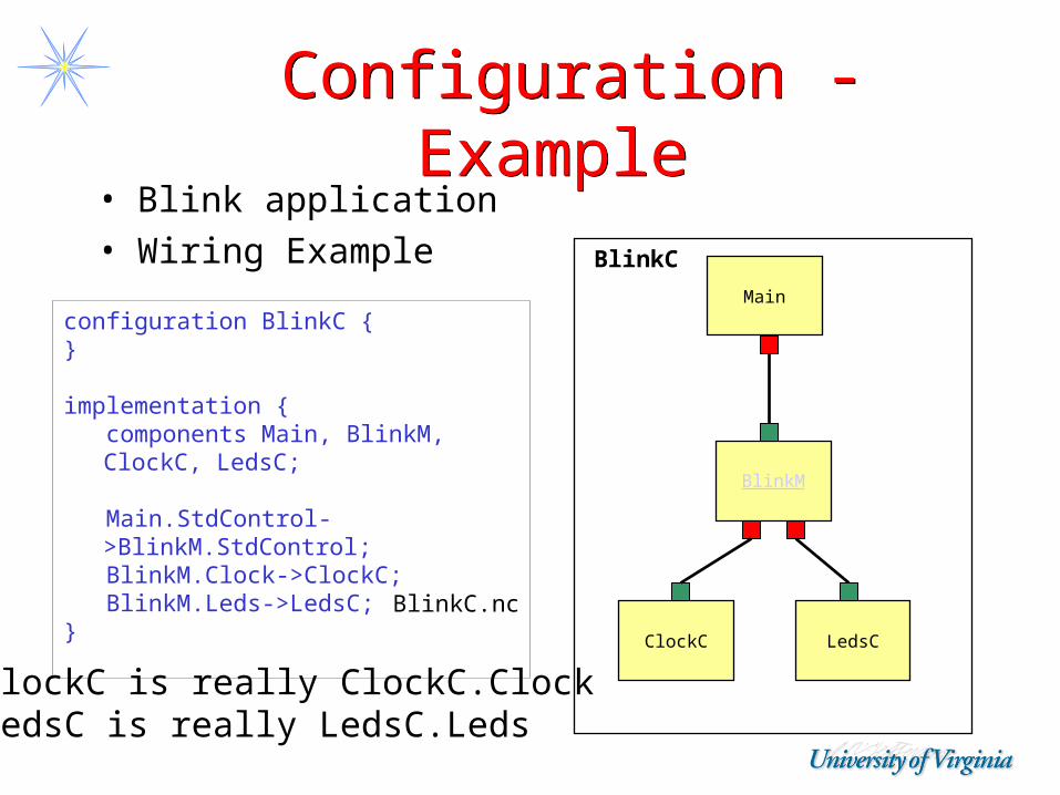
• Blink application• Wiring Example
configuration BlinkC { }
implementation { components Main, BlinkM, ClockC,
LedsC;
Main.StdControl->BlinkM.StdControl; BlinkM.Clock->ClockC; BlinkM.Leds->LedsC;}
ClockC LedsC
Main
BlinkC
BlinkM
BlinkC.nc
ClockC is really ClockC.ClockLedsC is really LedsC.Leds

ConfigurationConfiguration
Main.StdControl -> BlinkM.StdControl
Component Interface Component Interface Implementation
USES PROVIDES

Equals SignEquals Sign
A: provides I
B: provides I
But A does notimplement I butuses what is providedby B
Hence A = B
Often used for hierarchicalConfiguration files – see Example later

ImplementationImplementation
• fn.nc– For all source files (interfaces, modules
and configurations)
Concurrency ModelConcurrency Model
• Underlying execution model (TinyOS)– Tasks and Events– Split phase operation

Tasks Tasks
• Tasks– Deferred computation– Non-preemptable by other tasks– Scheduled FCFS from task queue– When no tasks – CPU goes to sleep– Returns void
– Declare tasks with task keyword– Schedule tasks with post keyword
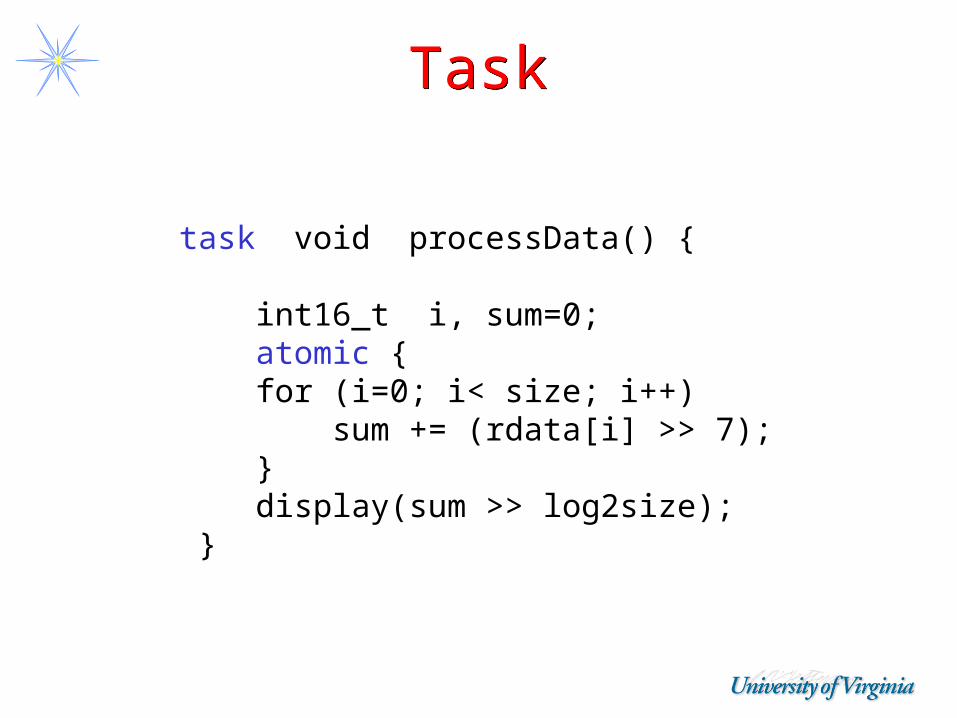
TaskTask
task void processData() {
int16_t i, sum=0; atomic { for (i=0; i< size; i++) sum += (rdata[i] >> 7); } display(sum >> log2size); }
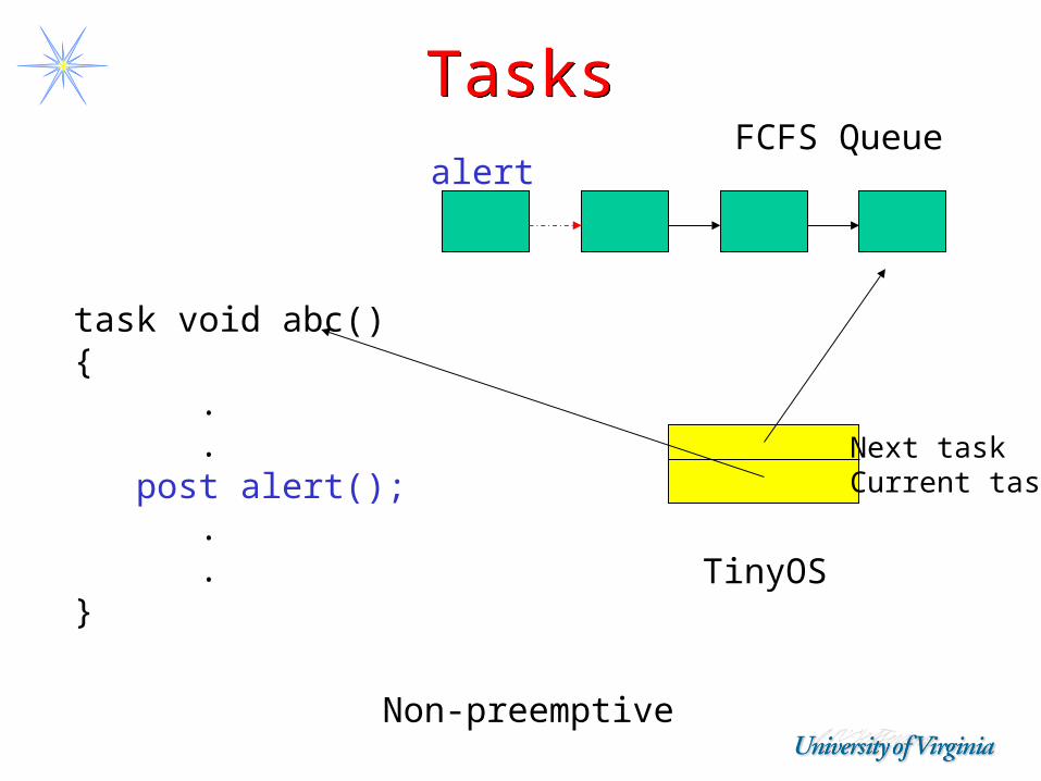
TasksTasks
task void abc(){ . . post alert(); . .}
alert
Next taskCurrent task
TinyOS
FCFS Queue
Non-preemptive

EventsEvents
• Events– Execution of an interrupt handler– Runs to completion– Can preempt tasks and can be
preempted by other events
– Declare events with event keyword (as part of interfaces)
– Notify events with signal keyword

EventsEventsalert
FCFS Queue
Event: BitsSignal Byte
Event: byteHere
Signal packet
Event: packethere
HW interrupt/radio
Asynchronous
PREEMPT
Upcalls
Can postTasks/keepHandlers short

Commands and EventsCommands and Events
• For those commands and events that can be executed by interrupt handlers – explicitly mark as async
async event result_t ADC.ready (uint16_t data) { putdata(data); post processData(); return SUCCESS; }

EventsEvents
• Signify completion of a split-phase operation– Example: packet send via send
command; then communication component will signal sendDone event when transmission is complete
• Events from environment– Message reception– Clock firing

Race ConditionsRace Conditions
• Solutions– Access shared data exclusively within
tasks– Have all accesses within atomic
statementsNon-preemptiveTask queue
Shared data
Event Handlers
x
X

Directions of CallsDirections of Calls
Component
Event Call – use keyword signal
Command Call – use keywordcall

Big PictureBig PictureMain …Task … post tasks call commands signal events …Task … Components (modules) async command … command … async event …
Components (modules) async command post task call commands signal events … command …
HW InterruptsInvoke commandsand events

Components - nesCComponents - nesC
• The nesC model:– Interfaces:
• uses• provides
– Components:• modules• configurations
• Application:= graph of components
Component A
Component B
ComponentD
Component C
Application
configurationconfigurationComponent
E
ComponentF
X = YConfig notation

ModulesModules
• Call commands and Signal events
module TimerM { provides interface StdControl; provides interface Timer[uint8_t id]; uses interface Clock;…}
implementation { command result_t StdControl.stop() { call Clock.setRate(TOS_I1PS, TOS_S1PS); … signal xyz.fired(); } …}
TimerM.nc

ModulesModules• Task: a task is an independent locus of control
defined by a function of storage class task returning void and with no arguments
• Posting tasks: keyword post
module BlinkM {…}implementation {… task void processing () { if(state) call Leds.redOn(); else call Leds.redOff(); }
event result_t Timer.fired () { state = !state; post processing(); return SUCCESS; }…}
BlinkM.nc

Atomic StatementsAtomic Statements
bool busy; // gobal .…bool available;
….
atomic {
available = !busy;busy = TRUE;
} ….
atomic busy = false;
nesC forbids callingcommands or signaling events in anatomic section

Interrupt HandlingInterrupt Handling
• Keep interrupt handlers short• May post tasks• Examples
– Increment counter in atomic statement and then done
– Call LED to set light red; done– Post task; done– Call -> Call -> Call -> Call then return,
…; bad idea

Matching SW and HWMatching SW and HW
• Thin veneer of code for HW devices– See next slide
• Assign symbolic names for signals/pins– Photo_PWR (to turn on power to photo
sensor)
• Abstract away interrupt vectorsHW definedInterruptVectors
InterruptHandler

Matching SW and HWMatching SW and HW
• Example LED– Red LED on/off– Green LED on/off– Yellow LED on/off– Toggle– Turn on/off power
– LED has no interrupts
– User has it easy; just know interface
Components of Interest
Components of Interest
• LED, Clock, UART, ADC, RFM, I2C (hardware abstraction components)
• Other components: Chirp, counter, blink, AM_Beacon, AM_Echo, …
• Find interfaces in– tos/interfaces/

Application Example (revisited)
Application Example (revisited)
RFM
Radio byte
i2c
Tempphoto
Messaging Layer
clocksbit
byte
packet Radio Packet
Routing Layer
sensing applicationapplication
HW
SW
ADC
messaging
routing
UART Packet
UART byte

ADCADC
• init()• get-data()
• Fires separate event for each data port

Programming EnvironmentProgramming Environment
• cygwin/Win2000 or gcc/Linux• Wireless download of code also available
mote
programming board
mote-PC comms
Code download

Summary/Principles/Concepts
Summary/Principles/Concepts
• Single application• Wrap HW devices
in thin veneer of SW– Hide details
• Components + Glue
• Use only components required– Even for OS
• Interfaces• Bi-directional
interfaces
• Tasks and Events– Concurrency
• Split-phase– Asynchronous
• Embedded systems language
• No dynamic memory
• Race conditions– Atomic sections
• Pre-compiler for C

Message CenterMessage Center
• Tool for sending and receiving packets into actual system
• Use tool via 2 windows
• Learn via Lab 2

TOSSIMTOSSIM
• TinyOS Simulator (not typical)– Versus ns2 or glomosim or …
• Write your actual code
• Compile it into TOSSIM framework
• Once debugged – code moved to real platform

TOSSIM FeaturesTOSSIM Features
A discrete event simulator; runs on a PC
High fidelity simulations – capture TinyOS behavior at a low level
Uses TinyOS’ component based architecture

TOSSIM capabilities TOSSIM capabilities Simulates large scale sensor networks
(e.g., thousands)Simulates network at bit level (bit error
per link)Simulates repeatable loss rateSimulates asymmetric linksSimulates each individual ADC captureSimulates every interrupt in the systemTime is kept at 4MHz granularity => 4
million ticks per second

TOSSIM non-capabilities TOSSIM non-capabilities
Does not simulate single strengthDoes not model execution time
No spin locks or task spin locks A piece of code runs instantaneously
Does not model power draw Interrupts are non-preemptiveSimulates the 40Kbit RFM mica
networking stackDoes not simulate the Mica2 ChipCon
CC1000 stack

TOSSIM Radio ModelsTOSSIM Radio Models
Simple: every mote in one cell, bits perfectly transmitted
Lossy: connectivity determined at startup Radio propagation is not modeled, rather an
abstraction of it is (bit error rate) Specified in a file *.nss (use –rf=<file>
option) Specified connectivity Specified bit error rate For example
<mote ID>:<mote ID>:bit error rate 0:1:0.009

Radio ModelRadio Model
0:1:0.0011:0:0.0020:2:0.0012:0:0.9
0 1
2
.001
.002
.001.9 x
Model an asymmetriclink
my_radio_model.nss

Using TOSSIMUsing TOSSIMCompiling TOSSIM
cd apps/Blinkmake pcmake –rf=fname pc
Use: ./build/pc/main.exe [options] <num_nodes>
[options] are (see manual for more):
-k <kb>, -Set radio speed to <kb> Kbits/s. Valid values: 10, 25, 50.-r, specifies a radio model (simple is default)-t, -<sec> tells TOSSIM to run for a specified number of virtual seconds.<num_nodes> number of nodes to simulate

DebuggingDebugging
Your code
…… dbg(DBG_CRC, “crc check failed”); …… dbg(DBG_BOOT, “Sensor initialized”); ……

TOSSIM DebuggingTOSSIM DebuggingKnown dbg flags
(system/include/dbg_modes.h) : all, boot, clock, task, sched, sensor, led, route,
am, crc, packet, encode, radio, logger, adc, i2c, uart, prog, sim, queue, simradio, hardware, simmem (found in TinyOS code)
For use in applications: usr1, usr2, usr3, temp
Insert debug statements in source code dbg(DBG_ROUTE|DBG_ERROR, "Received control
message: lose our network name!.\n");

TOSSIM DebuggingTOSSIM Debugging
Set dbg flags to get the proper debug information When simulator starts it read DBG
environment variable to enable modes For example: export DBG=usr1,route
Only these debug statements will be active!
ImportantImportant
• Once you recompile with mote as target instead of pc (i.e., TOSSIM)
– All debug statements are removed from the executable for you!

Using DebuggingUsing Debugging
• Print to screen or file• Use Serial Forwarder
– Can inject messages to mote 0• -comm tossim-serial
– Can snoop all messages in network• -comm tossim-radio
• Run gdb– gdb build/pc/main.exe
TOSSIMTOSSIM
• See TOSSIM document (read when you are preparing for Lab 3)
• See TOSSIM paper (sections 1-3 inclusive; read now)
• Learn via Lab 3

SummarySummary
• nesC – most widely used today for WSN - systems programming language
• Use naming conventions – see handout
• Lab 0 – mechanics of downloading, etc.• Lab (Programming) Assignments 1-4• Possible Extra Credit Project