programming - satel · fs6 - programming the global times (dec) ... fs101 - programming number of...
TRANSCRIPT

A
larm
Co
ntr
ol P
anel
CA
-6 Firm
war
e V
ersi
on 6
.06
GDAŃSK
ca6fs_en 08/08
PROGRAMMING

Latest EC declaration of conformity and product approval certificates are available for downloading on website www.satel.pl

CONTENTS General ....................................................................................................................................4
Service mode [SERVICE CODE][#] or [SERVICE CODE][*] .............................................4 Programming the control panel service functions from keypad................................................4
BIT functions ........................................................................................................................4 DEC functions ......................................................................................................................4 HEX functions ......................................................................................................................5
Description of the panel service functions................................................................................5 FS0 - quiting service mode ...............................................................................................5
Functions programming basic parameters ...........................................................................5 FS1 - programming service access code..........................................................................5 FS2 - programming control panel password (HEX) ..........................................................6 FS3 - programming computer password (HEX)................................................................6 The factory identifiers can be restored with Function FS109. ...........................................6 FS4 - programming computer telephone number (HEX) ..................................................6 FS5 - programming the system options (BIT) ...................................................................7 FS6 - programming the global times (DEC)......................................................................9 FS7 - programming the counting zone counters (DEC) ....................................................9
Functions programming assignment ..................................................................................10 FS8 - programming A partition zones (BIT) ....................................................................10 FS9 - programming B partition zones (BIT) ....................................................................10 FS16 - programming auto bypassed zones in A partition (BIT) ......................................10 FS17 - programming bypassed zones in B partition (BIT) ..............................................10 FS20 - programming keypad and partition options (BIT) ................................................10
Functions programming zone parameters..........................................................................12 FS24 - programming zone sensitivity..............................................................................12 FS25 - programming zone type (DEC) ...........................................................................12 FS26 - programming zone reaction type (zone function) (DEC) .....................................13 FS27 - programming zone options (BIT).........................................................................14 FS28 - programming individual entry delay (DEC)..........................................................15
Functions programming output parameters........................................................................15 FS31 - programming OUT1 output .................................................................................15 FS32 - programming list of zones for OUT1 (BIT) ..........................................................17 FS33 - programming OUT2 output .................................................................................17 FS34 - programming list of zones for OUT2 (BIT) ..........................................................17 FS35 - programming OUT3 output .................................................................................17 FS36 - programming list of zones for OUT3 (BIT) ..........................................................18 FS37 - programming OUT4 output .................................................................................18 FS38 - programming the list of zones for OUT5 (BIT) ....................................................18 FS39 - programming OUT5 output .................................................................................18 FS40 - programming list of zones for OUT5 (BIT) ..........................................................18
Monitoring - programming parameters of transmission to monitoring stations ...................18 FS43 - programming station 1 telephone number (HEX)................................................18 FS44 - programming station 2 telephone number (HEX)................................................18 FS45 - programming station 1 format (HEX) ..................................................................18 FS46 - programming station 2 format (HEX) ..................................................................18 FS47 - programming monitoring options (BIT)................................................................19
Monitoring - programming identifiers..................................................................................20 FS48 - programming event identifier for station 1 (HEX) ................................................20 FS54 - programming event identifier for station 2 (HEX) ................................................20
Monitoring - programming zone event codes .....................................................................20 FS60 - programming zone alarm codes (HEX)...............................................................20 FS61 - programming zone tamper alarm codes (HEX)...................................................21
FS63 - programming zone violation codes (HEX)...........................................................21 FS64 - programming zone RESTORE (end of violation) codes (HEX) ...........................21 FS65 - programming zone TAMPER RESTORE codes (HEX).......................................21 FS67 - programming zone event assignment to station 1 (BIT)......................................21 FS68 - programming zone event assignment to station 2 (BIT)......................................21
Monitoring - programming partition event codes ................................................................22 FS69 - programming A partition event codes (HEX).......................................................22 FS70 - programming B partition event codes (HEX).......................................................22 FS73 - programming A partition event assignment to station 1 (BIT) .............................22 FS74 - programming B partition event assignment to station 1 (BIT) .............................22 FS77 - programming A partition event assignment to station 2 (BIT) .............................23 FS78 - programming B partition event assignment to station 2 (BIT) .............................23
Monitoring - programming system event codes..................................................................23 FS81 - programming system event codes - set I (HEX)..................................................23 FS82 - programming system event codes - set II (HEX).................................................23 FS83 - programming system event assignment to station 1 (BIT) ..................................24 FS84 - programming system event assignment to station 2 (BIT) ..................................24 FS85 - programming test transmission time (DEC).........................................................25 FS86 - programming the „AC loss” report delay (DEC)...................................................25
Messaging – programming telephone number ...................................................................26 FS87 - programming telephone number 1 (HEX) ...........................................................26 FS88 - programming telephone number 2 (HEX) ...........................................................26 FS89 - programming telephone number 3 (HEX) ...........................................................26 FS90 - programming telephone number 4 (HEX) ...........................................................26 FS95 - programming assignment of partitions and messages (BIT) ...............................26
Messaging – programming of PAGER messages ..............................................................26 FS96 - programming message 1 (POLPAGER format) ..................................................26 FS97 - programming message 2 (POLPAGER) .............................................................26
Messaging – programming of messaging parameters........................................................27 FS100 - programming number of rounds and redial number in a round (DEC) ..............27 FS101 - programming number of rings before answer (DEC).........................................28
Functions programming TIMERS .......................................................................................28 FS102 - programming TIMERA 1 (DEC).........................................................................28 FS103 - programming TIMERA 2 (DEC).........................................................................28 FS104 - programming TIMERA 3 (DEC).........................................................................28 FS105 - programming TIMERA 4 (DEC).........................................................................28 FS106 - programming TIMER functions (DEC)...............................................................28
Special functions ................................................................................................................29 FS107 - restoring default settings ...................................................................................29 FS108 - clearing event log ..............................................................................................29 FS109 - restoring default communication passwords .....................................................29 FS110 - restoring default codes......................................................................................29 FS111 - programming keypad address (BIT)..................................................................29 FS112 - start of programming from computer in local mode...........................................30 FS117 - telephone line trouble delay (DEC) ...................................................................31 FS118 - parameters of pager station signals (HEX) .......................................................31 FS123 - counter count-up times (DEC)...........................................................................32 FS124 - automatic readout of keypad address ...............................................................32 FS125 - programming CTL input functions (HEX) ..........................................................32 FS126 - programming guard control codes (HEX)..........................................................33 FS127 - zones bypassed on no exit from A partition (BIT)..............................................33 FS128 - zones bypassed on no exit from B partition (BIT)..............................................33 FS131 - programming additional options (BIT) ...............................................................33

FS132 - programming clock correction (DEC) ................................................................34 FS133 - reviewing control panel real-time clock (no change possible) ...........................34
Restoring default settings, erasing codes ..............................................................................35 Appendix - CA-6 List of Events ..............................................................................................36 Character Encoding Table for LED Keypads .........................................................................38

General
The CA-6 control panel is characterized by a high flexibility of firmware, which enables their functionality to be customized as per individual requirements of the protected premises. Additionally, some extra functions can be assigned to the panel (for example, control of lighting, locks, cameras). The control panel can be configured from the keypad (locally) or by the computer with a suitable firmware (locally via RS-232 port or remotely via modem). Programming with the keypad is possible after starting the service mode. When programming from the keypad, you should pay attention to information shown by means of the LED indicators and audible signals.
Service mode [SERVICE CODE][#] or [SERVICE CODE][*]
The service mode can be started from the keypad in any disarmed and non-alarming partition. In order to start the service mode, enter the service code (by default=[1][2][3][4][5]) and confirm it with the key [#] or [*]. The service mode is indicated by alternate blinking of the
[POWER] and the [PHONE] LED and a short beep generated every 3 seconds (in the CA-6 KLED-S keypad blinks LED designed ). No keypad tamper contact or address is checked in the service mode. The service mode is on until deactivated by the service function (FS0).
Programming the control panel service functions from keypad
The panel programming is based on three types of functions: bit (BIT), decimal (DEC) and hexadecimal (HEX). The bit functions are used to program two-state parameters: YES and NO (e.g. the functions of zone assignment to partition, options). The decimal functions are used for programming a few digits data (for example, the test transmission time – 4 digits). The hexadecimal functions are used to program hexadecimal data (e.g., monitoring codes). During programming, if the functions have a several options (e.g., FS5, FS27), the number of options set or the number of zone is shown on the [ALARM AB] and [ARMED AB] LEDs.
Calling a separate service function is indicated by lighting of the [TROUBLE] LED.
BIT functions
During programming with a bit function, the LEDs 1 to 8 show the current setting of particular parameters (diode on – YES, off – NO). Pressing the keys [1] to [8] changes the state of the corresponding diode. The state of 8 parameters is confirmed with the [#] key. If the programming function includes more parameters, the control panel will signal with two short beeps acceptance of the first eight parameters and the LEDs 1 to 8 will display the state of the next group of eight. The control panel shows on the [ALARM AB] and [ARMED AB] LEDs the set of options being currently programmed. When all the parameters have been programmed, the control panel will signal exiting the function with four short beeps and a long one. The [*] key makes it possible to quit the function at any time without saving the changes in currently displayed data.
DEC functions
During programming the LEDs 1-4 show the first digit (binary), LEDs 5-8 - the second digit, while the LEDs AB, AB display the counter of digit pairs (binary). The programming consists in entering a two-digit number and confirming it with the [#] key. The control panel will confirm operation with two short beeps. When all the parameters have been programmed, the control

CA-6 SATEL 5
panel will signal exiting the function with four short and one long beeps. The [*] key makes it possible to quit the function at any time without saving the changes in currently displayed data. Make sure that the entered data are correct, because the control panel does not verify the input parameters and programming any wrong settings may result in malfunction of the panel.
HEX functions
During programming the LEDs 1-4 show the first hexadecimal digit, LEDs 5-8 - the second digit, while the LEDs AB, AB display the counter of digit pairs. The programming consists in entering a two hexadecimal digit number and confirming it with the [#] key. If you want to enter the 0-9 digits press the corresponding key, the A-F digits are entered using the combination of keys [*] and [0]...[5] (i.e. A=[*][0], B=[*][1], and so on). Pressing the [*] key results in blinking of the digit, which will be changed after one of the keys [0]...[5] is pressed. The [*][#] combination of keys makes it possible to exit the function without saving changes.
Fig.1. The way of LED indication in keypad
Note: Both in the decimal and hexadecimal function, consecutive pressing of numeric keys result only in displaying the respective number on the LEDs (the state of LEDs 1-4 and 5-8 is alternately changed). Only by pressing the [#] key you will save the status of the parameter displayed on the diodes.
The character encoding table can be found at the end of this Manual.
Description of the panel service functions Next to the some functions in brackets is given an information on entering data: bit (BIT), decimal (DEC) or hexadecimal (HEX). If the function description contains no detailed information on programming, the data are entered in the panel as described in the previous section for the specific type of function.
FS0 - quitting service mode The [0][#] combination of keys ends the service mode. The control panel starts functioning in accordance with the new settings. Exiting the service mode is signaled in all partitions with four short and one long beeps.
Functions programming basic parameters
FS1 - programming service access code The service code enables activation of the service mode. It can be from 4 to 6 digits long.
1. digit
2. digit counter

6 Programming CA-6
EXAMPLE: changing the service code from 12345 to 78901 [12345] [#] - enter the service mode [1] [#] - call the service function 1 [78901] [#] - enter the new code and confirm it; the function will be automatically exited
FS2 - programming control panel password (HEX) FS3 - programming computer password (HEX) In the DOWNLOADING mode (see: Installer Manual), the control panel, having established connection with the computer, sends a six-character panel password and waits for the password (identifier) of the answering computer. When the appropriate identifier is received, the transmission to computer can begin. On receiving an identifier other than that programmed with this function, the control panel will hang up. The control panel will accept no command from the computer, unless the computer identifier is valid. Programming of this identifiers consists in entering three pairs of hexadecimal characters (digits from 0 to 9 and characters A, B, C, D, E, F - see the table of codes), in the following order: [first][second][#], [third][fourth][#], [fifth][sixth][#]. The LEDs at first display previous settings, and, after the change – the values of entered characters (binary, the first character - LEDs 1 to 4, the second – LEDs 5 to 8, number of programmed characters pairs - LEDs AB, AB). Having entered the last pair of characters, the panel automatically exits the function.
EXAMPLE: programming the identifier 23C4D5 [12345] [#] - enter service mode [2] [#] - call the required function [2][3] [#] - enter the two first characters [*2][4] [#] - enter the two next characters [*3][5] [#] - enter the two last characters; after acknowledging them the panel will automatically exit
the function
The factory identifiers can be restored with function FS109.
FS4 - programming computer telephone number (HEX) The computer telephone number is necessary for initiating communication from the control panel keypad (user function “0”). When communication is initiated from the computer, the panel, after the communication passwords exchange, hangs up and calls back the computer. If the computer telephone number is not programmed, it is possible to initialize the communication from the computer in a simplified way - the control panel will not hang up and call back. The telephone number can consist up to sixteen digits and special characters. The special characters are used to control the dialing process. Telephone number is programmed by entering the consecutive digits and characters in pairs. Each pair is to be confirmed by the [#] key (see the example below). The LEDs AB, AB show (binary) which pair of characters is being programmed, and the LEDs 1-4 and 5-8 show (also binary) the values of programmed digits.

CA-6 SATEL 7
Special characters in the telephone number:
Special character Programming Function description Indication (HEX)
A [*][0] special character A
AA [*][0][*][0] end of number AA
B [*][1] pulse dialing B
C [*][2] tone dialing C
D [*][3] waiting for dial tone D
E [*][4] short pause (3 sec.) E
F [*][5] long pause (10 sec.) F
[*][0][0] signal in DTMF mode A0
# [*][0][1] # signal in DTMF mode A1
a [*][0][2] A2
b [*][0][3] A3
c [*][0][4] A4
d [*][0][5]
other signals generated in DTMF mode
A5
EXAMPLE: programming the number 0 - 556 40 31 (0D 55 64 03 1A) [12345] [#] - enter the service mode [4] [#] - call the required function [0][*3] [#] - enter the two first characters [5][5] [#] - enter the two next characters [6][4] [#] - enter the two next characters [0][3] [#] - enter the two next characters [1][*0] [#] - enter the next character and the special character A [*0][*] [#] - enter the second part of the special code AA (end of telephone number), quit function
after entering 11 characters ([*][#])
Notes: • Special signals generated in the DTMF system require that two characters be taken up
in the telephone number (A and corresponding digit).
• Do not program the control characters from B to F before the telephone number (the basic mode of number dialing and the dial tone test prior to the dialing are programmed in FS5).
• End any telephone number being shorter than 16 characters with the special AA code („AA” means end of number).
• Waiting for the dial tone (D code) will not reduce the counter of rounds and redials in case of a busy signal (e.g. when the control panel is connected to the local line and the outside line is busy, the panel keeps on dialing until successful). Only after the whole number has been dialed, the busy signal or no answer signal will change the counters.
If the CA-6 fails to establish connection with the computer, it will hang up after four retries.
FS5 - programming the system options (BIT) The function programs 3 sets of options, which define the control panel operating mode.

8 Programming CA-6
FIRST SET – the lower B diode is blinking
No LED Option
ON voice/pager messaging on (alarm reporting) 1
OFF voice/pager messaging off
ON monitoring on 2
OFF monitoring off
ON tel. answering on 3
OFF tel. answering off
ON in case of problems with transmission to the station, reporting will be suspended until a new event occurs 4
OFF monitoring suspended for 30 min.
ON only 3 successive events of test transmission are stored in memory 5
OFF all events of test transmission are stored in memory
Notes: • The option 5 should be enabled if test transmissions are conducted frequently. Only
3 successive events of the test transmission are then saved in memory. Next transmissions will not be saved, thus preventing the events memory of the control panel from being quickly filled up. Occurrence of any event other than test transmission will reset the blocking and activate event saving, which means that next three test transmissions can be written to memory.
• The options 6 to 8 from the first set of the options are irrelevant.
SECOND SET – the lower A diode is blinking
No LED Option
ON external DOWNLOADING enabled 1
OFF external DOWNLOADING disabled
ON TONE dialing 2
OFF PULSE dialing
ON double voice message from synthesizer 3
OFF single voice message from synthesizer
ON GROUND START signal generated before dialing (special telephone exchanges) 4
OFF GROUND START signal blocked
ON no dial tone test before dialing the number 5
OFF dial tone test activated (dialer waits for a dial tone before dialing the number)
ON No tel. answer test (voice message generated after 15 s from the moment the number is dialed)
6 OFF
call answer test activated (the dialer sends the message after detecting the call answer)
ON OUT4, OUT5 outputs control the radio messaging (NOKTON) 7
OFF OUT5, OUT6 outputs perform assigned functions
ON double call to answer 8
OFF single call to answer

CA-6 SATEL 9
THIRD SET – the lower A and B diodes are blinking
No LED Option
ON downloading unavailable if any partition is armed 2
OFF downloading always available
ON alarm if zones are violated after the exit delay elapses 3
OFF control panel does not alarm if zones in partition are violated after the exit delay elapses
ON OUT4 and OUT5 outputs work in „UA” format 7
OFF OUT4 and OUT5 outputs work in PC16OUT format
Note: The options: 1,4,5,6 and 8 from the third set of options are irrelevant in the CA-6.
FS6 - programming the global times (DEC) The settings refer to the entry delay, exit delay and alarm time. The times are valid for the entries and exits to which no individual times are assigned. The exit delay time is common for all partitions. In case of the entry delay time it is possible to program an individual delay for each zone and In case of the alarm time it is possible to program a separate time for each output. The alarm time programmed in this function refers also to the keypad alarm signaling.
Note: The alarm time set with the function FS6 defines also the zone alarms blocking time - when the alarm is on, the subsequent zone violations will not trigger consecutive alarms until the blocking time elapsed.
Programming the times is carried out in the following order: - entry delay (from 00 to 99 seconds ) - the lower B diode is blinking, - exit delay (from 00 to 99 seconds) - the lower A diode is blinking, - alarm time (from 00 to 99 seconds) - the A and B diodes are blinking.
EXAMPLE: programming the times: entry delay=30s, exit delay=60s, alarm=90s [12345] [#] - enter the service mode [6] [#] - call the required function [3][0] [#] - enter the entry delay time (two digits) – the lower B LED is blinking [6][0] [#] - enter the exit delay time (two digits) – the lower A LED is blinking [9][0] [#] - enter the alarm time – the A and B LEDs are blinking - after acknowledging the last
settings, the control panel automatically exits the function
FS7 - programming the counting zone counters (DEC) The control panel is equipped with three independent violation counters which can be associated with any zones. Violation of these zones triggers an alarm after the programmed number of violations is exceeded. All the violations must occur within a specific period of time. Each counter can sum up violations of one or several zones defined as the counting zones (e.g. the counter 1 can count violations of zone 2, the counter 2 - violations of zones 4, 5, 6). The alarm will be generated by the zone which has been violated as the last one. Three counter values are programmed, from 01 to 07, in the following order: counter 1, counter 2, counter 3. If no counting zones are provided in the panel, the programmed values are irrelevant. If "00" has been programmed, the counting zone will operate as the instant one. Count times of the counters are programmed in FS123.

10 Programming CA-6
EXAMPLE: programming the counters: the 1st - 2 violations, the 2nd - 5 violations, the 3rd - without
changes [12345] [#] - enter the service mode [7] [#] - call the required function [0][2] [#] - program the first counter (the lower B LED is blinking) [0][5] [#] - program the second counter (the lower LED A is blinking) [*] - exit the function - programming of the third counter is omitted In case of programming three counters, the function is automatically exited after the third
counter
Functions programming assignment
FS8 - programming A partition zones (BIT) FS9 - programming B partition zones (BIT) The functions FS8 and FS9 are used to divide the alarm system into partitions. It is possible to assign any zone to the partitions. Independent sirens and messaging telephone numbers can be assigned to the partitions, and separate access codes can be programmed – thus creating two independent alarm systems. Optionally, the so-called interior partition can also be created (if one partition is to be fully contained in the other). When both partitions are armed, it is possible to disarm the interior partition by using its code. The other zones, which belong to the primary partition, will remain armed.
Note: If the armed mode is activated by means of the primary partition code, the interior partition zones will be automatically armed as well, but their status as a partition status will not be signaled by the control panel – the [ARMED] LED, which corresponds to the interior partition, is "off".
A zone can be assigned to both partitions at the same time. The common zone will only be armed, when both partitions are armed (if the partitions do not contain one another, i.e. the partition is not the interior one). Zones can be assigned to the partition by pressing the keys 1 to 8, which is shown by lighting of the LED which indicates the respective zone. Use the [#] key to confirm the selection and exit the function. Use the [*] key to interrupt the programming.
FS16 - programming auto bypassed zones in A partition (BIT) The AUTO BYPASS function applies to the zones which are automatically bypassed after arming with the 7 authority level code (partial arming), assigned to the A partition. The same zones are bypassed after silent arming of the A partition. The control panel permits also programming another set of automatically bypassed zones: bypassed when no exit from the partition (EXIT-BYPASS zones - with service functions FS127, FS128). The programming is similar to the programming of FS8 function. After the corresponding diodes are turned on the [#] key should be pressed.
FS17 - programming bypassed zones in B partition (BIT) The function refers to the automatically bypassed zones in B partition. The programming as in FS16.
FS20 - programming keypad and partition options (BIT) Some of the user functions and the keypad beeps are optional. The FS20 function defines which of them are to be performed. Two sets of options are programmed, each of them need to be confirmed with the [#] key.

CA-6 SATEL 11
FIRST SET - the lower B diode is blinking
No LED Option
ON quick arming, A partition [1][#] disabled 1
OFF quick arming, A partition [1][#] enabled
ON quick arming, B partition [2][#] disabled 2
OFF quick arming, B partition [2][#] enabled
ON quick arming, A and B partition [0][#] disabled 3
OFF quick arming, A and B partition [0][#] enabled
ON 3 incorrect codes alarm disabled 5
OFF 3 incorrect codes alarm enabled
ON PANIC alarm from keypad disabled 6
OFF PANIC alarm from keypad enabled
ON AUX alarm from keypad disabled 7
OFF AUX alarm from keypad enabled
ON FIRE alarm from keypad disabled 8
OFF FIRE alarm from keypad enabled
Note: Option no. 4 of the first set is not used.
SECOND SET - the lower A diode is blinking
No LED Option
1 ON keypad alarm until cleared (if LED 2 is off)
2 ON alarm in keypad during the global alarm time
1 & 2 OFF no keypad alarm
ON DAY/NIGHT or COUNTING zone violation signaled in keypad (5 long beeps) 3
OFF no DAY/NIGHT or COUNTING zone violation signaled in keypad
ON CHIME signalling on (five short beeps) 4
OFF CHIME signalling off
ON trouble signalling on (two short beeps) 5
OFF trouble signalling in keypad off
ON EXIT DELAY signalling on (one long beep every three seconds) 6
OFF EXIT DELAY signalling off
ON ENTRY DELAY signalling on (one sort beep every three seconds) 7
OFF ENTRY DELAY signalling off
ON key press sounds 8
OFF no key press sounds

12 Programming CA-6
Functions programming zone parameters
FS24 - programming zone sensitivity Each zone of the CA-6 can have an individual reaction time. Violations lasting shorter than the programmed reaction time are disregarded by the control panel. Programming the zones sensitivity in keypad is performed in a different way, than programming the other parameters. The programming includes values from 1 to 255 which corresponds to the times from 16 ms to 4080 ms according to the formula: REACTION TIME = PROGRAMMED VALUE x 16 ms By default, all the zones have the same reaction time (480 ms). In most cases, no change of the time setting is required. The function is intended for advanced installers. It allows the zone sensitivity to be selected when special detectors are used (for example, mechanical glass break detectors, or low hysteresis detectors, not fitted with monovibrator at the output).
Note: The minimum keypad zones sensitivity is 64ms (4 x 16 ms). The actual sensitivity values of these zones can amount to n x 64ms (n=1,2,3,...). This results from the way the keypad is operated by the control panel – the zones status is read out at 64ms intervals.
During programming, the AB, AB LEDs indicate which zone the parameter refers to. The zone number is displayed in binary format (for zone no. 1 – the lower B LED is blinking, for zone no. 2 – the lower A LED, for zone no. 3 – both of them, etc.). After setting a value for the given zone, press the [#] key to proceed to programming the reaction time of the next zone. After the last parameter is entered and confirmed, the control panel exits the function. The introduced changes will only be displayed after the function is reentered. The programming can be interrupted by using the [*] key. EXAMPLE: changing the reaction time of zones 1, 3 and 6 to 800 ms, zone 8 to 100 ms, the other
zones unchanged 800 ms/16 ms = 50 (enter this value for zones 1,3 and 6) 100 ms /16 ms = 6.25 (enter 6 for zone 8, it will ensure the reaction time = 96 ms) [12345] [#] - enter the service mode [2][4] [#] - call the function [5][0] [#] - reaction time for the first zone (AB, AB LEDs = 0001) [#] - confirm the second zone time (AB, AB LEDs = 0010) [5][0] [#] - reaction time for the third zone (AB, AB LEDs = 0011) [#] - confirm the fourth zone time (AB, AB LEDs = 0100) [#] - confirm the fifth zone time (AB, AB LEDs = 0101) [5][0] [#] - reaction time for the sixth zone (AB, AB LEDs = 0110) [#] - confirm the seventh zone time (AB, AB LEDs = 0111) [6] [#] - reaction time for the eighth zone (AB, AB LEDs = 1000) the control panel automatically exits the function
Note: The parameter is entered in decimal and indicated in binary format.
A new value can be checked only after reentering function. It is displayed in binary format on LEDs from 1 to 8. The LEDs which are off mean 0. The value of the LEDs which are on corresponds with the table below:
LED number 1 2 3 4 5 6 7 8
Bit weight 128 64 32 16 8 4 2 1

CA-6 SATEL 13
EXAMPLE: LEDs: 1,3,6,8 are on, which gives value = 165:
State of the LEDs from 1 to 8 :
VALUE : 128+32 + 4+1 = 165
REACTION TIME (ms): PROGRAMMED VALUE (165) X 16 ms = 2640 ms
FS25 - programming zone type (DEC) Selection of the zone type depends on the detector type and configuration of connection to the control panel. The following types of detectors and configurations are possible: NC, NO, EOL, 2EOL/NC, 2EOL/NO. Determination of the configuration and the detector type is necessary, since control panel interpretation of received information will depend on it. For example, an open zone can mean correct state of the NO detector or violation of the NC detector, as well as tamper in case of 2EOL configuration. Programming consists in entering the suitable two-digit number (to determine the zone type) for the particular zones. Having confirmed the detector type for one zone, the control panel proceeds to programming the next zone type, until zone types are assigned to all 16 zones. The following numbers are correct: 00 - no detector (for unused zones) 01 - NC (normally closed) 02 - NO (normally open) 03 - EOL (end of line resistor –by default) 04 - 2EOL/NC (double end of line resistor – NC type detector) 05 - 2EOL/NO (double end of line resistor – NO type detector) During the programming, the control panel displays the current parameter setting (in binary format) on LEDs 1 to 8. The AB, AB LEDs show the zone for which the detector type is being programmed.
EXAMPLE: programming the EOL zones type for 1 - 6 zones, NC type for 7 - 8 zones, [12345] [#] - enter the service mode [2][5] [#] - call the function [0][3] [#] - detector type for the first zone (AB, AB = 0001) [0][3] [#] - detector type for the second zone (AB, AB = 0010) [0][3] [#] - detector type for the third zone (AB, AB = 0011) [0][3] [#] - detector type for the fourth zone (AB, AB = 0100) [0][3] [#] - detector type for the fifth zone (AB, AB = 0101) [0][3] [#] - detector type for the sixth zone (AB, AB = 0110) [0][1] [#] - detector type for the seventh zone (AB, AB = 0111) [0][1] [#] - detector type for the eighth zone (AB, AB = 1000) the control panel automatically exits the function
FS26 - programming zone reaction type (zone function) (DEC) The control panel reaction to a zone violation depends on the function assigned to the given zone (e.g., the reaction will be different in case of a “24 h fire” type zone violation, and in case of an “arming” zone violation). The programming consists in entering an appropriate two-digit number for each zone to determine its function (reaction type). Each of the CA-6 zones can perform one of the 20 functions: 00 - ENTRY/EXIT 01 - DELAYED 02 - INTERIOR DELAYED 03 - INSTANT 04 - DAY/NIGHT 05 - COUNTING C1

14 Programming CA-6
06 - COUNTING C 2 07 - COUNTING C 3 08 - 24H AUDIBLE 09 - 24H AUXILIARY 10 - 24H SILENT 11 - 24H FIRE 12 - ARMING 13 - SILENT ARMING 14 - DISARMING 15 - NO ALARM ACTION 16 - ARM/DISARM 17 - DELAYED WITH SIGNALLING 18 - ARMING WITH BYPASS 19 - PERIMETER
FS27 - programming zone options (BIT) Each control panel zone has eight options which activate additional functions of the zone. The use of these options depends on the zone type. The control panel performance only these function, which are relevant to the given zone. For example, it is no use to activate the "auto-reset 1” (bypassed after first alarm) option or the "priority" option (arming impossible, if the zone with activated option is violated) for the "arming" type zones. Activation of such options has no effect. Activation of the options is carried out individually for each zone and consists in lighting up the corresponding LEDs. The LEDs 1 to 8 have been assigned the following options:
No LED Option
ON PRIORITY (arming impossible, if the zone with activated option is violated or tampered) 1
OFF arming possible, even if the zone with activated option is violated or tampered
ON CHIME (zone generates chime signal when disarmed) 2
OFF zone does not generate chime signal
ON zone bypassed after first alarm (AUTO-RESET 1) 3
OFF always alarms (when both options 3 and 4 are off)
ON zone bypassed after third alarm (AUTO-RESET 3) 4
OFF always alarms (when both options 3 and 4 are off)
ON information on the zone violation will not be reported to the monitoring stations if the violation occurred during the entry delay (ABORT DELAY) 5
OFF information on the zone violation during the entry delay will be reported
ON zone will be bypassed for 120 sec. after power is switched on (which prevents triggering alarms e.g. when starting the control panel) (POWER UP DELAY) 6
OFF zone controlled immediately after power-up
ON zone violation end code will be reported to the monitoring station not immediately but only after alarming is over (RESTORE AFTER BELL)
7
OFF zone violation end code will be reported to the monitoring station immediately (if option 8 is off)

CA-6 SATEL 15
ON zone violation end code will be reported to the monitoring station not immediately but only after the zone is disarmed (RESTORE AFTER DISARM)
8 OFF
zone violation end code will be reported to the monitoring station immediately (if option 7 is off)
During programming, the AB, AB LEDs show the zone number for which the options are being programmed.
Note: By default, the option no. 1 is active for all of the zones, which means that arming is impossible, if any of the zones is violated or tampered.
FS28 - programming individual entry delay (DEC) Where different entry delay times are required for the particular zones, it is possible to program individual "entry delay time" (alarm delay). The programming consists in entering the time for delayed zones from 00 (then the global time specified in FS6 is valid) to 99 seconds. The programmed times refer only to the ENTRY/EXIT, DELAYED, INTERIOR DELAYED and 24h AUDIBLE zone types. If the entry delay is programmed for other zones than the delayed ones (e.g., for the INSTANT zones), it will have no effect on the reaction type of those zones.
EXAMPLE: programming the entry delay time (alarm delay) for the following zones: zone 4 - delay
30s, zone 7 - delay 45s, zone 8 - delay 60s. 12345] [#] - enter the service mode [2][8] [#] - call the function [#] - skip programming entry delay for zone 1 [#] - skip programming entry delay for zone 2 [#] - skip programming entry delay for zone 3 [3][0] [#] - program the entry delay for zone 4 [#] - skip programming entry delay for zone 5 [#] - skip programming entry delay for zone 6 [4][5] [#] - program the entry delay for zone 7 [6][0] [#] - program the entry delay for zone 8 [*] - exit the function
Functions programming output parameters
FS31 - programming OUT1 output The function makes it possible to define three parameters regarding the OUT1 output: After selecting the function, the LEDs 1 to 8 show the respective parameter setting, while the LEDs A,B show which parameter is being programmed.
• Output function (B diode is blinking) - the programming consists in entering a two-digit number (identically as in the DEC functions) and confirming it with the [#] key, which is followed by an automatic jump to next parameter programming. It is possible to program one of the functions below for each zone, and thus specifying situations when the output will be activated: 00 - NOT USED 01 - BURGLARY 02 - FIRE/BURGLARY 03 - FIRE 04 - KEYPAD ALARM 05 - FIRE FROM KEYPAD 06 - PANIC FROM KEYPAD 07 - MEDICAL (AUX) FROM KEYPAD 08 - TAMPERING (KEYPAD/MODULE)

16 Programming CA-6
09 - DAY ALARM 10 - DURESS ALARM 11 - CHIME 12 - MONO SWITCH 13 - BI SWITCH (ON/OFF) 14 - ARMED STATUS 15 - SILENT ARMING STATUS 16 - EXIT DELAY STATUS 17 - ENTRY DELAY STATUS 18 - TELEPHONE LINE IN USE STATUS 19 - GROUND START 20 - MONITORING ACKNOLEGMENT 21 - BYPASS STATUS 22 - READY STATUS 23 - ZONE VIOLATION 24 - TELEPHONE LINE TROUBLE STATUS 25 - AC POWER LOSS 26 - BATTERY TROUBLE 27 - POWER SUPPLY 28 - FIRE DETECTORS POWER SUPPLY 29 - RESETABLE POWER SUPPLY 30 - TIMER 31 - AUDIBLE ARMING STATUS 32 - FULL ARMED STATUS 33 - ARM/DISARM 34 - ALARM IN KEYPAD 35 - POWER SUPPLY ON ARMED 36 - SIGNALLING: LED 37 - SIGNALLING: RELAY 38 - not used – do not program 39 - NO GAURD ROUND 40 - SERVICE MODE STATUS 41 - BATTERY LOW STATUS
• Output operation time (A diode is blinking) - option is programmed from 00 to 99 (DEC). Entered numbers should be confirmed with [#] key. A corresponding option (see below) defines whether the operation time has been given in seconds or minutes.
• Output options (A and B diode is blinking) - programming the set of eight options consists in defining i.a. the output assignment to partitions, and other details of the output operation. The options are programmed in much the same way as the other BIT functions. After the option is accepted with the [#] key, the function is exited.
No. LED Option
ON output belongs to A partition 1
OFF output not assigned to A partition
ON output belongs to B partition 2
OFF output not assigned to B partition
ON pulse signal 5
OFF steady signal

CA-6 SATEL 17
ON operation time in minutes 6
OFF operation time in seconds
ON LATCH type output – signaling until cleared (operation time irrelevant) 7
OFF programmable output operation time
ON polarity +12V when the output is active 8
OFF polarity 0V when the output is active
Note: The option of output assignment to the partition is to be used, when separate sirens have to be assigned to individual partitions. If not assigned to a partition, the alarm output will signal every alarm.
EXAMPLE: programming the OUT1 output as the BURGLARY/FIRE ALARM type with 5 minutes
operation time and polarity 0V in active state [12345] [#] - enter the service mode [3][1] [#] - call the function. The LEDs 1-8 shows number of current output type (LEDs 1-4 shows
binary first digit, LEDs 5-8 – second digit). The blinking B LED signals the output type being programmed
[0][2] [#] - enter and confirm the number of output function (the A LED starts blinking - operation time programming)
[0][5] [#] - program and confirm the time (A and B LEDs start blinking - output option programming) [6] - LED 6 goes on - the „time in minutes” option is activated
[8] [#] - LED 8 goes off - set the "polarity" = 0V and exit the function
Note: Choosing a partition in the options will determine which access code is to be used to switch off siren or to control a zone. The same effect is provided by defining a list of zones controlling the outputs.
FS32 - programming list of zones for OUT1 (BIT) The function is used to program the output controlling zones. The selection of zones limits the output operation only to the reaction to violation of those particular zones. The zone selection should only be used when it is necessary to have separate signaling for events from a specific zone or a group of zones. If no list of zones is programmed, the control panel will assume by default that the output reacts to events from any zone – for example, the BURGLARY alarm type output will signal alarms for each control panel alarm zone. Of course, the zone function (reaction type) is taken into consideration, e.g. the alarm signaling output does not react if the state of the arming zone changes. If the list of zones has been programmed the control panel will skip the programmed selection of partitions. The FS32 function is used to assign zones to the OUT1 output. The programming consists in lighting up the LEDs which correspond to the zones. When the list is completed, it should be confirmed.
FS33 - programming OUT2 output The function allows for defining the basic parameters associated with the OUT2 output. The programming procedure is the same as for the FS31.
FS34 - programming list of zones for OUT2 (BIT) The function programs the list of zones associated with the OUT2 output. The programming procedure is the same as for the FS32.
FS35 - programming OUT3 output The function defines the basic parameters associated with the OUT3 output. The programming procedure is the same as for the FS31.

18 Programming CA-6
FS36 - programming list of zones for OUT3 (BIT) The function programs the list of zones associated with the OUT3 output. The programming procedure is the same as for the FS32.
FS37 - programming OUT4 output The function defines the basic parameters associated with the OUT4 output. The programming procedure is the same as for the FS31.
FS38 - programming the list of zones for OUT5 (BIT) The function programs the list of zones associated with the OUT5 output. The programming procedure is same as for the FS32.
FS39 - programming OUT5 output The function defines the basic parameters associated with the OUT5 output. The programming procedure is the same as for the FS31. FS40 - programming list of zones for OUT5 (BIT) The function programs the list of zones associated with the OUT5 output. The programming procedure is same as for the FS32.
Monitoring - programming parameters of transmission to stations
FS43 - programming station 1 telephone number (HEX) FS44 - programming station 2 telephone number (HEX) In functions FS43 – FS44 are programmed numbers of up to 16 characters (digits and control codes) in the same way as the computer telephone number (FS4).
FS45 - programming station 1 format (HEX) FS46 - programming station 2 format (HEX) The functions FS45 – FS46 define the standard of event transmission to the monitoring stations. The programming consists in entering a double-character number of format according to the list below and confirming it with the key [#]. TRANSMISSION FORMATS:
00 - Silent Knight, Ademco slow (1400Hz, 10Bps) 01 - Sescoa, Franklin, DCI, Vertex (2300Hz, 20Bps) 02 - Silent Knight fast (1400Hz, 20Bps) 03 - Radionics 1400Hz 04 - Radionics 2300Hz 05 - Radionics with parity 1400Hz 06 - Radionics with parity 2300Hz 07 - Ademco Express (DTMF) 08 - Silent Knight, Ademco slow, extended 09 - Sescoa, Franklin, DCI, Vertex, extended 0A - Silent Knight fast, extended 0B - Radionics 1400Hz, extended 0C - Radionics 2300Hz, extended 0D - do not program 0E - Contact ID selected codes 0F - Contact ID full
Notes: • In the Contact ID (CID) format not all events have a CID code assigned to them (see:
Appendix – control panel events list). Monitored are all events with the CID code.

CA-6 SATEL 19
• In the 0E format (Contact ID selected codes) monitored are all events which have a CID code and which are assigned, respectively, to the station 1 or 2 in the corresponding event assignment functions of the control panel, while the events which have no assignment function (marked in the „Appendix” table as no assignment) are only monitored when any non-zero monitoring code has been programmed for them.
• The telephone line restore and trouble events are always monitored in both Contact ID formats, while they are not monitored in the other formats.
FS47 - programming monitoring options (BIT) These options determine the way communication is established with the monitoring stations and how the event codes are transmitted. The programming consists in lighting up the LEDs of selected options and confirming the choice with the [#] key.
No. LED Option 1 OFF 2 OFF
transmission to station 1 or station 2 (report is sent to the one station only, to that, which first answers the call, without event sorting)
1 ON 2 OFF report to station 1 only, without event sorting
1 OFF 2 ON report to station 2 only, without event sorting
1 & 2
1 ON 2 ON
transmission to both stations with event sorting (event sorting programmed with corresponding service functions, separately for each group of events)
ON reported partition event code extended with user number (access code number) 5
OFF automatic extension with user number disabled
ON reported zone event code extended with zone number (for zone 1 - "1", for zone 2 - "2" and so on) 6
OFF extension with the zone number disabled
ON panel does not send the event code if STATION 1 fails to acknowledge receiving the information after 16 attempts 7
OFF the panel skips no codes for STATION 1
ON the panel skips sending the events code if STATION 2 fails to acknowledge receiving the information after 16 attempts 8
OFF the panel skips no codes for STATION 2
Notes: • In case of data formats 4/1 and 3/1, do not enable the options 5 and 6.
• The options 5 and 6 are only meaningful when double-character codes are reported. If this is the case, single-character event codes are programmed (the second character being 0), and the panel, with the extension option on, will add the zone number or the user number, respectively, as the second character. The codes programmed as double-character (both characters different from 0) will be sent in their programmed form, with no extension. Extension of the event codes by adding the zone / user number makes it possible to enter identical codes for one type of events for all zones or partitions, and then to differentiate between them, based on the added zone / user no. (e.g., it is sufficient to program just one, identical character for all zones from which the zone alarm code (FS60) is to be sent). This solution has been adopted to facilitate programming of the event codes.
• The options 3 and 4 are not used.

20 Programming CA-6
Monitoring - programming identifiers
FS48 - programming event identifier for station 1 (HEX) FS54 - programming event identifier for station 2 (HEX) The functions FS48 (station 1) and FS54 (station 2) are used to program the identifiers transmitted to the monitoring stations. Programming is carried out in the manner typical for hexadecimal functions (HEX); the LEDs 1 to 8 shows two consecutive characters, which can be changed by entering new ones. When the first two characters are being programmed, the lower B LED blinks, and when the other two - the lower A LED. For the data formats 3/1 and 3/2, the last character should be 0 - the control panel will send characters from 1 to F, 0 not being sent.
Note: If the monitoring station requires an identifier containing the digit zero, enter the character “A” instead of zero (e.g. the identifier “1203” should be entered as “12A3”).
EXAMPLE: programming the identifier for the station 1 = A243 [12345] [#] - enter the service mode [4][8] [#] - call the function [*0][2] [#] - enter the first two characters of identifier (B LED blinking) [4][3] [#] - enter the next two characters of identifier (A LED blinking) and confirm them - exit the
function
Monitoring - programming zone event codes
The zone event codes are programmed in the functions FS60, FS61 and from FS63 to FS65. Each of them is used for programming a code of one event for each of the eight zones. The zone event codes may be either single or double character. If a single-character code is entered (for the data formats 4/1 and 3/1 and also when using the mode with code extension by zone number, see FS47 "Monitoring options"), one of the characters must be 0. Programming 00 will result in skipping the event when the events are being reported to the station. The programming consists in entering two characters (from 0 to F) for each zone and confirming them. During the programming, the keypad LEDs show value of the character entered (from 1 to 4 - the first character, and from 5 to 8 - the second character of the code) and number of the zone for which the code is programmed (AB, AB LEDs). After the last zone code is confirmed, the control panel exits the function .
FS60 - programming zone alarm codes (HEX) The codes programmed with this function are reported when the control panel detects zone violation, which triggers an alarm. Codes of 8 control panel zones are programmed in turn.
EXAMPLE: programming the alarm codes for the zones 1 to 7 (codes from 41 to 47), the zone 8 is
not an alarm one. [12345] [#] - enter the service mode [6][0] [#] - call the function [4][1] [#] - program the code for zone 1 [4][2] [#] - program the code for zone 2 [4][3] [#] - program the code for zone 3 [4][4] [#] - program the code for zone 4 [4][5] [#] - program the code for zone 5 [4][6] [#] - program the code for zone 6 [4][7] [#] - program the code for zone 7 [0][0] [#] - program the code for zone 8 (no event for zone 8), exit the function

CA-6 SATEL 21
FS61 - programming zone tamper alarm codes (HEX) The codes programmed with this function are reported when the CA-6 detects violation of the tamper contact in 2EOL/NC and 2EOL/NO line, which triggers a tamper alarm.
FS63 - programming zone violation codes (HEX) The function is used for programming the zone violation codes. The zone violation code is transmitted to the monitoring station in case of: • violation of an armed delayed zone (of entry/exit, interior delayed, delayed type)
when the control panel has started the entry delay countdown, • violation of an armed counting zone when the number of violations still does not
trigger an alarm, • violation of a day/night zone when it is disarmed, • violation of an armed zone when the zone already signals an alarm - during the
alarm no subsequent alarms are signaled, and the consecutive detector activation is recorded in the event log as “zone violation”; when the alarm signaling is over, each next violation of the detector will trigger an alarm.
Note: If the alarms and violation codes are not program for all zones than the station may not be notified of the alarm. If one of the control panel zones has no alarm code assigned to it, and it will trigger an alarm, the activation of subsequent detectors, which occur during the alarm, will be saved in the memory as zone violation, not as alarm. If the system comprises any zones triggering an alarm of which the monitoring station is not notified, it is necessary to enter the same violation codes as for the alarms.
FS64 - programming zone RESTORE (end of violation) codes (HEX) The codes programmed with this function are sent after the zone returns to its normal state (according to the setting of corresponding zone options).
FS65 - programming zone TAMPER RESTORE codes (HEX) The codes programmed with this function are sent after the tamper contact of the detector connected to the 2EOL/NC and 2EOL/NO zones returns to its normal state.
FS67 - programming zone event assignment to station 1 (BIT)
FS68 - programming zone event assignment to station 2 (BIT) The functions indicate which zone events are to be sent to station 1, and which to station 2, if transmission to both stations has been selected in function FS47. The programming consists in lighting up the LEDs to indicate the events (as per the list below) and confirming the selection with the [#] key.
No. LED Option ON send „zone alarm” code
1 OFF do not send „zone alarm” code
ON send „zone tamper alarm" code 2
OFF do not send „zone tamper alarm" code
ON send „zone violation” code 4
OFF do not send „zone violation” code
ON send „zone restore” code 5
OFF do not send „zone restore” code
ON send „zone tamper restore” code 6
OFF do not send „zone tamper restore” code
The state of LEDs 3, 7 and 8 is irrelevant.
22 Programming CA-6
Note: Assignment of events is necessary for the mode of reporting to both stations with event assignment. The unassigned events will not be sent, despite the properly programmed codes.
Monitoring - programming partition event codes
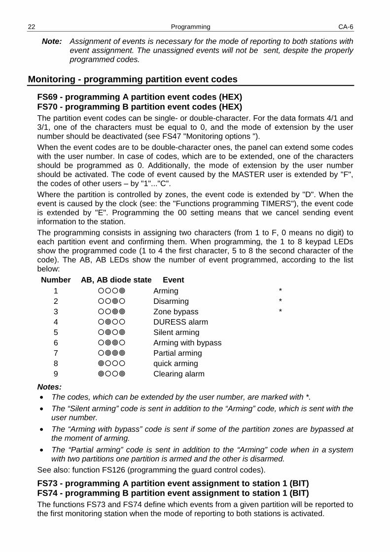
FS69 - programming A partition event codes (HEX) FS70 - programming B partition event codes (HEX) The partition event codes can be single- or double-character. For the data formats 4/1 and 3/1, one of the characters must be equal to 0, and the mode of extension by the user number should be deactivated (see FS47 "Monitoring options "). When the event codes are to be double-character ones, the panel can extend some codes with the user number. In case of codes, which are to be extended, one of the characters should be programmed as 0. Additionally, the mode of extension by the user number should be activated. The code of event caused by the MASTER user is extended by "F", the codes of other users – by "1"..."C". Where the partition is controlled by zones, the event code is extended by "D". When the event is caused by the clock (see: the "Functions programming TIMERS"), the event code is extended by "E". Programming the 00 setting means that we cancel sending event information to the station. The programming consists in assigning two characters (from 1 to F, 0 means no digit) to each partition event and confirming them. When programming, the 1 to 8 keypad LEDs show the programmed code (1 to 4 the first character, 5 to 8 the second character of the code). The AB, AB LEDs show the number of event programmed, according to the list below: Number AB, AB diode state Event 1 Arming * 2 Disarming * 3 Zone bypass * 4 DURESS alarm 5 Silent arming 6 Arming with bypass 7 Partial arming 8 quick arming 9 Clearing alarm
Notes: • The codes, which can be extended by the user number, are marked with *.
• The “Silent arming” code is sent in addition to the “Arming” code, which is sent with the user number.
• The “Arming with bypass” code is sent if some of the partition zones are bypassed at the moment of arming.
• The “Partial arming” code is sent in addition to the “Arming” code when in a system with two partitions one partition is armed and the other is disarmed.
See also: function FS126 (programming the guard control codes).
FS73 - programming A partition event assignment to station 1 (BIT) FS74 - programming B partition event assignment to station 1 (BIT) The functions FS73 and FS74 define which events from a given partition will be reported to the first monitoring station when the mode of reporting to both stations is activated.

CA-6 SATEL 23
Programming is carried out in two stages (the jump to the second set takes place after the [#] key is pressed). In the first set (the lower B LED is blinking), the events 1-8, to which LEDs 1-8 correspond, are programmed (as in FS69). In the second set (the lower A LED is blinking), the following events are programmed: guard round – LED 1, no guard round– LED 2, alarm clearance – LED 3.
FS77 - programming A partition event assignment to station 2 (BIT) FS78 - programming B partition event assignment to station 2 (BIT) The functions FS77 and FS78 define which partition events will be reported to the second monitoring station when the mode of reporting to both stations is activated.
Monitoring - programming system event codes
Apart from the events from zones and partitions, the CA-6 can show information on system events (mainly related to the detected troubles). The system event codes are programmed in the same way as the zone event codes.
FS81 - programming system event codes - set I (HEX) The function enables first fourteen system events to be programmed. The programming procedure is the same as in FS69 function. Number AB, AB diode state Event 1 AC loss 2 AC power restore 3 Battery trouble 4 Battery OK 5 OUT1 trouble 6 OUT1 trouble restore 7 OUT2 trouble 8 OUT2 trouble restore 9 OUT3 trouble 10 OUT3 trouble restore 11 Service mode - start 12 Service mode - end 13 DOWNLOADING - start 14 DOWNLOADING - end
FS82 - programming system event codes - set II (HEX) The function enables the system events of the second set to be programmed. The programming procedure is the same as in FS69. Number AB, AB diode state Event 1 keypad supply trouble 2 keypad supply trouble 3 Reporting trouble 4 Station buffer overflow 5 Clock loss 6 RAM memory error 7 Panel restart 8 Periodical reporting test 9 Clock setting * 10 Fire alarm (from keypad)

24 Programming CA-6
11 Panic alarm (from keypad) 12 Medical alarm (from keypad) 13 Alarm - keypad tamper 14 Alarm 3 incorrect codes
Notes: • The code 3 is recorded in the event log when the control panel is unable to establish
communication with the station. In that case, the control panel will retry after 60 seconds to establish connection. When it gets through, the control panel will transmit all the unsent events from the memory. The events are sent by the panel in order of their occurrence (the oldest event is sent first).
• The code 4 is recorded in the event log when lack of communication with the station lasted so long that all the memory intended for the events (255 events) has been filled up and the oldest events have been erased.
• The code 9 can be extended by the control panel with the user number.
FS83 - programming system event assignment to station 1 (BIT) When the mode of notifying both stations is active, it is possible to determine for most events, whether they will be transmitted to the station 1, station 2, or to both stations. The other system events are reported to both stations. The programming is a three-stage procedure, which consists in specifying events which are to be sent to the station 1. First stage - 1 to 8 LEDs show the following events (the lower B diode blinks):
1 - AC loss 2 - AC power restore 3 - Battery trouble 4 - Battery OK 5 - OUT1 trouble 6 - OUT1 trouble restore 7 - OUT2 trouble 8 - OUT2 trouble restore
Second stage - 1 to 6 LEDs show the following events (the lower A diode blinks): 1 - OUT3 trouble 2 - OUT3 trouble restore 3 - Service mode - start 4 - Service mode - end 5 - DOWNLOADING - start 6 - DOWNLOADING - end
Third stage - 1 to 5 LEDs show the following events (the A and B diodes blink): 1 - Fire alarm (from keypad) 2 - Panic alarm (from keypad) 3 - Medical alarm (from keypad) 4 - Alarm - keypad tamper 5 - Alarm 3 incorrect codes
FS84 - programming system event assignment to station 2 (BIT) The function makes it possible to select system events sent to the station 2, when the mode of reporting to both stations is active. The programming procedure is identical as in FS83.

CA-6 SATEL 25
FS85 - programming test transmission time (DEC) The function sets three time parameters which define the moments of sending the test transmission code to the monitoring station. The first parameter (two two-digit numbers: hours, minutes) enables the station to check if the control panel clock works properly. The mechanism sending the code every day at the same time can be disabled by programming a wrong time (for example, 99.99). The second parameter (three two-digit numbers: number of days, hours, minutes) defines the time counted from the last transmission to the station, after which test code will be sent by the control panel. After occurrence in the system of any event whose code will be sent, the panel starts counting the time again. This mechanism can be disabled by programming 00.00.00. The third parameter (three two-digit numbers: number of days, hours, minutes) makes it possible to program a separate period of the test transmission, valid only when the system is armed (for example, when more frequent test transmissions are needed during the armed mode). The control panel, when system is armed, calls the monitoring station every period of time specified in the given function. If a new event occurs and the panel sends its’ code to the monitoring station, then the countdown of the programmed time starts from the beginning. When 00, 00, 00 value is entered, then, irrespective of whether the control panel is armed or not, only the time programmed in FS 70 is used. The programming consists in entering five two-digit numbers. After confirmation of all the numbers, the panel exits the function. EXAMPLE: programming the test code to be sent at 1:45 (clock test) and after two hours since the
last transmission (communication test), communication test, when system is armed – every 15 min.
[12345] [#] - enter the service mode [8][5] [#] - call the function [0][1] [#] - enter the hours [4][5] [#] - enter the minutes of clock test time (sending the message) [0][0] [#] - enter the number of days, [0][2] [#] - enter the number of hours, [0][0] [#] - enter the number of minutes of the communication test time. [0][0] [#] - enter the number of days [0][0] [#] - enter the number of hours [1][5] [#] - enter the number of minutes of the communication test during arm mode and terminate
the function
Note: If the test transmissions are conducted frequently (e.g. every 10 – 15 min.), it is recommended to activate in function FS5 option number 5 of the first set. Thus preventing the events memory of the control panel from being quickly filled up, since only 3 successive events of the test transmission are then saved in memory of the control panel.
FS86 - programming the „AC loss” report delay (DEC) The function defines the time from the mains supply loss after which the panel will send an „AC loss” message to the monitoring station. The delay time is programmed in minutes, within the range from 01 to 99 minutes. The mains supply loss is signaled instantly in keypads and on the AC POWER LOSS indicator outputs (function 25).

26 Programming CA-6
Messaging – programming telephone number
FS87 - programming telephone number 1 (HEX) FS88 - programming telephone number 2 (HEX) FS89 - programming telephone number 3 (HEX) FS90 - programming telephone number 4 (HEX) The functions FS87 to FS90 are used to program the telephone numbers to which the control panel sends alarm messages. Each telephone number can have up to sixteen digits and special characters. The numbers are to be programmed in the same way as in the function FS4.
FS95 - programming assignment of partitions and messages (BIT) At the moment an alarm occurs, the control panel can send an alarm message to four telephone numbers. As the system can be divided into independent partitions, the messaging should depend on which partition is alarming. The FS95 function assigns the telephone numbers to partitions and defines which message is to be sent. To program this parameter it is necessary to assign partition and number of message, which is to be sent to each telephone number. The AB, AB LEDs indicate (in binary format) the telephone number, which is being programmed. The LEDs 1 and 2 show the assignment of consecutive numbers to partitions: 1 - telephone number for A partition 2 - telephone number for B partition A telephone number can be associated with one or two partitions. The LEDs 5 to 6 show the message, which is sent to a consecutive number: 5 - message 1 to pager 6 - message 2 to pager
Note: If no message for the paging system is assigned to the number, the panel will send a voice message from the synthesizer.
EXAMPLE: programming of the following settings (assuming that LEDs 1 to 8 for all numbers are off) ● 1st telephone number - message no. 1 (pager), in case of alarm in A & B partitions, ● 2nd telephone number - message no. 2 (pager), in case of alarm in A partition, ● 3rd & 4th tel. number - voice message from synthesizer, in case of alarm in B partition. [12345] [#] - enter the service mode [9][5] [#] - call the function (lower B diode is blinking - 1st telephone number) [1] - LED 1 goes on (number 1 assigned to A partition) [2] - LED 2 goes on (number 1 assigned to B partition) [5] - LED 5 goes on (message 1 assigned to number 1) [#] - confirm assignment for number 1 (A LED is blinking - 2nd number) [1] - LED 1 goes on (number 2 assigned to A partition) [6] - LED 6 goes on (number 2 assigned to B partition) [#] - confirm assignment for number 2 (A and B LEDs are blinking- 3rd number) [2] - LED 2 goes on (number 3 assigned to B partition) [#] - confirm assignment for number 3 (upper B LED is blinking - 4th number) [2] - LED 2 goes on (number 4 assigned to B partition) [#] - confirm assignment for number 4
Messaging – programming of PAGER messages
FS96 - programming message 1 (POLPAGER format) FS97 - programming message 2 (POLPAGER) The message is programmed in the same way as in case of direct telephone messaging to the POLPAGER receiver. The control panel saves in its memory the consecutively
CA-6 SATEL 27
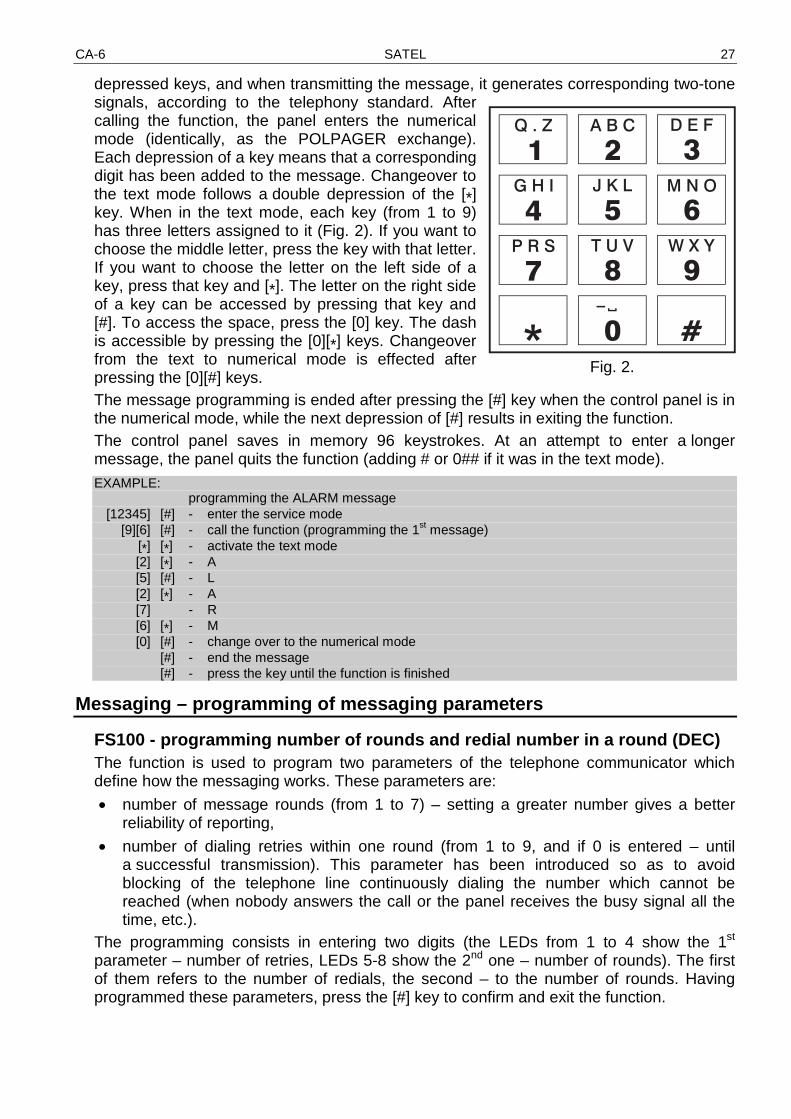
depressed keys, and when transmitting the message, it generates corresponding two-tone signals, according to the telephony standard. After calling the function, the panel enters the numerical mode (identically, as the POLPAGER exchange). Each depression of a key means that a corresponding digit has been added to the message. Changeover to the text mode follows a double depression of the [*] key. When in the text mode, each key (from 1 to 9) has three letters assigned to it (Fig. 2). If you want to choose the middle letter, press the key with that letter. If you want to choose the letter on the left side of a key, press that key and [*]. The letter on the right side of a key can be accessed by pressing that key and [#]. To access the space, press the [0] key. The dash is accessible by pressing the [0][*] keys. Changeover from the text to numerical mode is effected after pressing the [0][#] keys. The message programming is ended after pressing the [#] key when the control panel is in the numerical mode, while the next depression of [#] results in exiting the function. The control panel saves in memory 96 keystrokes. At an attempt to enter a longer message, the panel quits the function (adding # or 0## if it was in the text mode).
EXAMPLE: programming the ALARM message [12345] [#] - enter the service mode [9][6] [#] - call the function (programming the 1st message) [*] [*] - activate the text mode [2] [*] - A [5] [#] - L [2] [*] - A [7] - R [6] [*] - M [0] [#] - change over to the numerical mode [#] - end the message [#] - press the key until the function is finished
Messaging – programming of messaging parameters
FS100 - programming number of rounds and redial number in a round (DEC) The function is used to program two parameters of the telephone communicator which define how the messaging works. These parameters are:
• number of message rounds (from 1 to 7) – setting a greater number gives a better reliability of reporting,
• number of dialing retries within one round (from 1 to 9, and if 0 is entered – until a successful transmission). This parameter has been introduced so as to avoid blocking of the telephone line continuously dialing the number which cannot be reached (when nobody answers the call or the panel receives the busy signal all the time, etc.).
The programming consists in entering two digits (the LEDs from 1 to 4 show the 1st parameter – number of retries, LEDs 5-8 show the 2nd one – number of rounds). The first of them refers to the number of redials, the second – to the number of rounds. Having programmed these parameters, press the [#] key to confirm and exit the function.
Fig. 2.

28 Programming CA-6
FS101 - programming number of rings before answer (DEC) The function sets the number of rings after which the CA-6 control panel answers the call in order to report the alarm system status or to establish communication with the computer. The programming consists in entering a number from 01 to 15 and confirming it with the [#] key. Depending on how the answering option is set (the FS5 function, the second set of options), the control panel will answer the call immediately after detecting the programmed number of rings, or on the first ring detected after an interval lasting less than 5 minutes from detecting the programmed number of rings ("double call").
Notes: • Having answered a call in the "single call" mode, the panel will not answer any more
calls for about 5 minutes so as to enable access to other equipment connected after the panel (e.g. automatic answering system, fax/modem).
• When it is impossible to establish communication with the control panel by the computer, and the call answering is on, the control panel will only answer the calls when all defined partitions are armed.
Functions programming TIMERS
The CA-6 control panel is equipped with four TIMERS, which compare the panel clock with the times set on the TIMERS. If the times are consistent, the timers perform the functions assigned to them.
FS102 - programming TIMERA 1 (DEC) The function defines the TIMER 1 ON/OFF hour and minute. The programming consists in entering four two-digit numbers, the first two denoting the ON time (hour, minute), and the other two the OFF time (hour, minute). If you want to program the ON or OFF time only than set one of the times at 99:99 value.
EXAMPLE: programming the TIMER 1: ON time - 16:30, OFF time - 06:30 [12345] [#] - enter the service mode [1][0][2] [#] - call the function [1][6] [#] - program the ON time hours (B LED is blinking) [3][0] [#] - program the ON time minutes (A LED is blinking) [0][6] [#] - program the OFF time hours (A & B LEDs are blinking) [3][0] [#] - program the OFF time minutes and exit the function (B LED is blinking)
FS103 - programming TIMERA 2 (DEC) FS104 - programming TIMERA 3 (DEC) FS105 - programming TIMERA 4 (DEC) FS106 - programming TIMER functions (DEC) The function defines how the timers are used. They can control outputs or partitions. The programming consists in entering four characters from 0 to 9 (2× two characters). The first character defines the TIMER 1 function, the second - TIMER 2, the third - TIMER 3, and the fourth - TIMER 4.
Note: The outputs indicated in this function, irrespective of their type, are controlled by TIMER – as distinct from the CA-10 control panel, where the timers control only the TIMER type outputs.
TIMER functions: 0 - TIMER not used 1 - controls output OUT1 2 - controls output OUT2

CA-6 SATEL 29
3 - controls output OUT3 4 - controls output OUT4 5 - controls output OUT5 6 - not used – do not program 7 - partition control timer (guard rounds) 8 - controls A partition 9 - controls B partition
Note: Do not program the values 6 and A to F. The partition control function (7) can only be programmed for timer 1 (A partition control) and timer 2 (B partition control).
The Guard rounds control requires the following parameters: • guard code in the controlled partition (a code with authority level 5 – it also performs
the function of activating the MONO SWITCH).
• partition control timer – the hour and minute set for switching on this timer defines the maximum time that may elapse since the last time the guard code was entered - if it is exceeded, the “no control code” event is recorded in the memory, the information is sent to the monitoring station, and the “no guard round” type output is activated. Entering the code by the guard is recorded in the event memory as the “entry/exit” event.
EXAMPLE: programming the function: TIMER1 - controls A partition, TIMER 2 - controls OUT4
output, TIMER 3 and TIMER 4 - control OUT5 output. [12345] [#] - enter the service mode [1][0][6] [#] - call the function [8][4] [#] - program the timers 1 and 2 functions (B diode is blinking) [5][5] [#] - program the timers 3 and 4 functions (A diode is blinking) and exit the function
Special functions
FS107 - restoring default settings Calling this function will restore all the factory default settings of the control panel parameters (see: „Default settings” section, Installer Instruction) and will automatically read the current address of the keypads. The service code is set as [1][2][3][4][5]. The function does not change the user access codes.
FS108 - clearing event log Calling this function will erase the memory of events.
FS109 - restoring default communication passwords Calling this function will restore the factory default control panel and computer identifiers (see: FS2, FS3), which are required to establish communication with the computer. These settings are used for testing the control panel.
FS110 - restoring default codes Calling this function will erase all the user access codes and restore the default MASTER code [1][2][3][4] and the default service code [1][2][3][4][5].
FS111 - programming keypad address (BIT) The keypad of CA-6 control panel has its individual address, which is set with jumpers. The panel imports this address together with other keypad data (zone state, depressed keys, tamper contact state) and compares with the address programmed in the nonvolatile memory. If a difference is detected, a tamper alarm is triggered.

30 Programming CA-6
The keypad with incorrect address is not supported by the control panel. The address is not controlled, when the panel is in the service mode. The keypad address is set by the control panel automatically when the default settings are being programmed (the panel reads out setting of the jumpers and stores it in memory). The FS111 function enables to check the keypad address and program it. It is necessary that the same address would be also set by means of the jumpers. It means that the address set on the keypad pins and the one programmed with this function must be identical. The programming in FS111 function consists in lighting up the LEDs 1 to 4, which correspond to the jumper settings. The settings need to be confirmed with the [#] key. The [*] key enables to quit the function.
Fig. 3. Setting of the jumpers and corresponding LEDs during programming procedure in the CA-6 KLED keypad.
Notes: • The control panel does not support keypad in which either all jumpers or no jumpers
are set.
• When programming the keypad address be particularly careful, as having programmed a wrong address may trigger a tamper alarm at the moment you exit the service mode and cause a loss of control from the keypad. Then it is necessary to enter the service mode by hardware means and read the new address (see: Installer Manual).
• The new address (as most of the programmed parameters of the panel) will become valid after exiting the service mode or when the panel is being programmed from the computer - after the data are sent.
Automatic readout of the keypad address without changing the other control panel parameters is possible by means of the FS124 function.
FS112 - start of programming from computer in local mode The function starts the programming mode through a modem or RS-232 TTL port. The function is called upon a prompt from the computer. Prior to using the function, hook up the control panel to the computer (see: Installer Manual). Start the DLOAD10 program on the computer. After calling the function, the panel will first try to establish connection through the RS port, and if fails, via the telephone line.
address

CA-6 SATEL 31
Start programming through RS-232 The function starts the mode of control panel programming through the RS-232 interface. Prior to calling the function:
• connect the control panel to the computer with the special cable (see: INSTALLER
MANUAL, chapter: DESCRIPTION OF CONTROL PANEL MAIN BOARD, description of the RJ socket);
• start the DLOAD10 program in the computer and select the number of communication port (COM);
• open the menu „Communication” and select the „RS-232” item, and then „Local connection with…” (select the CA-6 control panel);
• select the service mode in the control panel and start the FS112 function. If the control panel receives no dial tone from the computer within 10 seconds (wrong computer connection cable or port number), the function will quit automatically.
Programming with the use of modem Before calling the function:
• connect the modem to the control panel;
• start the DLOAD10 program in the computer and select the number of communication port (COM);
• open the menu File, item →„Open...” or →„New”, and select the control panel →„CA-6"; open the menu Communication and select→„Modem"; and, in the „Modem initialization” window, select →„Local connection with” – the computer will ask you to call the FS112 function.
The control panel can also be programmed without calling Function FS112 in the keypad (see: Installer Manual). After calling the FS112 function (just as in case of the other service functions) the
[TROUBLE]. LED is on and the control panel tries to establish communication with the computer. If it fails within about 20 seconds, the panel exits the function signaling an error (two long beeps). When the communication is established (four short and one long beeps), the control panel exits the function to the service mode. The online communication is maintained until a corresponding command is received from the computer. More information is given in the Installer Manual.
FS117 - telephone line trouble delay (DEC) The function defines how many minutes may elapse from the low voltage condition on the telephone line to the moment the panel reports a trouble. Lifting the handset of a telephone connected to the same telephone line is also recognized as a telephone line loss. The programming consists in entering a two-digit number from 00 to 99 minutes. If 00 is programmed, the panel never reports the telephone line voltage trouble.
EXAMPLE: programming a twenty-minute delay [12345] [#] - enter the service mode [1][1][7] [#] - call the function [2][0] [#] - program the delay
FS118 - parameters of pager station signals (HEX) The function defines parameters of the answer signals generated by automatic pager station. As different answer signals are used in each system, it is necessary to specify the signal parameters of the system to which the panel transmits its messages. If parameters of such signals change, it will be sufficient to specify new data.

32 Programming CA-6
The programming consists in entering six two-character codes which are suitable for the given paging system. The particular systems should be programmed as follows:
• POLPAGER - [118]# [3B]#[42]#[0B]#[0F]#[01]#[7D]#
• TELEPAGE - [118]# [2B]#[2E]#[0E]#[14]#[30]#[3A]#
• EASYCALL - [118]# [37]#[3D]#[07]#[0B]#[B6]#[C8]#
• METROBEEP - [118]# [16]#[1A]#[13]#[17]#[0B]#[0F]#
FS123 - counter count-up times (DEC) The function makes it possible to program time intervals related to the counters 1, 2 and 3 of counting zones. The alarm will be generated only if the number of violations preset in FS7 function takes place within the time interval defined by this function. The count-up times may be programmed within the interval from 1 to 255 seconds (by default set at 30 seconds). If the number of violations programmed in the FS7function does not take place within the time interval defined in the function, after expiry of the time the counting zones counters will be reset. After starting the function, you should enter one, two or three digits for the first counter. Upon confirmation with the key [#], the control panel proceeds to programming the count-up time of the next counter. In the course of programming, the AB, AB LEDs indicate (in binary format) the counter number. On the LEDs 1-8, the control panel displays the previously programmed setting of the parameter in the binary format (the introduced changes will be only displayed after the function is reentered). The programming can be terminated by pressing the [*] key.
EXAMPLE: changing the counter count-up time: the first one – 60 seconds, the second – 150
seconds, the third – 255 seconds, [12345] [#] - enter the service mode [1][2][3] [#] - call the function [6][0] - enter the first counter time (B LED is blinking during programming) [#] - confirm the counter 1 count-up time and proceed to programming counter 2 [1][5][0] - enter the second counter time (A LED is blinking during programming) [#] - confirm the counter 2 count-up time and proceed to programming counter 3 [2][5][5] - enter the third counter time (A & B LEDs are blinking during programming) [#] - confirm the counter 3 count-up time and quit the function
FS124 - automatic readout of keypad address The function enables the keypad address to be automatically read without changing the other parameters.
FS125 - programming CTL input functions (HEX) The CTL control input of the CA-6 panel can perform one of the following functions: 0 – not used, 1 - arming, 2 - disarming, 3 - FIRE alarm, 4 - PANIC alarm, 5 - alarm AUX, 6 - arming / disarming, 7 - alarm cancelling (no disarming). Two digits are programmed. The first of them defines the input function (from 1 to 7), the second defines which partition should be armed, disarmed or in which partition should be cleared an alarm. 0 - for functions: FIRE alarm, PANIC alarm, alarm AUX,

CA-6 SATEL 33
1 - arming / disarming or cancelling alarm – A partition, 2 - arming / disarming or cancelling alarm – B partition, 3 - arming / disarming or cancelling alarm – A & B partition.
Note: Do not program any values beyond the permissible.
The input responds to shorting to ground (approx. 0.5 sec.). For example, if function 6 (Arm/Disarm) has been programmed, the partition will be armed on shorting to common ground, and disarmed on breaking the ground connection and shorting to ground again The input violation generates the following event codes: • for input functions 3,4 or 5 - codes of keypad alarms programmed with function FS82, • for the other functions - codes of arming or disarming (alarm clearing) by the input with
„D” extension (programmed with functions FS69 and FS70). FS126 - programming guard control codes (HEX) Four event codes are programmed in the following order:
• entry/exit A partition (enter control code – A partition) – the lower B LED is blinking,
• entry/exit B partition (enter control code – B partition) – the lower A LED is blinking,
• no control code in A partition – the A and B diodes are blinking,
• no control code in B partition – the upper B diode is blinking. The programming of the partition control codes is similar to the programming of the FS69 and FS70 functions. If the "entry/exit" codes are one-digit numbers and the respective option is on (see: FS47), they can be automatically extended by the user number.
FS127 - zones bypassed on no exit from A partition (BIT) FS128 - zones bypassed on no exit from B partition (BIT) The EXIT-BYPASS service functions 127 and 128 make it possible to program for each partition the zones which will be automatically bypassed if, after arming, there is no violation of the ENTRY/EXIT type zone during the exit delay (after arming the system, the user has not left the site and has not violated any detector in the ENTRY/EXIT type zone. The programming is similar to the programming of the FS16 and FS17 functions.
FS131 - programming additional options (BIT) FIRST SET OF THE OPTIONS (the lower B diode is blinking)
No. LED Option ON hardware entering service mode blocked
1 OFF hardware entering service mode enabled
ON hardware start of downloading disabled 2
OFF hardware start of downloading enabled
ON pulse dialing ration 1:1,5 3
OFF pulse dialing ration 1:2
ON remote control module (MST-1) supported 4
OFF remote control module (MST-1) not supported
Option 1 refers to disabling the hardware access to the service mode. If this option is selected, it is only possible to enter the service mode by using the service access code. The procedure of entering the service mode when the service code has been lost and the possibility of starting the service mode by hardware means (jumpers) is disabled is described in the Installer manual, in section: Entering service mode “from pins”. Carrying out the procedure will result in the loss of all settings.

34 Programming CA-6
Option 2 refers to blocking the programming of control panel settings in the local mode by means of modem, which does not require the control panel being operated from the keypad, i.e. calling function FS112. Option 3 refers to the control panel dialer and defines the pulse dialing ratio during pulse dialing of a telephone number. Selecting the option sets its value at 1:1.5. If the option is not selected, the ratio is 1:2. Option 4 refers to the panel work with the module that enables the panel to be operated via a telephone generating DTMF signals. For such a work to be possible, it is necessary to activate the option 3 from the first set in FS5 („telephone answering”).
SECOND SET OF OPTIONS (the lower A LED is blinking)
No. LED Option ON disable arming if battery trouble
1 OFF arming during battery trouble enabled
ON automatic clearing zone Auto-Reset at midnight (00:00) 2
OFF do no reset bypassing of zones with AUTORESET 1/3 option
Option 1 disables the possibility of arming, if the control panel has detected a battery trouble. When selected, the option 2 will reset the counters of the zones bypassed after 1 or 3 alarms at 00:00 hour.
FS132 - programming clock correction (DEC) As time measurement by the control panel internal clock may differ from the real value, provision has been made for making a daily time correction. The function makes it possible to correct the time measurement by ±19 seconds within 24 hours. For programming the time correction, use the function FS132 to enter the value of daily time shift of internal clock: The programming consists in entering two digits, according to the magnitude of expected correction (see the table below).
Clock correction [s] -19 -18 -17 ... -2 -1 0 1 2 ... 17 18 19 LED programming 99 98 97 ... 82 81 00 01 02 ... 17 18 19
EXAMPLE: program the time correction as “-12 seconds”. [12345] [#] - enter the service mode [1][3][2] [#] - call the function [9][2] [#] - enter the correction value (minus 12 seconds).
FS133 - reviewing control panel real-time clock (no change possible) After calling the function, the LEDs 1 to 8 shows the real time hour (two digits in binary format), LEDs 1-4 shows the first digit, LEDs 5-8 - the second digit. EXAMPLE: 13.00 p.m. 1 2 3 4 5 6 7 8
In order to check the other indications of the clock and calendar, press the appropriate keys on keypad:
1. hours, 2. minutes, 3. seconds, 4. days, 5. months, 6. years (two last digits).
Use the [#] or [*] key to terminate the function

CA-6 SATEL 35
Restoring default settings, erasing codes
There are three ways to restore the factory settings: 1. Restore the settings after entering the service mode by means of the service code. Having
entered the service code, call function FS107 (restores all factory settings, except for user codes) and function FS110 (restores the master user code, all the other user codes being deleted). You can also perform function FS108 (to reset the event memory).
2. Restore the settings after entering the service mode „from pins” (if the service code has been lost). Having entered the service mode „from pins” (see the Installer Manual), you have to call Functions FS107 and FS110. You can also execute Function FS108. The entering the service mode „from pins” alone will not restore any settings.
3. Restore the settings when the service mode „from pins” is blocked (FS131) and it is impossible to enter it by using the service code. For description of the procedure refer to the Installer Manual, section: Entering service mode „from pins”. After the procedure is completed, the control panel will automatically restore the factory settings and start the service mode. In order to restart the user codes, call FS110.
History Of Manual Updates
The changes described refer to the manual drawn up for the CA-6 v5.05 control panel.
DATE VERSION DESCRIPTION OF CHANGES
June 2007
6.06
Possibility of programming the special characters (*, #, a, b, c, d) in the telephone number has been added (p. 7). Arming is impossible, if the zone with activated PRIORITY option is violated or tampered (p. 14). Description of the zones sensitivity indication by the LED keypads has been added (p. 12). A new parameter which enables to set a separate time of the test transmission when system is armed (p. 25) and a new option „only 3 test transmission events” (FS 5, option no. 5 of the first set, p. 8) have been added. A new cable for programming the control panel from the computer is necessary (p. 31).

Appendix – CA-6 List of Events
The table contains event names and information on extendability of the event code. Shown in a separate column are codes in the Contact ID (CID) format and information on the 0E format (Contact ID selected codes – see description of the functions FS45 and FS46).
No. Events - Zones Extendable by the number of:
CID code 0E format
1. Zone alarm zone 1,110 1,130 1,150 1,122 1,134 1,123 1,135
2. Zone tamper alarm zone 1,144 1,373 3. Violation on „autoreset” zone 4. Zone restore zone 5. Tamper restore zone 3,144 3,373 6. DAY/NIGHT zone violation zone 1,135 7. Zone violation zone
Events – A and B Partitions 1. Arming user 3,401 2. Disarming user 1,401 3. Zone bypass user 1,574 4. Alarm DURESS user (CID only) 1,121 5. Silent arming 6. Arming with zone bypass 7. Partition arming 8. Quick arming 3,408
9. Guard code used (MONO SWITCH)
10. No guard code 1,126 11. Alarm clearing user (CID only) 1,406

No. Events - System Extendable
by the number of: CID code 0E format
1. Telephone line trouble 2. Telephone line restore 3. Clock loss 3,625 no assignment 4. AC power loss 1,301 5. AC power restore 3,301 6. Test transmission 1,602 no assignment 7. Battery trouble 1,302 8. Battery OK 3,302 9. OUT 1 overload 1,320 (1) 10. OUT 1 OK 3,320 (1) 11. OUT 2 overload 1,320 (2) 12. OUT 2 OK. 3,320 (2) 13. OUT 3 overload 1,320 (3) 14. OUT 3 OK. 3,320 (3) 15. Reporting trouble 1,350 no assignment 16. Service mode start 1,627 17. Service mode end 1,628 18. External DOWNLOADING start 1,410 19. DOWNLOADING end 1,412 20. RAM memory error 1,303 (0) no assignment 21. Panel restart 1,305 no assignment 22. Keypad power trouble 1,320 (4) no assignment 23. Keypad power restore 3,320 (4) no assignment 24. OUT 1 no load 1,320 (1) 25. OUT 1 load restore 3,320 (1) 26. OUT 2 no load 1,320 (2) 27. OUT 2 load restore 3,320 (2) 28. OUT 3 no load 1,320 (3) 29. OUT 3 load restore 3,320 (3) 30. Buffer overflow - station 1 1,624 (1) no assignment 31. Buffer overflow - station 2 1,624 (2) no assignment 32. DOWNLOAD start 1,410 33. EEPROM memory error 1,303 (1) no assignment 34. Keypad FIRE alarm 1,115 35. Keypad PANIC alarm 1,120 36. Keypad AUX alarm 1,100 37. Keypad tamper alarm 1,145 38. 3 wrong codes alarm 1,461 39. Time programming user 1,625

Character Encoding Table for LED Keypads
Decimal format (DEC) Binary format (BIT) Hexadecimal format
(HEX)
State of LEDs:
1 2 3 4
5 6 7 8
A B A B
0 0000 0
1 0001 1
2 0010 2
3 0011 3
4 0100 4
5 0101 5
6 0110 6
7 0111 7
8 1000 8
9 1001 9
10 1010 A
11 1011 B
12 1100 C
13 1101 D
14 1110 E
15 1111 F
SATEL sp. z o.o. ul. Schuberta 79 80-172 Gdańsk
POLAND tel. +48 58 320 94 00
[email protected] www.satel.pl