progress report spring 2015-16 final noresumes
TRANSCRIPT

PROGRESS REPORT Spring 2015-2016
Team Number ECE-BCC-4
Paintball Environment Tactical Engagement Recon System (P.E.T.E.R.S.)
Team Members
Name Department Email Richard Taylor Anthony Schmidt Kenneth Hale Antonio Foster Brett Reich
ECE ECE ECE ECE ECE
[email protected] [email protected] [email protected] [email protected] [email protected]
Team Advisor(s)
Name Department/Company Email Christopher Peters ECE [email protected]
Group Leader's Signature : Richard Taylor __ Advisor's Signature : _________Dr. Peters _____
2
1. Abstract The game of paintball has existed in one form or another for roughly the last 30
years, and in that time it has grown from a small group of friends engaging in archaic, backyard games to a full-fledged multi-million dollar-a-year industry. As a result, many great technological strides have been made in terms of improving the paintball marker, playing field, and peripheral development, but the tactics employed on the simulated battlefield and the derived annoyances that accompany them have remained largely unchanged over the years. For any seasoned paintball enthusiast, it is no secret that checking paint levels, pressurized air levels, and determining the location of teammates all involve a large diversion of attention from the task at hand and can each, in their own ways, contribute to the loss of the game. Currently, however, there is simply no work-around for keeping one’s attention totally dedicated to the game and its resulting, dynamic environment.
The Paintball Environment Tactical Engagement Recon System (P.E.T.E.R.S) aims to significantly lessen or totally remove these distractions by placing the required information in the peripheral vision of the user. By way of utilizing existing commercial-off-the-shelf (COTS) hardware and developing a system of network communication, this project aims to make available to the user information regarding paint level, remaining air pressure, and relative player locations in the form of a heads-up display (HUD) integrated into the paintball mask. In this way, the user can maintain a ready posture at all times in terms of directing the majority of attention to his/her surrounding environment and thereby able to react far more readily to the bevy of situations encountered during a game.

3
Table of Contents 1. Abstract ........................................................................................................................... 2
List of Figures ..................................................................................................................... 4
2. Problem Description ....................................................................................................... 6
3. Proposed Work and Deliverables.................................................................................... 8
3.1 Solutions considered ................................................................................................. 8
3.1.1 Hardware Considerations ................................................................................... 8
3.1.2 Software Considerations .................................................................................... 9
3.2 Unique Principles .................................................................................................... 10
3.3 Existing Systems ..................................................................................................... 11
3.4 Criteria for Acceptable Solution ............................................................................. 11
3.5 Work Flow Diagram ............................................................................................... 12
3.6 System Flow Diagram............................................................................................. 13
4. Completed Work ....................................................................................................... 14
4.1 – Hardware .............................................................................................................. 14
4.1.1 – Fall Progress.................................................................................................. 14
4.1.2 – Winter Progress ............................................................................................. 15
4.1.3 – Spring Progress ................................................................................................. 15
4.2 – Software ............................................................................................................... 17
4.2.1 – Fall Progress.................................................................................................. 17
4.2.2 – Winter Progress ............................................................................................. 17
4.2.3 - Spring Progress .............................................................................................. 18
4.3 – Testing and Validation ..................................................................................... 19
5. Work Schedule / Proposed Timeline ............................................................................ 21
6. Industrial Budget ........................................................................................................... 22
7. Out-of-Pocket Budget ................................................................................................... 23
8. Societal, Environmental or Ethical Impacts .................................................................. 24
9. Summary/Conclusions .................................................................................................. 25
10. References ................................................................................................................... 26
Appendix A: Design Constraints Summary ..................................................................... 27
Appendix B: Addressing Comments from the Panel ........................................................ 29
Appendix C: Individual Contribution to the Project ......................................................... 30
Appendix D: Quad Chart .................................................................................................. 31
User Guide ........................................................................................................................ 32

4
List of Figures Figure 1 – Typical Paintball Hopper ................................................................................... 6
Figure 2 – Marker-Mounted Tank Setup and Remote-Line Tank Setup ............................ 7
Figure 3 – Recon Snow2 HUD ........................................................................................... 9
Figure 4 – Honeywell Pressure Sensor ............................................................................... 9
Figure 5 – Ultrasonic Sensor............................................................................................... 9
Figure 6 – Overall Software Architecture Design ............................................................ 10
Figure 7 – Work Flow Diagram ........................................................................................ 12
Figure 8 – System Flow Diagram ..................................................................................... 13
Figure 9 – Pressure Sensor Locations ............................................................................... 14
Figure 10 – Pressure Sensor Data ..................................................................................... 15
Figure 11 – SolidWorks Model......................................................................................... 16
Figure 12 – 3D Printed Hopper Attachment ..................................................................... 16
Figure 13 – SolidWorks Model......................................................................................... 16
Figure 14 - 3D Printed Air Tank Attachment ................................................................... 16
Figure 15 - Hopper Attachment Schematic ...................................................................... 16
Figure 16 - Air Tank Attachment Schematic .................................................................... 17
Figure 17 - HUD GUI Scope ............................................................................................ 18
Figure 18 - Battery Life Cycle .......................................................................................... 20
Figure 19 – Project Timeline ............................................................................................ 21
Figure 20 - Industrial Budget ............................................................................................ 22
Figure 21 – Industrial Budget ........................................................................................... 22
Figure 22 – Fall Out-of-Pocket Budget ............................................................................ 23

5
Figure 23 – Winter Out-of-Pocket Budget........................................................................ 23

6
2. Problem Description
Anyone who has participated in a game of paintball understands that it is fast, chaotic, and at times incredibly intense. Paintball is designed to mimic objective-based combat scenarios with all players equipped with pressurized air-powered markers that expel paint-filled, spherical membranes designed to break on impact. As with any chaotic situation, those who are able to channel their energy and focus properly are typically the ones who succeed, and this is especially true in paintball. Any action that detracts a player’s attention away from the game, whether it is for a legitimate reason or otherwise, creates a window of opportunity, however small or large, for the opposing team to gain the upper hand by either removing players from the game or gaining a tactical advantage by gaining ground.
During a game of paintball, there are various inconveniences that arise out of the very nature of the game and the equipment used to play it. These inconveniences inevitably force the player to divert their attention away from the game. Two of these annoyances in particular involve the most vital components of the game itself: paintballs and pressurized air. More often than not, gaining “battlefield” information on these two resources involves removing oneself from the action altogether, if only for a few seconds at a time. Yet another major distraction is the constant guess-work with respect to where teammates are currently located. This is a considerable tactical disadvantage.
Throughout a typical round of paintball, a player must maintain an awareness of the amount of paintballs left in the hopper (Figure 1) and oftentimes the only way to do this is to physically lift the lid and peer inside of the loader. This involves two actions: first, the player must either alter his/her posture or move the marker out of the firing position to facilitate viewing the inside of the hopper, and second, the lid must also be lifted. Even with so-called quick-load or clear lids which essentially remove the second action, the initial action removes a player’s attention from the action unfolding around him/her.
Figure 1 – Typical Paintball Hopper
Another piece of critical information is the current level of pressurized air available to the paintball marker. This importance stems from a player’s ability to plan ahead in terms of the number of shots they have remaining based on air in the tank. Traditionally, the pressurized tank supplying the marker is connected directly to the marker itself as shown in Figure 2 (left image); in this case the tank doubles as both the air source and a buttstock of sorts to anchor the marker to the player. An increasingly larger number of players are opting for a remote-line setup as pictured in Figure 2(right image) where the tank is connected to the marker via an umbilical airline and is carried on the player’s body. The issue here is very similar to the issue presented in determining the paint level in the hopper: the player must divert attention away from the game in order to determine how much air remains in the tank. This issue is exasperated when the player is rigged into a

7
remote-line configuration as the tank is now separated from the marker and, depending on where the tank is physically located on the player’s person, the player may require secondhand assistance to ascertain a pressure reading.
Figure 2 – Marker-Mounted Tank Setup and Remote-Line Tank Setup
Perhaps the biggest distraction on the field for the paintball enthusiast comes from trying to determine where teammates are located. A typical snapshot during a paintball match will capture at least one player trying frantically to determine where his/her teammates are located. Traditionally, paintball players have relied on shouting back and forth, trying to get a feel for where everyone is currently positioned. The fact is that two players at opposite ends really have no idea where they are relative to one another if at all, and this can lead to tactical mistakes. The time a player takes to reacquaint him/herself with the location of teammates can very quickly turn into several seconds and result in losing situational awareness. There is a lot of effort being spent trying to ascertain very basic information, and this can create an opportunity for the opposing team to exploit. These three issues in particular have plagued the paintball community for years, and while various tools or products have been developed and marketed to ease the impact of any one of them on the game, there is currently no product on the market that supports a solution for all three in one package. A peripheral that would consolidate all of this pertinent information into one convenient package, providing a way for players to maintain their focus on the action all around them. In this game, sustaining alertness and adapting quickly to an ever-changing environment is the key to winning, and the goal of this project is to promote the removal of significant obstacles.

8
3. Proposed Work and Deliverables
3.1 Solutions considered
3.1.1 Hardware Considerations
When the concept for P.E.T.E.R.S. was first imagined, Google Glass was thought to be the best solution for a heads up display. Google is known for putting out open source products and encourages its users to modify or “hack” them to suit their needs and share what has been accomplished with others. After Google’s release of Glass it became evident that the product didn’t resonate with the public and was quickly removed from the shelves, along with all of the support for the product. This was the deciding factor that took the product out of consideration for this project. Needing a new solution for a HUD, Recon Instruments’ Snow2 HUD was found to be a perfect fit for the requirements of the P.E.T.E.R.S (Figure 3). This product has been created specifically for the purpose of relaying information to those participating in alpine sports. The Snow2 HUD is a module designed to function as in insert for ski/snowboard goggles which have a very similar ergonomic design with respect to paintball masks. It features a 428x240 LCD display, 9-axis sensor complement, Kalman filter algorithm-enhanced GPS networking, WiFi, Bluetooth 4.0, and has an Android operating system (OS). It is also an open-platform and has an associated software development kit (SDK) to facilitate application development.
With a HUD selected for the project, a solution to data processing and storage is next to be considered. The Raspberry Pi-2 single-board computer has been selected to function as the data and network server because it supports any language, has more than enough processing power to support the required application, is relatively low-cost, and lends itself well to any design changes that may need to be made later on in the design process. With solutions found for storing, processing, and displaying the data, hardware was evaluated for the purpose of collecting the data. Several pressure sensors were considered to collect data on a user’s available air pressure. Eventually the Honeywell MLH05KPSL06A was chosen for its durable construction and range of operating pressure (Figure 4). For collecting data on the paint levels a player has available to them, a few solutions were proposed. One solution was to gather information on the number of paintballs entering the hopper, and to track how many paintballs were leaving the barrel through counting the number of shots fired during the course of the day. This solution proved too difficult to implement as there is no reliable way of knowing how many paintballs a player was adding to the hopper at any given time. Another solution saw to give the player the ability to “tell” the system how many paintballs he/she was adding at any given time, in conjunction with the solution above. However, this seemed like it would be a nuisance to the user, and was found to be undesirable. Yet another solution considered used a series of laser diodes and photo-resistors on the interior of the hopper to monitor the paint levels in real-time. Even though this solution showed promise from a feasibility stand point, implementation of such a system would require a great deal of unnecessary work and for this reason was voted out. Ultimately the use of an ultrasonic sensor (Figure 5) in conjunction with an accelerometer and gyroscope, for measuring the orientation of the

9
marker, mounted directly on top of the hopper was selected as it meets all of our criteria and can be implemented easily.
3.1.2 Software Considerations In discussing the software design options that were available, it was absolutely understood that a balance must be struck between flexibility, performance, and portability. In an attempt to plan ahead with regards to possible unforeseen design flaws or other obstacles of a similar nature, the decision was made early on in the preliminary design process that the software would be written in Python. The driving reason for this is the fact that Python is an interpreted language and, as such, it can easily be ported to other devices should unforeseen issues with the current hardware suite be encountered. Third-party tools and utilities have been developed in the past few years that facilitate a much easier packaging of Python applications for usage in Android devices. Kivy is a community-driven project that has developed its own open-source Python library that facilitates GUI design which translates well to the Android platform. They have also developed a custom Android package (APK) build tool referred to as “python-for-android” which facilitates Python interpreter compilation, library inclusion, and fully-customizable distribution creation. On top of all of this, the Kivy organization provides a pre-built virtual machine archetype which is preconfigured to accommodate everything needed to create a GUI application in Python and then package it for delivery to an Android device. The Python language has a large amount of optimized and professionally authored library collections which as project development continues over the next several months will help with the more complicated coding. These characteristics of Python will hopefully lessen the time it takes to achieve a fully functioning software product. Since facilitating the maximum amount of flexibility in terms of software is a key facet of this project, a modular approach to software architecture is being stressed. This will allow greater ease in distributing portions of the overall application across a number of different hardware configurations if the need arises. Shown in Figure 6 is the overall software architecture that has been adopted and all framework has been modeled on. The main software components are the data-access layer storage (black border) which will house all data that is pertinent to the user and the system, the presentation layer display interface (green border) which will display the appropriate data for the user, the sensor data
Figure 3 – Recon Snow2 HUD
Figure 4 – Honeywell Pressure Sensor
Figure 5 – Ultrasonic Sensor

10
processing and updating module (blue border) which will be responsible for retrieving information from all peripheral sensors, and the external network data interface (red border) which will control communications with the other users in the field.
Figure 6 – Overall Software Architecture Design
To provide a clean, uncluttered network message-passing paradigm, the usage of the JavaScript Object Notation (JSON) formatting has been adopted. This will provide uniform, straightforward network message traffic and will be utilized as the communication format between all hardware and software modules. As the JSON data formatting is language-independent, it will fit nicely with the desire to remain flexible and responsive to any design changes that may occur.
3.2 Unique Principles As the Recon Snow2 HUD ships with a built in GPS, accelerometer, Bluetooth, and display screen, the amount of hardware needed to succeed is kept low and concentrated, and the project focus can be shifted to concentrate more specifically on the software needed to achieve the project’s goals. Recon Instruments’ Snow2 HUD leverages Android’s API heavily for their product which allows interaction with their suite of onboard sensors. The availability of these tools from the start allows for spending far less time ensuring that accurate data is being collected and more time developing the graphical user interface (GUI) and a networking system of communication.

11
This particular HUD model also serves the project well in that it is designed to be glanced at for short periods of time; the emphasis is on discrete delivery of desired data to the user in an unobtrusive manner that discourages focus on the screen. This system is designed for people on the move, and as such it is designed to be situated in a person’s peripheral vision so that deliberate movement of the viewing eye is required to see the screen. As in alpine sports, a paintball player should not be forced to look at a screen at all times; a screen projected onto the inner lens of the mask itself would prove to be a large distraction when actively searching for camouflaged individuals in a wooded environment. In line with this notion, the fact that this HUD is designed to remain out of sight until needed makes it ideal compared to other display types.
3.3 Existing Systems Regarding the sport of paintball specifically, there is not currently any kind of manufactured peripheral on the market that will report information to the user regarding paintball levels, pressurized air levels, and teammate location on a map. However, the Snow2 HUD itself has a similar alpine trail map and friend location feature by the use of a specific HUD app and allows third-party apps. All of the other hardware being utilized for this project include the Raspberry Pi and pressure sensors are used in many applications around the world, but there is currently no hardware/software configuration that is supporting the overall deliverables of this project.
3.4 Criteria for Acceptable Solution If this to be an acceptable solution, the final product must provide the following services at a minimum:
1. Allow player to view his/her location and his/her teammates’ locations in terms of position relative to the other players on the team.
2. Provide the player with a visible alert that the air pressure remaining in the tank has reached a low point.
3. Provide the player with a visible alert that the amount of paintballs remaining in the hopper has reached a low point.

12
3.5 Work Flow Diagram
Figure 7 – Work Flow Diagram
13
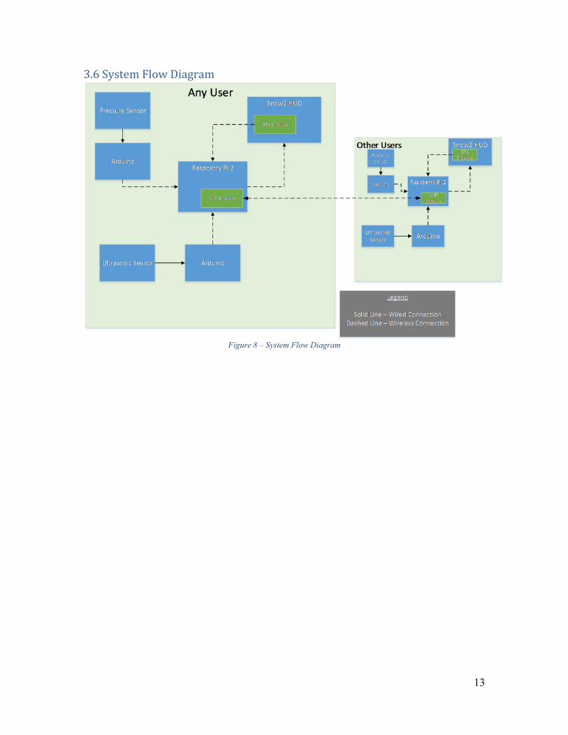
3.6 System Flow Diagram
Figure 8 – System Flow Diagram

14
4. Completed Work
4.1 – Hardware
4.1.1 – Fall Progress There has been significant hardware mounting and sensor data accomplishments in the fall quarter. After evaluating existing paintball gear owned by team members, sensors and other testing equipment were able to be purchased. This includes the contents of the itemized budget list in section 7. The first item tested was the Honeywell pressure sensor. The sensor exists to deliver data regarding the current pressure in the air tank. Therefore, the sensor has to be mounted somewhere it can provide meaningful data. Initially, the agreed upon location for the pressure sensor was in-line with the marker’s pressure hose via a splitter (Figure 9). However, it was soon found that the pressure readings at this location were slowly declining due to a pressure regulator attached to the air tank valve. This made it difficult to derive when the tank’s air was low in order to display low pressure. After further investigation it was found that the pressure gauge affixed to the regulator could be easily removed and replaced with the Honeywell pressure sensor (Figure 9). By placing the sensor at this location a user will know the real-time pressure in the tank at any time during play as opposed to only receiving an indication when the tank’s pressure is already low. A chart of the pressure sensor readings at each location while the marker is being discharged can be seen in Figure 10.
Figure 9 – Pressure Sensor Locations
A) B)

15
Figure 10 – Pressure Sensor Data
4.1.2 – Winter Progress Significant hardware progress has been made for the project in the winter term.
First, the laser diode method of detecting paintballs as discussed in the fall term has been replaced with an ultrasonic sensor. This change was made due to ease of use and implementation. To house the hardware, a custom mount was constructed to sit on top of the hopper. This mount was developed using Solidworks 3D modeling software (Figure 11) and printed on a 3D printer (Figure 12). The mount is designed to hold an Arduino Pro Mini, an ultrasonic sensor, an accelerometer, a wireless communication module, and a battery for power. This combination will allow us to wirelessly transfer the necessary data quickly to our server. Similarly, an additional Arduino Pro Mini will be attached to the pressure sensor and mounted on the tank, in order to wirelessly send PSI information back to the server. In terms of communications, a network of Xbee’s have been implemented to relay data from the sensors directly to the server. Xbee’s provide a means of reliable wireless communication and act as a serial bridge for the raw data.
4.1.3 – Spring Progress The remaining hardware objectives were completed in the spring term. The biggest task for the hardware team was to design and print a custom attachment for the air tank to hold the necessary electronics. This was similar to the work done for the hopper attachment. The electronics housed in the air tank mount include a removable, rechargeable battery, an Arduino Pro Mini, and an XBee wireless module. The mount was printed in two separate pieces, a top and bottom, and assembled with hinges and a hidden clasp to keep it closed. The finished module is depicted below in Figure 14. Once the air tank model was complete, an entire second set of mounts were printed and assembled to facilitate multiple users. This set includes the hopper mount that was designed in the winter.
0
500
1000
1500
2000
2500
0 50000 100000 150000 200000 250000 300000 350000 400000
Sen
sor
Rea
din
g (p
si)
Time (ms)
Pressure Sensor Data Comparison by Location
Tank Marker

16
Figure 11 – SolidWorks Model
Figure 12 – 3D Printed Hopper Attachment
Figure 13 – SolidWorks Model
Figure 14 - 3D Printed Air Tank Attachment
Figure 15 - Hopper Attachment Schematic

17
Figure 16 - Air Tank Attachment Schematic
4.2 – Software
4.2.1 – Fall Progress The fall quarter saw substantial progress in project software development. All software development has been accomplished in line with the architectural plan as pictured above in Figure 6. A basic network framework has been developed in terms of determining how communication will be achieved between the display and Raspberry Pi, the Raspberry Pi and the external sensors, and between users. In addition, it has been demonstrated successfully that JSON formatted messages can be successfully passed between modules and scrutinized according to their purpose. The framework for all required base classes for presenting desired information, displaying the map overlay, utilities for considering latitude and longitude information, and user icons has been laid is under development. A data-collecting utility has also been developed for retrieving and displaying pressure sensor analog output. For packaging Python GUIs into an APK, tools from Kivy were utilized. A clear procedure was developed for creating an environment in which Python applications could be developed and subsequently packaged for Android device delivery. As a result of this, demonstrative applications completely written in Python have been visualized on the Recon HUD screen after being side-loaded via an Android Device Bridge (ADB).
4.2.2 – Winter Progress This past winter quarter was also characterized by considerable advancement in
terms of project software development. It was determined over the course of this past quarter that implementing a satellite-map view of the playing field would be a lengthy process and could possibly warrant its own project. In addition to this, the limited resolution allotted by the Recon Snow2 HUD screen combined with the resolution of

18
downloaded map data really limits the amount of detail that can be displayed at a desirable zoom level; the typical paintball field is also covered in foliage and so getting a picture of the actual playing field below the treetops is often extremely difficult or impossible. As a result of these two determinations, it was determined that a better approach to displaying relative position between players would be to implement a “radar scope-type” view of the playing field as displayed in Figure 17. The GUI code that will actually be executed as an application on the HUD hardware is completed and reflects the design decision to implement this more basic, less-cluttered view of the playing field. In addition to this, the server code, which will reside on each user’s Raspberry Pi unit and will serve as the database and communication server, is completed. The Arduino code for gathering and passing sensor array data is also completed and can successfully receive instruction from and pass data to the user’s database and communications server wirelessly.
Figure 17 - HUD GUI Scope
4.2.3 - Spring Progress The spring quarter saw the completion of the software aspect of the P.E.T.E.R.S. to include finalizing the networking layer and ensuring that the central application will execute successfully on the actual Android-based HUD module. This involved successfully obtaining GPS coordinates using the HUD’s inherent hardware, enabling WiFi communication from the HUD, and successfully interfacing with the HUD remote control to allow for some user control during application execution. The display depicted above in Figure 17 is an actual screen-capture of the finalized version projected to the user via the HUD module with associated live data. In addition, touchscreen and remote interface capabilities were added to the application to allow for direct user interaction with the system in the field; this includes the ability to select one of several zoom levels as well as the ability to cycle through available users in the field and thereby view their particular dataset. To ensure that the system functioned as advertised, significant amounts of stress-testing, debugging, and field-testing were undertaken to include battery-life stress-testing and field-testing with multiple users on the network.

19
4.3 – Testing and Validation Testing of the P.E.T.E.R.S. involved a gradual process of stress testing the individual firmware of each component separate from the rest of the system, fine-tuning the results, and then finally testing the functionality in the setting of the rest of the system. First, for each individual component, it was confirmed that the firmware executed as intended; that is, the primary functions for each component were confirmed to be performed as would be required by the whole system. This was done by injecting expected commands, requests, or generated test data into each component and ensuring the results were as intended. Once it was confirmed that the firmware for the hopper and air tank assemblies, the user server, and the HUD module application was all functioning correctly, they were all tested in conjunction with one another over localhost (a singular computer acting as a network server) so as to simulate network traffic without actually having to venture outside of the confines of our coding environment. This allowed us to fine-tune the code to cover any corner-cases or bugs that we encountered in enacting the cross-module communication between the HUD and the server and between the server and the sensor array. Once it was confirmed that everything communicated and executed without issue over localhost, we began to ensure the wireless communications would work over a local WiFi network. Concurrently, we also began to investigate the precision of the latitude and longitude coordinates returned by the HUD’s GPS hardware. Coordinates were returned in decimal degree format of 10-10 decimal places of precision. The typical outdoor user location error was observed to be between 2.5 and 3 meters. Once the wireless communication was positively verified and the HUD application was verified to handle and pass along the necessary GPS data, field testing was conducted with two separate users in the field. It was positively identified that each user could see the other in the HUD application with the correct relative distance and bearing reflected in the display. In addition, it was verified that the correct air tank and paint level data were also displayed to the user. All of this was accomplished in an outdoor environment with users in motion, and all communication between users was accomplished over a local WiFi network. This testing fulfilled our criteria for an acceptable solution as it worked properly in a real-world usage environment. In addition, some battery-life-specific stress-testing was accomplished to determine the limiting factor for the system in terms of power. The battery of the actual HUD module will be the limiting factor for this system as its typical battery life is anywhere between 5 and 6 hours as advertised, while the battery life for the hopper and air tank assembly is significantly longer as can be seen below in Figure 18. When in an active state (actively fielding data requests via Xbee), the hopper attachment ran for 16.6 hours; when in an inactive state (not fielding data requests via Xbee), the hopper ran for 21.2 hours. The air tank attachment ran for 37.2 hours while in an active state. As the typical day of a paintball player lasts around 5 to 6 hours, these numbers are seen as more than acceptable, especially when considering that the system will only be powered up when actual play is occurring. The range of this system is dependent primarily upon the method of data transfer between users; in the case of our primary testing environment, a typical WiFi router supplied a signal and there were no issues observed with data transfer at distances up to 100 meters. An effective range of 10m was determined for the Xbees, and this more than suffices for

20
our purposes as all Xbees that are required for a singular user are all located on the user’s person.
Figure 18 - Battery Life Cycle

21
5. Work Schedule / Proposed Timeline
Figure 19 – Project Timeline

22
6. Industrial Budget
Figure 20 - Industrial Budget
Pro
ject
P.E
.T.E
.R.S
.D
eta
ile
d E
xp
en
se
Esti
ma
tes
Shaded c
ells
are
calc
ula
tions.
Pla
nn
ed
Exp
en
se
sJa
nF
eb
Ma
rA
pr
May
Ju
nJ
ul
Au
gS
ep
Oct
No
vD
ec
YE
AR
Em
plo
yee C
ost
sJa
nFeb
Mar
Apr
May
Jun
Jul
Aug
Sep
Oct
Nov
Dec
YEAR
Wages
$25,0
00.0
0$25,0
00.0
0$25,0
00.0
0$25,0
00.0
0$25,0
00.0
0$25,0
00.0
0$25,0
00.0
0$25,0
00.0
0$25,0
00.0
0$25,0
00.0
0$25,0
00.0
0$25,0
00.0
0$300,0
00.0
0
Benefi
ts$6,7
50.0
0$6,7
50.0
06,7
50.0
0$
$6,7
50.0
0$6,7
50.0
0$6,7
50.0
0$6,7
50.0
0$6,7
50.0
0$6,7
50.0
0$6,7
50.0
0$6,7
50.0
0$6,7
50.0
0$81,0
00.0
0
Subto
tal
$31,7
50.0
0$31,7
50.0
0$31,7
50.0
0$31,7
50.0
0$31,7
50.0
0$31,7
50.0
0$31,7
50.0
0$31,7
50.0
0$31,7
50.0
0$31,7
50.0
0$31,7
50.0
0$31,7
50.0
0$381,0
00.0
0
Off
ice C
ost
sJa
nFeb
Mar
Apr
May
Jun
Jul
Aug
Sep
Oct
Nov
Dec
YEAR
Off
ice lease
$1,7
20.0
0$1,7
20.0
0$1,7
20.0
0$1,7
20.0
0$1,7
20.0
0$1,7
20.0
0$1,7
20.0
0$1,7
20.0
0$1,7
20.0
0$1,7
20.0
0$1,7
20.0
0$1,7
20.0
0$20,6
40.0
0
Gas
$200.0
0$200.0
0$200.0
0$50.0
0$50.0
0$50.0
0$50.0
0$50.0
0$50.0
0$50.0
0$200.0
0$200.0
0$1,3
50.0
0
Ele
ctri
c$80.0
0$80.0
0$80.0
0$150.0
0$150.0
0$150.0
0$150.0
0$150.0
0$150.0
0$150.0
0$80.0
0$80.0
0$1,4
50.0
0
Wate
r$25.0
0$25.0
0$25.0
0$25.0
0$25.0
0$25.0
0$25.0
0$25.0
0$25.0
0$25.0
0$25.0
0$25.0
0$300.0
0
Tele
phone
$25.0
0$25.0
0$25.0
0$25.0
0$25.0
0$25.0
0$25.0
0$25.0
0$25.0
0$25.0
0$25.0
0$25.0
0$300.0
0
Inte
rnet
acc
ess
$75.0
0$75.0
0$75.0
0$75.0
0$75.0
0$75.0
0$75.0
0$75.0
0$75.0
0$75.0
0$75.0
0$75.0
0$900.0
0
Off
ice s
upplie
s$40.0
0$40.0
0$40.0
0$40.0
0$40.0
0$40.0
0$40.0
0$40.0
0$40.0
0$40.0
0$40.0
0$40.0
0$480.0
0
Subto
tal
$2,1
65.0
0$2,1
65.0
0$2,1
65.0
0$2,0
85.0
0$2,0
85.0
0$2,0
85.0
0$2,0
85.0
0$2,0
85.0
0$2,0
85.0
0$2,0
85.0
0$2,1
65.0
0$2,1
65.0
0$25,4
20.0
0
*ass
um
ing 3
60 (
90 a
quart
er)
unit
s are
to b
e c
onst
ruct
ed in t
he f
irst
year
of
pro
duct
ion u
sing c
urr
ent
equip
ment
and c
om
merc
ial-
off
-the-s
helf
pro
duct
s
Unit
Com
ponent
Cost
Jan
Feb
Mar
Apr
May
Jun
Jul
Aug
Sep
Oct
Nov
Dec
YE
AR
(2)
Mic
ro-B
lueto
oth
4.0
LE
$17.9
8$17.9
8
(2)
Mic
ro-S
D 1
6GB (
Sony
70M
bps)
$17.9
8$17.9
8
(2)
CanaKit
Rasp
berr
y Pi-
2 +
Case
$93.9
8$93.9
8
(2)
Reaco
n S
now
2 (
HU
D)
$798.0
0$798.0
0
Reaco
n S
now
2 (
HU
D +
Goggle
s)$549.0
0$549.0
0
(2)
MLH
05KPSL
06A P
ress
ure
Senso
r$292.2
8$292.2
8
(2)
Edim
ax E
W-7
81U
n W
i-Fi Adapte
r $19.9
8$19.9
8
(2)
AA B
att
ery
Pack
$38.9
8$38.9
8
Lase
r Dio
des
5-p
ack
$11.8
9$11.8
9
Photo
-Resi
stors
20-p
ack
$4.6
9$4.6
9
(2)
Ard
uin
o P
ro M
ini
$10.5
0$10.5
0
LSM
9DS0
Acc
ele
rom
ete
r/G
yrosc
ope
$26.9
9$26.9
9
Mis
c M
ate
rials
$83.1
1$83.1
1
Subto
tal
$1,9
27.8
7$37.4
9$0.0
0$0.0
0$0.0
0$0.0
0$0.0
0$0.0
0$0.0
0$0.0
0$0.0
0$0.0
0$1,9
65.3
6
TO
TA
LS
Month
ly P
lanned E
xpense
s$35,8
42.8
7$33,9
52.4
9$33,9
15.0
0$33,8
35.0
0$33,8
35.0
0$33,8
35.0
0$33,8
35.0
0$33,8
35.0
0$33,8
35.0
0$33,8
35.0
0$33,9
15.0
0$33,9
15.0
0$408,3
85.3
6
TO
TA
L P
lanned E
xpense
s$35,8
42.8
7$69,7
95.3
6$103,7
10.3
6$137,5
45.3
6$171,3
80.3
6$205,2
15.3
6$239,0
50.3
6$272,8
85.3
6$306,7
20.3
6$340,5
55.3
6$374,4
70.3
6$408,3
85.3
6

23
7. Out-of-Pocket Budget
Model Name Unit Cost Units Sub-total AA Battery Pack $19.49 2 $38.98
Micro-Bluetooth 4.0 LE $8.99 2 $17.98 Micro-SD 16GB (Sony 70Mb/s) $8.99 2 $17.98 CanaKit Raspberry Pi 2 + case $46.99 2 $93.98
SNOW2 (HUD only) $399.00 2 $798.00 MLH05KPSL06A $146.14 2 $292.28
Photo-Resistor (20pcs) $4.69 1 $4.69 SNOW2 (HUD + Goggles) $549.00 1 $549.00 White LED 5mm (25pcs) $3.54 1 $3.54
Edimax EW-7811Un Wi-Fi Adapter $9.99 2 $19.98 Female / Male / Male 1/8th $36.47 1 $36.47
shipping (for goggles) $54.99 1 $54.99
Total $1,927.87 Per Person $385.57
Figure 22 – Fall Out-of-Pocket Budget
Model Name Unit Cost Units Sub-total
Arduino Pro Mini $20.00 2 $40.00
Adafruit 9-DOF LSM9DS0 $20.49 1 $20.49
Total $60.49
Per Person $12.10
Figure 23 – Winter Out-of-Pocket Budget
24
8. Societal, Environmental or Ethical Impacts
This project is being designed with the hope of having a big societal impact. In today’s society programmers and engineers are constantly looking for an opportunity to improve the way people interact with one another. This project is another way of exploring these opportunities. The P.E.T.E.R.S. is being developed with this very idea in mind. This project hopes to enable the game of paintball in a way that brings a portion of the gaming community into the paintballing community. Part of what attracts gamers to the first-person shooter genre of gaming is the competition, the left-brain satisfying stat-tracking capabilities, and the strategic aspects of the game that make a player successful. P.E.T.E.R.S. looks to take all of these aspects and bring them to the live action of paintball. This would potentially get more people out of the house and being more active, while simultaneously drastically changing a billion dollar industry worldwide.
As the P.E.T.E.R.S. is a system designed to enhance a user’s awareness of his/her equipment as well as the location of all team members, it is a natural progression of thought to imagine a future iteration of this product potentially being utilized by the military or in a civil service capacity to include firefighters, police officers, and paramedics. These occupations all witness situations where time is a key factor and being able to quickly assess your equipment and location of nearby personnel could potentially avert disaster. Conversely, there do exist various groups of people who will insinuate that the game of paintball itself, and the P.E.T.E.R.S. by extension, will instigate or contribute to a culture of violence; this product is not making a claim to lessen or increase the current level of violence that exists in today’s society. The intention behind the P.E.T.E.R.S. is simply to enhance the game of paintball as it exists today; it is not being utilized to push an agenda of war-mongering or instigate violent behavior. That being said, of course there exists the possibility that any individual or group of individuals could utilize this system for nefarious, unintended purposes (i.e. coordinated terrorist attacks), but this could be said of virtually any communications device. While it can be said that future implementations of P.E.T.E.R.S. could absolutely include civil or military applications, the current version of P.E.T.E.R.S. being developed is ideally suited for paintball. To this end, we are currently not extremely concerned with securing the network communication between users, whereas this would certainly be a concern in some future iteration utilized within a civil or military area of interest as the location of personnel could easily be accessed by some outside entity.
The environmental impacts of this project are virtually non-existent. An argument could possibly be made that the game of paintball is protecting the environment if effecting it at all. The more popular the game of paintball becomes, the more paintball playing fields that will be needed to support the growth in participants. A paintball field does not require irrigation so no water is being used for upkeep, as there is in the upkeep of a golf course. The layout of the land is generally undisturbed as well, thus preserving the habitat for any wildlife inhabiting the area.
25
9. Summary/Conclusions
The Paintball Environment Tactical Recon Engagement System is an important change to the popular game of paintball. By eliminating common distractions, players are able to focus more on their strategy without having to worry about their current supplies. Additionally, enabling players to see their teammates enhances gameplay further and adds a layer of tactical advantage that has been previously reserved for videogames. Implementing P.E.T.E.R.S. will be no small feat; fortunately, a lot of the preliminary work that’s been completed has yielded positive results. The pressure sensor testing has proven that the most useful data is obtained when the sensor is directly attached to the air tank as opposed to the paintball marker. Testing with the new sonic distance sensor setup has yielded positive results in terms of detecting available paintball rounds. To that end, all hardware supporting the acquisition of sensor data has been assembled. In addition, the software progress that has been made for mapping, communications, and interfacing with the HUD has functioned as intended and provides a solid framework for the rest of the software development. The GUI that will be displayed on the HUD in order to display information to the user has been completed, the sensor array that will be utilized to retrieve data from the paintball hopper and air tank has been constructed, and the server that will collect and house all data from the sensor array and provide that data to the HUD has all been completed. The remaining tasks all fall into the category of system integration and consists of enabling communication between the HUD and the server (Pi) and between two or more users (Pi to Pi).

26
10. References
[1] Various, "gmapcatcher," Independent, 2010. [Online]. Available: https://code.google.com/p/gmapcatcher/. [Accessed 1 October 2015].
[2] A. K. Goroch, "Algorithms for Converting Geodetic Earth Location to Satellite Time and Swath Pixel Coordinates for the DMSP Satellite System," Naval Oceanographic and Atmospheric Research Laboratory, Monteray, 1991.
[3] Kivy Community Project, "Kivy Framework Reference," 2010. [Online]. Available: http://kivy.org/docs/api-kivy.html. [Accessed October 2015].
[4] Kivy Community Project, "Kivy Introduction," 2010. [Online]. Available: http://kivy.org/docs/gettingstarted/intro.html. [Accessed October 2015].
[5] A. Taylor, "python-for-android Quickstart," Kivy, 2015. [Online]. Available: http://python-for-android.readthedocs.org/en/latest/quickstart/#the-android-ndk-version. [Accessed October 2015].
[6] B. Stimac, "How To Sideload an App Onto Your Android Phone or Tablet," 17 July 2014. [Online]. Available: http://www.greenbot.com/article/2452614/how-to-sideload-an-app-onto-your-android-phone-or-tablet.html. [Accessed October 2015].

27
Appendix A: Design Constraints Summary Team Number: BCC - 4 Project Title: P.E.T.E.R.S. Summary of the Design Aspects: The P.E.T.E.R.S. will include 3 main components; the sensors, the processing hardware, and the display. The sensors will be responsible for monitoring information about the user’s location, munitions, and air pressure. This data will be relayed to the processing hardware, a Raspberry Pi, for further analysis. The results of the analysis will determine whether or not the user’s expendable resources are low and, if so, alert the user. The alert that the user receives will be via the Recon Snow2 HUD. In addition to displaying low resource indicators, the display will also show teammate’s locations. These locations will be reported via sensors and communicated to peers through wireless cards installed on the Raspberry Pi. Design Constraints: Economic: This project has proven to have a rather high initial cost of design due to the use of commercial-off-the-shelf products. For proof of concept this was an acceptable scenario. If this product were to be mass produced, many of the components could be designed and developed for the intended purpose of the overall system which would save on the cost of production making it a much more likely venture for financial gain. Manufacturability: The design of this project is limited by the availability of tools and machinery. The main challenge is taking two components of the design that were never meant to be integrated, and integrating them. This would be easier with the proper material processing equipment or access to a wider variety of tools. In the process of building a prototype design these kinds of shortcomings are expected and are being dealt with as best as possible. Sustainability: This project will rely on the ability to provide power to the system for the duration of playing paintball for what could conceivably be most of the daylight hours. The power used to keep the system going must be able to handle a possible 6-8 hours of gameplay, and at the same time not be too cumbersome as to hinder the players movement around the field of play.

28
Environmental: There are no immediately discernible environmental constraints on this project. Ethical, health, and safety: Users of the P.E.T.E.R.S. should be aware that staring at a small screen in close proximity to the users face could cause strain on the eyes if looked at for extended periods. It is recommended that users do not use the HUD as the main means of navigating the surrounding area. The HUD should only be used to reference oneself with their teammates, and to briefly check for available player provisions (air pressure and paint levels). Paintball is a physically demanding activity and the use of this product will in no way decrease the level of physical activity a user would exert in a day of playing paintball. All players should be aware of what playing the game entails before trying to play using the P.E.T.E.R.S., and it is not recommended that anyone attempt anything that is beyond their physical limits. Social: There are no immediately discernible social constraints on this project. Political: There are no immediately discernible political constraints on this project. Standards and Regulations
Standard ECMA-404 (JSON Data Interchange Format)
FCC regulation Title 47 - Chapter 1 - Sub-chapter A - Part II (Frequency Allocations and Radio Treaty Matters)
EPA regulation 40 CFR 273.13(a) (Waste management requirements for small quantity handlers of universal waste batteries)
IEEE 1394 (IEEE USB Standard)

29
Appendix B: Addressing Comments from the Panel As the P.E.T.E.R.S. is a system designed to enhance a user’s awareness of his/her equipment as well as the location of all team members, it is a natural progression of thought to imagine a future iteration of this product potentially being utilized by the military or in a civil service capacity to include firefighters, police officers, and paramedics. These occupations all witness situations where time is a key factor and being able to quickly assess your equipment and location of nearby personnel could potentially avert disaster. Conversely, there do exist various groups of people who will insinuate that the game of paintball itself, and the P.E.T.E.R.S. by extension, will instigate or contribute to a culture of violence; this product is not making a claim to lessen or increase the current level of violence that exists in today’s society. The intention behind the P.E.T.E.R.S. is simply to enhance the game of paintball as it exists today; it is not being utilized to push an agenda of war-mongering or instigate violent behavior. That being said, of course there exists the possibility that any individual or group of individuals could utilize this system for nefarious, unintended purposes (i.e. coordinated terrorist attacks), but this could be said of virtually any communications device. While it can be said that future implementations of P.E.T.E.R.S. could absolutely include civil or military applications, the current version being developed is ideally suited for paintball. To this end, we are currently not extremely concerned with securing the network communication between users, whereas this would certainly be a concern in some future iteration utilized within a civil or military area of interest as the location of personnel could easily be accessed by some outside entity.

30
Appendix C: Individual Contribution to the Project Richard Taylor – HUD GUI application code, database and communication server code, Xbee communication Brett Reich – Database and communication server code, sensor array data gathering/processing code Kenneth Hale – Sensor array data gathering/processing code, prototype manufacturing Antonio Foster – 3D modeling for prototype, ultrasonic sensor feasibility analysis, sensor data filtering, XBee communication testing, sensor data collection coding, prototype manufacturing Anthony Schmidt – 3D modeling for prototype, ultrasonic sensor feasibility analysis, sensor data filtering, sensor data collection coding, prototype manufacturing

31
Appendix D: Quad Chart

32
User Guide Note: The graphical application portion of this project has been designed to be executed on one Android-based device in particular, the Recon Snow2 Heads-Up Display. However, it is capable of being successfully run on any Android device that supports a WiFi connection and GPS-data gathering hardware.
1) Copy all required files from source directory to the machine that will be used to upload required scripts to the necessary hardware.
2) Install the ‘PETERS’ Android Application Package (APK) to the Heads-Up Display (HUD) module or the Android device of choice. For the HUD module in particular, this must be accomplished by way of an Android Device Bridge (ADB).
3) Flash ‘Arduino_JSON_Server_NO-INT_EMA_Filtered’ Arduino sketch to the Arduino Pro Minis on both the hopper and air tank attachments.
4) Copy the ‘unit_server’ and ‘unit_sensors_conversion’ folders to $HOME. Run ‘install.sh’ on the Raspberry Pi 2 to install all of the required database and communication server scripts.
5) At this point, all of the required software has been installed to all of the required hardware.
6) Connect all hardware to a local WiFi network in order to effect the required wireless communication needed between the HUD and the server. An actual internet connection is not required to be maintained.
7) All of the hardware can be turned on in any order, but no data will be passed to the HUD until the Raspberry Pi 2 is turned on as it bridges the gap between the hopper and air tank sensor arrays to the HUD and to all other users on the network. In order to turn on the hopper and air tank assemblies, simply insert the battery fully.
8) Once the WiFi network is joined, the PETERS app can be opened. 9) After the initial loading screen, the following screen will be observed:
10) At this point, use the HUD remote’s center button (or tap anywhere on the screen)
in order to start transmitting/receiving data to the server. The screen will update to reflect the current state of the data set housed on the user’s server. The following screen-capture is representative of what a user might see after connecting to the server:

33
11) The user’s heading will be displayed in the top-left portion of the app screen. The current zoom level will be displayed in the top-right portion of the app screen. The zoom level can be cycled through using the up and down buttons on the HUD remote. The value shown refers to the distance between rings. In the above example, for instance, there is a total of 100m distance between each ring.
12) Pressing the back button on the HUD remote at any time will exit the app.