progress report: wireless electro-cardiogram monitor
TRANSCRIPT
Electrical and Computer Engineering Department
University of Puerto Rico, Mayagüez Campus
Mayaguez, PR 00681-9042
Progress Report: Wireless Electro-cardiogram
Monitor
Submitted as a partial requirement
for the course ICOM5047: Section 030 Design Course for B.S. in Computer Engineering Department
University of Puerto Rico at Mayagüez, PR
Students:
Bermudez Soto, Wilfredo
Ortiz Perez, Alexis M.
Vega Diaz, Rafael Rivera Suarez, Melvin
Faculty Advisors:
José Fernando Vega, PhD Associate Professor Nayda G. Santiago Santiago, PhD Associate Professor
Kejie Lu, PhD Assistant Professor
Date: October 29, 2008
2
Table of Contents
1. Executive Summary ............................................................................................................................... 5
2. Introduction .......................................................................................................................................... 6
3. Progress Report ..................................................................................................................................... 6
3.1. Analog Circuit ................................................................................................................................ 7
3.2. Bluetooth module ......................................................................................................................... 7
3.3. Microcontroller ............................................................................................................................. 8
3.4. Cell Phone ..................................................................................................................................... 8
3.4.1. Bluetooth .............................................................................................................................. 9
3.4.2. Graphical Interface ................................................................................................................ 9
3.4.3. Alert Message ..................................................................................................................... 10
3.4.4. Communication Protocols & Requesting Data from the Microcontroller .......................... 10
3.5. Corrective Measures ................................................................................................................... 10
3.6. Tasks Summary ........................................................................................................................... 11
4. Budget ................................................................................................................................................. 12
4.1. Total Cost at this Moment .......................................................................................................... 12
4.2. Changes Made............................................................................................................................. 15
4.2.1. Analog circuit ...................................................................................................................... 15
4.2.2. Bluetooth Module ............................................................................................................... 15
4.2.3. Equipment ........................................................................................................................... 15
4.2.4. Employee Cost: ................................................................................................................... 16
4.3. Project Summary ......................................................................................................................... 16
5. Technical Plan ..................................................................................................................................... 17
5.1. Analog Circuit .............................................................................................................................. 17
3
5.2. Microcontroller Software ............................................................................................................ 21
5.2.1. Microcontroller Code .......................................................................................................... 21
5.2.2. Functions that will be Created ............................................................................................ 22
5.2.3. Bluetooth module ............................................................................................................... 23
5.2.4. Microcontroller & Bluetooth Module Connection Schematic. ........................................... 25
5.3. Cell Phone Device ........................................................................................................................ 26
5.3.1. Connecting to Bluetooth via Cell Phone ............................................................................. 26
5.3.2. Graphical Interface .............................................................................................................. 29
5.3.3. Emergency Alert & Settings Data ........................................................................................ 30
6. Future Works ...................................................................................................................................... 31
Bibliographic References ............................................................................................................................ 32
Apendix A: Gantt Chart ............................................................................................................................... 33
Apendix B: Microprocessor Code ................................................................................................................ 35
Figure 1 - Analog Circuit Schematic ............................................................................................................ 17
Figure 2 - AD624 Output ............................................................................................................................. 18
Figure 3 - PS2506 Output ............................................................................................................................ 19
Figure 4 - Input Signal ................................................................................................................................. 19
Figure 5 - Input vs. Output .......................................................................................................................... 19
Figure 6 – Analog Circuit ............................................................................................................................. 20
Figure 7 – Testing Environment .................................................................................................................. 20
Figure 8 – Bluetooth module testing environment .................................................................................... 23
Figure 9 – HyperTerminal with Bluetooth initialization .............................................................................. 23
Figure 10 – HyperTerminal with inquiry results ......................................................................................... 24
Figure 11 – Microcontroller & Bluetooth connection schematic ............................................................... 25
4
Figure 12 – Bluetooth communication model ............................................................................................ 26
Figure 13 - Selecting TestMidlet ................................................................................................................. 27
Figure 14 - Showing the Friendly name and Bluetooth address ............................................................ 27
Figure 15 - Selecting Bluetooth Midlet ....................................................................................................... 28
Figure 16 - One device being server and the other one being client ...................................................... 28
Figure 17 - Output for the server (left) and the client (right) ..................................................................... 29
Figure 18 – (from left to right) a) Main menu b) ECG Data Table c) Help Menu d) Settings Menu............ 29
Figure 19 Emergency Contact Menu ........................................................................................................... 30
Table 1 Analgo Circuit Costs ........................................................................................................................ 12
Table 2 Bluetooth module cost .................................................................................................................... 13
Table 3 Equipment ...................................................................................................................................... 13
Table 4 Employees ...................................................................................................................................... 14
5
1. Executive Summary
This project is for the Capstone Course ICOM 5047. WARM is a group of Computer
Engineering Senior students that proposed the creation of the Wireless ECG
Currently the WARM group is working hard on the Wireless ECG project. The Wireless ECG
project is approximately at a 50% of development. Analyzing the Gantt chart reveals that there is
a delay of more or less a week. Despite this fact, the project has gotten some results. Already the
Cell Phone component has the capacity of sending SMS messages by the application entirely
automatic and also can make use of some Bluetooth features by the application. Also, the Analog
Circuit is working and there is communication between the Microprocessor and the Bluetooth
module.
Although no deliverable is finished at the moment, the development of each individual
deliverable has advanced. The Analog Circuit is already assembled and is being tested. Some
errors regarding the Analog Circuit where found and solved. For the Microprocessor
deliverable’s hardware component, the interconnection with the Bluetooth module has been
completed. The interconnection with the Analog Circuit task is still not finished. For the
Microprocessor Software component the tasks in progress are the initialization of the Bluetooth
module and storing data in the Microprocessor memory. For the Bluetooth module deliverable,
the tasks completed are making a PCB for the module and interconnecting the module with a
TTL cable. For the Cell Phone Software the tasks done are setting the phone programming
environment, sending the SMS messages, and the design of the Graphical User Interfaces (GUIs)
for the Cell Phone. The interfacing with Bluetooth task is in progress and the Communication
Protocols task is not done.
6
In terms of budget, we spent less money than what we expected at the moment. Although there
were some changes in cost of some of the components (some components cost more than
expected and some cost less than expected), when we added and subtracted we arrived to total
smaller than expected at the time. Another fact that contributed to our spending is the fact that
the hours worked was also lesser than expected. The total estimated cost for the project at this
stage was $21,968.10, and so far the cost is $17,802.70. The difference is $4,165.32 below the
estimated.
2. Introduction
The purpose of this project is to satisfy this need and give patients the alternative to monitor
their heart in all places and time without limiting their daily activities. The product we propose
has the advantages of being wireless, portable, and that it monitors the heart continuously and at
every time. The product also displays ECG data accessible to the patient and the doctor
indicating the current patient’s heart health. The product is easily configurable and provides
several options for software installation offering the most convenient one for the customer. The
goal is to provide early detection of any cardiovascular anomaly, so that the patient will be given
medical attention within the first few critical hours, thus greatly improving his chances of
survival. The design tries to achieve this without compromising the patient’s ability to move or
restraining the patient to a hospital.
3. Progress Report
The current status of the project compared with the one proposed in the calendar reflects a one-
week delays. This delay is the product of several factors that will be detailed below.
7
3.1. Analog Circuit
Noise detected in the output of the analog circuit raised concerns about if the signal was useful
enough to be processed by the microcontroller. After working with the problem we determined
that the noise was being introduced by the signal generator and that after amplification and
filtering the noise wasn't significant enough to distort the signal.
While working with the circuit the opto-coupler was malfunctioning. This prevented the signal
to go through the filter and no to be seen at the output of the circuit. The part was replaced with a
new one and as a contingency measure 2 spare opto-couplers were bought to prevent any
backlog in the detection circuit.
Currently the task is to create an attenuator circuit for testing a differential signal with smaller
amplitude.
3.2. Bluetooth module
Several delays were encountered with the purchase of the Bluetooth module. All the Bluetooth
modules that met the requirement for our project were rarely available. The proposed module to
be used, KC-21, either was not available to the U.S. nor to P.R. or out of stock. The WT12 from
Bluegiga was selected to replace the KC-21 due to its similar characteristics. The module was
ordered through Digi-key but it never arrived. After complaining with the USPS and Digikey we
were informed that the only solution was to wait another 4 weeks for a replacement from Digi-
key. We managed to acquire the module through a different supplier receiving the module on
October 7. This situation caused a delay of 13 days with the tasks related to the Bluetooth
module.
8
Upon arrival of the module we encounter further delays with the module. The module needed
to be soldered to a Printed Circuit Board in order to interconnect it with the microprocessor. This
task was delegated to Rafael Vega and Melvin Rivera requiring additional resources. Melvin
Rivera made the PCB layout and Rafael Vega soldered the module.
The Bluetooth module is already connected through a TTL cable to a PC and we are testing its
functionalities. We have achieved connecting the module to a cell phone and are testing data
transmission.
3.3. Microcontroller
Due to the dependencies of the microcontroller with the analog circuit and the Bluetooth
module some of its tasks were delayed. Still the UART initialization routines to connect the
Bluetooth module are completed. The routines related to the analog to digital converter are done
including receiving the data and saving it in the microprocessor. We still need to set the real
sampling rate of the ADC.
3.4. Cell Phone
The tasks related to the cell phone software were divided in five different modules. The five
modules were the Bluetooth connection, the graphical interface of the program, the text message
alert, the communication protocol between the monitor and the cell phone, and requesting data
from the microcontroller. Next we discuss each module.
9
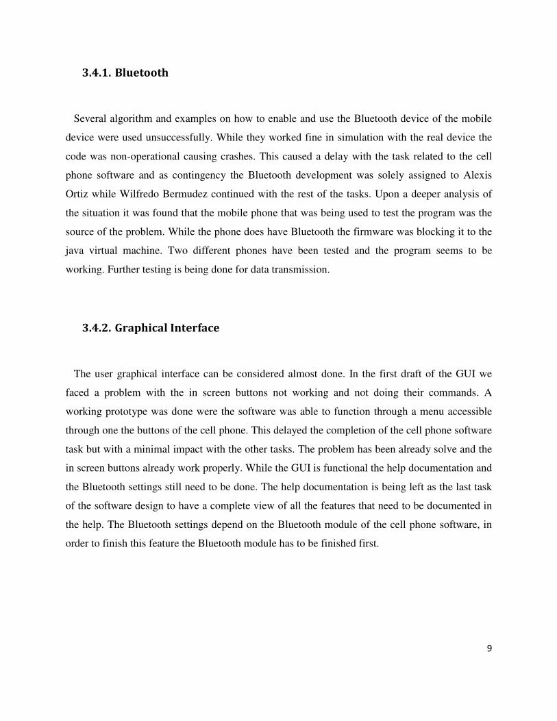
3.4.1. Bluetooth
Several algorithm and examples on how to enable and use the Bluetooth device of the mobile
device were used unsuccessfully. While they worked fine in simulation with the real device the
code was non-operational causing crashes. This caused a delay with the task related to the cell
phone software and as contingency the Bluetooth development was solely assigned to Alexis
Ortiz while Wilfredo Bermudez continued with the rest of the tasks. Upon a deeper analysis of
the situation it was found that the mobile phone that was being used to test the program was the
source of the problem. While the phone does have Bluetooth the firmware was blocking it to the
java virtual machine. Two different phones have been tested and the program seems to be
working. Further testing is being done for data transmission.
3.4.2. Graphical Interface
The user graphical interface can be considered almost done. In the first draft of the GUI we
faced a problem with the in screen buttons not working and not doing their commands. A
working prototype was done were the software was able to function through a menu accessible
through one the buttons of the cell phone. This delayed the completion of the cell phone software
task but with a minimal impact with the other tasks. The problem has been already solve and the
in screen buttons already work properly. While the GUI is functional the help documentation and
the Bluetooth settings still need to be done. The help documentation is being left as the last task
of the software design to have a complete view of all the features that need to be documented in
the help. The Bluetooth settings depend on the Bluetooth module of the cell phone software, in
order to finish this feature the Bluetooth module has to be finished first.
10
3.4.3. Alert Message
When implementing this function we encountered that sending the message directly through
the phones SMS system was not ideal. When the program tries to access the phone's SMS system
the firmware of the phone as a security measure halts the program and asks the user if he wants
to allow access of said feature to the program. In case of emergency the patient might not be in a
position to accept or reject such a prompt. To circumvent this problem the SMS alert system was
implemented using the phones network connection, sending the text message through the
internet.
3.4.4. Communication Protocols & Requesting Data from the
Microcontroller
These tasks depend on the microcontroller and Bluetooth module tasks, due to their delays
these ones had to be delayed. In order to make an efficient communication protocol we need to
know how the data is received from the microcontroller, until the task is done this one is delayed.
Similarly the same happens with requesting data from the microcontroller.
3.5. Corrective Measures
Melvin Rivera was reassigned to help with the analog circuit while the Bluetooth module
arrived. He was also assigned to work with the microcontroller in the initialization, data
sampling, and UART communication process. Alexis Ortiz was assigned to deal with the
Bluetooth in the cell phone. Due to the several delays extra hours will be assigned to the team to
work in the weekends.
11
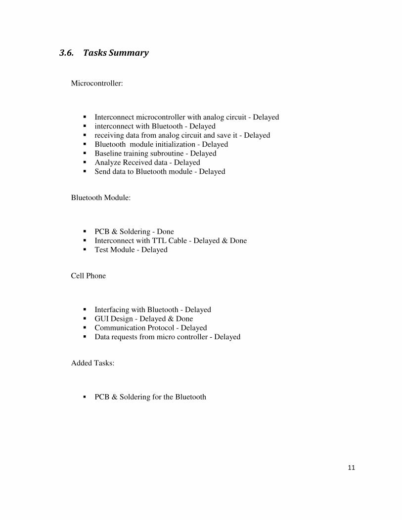
3.6. Tasks Summary
Microcontroller:
� Interconnect microcontroller with analog circuit - Delayed � interconnect with Bluetooth - Delayed � receiving data from analog circuit and save it - Delayed � Bluetooth module initialization - Delayed � Baseline training subroutine - Delayed � Analyze Received data - Delayed � Send data to Bluetooth module - Delayed
Bluetooth Module:
� PCB & Soldering - Done � Interconnect with TTL Cable - Delayed & Done � Test Module - Delayed
Cell Phone
� Interfacing with Bluetooth - Delayed � GUI Design - Delayed & Done � Communication Protocol - Delayed � Data requests from micro controller - Delayed
Added Tasks:
� PCB & Soldering for the Bluetooth
12
4. Budget
This section describes the total actual cost of the project and compares it with the estimated.
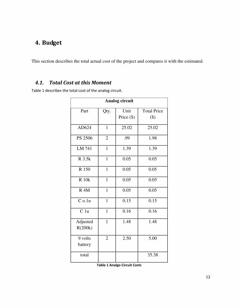
4.1. Total Cost at this Moment
Table 1 describes the total cost of the analog circuit.
Analog circuit
Part Qty. Unit
Price ($)
Total Price
($)
AD624 1 25.02 25.02
PS 2506 2 .99 1.98
LM 741 1 1.39 1.39
R 3.5k 1 0.05 0.05
R 150 1 0.05 0.05
R 10k 1 0.05 0.05
R 4M 1 0.05 0.05
C o.1u 1 0.15 0.15
C 1u 1 0.16 0.16
Adjusted
R(200k)
1 1.48 1.48
9 volts
battery
2 2.50 5.00
total 35.38
Table 1 Analgo Circuit Costs
13
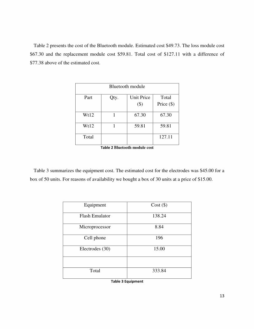
Table 2 presents the cost of the Bluetooth module. Estimated cost $49.73. The loss module cost
$67.30 and the replacement module cost $59.81. Total cost of $127.11 with a difference of
$77.38 above of the estimated cost.
Bluetooth module
Part Qty. Unit Price
($)
Total
Price ($)
Wt12 1 67.30 67.30
Wt12 1 59.81 59.81
Total 127.11
Table 2 Bluetooth module cost
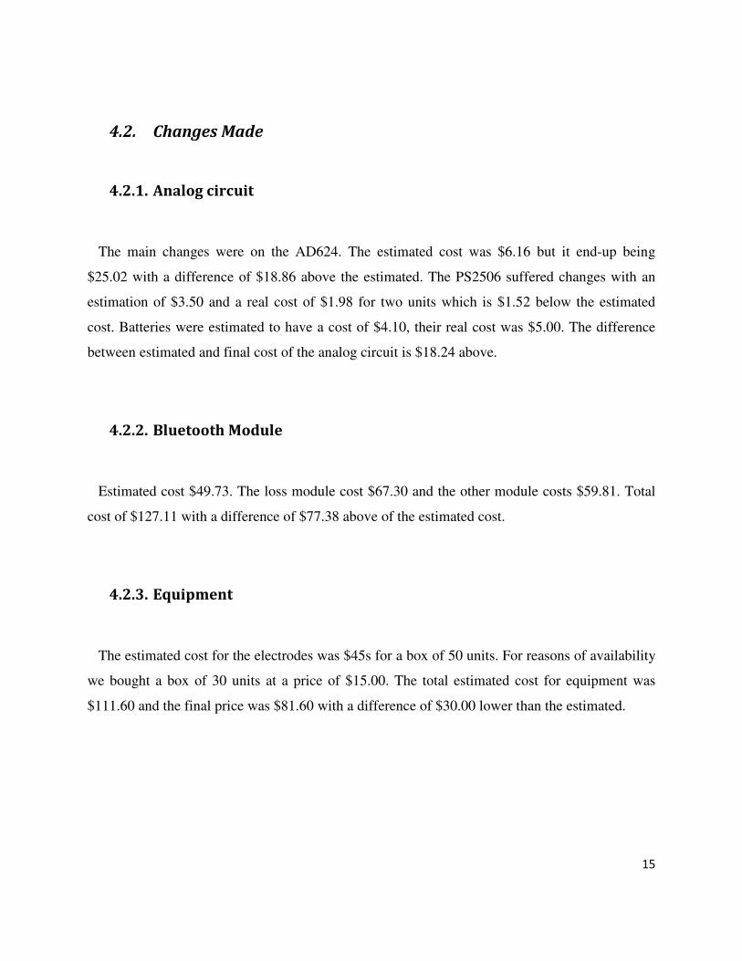
Table 3 summarizes the equipment cost. The estimated cost for the electrodes was $45.00 for a
box of 50 units. For reasons of availability we bought a box of 30 units at a price of $15.00.
Equipment Cost ($)
Flash Emulator 138.24
Microprocessor 8.84
Cell phone 196
Electrodes (30) 15.00
Total 333.84
Table 3 Equipment

14
Table 4 summarizes the total employee cost vs. the estimated cost for that stage.
Name Estimated
hours
Estimated
cost
Worked
hours
Actual
cost
Wilfredo Bermudez 180 3,555 150 2,962.50
Alexis Ortiz 180 3,555 150 2,962.50
Rafael Vega 180 3,450.60 150 2,875.50
Melvin Rivera 180 6,676.20 150 5,563.50
Sub total 17,236.20 14,364.00
Unemployment
Insurance (1.40%)
241.31 201.09
Disability (1.1%)
188.82 158.0
S.S 5.3% 909.74 761.29
Healthcare (7.4%) 1270.21 1062.94
401K/403b (4.3%)
738.09 617.65
Consultant 10 1000 6 600.00
Total 21,513.1 17,765
Table 4 Employees
15
4.2. Changes Made
4.2.1. Analog circuit
The main changes were on the AD624. The estimated cost was $6.16 but it end-up being
$25.02 with a difference of $18.86 above the estimated. The PS2506 suffered changes with an
estimation of $3.50 and a real cost of $1.98 for two units which is $1.52 below the estimated
cost. Batteries were estimated to have a cost of $4.10, their real cost was $5.00. The difference
between estimated and final cost of the analog circuit is $18.24 above.
4.2.2. Bluetooth Module
Estimated cost $49.73. The loss module cost $67.30 and the other module costs $59.81. Total
cost of $127.11 with a difference of $77.38 above of the estimated cost.
4.2.3. Equipment
The estimated cost for the electrodes was $45s for a box of 50 units. For reasons of availability
we bought a box of 30 units at a price of $15.00. The total estimated cost for equipment was
$111.60 and the final price was $81.60 with a difference of $30.00 lower than the estimated.
16
4.2.4. Employee Cost:
Estimated cost of employees to date was $21,513 and the actual cost is $17,765 with a
difference of $3,718 below the estimated. The difference between the estimated and actual cost is
due to the following:
• It was estimated a total of 28 hours of work per week. This estimate was too high
considering that each member has other courses that also require time. For that
reason, we reduced the number of hours per week to about 18 hours in the first 5
weeks. For the next 2 weeks we are working weekends to complete the 28 hours a
week
• Estimated hours of professional consulting services was 10 hours. So far only 6
hours of consulting have been used. The difference between the estimated and the
total cost is $400 below the estimated.
4.3. Project Summary
The total estimated cost for the project at this stage was $21,968.10 and so far the cost is
$18,102.70. The difference is $3866.32 below the estimated.
17
5. Technical Plan
In the following section we intent to present progress in a more technical sense with respect to
the overall project.
5.1. Analog Circuit
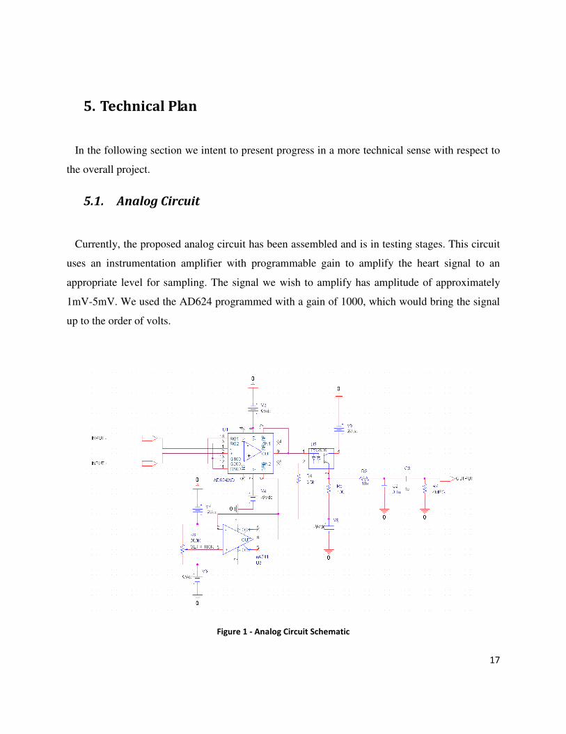
Currently, the proposed analog circuit has been assembled and is in testing stages. This circuit
uses an instrumentation amplifier with programmable gain to amplify the heart signal to an
appropriate level for sampling. The signal we wish to amplify has amplitude of approximately
1mV-5mV. We used the AD624 programmed with a gain of 1000, which would bring the signal
up to the order of volts.
Figure 1 - Analog Circuit Schematic
18
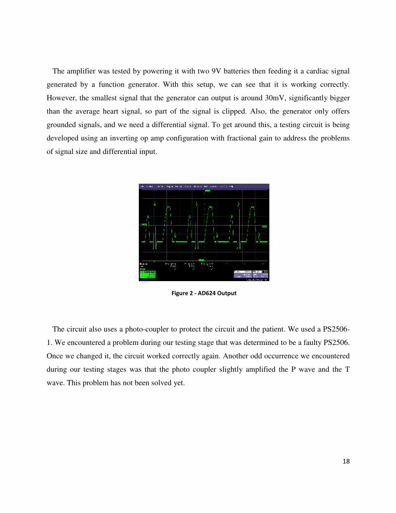
The amplifier was tested by powering it with two 9V batteries then feeding it a cardiac signal
generated by a function generator. With this setup, we can see that it is working correctly.
However, the smallest signal that the generator can output is around 30mV, significantly bigger
than the average heart signal, so part of the signal is clipped. Also, the generator only offers
grounded signals, and we need a differential signal. To get around this, a testing circuit is being
developed using an inverting op amp configuration with fractional gain to address the problems
of signal size and differential input.
Figure 2 - AD624 Output
The circuit also uses a photo-coupler to protect the circuit and the patient. We used a PS2506-
1. We encountered a problem during our testing stage that was determined to be a faulty PS2506.
Once we changed it, the circuit worked correctly again. Another odd occurrence we encountered
during our testing stages was that the photo coupler slightly amplified the P wave and the T
wave. This problem has not been solved yet.
19
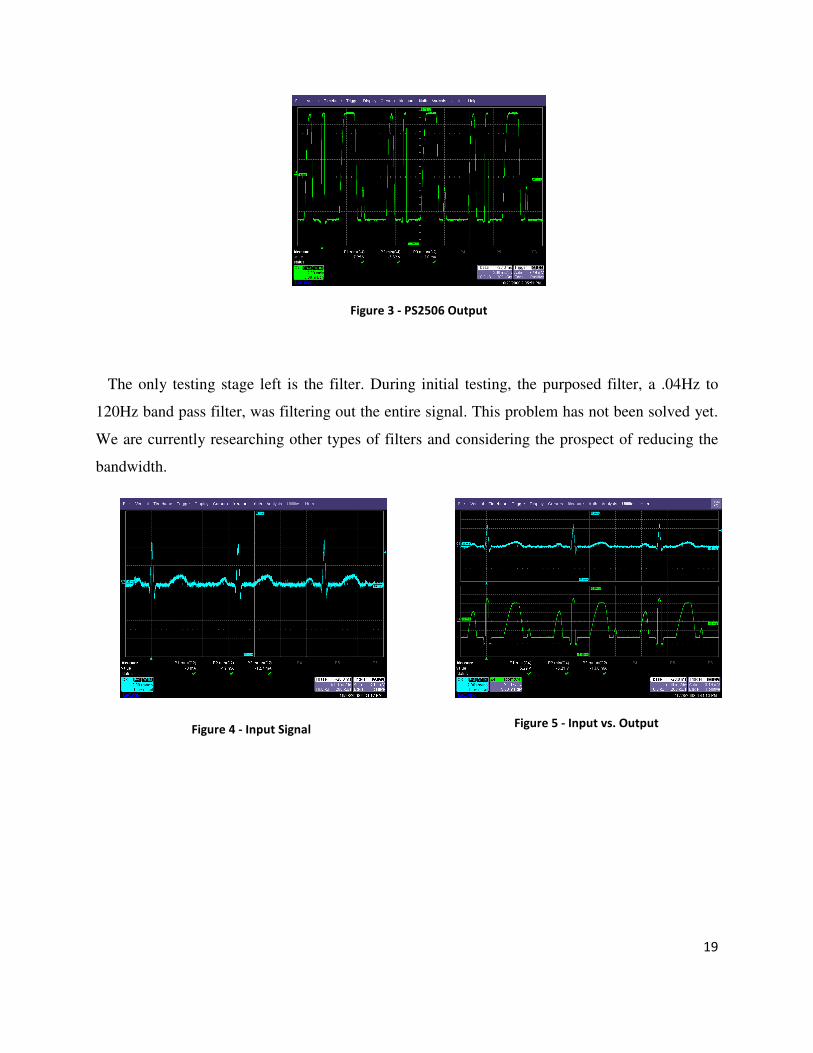
Figure 3 - PS2506 Output
The only testing stage left is the filter. During initial testing, the purposed filter, a .04Hz to
120Hz band pass filter, was filtering out the entire signal. This problem has not been solved yet.
We are currently researching other types of filters and considering the prospect of reducing the
bandwidth.
Figure 4 - Input Signal
Figure 5 - Input vs. Output
20
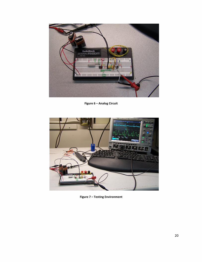
Figure 6 – Analog Circuit
Figure 7 – Testing Environment
21
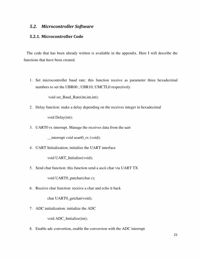
5.2. Microcontroller Software
5.2.1. Microcontroller Code
The code that has been already written is available in the appendix. Here I will describe the
functions that have been created.
1. Set microcontroller baud rate: this function receive as parameter three hexadecimal
numbers to set the UBR00 ; UBR10; UMCTL0 respectively
void set_Baud_Rate(int,int,int);
2. Delay function: make a delay depending on the receives integer in hexadecimal
void Delay(int);
3. UART0 rx interrupt. Manage the receives data from the uart
__interrupt void usart0_rx (void);
4. UART Initialization; initialize the UART interface
void UART_Initialize(void);
5. Send char function: this function send a ascii char via UART TX
void UART0_putchar(char c);
6. Receive char function: receive a char and echo it back
char UART0_getchar(void);
7. ADC initialization: initialize the ADC
void ADC_Initialize(int);
8. Enable adc convertion, enable the conversion with the ADC interrupt
22
void convert_ADC_Enable(void);
9. Disable ADC convertion, disable the ADC conversion interrupt
void convert_ADC_Disable(void);
10. Set ports Set the ports to the input or output mode
void Set_Ports(void);
11. Request info from Bluetooth module send info command to the Bluetooth module
void request_INFO(void);
12. Change baud rate of the Bluetooth module
void set_Baud_Rate_19200(void);
5.2.2. Functions that will be Created
1- Initialize Bluetooth module
2- Connect to cell via Bluetooth
3- Send alert message to cell phone
4- Send ECG data to cell phone
5- Analyze received data
23
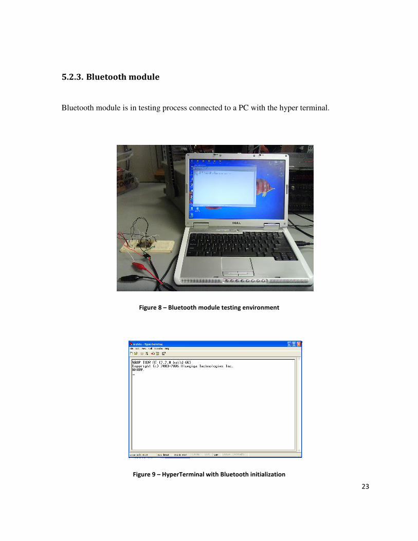
5.2.3. Bluetooth module
Bluetooth module is in testing process connected to a PC with the hyper terminal.
Figure 8 – Bluetooth module testing environment
Figure 9 – HyperTerminal with Bluetooth initialization
24
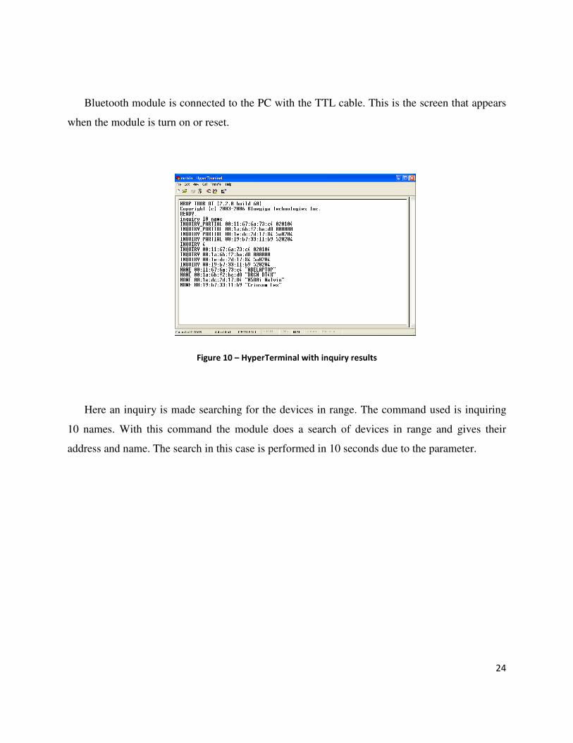
Bluetooth module is connected to the PC with the TTL cable. This is the screen that appears
when the module is turn on or reset.
Figure 10 – HyperTerminal with inquiry results
Here an inquiry is made searching for the devices in range. The command used is inquiring
10 names. With this command the module does a search of devices in range and gives their
address and name. The search in this case is performed in 10 seconds due to the parameter.
25
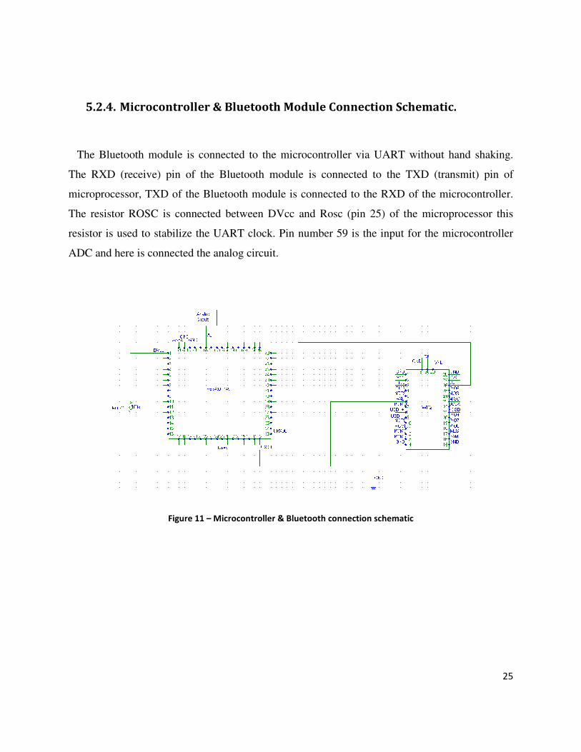
5.2.4. Microcontroller & Bluetooth Module Connection Schematic.
The Bluetooth module is connected to the microcontroller via UART without hand shaking.
The RXD (receive) pin of the Bluetooth module is connected to the TXD (transmit) pin of
microprocessor, TXD of the Bluetooth module is connected to the RXD of the microcontroller.
The resistor ROSC is connected between DVcc and Rosc (pin 25) of the microprocessor this
resistor is used to stabilize the UART clock. Pin number 59 is the input for the microcontroller
ADC and here is connected the analog circuit.
Figure 11 – Microcontroller & Bluetooth connection schematic
26
5.3. Cell Phone Device
5.3.1. Connecting to Bluetooth via Cell Phone
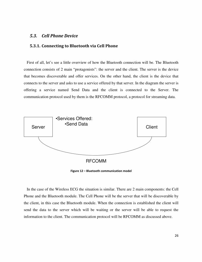
First of all, let’s see a little overview of how the Bluetooth connection will be. The Bluetooth
connection consists of 2 main “protagonists”: the server and the client. The server is the device
that becomes discoverable and offer services. On the other hand, the client is the device that
connects to the server and asks to use a service offered by that server. In the diagram the server is
offering a service named Send Data and the client is connected to the Server. The
communication protocol used by them is the RFCOMM protocol, a protocol for streaming data.
Server Client
RFCOMM
•Services Offered:
•Send Data
Figure 12 – Bluetooth communication model
In the case of the Wireless ECG the situation is similar. There are 2 main components: the Cell
Phone and the Bluetooth module. The Cell Phone will be the server that will be discoverable by
the client, in this case the Bluetooth module. When the connection is established the client will
send the data to the server which will be waiting or the server will be able to request the
information to the client. The communication protocol will be RFCOMM as discussed above.
27
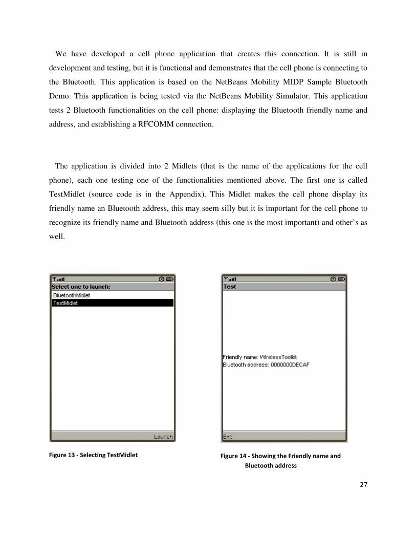
We have developed a cell phone application that creates this connection. It is still in
development and testing, but it is functional and demonstrates that the cell phone is connecting to
the Bluetooth. This application is based on the NetBeans Mobility MIDP Sample Bluetooth
Demo. This application is being tested via the NetBeans Mobility Simulator. This application
tests 2 Bluetooth functionalities on the cell phone: displaying the Bluetooth friendly name and
address, and establishing a RFCOMM connection.
The application is divided into 2 Midlets (that is the name of the applications for the cell
phone), each one testing one of the functionalities mentioned above. The first one is called
TestMidlet (source code is in the Appendix). This Midlet makes the cell phone display its
friendly name an Bluetooth address, this may seem silly but it is important for the cell phone to
recognize its friendly name and Bluetooth address (this one is the most important) and other’s as
well.
Figure 13 - Selecting TestMidlet
Figure 14 - Showing the Friendly name and
Bluetooth address
28
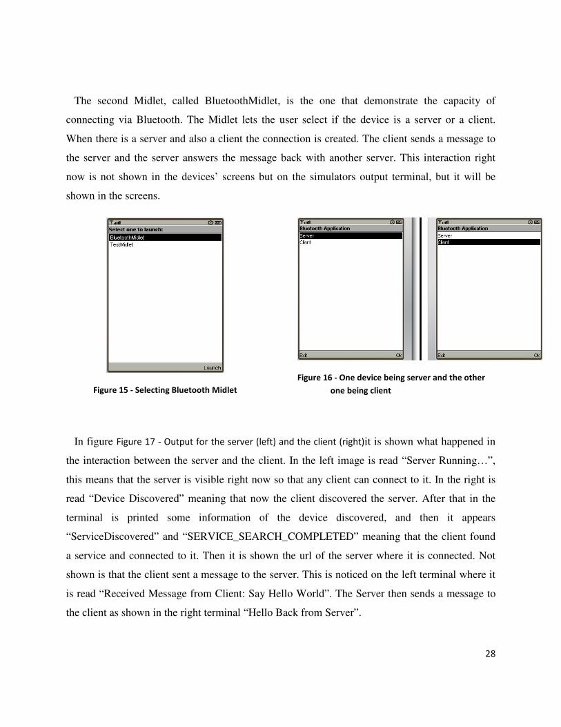
The second Midlet, called BluetoothMidlet, is the one that demonstrate the capacity of
connecting via Bluetooth. The Midlet lets the user select if the device is a server or a client.
When there is a server and also a client the connection is created. The client sends a message to
the server and the server answers the message back with another server. This interaction right
now is not shown in the devices’ screens but on the simulators output terminal, but it will be
shown in the screens.
Figure 15 - Selecting Bluetooth Midlet
Figure 16 - One device being server and the other
one being client
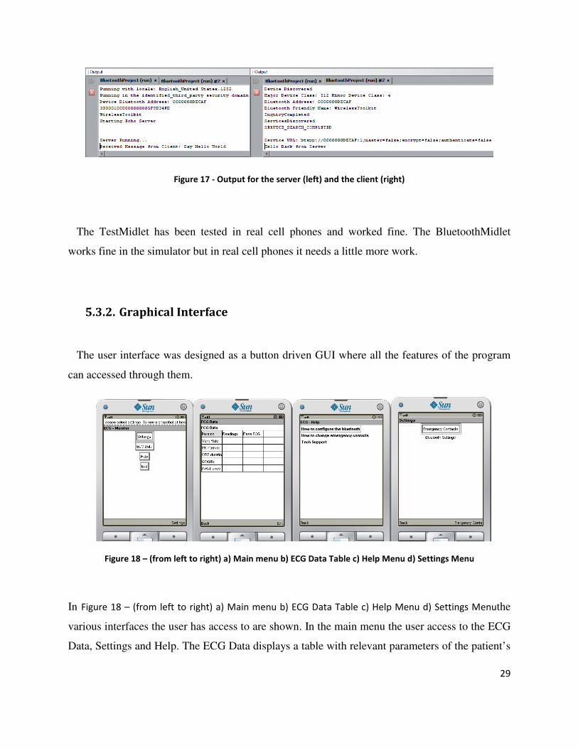
In figure Figure 17 - Output for the server (left) and the client (right)it is shown what happened in
the interaction between the server and the client. In the left image is read “Server Running…”,
this means that the server is visible right now so that any client can connect to it. In the right is
read “Device Discovered” meaning that now the client discovered the server. After that in the
terminal is printed some information of the device discovered, and then it appears
“ServiceDiscovered” and “SERVICE_SEARCH_COMPLETED” meaning that the client found
a service and connected to it. Then it is shown the url of the server where it is connected. Not
shown is that the client sent a message to the server. This is noticed on the left terminal where it
is read “Received Message from Client: Say Hello World”. The Server then sends a message to
the client as shown in the right terminal “Hello Back from Server”.
29
Figure 17 - Output for the server (left) and the client (right)
The TestMidlet has been tested in real cell phones and worked fine. The BluetoothMidlet
works fine in the simulator but in real cell phones it needs a little more work.
5.3.2. Graphical Interface
The user interface was designed as a button driven GUI where all the features of the program
can accessed through them.
Figure 18 – (from left to right) a) Main menu b) ECG Data Table c) Help Menu d) Settings Menu
In Figure 18 – (from left to right) a) Main menu b) ECG Data Table c) Help Menu d) Settings Menuthe
various interfaces the user has access to are shown. In the main menu the user access to the ECG
Data, Settings and Help. The ECG Data displays a table with relevant parameters of the patient’s
30
heart. In a same manner the in the help menu the user can access documentation with relevant
information of the ECG Monitor system.
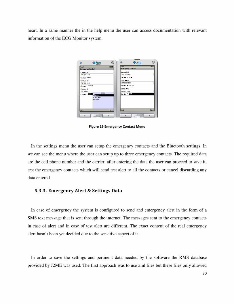
Figure 19 Emergency Contact Menu
In the settings menu the user can setup the emergency contacts and the Bluetooth settings. In
we can see the menu where the user can setup up to three emergency contacts. The required data
are the cell phone number and the carrier, after entering the data the user can proceed to save it,
test the emergency contacts which will send test alert to all the contacts or cancel discarding any
data entered.
5.3.3. Emergency Alert & Settings Data
In case of emergency the system is configured to send and emergency alert in the form of a
SMS text message that is sent through the internet. The messages sent to the emergency contacts
in case of alert and in case of test alert are different. The exact content of the real emergency
alert hasn’t been yet decided due to the sensitive aspect of it.
In order to save the settings and pertinent data needed by the software the RMS database
provided by J2ME was used. The first approach was to use xml files but these files only allowed
31
to read data and not to write data to the xml file. Settings that are going to be saved in this
database are SMS configuration for each carrier, emergency contacts number and carrier, and the
Bluetooth settings.
6. Future Works
• Data Sampling - Receive data from analog circuit and save it
• Bluetooth module initialization
• Baseline training subroutine – Train the microprocessor with the baseline signal
• Analyze data – interpret data received from analog circuit
• Send data from microprocessor to Bluetooth module
• Test Bluetooth module
• Interface cell phone with Bluetooth
• Communication protocols – Design communication protocols between cell phone and
Bluetooth.
• Data request from microcontroller simulated with PC – Display data received from PC
(simulates microprocessor)
32
Bibliographic References
Webster, J. John Wiley& Sons. (2002). Medical Instrumentation Application and Design (3rd
ed.). Asia : Pte. Ltd.
33
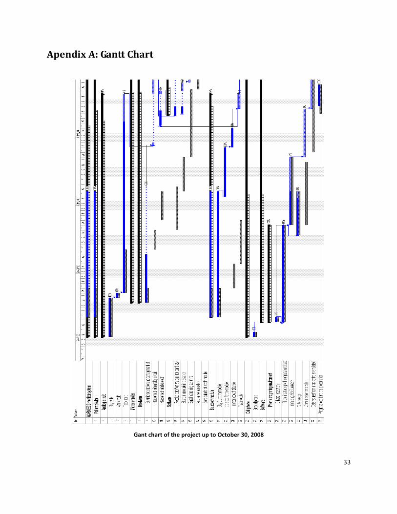
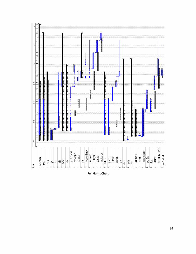
Apendix A: Gantt Chart
Gant chart of the project up to October 30, 2008
34
Full Gantt Chart
35
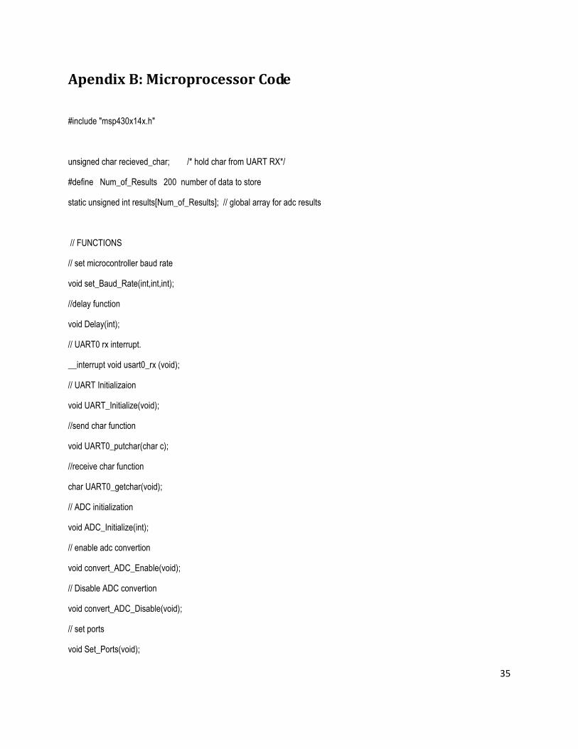
Apendix B: Microprocessor Code
#include "msp430x14x.h"
unsigned char recieved_char; /* hold char from UART RX*/
#define Num_of_Results 200 number of data to store
static unsigned int results[Num_of_Results]; // global array for adc results
// FUNCTIONS
// set microcontroller baud rate
void set_Baud_Rate(int,int,int);
//delay function
void Delay(int);
// UART0 rx interrupt.
__interrupt void usart0_rx (void);
// UART Initializaion
void UART_Initialize(void);
//send char function
void UART0_putchar(char c);
//receive char function
char UART0_getchar(void);
// ADC initialization
void ADC_Initialize(int);
// enable adc convertion
void convert_ADC_Enable(void);
// Disable ADC convertion
void convert_ADC_Disable(void);
// set ports
void Set_Ports(void);
36
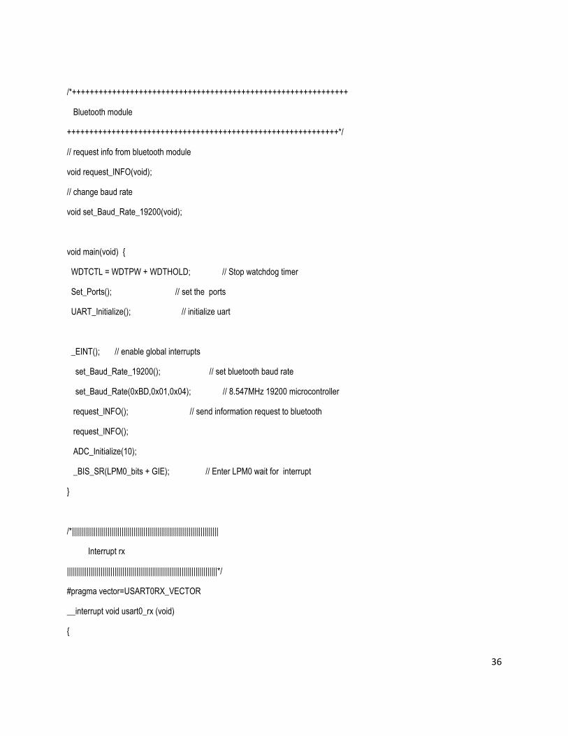
/*++++++++++++++++++++++++++++++++++++++++++++++++++++++++++++++
Bluetooth module
+++++++++++++++++++++++++++++++++++++++++++++++++++++++++++++*/
// request info from bluetooth module
void request_INFO(void);
// change baud rate
void set_Baud_Rate_19200(void);
void main(void) {
WDTCTL = WDTPW + WDTHOLD; // Stop watchdog timer
Set_Ports(); // set the ports
UART_Initialize(); // initialize uart
_EINT(); // enable global interrupts
set_Baud_Rate_19200(); // set bluetooth baud rate
set_Baud_Rate(0xBD,0x01,0x04); // 8.547MHz 19200 microcontroller
request_INFO(); // send information request to bluetooth
request_INFO();
ADC_Initialize(10);
_BIS_SR(LPM0_bits + GIE); // Enter LPM0 wait for interrupt
}
/*||||||||||||||||||||||||||||||||||||||||||||||||||||||||||||||||||||||||||
Interrupt rx
||||||||||||||||||||||||||||||||||||||||||||||||||||||||||||||||||||||||||||*/
#pragma vector=USART0RX_VECTOR
__interrupt void usart0_rx (void)
{
37
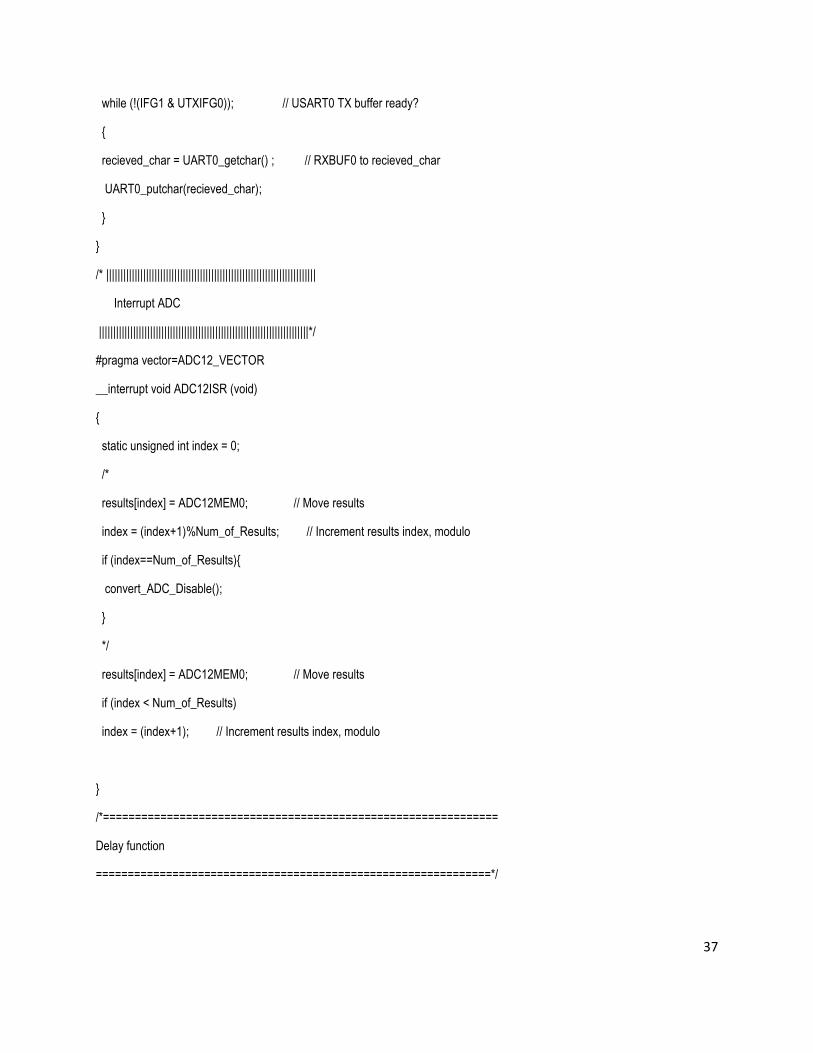
while (!(IFG1 & UTXIFG0)); // USART0 TX buffer ready?
{
recieved_char = UART0_getchar() ; // RXBUF0 to recieved_char
UART0_putchar(recieved_char);
}
}
/* ||||||||||||||||||||||||||||||||||||||||||||||||||||||||||||||||||||||||||
Interrupt ADC
||||||||||||||||||||||||||||||||||||||||||||||||||||||||||||||||||||||||||*/
#pragma vector=ADC12_VECTOR
__interrupt void ADC12ISR (void)
{
static unsigned int index = 0;
/*
results[index] = ADC12MEM0; // Move results
index = (index+1)%Num_of_Results; // Increment results index, modulo
if (index==Num_of_Results){
convert_ADC_Disable();
}
*/
results[index] = ADC12MEM0; // Move results
if (index < Num_of_Results)
index = (index+1); // Increment results index, modulo
}
/*==============================================================
Delay function
==============================================================*/
38
void Delay(int time) // time in hexadecimal
{
volatile unsigned int delay_count = time;
for(;delay_count!=0;delay_count--);
}
/* ==============================================================
set the ports nedded
==============================================================*/
void Set_Ports(void){
P3DIR |= 0xff; // set all pins as output
//P2DIR |= 0xff; //set all pins as out
//P5DIR |= 0xff; // set all pins as output
P3SEL |= 0x30; // bits 4-5 are for special function UART0
P2SEL = 0x60; // bit 5-6 for special function ROSC, ADC12CLK
P5SEL |= 0x30; //output mclk & smclk
P6SEL |= 0x01; // bit 0 port 6 for analog imput ADC
}
/*==============================================================
ADC Initialization
==============================================================*/
void ADC_Initialize(int count)
{
P6SEL |= 0x01; // bit 0 port 6 for analog imput ADC
_BIS_SR(SREF1); // enable internal references
_BIC_SR(SREF0 + SREF2); // 2.5 V+ and 0 V-
39
ADC12CTL0 = REFON + REF2_5V; // enable internal reference 2.5V
ADC12CTL0 = ADC12ON + SHT0_10+MSC; // Turn on ADC12, set sampling time, start . with SHI riding esdge signal and then . . continue taking samples
ADC12CTL1 = ADC12SSEL_3 + SHS_0; // set internal SMCLK clock . source
ADC12CTL1 = SHP+CONSEQ_2; // Use sampling timer to take samples, set . mode to repest single channel (0x10)
ADC12IE = 0x01; // Enable ADC12IFG.0
ADC12CTL0 |= ENC; // enable conversion
ADC12CTL0 |= ADC12SC; // Start conversion
_BIS_SR(LPM0_bits + GIE); // Enter LPM0,Enable interrupts
// para prueba
/**ADC12CTL0 = ADC12ON+SHT0_8+MSC; // Turn on ADC12, set sampling time
ADC12CTL1 = SHP+CONSEQ_2; // Use sampling timer, set mode
ADC12IE = 0x01; // Enable ADC12IFG.0
ADC12CTL0 |= ENC; // Enable conversions
ADC12CTL0 |= ADC12SC; // Start conversion
_BIS_SR(LPM0_bits + GIE); // Enter LPM0,Enable interrupts
*/
}
/*==============================================================
enable conversion
==============================================================*/
void convert_ADC_Enable(void)
{
_BIS_SR (ENC); //activate adc
_BIS_SR (ADC12ON);
// enable convertion
}
40
/*=============================================================
disable convertion
==============================================================*/
void convert_ADC_Disable(void){
_BIC_SR (ENC);
}
/*==============================================================
UART0 Initialization
/==============================================================*/
void UART_Initialize(void)
{
/* the minimun baud rate to wt12 is 19200 baud rate*/
// UART0 - 19200 bps
// for 8MHZ clock rate
//P3DIR |= 0xff;
// P3SEL |= 0x38; // bits 4-5 are for special function UART0
// P2SEL |= 0x20; // bit 5 for special function
//P2DIR |= 0x20;
// P5SEL |= 0x30; //output mclk & smclk
//P5DIR |= 0xff; // set all pins as output
BCSCTL2 |= DCOR; // Rosc
_BIS_SR(OSCOFF); // XTAL not used
ME1 |= UTXE0 + URXE0; // Enabled USART0 TXD/RXD
UCTL0 |= CHAR; // 8-bit character
UTCTL0 |= SSEL1; // UCLK = SMCLKset_Baud_Rate(0x4A, 0x00, . . . . 0x84);
// 8.547MHz 115200, UBR00=0x4A; UBR10=0x00; . UMCTL0=0x84
UCTL0 &= ~SWRST; // Initialize USART state machine
41
IE1 |= URXIE0; // Enable USART0 RX interrupt
}
/*==============================================================
set baud rate
==============================================================*/
void set_Baud_Rate(int ubr00, int ubr10, int umctl0)
{
_BIC_SR(GIE); // disable all interrups
UBR00 = ubr00;
UBR10 = ubr10;
UMCTL0 = umctl0;
Delay(0xff8);
_BIS_SR(GIE); // Enabled all interrupts
}
/*=============================================================
send a char via UART0
==============================================================*/
void UART0_putchar(char c)
{
// wait for other character to transmit
while (!(IFG1 & UTXIFG0));
U0TXBUF = c;
}
/* ==============================================================
recieve a char via UART0
==============================================================*/
char UART0_getchar(void)
{
for (;;)
42
{
// if (U0RCTL & RXERR)
// {
// if you want to answer receive errors, do it here.
// U0RCTL &= ~(FE+PE+OE+BRK+RXERR);
// }
// else
// {
// if (IFG1 & URXIFG0)
// { // we've received a character
return U0RXBUF;
}
}
//}
//}
/*============================================================
INFO displays information about iWRAP version and features.
=============================================================*/
void request_INFO(void)
{
UART0_putchar('I');
UART0_putchar('N');
UART0_putchar('F');
UART0_putchar('O');
}
/* ==============================================================
wt12 control functions set baud rate 19200
=============================================================*/
43
// set baud rate 19200, 8 bit no parity, one stop bit bluetooth module
void set_Baud_Rate_19200(void)
{
UART0_putchar('S');
UART0_putchar('E');
UART0_putchar('T');
UART0_putchar(' ');
UART0_putchar('C');
UART0_putchar('O');
UART0_putchar('N');
UART0_putchar('T');
UART0_putchar('R');
UART0_putchar('O');
UART0_putchar('L');
UART0_putchar(' ');
UART0_putchar('B');
UART0_putchar('A');
UART0_putchar('U');
UART0_putchar('D');
UART0_putchar(' ');
UART0_putchar('1');
UART0_putchar('9');
UART0_putchar('2');
UART0_putchar('0');
UART0_putchar('0');
UART0_putchar('N');
UART0_putchar(',');
UART0_putchar('8');
UART0_putchar('N');

44
UART0_putchar('1');
}
45
Appendix V
//BluetoothMidlet.java
package capstone;
import java.io.IOException;
import java.io.InputStream;
import javax.bluetooth.UUID;
import javax.microedition.io.StreamConnection;
import javax.microedition.lcdui.Command;
import javax.microedition.lcdui.CommandListener;
import javax.microedition.lcdui.Display;
import javax.microedition.lcdui.Displayable;
import javax.microedition.lcdui.List;
import javax.microedition.midlet.MIDlet;
/**This Midlet is in charge of selecting if the device will be
* server or client
*/
public final class BluetoothMidlet extends MIDlet implements CommandListener {
// Shared UUID by server and client, RFCOMM UUID
public static final UUID RFCOMM_UUID = new UUID(0x0003);
/** The messages are shown this amount of time. */
static final int ALERT_TIMEOUT = 2000;
/** A list of menu items */
private static final String[] elements = { "Server", "Client" };
/** Soft button for exiting the demo. */
private final Command EXIT_CMD = new Command("Exit", Command.EXIT, 2);
46
/** Soft button for launching a client or sever. */
private final Command OK_CMD = new Command("Ok", Command.SCREEN, 1);
/** A menu list instance */
private final List menu = new List("Bluetooth Application", List.IMPLICIT, elements, null);
/** A GUI part of server*/
private GUIServer server;
/** A GUI part of client*/
private GUIClient client;
/** value is true after creating the server/client */
private boolean isInit = false;
/**
* Constructs main screen of the MIDlet.
*/
public BluetoothMidlet() {
menu.addCommand(EXIT_CMD);
menu.addCommand(OK_CMD);
menu.setCommandListener(this);
System.out.println(RFCOMM_UUID.toString()); //debug purposes
}
/**
* Creates the demo view and action buttons.
*/
public void startApp() {
if (!isInit) {
show();
} }
/**
* Destroys the application.

47
*/
protected void destroyApp(boolean unconditional) {
if (server != null) {
server.destroy();
}
if (client != null) {
client.destroy();
} }
/**
* Does nothing. Redefinition is required by MIDlet class.
*/
protected void pauseApp() {
}
/**
* Responds to commands issued on "client or server" form.
*
* @param c command object source of action
* @param d screen object containing the item action was performed on
*/
public void commandAction(Command c, Displayable d) {
if (c == EXIT_CMD) {
destroyApp(true);
notifyDestroyed();
return;
}
switch (menu.getSelectedIndex()) {
case 0:
server = new GUIServer(this);
break;
48
case 1:
client = new GUIClient(this);
break;
default:
System.err.println("Unexpected choice...");
break;
}
isInit = true;
}
/** Shows main menu of MIDlet on the screen. */
void show() {
Display.getDisplay(this).setCurrent(menu);
}
/**
* Returns the displayable object of this screen -
* it is required for Alert construction for the error
* cases.
*/
Displayable getDisplayable() {
return menu;
}
/**
* Reads data from the connection and returns it as a
* String.
*/
public final static String readData(StreamConnection conn) {
InputStream input = null;
byte[] data = null;
49
try {
input = conn.openInputStream();
// Probably want to throw an exception if length is not greater then 0
int length = input.read();
data= new byte[length];
length = 0;
// Assemble data
while (length != data.length) {
int ch = input.read(data, length, data.length - length);
if (ch == -1) {
throw new IOException("Can't read data");
}
length += ch;
}
} catch (IOException e) {
System.err.println(e);
} finally {
// close input stream
if (input != null) {
try {
input.close();
} catch (IOException e) {
} } }
return new String(data);
} }
//GuiServer.java
package capstone;
import javax.microedition.lcdui.Command;
50
import javax.microedition.lcdui.CommandListener;
import javax.microedition.lcdui.Displayable;
/**This class will hold the GUI of the server*/
final class GUIServer implements CommandListener {
/** Keeps the parent MIDlet reference to process specific actions. */
private BluetoothMidlet parent;
/** This object handles the real transmission. */
private BluetoothServer bt_server;
/** Constructs server GUI. */
GUIServer(BluetoothMidlet parent) {
this.parent = parent;
bt_server = new BluetoothServer();//this);
}
/**
* Process the command event.
*
* @param c - the issued command.
* @param d - the screen object the command was issued for.
*/
public void commandAction(Command c, Displayable d) {
}
/**
* We have to provide this method due to "do not do network
* operation in command listener method" restriction, which
* is caused by crooked midp design.
*
51
* This method is called by BTImageServer after it is done
* with bluetooth initialization and next screen is ready
* to appear.
*/
void completeInitialization(boolean isBTReady) {
}
/** Destroys this component. */
void destroy() {
}
}
//GuiClient.java
package capstone;
import javax.microedition.lcdui.Command;
import javax.microedition.lcdui.CommandListener;
import javax.microedition.lcdui.Displayable;
/**This class will hold the GUI of the client*/
final class GUIClient implements CommandListener {
/** Keeps the parent MIDlet reference to process specific actions. */
private BluetoothMidlet parent;
/** This object handles the real transmission. */
private BluetoothClient bt_client;
/** Constructs client GUI. */
GUIClient(BluetoothMidlet parent) {
this.parent = parent;
bt_client = new BluetoothClient();//(this);
}
/**
* Process the command events.
52
*
* @param c - the issued command.
* @param d - the screen object the command was issued for.
*/
public void commandAction(Command c, Displayable d) {
}
/**
* We have to provide this method due to "do not do network
* operation in command listener method" restriction, which
* is caused by crooked midp design.
*
* This method is called by BTImageClient after it is done
* with bluetooth initialization and next screen is ready
* to appear.
*/
void completeInitialization(boolean isBTReady) {
}
/** Destroys this component. */
void destroy() {
}}
//BluetoothServer.java
package capstone;
import javax.bluetooth.*;
import javax.microedition.io.*;
import java.io.*;
/**Class that represents a Bluetooth Server*/
public class BluetoothServer implements Runnable {
53
StreamConnectionNotifier notifier;
StreamConnection conn;
LocalDevice localDevice;
ServiceRecord serviceRecord;
InputStream input;
OutputStream output;
private boolean isInit;
private static String serverUrl = "btspp://localhost:" + BluetoothMidlet.RFCOMM_UUID + ";name=rfcommtest;authorize=false";
/**
* Default constructor.
*/
public BluetoothServer() {
isInit = false;
Thread thread = new Thread(this);
thread.start();
}
public void run() {
if (!isInit) {
// Initialization is done in the thread to avoid dead lock 'isInit' ensures it is done once only
try {
conn = null;
localDevice = LocalDevice.getLocalDevice();
System.out.println(localDevice.getFriendlyName());//Testing purposes
localDevice.setDiscoverable( DiscoveryAgent.GIAC );
notifier = (StreamConnectionNotifier)Connector.open(serverUrl);
} catch (BluetoothStateException e) {
System.err.println( "BluetoothStateException: " + e.getMessage() );
} catch (IOException e) {
System.err.println( "IOException: " + e.getMessage() );
54
}
isInit=true;
System.out.println( "Starting Echo Server" );
}
//
try {
System.out.println("\n\nServer Running...");
// Pauses thread until Transmission occurs
conn = notifier.acceptAndOpen();
// Read Data Transmission
String msg = BluetoothMidlet.readData(conn);
System.out.println("Received Message from Client: " + msg);
// Send Back a Message
msg = "Hello Back from Server";
output = conn.openOutputStream();
output.write(msg.length()); // length is 1 byte
output.write(msg.getBytes());
output.close();
} catch (Exception ex) {
System.err.println("Bluetooth Server Running Error: " + ex);
} }}
//BluetoothClient.java
package capstone;
import javax.bluetooth.*;
import javax.microedition.io.*;
import java.io.*;
/**
55
* Class that represents a Bluetooth Client
*
*/
class BluetoothClient implements DiscoveryListener {
private DiscoveryAgent discoveryAgent;
private RemoteDevice[] remoteDevices;
private UUID[] uuidSet;
private String serviceUrl;
/**
* Default constructor.
*/
public BluetoothClient() {
try {
LocalDevice localDevice = LocalDevice.getLocalDevice();
discoveryAgent = localDevice.getDiscoveryAgent();
discoveryAgent.startInquiry(DiscoveryAgent.GIAC, this);
} catch (Exception e) {
System.out.println(e);
} }
/**
* Method called when a device is discovered
* @param btDevice
* @param cod
*/
public void deviceDiscovered(RemoteDevice btDevice, DeviceClass cod) {
try {
// Get Device Info
System.out.println("Device Discovered");
System.out.println("Major Device Class: " + cod.getMajorDeviceClass() + " Minor Device Class: " + cod.getMinorDeviceClass());
56
System.out.println("Bluetooth Address: " + btDevice.getBluetoothAddress());
System.out.println("Bluetooth Friendly Name: " + btDevice.getFriendlyName(true));
// Search for Services
uuidSet = new UUID[1];
uuidSet[0] = BluetoothMidlet.RFCOMM_UUID;
int searchID = discoveryAgent.searchServices(null,uuidSet,btDevice,this);
} catch (Exception e) {
System.out.println("Device Discovered Error: " + e);
} }
/**
* Method called when the inquiry is completed
* @param discType
*/
public void inquiryCompleted(int discType) {
System.out.println("InquiryCompleted");
}
/**
* Method called when a service is discovered
* @param transID
* @param servRecord
*/
public void servicesDiscovered(int transID, ServiceRecord[] servRecord) {
System.out.println("ServicesDiscovered");
// in this example there is only one service
for(int i=0;i<servRecord.length;i++) {
serviceUrl = servRecord[i].getConnectionURL(0,false);
} }
/**
57
* Method that is called when the service search is completed
* @param transID
* @param responseCode
*/
public void serviceSearchCompleted(int transID, int responseCode) {
if(responseCode == SERVICE_SEARCH_ERROR)
System.out.println("SERVICE_SEARCH_ERROR\n");
if(responseCode == SERVICE_SEARCH_COMPLETED) {
System.out.println("SERVICE_SEARCH_COMPLETED\n");
System.out.println("Service URL: " + serviceUrl);
StreamConnection conn = null;
try {
String msg = "Say Hello World";
conn = (StreamConnection)Connector.open(serviceUrl);
OutputStream output = conn.openOutputStream();
output.write(msg.length());
output.write(msg.getBytes());
output.close();
System.out.println(BluetoothMidlet.readData(conn));
} catch (Exception ex) {
System.out.println(ex);
} finally {
try {
conn.close();
} catch (IOException ioe) {
System.out.println("Error Closing connection " + ioe);
} } }
if(responseCode == SERVICE_SEARCH_TERMINATED)
System.out.println("SERVICE_SEARCH_TERMINATED\n");
58
if(responseCode == SERVICE_SEARCH_NO_RECORDS)
System.out.println("SERVICE_SEARCH_NO_RECORDS\n");
if(responseCode == SERVICE_SEARCH_DEVICE_NOT_REACHABLE)
System.out.println("SERVICE_SEARCH_DEVICE_NOT_REACHABLE\n");
} }
//TestMidlet.java
package test;
import javax.bluetooth.LocalDevice;
import javax.microedition.midlet.*;
import javax.microedition.lcdui.*;
/**
* This Midlet tests the capacity of the device to identify
* its friendly name and bluetooth address
*/
public class TestMidlet extends MIDlet implements CommandListener {
private Alert display;
private LocalDevice localDevice;
private final Command exit = new Command("Exit", Command.EXIT, 1);
/**Public constructor*/
public TestMidlet()
{
/*We try to get the LocalDevice instance representing the
* device so that we can operate on it*/
try
{
localDevice = LocalDevice.getLocalDevice();
}
catch(Exception e)
59
{
System.out.println(e);
}
/*This text contains the friendly name and bluetooth address
* of the device*/
String text = "Friendly name: " + localDevice.getFriendlyName() +
"\nBluetooth address: " + localDevice.getBluetoothAddress();
display = new Alert("Test");
display.addCommand(exit);
display.setType(AlertType.INFO);
display.setTimeout(Alert.FOREVER);
display.setString(text);
display.setCommandListener(this);
}
public void startApp() {
Display.getDisplay(this).setCurrent(display);
}
public void pauseApp() {
}
public void destroyApp(boolean unconditional) {
}
public void commandAction(Command c, Displayable d) {
if (c == exit) {
destroyApp(true);
notifyDestroyed();
return; } }}