progress status classified by issues (photos and figures
TRANSCRIPT

Implementation Status Reference (Photos and Figures)Countermeasure [76]Improvement ofworking environment
Removal of debris, Measurement ofradiation dose, Entrance into thebuilding (May 9)RPV water level gauge calibration (May10)PCV pressure gauge calibration (May11)Installation of water level gauge atbasement of Reactor Building (May 27)Installation of temporary RPV pressuregauge (Jun. 3)
Countermeasure [11]Nitrogen gas injection
Implementing from Apr. 6
Progress Status Classified by Issues (Photos and Figures)Issues
Unit 1
(1) Reactor
I. Cooling
Countermeasures
System outline of nitrogen gas injection
Nitrogen gas supply apparatus
Checking thereactor buildings by Packbot
Measuring radiation doseinside the reactor buildings
Reference 2
Installing temporary RPVpressure gauge
Nitrogen gassupply apparatus
Inert gas systemReactor building
August 17, 2011Tokyo Electric Power Company
1

Implementation Status Reference (Photos and Figures)Countermeasure [13]Securing heatexchange function forthe reactor
- Due to the leakage from the primarycontainment vessel (PCV), we judgedthat it is difficult to secure water level ofPCV.- Therefore, we changed the plan togive priority to the establishment ofcirculating water cooling for the reactor.- We are studying the reactor coolingsystem by using heat exchanger as amid to long term solution.
(work implemented)- Completed the assembly of coolingtower unit and shielding equipment toreduce exposure dose for outdoor work (from May 17 to Jun. 17)
Progress Status Classified by Issues (Photos and Figures)Issues
I. Cooling
(1) Reactor
Unit 1
Countermeasures
Shielding equipment toreduce exposure dose for
outdoor work
[Under consideration] Outline of circulatingcooling system within the reactor building
Demolished and removed debrisat the truck bay door, whichwould have been obstacles forinstallation of alternative coolingfacilities (from May 10 to May 15)
PCV
Reactor Building
Heat Exchanger Cooling TowerUnit
Basement (Torus)SubmergedPump
Inside reactor building of Unit 1in front of the truck bay door
Plate-type heat exchanger Cooling tower unit
Jun. 3, Completion of assemply of cooling uniton the trailer
2

Implementation Status Reference (Photos and Figures)Countermeasure [14]Cooling by minimumwater injection rate(Cooling by waterinjection)
- Implementing water injection at therate of approx. 3.5m3/h from Jun. 22
Countermeasure [16]Sealing the leakagelocation
- Under examination on theimplementation as mid to long termmeasures.
Countermeasure [9]Flooding the PCV
- Under examination on theimplementation as mid to long termmeasures.
Countermeasures[12,45]Consideration andpreparation of reuseof processed water
- Work on injection line (from May 21)- Started circulating water cooling fromJun. 27
Countermeasures[12,14,45]Initiation andimplementation ofcirculating watercooling
- Started circulating water cooling fromJun. 27
Progress Status Classified by Issues (Photos and Figures)Issues
I. Cooling
(1) Reactor
Unit 1
Countermeasures
Filling water up to thetop of fuel range
Water injectionto reactor
RPV
D/W
S/C S/C
Fuel
Image of flooding the PCV Inspection of water level gauge
System outline of water reuse as reactor coolant byprocessing accumulated water
クローズドサイクル
タービン建屋(T/B)
給水系に接続
原子炉建屋(R/B)
PCV
T/Bに流入
RPV
淡水注入
ポンプ
タンク
淡水化設備
汚染水処理設備
クローズドサイクル
タービン建屋(T/B)
給水系に接続
原子炉建屋(R/B)
PCV
T/Bに流入
RPV
淡水注入
ポンプ
タンク
淡水化設備クローズドサイクルクローズドサイクル
タービン建屋(T/B)
給水系に接続
原子炉建屋(R/B)
PCV
T/Bに流入
RPV
淡水注入
ポンプ
タンク
淡水化設備
汚染水処理設備
Circulatingwater cooling
R/BT/B
Outflow to T/B
Injection toReactor
Connection tofeed water line
Pump
Tank
Decontamination
Desalination
R
3
Implementation Status Reference (Photos and Figures)Countermeasure [76]Improvement ofworking environment
Check radiation dose, entry intobuildings.(May 18, May 26, Jun. 4, Jun. 11)Started local exhausters, purificationoperation (from Jun. 11 to Jun. 19).
Countermeasure [11]Nitrogen gas injection
In operation from Jun. 28.
Countermeasure [13]Secure heatexchange function
- Prioritize the achievement of circulationcooling of reactors by circulating water cooling.For the reactor cooling system using heatexchanger, under examination on itsimplementation as mid to long term measures.
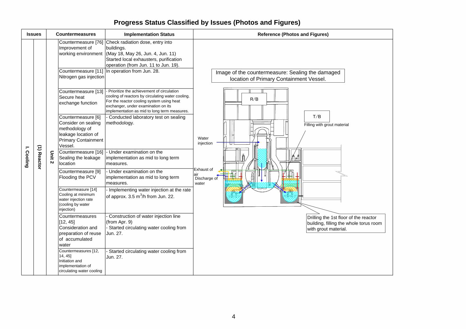
Countermeasure [6]Consider on sealingmethodology ofleakage location ofPrimary ContainmentVessel.
- Conducted laboratory test on sealingmethodology.
Countermeasure [16]Sealing the leakagelocation
- Under examination on theimplementation as mid to long termmeasures.
Countermeasure [9]Flooding the PCV
- Under examination on theimplementation as mid to long termmeasures.
Countermeasure [14]Cooling at minimumwater injection rate(cooling by waterinjection)
- Implementing water injection at the rateof approx. 3.5 m3/h from Jun. 22.
Countermeasures[12, 45]Consideration andpreparation of reuseof accumulatedwater
- Construction of water injection line(from Apr. 9)- Started circulating water cooling fromJun. 27.
Countermeasures [12,14, 45]Initiation andimplementation ofcirculating water cooling
- Started circulating water cooling fromJun. 27.
Progress Status Classified by Issues (Photos and Figures)Issues
I. Cooling
(1) Reactor
Unit 2
Countermeasures
T/B
R/B
Image of the countermeasure: Sealing the damagedlocation of Primary Containment Vessel.
Filling with grout material
Waterinjection
Discharge ofwater
Exhaust ofair
Drilling the 1st floor of the reactorbuilding, filling the whole torus roomwith grout material.
4

Implementation Status Reference (Photos and Figures)Countermeasure [76]Improvement ofworking environment
- Removal of debris, check exposure dose,entry into buildings. (May 18, Jun. 9)- Clearance work using robots (Jul. 1)- Placement of steal boards at truck bay door(Jul. 4)
Countermeasure [11]Nitrogen gasinjection
In operation from Jul. 14.
Countermeasure [13]Secure heatexchange function
- Prioritize the achievement of circulationcooling of reactors by circulating water cooling.For the reactor cooling system using heatexchanger, under examination on itsimplementation as mid to long term measures.
Countermeasure [16]Sealing the leakagelocation
- Under examination on theimplementation as mid to long termmeasures.
Countermeasure [9]Flooding the PCV
- Under examination on theimplementation as mid to long termmeasures.
Countermeasure [14]Cooling at minimumwater injection rate(cooling by waterinjection)
- Implementing water injection at the rateof approx. 9 m3/h from Jun. 24.
Countermeasures[12, 45]Consideration andpreparation of reuseof accumulated water
- Construction of water injection line(from Apr. 16)- Started circulating water cooling fromJun. 27.
Countermeasures [12, 14,45]Initiation andimplementation ofcirculating water cooling
- Started circulating water cooling fromJun. 27.
Progress Status Classified by Issues (Photos and Figures)Issues
I. Cooling
(1) Reactor
Unit 3
CountermeasuresDemolished and removed debris at the truck bay door, which would have been obstacles forinstallation of alternative cooling facilities for Unit 3's reactor.
(After removal May 25) (After removal May 30) (After removal Jun. 4)
Truck bay door/ collapsed outside pillars Truck bay door/ InsideMachine hatch space on the 1st floorof the reactor building
Situation of demolishing and removing debris
Removal of outside pillarsusing wirelessly-controlled
backhoe
Removal of debris usingBrokk
(wired remote control)
Container loading usingshielded forklift
5
Implementation status Reference (Photos and Figures)
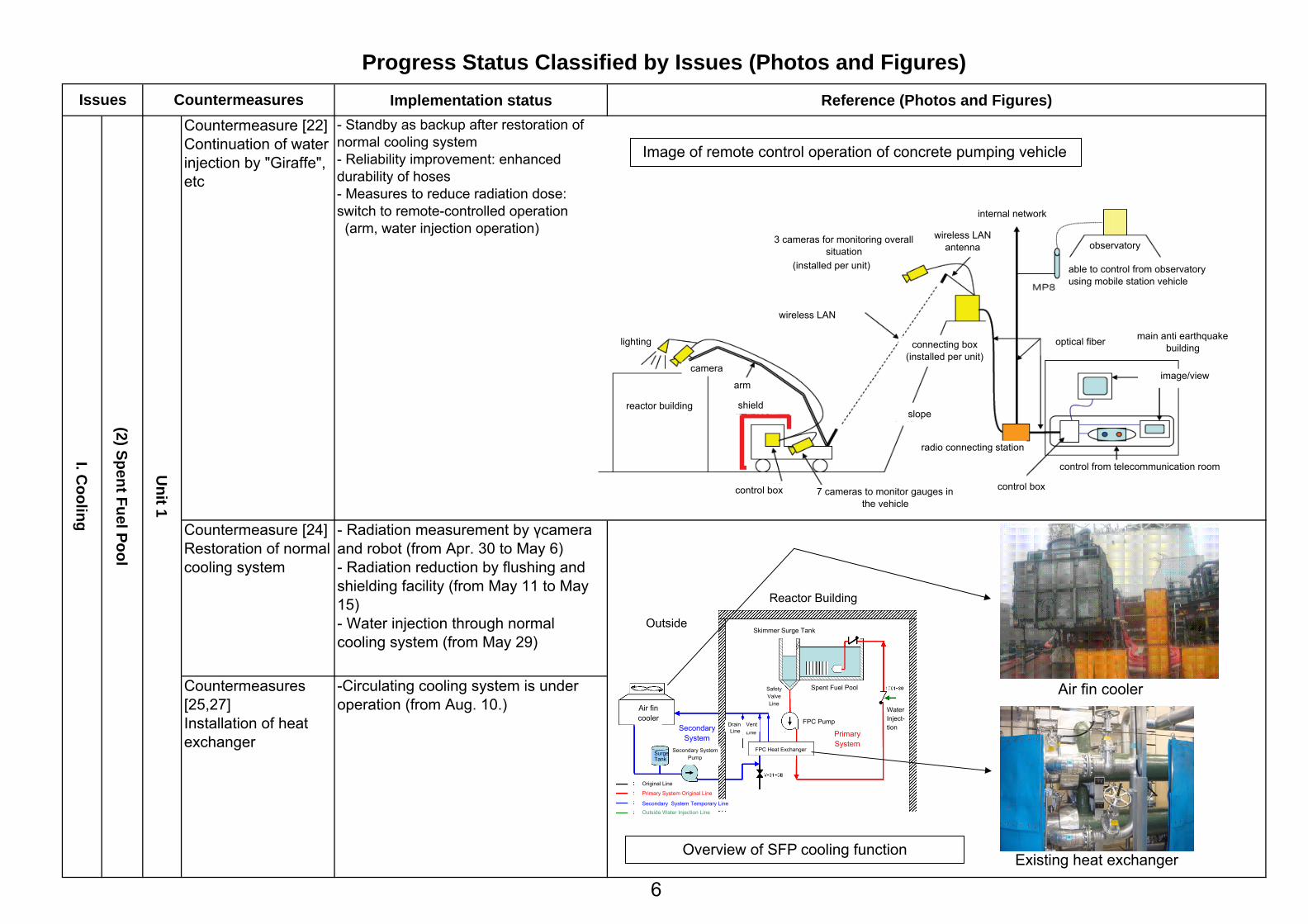
Countermeasure [24]Restoration of normalcooling system
- Radiation measurement by γcameraand robot (from Apr. 30 to May 6)- Radiation reduction by flushing andshielding facility (from May 11 to May15)- Water injection through normalcooling system (from May 29)
Countermeasures[25,27]Installation of heatexchanger
-Circulating cooling system is underoperation (from Aug. 10.)
Countermeasure [22]Continuation of waterinjection by "Giraffe",etc
- Standby as backup after restoration ofnormal cooling system- Reliability improvement: enhanceddurability of hoses- Measures to reduce radiation dose:switch to remote-controlled operation (arm, water injection operation)
Progress Status Classified by Issues (Photos and Figures)Issues
I. Cooling
(2) Spent Fuel Pool
Unit 1
Countermeasures
Image of remote control operation of concrete pumping vehicle
lighting
reactor building
wireless LAN
3 cameras for monitoring overallsituation
(installed per unit)
control box 7 cameras to monitor gauges inthe vehicle
control box
slope
arm
camera
shield
radio connecting station
control from telecommunication room
image/view
main anti earthquakebuilding
observatory
able to control from observatoryusing mobile station vehicle
internal network
connecting box(installed per unit)
optical fiber
wireless LANantenna
Overview of SFP cooling functionExisting heat exchanger
Air fin coolerAir fincooler
SecondarySystem
Secondary SystemPump
SurgeTank
PrimarySystem
FPC Heat Exchanger
Line
SafetyValveLine
DrainLine
Vent
Original Line
Primary System Original Line
Secondary System Temporary LineOutside Water Injection Line
Outside
Reactor Building
Skimmer Surge Tank
Spent Fuel Pool
FPC Pump
WaterInject-tion
wireles
6

Implementation status Reference (Photos and Figures)Countermeasure [23]Restoration ofnormal coolingsystem
- Continuing
Countermeasures[25,27]Installation of heatexchanger
- Installation work of heat exchangercompleted. Circulating cooling systemis under operation (from May 31).
Countermeasure [22]Continuation of waterinjection by "Giraffe"etc
- Standby as backup after restoration ofnormal cooling system- Reliability improvement: enhanceddurability of hoses- Measures to reduce radiation dose:switch to remote-controlled operation
Countermeasure [24]Restoration of normalcooling system
- Confirmation of system integritythrough water level measurement by"Giraffe," etc. (from May 8 to May 15)- Water injection through normalcooling system (from May 16 to Jun.29)
Countermeasures[25,27]Installation of heatexchanger
- Installation work of heat exchangercompleted. Circulating cooling systemis under operation (from Jun. 30).
Unit 3
(2) Spent Fuel Pool
I. Cooling
Progress Status Classified by Issues (Photos and Figures)Issues
Unit 2
Countermeasures
Unit 3 Spent Fuel Pool
Debris in Unit 2 Waste Treatment Building
Unit 3 Heat Exchanger Unit
Unit 2 Heat Exchanger Unit
7
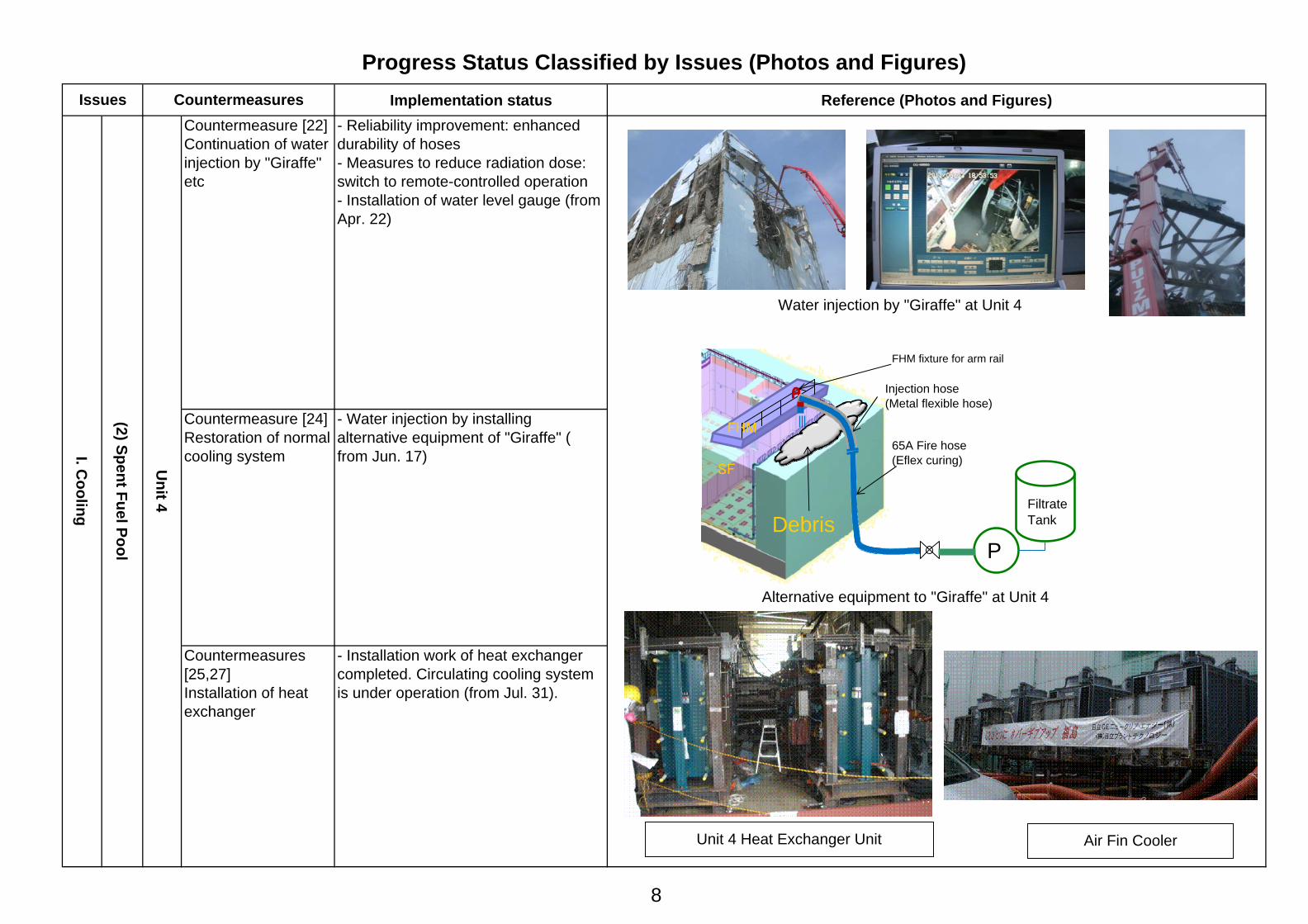
Implementation status Reference (Photos and Figures)Countermeasure [22]Continuation of waterinjection by "Giraffe"etc
- Reliability improvement: enhanceddurability of hoses- Measures to reduce radiation dose:switch to remote-controlled operation- Installation of water level gauge (fromApr. 22)
Countermeasure [24]Restoration of normalcooling system
- Water injection by installingalternative equipment of "Giraffe" (from Jun. 17)
Countermeasures[25,27]Installation of heatexchanger
- Installation work of heat exchangercompleted. Circulating cooling systemis under operation (from Jul. 31).
Progress Status Classified by Issues (Photos and Figures)Issues
I. Cooling
(2) Spent Fuel Pool
Unit 4
Countermeasures
Alternative equipment to "Giraffe" at Unit 4
FiltrateTank
FHM
SF
PDebris
Injection hose(Metal flexible hose)
FHM fixture for arm rail
65A Fire hose(Eflex curing)
Water injection by "Giraffe" at Unit 4
Unit 4 Heat Exchanger Unit Air Fin Cooler
8

Progress Status Classified by Issues (Photos and Figures)Implementation status Reference (Photos and Figures)
Countermeasures [37, 39,42] Securing sufficientplaces to storecontaminated water
- Transferring to Centralized WasteTreatment Facility (Process MainBuilding and High-temperatureIncineration Building) after checkingnon-existence of water leakage
o Process Main Building: After checking non existence ofwater leakage etc., resumedtransferring accumulated water fromUnit 2 Turbine Building. (April 19)
o High-temperature IncinerationBuilding: After checking non existence ofwater leakage etc., resumedtransferring accumulated water fromUnit 3 Turbine Building. (May 17)
Issues Countermeasures
High level
(3) Accum
ulated Water
II. Mitigation
T/B at Unit 3 T/B at Unit 4T/B at Unit 1 T/B at Unit 2
Unit 1R/B
Unit 2R/B
Unit 3R/B
Unit 4R/B
Vertical Shaftat Unit 2
Hatch atUnit 3
Centralized WasteTreatment Facility
ProcessMainBuilding
High-temperatureIncinerationBuilding
<Transferring into Centralized Waste Treatment Facility>
Tanks to receive processed water(H1 area)
Underground tanks for processed water(Highly contaminated water)
9

Progress Status Classified by Issues (Photos and Figures)Implementation status Reference (Photos and Figures)
Countermeasure[64]Consideration of mitigationof contamination in theocean
- Completed setting up silt fence (Apr. 14)- Preparation construction for setting steelpipe sheet piles[Completed removing curtain wall]
- Purification of sea water by circulatingpurification system (from Jun. 13)- Completed setting up sliding concrete wall atintake of Unit 1 to 4 (Jun. 29)
- Started shipping steel pipe sheet pile (fromAug. 10)( Shipping steel pipe sheet pile the port inorder to implement translucent preventionwork and repair the blocks damaged bytsunami at the south side of intake canal ofUnit 1 to 4)
Countermeasure [65]Containment of high levelradioactive water
- Closure of sea water piping verticalshaft Unit 2: completed on Jun. 2, Unit 3: completed on May 26, Unit 4: completed on Apr. 6- Closure of pits and others Unit 1: completed on May 17 Unit 2: completed on Jun. 9 Unit 3: completed on Jun. 10 Unit 4: completed on Jun. 10
Issues Countermeasures
II. Mitigation
(3) Accum
ulated Water
High level
取水口角落しの設置状況(2号機の状況) 取水口角落し(作業状況)
Closure of sea water piping vertical shaft(left: before closure, right: after closure)
Sliding concrete wall at intake(Setting work)
Sliding concrete wall at intake (Unit 2)
Closure of pit(left: before closure, right: after closure)
<Appearance of the system><Adsorption of cesium by zeolite>
zeolite
Watering pipe
pump
Shipping steel pipe sheet pile
10

Progress Status Classified by Issues (Photos and Figures)Implementation status Reference (Photos and Figures)
[Decontamination of Contaminated Water]Started on Jun. 17- Cesium adsorption instruments (Kurion) + Radioactivity treatment apparatus(Areva) Processing started on Jun. 17- 2nd Cesium adsorption apparatus(SARRY): Planned to start on Aug. 18
[Desalting of Contaminated Water]- Water Desalinations (RO method): Processing started on Jun. 17 Second phase of constructioncompleted on Jul. 20- Water Desalinations (Distillingequipment): Start treatment on Aug. 7 (Toshibaportion) Plan to start treatment on Aug. 20(Areva portion)
[Storage of sludge waste]- Storing sludge waste in the pellet storagetank- Additional sludge waste storage tanksare under preparation
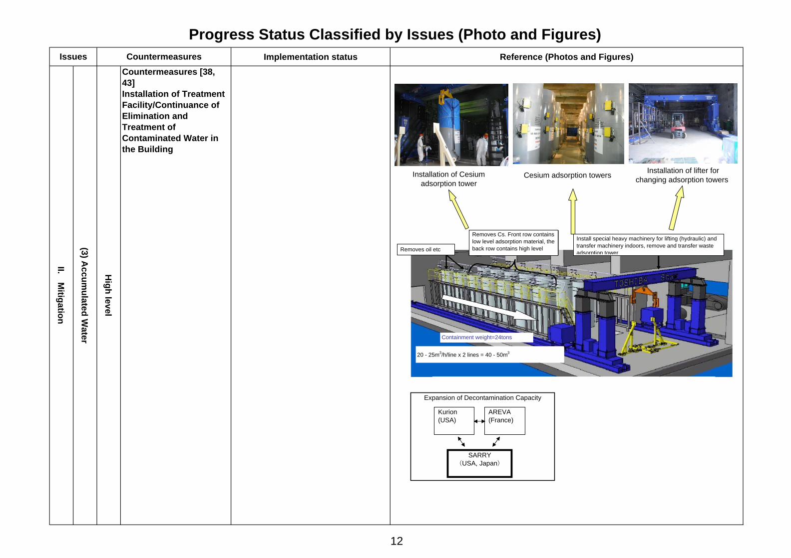
Countermeasures [38,43]Installation of TreatmentFacility/Continuance ofElimination andTreatment ofContaminated Water inthe Building
Issues Countermeasures
II. Mitigation
(3) Accum
ulated Water
High level
Tanks for receivingprocessed water
Scrubber
Coolingtower
Preheatedundilutedsolution tank Vaporizing
condenser
Retentionsolutiontank
Chemicaltank
(Example: Toshiba)
III. Decontaminationapparatus
IV. Desalinationapparatus 1
(Reverse osmosis)
V. Desalinationapparatus 2(distillation)
II. Cesium adsorptionapparatus
<Decontamination flow of contaminated water>
I. Oil separators
Oil Tank
Nuclidecoprecipitation(adsorption)
Coagulationsettling
Waste Liquid Tanks
~~~~
Cesiumabsorption tower
PostFilter
11
Progress Status Classified by Issues (Photo and Figures)Implementation status Reference (Photos and Figures)
Countermeasures [38,43]Installation of TreatmentFacility/Continuance ofElimination andTreatment ofContaminated Water inthe Building
Issues Countermeasures
High level
(3) Accum
ulated Water
II. Mitigation
Installation of lifter forchanging adsorption towers
Expansion of Decontamination Capacity
AREVA(France)
Kurion(USA)
SARRY(USA, Japan)
Cesium adsorption towersInstallation of Cesiumadsorption tower
Removes oil etc
Removes Cs. Front row containslow level adsorption material, theback row contains high level
Install special heavy machinery for lifting (hydraulic) andtransfer machinery indoors, remove and transfer wasteadsorption tower
Containment weight=24tons
20 - 25m3/h/line x 2 lines = 40 - 50m3
12

Progress Status Classified by Issues (Photos and Figures)Implementation status Reference (Photos and Figures)
Increase of storage capacity and continuationof decontamination of contaminated water- Installation of tanks for processed water: Waste liquid RO Supply B Area 6,200t (May 31) RO processed water temporary storage tank D Area 5,000t (May 10) RO condensed water temporary storage tank E Area 8,000t (May 22) RO condensed water storage tank H Area 32,000t (Aug 15) Evaporation treatment fresh water storagetank H Area 5,000t (Jul 21)Evaporation waste liquid storage tankH Area 5,000t (Jul 31)- Low level tank F Area 12,200t (May 31)- Megafloat 10,000t (May 21)
Utilization of decontaminant (zeolite) Setting in water, self-circulation and adsorption of Cesium by zeolite
Decontamination of accumulated water in Unit 6 T/B after transferring to receiver tanks for low level water
Full-scale operation (from May 1)
Issues Countermeasures
II. Mitigation
(3) Accum
ulated Water
Low level
Countermeasure [40, 41]Increase storagecapacity /decontamination
<Megafloat> <F Area Tanks><Square shape tanks> <Round shape tanks>
Decontaminant (zeolite)
13
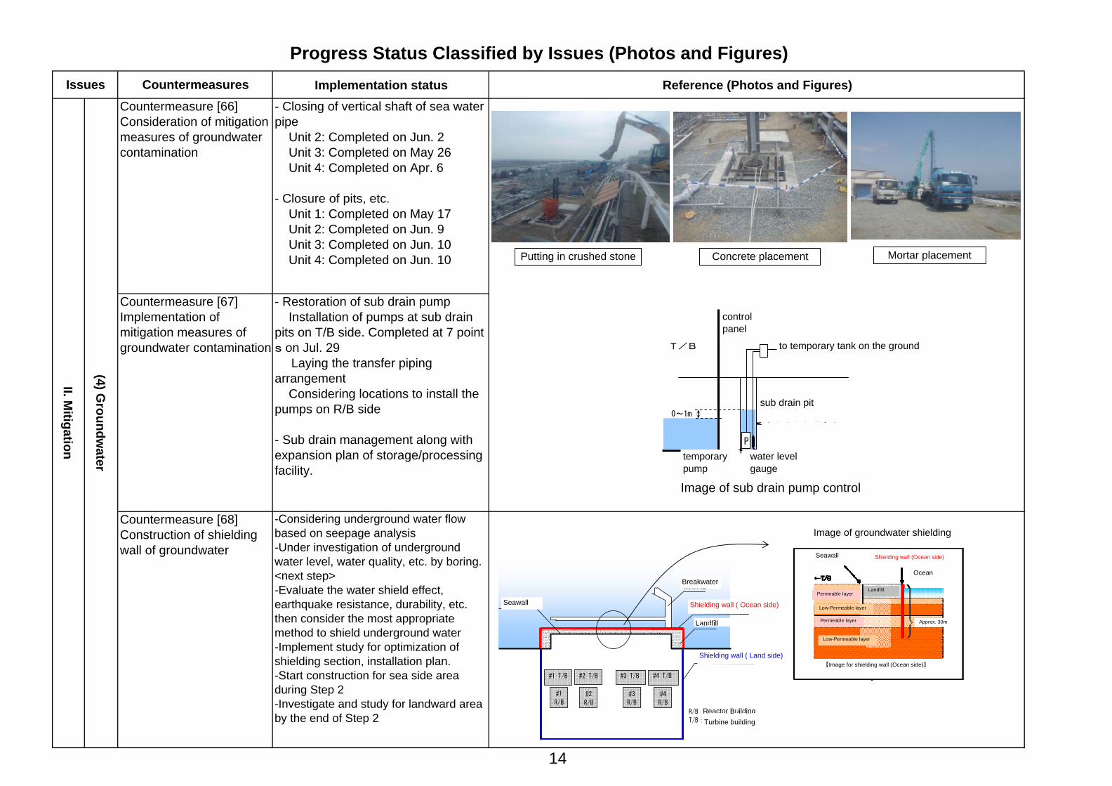
Implementation status Reference (Photos and Figures)- Closing of vertical shaft of sea waterpipe Unit 2: Completed on Jun. 2 Unit 3: Completed on May 26 Unit 4: Completed on Apr. 6
- Closure of pits, etc. Unit 1: Completed on May 17 Unit 2: Completed on Jun. 9 Unit 3: Completed on Jun. 10 Unit 4: Completed on Jun. 10
-Considering underground water flowbased on seepage analysis-Under investigation of undergroundwater level, water quality, etc. by boring.<next step>-Evaluate the water shield effect,earthquake resistance, durability, etc.then consider the most appropriatemethod to shield underground water-Implement study for optimization ofshielding section, installation plan.-Start construction for sea side areaduring Step 2-Investigate and study for landward areaby the end of Step 2
Countermeasure [66]Consideration of mitigationmeasures of groundwatercontamination
II. Mitigation
Progress Status Classified by Issues (Photos and Figures)Issues Countermeasures
(4) Groundw
ater
Countermeasure [68]Construction of shieldingwall of groundwater
Countermeasure [67]Implementation ofmitigation measures ofgroundwater contamination
- Restoration of sub drain pump Installation of pumps at sub drainpits on T/B side. Completed at 7 points on Jul. 29 Laying the transfer pipingarrangement Considering locations to install thepumps on R/B side
- Sub drain management along withexpansion plan of storage/processingfacility.
P
仮設ポンプ
0~1m
T/B 地上仮設タンクへ
水位計
制御盤
サブドレンピット
サブドレンポンプ管理イメージ図
Image for groundwater shielding
Seawall Shielding wall (Ocean side)
【Image for shielding wall (Ocean side)】
Ocean
Approx. 30m
LandfillPermeable layer
Permeable layer
Low-Permeable layer
Low-Permeable layer
Image for groundwater shielding
Seawall Shielding wall (Ocean side)
【Image for shielding wall (Ocean side)】
Ocean
Approx. 30m
LandfillPermeable layer
Permeable layer
Low-Permeable layer
Low-Permeable layer
Image of sub drain pump control
temporarypump
water level gauge
sub drain pit
to temporary tank on the ground
controlpanel
Putting in crushed stone Concrete placement Mortar placement
Image of groundwater shielding
#2
R/B
#3
R/B
#4
R/B
#1
R/B
#1 T/B #2 T/B #3 T/B #4 T/B
R/B:原子炉建屋
T/B:タービン建屋
遮水壁(海側)
遮水壁(陸側)
埋立
防波堤
既設護岸
Breakwater
Landfill
Shielding wall ( Ocean side)Seawall
Shielding wall ( Land side)
Turbine buildingReactor Building
14

Implementation Status Reference (Photos and Figures)
(5) Atm
osphere / Soil
Progress Status Classified by Issues (Photos and Figures)
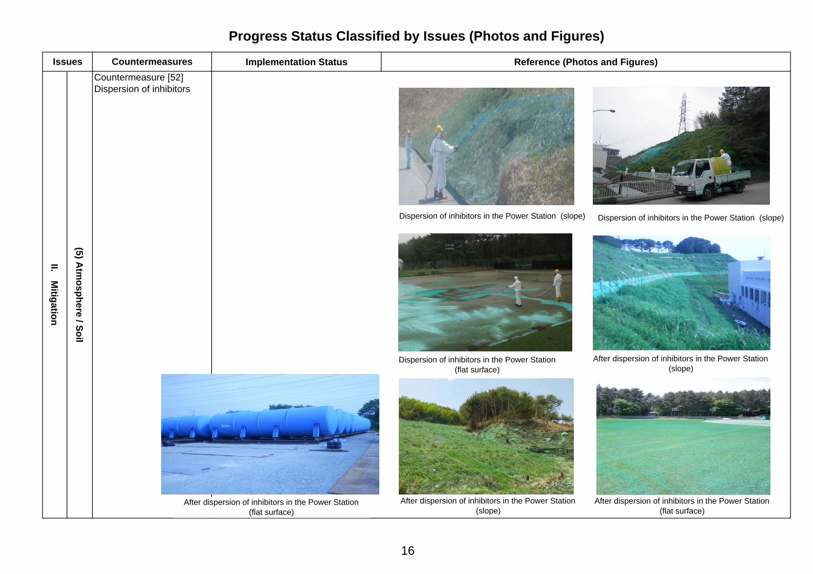
Issues CountermeasuresCountermeasure [52]Dispersion of inhibitors
II. Mitigation
[Present Status]Completed dispersion of inhibitor
○Record of dispersion : Approx. 560,000m2
<Inside power station (flat land andslope)> : Approx. 400,000m2
-Test dispersion (Apr. 1 to Apr. 25) : Approx. 30,000m2
-Full dispersion (Apr. 26 to Jun. 28) : Approx. 370,000m2
<Around buildings> : Approx. 160,000m2
-Dispersion using crawler dump truck(Apr. 26 to Jun. 27) Around buildings of Unit 1 to 4, 5and 6 : Approx. 120,000m2
-Dispersion by bending spray towervehicle (May 27 to Jun. 4, Jun. 10) Turbine building of Unit 1 to 4, roofand wall of reactor building of Unit 2 : Approx. 30,000m2
-Dispersion by concrete pumpingvehicle (Zebra) (Jun. 8,9,18) Roof and wall of reactor building ofUnit 1,3,4 : Approx. 10,000m2
Hereafter, we keep monitoring status ofsolidification and others at dispersedarea.
Dispersion of inhibitors around buildings ofUnit 1 to 4 by crawler dump
Dispersion of inhibitors by bending spray tower vehicle
Dispersion of inhibitors in the Power Station (slope)
15
Implementation Status Reference (Photos and Figures)
(5) Atm
osphere / Soil
Progress Status Classified by Issues (Photos and Figures)
Issues CountermeasuresCountermeasure [52]Dispersion of inhibitors
II. Mitigation
発電所構内(平面)への散布後After dispersion of inhibitors in the Power Station(flat surface)
Dispersion of inhibitors in the Power Station (slope) Dispersion of inhibitors in the Power Station (slope)
After dispersion of inhibitors in the Power Station(slope)
Dispersion of inhibitors in the Power Station(flat surface)
After dispersion of inhibitors in the Power Station(flat surface)
After dispersion of inhibitors in the Power Station(slope)
16

Implementation Status Reference (Photos and Figures)- In order to mitigate exposure dose ofthe workers and improve workefficiency at the site, we have startedremoving the debris after storing themin the containers using remote-controlled heavy machinery (hydraulicshovel, crawler dump, bulldozer) (fromApr. 6).
- Almost all of the debris in highly-radioactive area, outside the buildingsof Unit 1 to 4 (airborne radiation10mSv/h or higher) are removed .
<Record of removing debris as of Aug.17>- Approx.700 containers of debris areremoved.
<Plan for further implementation>- We will continue removing outsidedebris, that hinders work.
II. Mitigation
Progress Status Classified by Issues (Photos and Figures)Issues Countermeasures
(5) Atm
osphere / Soil
Countermeasure [53]Removal of debris
Removing debris with remote-controlled heavy machinery
(Container:3.2×1.6×1.1m、Approx.4m3)
Around reactor building of Unit 1 (Jun. 9)
Road at the ocean-side near Unit 1 Turbine BuildingBottom of the slope at the south side of Centralized Waste TreatmentF ilit
Between reactor buildings of Unit 2 and Unit 3Around reactor building of Unit 1
17
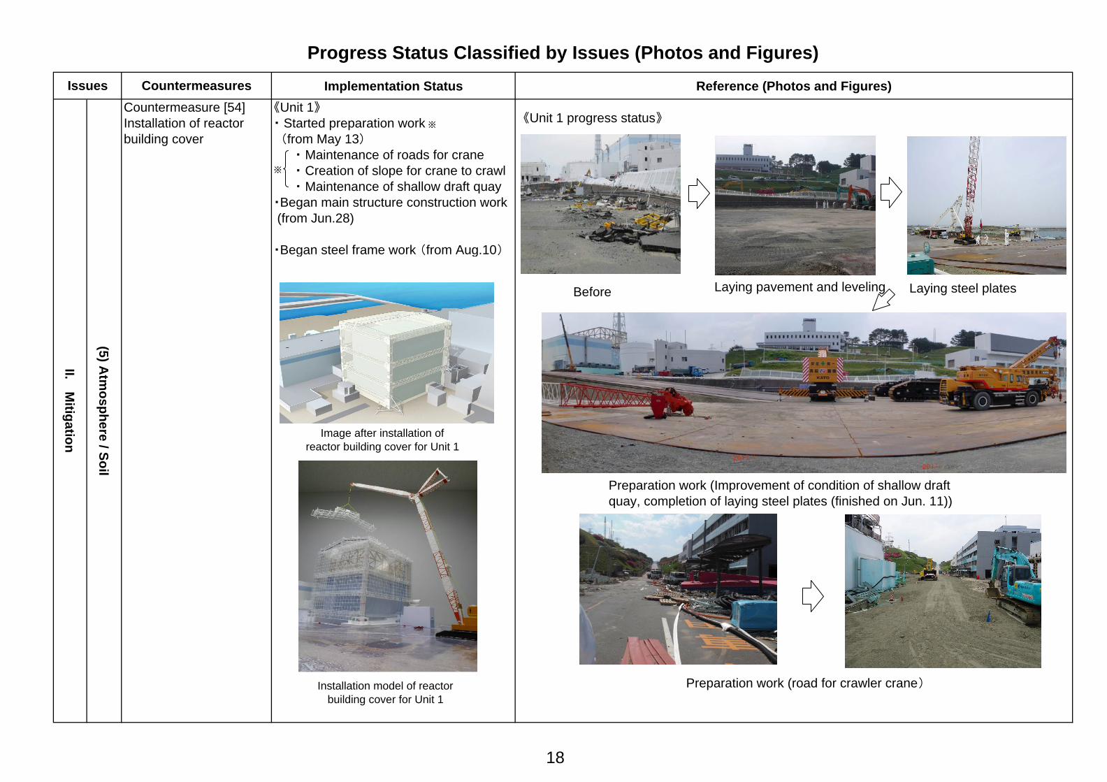
Implementation Status Reference (Photos and Figures)《Unit 1》・ Started preparation work ※
(from May 13) ・ Maintenance of roads for crane ・ Creation of slope for crane to crawl ・ Maintenance of shallow draft quay・Began main structure construction work (from Jun.28)
・Began steel frame work (from Aug.10)
Progress Status Classified by Issues (Photos and Figures)Issues Countermeasures
(5) Atm
osphere / Soil
II. Mitigation
Countermeasure [54]Installation of reactorbuilding cover
Image after installation ofreactor building cover for Unit 1
※
Installation model of reactorbuilding cover for Unit 1
Preparation work (Improvement of condition of shallow draftquay, completion of laying steel plates (finished on Jun. 11))
Before Laying pavement and leveling
Preparation work (road for crawler crane)
《Unit 1 progress status》
Laying steel plates
18

Implementation Status Reference (Photos and Figures)
II. Mitigation
(5) Atm
osphere / Soil
Progress Status Classified by Issues (Photos and Figures)Issues Countermeasures
Countermeasure [54]Installation of reactorbuilding cover
Status of preparation work (shallow draft quay~road for crawler crane)
Temporary assembly of reactor building cover for Unit 1 (at Onahama Port) Assembly of steel frames
Assembly of steel frames
19

Implementation Status Reference (Photos and Figures)<Unit 3,4>- Commencement of preparation work Unit 3; from Jun. 20 Unit 4; from Jun. 24
(5) Atm
osphere / Soil
Progress Status Classified by Issues (Photos and Figures)
II. Mitigation
Issues CountermeasuresCountermeasure [84]Removal of debris on topof reactor buildings
Preparation work for reactor building cover for Unit 3 Preparation work for reactor building cover for Unit 4
Maintenance of roads for large-size crane Maintenance of working area for large-size crane
Assembling heavy machinery for dismantling debris around buildings
Maintenance of working area for assembling steel frames Removal of debris
Assembling heavy machinery for dismantling debris around buildings
20

Countermeasures Implementation Status Reference (Photos and Figures)
Progress Status Classified by Issues (Photos and Figures)Issues
Countermeasure [60,61]Expansion, enhancement andannouncement of monitoring
III. Monitoring/D
econtamination
(6) Measurem
ent, Reduction and D
isclosure
Continue monitoring in and out of the power station
[Land area]<Monitoring within 20km radius of the periphery>・ Monitoring of aerial radiation dose rate at 50 points by Utility Support Team (once a week)・ Land sampling at 50 points and additional points (approx. 50 points) by Utility Support Team (Jun. 10, 13, 30, Jul. 2 and 8)・ Dust sampling at 5 points near 10 km radius of the periphery (Aug. 5)・ Monitoring at the time of nitrogen injection to the PCV of Unit 3 (Jul.13~29)
<Monitoring within the site>・ Monitoring of airborne radioactivity concentration around the West Gate (everyday)・ Monitoring of radioactivity concentration at the upper part of reactor buildings by a concrete pumper, etc.(every 1 month): Unit 1 (May 22, Jun. 22, and Jul. 24), Unit 4 (May 23, Jun.18), Unit 3 (Jun.13, Jul. 12, 13, and 23), Unit 2 (Jul.22)・Measurement of airborne radioactivity concentration at 12 points in the site (once a week,once a month)・Measurement of radioactive material fallout in the air (once or twice a month) at 10 points outside of the site・Mitigation measures on backgrounds of monitoring posts (mitigation of the impact from land etc.) MP8 (done on May 20), MP3 (done on May 23)
Soil sampling by the Utility Support Team (Within 20 km radius)
福島第一 空気中の放射性物質濃度の推移
Sampling by concretepumping vehicle
20km圏内の空間放射線量率測定結果(測定日:平成23年8月5日)
1.0E-07
1.0E-06
1.0E-05
1.0E-04
1.0E-03
1.0E-02
1.0E-01
3/19 3/26 4/2 4/9 4/16 4/23 4/30 5/7 5/14 5/21 5/28 6/4 6/11 6/18 6/25 7/2 7/9 7/16 7/23 7/30 8/6
I-131(合計値)
Cs-134(合計値)
Cs-137(合計値)
告示濃度(Bq/cm3)Cs-137 3E-5Cs-134 2E-5I-131 5E-6
Trend of density of radioactive materials in the air at Fukushima Daiichi
(Total)
(Total)
(Total)
Notificationconcentration
WSW
SW
49 4.8
40 2.0
39 4.0
32 1.7
43 3.1
1 0.5 6
1.8
13 5.0
15 18.6
36 29.6 34
3.4
45 11.0
18 7.0
41 1.9
33 1.2
31 1.2
20 22.2
12 7.5 7
1.8
25 3.5 24
1.0
44 2.2
SSW
S
30 24.1
23 20.0 28
10.2
27 19.4
29 58.6
10 8.9
11 4.1
48 0.8
46 16.3
50 18.0
W
37 73.6
35 14.6 26
3.6 38
11.2
47 34.6
42 4.1
22 7.3
WNW
2 0.6
17 8.5
21 20.9
8 25.6
9 8.2
19 33.6
N
NNW
NW
4 0.6
3 0.9
5 0.6
14 24.8
16 5.7
20km
10km
5km
3km
5km
3km
10km
20km Upper: Point No.Lower: Radiation dose rate (μSv/h)
Measurement result of aerial radiation dose rate ofwithin 20 km radius (date: Aug. 5, 2011)
21
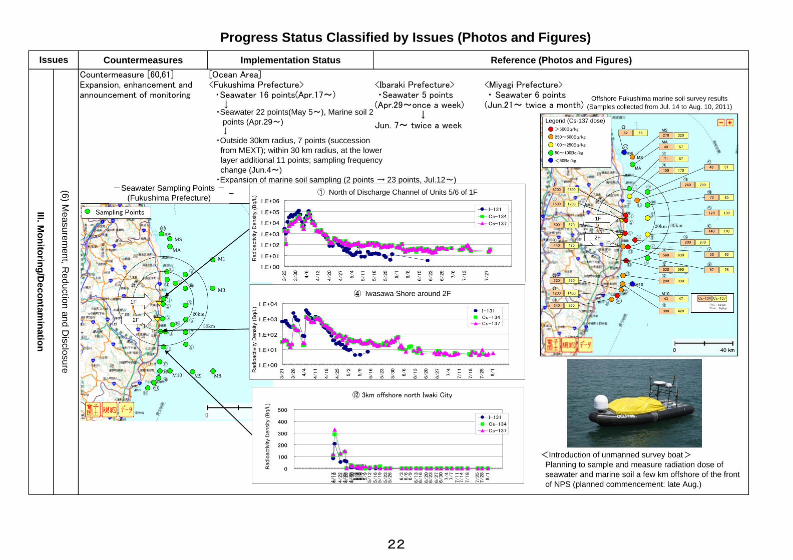
Countermeasures Implementation Status Reference (Photos and Figures)Countermeasure [60,61]Expansion, enhancement andannouncement of monitoring
<Ibaraki Prefecture> <Miyagi Prefecture> ・Seawater 5 points ・ Seawater 6 points(Apr.29~once a week) (Jun.21~ twice a month) ↓Jun. 7~ twice a week
Progress Status Classified by Issues (Photos and Figures)
(6) Measurem
ent, Reduction and D
isclosure
III. Monitoring/D
econtamination
[Ocean Area]<Fukushima Prefecture> ・Seawater 16 points(Apr.17~) ↓
Issues
-福島県 前面海域採取点-
① ②
⑦
⑧
⑩
③
④
⑨
⑪
⑫
⑯
⑰
⑱
⑲ ⑳
M10
⑬
⑭ ⑮
⑤
⑥
MA
MS
21
22
凡例(Cs-137 濃度による)
>500Bq/kg
250~500Bq/kg
100~250Bq/kg
50~100Bq/kg
<50Bq/kg
30km 20km 福島第一
福島第二
○22 62 66
MS270 320
⑭150 170
⑮260 290
⑩73 85
⑥140 170
⑦50 60
⑧67 76
⑳330 390
○21
1200 1400
⑱240 260
①8700 9600
②1500 1700
③500 570
④440 490
Cs-134 Cs-137
(単位:Bq/kg)(Unit::Bq/kg)
MA49 57
⑤120 130
M1043 47
⑲390 420
⑬71 87
⑪560 630
⑨48 51
⑰290 330
⑫520 590
⑯800 870
① ②
⑦
⑧
⑩
③
④
⑨
⑪
⑫
⑯
⑰
⑱
⑲ ⑳
M3
M8 M9 M10
⑬
⑭ ⑮
⑤
⑥
M1
MA
MS
21
22
海水調査点
30km
20km
福島第一
福島第二
1.E+00
1.E+01
1.E+02
1.E+03
1.E+04
1.E+05
1.E+06
3/23
3/30
4/6
4/13
4/20
4/27
5/4
5/11
5/18
5/25
6/1
6/8
6/15
6/22
6/29
7/6
7/13
7/27
① 福島第一 5,6号機放水口北側
放射
能濃
度(Bq/L) I-131
Cs-134
Cs-137
1.E+00
1.E+01
1.E+02
1.E+03
1.E+04
3/21
3/28
4/4
4/11
4/18
4/25
5/2
5/9
5/16
5/23
5/30
6/6
6/13
6/20
6/27
7/4
7/11
7/18
7/25
8/1
④ 福島第二 岩沢海岸付近
放射
能濃
度(Bq/
L)
I-131
Cs-134
Cs-137
0
100
200
300
400
500
4/17
4/18
4/22
4/25
4/26
4/29
4/30
5/2
5/3
5/4
5/5
5/6
5/7
5/9
5/12
5/16
5/19
5/23
5/26
6/3
6/6
6/9
6/13
6/16
6/20
6/23
6/27
6/30
7/4
7/7
7/11
7/14
7/18
7/25
7/28
8/1
⑭ いわき市北部沖合3km
放射
能濃
度(Bq/
L)
I-131
Cs-134
Cs-137
⑫
・Seawater 22 points(May 5~), Marine soil 2 points (Apr.29~) ↓・Outside 30km radius, 7 points (succession from MEXT); within 30 km radius, at the lower layer additional 11 points; sampling frequency change (Jun.4~)・Expansion of marine soil sampling (2 points → 23 points, Jul.12~)
Offshore Fukushima marine soil survey results(Samples collected from Jul. 14 to Aug. 10, 2011)
Legend (Cs-137 dose)
① North of Discharge Channel of Units 5/6 of 1F
Rad
ioac
tivity
Den
sity
(Bq/
L)
④ Iwasawa Shore around 2F
Rad
ioac
tivity
Den
sity
(Bq/
L)
⑫ 3km offshore north Iwaki City
Rad
ioac
tivity
Den
sity
(Bq/
L)
-Seawater Sampling Points -(Fukushima Prefecture)
Sampling Points
<Introduction of unmanned survey boat> Planning to sample and measure radiation dose of seawater and marine soil a few km offshore of the front of NPS (planned commencement: late Aug.)
1F
2F
2F
1F
22

Implementation Status Reference (Photos and Figures)
-Temporary DGs were moved to theupland (Apr. 15)-Securing redundancy of waterinjection line (by Apr. 15)-Setting fire engines in the upland (byApr. 18)
-Started installation of temporary tidebarrier on May 18 and completedon June 30
Progress Status Classified by Issues (Photos and Figures)Issues
IV. Counterm
easures for aftershocks, etc.
(7) Tsunami, reinforcem
ent, etc.
CountermeasuresCountermeasure [69]Countermeasures againsttsunami
Countermeasure [70]Enhancement ofcountermeasures againsttsunami
仮設防潮堤設置予定範囲(イメージ)
仮設防潮堤設置状況(4)
O.P. +14m
仮設防潮堤設置状況(1) 仮設防潮堤設置状況(2)
仮設防潮堤設置状況(3)
Planned temporary tide barrier(white dotted line, image)
Temporary tide barrier (4)
O.P. +14m
Temporary tide barrier (1) Temporary tide barrier (2)
Temporary tide barrier (3)
Cross-section of temporary tidebarrier (image)
Water proof sheetContainer filled withstones
Areas for temporarytide barriers (planned)
Seaside area(height: 4m)
Main building area(height: 10m)
23

Implementation Status Reference (Photos and Figures)Countermeasure [26]Installation ofsupporting structureunder the bottom ofspent fuel pool
- Soundness of structure was analyzedand evaluated
- Securing the route to the area toinstall supporting structure (removing debris, assembling ascaffolding at hatch, removing shieldblocks)- Removing obstacles at the area andinstalling shielding- Completion of installing steel pillars(Jun. 20)- Completion of concrete placement(Jul. 26)- Completion of pouring grout(completion of work) (Jul. 30)
IV. Counterm
easures for aftershocks, etc.
(7) Tsunami, reinforcem
ent, etc.
Progress Status Classified by Issues (Photos and Figures)Issues
Unit 4
Countermeasures
Steel pillar installation Concrete wall installation
Outline ofsupportingstructure
installation
Completion of steel pillarinstallation (Jun. 20)
Installation status ofreinforcing mesh
Installation of supporting structureunder the bottom of spent fuel pool
Installation of concreteshuttering
Completion of pouringgrout (Jul. 30)
Removing debris
Removing debris at truck-bay door
Securing route
Assembling a scaffolding at hatch
24

Implementation Status Reference (Photos and Figures)
- Maintenance of equipment- Implementing water injection trainingby connecting slurry production facilityand concrete pumping vehicle"Elephant-3" (Jun. 16 and 17)- Making procedure documents andconfirming organizational structure(Jun. 30)
Progress Status Classified by Issues (Photos and Figures)Issues Countermeasures
IV. Counterm
easures for aftershocks, etc.
(7) Tsunami, reinforcem
ent, etc.
Countermeasure [72]Preparation of variouscountermeasures forradiation shielding
<Utilization of Slurry>- Slurry production facility, transferpipe, concrete pumping vehicles havebeen installed (May 17)
Installation of equipment at Fukushima Daini Nuclear Power Station
Transfer pipe
Slurry production facilityOverview of the facility
Installation of slurry plantat Fukushima Daiichi
Preparation of equipment (sand)
"Elephant-3"
Placement of equipment at Fukushima Daiichi Nuclear Power Station
High pressure concretepumping vehicle
25

Implementation Status Reference (Photos and Figures)- Improvement of meals, upgrade oflodging facility- Securing water for daily use
- Expansion of temporary dormitory- Increasing available amount of waterfor daily use
(8) Living/working environm
ent
Countermeasure [75]Continuing andenhancement ofimprovement of workers'life/work environment
Progress Status Classified by Issues(Photos and Figures)
Issues CountermeasuresCountermeasure [74]Improvement of workers'like/work environment
V. Environment Im
provement
Drinking waterBunk bed (whole) Shower roomBunk bed
Outside (1)
Inside (1)
Full view
Inside (2) Inside (3)
Inside (4)Inside (5) Inside (6)
Dormitory
Fukushima Daini Gym
26
Implementation Status Reference (Photos and figures)
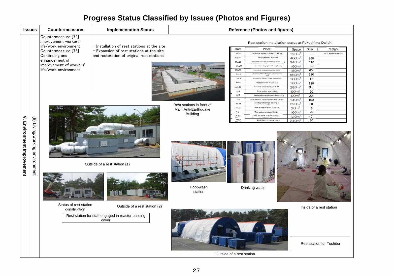
- Installation of rest stations at the site- Expansion of rest stations at the siteand restoration of original rest stations
(8) Living/working environm
ent
Progress Status Classified by Issues (Photos and Figures)Issues Countermeasures
Countermeasure [74]Improvement workers'life/work environmentCountermeasure [75]Continuing andenhancement ofimprovement of workers'life/work environment
V. Environment Im
provement
協力企業(東芝)の休憩所
休憩所の外観
休憩所の内部
飲料水足洗い場
休憩所の外観(1)
休憩所の設置状況 休憩所の外観(2)
Rest stations in front ofMain Anti-Earthquake
Building
Rest station installation status at Fukushima Daiichi
Date Place Space Spec RemarkApr.22
May10
May13
May28
May29
Jun.9
Jun.9
Jun.9
Jun.28
Jul.1
Jul.1
Jul.2
Jul.23
Jul.26
Aug.1
Aug.1
Aug.4
1st floor of service building of Unit 5/6
Rest station for Toshiba
Rest station in front of Main Anti-Earthquake building
Rest station in Company Center Training Building
Rest station in Company Center Welfare Building
Rest station of former Emergency Response measureRoom
Rest station for Operators of Water treatment facility
Rest station for Hitachi GE
2nd floor of service building of Unit5/6
Rest station near heliport
Rest station near Forest of wild birds
Rest station for the Unit1 reactor building cover
2nd floor of service building ofUnit1/2
Rest station at Main Entrance
Rest station at sludge facilityPrefab rest station for staff in charge of
coverage
Rest station for work space
260110606018012
120902020100606
704030
Jul.1~ as Medical room
Outside of a rest station (1)
Outside of a rest station (2)Status of rest stationconstruction
Rest station for staff engaged in reactor buildingcover
Foot-washstation
Drinking water
Outside of a rest station
Inside of a rest station
Rest station for Toshiba
27
Implementation Status Reference (Photos and figures)
(8) Living/working environm
ent
Progress Status Classified by Issues (Photos and Figures)Issues Countermeasures
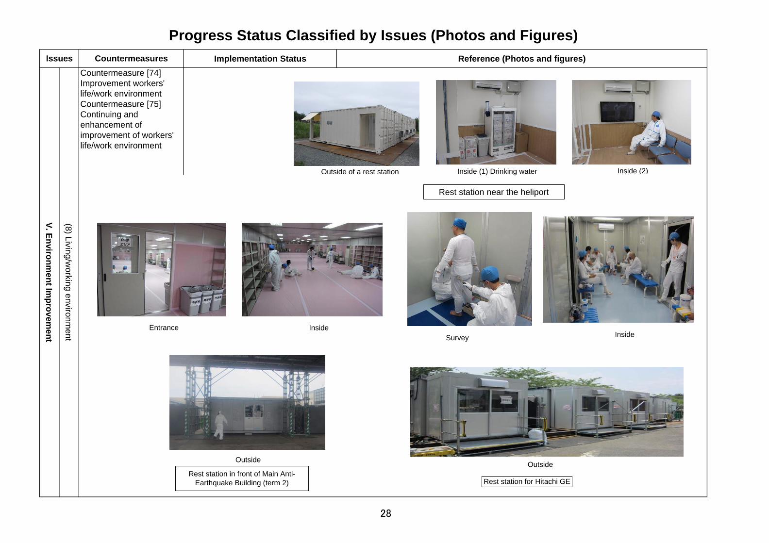
Countermeasure [74]Improvement workers'life/work environmentCountermeasure [75]Continuing andenhancement ofimprovement of workers'life/work environment
V. Environment Im
provement
Rest station for Hitachi GE
Inside
Outside
Entrance Inside
Rest station near the heliport
内部(2)Inside (1) Drinking waterOutside of a rest station
Outside
Survey
Inside (2)
Rest station in front of Main Anti-Earthquake Building (term 2)
28

Implementation Status Reference (Photos and figures)- Improvement of protective equipmentProtective equipment appropriate towork environment is provided toworkers in order to secure safetyduring radiation related work.
(9) Radiation control / M
edical care
Progress Status Classified by Issues (Photos and Figures)Issues Countermeasures
Countermeasure [77]Enhancement ofRadiation ControlCountermeasure [78]Continuing Enhancementof Radiation Control
V. Environment Im
provement
Special protective gear:Protective suit which can beexpected to shield beta ray andlow-energy gamma ray
Closed-circuit oxygen breathing apparatus:It can realize a long 120-minute usage, circulatingaspirated air with oxygen inside the cylinder.It is a suitable for usage in oxygen-less hazardousarea.
Half-faced mask:In case that radioactivitydensity is low and stable,workers put on half-facemasks, not full-face, (withgoggles), which enables tolighten the workload ofworkers.
Respiratory protective device with electric fan:The mask can blow in cleaned air which is filteredwith electric fan. Internal pressure is kept higherthan environmental pressure in order to reducethe risk of inhaling particulate. Also, it realizes tobreathe freely and lighten loss of bodily strength.
*Source: vendor catalogue
*Source: vendor catalogue
*Source: vendor catalogue
*Source: vendor catalogue
Hood mask;Keeping the inner pressure positive, the maskprevents influx of outer air. Continuous ventilationhelps exhausting the inner humidity and preventsheat injuries.
*Source: vendor catalogue
29
Implementation status Reference (Photos and Figures)
(9) Radiation C
ontrol/Medical C
are
Progress Status Classified by Issues (Photos and Figures)
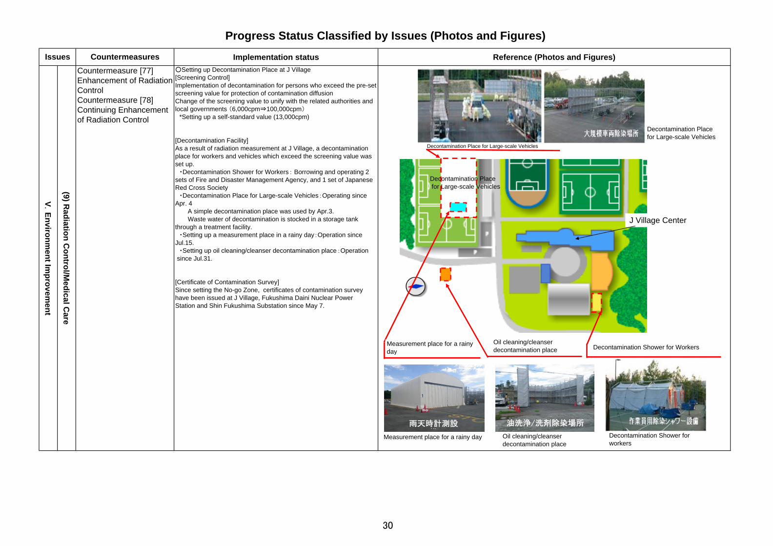
Issues CountermeasuresCountermeasure [77]Enhancement of RadiationControlCountermeasure [78]Continuing Enhancementof Radiation Control
V. Environm
ent Improvem
ent
○Setting up Decontamination Place at J Village[Screening Control]Implementation of decontamination for persons who exceed the pre-setscreening value for protection of contamination diffusionChange of the screening value to unify with the related authorities andlocal governments (6,000cpm⇒100,000cpm) *Setting up a self-standard value (13,000cpm)
[Decontamination Facility]As a result of radiation measurement at J Village, a decontaminationplace for workers and vehicles which exceed the screening value wasset up. ・Decontamination Shower for Workers: Borrowing and operating 2sets of Fire and Disaster Management Agency, and 1 set of JapaneseRed Cross Society ・Decontamination Place for Large-scale Vehicles:Operating sinceApr. 4 A simple decontamination place was used by Apr.3. Waste water of decontamination is stocked in a storage tankthrough a treatment facility. ・Setting up a measurement place in a rainy day:Operation sinceJul.15. ・Setting up oil cleaning/cleanser decontamination place:Operation since Jul.31.
[Certificate of Contamination Survey]Since setting the No-go Zone, certificates of contamination surveyhave been issued at J Village, Fukushima Daini Nuclear PowerStation and Shin Fukushima Substation since May 7.
Decontamination Shower for Workers
J Village Center
Decontamination Place for Large-scale Vehicles
Decontamination Place for Large-scale Vehicles
Decontamination Placefor Large-scale Vehicles
Decontamination Shower forworkers
油洗浄/洗剤除染場所雨天時計測設備
Measurement place for a rainyday
Oil cleaning/cleanserdecontamination place
Measurement place for a rainy day Oil cleaning/cleanserdecontamination place
30

Implementation Status Reference (Photos and Figures)
Progress Status Classified by Issues (Photos and Figures)Issues Countermeasures
Countermeasure [77]Enhancement of RadiationControlCountermeasure [78]Continuing Enhancementof Radiation Control
V. Environm
ent Improvem
ent
○Preparation of Measurement Infrastructure for Internal Radiation by Expansion of Whole Body Counter (WBC)
In order to implement evaluation of internal exposure for workers,etc., 13 WBCs are prepared with a building for WBC in J Village.
[Location]1. Hirono Football Stadium (next to the stadium building) (Training facility for rainy days)
2. Metropolitan Area
[Number of Unit]1. 13 sets:1 set (in-vehicle type borrowed from JAEA ①), 12 sets (stationary type)* 2. 1 set:1 set (in-vehicle type borrowed from JAEA②) * 4 sets transferred from 1F/2F, 7 sets newly purchased and 1 setborrowed from another company
[Operation Schedule][1. Hirono Football Stadium (next to the stadium building)] -By Aug.17 (actual achievement) Under operation: 1 set (in-vehicle type borrowed from JAEA①),and 5 sets (stationary type) -By the beginning of October Newly purchase of 6 sets (stationary type) and borrowing of 1 set (stationary type) borrowed from another company, and start operation[2. Metropolitan Area] Under operation: 1 set (in-vehicle type borrowed from JAEA)
Proper Treatment of Radioactive Waste[Liquid Waste (Decontamination Liquid Waste)]Decontamination liquid waste was collected in J Village and purifiedby a purification facilityThe purified liquid waste is planned to be used for decontaminationwater after confirmation of contamination density.* Installation and operation of the purification facility:Apr. 4-, Reuse:
Within August (planned)
[Solid Waste]Waste of protection cloths, etc. used in J Village and other screeningsites in Fukushima Prefecture, etc. are kept in J Village.The wastes were distinguished to combustible, fire-retardant and non-combustible type, and kept in special metal containers.
(9) Radiation C
ontrol/Medical C
are
7月25日から運用中
8月12日から運用中
8月 6日から運用中
10月上旬までに順次運用開始
他社借用⑬
⑫
⑪
⑩
⑨
⑧
新規購入
⑦
新規購入⑥
⑤
④ 1Fから据置型を移設
8月 5日から運用中③
2Fから据置型を移設7月13日から運用中②
車載型 JAEA借用7月11日から運用中①
ホールボディカウンタの運用開始時期
7月25日から運用中
8月12日から運用中
8月 6日から運用中
10月上旬までに順次運用開始
他社借用⑬
⑫
⑪
⑩
⑨
⑧
新規購入
⑦
新規購入⑥
⑤
④ 1Fから据置型を移設
8月 5日から運用中③
2Fから据置型を移設7月13日から運用中②
車載型 JAEA借用7月11日から運用中①
ホールボディカウンタの運用開始時期
①車載型WBC建屋②据置型WBC建屋
J Village Center Building
Hirono Football
①
②
⑥
⑫
⑦
⑧
⑨
⑩
⑪
⑬
J Village Center
PurificationFacility
Decontamination Place for Large-scale Vehicles
Purification Facility Separation andStorage of Solid Waste
Operation Schedule of Whole Body Counters
Area of Separation andStorage of Solid Waste
Will be operated by theBeginning of October
Newly purchased
Borrowed from another company
Operation since Jul. 11
Operation since Jul. 13
In-vehicle type borrowed from JAEA
Stationary type transferred from 2F
Newly purchased
Stationary typetransferred from 1F
Operation since Aug. 5
Operation since Aug. 6
Operation since Aug. 12
Operation since Jul. 25
⑤
④
③
31

Implementation status Reference (Photos and Figures)
Progress Status Classified by Issues (Photos and Figures)Issues Countermeasures
Countermeasure [77]Enhancement of radiationcontrolCountermeasure [78]Continuing enhancementof radiation control
(9) Radiation control / M
edical care
V. Environment Im
provement
- Reinforced radiation controlling Pocket dosimeters had been lentthrough signing in a recording book ofentering the data manually intodatabase, but worker identificationcards with barcodes were providedsince Jun. 8 so that it becomespossible to enter the data directly intothe database with barcode readers. From Aug. 16, we are planning tointroduce a system which can outputradiation exposure data on receiptsand at the same time automaticallyacquire individual radiation exposuredata of workers. (Worker identification card system is inoperation and personal radiationexposure data have been automaticallyacquired at Main Anti-EarthquakeBuilding of Fukushima Daiichi, but notin operation at J-Village due to lack ofequipment.)
① Lending Alarm Pocket Dosimeter and signing in arecording book
- lending pocket dosimeter andsigning the names, time, etc. ina recording book to managepersonal in-and-out.
- Measurement with pocketdosimeter for each time
③ Entering measurement results in the book and PC
- Entering data of time, radiationexposure, etc. in the book or PCwhen leaving the area
Aftermath of the Earthquake (previously)
Measure personalradiation dose
Control workers in-and-out of the site
- Lending pocket dosimeter- Record manual data entry (until Apr. 13) →Barcodes (from Apr. 14)
Main Anti-Earthquake Building
Working Area
J-Village
- Lending pocket dosimeter- Record: manual data entry→Barcodes (from Jun. 8)- Notification of radiationexposure data:→Receipts (from Aug. 16)
Measure personalradiation dose
Control workers in-and-out
After improvement (from June)
② Working, carrying pocket dosimeter and measuring
32

Implementation Status Reference (Photos and Figures)
・Preventives against heat stroke Cool vest Mask with blower Cool scarf
Progress Status Classified by Issues(Photos and Figures)
Issues CountermeasuresCountermeasure [79]Improvement of medicalsystemCountermeasure [80]Continuing improvementof medical system
We newly introduced mental supportfor workers, which is a system toimplement interviews, etc. once ortwice a month by specialists fromNational Defense Medical College, inJuly.In addition, based on the medicalexaminations implemented over"Workers engaged in emergency tasksfor more than one month" according tothe instruction by Fukushima LabourBureau, we implemented healthchecks targeting TEPCO employeesfor the first step from Aug.1 for 10days.The numbers of patients at theemergency medical treatment facilityin Unit 5/6, which opened on Jul. 1,was 26 in total (out of which thenumber of heat stroke was 12) as ofAug. 8. The number of patients wasrather small because of thoroughpreventive measures taken andadvanced notification about heatstroke. The facility was also utilized foremergency medical treatment forworkers who fell from power poles.
(9)Radiation control/m
edical care
V. Environment Im
provement
Consultation room inMain Anti-Earthquake
Building
Cool vest Cool scarfMask with blower
Emergency medicaltreatment facility in
Unit5/6
Example :wearing Cool
scarf
Example :Ice pack for neck
Ice pack for neck*Source: vendor catalogue. Some are different from the real ones.
33
Implementation Status Reference (Photos and Figures)
Progress Status Classified by Issues(Photos and Figures)
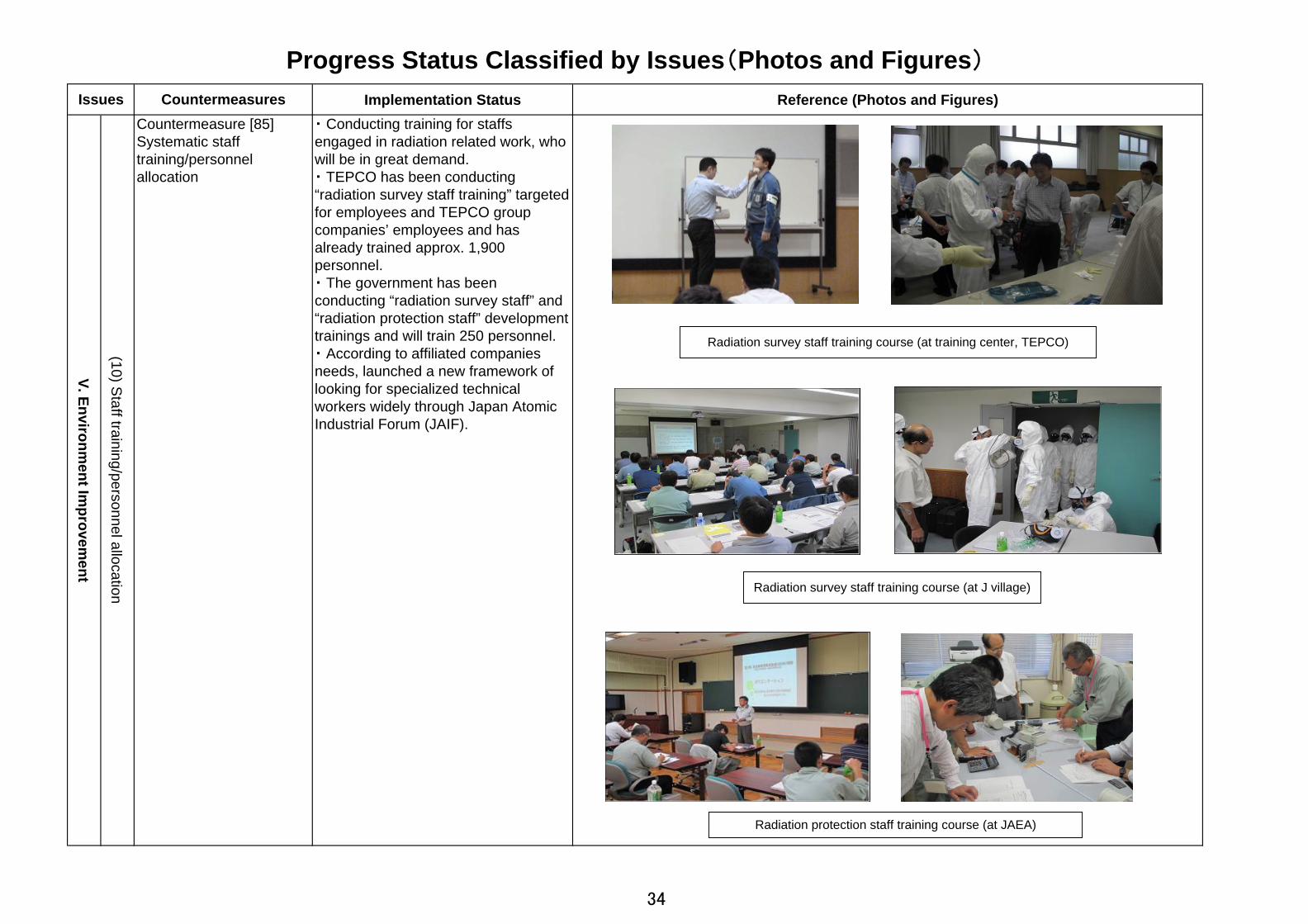
Issues CountermeasuresCountermeasure [85]Systematic stafftraining/personnelallocation
・ Conducting training for staffsengaged in radiation related work, whowill be in great demand.・ TEPCO has been conducting“radiation survey staff training” targetedfor employees and TEPCO groupcompanies’ employees and hasalready trained approx. 1,900personnel.・ The government has beenconducting “radiation survey staff” and“radiation protection staff” developmenttrainings and will train 250 personnel.・ According to affiliated companiesneeds, launched a new framework oflooking for specialized technicalworkers widely through Japan AtomicIndustrial Forum (JAIF).
(10) Staff training/personnel allocation
V. Environment Im
provement
Radiation survey staff training course (at J village)
Radiation protection staff training course (at JAEA)
Radiation survey staff training course (at training center, TEPCO)
34