progress towards a metrological fiber wide-area network 2014-11-21 · progress towards a...
TRANSCRIPT
12/11/2014 1
Progress towards a metrological fiber wide-area network
A. Amy-Klein, P.E. Pottie Laboratoire de Physique des Lasers, Université Paris 13, CNRS, France
LNE-SYRTE, Observatoire de Paris, UPMC, CNRS, France

12/11/2014 2
Optical link team
Anthony Bercy Fabio Stefani
Olivier Lopez Anne Amy-Klein Christian Chardonnet Nicolas Quintin Nicola Chiodo Fabrice Wiotte
Laboratoire de Physique des Lasers Paul-Eric Pottie
Giorgio Santarelli* Won Kyu Lee** Amal Kanj Daniele Rovera Joseph Achkar * now at LP2N, Bordeaux **visitor from Kriss, Korea
LNE-SYRTE
Emilie Camisard Thierry Bono Laurent Gydé
Renater

Outline
I. Ultrastable fiber link – Principle – Internet fiber link – Cascaded link
II. Current developments – 1100-km cascaded link – Multi-user dissemination – Time transfer
12/11/2014 3

The challenge of ultrastable frequency dissemination
12/11/2014 4
Lab B
Time-frequency metrology •Clocks comparison, evaluation, optimisation
High-precision physics •Fundamental constants measurement (h/m, kB…) and variation test (α ou me/mp) •Test of relativity, geodesy •Synchronisation in astrophysics and particle physics • Laser stabilisation, high-resolution spectroscopy
Lab A
Atomic clocks
Stability(1s) 10-15-10-16
Accuracy 10-17-10-18
Reference frequency

Means of ultrastable frequency dissemination
12/11/2014 5
Lab B
Time-frequency metrology
High-precision physics
Lab A
Atomic clocks
Stability(1s) 10-15-10-16
Accuracy 10-17-10-18
Optical Fiber Link
Satellite Link 10-11(1s)-10-15(1d)
Rapid development since 10 years 10-14(1s)-<10-18(1d)
Transportable clock (FOM)
10-13(1s)-4x10-16(1d)

Simplified scheme of an optical fiber link
12/11/2014 6
Fluctuation of the propagation delay « Round-trip » method for noise compensation Propagation delay limits noise rejection bandwidth and amplitude
Demonstration with 2 parallel fibers or one loop fiber : two ends at the same place
LOCAL END
Accumulated Phase noise
Ultra-stable 1.542 µm laser
Noise correction
REMOTE END
ΦP 2(ΦC + ΦP) = 0
Link instability measurement
Atomic optical clocks
ΦC
ΦC +ΦP=0
Lab A Lab B

Strategy for a continental network
12/11/2014 7
Use public telecommunication fiber networks – Dense Wavelength-Division Multiplexing (DWDM) Digital data Ultra-stable frequency signal -> Dark channel instead of dark fiber !
Collaboration with RENATER : the French National Research and Education Network
OADM (optical add drop multiplexer) to add and extract signal – Commercial components (100 GHz filters) – Losses < 1dB, Isolation > 25 dB – Bidirectional OADM
data ultra-stable fy
→ Simultaneous transmission on ≠ lambdas (or channels)
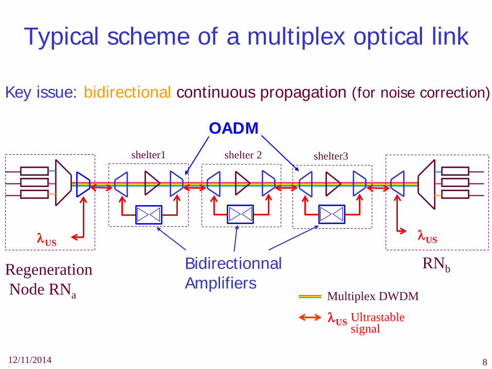
Typical scheme of a multiplex optical link
12/11/2014 8
Key issue: bidirectional continuous propagation (for noise correction)
shelter1 shelter 2 shelter3
RNb
Multiplex DWDM
Ultrastable signal
λUS
Regeneration Node RNa
Bidirectionnal Amplifiers
OADM
λUS λUS

OADM and EDFA modules
in Condé
12/11/2014 9

12/11/2014 10
Multi-segments approach : – Link is divided into a few segments, depending on noise and losses → shorter propagation delay → larger bandwidth and better noise rejection
Repeater stations are needed – Repeater station N : send back signal to station N-1, amplify and filter,
correct the noise of next link N
Long distance optical link
Local end
Remote end
Repeater Station
N
Repeater Station N+1
Repeater Station
N-1
Link N
Link N+1

12/11/2014 11
Optical regeneration station
Laser Lock
FM FM
Laser current + temp. reg.
Temperature control
link lock N+1
1-2 mW 1-2 mW
<1mW
Polar CTRL
. FM
Link N Lock
FM
Local Link
Local Link
Station N Station N-1
Link N
Local Laser
Link N+1
• Automated with remote control (IP) • Polarization control • No stable RF clock required
•Noise clean-up (optical regeneration) •Retrace back signal to station N-1 •Correct Link N+1 noise
O. Lopez et al. Optics Express (2012)

Rgeneration station
12/11/2014 12
Dimensions : 4U 19’’ x 350mm Power < 100 W

12/11/2014 13
Ongoing development: metrological fiber network in France and Europe
In France Refimeve+ Remif (IdF) PI: C. Chardonnet
In Europe : NEAT-FT Funded 2012 PI: H. Schnatz (PTB) See previous talk
Bordeaux
Toulouse
Marseille
Nice
Strasbourg
Lille
Besançon Nançay
Paris Reims
Germany / PTB
Italy/ Inrim
UK / NPL
Grenoble

12/11/2014 14
Villetaneuse Reims
Strasbourg
4 5
0 2
Nancy
4 cascaded links with 2 end stations and 3 regeneration stations US signal: 1542,14 nm (ITU 44) /Data: 1542.94 + 1543.73 nm
(ITU 43 & 42) 32 OADMs + 12 bidirectional EDFAs
Cascaded 1100-km LPL-Nancy-LPL link
0 1 3
2 4
2 5

12/11/2014 15
End-to-end phase variation
0 1 2 3 4 5 6 7 8 9 10 11 12 13 14-5
0
5
10
15
20
Dela
y va
riatio
n, fe
mto
seco
nds
Time, Hours
LPL-Nancy-LPL compensated link - 1100-km
8 points removed Λ-counter 1-s gate time

12/11/2014 16
End-to-end stability LPL-Nancy-LPL compensated link - 1100-km
100 101 102 103 10410-19
10-18
10-17
10-16
10-15
10-14
Alla
n de
viatio
n σ y(τ
)
Averaging time, τ, s
Λ-counter Modified ADEV
Unstabilized LPL-Reims-LPL link
Ushijima et al Sr clock

Multi-user dissemination
Several labs spread in the same metropolitan area – For instance Paris
Multi user Network architecture – Point-to-point distribution is fibers consuming – In-line extraction enables flexible distribution – First proposed by G. Grosche (PTB, Germany), in 2010
12/11/2014 17
Lab A Lab B
LabD
Main link
LabC Secondary link
Extraction

Extraction stability on a 86+6 km urban link
12/11/2014 18
100 101 102 103 104 105
10-19
10-18
10-17
10-16
10-15
10-14 End-to-End Free Π
End-to-Extraction Compensated Π
End-to-End Compensated Π
Averaging time τ (s)
Alla
n de
viat
ion
σ y(τ
)
A. Bercy et al. JOSA B (2013)
Full bandwidth - Π-counter

Two-way time transfer through optical fiber
Two-way time transfer demonstrated simultaneously with frequency transfer on the 540-km public fiber link
The time signal is encoded using pseudo random noise modulation with Satre modems used for satellite time transfer
12/11/2014 19
Clock A Clock B
At Bt
Epochs tB - tA

Time delay measurement on 540-km fiber link
12/11/2014 20
0 4 8 12 16-100
-50
0
50
100
time [d]
Tim
e diff
eren
ce [p
s]
-6
-4
-2
0
2
4
6One way delay [ns]

12/11/2014 21
Time transfer accuracy and stability
Delay calibration < 50 ps – Sensitivity to link length, power, polarisation,
dispersion….
Fiber time transfer
GPS carrier-phase
Two-way satellite time & fy transfer
Accuracy ~200 ps ~300ps ~500ps
Stability (1 day) ~20 ps ~100ps ~50 ps
O. Lopez et al. Applied Physics B (2013)

11/12/2014 22
Summary and outlook
Optical links are now mature – Paris-Nancy-Paris 1100 km non-dedicated fibers – Braunschweig-Munchen-Braunschweig 1840 km dedicated fibers – In progress : in-line extraction, fiber network development
Perspective – Remote clock comparison, search for fundamental constants
variation, relativistic geodesy... – Fundamental limits / Sagnac effect – Test of satellite links (ACES MW, Two-Way or advanced GPS) – Applications to high-resolution spectroscopy…

12/11/2014 23

100 101 102 103 10410-20
10-19
10-18
10-17
10-16
10-15
10-14
Alla
n de
viatio
n σ y(τ
)
Averaging time, τ, s12/11/2014 24
LPL-Reims-LPL 540-km stability
Π-counter (full BW) Overlapping ADEV
Unstabilized link
Λ-counter Modified ADEV
Ushijima et al Sr clock
2 spans
1 span
1 span

12/11/2014 25
6 points removed
540-km end-to-end propagation delay
1 span LPL-Reims-LPL

12/11/2014 26
LPL-REIMS-LPL 540km, 16 OADMs, 6 EDFAs Att. ~60dB, S/N ~80-90 dB
2x 100km spools 2 OADMs, 1 EDFA Att. ~30dB
Simulation of Paris-Strasbourg-Paris 740km
Station 0
Station 2 LPL
NR Reims Counter
Station 1

Time transfer reproducibility
Systematics effects can be controlled to less than 50 ps – Delay calibration < 50 ps, power sensitivity< 15 ps/dB, fiber
chromatic dispersion < 25 ps, polarisation mode dispersion < 50 ps But scarce phase jumps of ~100 ps Room for a lot of improvment !
12/11/2014 27
Fiber time transfer
GPS carrier-phase
Two-way satellite time & fy transfer
T2L2 Time Tr. by Laser Link
Accuracy ~250 ps <3 ns 1 ns ~300 ps
Stability (1 day) ~20 ps 0.1 ns 40 ps
<10 ps (10-100 s et 1-10 d)

State of the art
12/11/2014 28
• JILA-NIST (USA) optical carrier phase and frequency comb transfer
• SYRTE - LPL (Fr) 1100 km optical carrier phase
• PTB-MPQ-Hannover (Germany) 1840 km optical carrier phase
• NICT, NMIJ, UT (Japan) 120-km optical carrier phase
• JPL (USA) microwave optical link
• NPL (UK) frequency comb, optical carrier phase
• NIM, SIOM Shangai (China) microwave optical link
• INRIM, LENS (Italy) 670-km optical carrier phase
• UWA,NMI (Australia) optical carrier phase & microwave
• AGH (Poland) microwave time transfer
• ….

12/11/2014 29
Paris Metropolitan Area Network
8 research labs
Paris Area
APC
LKB
SYRTE
Node TH2
POP Renater
Supplier
User
Orsay Area
LPL
LPMAA
Main Link
Secondary Link
In-line Extraction
National Network
Eiffel Tower
2 km 1 mile
Node I1

→ shorter delay → larger BW&better noise rejection → better signal-to-noise
Cascaded segments for long range links
λUS
LocalLaser
FMAOM1
RF Local Oscillator
PLL1
Optical RegenerationStation 40 MHz
AOM2
PLL2
FM
75 MHz
150 MHz
35 MHz
LocalLaser
FMAOM1
RF Local Oscillator
PLL1
Optical RegenerationStation 40 MHz
AOM2
PLL2
FM
75 MHz
150 MHz
35 MHz
LocalLaser
FMAOM1
RF Local Oscillator
PLL1
Optical RegenerationStation 40 MHz
AOM2
PLL2
FM
75 MHz
150 MHz
35 MHz
Multi-segments approach : Segment lenght, tradeoff noise&attenuation
λUS

12/11/2014
Laser
PD
PC
Faraday mirror
AOM
RF oscillator
Filter
74 MHz
-37 MHz
ν0+113 PD Filter PLL
152 MHz
AOM 39 MHz ν0+39 ν0
ν0+152
Faraday mirror
Ultrastable Laser
PLL
ν0+76
RF oscillator
Link stability measurement
Local Remote
Optical link set-up
Autonomous lock (microcontroller), no stable RF clock at remote end, optical regeneration (PLL), automatic polarisation controller,
31