progressive fracture of fiber composite thin shell ... · pdf fileprogressive fracture of...
TRANSCRIPT

/
NASA Technical Memorandum 107234
Progressive Fracture of Fiber CompositeThin Shell Structures Under InternalPressure and Axial Loads
Pascal K. Gotsis and Christos C. Chamis
Lewis Research Center
Cleveland, Ohio
Levon Minnetyan
Clarkson University
Potsdam, New York
September 1996
National Aeronautics and
Space Administration
https://ntrs.nasa.gov/search.jsp?R=19970001596 2018-04-16T23:10:00+00:00Z

Trade names or manufacturers' names are used in this report for identification
only. This usage does not constitute an official endorsement, either expressed
or implied, by the National Aeronautics and Space Administration.
PROGRESSIVE FRACTURE OF FIBER COMPOSITE THIN SHELL
STRUCTURES UNDER INTERNAL PRESSURE AND AXIAL LOADS
Pascal K. Gotsis and Christos C. Chamis
National Aeronautics and Space Administration
Lewis Research Center, Cleveland, Ohio 44135
and
Levon Minnetyan
Clarkson University
Potsdam, New York 13699-5710
SUMMARY
Graphite/epoxy composite thin shell structures were simulated to investigate damage and fracture progression
due to internal pressure and axial loading. Defective and defect-free structures (thin cylinders) were examined. The
three laminates examined had fiber orientations of [90/0/+0] s, where 0 is 45 °, 60 °, and 75 °. CODSTRAN, an inte-grated computer code that scales up constituent level properties to the structural level and accounts for all possible
failure modes, was used to simulate composite degradation under loading. Damage initiation, growth, accumulation,
and propagation to fracture were included in the simulation. Burst pressures for defective and defect-free shells were
compared to evaluate damage tolerance.The results showed that damage initiation began with matrix failure whereas damage and/or fracture progres-
sion occurred as a result of additional matrix failure and fiber fracture. In both thin cylinder cases examined (defec-
tive and defect-free), the optimum layup configuration was [90/0/+60] s because it had the best damage tolerance
with respect to the burst pressure.
INTRODUCTION
Graphite/epoxy composite shell structures are used in various structural components such as aircraft fuselages,
jet engine cowls, pressure vessels, and rocket motor cases. In these applications, it is important to achieve low
weight, high strength, stiffness, and safety when composite shells are required to withstand significant internal pres-sures. This report discusses thin cylindrical shells subjected to internal pressure. Damage initiation, growth, accumu-
lation, and propagation to fracture were simulated for three cases.
For a rational design, it is necessary to quantify the defect and damage tolerance of a candidate structure.
Assessing this tolerance requires the capability to simulate the progressive damage and fracture characteristics of
composite structures under loading. Critical components of a structure must remain safe but be able to function
under loading after experiencing some damage. Damage may be caused by an accident, a defect, or an unexpected
overloading. A structure's tolerance to damage is quantified by the residual strength (i.e., the additional load-
carrying ability after damage).
Another design consideration is the multiplicity of options such as fiber orientation patterns and constituent
material combinations, choices that result in a great number of parameters that may be varied for an optimal design.
Design considerations with regard to the progressive fracture of fiber composite structures require a priori
evaluation of damage initiation and fracture propagation mechanisms under expected loading and service environ-ments. Concerns for the safety and survivability of critical components require that the structural fracture resistance
under loading be quantified. The present approach bypasses traditional fracture mechanics to provide an alternative
evaluation method, conveying to the design engineer a detailed description of damage initiation, growth, accumula-
tion, and propagation that would occur in the ultimate fracture of a fiber composite structure. The results show in
detail the damage progression sequence and structural fracture resistance during different degradation stages.

Thelaminateconfigurationisasignificantdesignparameterwithregardtocompositedamagetolerance.Ingeneral,quasi-isotropiclaminateshavebetterdamagetolerance(ref.1).However,inmanycaseswhenthereisnodamage,aquasi-isotropiclaminatemaynotbethemostefficientwithregardtostructuralstrengthandperformance.Arationaldesignprocessrequiresthatthestructuraldamagetoleranceforacandidatedesignbequantifiedbecausedamageinitiationandprogressioncharacteristicsaremuchmorecomplexforlaminatedfibercompositesthantheyareforhomogenousmaterials.Thestructuralfractureprocessofalaminatedfibercompositedependsonmanyparameters:laminateconfiguration,fibervolumeratio,constituentstiffness,strength,andhygrothermalpropertiesandthefabricationprocess.
Recentdevelopmentsincomputationalsimulationhavemadeit possibletoevaluateprogressivedamageandfractureincompositestructuresbyassessingthedamageinitiationandpropagationloads.Takenintoaccountaretheinfluenceof localdefectsorflaws,through-the-thicknesscracks,andtheeffectsofthefabricationprocessintermsofresidualstresses.Thisreportdemonstratesthatcomputationalsimulation,withtheuseofestablished mate-
rial modeling and finite element modules, adequately tracks the damage growth and subsequent propagation to frac-
ture of fiber composite pressurized shells. The present cylindrical shell simulations constitute an extension of the
work reported in reference 1 in which the defect tolerance characteristics of cross-ply and quasi-isotropic laminates
were investigated. The current study examines the effects of angle ply orientation on damage tolerance characteris-
tics and structural fracture modes. The CODSTRAN (COmposite Durability STRuctural ANalysis) computer code
was used to simulate the damage progression in a variety of composite structures: stiffened, adhesively bonded com-
posite structures (ref. 2), adhesively bonded concentric composite cylinders (ref. 3), damage progression in bolted
composite structures (ref. 4), progressive damage and fracture of adhesively bonded pipe joints (ref. 5), damage
tolerance of composite pressurized shells (ref. 6), progressive fracture of fiber composite builtup structures (ref. 7),
and progressive fracture of composite subjected to simulated Iosipescu shear testing (ref. 8).
This report describes the application of computational simulation to defect-free and damaged composite cylin-
drical shell specimens, taking into account damage initiation and/or propagation mechanisms. The purpose was to
identify the salient material and structural parameters for a design with damage tolerance considerations.
CODSTRAN METHODOLOGY
CODSTRAN is an integrated computer code in which three modules are coupled: composite mechanics
(ICAN), finite element analysis (MHOST), and damage progression modeling. ICAN (Integrated Composite Ana-
lyzer) is a composite mechanics computer code (ref. 9) that provides the constituent (fiber and matrix) material
properties from an available data bank and computes the ply properties and the composite properties (effective prop-
erties) of the laminate in a hygrothermal environment. The code is based on the theory of the micromechanics of
composites and the classical laminate theory. ICAN can compute ply stresses by using known stress resultants(force per laminate thickness, where force can be a bending, a twisting, or a concentrated load). In ICAN, two fail-
ure criteria were established for the detection of ply failures: (1) the maximum stress criterion in which individual
ply failure modes are assessed by ICAN using failure criteria associated with the negative and positive limits of the
six ply stress components in the material directions 1 to 3 (fig. 1):
S,11c < Oel 1 < SlllT (1)
St22C < (Yt22 < S_22T (2)
S_33C < Or33 < Se33T (3)
S_12(_ ) < (ltl 2 < S,12(+) (4)
5t23(-) < _23 < 5t23(+) (5)
Sg13(-) < (Y*I3< Sgl3(+) (6)

where Sfijo t represents the ply stress limit (ply strength) in which the ij subscript indicates the stress component andthe ct subscript indicates the sense as tension and/or compression for normal stresses and as _+for shear stress limits
on the ply; t_ is the ply stress. The ICAN composite mechanics module computes Sfijc t stress limits. (2) The modi-fied distortion energy (MDE) criterion takes into account combined stresses and is expressed as
2 2 la .l_((Y_I2S 121
F=I-I_ Sg-ff_la) _.Sg22[_ ) -Kg12 Sell a Sg22_ [,,Sgl2S ) J
(7)
where _ and [3 indicate tensile or compressive stress, S O 1_ is the ply longitudinal strength in tension or compres-
sion, 5_22e t is the transverse strength in tension or compression, and
(1 + 4Vg12 - VeI3)E_22 + (1 - Vg23)Egl 1Kgl2 = (8)
[EellE,22(2 + Vgl2 + vg13)(2 + Vg21 + Vg23)] 1/12
The type of failure is assessed by comparing the magnitudes of the squared terms in equation (7). Depending on
the dominant term in the MDE failure criterion, fiber failure or matrix failure is assigned. If the first squared term in
equation (7) that corresponds to ply longitudinal tensile or compressive failure is dominant, fiber failure is assigned.
On the other hand, if one of the other squared terms corresponding to ply transverse tensile or compressive failure or
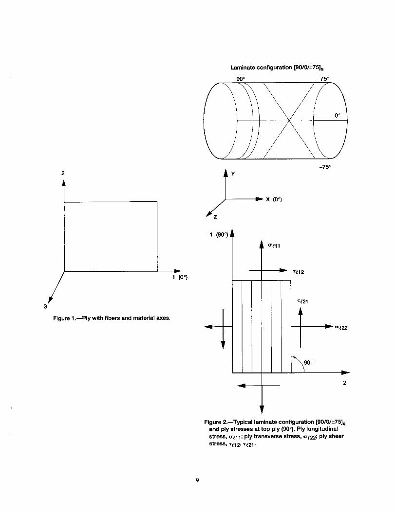
to ply shear failure is dominant, matrix failure is assigned. For example, a laminate with configuration [90/0/+75] s
has ply stresses at the top ply (90 °) and is shown in figure 2. In ICAN, the described failure modes of the plies arefailure due to fiber fracture in tension or in compression; damage due to matrix fracture in tension or in compres-
sion; and damage due to intralaminar shear fracture.
MHOST is a finite element computer code (ref. 10) used to solve structural analysis problems. The code can
perform linear or nonlinear static and dynamic analyses. MHOST has a library containing a variety of elements,
among which is the four-node shell element used for the present work. (This element is similar to element 75 in theMARC structural analysis finite element code.) By supplying the boundary conditions, the type of analysis desired,
the applied loads, and the laminate properties (using ICAN), MHOST performs the structural analysis. In addition,
MHOST provides the computed stress resultants to the ICAN code, which then computes the developed ply stresses
for each ply and checks for ply failure.
The damage progression module monitors composite degradation for the entire structure and relies on ICAN for
composite micromechanics, macromechanics, and laminate analysis. In this module, the overall evaluation of the
composite structural durability is conducted.
The CODSTRAN simulation cycle is shown in figure 3. Proceeding clockwise along the left side, one sees the
constituent material properties (fiber and matrix) provided by ICAN's data base, the ply properties computed fromthe micromechanics theory, and the laminate properties computed from the laminate theory. These properties in
conjunction with the finite element mesh, the loads, and the boundary conditions are incorporated in MHOST, which
performs the structural analysis and provides the computed stress resultants to ICAN (right side of the figure). ICAN
uses the laminate theory to compute the ply stresses and to check for ply failure.
The nonlinear structural analysis in the MHOST code is performed in conjunction with an incremental load
algorithm. The load is increased in small increments (equilibrium positions). In each position, a number of iterations
(incremental damages) is performed (fig. 4) and the structure is checked for ply failure. If damage is detected, the
model is automatically updated with a new finite element mesh and new laminate properties; then another finite
element analysis is performed and the iterations continue until no further damage occurs (equilibrium position). At
this point, the load is increased and the above procedure repeated until the final failure of the structure. The damage
progression, fracture, and collapse of the structure are monitored during this procedure.The CODSTRAN code is written in FORTRAN 77 computer language for UNIX operating systems at the
NASA Lewis Research Center.

THINSHELLSTRUCTURES
Damageandprogressivefracturewereinvestigatedforinternallypressurizedgraphite/epoxylaminatedcompos-itethincylindricalshells.Theshellstructuresconsistedofeight0.136-mm(0.00535-in.)pliesresultinginacompos-iteshellthicknessof 1.088mm(0.0428in.).Threelaminateconfigurationsof [90/0/+-0]swereconsidered:0 = 45 °,
60 °, and 75 °. The 90 ° plies were in the hoop/circumferential direction of the shells and the 0 ° plies were in the axial
direction. Fiber orientations in the +45 °, +60 °, and +75 ° (fig. 2) angle plies were given with reference to the axialdirections. The geometry of the thin cylindrical shells was identical (inside diameter, 305 mm or 12.0 in.; length,
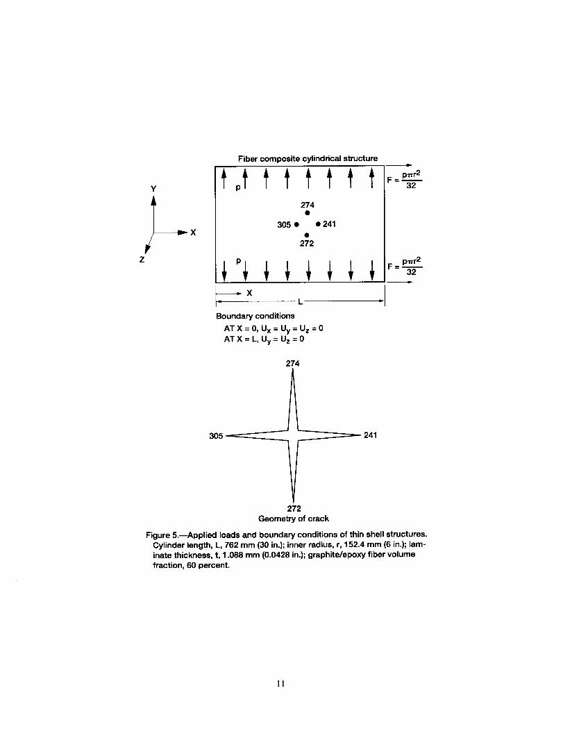
762 mm or 30 in.). The closed-end cylindrical pressure vessel was simulated by applying a uniformly distributed
axial tension so that the generalized axial stresses in the shell wall were half those developed in the hoop direction
(fig. 5). The composite shells were subjected to a monotonically increasing internal hydrostatic pressure until they
burst. All laminate configurations, defect-free shells and those with through-the-thickness defects, were examined
(fig. 5). Defects were modeled at a node located at the half-length of the shell. Each finite element model contained544 nodes and 512 uniformly sized rectangular elements (fig. 6). Damage initiation, growth, fracture progression,
and global structural fracture stages were investigated in each case. For both defective and defect-free shells, dam-
age initiation was by matrix cracking due to transverse tensile stresses in the 0° phes. For the defect-free shells, fiber
fractures did not occur until just before the structural fracture pressure was reached. The fiber volume ratio was 60
percent and the void volume ratio was 2 percent of the total volume of the structure. The residual stresses due to the
processing were taken into account. The cure temperature was 177 °C (350 °F); the pressurization/use temperature
was 21 °C (70 °F), the moisture content was zero. The fiber and matrix properties were
obtained from a CODSTRAN data bank of composite constituent material properties. The corresponding graphite
fibers (AS-4) and epoxy matrix (high-modulus, high-strength (HMHS)) properties are given in tables I and II,
respectively, and the AS-4/HMHS ply strength is given in table III. Computed results up to global fracture are pre-
sented for defect-free shells and those with through-the-thickness defects.
Defect-Free Structures
Simulations were conducted of defect-free pressurized shells that had three laminate configurations of
[90/0/+0] s for which the ply layups were 0 = 45 °, 60 °, and 75 °. The results are summarized as follows:
The CODSTRAN simulation of [90/0/+45] s indicated a damage initiation pressure of 0.799 MPa (116 psi).Initial damage occurred near the closed ends of the shell and took the form of matrix cracking in selected plies. The
damage progressed from cracking in the outermost 0° ply to the 45 ° ply immediately adjacent, to the innermost
0° ply, and then to the 90 ° ply on the interior surface. After damage initiation, all plies gradually sustained matrix
cracking as the pressure was increased to 0.837 MPa (121 psi). After this stage, the pressure was significantlyincreased without activating additional damage modes. The cylindrical shell burst when the 90 ° hoop plies experi-
enced fiber fractures at a simulated burst pressure of 4.80 MPa (0.696 ksi).
The CODSTRAN simulation of the [90/0/+60] s configuration revealed that when the orientations of angle plieswere changed to +60 °, the damage initiation pressure was increased to 0.965 MPa (140 psi). Similar to the case of
_+45° angle plies, initial damage took the form of matrix cracking in selected plies. At first, the outermost 0 ° ply
(ply 2) developed matrix cracking due to ply transverse tensile stresses; the degradation of ply 2 was followed by
that of ply 3 (the 60 ° ply immediately adjacent to ply 2). Subsequently, ply 7 (the innermost 0 ° ply) and ply 8 (the
90 ° ply on the interior surface) developed matrix cracks. After damage initiation, all plies gradually sustained matrix
cracking as the pressure remained virtually constant. After this initial damage growth stage, the pressure increased
considerably without activating additional significant damage modes. The cylindrical shell burst when ply 1 (the
outermost 90" hoop ply) experienced fiber fractures that resulted in a rapid propagation of damage to structural frac-
ture. The simulated burst pressure was 9.42 MPa (1.366 ksi).
The computational simulation of the [90/0/-+75] s configuration indicated a damage initiation pressure of1.062 MPa (154 psi), which was the highest pressure of the three defect-free shells investigated. Damage initiation
was by matrix cracking due to ply transverse tensile stresses in ply 2 (the outermost 0 ° ply). Immediately after
matrix cracking occurred in ply 2, plies 3, 7, and 8 experienced degradation. Failure modes were in-plane shear in
ply 3, transverse tensile in ply 7, and transverse tensile and in-plane shear in ply 8. Damage growth in the other plies
occurred as the pressure was kept virtually constant. After the initial matrix degradation stage, the pressure was
increasedwithoutactivatingadditionaldamage modes. The cylindrical shell burst when ply 2 (the outermost 0° axial
ply) experienced fiber fractures that caused rapid damage propagation to the other plies and then structural fracture.The simulated burst pressure was 7.83 MPa (1.136 ksi). It is noteworthy that structural fracture was initiated by the
tensile failure of axial fibers in this case whereas in the previous two defect-free shells, structural fracture com-
menced by the fracturing of the hoop plies.
In general, overall structural damage may include individual ply damage and through-the-thickness fracture of
the composite laminate. CODSTRAN is able to simulate varied and complex composite damage mechanisms by an
evaluation of the individual ply failure modes and the associated degradation of laminate properties. The type of
damage growth and the sequence of damage progression depend on the composite structure, loading, material prop-
erties, and hygrothermal conditions. A scalar damage variable, derived from the total volume of the composite mate-
rial affected by the various damage mechanisms, is also evaluated as an indicator of the level of overall damage
induced by loading. This scalar damage variable is useful for assessing the overall degradation of a given structure
under a prescribed loading condition. The rate of increase in the overall damage during composite degradation maybe used as a measure of the structural propensity for fracture. Figure 7 presents a comparison of the overall damage
progression histories for the three defect-free cylindrical shells. Damage initiation pressures and progression patternsare similar. However, burst pressures are strongly influenced by the laminate configuration. The [90/0/-+60] s defect-
free laminate had the highest burst pressure. On the other hand, the [90/0/±75] s defect-free laminate had the highest
damage initiation pressure. The [90/0/+_45] s defect-free laminate had the lowest burst pressure as well as the lowest
damage initiation pressure.
Defective Structures
Three additional simulations were conducted on shells that were modeled to have a through-the-thickness defect
in the form of an existing 95-mm- (3.75-in.-) long thin axial slit superimposed on a 60-mm- (2.36-in.-) long circum-
ferential slit at the half-length of the shell (fig. 6). Including a circumferential as well as an axial slit allowed self-
similar crack propagation in the axial and circumferential directions. A summary of the computational simulation
results for the through-the-thickness defective thin shells follows:
For the [90/0/+45] s quasi-isotropic shell, damage initiation began by matrix cracking adjacent to the defect assoon as an initial pressure of 0.172 MPa (25 psi) was applied. However, damage growth remained localized adjacent
to the defect until a 0.745-MPa (108-psi) pressure was reached. After damage initiation, all plies gradually sustained
matrix cracking as the pressure was increased to 0.837 MPa (121 psi). The damage accumulation stage (by matrix
cracking) was similar to that of the defect-free shell. However, after the matrix cracking stage was completed, the
damage propagation to ultimate fracture was much more rapid than that of the defect-free shell. Damage propagation
by fiber fractures was concentrated near the defect. Through-the-thickness structural fracture progression occurred at
1.58 MPa (0.230 ksi), causing the cylindrical shell to burst. For the [90/0/_+45] s laminate, the axial crack orientationwas the more critical. Figure 8 shows the finite element model as the simulated defective shell burst.
Similar to the +45 quasi-isotropic defective shell, damage initiation in the [90/0/+_60] s shell began by matrixcracking adjacent to the defect as soon as the initial pressure of 0.172 MPa (25 psi) was applied. Initially, matrix
failures at the circumferential slit tips commenced by transverse tensile failures in ply 8, and matrix failures in the
axial slit tips commenced by transverse tensile failures in ply 7. As in the 45 ° angle plies, damage growth remained
localized adjacent to the defect until a 0.911-MPa (132-psi) pressure was reached. Substantial matrix degradations
away from the defect also occurred as the pressure was gradually increased from 0.911 to 1.020 MPa (132 to
148 psi). Fracture progression began at 1.765 MPa (256 psi) by the extension of the axial slit. As the pressure in-creased, the circumferential slit also became extended. Structural fracture occurred at 1.90 MPa (0.275 ksi), causing
the cylindrical shell to burst.
Damage initiation in the [90/0/+75] s shell began by matrix cracking adjacent to the defect as soon as the initial
pressure of 0.172 MPa (25 psi) was applied. Matrix failures at the circumferential slit tips were initiated by trans-verse tensile failures in ply 8. As in the 45 ° angle plies, damage growth remained localized adjacent to the defect.
The ultimate structural fracture stage began as the pressure was increased to 0.621 MPa (90 psi). Fracture progres-
sion was mainly by extension of the circumferential slit. Structural fracture occurred at 0.72 MPa (0.104 ksi), caus-
ing the cylindrical shell to burst by a circumferential fracture.

Figure9comparestheoveralldamageprogressionhistoriesforthethreedefectivecylindricalshells.Damageinitiationpressuresandprogressionpatternsaresimilar.However,burstpressuresandstructuralfracturemodesarestronglyinfluencedbythelaminateconfiguration.The[90/0/-+60]slaminatehasthehighestburstpressure,asisthecaseforthedefect-freelaminates.Ontheotherhand,the[90/0/:t:75]sdefectivelaminatehasthelowestdamageini-tiationpressure,unlikethedefect-freeshells.The[90/0/_+45] s defective laminate has intermediate burst and damage
progression pressures. An examination of structural fracture modes indicates that for the [90/0/_+45] s laminate, burst-
ing occurs at the commencement of fracture propagation along the axial direction. For the [90/0/+60]s defectivelaminate, fracture also commences along the axial direction; however, a circumferential extension of the defect
occurs at the same pressure level. On the other hand, for the [90/0/__.75]s defective shell, fracture initiation and
progression occur mainly in the circumferential direction. The circumferential fracture mode of the [90/0/+75] slaminate is considerably less damage tolerant. Table IV summarizes the burst pressures for the defect-free and
defective shells. If damage tolerance is defined as the ratio of the defective to the defect-free burst pressures for each
laminate, the [90/0/+45] s laminate would have a damage tolerance ratio of 33 percent; the [90/0/+60]s laminate, a
ratio of 20 percent; and the [90/0/-+75] s laminate, a ratio of 9.2 percent for the assumed initial damage. However, if
all burst pressures had been normalized with respect to the burst pressure of the defect-free [90/0/+60]s laminate, the
damage tolerance ratio of the [90/0/-+45] s laminate would drop to 17 percent and that of the [90/0/+75]s laminate
would be reduced to 7.6 percent. These results indicate that the [90/0/+60] s laminate has the best damage tolerancefeatures in this application because of its well-balanced fiber reinforcement pattern.
Another perspective on damage progression characteristics may be obtained by quantifying the structural resis-
tance to damage propagation. The global damage energy release rate (DERR) is defined as the rate of work done by
external forces during structural degradation with respect to the damage produced. The DERR can be used to evalu-
ate structural resistance to damage propagation at different stages of loading. Figure 10 shows the DERR as a func-
tion of the applied pressure for the defective [90/0/_+60]s specimen. The DERR for damage initiation is relativelysmall, indicating a low resistance to damage initiation by matrix cracking. However, after the damage initiation
stage, the DERR steadily increases, which indicates a greater structural resistance to damage propagation during a
damage stabilization stage prior to global fracture. The maximum DERR level corresponds to the completion of the
matrix cracking stage prior to the occurrence of ply fiber fractures.
Figure 11 shows the DERR levels for the defective [90/0/+75]s shell, for which the very low levels during theinitial stages of damage progression indicate the lack of structural resistance to damage propagation and predict the
sensitivity of damage progression to variations in the constituent material properties.
CONCLUSIONS
The computer code CODSTRAN (COmposite Durability STRuctural ANalysis) was used to evaluate the dam-
age growth and propagation to fracture of cylindrical composite shells. The conclusions follow:
1. The CODSTRAN simulation demonstrates the progression of damage growth and subsequent propagation to
fracture for defect-free and through-the-thickness defective composite shells subjected to internal pressure.
2. Through-the-thickness defects have a significant effect on the structural fracture pressure for internally pres-
surized thin shells. However, the damage initiation stage begins at low load levels for all simulated laminate con-figurations.
3. The damage stability after a major accident can be evaluated to serve as an index of the structural damagetolerance.
4. Computational simulation, with the use of established composite mechanics and finite element modules, can
be utilized to predict the influence of existing defects, loading, constituent properties, and residual stresses on the
safety and durability of composite structures.
5. The demonstrated procedure is flexible and applicable to all types of constituent materials, structural geom-
etry, and loading. Hybrid composites and homogeneous materials as well as binary composites can be simulated.
6. The reduction in the ultimate pressure and the variation of the structural fracture mode are predictable withreference to the location and the size of the defect or the damage.
7. The procedure used herein demonstrated that fracture toughness parameters such as the structural fracture
pressure and damage progression characteristics are identifiable for fiber composite structures with defects.
REFERENCES
1. Gotsis,P.K.;Chamis,C.C.;andMinnetyan,L.:DefectToleranceofPressurizedFiberCompositeShellStruc-tures.Proceedingsofthe41stInternationalSAMPESymposiumandExhibition,vol.41,book1,1996,pp.450-461.
2. Gotsis,P.K.;Chamis,C.C.;andMinnetyan,L.:EffectofCombinedLoadsintheDurabilityofaStiffenedAdhesivelyBondedCompositeStructure.Proceedingsofthe36thAIAA/ASME/ASCE/AHS/ASCStruc-tures,StructuralDynamics,andMaterialsConference,AIAA-95-1283-CP,pp.1083-1092.
3. MinnetyanL.;andGotsis,P.K.:ProgressiveFractureinAdhesivelyBondedConcentricCylinders.Proceedingof the40thInternationalSAMPESymposiumandExhibition,vol.40,book1,1995,pp.849-860.
4. Chamis,C.C.;Gotsis,P.K.;andMinnetyan,L.:ProgressiveDamageandFractureofAdhesivelyBondedFiberCompositePipeJoints.EnergyWeekConferenceandExhibition,SymposiumonCompositeMaterialsDesignandAnalysis,bookV, legendV,1996,pp.401-408.
5. Chamis,C.C.;Gotsis,P.K.;andMinnetyan,L.:DamageProgressioninBoltedCompositeStructures.Proceed-ingsoftheUSAFStructuralIntegrityProgramConference,1995.Proceedingsinpublication.
6. Chamis,C.C.;Gotsis,P.K.;andMinnetyan,L.:DamageToleranceofCompositePressurizedShells.Proceed-ingsofthe37thAIAA/ASME/ASCE/AHS/ASCStructures,StructuralDynamics,andMaterialsConference,AIAA-96-1556-CP,part4,1996,pp.2112-2121.
7. Gotsis,P.K.;Chamis,C.C.;andMinnetyan,L.:ProgressiveFractureofFiberCompositeBuiltupStructures.NASATM-107231,1996.
8. Minnetyan,L.etal.:ProgressiveFractureofCompositeSubjectedtoIosipescuShearTesting.AcceptedforpublicationattheProceedingsforthe13thSymposiumonCompositeMaterial:TestingandDesign,May1996.
9. Murthy,P.L.N;Ginty,C.A.;andSanfeliz,J.G.:SecondGenerationIntegratedCompositeAnalyzer(ICAN)ComputerCode.NASATP-3290,1993.
10.Nakazawa,S.:MHOSTUser'sManual,version4.2,vol.1,NASACR-182235,1989.

TABLE I.--AS-4 GRAPHITE FIBER PROPERTIES
Number per end ............................................................................................................................................. 10 000Diameter, mm (in.) ......................................................................................................... 0.00762 (0.300x 10 -3)
Density, kg/m 3 (lb/in. 3) .......................................................................................................... 4.04x10 -7 (0.063)
Normal modulus, GPa (psi)Longitudinal ............................................................................................................................. 227 (32.90x 10⁶)
Transverse ................................................................................................................................. 13.7 (1.99x 10⁶)Poisson's ratio
v12 ......................................................................................................................................................................... 0.20
v23 ......................................................................................................................................................................... 0.25Shear modulus, GPa (psi)
Gt2 ................................................................................................................................................. 13.8 (2.00x l(Y')
G23 ................................................................................................................................................. 6.90 (1.00X 10 o)
Thermal expansion coefficient,/°C (/°F)
Longitudinal .................................................................................................................. 1.0 x 10 .4 (-0.55x 10 o)
Transverse ..................................................................................................................... 1.0× 10⁴ (-0.56x 10 -6)
Heat conductivity, J-m/hr/m2/oC (BTU-in./hr/in.2/°F)
Longitudinal .......................................................................................................................................... 43.4 (580)
Transverse ............................................................................................................................................... 4.34 (58)
Heat capacity, J/Kg/°C (BTU/Ib/°F) ............................................................................................. 712 (0.17)
Strength, MPa (ksi)
Tensile .................................................................................................................................................. 3723 (540)
Compressive ....................................................................................................................................... 3351 (486)
TABLE II.--HMHS EPOXY MATRIX PROPERTIES
Density, kg/m 3 (lb/in. 3 ) ........................................................................................... 3.40x 10 -7 (0.0457)
Normal modulus, GPa (ksi) .................................................................................................... 4.27 (629)
Poisson's ratio, v ...................................................................................................................................... 0.34
Coefficient of thermal expansion, /°C (/°F) ......................................................... 0.72 (0.4x 10 4)
Heat conductivity, J-m/hr/m2pC (Btu-in./hr/in.2/°F) .................................................. 930 (1.25)
Heat capacity, J/kg/°C (Btu/lb/°F) ..................................................................................... 738 (0.25)
Strength, MPa (ksi)Tensile ........................................................................................................................................ 84.8 (12.3)
Compressive ............................................................................................................................. 423 (61.3)
Shear ............................................................................................................................................ 148 (21.4)Allowable strain
Tensile ..................................................................................................................................................... 0.02
Compressive ......................................................................................................................................... 0.05Shear strain ........................................................................................................................................... 0.04
Torsional ................................................................................................................................................. 0.04
Void conductivity, J-m/hr/m2/oC (Btu-in./hr/in.2/°F) .............................................. 16.8 (0.225)
Glass transition temperature, °C (°F) ................................................................................. 216 (420)
TABLE IlL--PLY STRENGTH OF AS-4/HMHS
[Fiber direction, parallel to ply 1 material axis;
tension, T; compression, C; material axes of
ply, 1 to 3.]
Ply stress component
S¢IlT
Stuc
StnTS¢22c
8_12
S¢23
Strength
MPa ksi
1930.30 2801475.85 210
91.38 13228.27 33
65.57 9_5
59.98 8.7
TABLE IV.--BURST PRESSURES
Laminate
[90/0/+451,
19o/o&_ol+[90/0/+75]+
Shell structure
Defect free [ Defective|
Burst pressure
M Pa ksi M Pa ksi
4.8 0.696 1.58 0.230
9.42 1.366 1.90 .2755
7.83 1.135 .72 .104
Laminate configuration [90/0/_+75]s
90 ° 75 °
-75 °
"- (o)X o
/3
Figure 1 .BPly with fibers and material axes.
y
1 (0°)
1 (90 °)
i
ere11
y 1"£12
"re21
L v_ o-e2 2
2
Figure 2.--Typical laminate configuration [90/0/_75]s
and ply stresses at top ply (90°). Ply longitudinal
stress, _e11; ply transverse stress, ¢re22; ply shear
stress, 7_12, _t21.

To To
global globalstructural structural
analysis analysis
/ ,wL'_'_ _ X -_Y / _ \
/ __,"_ \ / ¢_,':_ \
//Laminat_ "_'_'---_f_/ _ Laminate\
/ _ Laminate _ / L aminate Jp
I / theory _ / theory •ICAN _ a_z-------:-.-----._
_ ./Composite I
Composite _ • " /
\ micromechanics _ %.P _h=:r_ymechan'cs/
theory _ pJ /\\ _ T /
\ /\ M /
Constituents Material propertie_, J
Upward _ p(_r, T, M) _/Top-down
integrated _--- ..../ traced or
or "synthesis" "decomposition"
Figure 3.---CODSTRAN progressive fracture simulation cycle.
_-- Incremental damage
//I Property degradation
- o!0Jlincrement / I
- ss/_, "_ (no additional increment
_damage) t
\ _ Equilibrium
Displacement
Figure 4._CODSTRAN load incrementation.
10
Y
Z
Fibercompositecylindricalstructure
tottttttt274
305 • • 241
272
_-_Xi,= L
Boundary conditions
ATX = 0, Ux = Uy= Uz =0
AT X = L, Uy = Uz = 0
274
241
=-=
. pwr 2
32
= P err232
_72
Geometry of crack
Figure 5.mApplied loads and boundary conditions of thin shell structures.
Cylinder length, L, 762 mm (30 in.); inner radius, r, 152.4 mm (6 in.); lam-inate thickness, t, 1.088 mm (0.0428 in.); graphite/epoxy fiber volume
fraction, 60 percent.
11

Z
Figure 6.--Finite element mesh of graphite/epoxy composite thin shell.
O
¢0Ec_
1.0 --
0.8 B
0.6--
0.4--
0.2--
0.0
\
I I I I I0.0 0.2 0.4 0.6 0.8 1.0
Normalized pressure (max. pressure, 9.42 MPa (1.37 ksi))
Figure 7.--Damage progression in defect-free graphite/epoxy thin cylindrical shells [90/O/_+O]s.
12

\Z
Figure 8.--Burst of defective shell [9010/+45] s.
1.0
G)O_
E¢U
r_
0.8
0.6
[90/0/±45]s\
0.4 _0/±75]s_ I \_--_O/O/-+60]s
0.2
0.0_ I I I I I0.1 0.2 0.3 0.4 0.5 0.6 0.7 0.8 0.9 1.0
Normalized pressure (max. pressure, 1.90 MPa (0.275 ksi))
Figure 9.--Damage progression in defective graphite/epoxy thin cylindrical shells [90/0/-+9]s.
13

nrCCUJ_A
=- Zt3
E,,=,
oZ
0.2
0.1
0.0
"-0,1 m
-0.2 l0.1
I I I I I t t I I0.2 0.3 0.4 0.5 0.6 0.7 0.8 0.9 1.0
Normalized intemal pressure (max. pressure, 1.90 MPa (0.275 ksi))
Figure 10.mDamage energy release rate (DERR) levels for defective thin cylindrical shells [90/0/_-_+60]s.
1,0 --
OCnruJ 0.8a
_ 0.6m ,
_,-:.00
E"'_a
oz
0.4
0.2
0.0
J I ! J I I I0.3 0.4 0.5 0.6 0.7 0.8 0.9
Normalized internal pressure (max. pressure, 0.716 MPa (0.103 ksi))
/I
1.0
Figure 11 .--Damage energy release rate (DERR) levels for defective thin cylindrical shells [90/0/+75]s.
14


Form ApprovedREPORT DOCUMENTATION PAGE OMB No. 0704-0188
Public reporting burden for this collection of information is estimated to average 1 hour per response, including the time for reviewing instructions, searching exmting data sources,
gathering and maintaining the data needed, and completing and reviewing the collection of information. Send comments regarding this burden estimate or any other aspect of this
collection of information, including suggestions for reducing this burden, to Washington Headquarters SePvicas, Directorate for Information Operations end Reports, 1215 Jefferson
Davis Highway, Suite 1204, Arlington, VA 22202-4302, and to the Office of Management and Budget, Paperwork Raducdion Projecl (0704-0188), Washington, DC 20503.
1. AGENCY USE ONLY (Leave blank) 2. REPORT DATE 3. REPORT TYPE AND DATES COVERED
September 1996 Technical Memorandum
4. TITLE AND SUBTITLE 5. FUNDING NUMBERS
Progressive Fracture of Fiber Composite Thin Shell Structures Under Internal
Pressure and Axial Loads
6. AUTHOR(S)
Pascal K. Gotsis, Christos C. Chamis, and Levon Minnetyan
7. PERFORMING ORGANIZATION NAME(S) AND ADDRESS(ES)
National Aeronautics and Space Administration
Lewis Research Center
Cleveland, Ohio 44135-3191
9. SPONSORING/MONITORING AGENCY NAME(S) AND ADDRESS(ES)
National Aeronautics and Space Administration
Washington, DC 20546-0001
WU-505-63-5B
8. PERFORMING ORGANIZATIONREPORT NUMBER
E-10277
10. SPONSORING/MONITORING
AGENCY REPORT NUMBER
NASA TM- 107234
11. SUPPLEMENTARY NOTES
Pascal K. Gotsis and Christos C. Chamis, NASA Lewis Research Center; Levon Minnetyan, Clarkson University,
Potsdam, New York 13699-5710. Responsible person, Pascal K. Gotsis, organization code 52 ! 0, (216) 433-3331.
12a. DISTRIBUTION/AVAILABILITY STATEMENT
Unclassified - Unlimited
Subject Category 39
This publication is available from the NASA Center for AeroSpace Information, (301) 621-0390.
12b. DISTRIBUTION CODE
13. ABSTRACT (Maximum 200 words)
Graphite/epoxy composite thin shell structures were simulated to investigate damage and fracture progression due to
internal pressure and axial loading. Defective and defect-free structures (thin cylinders) were examined. The three
different laminates examined had fiber orientations of [90/0/+0] s, where 0 is 45 °, 60 °, and 75 °. CODSTRAN, an
integrated computer code that scales up constituent level properties to the structural level and accounts for all possible
failure modes, was used to simulate composite degradation under loading. Damage initiation, growth, accumulation,
and propagation to fracture were included in the simulation. Burst pressures for defective and defect-free shells were
compared to evaluate damage tolerance. The results showed that damage initiation began with matrix failure whereas
damage and/or fracture progression occurred as a result of additional matrix failure and fiber fracture. In both thin
cylinder cases examined (defective and defect-free), the optimum layup configuration was [90/0/+60] s because it had
the best damage tolerance with respect to the burst pressure.
14. SUBJECT TERMS
Fiber composite structures; Thin cylindrical shells; Graphite/epoxy; Residual stresses;
Finite element analysis; Damage initiation and damage propagation; Burst pressure.
17. SECURITY CLASSIFICATIONOF REPORT
Unclassified
NSN 7540-01-280-5500
18. SECURITY CLASSIFICATION
OF THIS PAGE
Unclassified
19. SECURITYCLASSIRCATIONOF ABSTRACT
Unclassified
15. NUMBER OF PAGES
17
18. PRICE CODE
A03
20. LIMITATION OF ABSTRACT
Standard Form 298 (Rev. 2-89)
Prescribed by ANSI Std. Z39-18
298-102