project 2 tmj tjr group 4
TRANSCRIPT

BIOE/ME C117 Project II - Group 4Total Temporomandibular Joint Replacement
Leo Brossollet, Kristy Ip, Lulu Li, Josephine Wu
March 17, 2016
i
Contents
1 Executive Summary 1
2 Introduction 1
3 Analysis of Load-Bearing Requirements 2
4 Stress Analysis of the Biomet Microfixation System 24.1 Overview of Failure Mechanisms . . . . . . . . . . . . . . . . . . . . . . . . . 24.2 Reasonable Failure Criterion . . . . . . . . . . . . . . . . . . . . . . . . . . . 3
4.2.1 Yield . . . . . . . . . . . . . . . . . . . . . . . . . . . . . . . . . . . . 34.2.2 Fatigue-Mediated Fracture . . . . . . . . . . . . . . . . . . . . . . . . 3
4.3 Loads and boundary conditions . . . . . . . . . . . . . . . . . . . . . . . . . 34.4 Geometry . . . . . . . . . . . . . . . . . . . . . . . . . . . . . . . . . . . . . 34.5 Analysis . . . . . . . . . . . . . . . . . . . . . . . . . . . . . . . . . . . . . . 4
4.5.1 Yield . . . . . . . . . . . . . . . . . . . . . . . . . . . . . . . . . . . . 44.5.2 Fatigue . . . . . . . . . . . . . . . . . . . . . . . . . . . . . . . . . . . 44.5.3 Discussion of Wear . . . . . . . . . . . . . . . . . . . . . . . . . . . . 54.5.4 Discussion of Corrosion . . . . . . . . . . . . . . . . . . . . . . . . . . 5
4.6 Results . . . . . . . . . . . . . . . . . . . . . . . . . . . . . . . . . . . . . . . 64.7 Limitations . . . . . . . . . . . . . . . . . . . . . . . . . . . . . . . . . . . . 7
5 Case Study 7
6 Discussion of Future Designs 8
7 Conclusion 8
A Relevant Equations 9
B Found or Assumed Material Properties 9
C Image J measurements 10
D Published Matlab Files and Code 10
List of Figures
1 Biomet Microfixation Device, adapted from [3] . . . . . . . . . . . . . . . . . 12 Normal and overload cycles . . . . . . . . . . . . . . . . . . . . . . . . . . . 43 Measurements used to approximate geometry, adapted from [4] . . . . . . . . 10
ii

List of Tables
1 Summary of Key Outcomes from Stress Analysis Rows 1-2 : Geometry andLoading, Row 3 : Yielding, Rows 4-6 : Total Life Fatigue, Row 7 : DefectTolerant Fatigue . . . . . . . . . . . . . . . . . . . . . . . . . . . . . . . . . . 6
2 Material Properties . . . . . . . . . . . . . . . . . . . . . . . . . . . . . . . . 9
iii
1 Executive Summary
Total temporomandibular joint (TMJ) replacement is a last resort treatment for pro-gressive TMJ disorders. TMJ replacement presents unique challenges, as the joint is bi-condylar, small, and anatomically complex. Of three major devices available for TMJreplacement, we chose to perform a stress analysis of the Biomet Microfixation system,examining yield, fatigue, wear, and corrosion as potential modes of failure. It was con-cluded that while the device is safe from purely mechanically failure, it is highly susceptibleto mechanically-induced biological failure such as inflammatory responses from wear andcorrosion debris.
2 Introduction
Temporomandibular joint (TMJ) disorders are uniquely difficult to treat due to thesmall size and anatomical complexity of the joint [1]. The TMJ is a bicondylar joint, wheremechanical changes on one side affect the other [2]. Patients with TMJ disorders tendto initially opt for non-surgical treatments, but because of the progressive nature of thecondition, about 1% of patients may eventually choose surgical treatments [1].
The most extreme and invasive of surgical options is total joint arthroplasty, or TMJreplacement, and has success rates ranging from 30-100% [2]. The prosthesis includes atemporal component, which replaces the glenoid fossa and interpositional disk to functionas an articular bearing. The device also has a mandibular component, which replaces thecondyle as a counter-bearing [1].
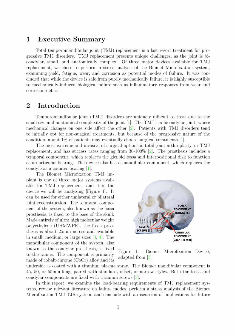
Figure 1: Biomet Microfixation Device,adapted from [3]
The Biomet Microfixation TMJ im-plant is one of three major systems avail-able for TMJ replacement, and it is thedevice we will be analyzing [Figure 1]. Itcan be used for either unilateral or bilateraljoint reconstruction. The temporal compo-nent of the system, also known as the fossaprosthesis, is fixed to the base of the skull.Made entirely of ultra high molecular weightpolyethylene (UHMWPE), the fossa pros-thesis is about 25mm across and availablein small, medium, or large sizes [3, 4]. Themandibular component of the system, alsoknown as the condylar prosthesis, is fixedto the ramus. The component is primarilymade of cobalt-chrome (CoCr) alloy and itsunderside is coated with a titanium plasma spray. The Biomet mandibular component is45, 50, or 55mm long, paired with standard, offset, or narrow styles. Both the fossa andcondylar components are fixed with titanium screws [3].
In this report, we examine the load-bearing requirements of TMJ replacement sys-tems, review relevant literature on failure modes, perform a stress analysis of the BiometMicrofixation TMJ TJR system, and conclude with a discussion of implications for future
1
designs.
3 Analysis of Load-Bearing Requirements
The prosthesis must restore two primary functions of the joint: speech and mastication.For both actions, the joint must have at least 50% of healthy translational and rotationalkinematics. There should be medial-lateral and anterior-posterior translation, and sagittaland transverse plane rotation of the jaw. The TMJ is subjected to primarily compressiveand also shear loads under cyclic loading. Due to incongruent anatomy of the joint, thecontact area is quite small and experiences large stresses during loading [1]. In mastication,incisors transfer the most force to the TMJ (60-90%), whereas molars transfer the least(5-70%) [1, 5]. A TMJ replacement should be able to sustain 800N of compressive loadsand 200N of shear loads for 400,000 cycles per year. As many patients who undergo TMJreplacement are in their 30s, the device should have a lifetime of at least 20 years [1].This project examines possible failure mechanisms under normal loading conditions in theBiomet TMJ replacement system.
4 Stress Analysis of the Biomet Microfixation System
4.1 Overview of Failure Mechanisms
Failure of TMJ total joint replacement (TJR) devices typically manifests as pain aroundthe joint space or a decrease in jaw mobility. Of the three devices on the market today,there is not a significant depth of literature concerning the underlying mechanical failuremodes. It is reasonable to conclude that most TMJ TJR devices on the market today donot fail due to yielding, fracture, or bending, but from wear, corrosion, infection, and otherbiological responses. These latter failures are difficult to predict quantitatively.
In a study of 442 Biomet implants in 228 patients, removals of devices or revisionsurgeries were prompted only by infection or bone formation around the joint space thatlimited opening of the jaw [6]. While this was only a 3-year follow-up, other studies indicatethat revision surgeries with longer follow-up periods were caused by similar bone formation[7, 8]. A 2007 follow-up of patients with custom TMJ Concepts devices revealed that85% reported an increase in quality of life at 10 years [9]. The overall clinical successand lack of revision surgery would suggest that these devices do not undergo mechanicalfailure within 10 years. Another study looked at six patients that presented with symptomsassociated with fibrous capsule formation around the joint. Only one case of six presentedwith inflammatory reactions in surrounding tissue, and none featured foreign body particlesin tissue surrounding the joint space [4]. In a study of 28 failed retrieved Christensenimplants, wear characteristics were observed and discussed, but the failure criteria andmodes were not explicitly defined [10]. As there is not a consensus in medical literaturesuggesting preference for a specific failure mode, we will examine the Biomet Microfixationdevice for failure in yield, fatigue, wear, and corrosion.
2
4.2 Reasonable Failure Criterion
4.2.1 Yield
UHMWPE and CoCr are both ductile materials, as they yield before fracture. Asyielding causes plastic deformation in both materials, yielding in either could change thegeometry of the TJR system and result in significant discomfort or pain. Therefore we treatyielding of either the UHMWPE or CoCr as failure. However, UHMWPE has a lower elasticmodulus and compressive strength, therefore we use a von Mises yielding criterion for theUHMWPE to evaluate safety against yielding in the system. As yielding would precede fastfracture from a single load cycle in this system, we next consider fatigue-mediated fracture.
4.2.2 Fatigue-Mediated Fracture
A total-life philosophy of fatigue and Miner’s rule are used to determine damage in-curred in the device with daily use. Additionally, a defect-tolerant, crack-propagationscheme is used to evaluate device susceptibility to crack growth and fast fracture. Al-though susceptibility to failure by wear is difficult to quantify, we recognize and discussqualitative factors that affect wear mechanisms, including the Hertz contact stresses andfrictional forces at the contact surface that may liberate debris. Likewise, corrosion resis-tance is assessed in terms of material properties of the components, device construction,and implementation. Material properties for UHMWPE and CoCr are listed in 2.
4.3 Loads and boundary conditions
Two loading conditions are considered in the stress analyses: maximum bite force(MBF, 800N) and chewing (mastication, 20-400N, 2000 cycles/day for 20 years) [1, 2]. Theresultant contact forces on the TMJ can be estimated to be at most 70% of the magnitude ofmolar forces; load transfer ratios differ along the mandible and vary based on the dentitionand anatomy of each patient [1]. The joint reaction force is further simplified to be a pointload applied orthogonally to the articular surface, equal in both bearing surfaces. Thearticular surfaces of the CoCr and UHMWPE are assumed to carry no bending moments,though these may occur during eccentric loading or translation.
Grinding, gnashing, and clenching of the teeth (bruxism) represent dynamic and staticloading conditions that introduce significant shear stresses in the teeth, which may transferto the bone-implant interface and cause micromotion and implant loosening [11]. Stressanalyses of bruxism, condylar sliding, and traumatic impact are more complex than canreasonably be approached in this project.
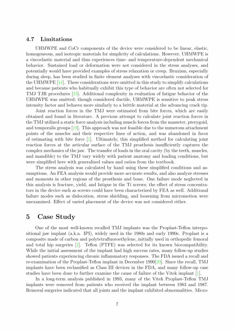
4.4 Geometry
The following analyses are performed assuming a convex CoCr condylar component(radius = 5 mm) articulating upon a fixed, concave UHMWPE fossa component (radius =6.5 mm). These dimensions were estimated by measuring images of a representative devicewith SolidWorks and ImageJ [4] (see appendix C). Though simplification to a concavespheroid is inaccurate (the UHMWPE fossa must permit translation), it is sufficient for
3
this analysis. Furthermore, we altered the geometry and performed several fatigue analysesto test the effect of varying thicknesses and radii of curvature. No analyses were performedon any fixation element of the device in either the fossa or mandibular components, noron the Ti-alloy screws, as these geometries are hard to approximate and failure in fixationelements was not seen clinically.
4.5 Analysis
4.5.1 Yield
Principal stresses in the articular surface of the UHMWPE are calculated from pointloads in MBF and mastication. Equations for Hertz contact theory were obtained [12] andapplied using a MATLAB script (Appendix D). Principal stresses are then used to calculatethe effective von Mises stress at three points in the UHMWPE: directly beneath the pointload, a distance of a away from the point load on the surface, and a distance of 0.51abeneath the point load, where a is the radius of contact of the two surfaces. The maximumvon Mises stress between these points in the UHMWPE are compared to the compressiveyield strength of UHMWPE.
4.5.2 Fatigue
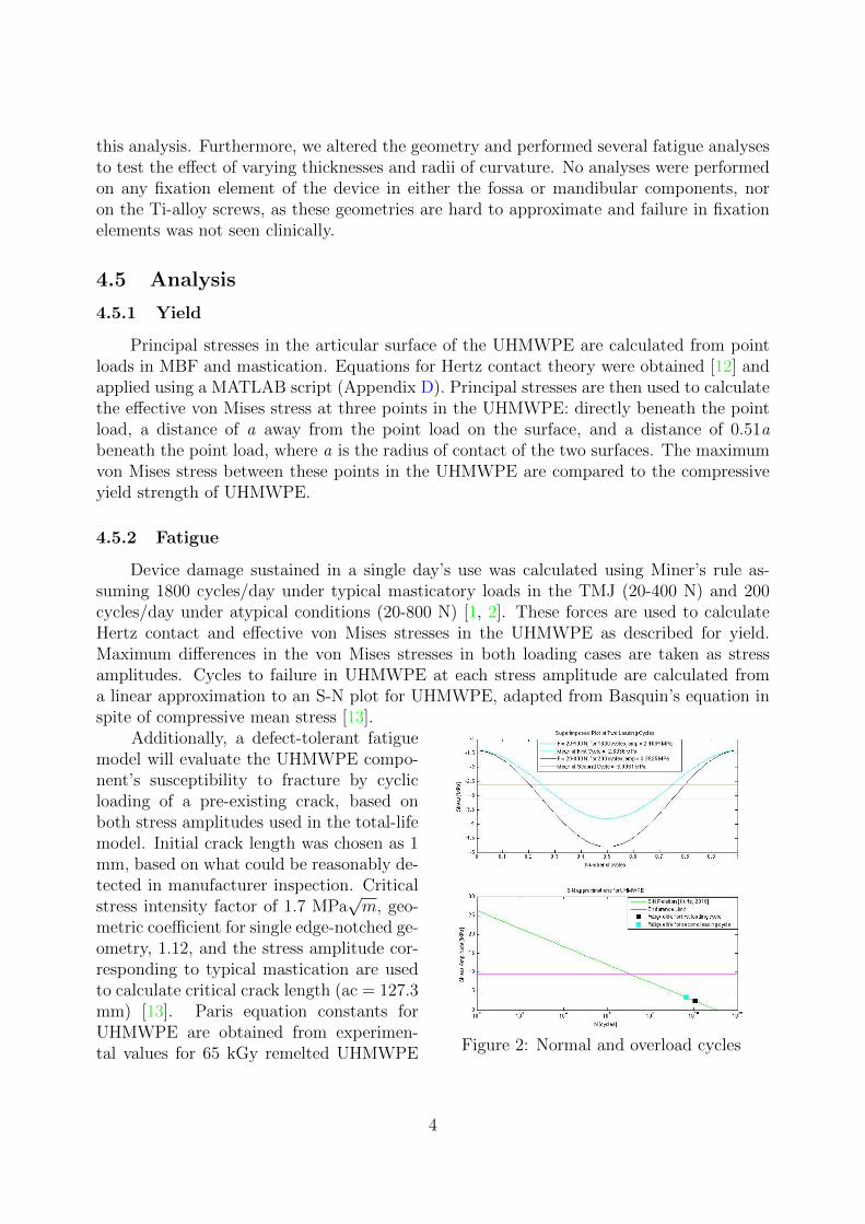
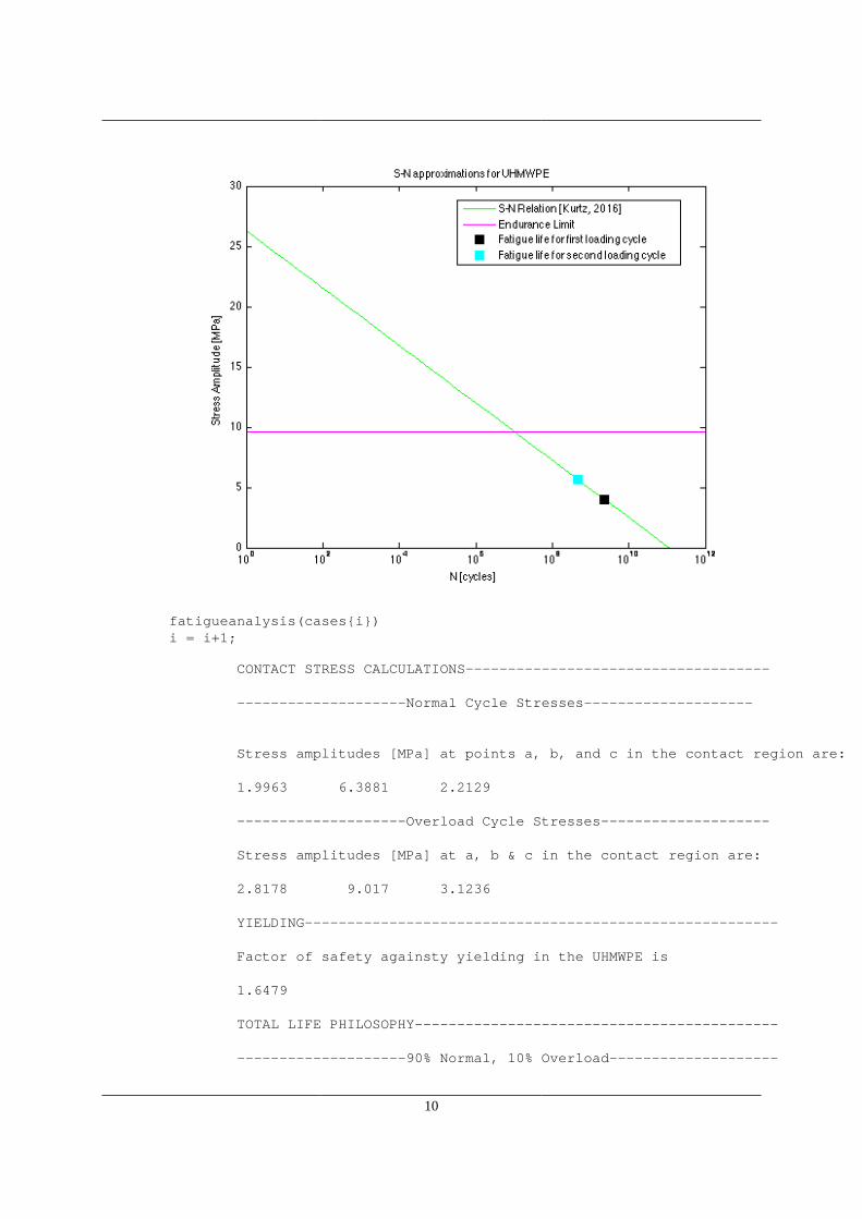
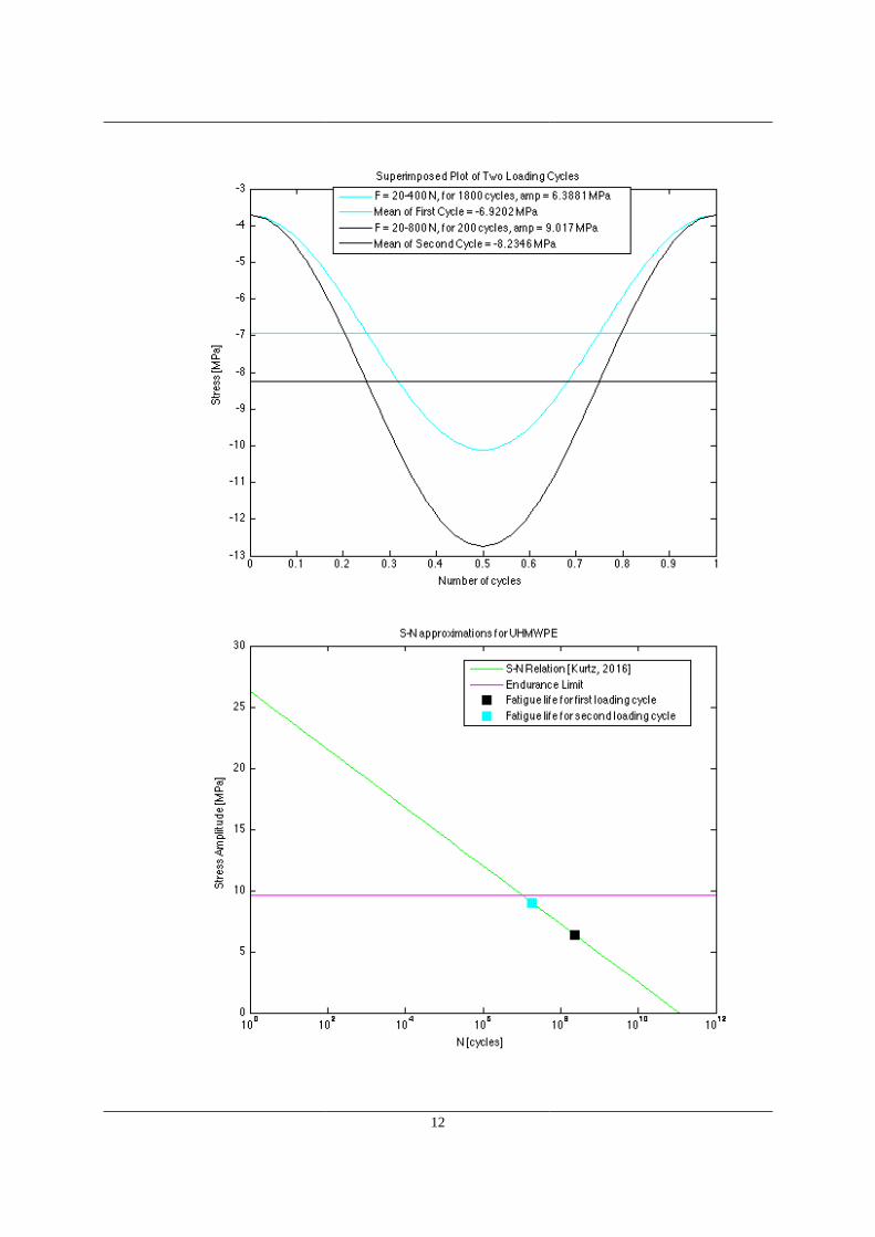
Device damage sustained in a single day’s use was calculated using Miner’s rule as-suming 1800 cycles/day under typical masticatory loads in the TMJ (20-400 N) and 200cycles/day under atypical conditions (20-800 N) [1, 2]. These forces are used to calculateHertz contact and effective von Mises stresses in the UHMWPE as described for yield.Maximum differences in the von Mises stresses in both loading cases are taken as stressamplitudes. Cycles to failure in UHMWPE at each stress amplitude are calculated froma linear approximation to an S-N plot for UHMWPE, adapted from Basquin’s equation inspite of compressive mean stress [13].
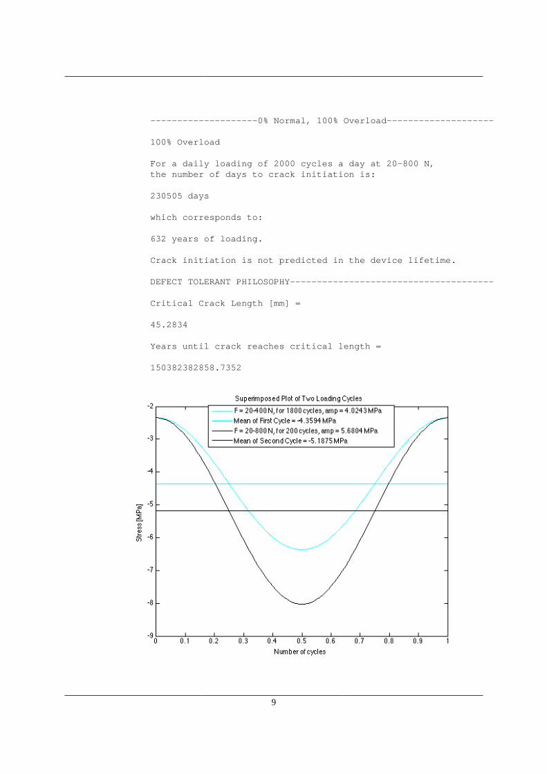
Figure 2: Normal and overload cycles
Additionally, a defect-tolerant fatiguemodel will evaluate the UHMWPE compo-nent’s susceptibility to fracture by cyclicloading of a pre-existing crack, based onboth stress amplitudes used in the total-lifemodel. Initial crack length was chosen as 1mm, based on what could be reasonably de-tected in manufacturer inspection. Criticalstress intensity factor of 1.7 MPa
√m, geo-
metric coefficient for single edge-notched ge-ometry, 1.12, and the stress amplitude cor-responding to typical mastication are usedto calculate critical crack length (ac = 127.3mm) [13]. Paris equation constants forUHMWPE are obtained from experimen-tal values for 65 kGy remelted UHMWPE
4
loaded sinusoidally at frequency of 3 Hz [14]. Cycles to failure under these conditions arepredicted by integrating the Paris equation over the initial and critical crack lengths.
4.5.3 Discussion of Wear
Fatigue may contribute to failure by wear, as wear particles are frequently liberatedas a result from fatigue crack propagation from subsurface defects resulting from shearstress. Wear may be generated by friction forces resulting from translation of the convexCoCr component against the UHMWPE, and cyclic loading of subsurface cracks to causedelamination. Likewise, frictional forces may slough off asperities from the surface of theUHMWPE and generate wear, and surrounding bone or metal debris may result in thirdbody wear. Wear rate studies are usually performed by the device manufacturer and dis-closed to the FDA as preclinical testing. A Summary of Safety and Effectiveness documentfor a similar TMJ replacement listed 0.010 mm
million cyclesof penetration and 0.39 mm3
million cycles
of volumetric wear [15].Ultimately, wear particles may trigger an immune reaction in the surrounding tissue,
which can lead to revision surgery if the patient experiences pain or discomfort. Wearparticles can also elicit an immune response which results in bone resorption and implantloosening [1]. Frictional force can be estimated as the product of compressive force and thecoefficient of friction between CoCr and UHMWPE (max ≈ 800 ∗ 0.094 = 75 N), thoughfurther quantitative analysis of wear is beyond the scope of this project [16].
4.5.4 Discussion of Corrosion
Given the complex and changing conditions in vivo, it is important to consider corro-sion as a possible mechanism for failure. From the surgery for device implantation, therewill be an inflammatory response which triggers production of hydrogen peroxide, proteins,and cytokines. Subsequently, the device will continue to be exposed to biofilms, proteins,and joint fluids. These biological factors contribute to changes in the pH of the environ-ment surrounding the implant, and ultimately accelerate corrosion processes of the TMJprosthesis [17].
In the Biomet Microfixation prosthesis, the condylar surface is at greatest risk for cor-rosion [10]. The condylar component is primarily made of CoCr but coated with Ti, whichhas better corrosion resistance, but presents risk for galvanic corrosion [17]. Manufacturersshould minimize rough surfaces, which are at risk for delamination, which are at risk forcorrsion. Once corrosion begins to roughen the surface of a device, it leaves the implantsusceptible to further corrosion [10].
There is evidence of pitting corrosion and deposited corrosion products in retrievedfailed TMJ implants. Most often, there was a loss of the Ti coating on the condylar head,and underneath, scratches, surface breakdown, and surface cracking [10]. In the absenceof infection, corrosion products were usually the cause of local pain or swelling in patients.Release of metal ions into tissue also induced cytotoxic responses such as decreased enzymeactivity, carcinogenicity, mutagenicity, skeletal and nervous system disorders. In addition tobiological failure, corrosion weakened the devices, thereby limiting lifespan and acceleratingmechanical failure mechanisms [17].
5
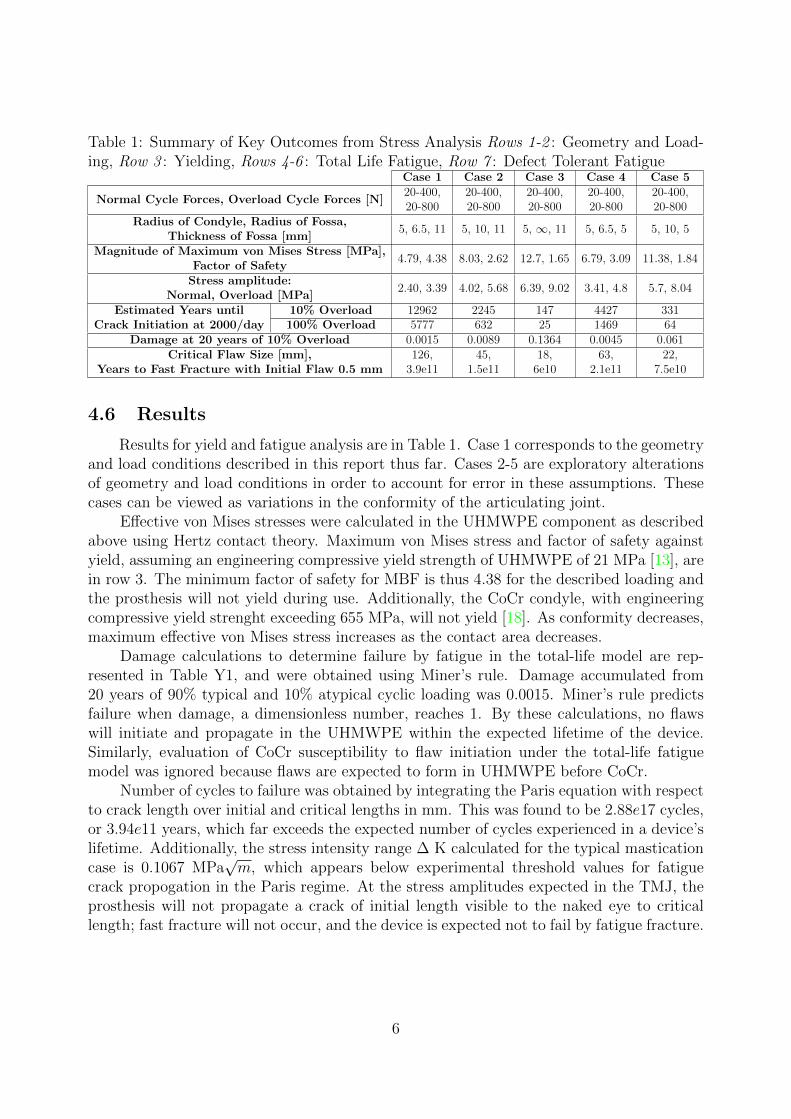
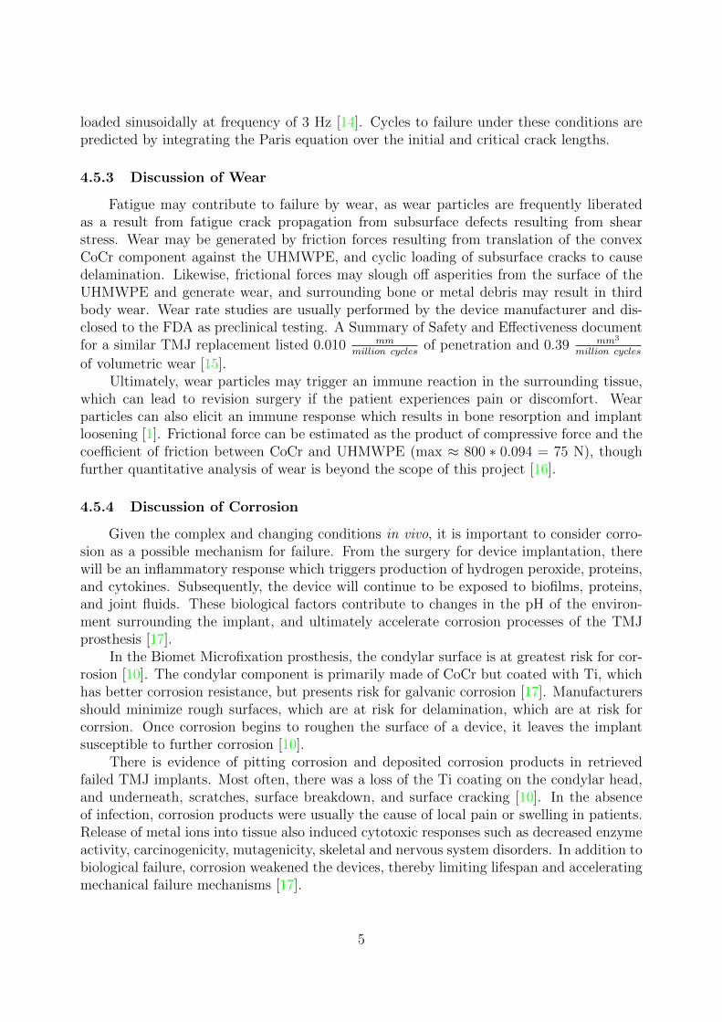
Table 1: Summary of Key Outcomes from Stress Analysis Rows 1-2 : Geometry and Load-ing, Row 3 : Yielding, Rows 4-6 : Total Life Fatigue, Row 7 : Defect Tolerant Fatigue
Case 1 Case 2 Case 3 Case 4 Case 5
Normal Cycle Forces, Overload Cycle Forces [N]20-400,20-800
20-400,20-800
20-400,20-800
20-400,20-800
20-400,20-800
Radius of Condyle, Radius of Fossa,Thickness of Fossa [mm]
5, 6.5, 11 5, 10, 11 5, ∞, 11 5, 6.5, 5 5, 10, 5
Magnitude of Maximum von Mises Stress [MPa],Factor of Safety
4.79, 4.38 8.03, 2.62 12.7, 1.65 6.79, 3.09 11.38, 1.84
Stress amplitude:Normal, Overload [MPa]
2.40, 3.39 4.02, 5.68 6.39, 9.02 3.41, 4.8 5.7, 8.04
Estimated Years untilCrack Initiation at 2000/day
10% Overload 12962 2245 147 4427 331100% Overload 5777 632 25 1469 64
Damage at 20 years of 10% Overload 0.0015 0.0089 0.1364 0.0045 0.061Critical Flaw Size [mm],
Years to Fast Fracture with Initial Flaw 0.5 mm126,
3.9e1145,
1.5e1118,
6e1063,
2.1e1122,
7.5e10
4.6 Results
Results for yield and fatigue analysis are in Table 1. Case 1 corresponds to the geometryand load conditions described in this report thus far. Cases 2-5 are exploratory alterationsof geometry and load conditions in order to account for error in these assumptions. Thesecases can be viewed as variations in the conformity of the articulating joint.
Effective von Mises stresses were calculated in the UHMWPE component as describedabove using Hertz contact theory. Maximum von Mises stress and factor of safety againstyield, assuming an engineering compressive yield strength of UHMWPE of 21 MPa [13], arein row 3. The minimum factor of safety for MBF is thus 4.38 for the described loading andthe prosthesis will not yield during use. Additionally, the CoCr condyle, with engineeringcompressive yield strenght exceeding 655 MPa, will not yield [18]. As conformity decreases,maximum effective von Mises stress increases as the contact area decreases.
Damage calculations to determine failure by fatigue in the total-life model are rep-resented in Table Y1, and were obtained using Miner’s rule. Damage accumulated from20 years of 90% typical and 10% atypical cyclic loading was 0.0015. Miner’s rule predictsfailure when damage, a dimensionless number, reaches 1. By these calculations, no flawswill initiate and propagate in the UHMWPE within the expected lifetime of the device.Similarly, evaluation of CoCr susceptibility to flaw initiation under the total-life fatiguemodel was ignored because flaws are expected to form in UHMWPE before CoCr.
Number of cycles to failure was obtained by integrating the Paris equation with respectto crack length over initial and critical lengths in mm. This was found to be 2.88e17 cycles,or 3.94e11 years, which far exceeds the expected number of cycles experienced in a device’slifetime. Additionally, the stress intensity range ∆ K calculated for the typical masticationcase is 0.1067 MPa
√m, which appears below experimental threshold values for fatigue
crack propogation in the Paris regime. At the stress amplitudes expected in the TMJ, theprosthesis will not propagate a crack of initial length visible to the naked eye to criticallength; fast fracture will not occur, and the device is expected not to fail by fatigue fracture.
6
4.7 Limitations
UHMWPE and CoCr components of the device were considered to be linear, elastic,homogeneous, and isotropic materials for simplicity of calculations. However, UHMWPE isa viscoelastic material and thus experiences time- and temperature-dependent mechanicalbehavior. Sustained load or deformation were not considered in the stress analyses, andpotentially would have provided examples of stress relaxation or creep. Bruxism, especiallyduring sleep, has been studied in finite element analyses with viscoelastic consideration ofthe UHMWPE [11]. These considerations were omitted in this study to simplify calculationsand because patients who habitually exhibit this type of behavior are often not selected forTMJ TJR procedures [15]. Additional complexity in evaluation of fatigue behavior of theUHMWPE was omitted; though considered ductile, UHMWPE is sensitive to peak stressintensity factor and behaves more similarly to a brittle material at the advancing crack tip.
Joint reaction forces in the TMJ were estimated from bite forces, which are easilyobtained and found in literature. A previous attempt to calculate joint reaction forces inthe TMJ utilized a static force analysis including muscle forces from the masseter, pterygoid,and temporalis groups [19]. This approach was not feasible due to the numerous attachmentpoints of the muscles and their respective lines of action, and was abandoned in favorof estimating with bite force [1]. Ultimately, this simplified method for calculating jointreaction forces at the articular surface of the TMJ prosthesis insufficiently captures thecomplex mechanics of the jaw. The transfer of loads in the oral cavity (by the teeth, muscles,and mandible) to the TMJ vary widely with patient anatomy and loading conditions, butwere simplified here with generalized values and ratios from the textbook.
The stress analysis was calculated by hand using these simplified conditions and as-sumptions. An FEA analysis would provide more accurate results, and also analyze stressesand moments in other regions of the prosthesis and bone. One failure mode neglected inthis analysis is fracture, yield, and fatigue in the Ti screws; the effect of stress concentra-tors in the device such as screws could have been characterized by FEA as well. Additionalfailure modes such as dislocation, stress shielding, and loosening from micromotion wereunexamined. Effect of varied placement of the device was not considered either.
5 Case Study
One of the most well-known recalled TMJ implants was the Proplast-Teflon interpo-sitional jaw implant (a.k.a. IPI), widely used in the 1980s and early 1990s. Proplast is acomposite made of carbon and polytetrafluoroethylene, initially used in orthopedic femoraland total hip surgeries [1]. Teflon (PTFE) was selected for its known biocompatibility.While the initial assessment of the implant had high success rates, many follow-up studiesshowed patients experiencing chronic inflammatory responses. The FDA issued a recall andre-examination of the Proplast-Teflon implant in December 1990[20]. Since the recall, TMJimplants have been reclassified as Class III devices in the FDA, and many follow-up casestudies have been done to further examine the cause of failure of the Vitek implant [1].
In a long-term analysis published in 1993, many of the Vitek Proplast-Teflon TMJimplants were removed from patients who received the implant between 1983 and 1987.Removal surgeries indicated that all joints and the implant exhibited abnormalities. Micro-
7
motion of tissues surrounding the implant caused foreign-body giant-cell reactions. Excessloading caused the fragmentation of the implant in situ, which manifested as pain and de-creased function for the patients. These fragmentations are directly linked to the progressivebone degeneration 1-2 years after implantation [21].
Another follow-up case study, published in 2003, evaluated the Vitek Proplast-TeflonTMJ implant in 32 patients in the United States [22]. Each patient was assessed for pain,response to sensory stimuli, quality of life, and autoimmunity. The case study found thatthere was a high correlation between myofascial pain and fibromyalgia. From patients’ bloodsamples, abnormal percentages of T-lymphocytes were found, suggesting their compromisedimmune system have been compromised.
The failure to predict biomechanical stresses in the body caused the failure of theVitek Proplast-Teflon implant. Despite biocompatibility, PTFE tends to disintegrate inload-bearing joints and wear poorly. Despite the initial warnings from DuPont, supplier ofTeflon, Vitek manufactured the device [23]. Due to early pre-market approval, the necessarylong term studies were never performed, leading to the eventual recall of the device [23].
6 Discussion of Future Designs
Preliminary tissue-engineered models for a TMJ disk consist of a polymer scaffoldseeded with chondrocytes and cultured with select growth factors to optimize cartilagetissue growth [24]. Poly-L-lactic acid (PLLA) non-woven meshes have been identified asa viable scaffolding material and a spinning method has been optimized for incorpora-tion of cells [25]. Transforming growth-factor-beta-1 was found to stimulate collagen andglycosaminoglycan production, which improves tissue mechanics [26]. Tissue engineeringallows the regeneration of cartilage that is otherwise unable to self-repair, thus eliminatingthe need for TMJ reconstruction in patients with deficient disks.
Similar to tissue engineering, 3D printing introduces a new degree of tailorability, whichis beneficial to a joint as complex as the TMJ. In 2012, a 3D-printed jaw was successfullyimplanted into a 83-year-old patient. The implant, made of Ti powder with a bioceramiccoating, was constructed in thousands of thin layers and then melted together. The proce-dure lasted one fifth of the time of a standard replacement surgery [27]. Customized fit toa patient’s unique anatomy reduces the risk of chronic inflammation. Further experimenta-tion and investigation is required to assess the performance and biocompatibility of thesefuture designs.
7 Conclusion
Stress analysis on the TMJ total joint replacement indicates that the predominantmodes of failure occur in the form of biological reactions. These occur due to unpredictableloading and sub-optimal placement of the implant. To correct these issues, future designsare aim to increase tailorability to patient-specific anatomy.
8
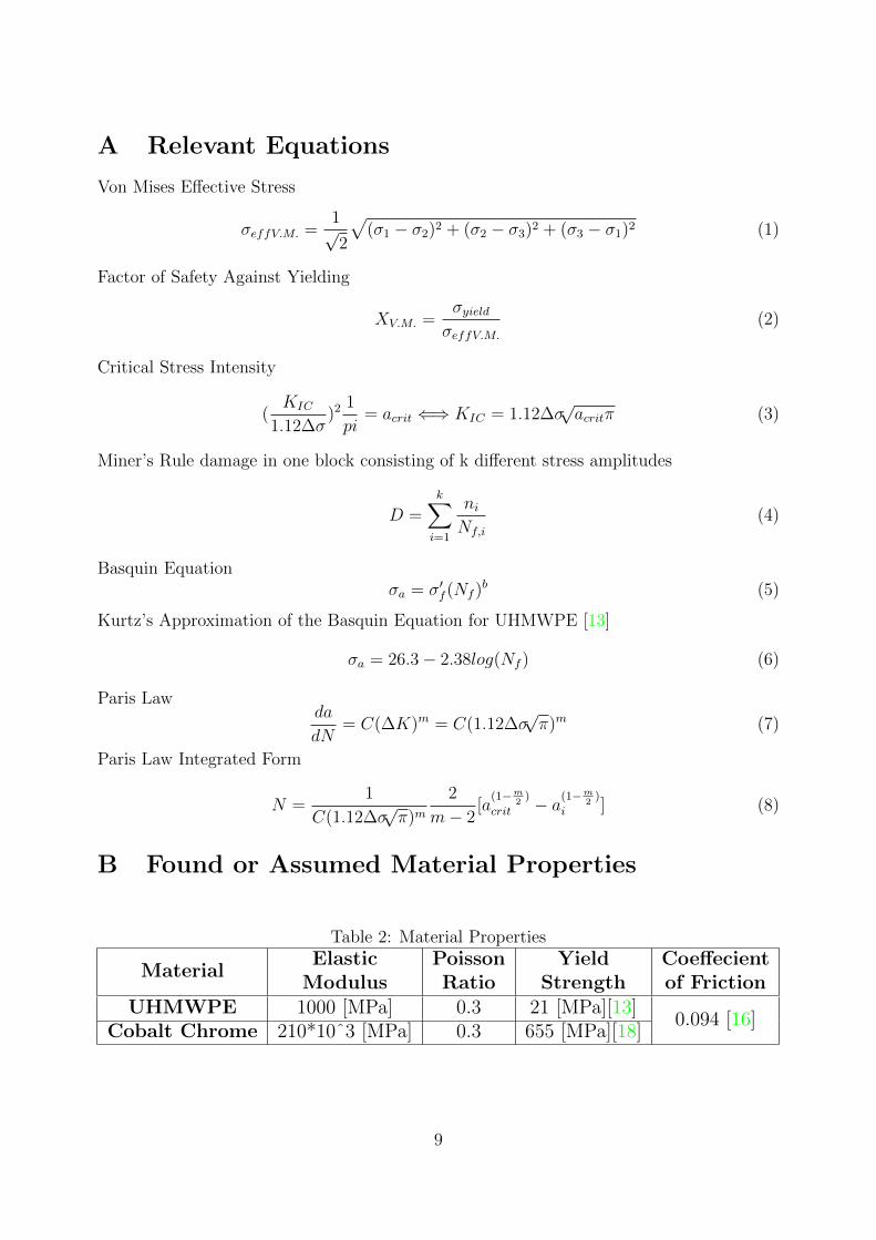
A Relevant Equations
Von Mises Effective Stress
σeffV.M. =1√2
√(σ1 − σ2)2 + (σ2 − σ3)2 + (σ3 − σ1)2 (1)
Factor of Safety Against Yielding
XV.M. =σyieldσeffV.M.
(2)
Critical Stress Intensity
(KIC
1.12∆σ)2
1
pi= acrit ⇐⇒ KIC = 1.12∆σ
√acritπ (3)
Miner’s Rule damage in one block consisting of k different stress amplitudes
D =k∑
i=1
ni
Nf,i
(4)
Basquin Equationσa = σ′f (Nf )b (5)
Kurtz’s Approximation of the Basquin Equation for UHMWPE [13]
σa = 26.3− 2.38log(Nf ) (6)
Paris Lawda
dN= C(∆K)m = C(1.12∆σ
√π)m (7)
Paris Law Integrated Form
N =1
C(1.12∆σ√π)m
2
m− 2[a
(1−m2)
crit − a(1−m2)
i ] (8)
B Found or Assumed Material Properties
Table 2: Material Properties
MaterialElastic
ModulusPoissonRatio
YieldStrength
Coeffecientof Friction
UHMWPE 1000 [MPa] 0.3 21 [MPa][13]0.094 [16]
Cobalt Chrome 210*10ˆ3 [MPa] 0.3 655 [MPa][18]
9
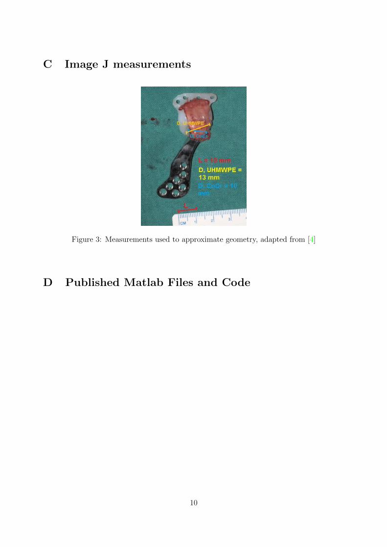
C Image J measurements
Figure 3: Measurements used to approximate geometry, adapted from [4]
D Published Matlab Files and Code
10
1
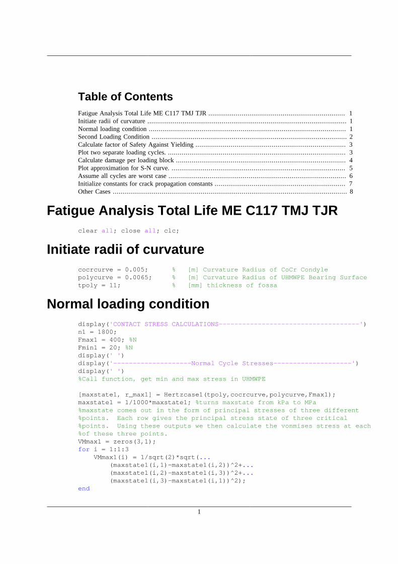
Table of ContentsFatigue Analysis Total Life ME C117 TMJ TJR ...................................................................... 1Initiate radii of curvature ...................................................................................................... 1Normal loading condition ..................................................................................................... 1Second Loading Condition .................................................................................................... 2Calculate factor of Safety Against Yielding ............................................................................. 3Plot two separate loading cycles. ........................................................................................... 3Calculate damage per loading block ....................................................................................... 4Plot approximation for S-N curve. ......................................................................................... 5Assume all cycles are worst case ........................................................................................... 6Initialize constants for crack propagation constants ................................................................... 7Other Cases ........................................................................................................................ 8
Fatigue Analysis Total Life ME C117 TMJ TJRclear all; close all; clc;
Initiate radii of curvaturecocrcurve = 0.005; % [m] Curvature Radius of CoCr Condylepolycurve = 0.0065; % [m] Curvature Radius of UHMWPE Bearing Surfacetpoly = 11; % [mm] thickness of fossa
Normal loading conditiondisplay('CONTACT STRESS CALCULATIONS------------------------------------')n1 = 1800;Fmax1 = 400; %NFmin1 = 20; %Ndisplay(' ')display('--------------------Normal Cycle Stresses--------------------')display(' ')%Call function, get min and max stress in UHMWPE
[maxstate1, r_max1] = Hertzcase1(tpoly,cocrcurve,polycurve,Fmax1);maxstate1 = 1/1000*maxstate1; %turns maxstate from kPa to MPa%maxstate comes out in the form of principal stresses of three different%points. Each row gives the principal stress state of three critical%points. Using these outputs we then calculate the vonmises stress at each%of these three points.VMmax1 = zeros(3,1);for i = 1:1:3 VMmax1(i) = 1/sqrt(2)*sqrt(... (maxstate1(i,1)-maxstate1(i,2))^2+... (maxstate1(i,2)-maxstate1(i,3))^2+... (maxstate1(i,3)-maxstate1(i,1))^2);end

2
VMmax1;%repeat for the minimum force loading.[minstate1, r_min1] = Hertzcase1(tpoly,cocrcurve,polycurve,Fmin1); %[kPa,m]minstate1 = 1/1000*minstate1 ;%turns minstate from kPa to MPa
VMmin1 = zeros(3,1);for i = 1:1:3 VMmin1(i) = 1/sqrt(2)*sqrt(... (minstate1(i,1)-minstate1(i,2))^2+... (minstate1(i,2)-minstate1(i,3))^2+... (minstate1(i,3)-minstate1(i,1))^2);endVMmin1;%find stress amplitudes at three different points.stressamps1 = VMmax1-VMmin1;display(' ')display('Stress amplitudes [MPa] at points a, b, and c in the contact region are:')display(' ')display(num2str(stressamps1'))display(' ')
CONTACT STRESS CALCULATIONS------------------------------------ --------------------Normal Cycle Stresses-------------------- Stress amplitudes [MPa] at points a, b, and c in the contact region are: 0.75106 2.4034 0.83256
Second Loading Conditionn2 = 200;Fmax2 = 800; %NFmin2 = 20; %N
display('--------------------Overload Cycle Stresses--------------------')display(' ')[maxstate2, r_max2] = Hertzcase1(tpoly,cocrcurve,polycurve,Fmax2);maxstate2 = 1/1000*maxstate2; %turns maxstate from kPa to MPa
VMmax2 = zeros(3,1);for i = 1:1:3 VMmax2(i) = 1/sqrt(2)*sqrt(... (maxstate2(i,1)-maxstate2(i,2))^2+... (maxstate2(i,2)-maxstate2(i,3))^2+... (maxstate2(i,3)-maxstate2(i,1))^2);endVMmax2;
%Minimum force loading is the same as above.minstate2 = minstate1;
3
VMmin2 = VMmin1;stressamps2 = VMmax2-VMmin2;
display('Stress amplitudes [MPa] at a, b & c in the contact region are:')display(' ')display(num2str(stressamps2'))display(' ')% The maximum nominal stresses and stress amplitudes for both loading% cycles occur at point B, which is beneath the surface of impact. This% concurs with Hertzian contact stress theory. Now we proceed using these% amplitudes for the two loading cycles to construct a loading block.
--------------------Overload Cycle Stresses-------------------- Stress amplitudes [MPa] at a, b & c in the contact region are: 1.0601 3.3925 1.1752
Calculate factor of Safety Against Yieldingdisplay('YIELDING--------------------------------------------------------')display(' ')yieldstress = 21; %[MPa]maxVMstress = max([VMmax1; VMmax2]);FOS = yieldstress/maxVMstress;display('Factor of safety againsty yielding in the UHMWPE is ')display(' ')display(num2str(FOS))display(' ')
YIELDING-------------------------------------------------------- Factor of safety againsty yielding in the UHMWPE is 4.3802
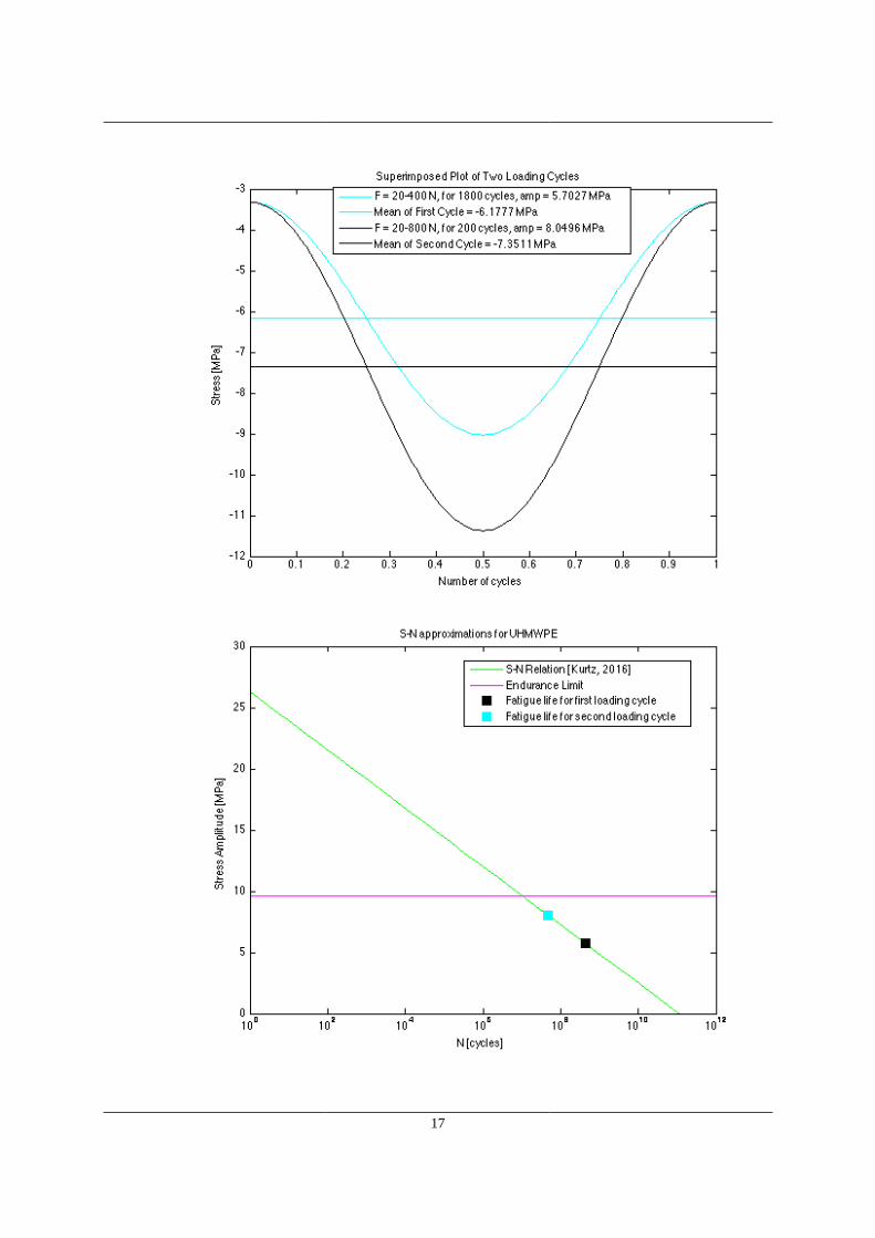
Plot two separate loading cycles.%Store the stressamplitudes of different loading cycles more conveniently.amp1 = stressamps1(2);amp2 = stressamps2(2);%find the mean stress of the loading cyclescenter1 = (VMmax1(2)+VMmin1(2))/2;center2 = (VMmax2(2)+VMmin2(2))/2;t = 0:0.01:1;
figure()plot(t,-amp1/2*cos(2*pi*t+pi)-center1,'-c')hold onplot(t,-center1*ones(size(t)),'c')
4
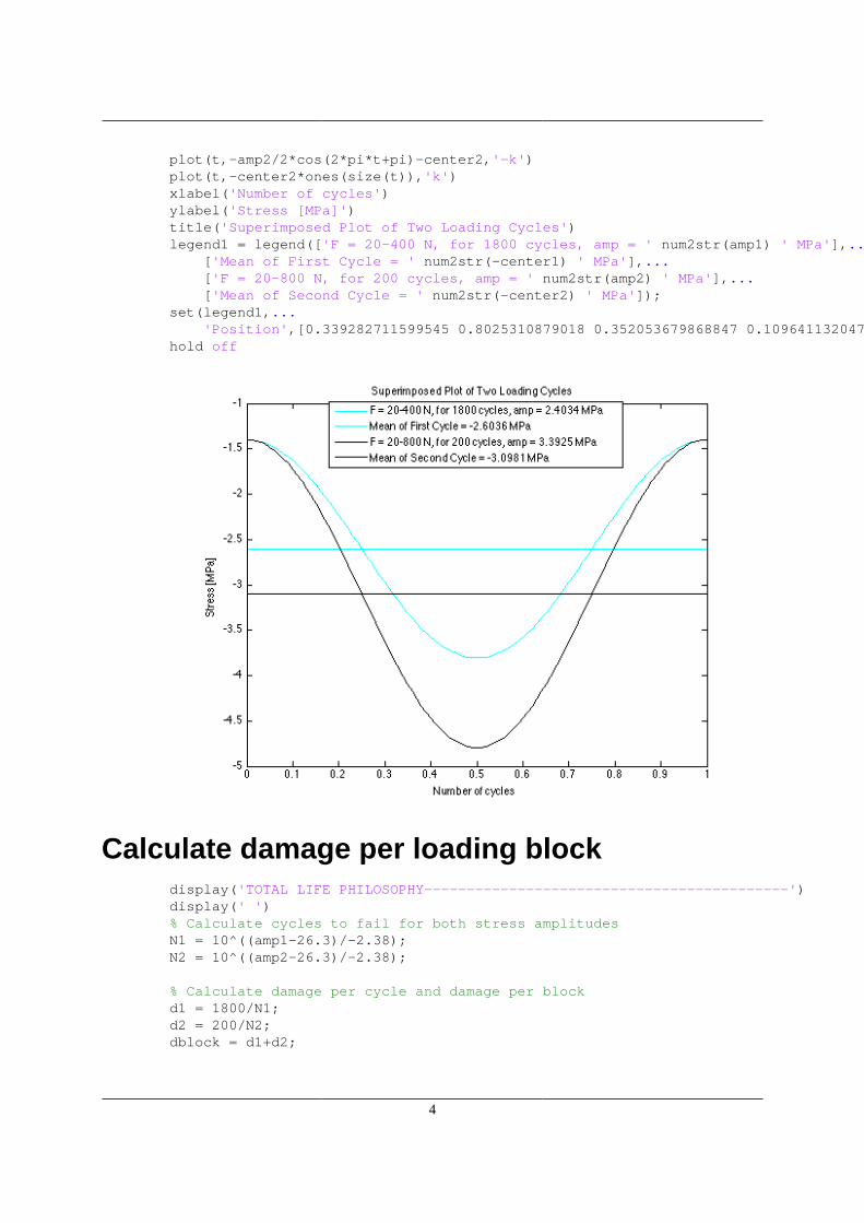
plot(t,-amp2/2*cos(2*pi*t+pi)-center2,'-k')plot(t,-center2*ones(size(t)),'k')xlabel('Number of cycles')ylabel('Stress [MPa]')title('Superimposed Plot of Two Loading Cycles')legend1 = legend(['F = 20-400 N, for 1800 cycles, amp = ' num2str(amp1) ' MPa'],... ['Mean of First Cycle = ' num2str(-center1) ' MPa'],... ['F = 20-800 N, for 200 cycles, amp = ' num2str(amp2) ' MPa'],... ['Mean of Second Cycle = ' num2str(-center2) ' MPa']);set(legend1,... 'Position',[0.339282711599545 0.8025310879018 0.352053679868847 0.109641132047887]);hold off
Calculate damage per loading blockdisplay('TOTAL LIFE PHILOSOPHY-------------------------------------------')display(' ')% Calculate cycles to fail for both stress amplitudesN1 = 10^((amp1-26.3)/-2.38);N2 = 10^((amp2-26.3)/-2.38);
% Calculate damage per cycle and damage per blockd1 = 1800/N1;d2 = 200/N2;dblock = d1+d2;
5
% Damage at 20 yearsd20years = dblock*365*20;
% Calculate blocks (days) to faildays = 1/dblock;years = days/365;display('--------------------90% Normal, 10% Overload--------------------')display(' ')display('For a daily loading block of 2000 cycles a day, with 1800 at')display('20-400 N and 200 at 20-800 N the days to crack initiation is: ')display(' ')display([num2str(round(days)) ' days, which corresponds to: '])display(' ')display([num2str(round(years)) ' years of loading.'])display(' ')if years>20 display('Crack initiation is not predicted at the 20 year mark.')else display('Crack initiation is predicted to occur by the 20 year mark.')enddisplay(' ')
TOTAL LIFE PHILOSOPHY------------------------------------------- --------------------90% Normal, 10% Overload-------------------- For a daily loading block of 2000 cycles a day, with 1800 at20-400 N and 200 at 20-800 N the days to crack initiation is: 4731159 days, which corresponds to: 12962 years of loading. Crack initiation is not predicted at the 20 year mark.
Plot approximation for S-N curve.%approximation for S-N curve was taken from "UHMWPE Biomaterials Handbook"%by Steven M. Kurtz. Full citation is in bibliography
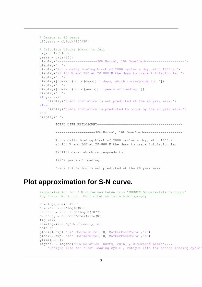
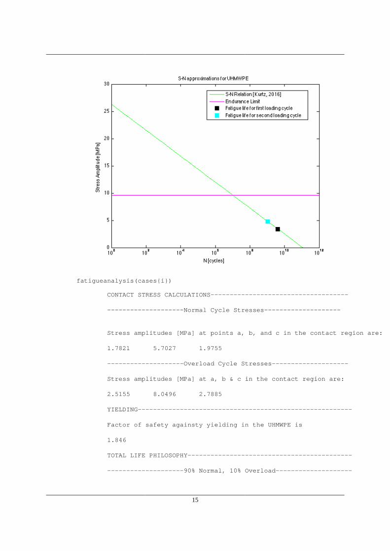
N = logspace(0,12);S = 26.3-2.38*log10(N);Srunout = 26.3-2.38*log10(10^7);Srunouty = Srunout*ones(size(N));figure()semilogx(N,S,'g',N,Srunouty,'m')hold onplot(N1,amp1,'sk','MarkerSize',10,'MarkerFaceColor','k')plot(N2,amp2,'sc','MarkerSize',10,'MarkerFaceColor','c')ylim([0,30])legend2 = legend('S-N Relation [Kurtz, 2016]','Endurance Limit',... 'Fatigue life for first loading cycle','Fatigue life for second loading cycle');
6
set(legend2,... 'Position',[0.485581906264082 0.7487183317985 0.376904010815683 0.146449226378248]);xlabel('N [cycles]')ylabel('Stress Amplitude [MPa]')title('S-N approximations for UHMWPE')
Assume all cycles are worst casedisplay('--------------------0% Normal, 100% Overload--------------------')display(' ')Ntotal = N2;baddays = N2/2000;badyears = baddays/365;display('100% Overload')display(' ')display('For a daily loading of 2000 cycles a day at 20-800 N,')display('the number of days to crack initiation is: ')display(' ')display([num2str(round(baddays)) ' days'])display(' ')display('which corresponds to: ')display(' ')display([num2str(round(badyears)) ' years of loading.'])display(' ')if badyears>20 display('Crack initiation is not predicted in the device lifetime.')
7
else display('Crack initiation is predicted to occur by the 20 year mark')enddisplay(' ')
--------------------0% Normal, 100% Overload-------------------- 100% Overload For a daily loading of 2000 cycles a day at 20-800 N,the number of days to crack initiation is: 2108557 days which corresponds to: 5777 years of loading. Crack initiation is not predicted in the device lifetime.
Initialize constants for crack propagation con-stants
display('DEFECT TOLERANT PHILOSOPHY--------------------------------------')display(' ')ai = .5; % [mm]m = 5.81;c = 3.6*10^-4;Kc = 1.7;amp = amp1; %use amplitude from the overload cycle for a worst case eval.ac = (1/pi)*(Kc/(1.12*amp))^2; % [m]acrit = ac*1000; % [mm]display('Critical Crack Length [mm] = ')display(' ')display(num2str(acrit))display(' ')
%calculate N to fast fractureN = (2/(m-2))*(1/(c*1.12*amp*sqrt(pi)))^m*(ac^(1-m/2)-ai^(1-m/2));%[cycles]
%Convert to yearsyearsprop = N/(2000*365);display('Years until crack reaches critical length = ')display(' ')display(num2str(yearsprop))display(' ')
DEFECT TOLERANT PHILOSOPHY-------------------------------------- Critical Crack Length [mm] =
8
126.9585 Years until crack reaches critical length = 394721969501.4122
Other Cases% fatigueanalysis is just a function that runs the above script for given% radii of curvature of CoCr and UHMWPE.i = 1;case2=[0.005,0.01,11];case3=[0.005,10^200,11];case4=[0.005,0.0065,5];case5=[0.005,0.01,5];cases = {case2, case3, case4, case5};
fatigueanalysis(cases{i})i = i+1;
CONTACT STRESS CALCULATIONS------------------------------------ --------------------Normal Cycle Stresses-------------------- Stress amplitudes [MPa] at points a, b, and c in the contact region are: 1.2576 4.0243 1.394 --------------------Overload Cycle Stresses-------------------- Stress amplitudes [MPa] at a, b & c in the contact region are: 1.7751 5.6804 1.9677 YIELDING-------------------------------------------------------- Factor of safety againsty yielding in the UHMWPE is 2.6159 TOTAL LIFE PHILOSOPHY------------------------------------------- --------------------90% Normal, 10% Overload-------------------- For a daily loading block of 2000 cycles a day, with 1800 at20-400 N and 200 at 20-800 N the days to crack initiation is: 819425 days, which corresponds to: 2245 years of loading. Crack initiation is not predicted at the 20 year mark.
9
--------------------0% Normal, 100% Overload-------------------- 100% Overload For a daily loading of 2000 cycles a day at 20-800 N,the number of days to crack initiation is: 230505 days which corresponds to: 632 years of loading. Crack initiation is not predicted in the device lifetime. DEFECT TOLERANT PHILOSOPHY-------------------------------------- Critical Crack Length [mm] = 45.2834 Years until crack reaches critical length = 150382382858.7352
10
fatigueanalysis(cases{i})i = i+1;
CONTACT STRESS CALCULATIONS------------------------------------ --------------------Normal Cycle Stresses-------------------- Stress amplitudes [MPa] at points a, b, and c in the contact region are: 1.9963 6.3881 2.2129 --------------------Overload Cycle Stresses-------------------- Stress amplitudes [MPa] at a, b & c in the contact region are: 2.8178 9.017 3.1236 YIELDING-------------------------------------------------------- Factor of safety againsty yielding in the UHMWPE is 1.6479 TOTAL LIFE PHILOSOPHY------------------------------------------- --------------------90% Normal, 10% Overload--------------------
11
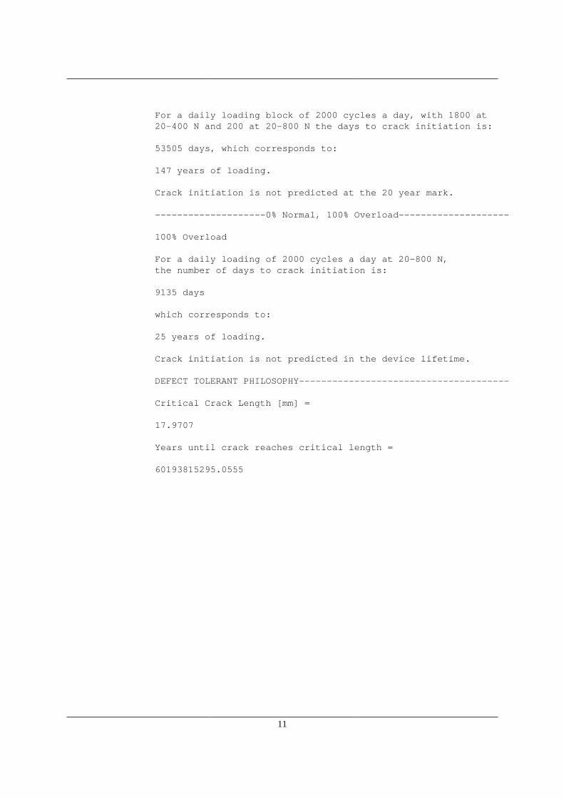
For a daily loading block of 2000 cycles a day, with 1800 at20-400 N and 200 at 20-800 N the days to crack initiation is: 53505 days, which corresponds to: 147 years of loading. Crack initiation is not predicted at the 20 year mark. --------------------0% Normal, 100% Overload-------------------- 100% Overload For a daily loading of 2000 cycles a day at 20-800 N,the number of days to crack initiation is: 9135 days which corresponds to: 25 years of loading. Crack initiation is not predicted in the device lifetime. DEFECT TOLERANT PHILOSOPHY-------------------------------------- Critical Crack Length [mm] = 17.9707 Years until crack reaches critical length = 60193815295.0555
12
13
fatigueanalysis(cases{i})i = i+1;
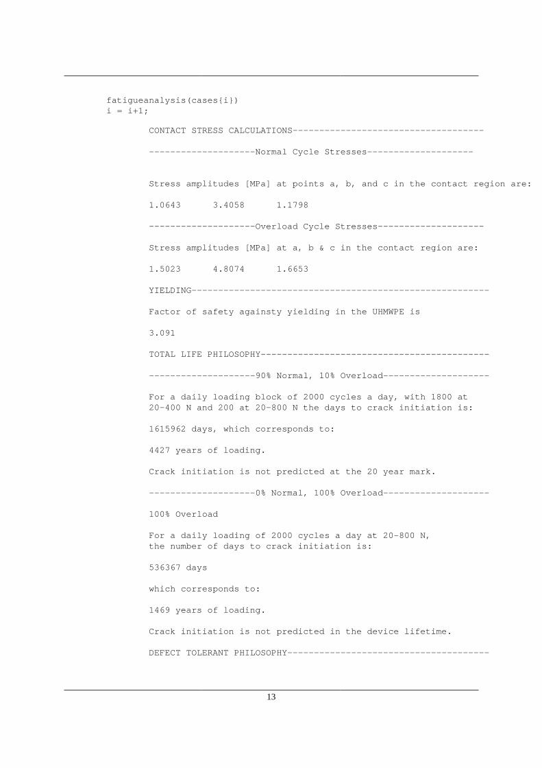
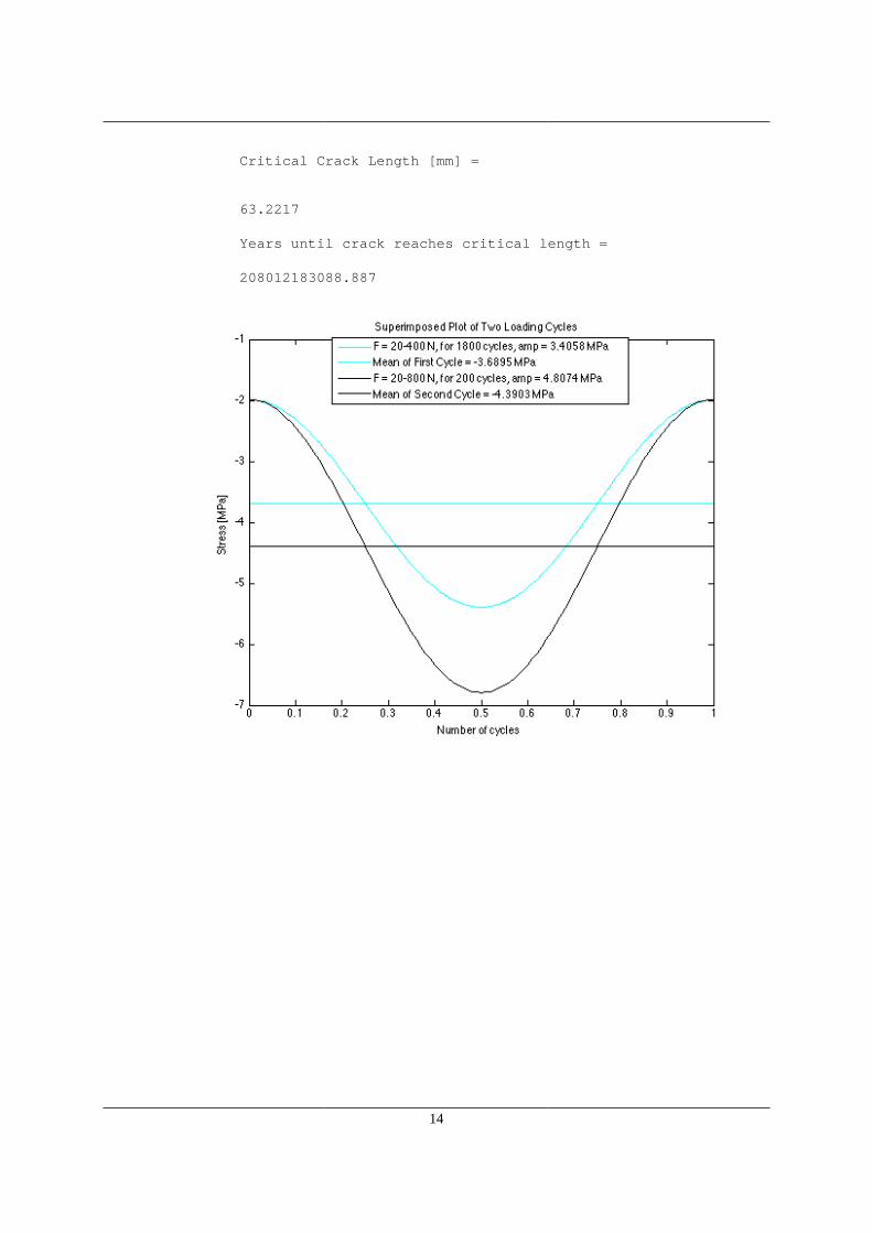
CONTACT STRESS CALCULATIONS------------------------------------ --------------------Normal Cycle Stresses-------------------- Stress amplitudes [MPa] at points a, b, and c in the contact region are: 1.0643 3.4058 1.1798 --------------------Overload Cycle Stresses-------------------- Stress amplitudes [MPa] at a, b & c in the contact region are: 1.5023 4.8074 1.6653 YIELDING-------------------------------------------------------- Factor of safety againsty yielding in the UHMWPE is 3.091 TOTAL LIFE PHILOSOPHY------------------------------------------- --------------------90% Normal, 10% Overload-------------------- For a daily loading block of 2000 cycles a day, with 1800 at20-400 N and 200 at 20-800 N the days to crack initiation is: 1615962 days, which corresponds to: 4427 years of loading. Crack initiation is not predicted at the 20 year mark. --------------------0% Normal, 100% Overload-------------------- 100% Overload For a daily loading of 2000 cycles a day at 20-800 N,the number of days to crack initiation is: 536367 days which corresponds to: 1469 years of loading. Crack initiation is not predicted in the device lifetime. DEFECT TOLERANT PHILOSOPHY--------------------------------------
14
Critical Crack Length [mm] =
63.2217 Years until crack reaches critical length = 208012183088.887
15
fatigueanalysis(cases{i})
CONTACT STRESS CALCULATIONS------------------------------------ --------------------Normal Cycle Stresses-------------------- Stress amplitudes [MPa] at points a, b, and c in the contact region are: 1.7821 5.7027 1.9755 --------------------Overload Cycle Stresses-------------------- Stress amplitudes [MPa] at a, b & c in the contact region are: 2.5155 8.0496 2.7885 YIELDING-------------------------------------------------------- Factor of safety againsty yielding in the UHMWPE is 1.846 TOTAL LIFE PHILOSOPHY------------------------------------------- --------------------90% Normal, 10% Overload--------------------
16
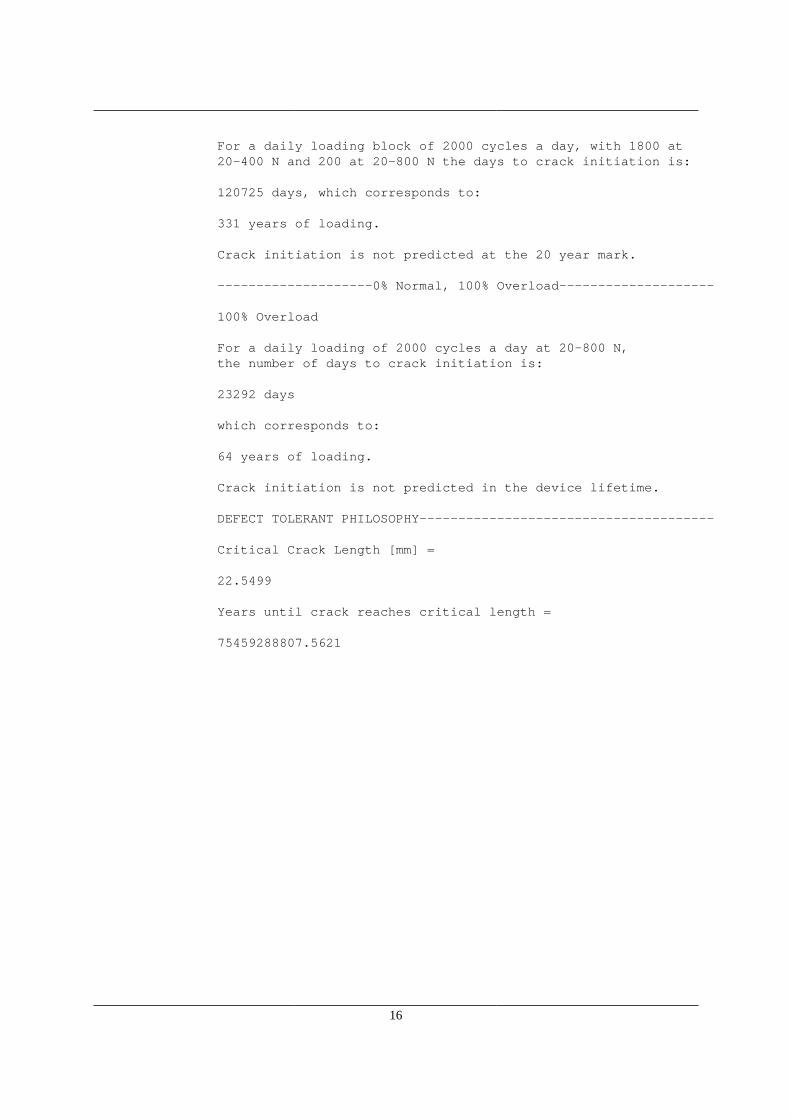
For a daily loading block of 2000 cycles a day, with 1800 at20-400 N and 200 at 20-800 N the days to crack initiation is: 120725 days, which corresponds to: 331 years of loading. Crack initiation is not predicted at the 20 year mark. --------------------0% Normal, 100% Overload-------------------- 100% Overload For a daily loading of 2000 cycles a day at 20-800 N,the number of days to crack initiation is: 23292 days which corresponds to: 64 years of loading. Crack initiation is not predicted in the device lifetime. DEFECT TOLERANT PHILOSOPHY-------------------------------------- Critical Crack Length [mm] = 22.5499 Years until crack reaches critical length = 75459288807.5621
17
1
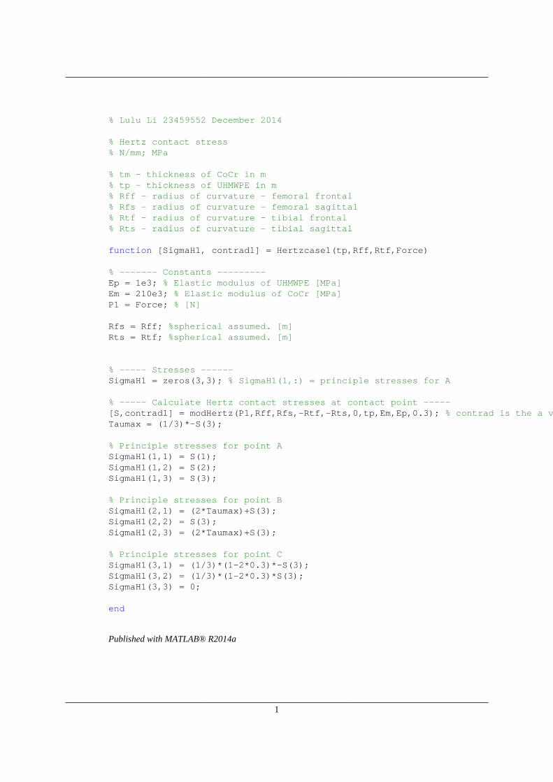
% Lulu Li 23459552 December 2014
% Hertz contact stress% N/mm; MPa
% tm - thickness of CoCr in m% tp - thickness of UHMWPE in m% Rff - radius of curvature - femoral frontal% Rfs - radius of curvature - femoral sagittal% Rtf - radius of curvature - tibial frontal% Rts - radius of curvature - tibial sagittal
function [SigmaH1, contrad1] = Hertzcase1(tp,Rff,Rtf,Force)
% ------- Constants ---------Ep = 1e3; % Elastic modulus of UHMWPE [MPa]Em = 210e3; % Elastic modulus of CoCr [MPa]P1 = Force; % [N]
Rfs = Rff; %spherical assumed. [m]Rts = Rtf; %spherical assumed. [m]
% ----- Stresses ------SigmaH1 = zeros(3,3); % SigmaH1(1,:) = principle stresses for A
% ----- Calculate Hertz contact stresses at contact point -----[S,contrad1] = modHertz(P1,Rff,Rfs,-Rtf,-Rts,0,tp,Em,Ep,0.3); % contrad is the a variable returned by modHertzTaumax = (1/3)*-S(3);
% Principle stresses for point ASigmaH1(1,1) = S(1);SigmaH1(1,2) = S(2);SigmaH1(1,3) = S(3);
% Principle stresses for point BSigmaH1(2,1) = (2*Taumax)+S(3);SigmaH1(2,2) = S(3);SigmaH1(2,3) = (2*Taumax)+S(3);
% Principle stresses for point CSigmaH1(3,1) = (1/3)*(1-2*0.3)*-S(3);SigmaH1(3,2) = (1/3)*(1-2*0.3)*S(3);SigmaH1(3,3) = 0;
end
Published with MATLAB® R2014a
1
% Lulu Li 23459552 December 2014
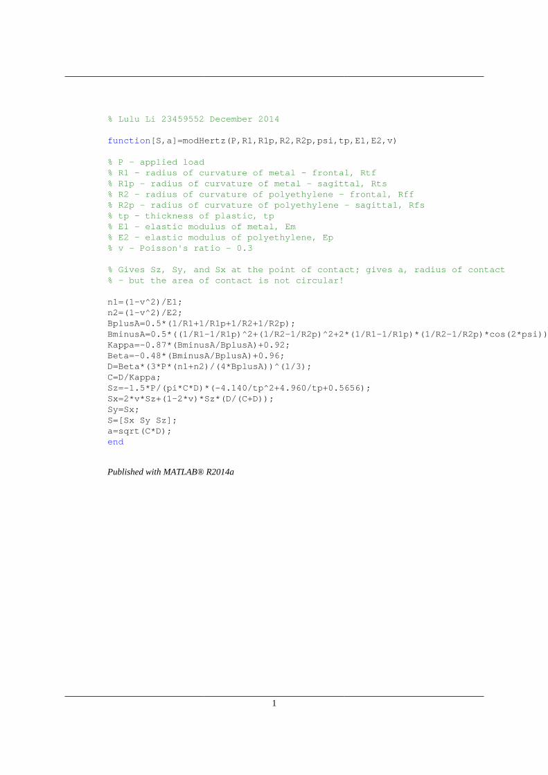
function[S,a]=modHertz(P,R1,R1p,R2,R2p,psi,tp,E1,E2,v)
% P - applied load% R1 - radius of curvature of metal - frontal, Rtf% R1p - radius of curvature of metal - sagittal, Rts% R2 - radius of curvature of polyethylene - frontal, Rff% R2p - radius of curvature of polyethylene - sagittal, Rfs% tp - thickness of plastic, tp% E1 - elastic modulus of metal, Em% E2 - elastic modulus of polyethylene, Ep% v - Poisson's ratio - 0.3
% Gives Sz, Sy, and Sx at the point of contact; gives a, radius of contact% - but the area of contact is not circular!
n1=(1-v^2)/E1;n2=(1-v^2)/E2;BplusA=0.5*(1/R1+1/R1p+1/R2+1/R2p);BminusA=0.5*((1/R1-1/R1p)^2+(1/R2-1/R2p)^2+2*(1/R1-1/R1p)*(1/R2-1/R2p)*cos(2*psi))^0.5;Kappa=-0.87*(BminusA/BplusA)+0.92;Beta=-0.48*(BminusA/BplusA)+0.96;D=Beta*(3*P*(n1+n2)/(4*BplusA))^(1/3);C=D/Kappa;Sz=-1.5*P/(pi*C*D)*(-4.140/tp^2+4.960/tp+0.5656);Sx=2*v*Sz+(1-2*v)*Sz*(D/(C+D));Sy=Sx;S=[Sx Sy Sz];a=sqrt(C*D);end
Published with MATLAB® R2014a
References
[1] Pruitt L, Chakravartula A. Mechanics of biomaterials. Cambridge: Cambridge Univer-sity Press; 2011.
[2] Huang H, Su K, Fuh L, Chen M, Wu J, Tsai M et al. Biomechanical analysis of atemporomandibular joint condylar prosthesis during various clenching tasks. Journalof Cranio-Maxillofacial Surgery [Internet]. 2015 [cited 16 March 2016];43(7):1194-1201.Available from: http://www.sciencedirect.com/science/article/pii/S1010518215001201
[3] [Internet]. Biomet.com. 2016 [cited 16 March 2016]. Available from: Biomet website(link abbreviated)
[4] Westermark A, Leiggener C, Aagaard E, Lindskog S. Histological find-ings in soft tissues around temporomandibular joint prostheses after upto eight years of function. International Journal of Oral and MaxillofacialSurgery [Internet]. 2011 [cited 16 March 2016];40(1):18-25. Available from:http://www.sciencedirect.com/science/article/pii/S0901502710004029
[5] Smith D, McLachlan K, McCall W. A Numerical Model of Temporomandibular JointLoading. Journal of Dental Research [Internet]. 1986;65(8):1046-1052. Available from:http://jdr.sagepub.com/content/65/8/1046.full.pdf
[6] Giannakopoulos H, Sinn D, Quinn P. Biomet Microfixation Temporo-mandibular Joint Replacement System: A 3-Year Follow-Up Study of Pa-tients Treated During 1995 to 2005. Journal of Oral and MaxillofacialSurgery [Internet]. 2012 [cited 16 March 2016];70(4):787-794. Available from:http://www.sciencedirect.com/science/article/pii/S0278239111015394
[7] Pinto L, Wolford L, Buschang P, Bernardi F, Goncalves J, Cassano D. Maxillo-mandibular counter-clockwise rotation and mandibular advancement with TMJConcepts R© total joint prostheses. International Journal of Oral and Maxillofa-cial Surgery [Internet]. 2009 [cited 16 March 2016];38(4):326-331. Available from:http://www.sciencedirect.com/science/article/pii/S0901502708004189?np=y
[8] Guarda-Nardini L, Manfredini D, Olivo M, Ferronato G. Long-Term Symptoms Onsetand Heterotopic Bone Formation around a Total Temporomandibular Joint Prosthe-sis: a Case Report. JOMR [Internet]. 2014 [cited 16 March 2016];5(1). Available from:http://www.ncbi.nlm.nih.gov/pmc/articles/PMC4007372/
[9] Mercuri L, Edibam N, Giobbie-Hurder A. Fourteen-Year Follow-Up of a Patient-FittedTotal Temporomandibular Joint Reconstruction System. Journal of Oral and Maxillo-facial Surgery [Internet]. 2007 [cited 16 March 2016];65(6):1140-1148. Available from:http://www.sciencedirect.com/science/article/pii/S0278239106018830
[10] Kerwell S, Alfaro M, Pourzal R, Lundberg H, Liao Y, Sukotjo C et al.Examination of failed retrieved temporomandibular joint (TMJ) implants. ActaBiomaterialia [Internet]. 2016 [cited March 16 2016];32:324-335. Available from:http://www.sciencedirect.com/science/article/pii/S1742706116300010
30
[11] Abe S, Kawano F, Kohge K, Kawaoka T, Ueda K, Hattori-Hara E et al. Stress analysisin human temporomandibular joint affected by anterior disc displacement during pro-longed clenching. J Oral Rehabil [Internet]. 2013 [cited March 16 2016];40(4):239-246.Available from: http://www.ncbi.nlm.nih.gov/pubmed/23398635
[12] Bartel D, Bicknell V, Wright T. The effect of conformity, thickness, and material onstresses in ultra-high molecular weight components for total joint replacement. The Jour-nal of Bone and Joint Surgery [Internet]. 2016 [cited 16 March 2016];68-A(7). Availablefrom: http://jbjs.org/content/jbjsam/68/7/1041.full.pdf
[13] Kurtz S. UHMWPE biomaterials handbook. Amsterdam ; London: Academic Press;2009. 694-700. https://books.google.com/books?isbn=0323354351
[14] Sirimamilla A, Furmanski J, Rimnac C. Peak stress intensity factor gov-erns crack propagation velocity in crosslinked ultrahigh-molecular-weightpolyethylene. Journal of Biomedical Materials Research Part B: Applied Bio-materials [Internet]. 2012 [cited 16 March 2016];:n/a-n/a. Available from:http://www.ncbi.nlm.nih.gov/pmc/articles/PMC3825479/
[15] P980052 Summary of Safety and Effectiveness [Inter-net]. FDA.gov. 2016 [cited 16 March 2016]. Available from:http://www.accessdata.fda.gov/cdrh docs/pdf/P980052b.pdf
[16] Kutz M. Handbook of Materials Selection [Internet]. Google Books. 2016 [cited 16March 2016]. Available from: https://books.google.com/books?isbn=0471359246
[17] Royhman D, Radhakrishnan R, Yuan J, Mathew M, Mercuri L, Sukotjo C. Anelectrochemical investigation of TMJ implant metal alloys in an artificial jointfluid environment: The influence of pH variation. Journal of Cranio-MaxillofacialSurgery [Internet]. 2014 [cited 16 March 2016];42(7):1052-1061. Available from:http://www.sciencedirect.com/science/article/pii/S1010518214000316
[18] ASTM F75 CoCr Alloy [Internet]. Arcam.com. 2016 [cited 16 March 2016]. Avail-able from: http://www.arcam.com/wp-content/uploads/Arcam-ASTM-F75-Cobalt-Chrome.pdf
[19] Ackland D, Moskaljuk A, Hart C, Vee Sin Lee P, Dimitroulis G. Prosthesis Load-ing After Temporomandibular Joint Replacement Surgery: A Musculoskeletal Mod-eling Study. Journal of Biomechanical Engineering [Internet]. 2015 [cited 16 March2016];137(4):041001. Available from: http://www.ncbi.nlm.nih.gov/pubmed/25565306
[20] Burlington B, Gundaker W. Important Information About TMJ Im-plants [Internet]. Fda.gov. 2016 [cited 16 March 2016]. Available from:http://www.fda.gov/MedicalDevices/Safety/AlertsandNotices/PublicHealthNotifications/ucm243871.htm
[21] Feinerman D, Piecuch J. Long-term retrospective analysis of twenty-three Proplast R©-Teflon R© temporomandibular joint interpositional implants. International Journal of
31
Oral and Maxillofacial Surgery [Internet]. 1993 [cited 16 March 2016];22(1):11-16. Avail-able from: http://www.sciencedirect.com/science/article/pii/S0901502705803480
[22] Ta L, Phero J, Pillemer S, Hale-Donze H, McCartney-Francis N, Kingman A et al. Clin-ical evaluation of patients with temporomandibular joint implants. Journal of Oral andMaxillofacial Surgery [Internet]. 2002 [cited 16 March 2016];60(12):1389-1399. Availablefrom: http://www.sciencedirect.com/science/article/pii/S027823910200633X
[23] Anguiano v. EI DuPont De Nemours and Co., Inc., 808 F. Supp. 719(D. Ariz. 1992) [Internet]. Justia Law. 2016 [cited 16 March 2016]. Availablefrom: http://law.justia.com/cases/federal/district-courts/FSupp/808/719/1478400/http://law.justia.com/cases/federal/district-courts/FSupp/808/719/1478400/
[24] Naujoks C, Meyer U, Wiesmann H, Jasche-Meyer J, Hohoff A, Depprich R etal. Principles of cartilage tissue engineering in TMJ reconstruction. Head & FaceMedicine [Internet]. 2008 [cited 16 March 2016];4(1):3. Available from: http://head-face-med.biomedcentral.com/articles/10.1186/1746-160X-4-3
[25] Allen K, Athanasiou K. Tissue Engineering of the TMJ Disc: A Review. Tissue En-gineering [Internet]. 2006 [cited 16 March 2016];0(0):060509063358001. Available from:http://online.liebertpub.com/doi/pdf/10.1089/ten.2006.12.1183
[26] Allen K, Athanasiou K. Scaffold and Growth Factor Selection in TemporomandibularJoint Disc Engineering. Journal of Dental Research [Internet]. 2008 [cited 16 March2016];87(2):180-185. Available from: http://jdr.sagepub.com/content/87/2/180.longhttp://jdr.sagepub.com/content/87/2/180.long
[27] Transplant jaw made by 3D printer claimed as first - BBC News [Internet]. BBC News.2016 [cited 16 March 2016]. Available from: http://www.bbc.com/news/technology-16907104 http://www.bbc.com/news/technology-16907104
32