project #3 - a class treatment plant - amiad micro-strainers
TRANSCRIPT

Field Service Report
RTP074
Field Service Report
Recycled (A Class) Treatment Plant
Aurora
Completed by
David List
On behalf of YVW
June, 2016
Employed by Ventia
Field Service Report
RTP074 Aurora Recycled Treatment Plant
Field Service Report
The aim of this report is to outline the root cause of the original fault involving the
AMIAD Micro-Strainer. Then identify the improvements that were implemented to
rectify the fault.
Contents
AMIAD SAF-4500 Micro-Strainers Operation .............................................................................. - 1 -
Problem .............................................................................................................................................. - 5 -
Cause ................................................................................................................................................. - 6 -
Cause - Low Operating Pressures ............................................................................................ - 7 -
Remedy - Low Operating Pressures ......................................................................................... - 7 -
Cause – Control Board Failure ................................................................................................... - 8 -
Remedy – Control Board Failure ............................................................................................... - 8 -
Cause – Pause Function ........................................................................................................... - 10 -
Remedy – Pause Function ....................................................................................................... - 10 -
Cause – Differential Pressure Switch...................................................................................... - 11 -
Remedy – Differential Pressure Switch .................................................................................. - 11 -
Maintenance .................................................................................................................................... - 14 -
Improvements ................................................................................................................................. - 18 -
Regular Maintenance ................................................................................................................. - 18 -
Inlet Filter ..................................................................................................................................... - 19 -
Conclusion ....................................................................................................................................... - 20 -
References ...................................................................................................................................... - 20 -
Enquiries .......................................................................................................................................... - 21 -

Field Service Report
- 1 -
AMIAD SAF-4500 Micro-Strainers Operation The operation of the strainers is important to understanding how decisions were
made in regards to its ultimate rectification. Below is a brief description on its
intended operation;
1. The AMIAD Micro-Strainers is located in the A-Class building at Aurora STP.
The strainer is situated on the inlet side of the Ultra Filtration (UF) Skids.
Below shows a screen shot of the UF feed system, including strainers;
2. The strainers are designed to filter the B-Class effluent to within 200 microns.
This is ensuring that no large particles enter the inlet of the UF Skids.
3. There are two strainers is parallel that operated simultaneously. At any time
one strainer can be isolated for maintenance purposes.

Field Service Report
- 2 -
4. The filtering process is as follows;
For a more in depth view please see the link below;
http://www.amiad.com/catalog.asp?type1=1&cat=13

Field Service Report
- 3 -
5. As suggested in point 4 “The Self-Cleaning Process”. The exhaust valve
opens to expel all the “cake” that is removed by the suction nozzles. In the
case of this particular installation the exhaust valves feature an inline pump
and pressure reducing valve.
This assembly was installed to accommodate the low operating pressures.
Without the pump installed the operating pressure alone would not be able to provide
enough suction to remove an adequate amount of “cake”. Though, with the pump
installed by its self it would provide too much suction and may damage the micron
filter inside.
So the pressure reducing valve is installed to sustain the correct pressure whilst
exhausting.

Field Service Report
- 4 -
6. The original controls for the strainers were provided by 2 control panels, one
for each strainer. These operated as a master/slave or duty standby
operation. The control for its operation was via the mode selector located
between the two controllers.
During the operation of either mode a pause function was used to prevent
scanning whilst the UF Skids were not requesting effluent.
This concludes the brief explication of how the AMIAD SAF4500 Micro-Strainer were
intended to operate.
For further information, please see the manual attached to this PDF.

Field Service Report
- 5 -
Problem On Friday the 26th of February 2016 Ventia was engaged by YVW to investigate low
flow alarm on the AMIAD Micro-Strainers Flushing Controller at RTP074. By all
accounts this problem had persisted for many months and its operation was never
fully clear.
The picture below shows the controller that was going into low flow. Every
time the low flow alarm sounds it must be reset locally before the strainers
could be operational.
Field Service Report
- 6 -
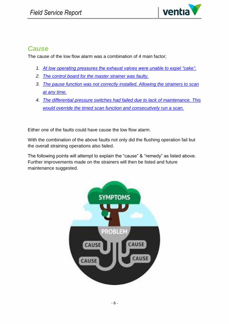
Cause The cause of the low flow alarm was a combination of 4 main factor;
1. At low operating pressures the exhaust valves were unable to expel “cake”.
2. The control board for the master strainer was faulty.
3. The pause function was not correctly installed. Allowing the strainers to scan
at any time.
4. The differential pressure switches had failed due to lack of maintenance. This
would override the timed scan function and consecutively run a scan.
Either one of the faults could have cause the low flow alarm.
With the combination of the above faults not only did the flushing operation fail but
the overall straining operations also failed.
The following points will attempt to explain the “cause” & “remedy” as listed above.
Further improvements made on the strainers will then be listed and future
maintenance suggested.

Field Service Report
- 7 -
Cause - Low Operating Pressures
The exhaust valves installed were only designed to expel process fluid at a certain
pressure. When air is released from the diaphragm the process fluid must overcome
the piston and seat attached to the diaphragm. See picture below;
Remedy - Low Operating Pressures
The valves were replaced with butterfly actuator valves. This allows effluent to pass
through the valve at any pressure. All the air supply lines were also modified and
now feature isolation for maintenance purposes. See picture below;
Field Service Report
- 8 -
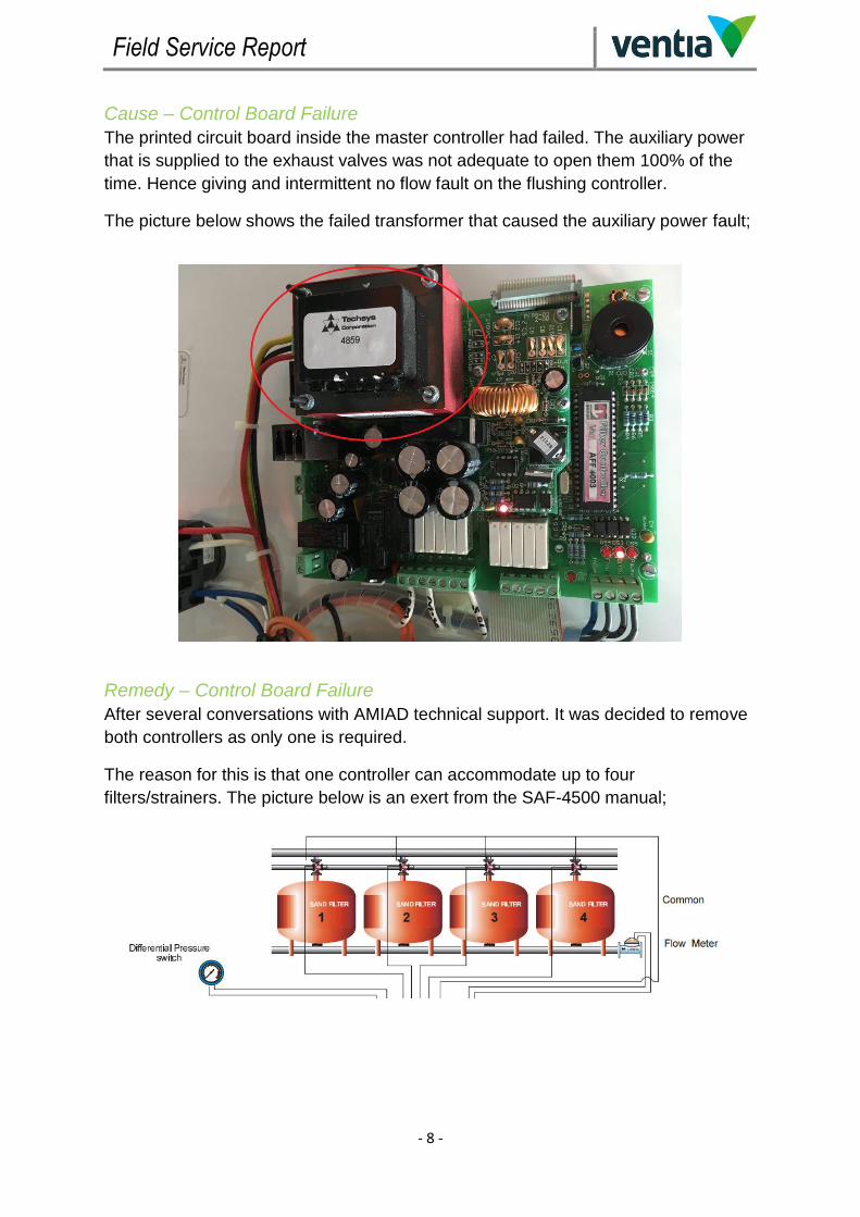
Cause – Control Board Failure
The printed circuit board inside the master controller had failed. The auxiliary power
that is supplied to the exhaust valves was not adequate to open them 100% of the
time. Hence giving and intermittent no flow fault on the flushing controller.
The picture below shows the failed transformer that caused the auxiliary power fault;
Remedy – Control Board Failure
After several conversations with AMIAD technical support. It was decided to remove
both controllers as only one is required.
The reason for this is that one controller can accommodate up to four
filters/strainers. The picture below is an exert from the SAF-4500 manual;
Field Service Report
- 9 -
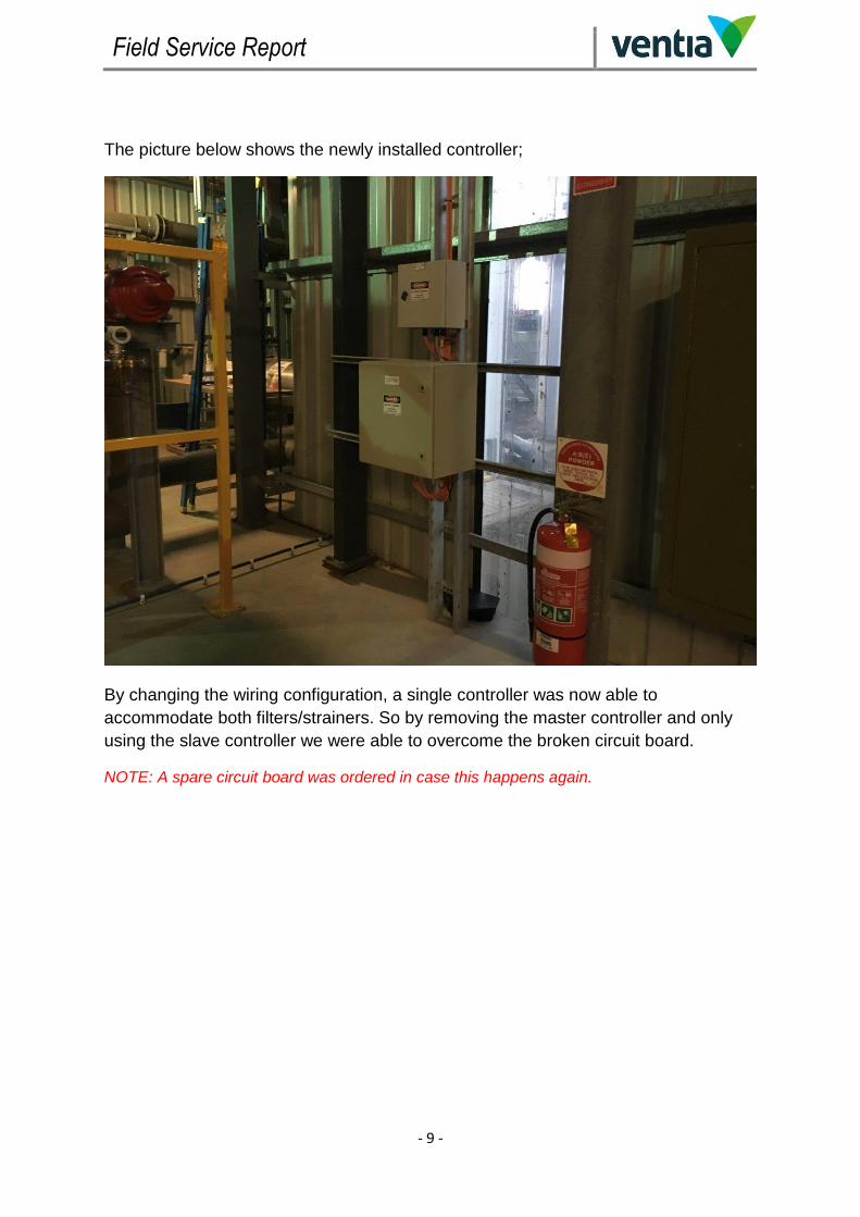
The picture below shows the newly installed controller;
By changing the wiring configuration, a single controller was now able to
accommodate both filters/strainers. So by removing the master controller and only
using the slave controller we were able to overcome the broken circuit board.
NOTE: A spare circuit board was ordered in case this happens again.

Field Service Report
- 10 -
Cause – Pause Function
The pause function that causes the strainers to stop flashing whilst the UF filters are
not operational, was not wired correctly. This meant that the strainers were flushing
on a timed cycle but did not have sufficient operational pressure (feed pumps were
not running). Hence the flashing controller would go into no flow.
Remedy – Pause Function
When the master and slave controllers were merged into one. The opportunity was
taken to correctly wire the pause function.
The picture below shows what the local controller now displaying when the pause is
active;

Field Service Report
- 11 -
Cause – Differential Pressure Switch
The differential pressure switches are located directly on the strainers. They are
designed to measure the differential pressure across the micron filter and force a
flush at a pre-determined pressure (7psi).
Both switches had not been serviced for some time and had failed closed. As a
result the strainers were flushing all the time. The picture below shows the
differential pressure switch;
Remedy – Differential Pressure Switch
Whilst the concept of the pressure switches is necessary. They are very limited in
their functionality. So to increase diagnostics and operational efficiency the
discussion was made install differential pressure transmitters.
These transmitters were installed on both strainers and give real time values of the
differential pressure across the filters. See picture on the next page;

Field Service Report
- 12 -
The existing switches were then decommissioned and the transmitters brought
online. Both of these transmitters can now be viewed and managed from CITEC, see
below;

Field Service Report
- 13 -
The new differential pressure transmitters no longer immediately induce a flush/scan.
The differential set point and alarm delay is now variable via CITEC and once these
set points are reached it will only request that the operator force a flush/scan. See
below;
The example to the right shows a set point of 0.9
kPa and a time delay of 20 seconds.
If the differential pressure in either strainer exceeds
0.9 kPa for longer than 20 seconds, then and a
“WASH REQUIRED” label will appear.
This will not automatically initiate a flush/scan, this
will need to be done by the operator via the “RUN
REQUEST” button.
Any faults associated with the strainers are now also
shown and can be reset via CITEC. See below;

Field Service Report
- 14 -
Maintenance Whilst the upgrades to the strainers were being performed. They also under went
some general maintenance.
1. The internal micron filters were removed and cleaned. Below is the dirty filter;

Field Service Report
- 15 -
2. The course filters on the motor side of the strainers were removed and
cleaned. Below is the dirty filter;

Field Service Report
- 16 -
3. All the rubbers and O-rings were replaced. Below is a crushed rubber seal;
Field Service Report
- 17 -
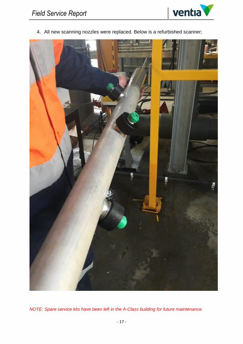
4. All new scanning nozzles were replaced. Below is a refurbished scanner;
NOTE: Spare service kits have been left in the A-Class building for future maintenance.
Field Service Report
- 18 -
Improvements
Regular Maintenance
Upon first impressions of the strainer system it was evident that they have not been
serviced for some time. The overall breakdown of these strainers can directly be
contributed to the lack of maintenance.
The AMIAD SAF-4500 Micro-Strainers are an important part of the A-Class process.
When not properly maintained they can put unnecessary strain on the rest of the
plant.
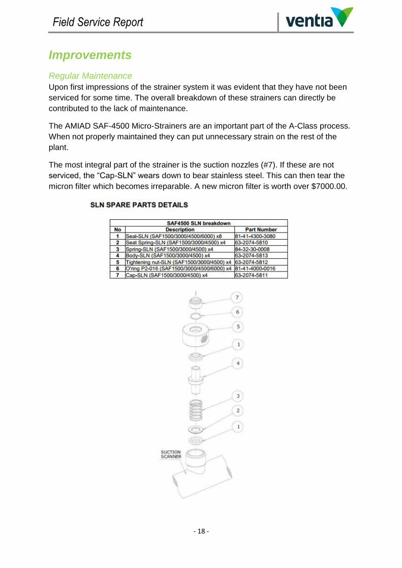
The most integral part of the strainer is the suction nozzles (#7). If these are not
serviced, the “Cap-SLN” wears down to bear stainless steel. This can then tear the
micron filter which becomes irreparable. A new micron filter is worth over $7000.00.

Field Service Report
- 19 -
Inlet Filter
Currently there is no filter before the strainers. There is a course filter of the strainer
but this not very practical for serviceability. See picture below;
An inlet strainer like the “C In-Line” type show below, would be easy to maintain and
access for service. Ideally it would be located between the feed pumps and the
AMIAD SAF-4500. See the link below for more information;
http://www.amiad.com/catalog-in.asp?type1=1&num=96&cat=18

Field Service Report
- 20 -
Conclusion The AMIAD SAF-4500 Micro-Strainer is now fully operational.
Before being upgraded, it had been neglected and was inefficient. By installing more
diagnostics and remote operations the strainers should now operate as intended.
The ability to now see the differential analog value will now enable the operator to
assess the integrity of the micron filter and request serviceability based on real
figures.
It is crucial that these strainers remain properly maintained or it will result in
additional operational costs.
References The following documentation is attached to this PDF;
ABB 2600T Differential Pressure Transmitter Manual
AMIAD SAF-4500 Manual
ABB 2600T Calibration Certificates

Field Service Report
- 21 -
Enquiries Should you need any clarification on this document or if you wish to discuss a site
upgrade please contact myself or Anthony Crowther.
David List Mob: 0408 006 344 Email: [email protected] Anthony Crowther Mob: 0439 619 314 Email: [email protected]

Model M26Manifold line for 266 pressure transmitters
Data Sheet DS/M26-EN Rev. E
Comprehensive wetted material portfolio
Accessories availableBolts and brackets allow multiple installations and grant full transmitter support.
Tee bars easily manoeuvrable
2600T Series Pressure TransmittersEngineered solutions for allapplications
Tailored manifold to meet user’s needs
Perfect interface between process and transmitter thanks to the most common connection types.
Colour coded functional identification

2 DS/M26-EN Rev. E | 2600T Series Pressure transmitters Manifold line M26
Model M26Manifold line for 266 pressure transmitters
Functional SpecificationsManifold pressure rating vs. process temperature:Standard PTFE packing and gaskets
PTFE propertiesMechanical propertiesPTFE has good tensile properties different from other plastic materials as it may be used over a wide temperature range from – 250°C to +250°C ( -418°F to +482°F ) . PTFE shows the lowest friction values compared to other plastic materials. Furthermore, being the static friction values almost equal to the dynamic friction values, there is no tendency to seizure within a sliding system situation, and therefore no detachment friction.
Electrical propertiesPTFE has very good electrical properties. Dielectric strength is excellent and remains unchanged even at high temperature, it only decreases depending on the material thickness and on the electrical frequency values. Dielectric constant values and dissipation factor are among the lowest values and remain unchanged even at high temperatures and at a wide frequency range. Good resistance to arc and corona effect.
Other propertiesPTFE surfaces are highly anti adhesive and do not absorb moisture. PTFE is non-toxic and can be used in contact with food. There are some limitations only for some kinds of filled PTFE due to the toxicity of some filling elements ( i.e. heavy metals and its compounds ) .
External agents resistancePTFE is considered inert towards nearly all known chemical elements and it is insoluble in all solvents. It is only attached by elemental alkali metals, and by Chlorine Trifluoride and elemental Fluorine at high temperatures and pressures. Fluorinated hydrocarbons can have a swelling effect on PTFE but it is a reversible situation, while some fluorinated oils, around 300°C ( 5 72°F ) temperature, swell anddissolve PTFE. PTFE is completely untouched by light and atmospheric agents. Its resistance to nuclear radiations is rather low, it is affected by it starting from 105 rad. with a lowering of the tensile properties.
Manifold pressure rating vs. process temperature:optional Graphoil packing and gaskets
Graphoil propertiesMechanical propertiesGraphoil may be used over a wide temperature range from – 250°C to +600°C ( -400°F to +1112°F ) .It features high resistance to corrosion, heat and fire. Graphoil is generally used in high temperature processes where thermal and/or mechanical shocks can occur. It provides an excellent seal even with low torques or irregular flange surfaces.
Other propertiesGraphoil is a packing and gasket material made exclusively from natural graphite flake. Its high degree of chemical compatibility makes Graphoil inert to most chemicals and gases with the exception of strong oxidizing agents.

2600T Series Pressure transmitters Manifold line M26 | DS/M26-EN Rev. E 3
ImportantPlease ask for a supplementary check if your application is close to the limits shown in the above picture (230°C and/or 6000 psi).
Important The maximum working temperature of the whole assembly (manifold and instrument) corresponds to the temperature limit of the pressure transmitter.
Important When the manifold is assembled to a 2600T pressure trans-mitter with NACE compliance A4-50 Stainless Steel bolts (available on request), please note that the maximum working pressure is limited to 210 bar (3045 psi).
Standard supplied partsM26 manifolds are always supplied with:- PTFE gaskets for transmitter connection (for flanged models)- 1 or 2 Plugs 1/4“ NPT-M (according to the selected model)- Carbon Steel bolts- Certificate of compliance with the order EN10204-2.1- Inspection certificate EN 10204-3.1 of manifold body only.
(*) The mounting bracket kit contains:bracket, U-bolts, cap screws, nuts, lock washers, spacers and assembling instruction.
Physical Specification
(Refer to ordering information sheets for options related to specific model or versions code)MaterialsBody, bonnet and nutAISI 316 L ss; Hastelloy C-276™; Monel 400™; Inconel 625Mounting bracket (*)Zinc plated carbon steel; AISI 316 L ss.Gaskets PTFE, other available on request.BoltsZinc plated carbon steel; AISI 316 ss bolts and nuts Class A4–50 per UNI 7323 (ISO 3506), in compliance with NACE MR0175 Class II (as option).
Made in Italy

4 DS/M26-EN Rev. E | 2600T Series Pressure transmitters Manifold line M26
Model M26Manifold line for 266 pressure transmitters
Two-valve manifold configurations(Refer to ordering information sheets for options related to specific model or versions code)
M26.P.A.S.2.V. - Two-valve bar stock manifold. Threaded connections
Inlet (process connection) 1/2 in. - 14 NPT male
Outlet (transmitter side) 1/2 in. - 14 NPT female
Drain 1/4 in. - 18 NPT female
Packing PTFE
Rating 690 bar (69 MPa, 10000 psi)
Included accessory 1 plug 1/4 in. - 18 NPT male
M26.P.A.S.2.V. - Two-valve bar stock manifold. Threaded connections
Inlet (process connection) 1/2 in. - 14 NPT female
Outlet (transmitter side) 1/2 in. - 14 NPT male
Drain 1/4 in. - 18 NPT female
Packing PTFE
Rating 690 bar (69 MPa, 10000 psi)
Included accessory 1 plug 1/4 in. - 18 NPT male
M26.P.A.S.2.V. - Two-valve bar stock manifold. Threaded connections
Inlet (process connection) 1/2 in. - 14 NPT male
Outlet (transmitter side) 1/2 in. - 14 NPT male
Drain 1/4 in. - 18 NPT female
Packing PTFE
Rating 690 bar (69 MPa, 10000 psi)
Included accessory 1 plug 1/4 in. - 18 NPT male
Note:
For details about the correct codification of each single model of manifold,
please refer to the ordering information at the end of this document.

2600T Series Pressure transmitters Manifold line M26 | DS/M26-EN Rev. E 5
M26.P.A.S.2.V. - Two-valve bar stock manifold. Threaded connections
Inlet (process connection) 1/2 in. - 14 NPT female
Outlet (transmitter side) 1/2 in. - 14 NPT female
Drain 1/4 in. - 18 NPT female
Packing PTFE
Rating 690 bar (69 MPa, 10000 psi)
Included accessory 1 plug 1/4 in. - 18 NPT male
M26.D.A.S.2.V. - Two-valve bar stock manifold for DP Style transmitters
Body configuration For standard flanges transmitters
Inlet (process connection) 1/2 in. - 14 NPT female
Outlet (transmitter side) Flanged according IEC61518/B
Drain 1/4 in. - 18 NPT female
Packing PTFE
Rating 413.3 bar (41.37 MPa, 6000 psi)
Included accessories
1 plug 1/4 in. - 18 NPT male
1 PTFE gasket for transmitter flanged
side (IEC61518/B)
2 Carbon steel screws 7/16 in. UNF
(length 2 in.)
M26.D.A.V.2.V. - Two-valve bar stock manifold for DP Style transmitters
Body configuration For vertical flanges transmitters
Inlet (process connection) 1/2 in. - 14 NPT female
Outlet (transmitter side) Flanged according IEC61518/B
Drain 1/4 in. - 18 NPT female
Packing PTFE
Rating 413.3 bar (41.37 MPa, 6000 psi)
Included accessories
1 plug 1/4 in. - 18 NPT male
1 PTFE gasket for transmitter flanged
side (IEC61518/B)
2 Carbon steel screws 7/16 in. UNF
(length 1 3/4 in.)
Note:
For details about the correct codification of each single model of manifold,
please refer to the ordering information at the end of this document.

6 DS/M26-EN Rev. E | 2600T Series Pressure transmitters Manifold line M26
Model M26Manifold line for 266 pressure transmitters
Three-valve manifold configurations(Refer to ordering information sheets for options related to specific model or versions code)
M26.D.A.S.3.V. - Three-valve bar stock manifold for DP transmitters
Body configuration For standard flanges transmitters
Inlet (process connection) 1/2 in. - 14 NPT female
Outlet (transmitter side) Flanged according IEC61518/B
Drain 1/4 in. - 18 NPT female
Packing PTFE
Rating 413.3 bar (41.37 MPa, 6000 psi)
Included accessories
2 plug 1/4 in. - 18 NPT male
2 PTFE gasket for transmitter flanged
side (IEC61518/B)
4 Carbon steel screws 7/16 in. UNF
(length 2 in.)
M26.D.A.V.3.V. - Three-valve bar stock manifold for DP transmitters
Body configuration For vertical flanges transmitters
Inlet (process connection) 1/2 in. - 14 NPT female
Outlet (transmitter side) Flanged according IEC61518/B
Drain 1/4 in. - 18 NPT female
Packing PTFE
Rating 413.3 bar (41.37 MPa, 6000 psi)
Included accessories
2 plug 1/4 in. - 18 NPT male
2 PTFE gasket for transmitter flanged
side (IEC61518/B)
4 Carbon steel screws 7/16 in. UNF
(length 1 3/4 in.)
Note:
For details about the correct codification of each single model of manifold,
please refer to the ordering information at the end of this document.

2600T Series Pressure transmitters Manifold line M26 | DS/M26-EN Rev. E 7
Five-valve manifold configurations(Refer to ordering information sheets for options related to specific model or versions code)
M26.D.A.S.5.V. - Five-valve bar stock manifold for DP transmitters
Body configuration For standard flanges transmitters
Inlet (process connection) 1/2 in. - 14 NPT female
Outlet (transmitter side) Flanged according IEC61518/B
Drain 1/4 in. - 18 NPT female
Packing PTFE
Rating 413.3 bar (41.37 MPa, 6000 psi)
Included accessories
2 plug 1/4 in. - 18 NPT male
2 PTFE gasket for transmitter flanged
side (IEC61518/B)
4 Carbon steel screws 7/16 in. UNF
(length 2 in.)
M26.D.A.V.5.V. - Five-valve bar stock manifold for DP transmitters
Body configuration For vertical flanges transmitters
Inlet (process connection) 1/2 in. - 14 NPT female
Outlet (transmitter side) Flanged according IEC61518/B
Drain 1/4 in. - 18 NPT female
Packing PTFE
Rating 413.3 bar (41.37 MPa, 6000 psi)
Included accessories
2 plug 1/4 in. - 18 NPT male
2 PTFE gasket for transmitter flanged
side (IEC61518/B)
4 Carbon steel screws 7/16 in. UNF
(length 1 3/4 in.)
Note:
For details about the correct codification of each single model of manifold,
please refer to the ordering information at the end of this document.

8 DS/M26-EN Rev. E | 2600T Series Pressure transmitters Manifold line M26
Model M26Manifold line for 266 pressure transmitters
M26.P.A.S.2.V. Two-valve manifold with threaded connection (1/2 in. - 14 NPT male inlet and 1/2 in. - 14 NPT female outlet); pressure rating 690 bar (69 MPa, 10000 psi)
M26.P.A.S.2.V. Two-valve manifold with threaded connection (1/2 in. - 14 NPT female inlet and 1/2 in. - 14 NPT male outlet); pressure rating 690 bar (69 MPa, 10000 psi)
22 (0.87)
148 (5.83)
VE
NT.
ISO
LATE
FULLY OPEN
57 (2
.24)
30 (1
.18)
1/4" NPT-F DRAIN
30 (1.18)
IN
120
(4.7
2)
OU
T
30 (1.18)
56 (2
.20)
30 (1
.18)
22 (0.87)
Ø5,5 (0.21)
148 (5.83)
VE
NT.
ISO
LATE
FULLY OPEN
120
(4.7
2)
OU
TIN
1/4" NPT-F DRAIN
MOUNTING DIMENSIONS (not for construction unless certified) – dimensions in mm

2600T Series Pressure transmitters Manifold line M26 | DS/M26-EN Rev. E 9
M26.P.A.S.2.V. Two-valve manifold with threaded connection (1/2 in. - 14 NPT male inlet and outlet); pressure rating 690 bar (69 MPa, 10000 psi)
Ø5,5 (0.22)
120 (4.73)
34 (1.34)30 (1.18)
143 (5.63)
22 (0.87)
FULLY OPEN
1/4" NPT-F DRAIN
ISOLATE
VENT
30 (1.18)
OU
TIN

10 DS/M26-EN Rev. E | 2600T Series Pressure transmitters Manifold line M26
Model M26Manifold line for 266 pressure transmitters
M26.P.A.S.2.V. Two-valve manifold with threaded connection (1/2 in. - 14 NPT female inlet and female outlet); pressure rating 690 bar (69 MPa, 10000 psi)
VE
NT.
50 (1.97)
1/4" NPT-F DRAININ
OU
T
60 (2
.36)
168 (6.61)
30 (1
.18)
VE
NT.
ISO
LATE
ISO
LATE
FULLY OPEN
N°2 FIXING HOLES Ø7 (0.27)

2600T Series Pressure transmitters Manifold line M26 | DS/M26-EN Rev. E 11
M26.D.A.V.2.V. Two-valve manifold for vertical flanges DP Style transmitters; 1/2 in. - 14 NPT female threaded inlet and flanged outlet according to IEC 61518/B (transmitter side); pressure rating 413.7 bar (41.37 MPa, 6000 psi).
2x Ø12 (0.47)
1/4" NPT-F DRAIN
INLET SIDE1/2" NPT-F
INSTRUMENT SIDE(IEC 61518/B)
ISOLATE
VENT
32 (1.30)
108,
2 (4
.26)
20 (0.79)
75 (2.95)
131,4 (5.17)FULLY OPEN
FULL
Y O
PE
N
10 (0
.39)
42,5 (1.77)

12 DS/M26-EN Rev. E | 2600T Series Pressure transmitters Manifold line M26
Model M26Manifold line for 266 pressure transmitters
M26.D.A.S.2.V. Two-valve manifold for standard flanges DP Style transmitters; 1/2 in. - 14 NPT female threaded inlet and flanged outlet according to IEC 61518/B (transmitter side); pressure rating 413.7 bar (41.37 MPa, 6000 psi).
60 (2
.36) 89
(3.5
0)
40 (1.57)
71,4 (2.81)
41,3
(1.6
3)
18 (0.71)
75 (2.95)
131,4 (5.17)
35 (1.38)
11 (0
.43)
16 (0
.63)
61 (2.40)
M10 x 1.5
1/4" NPT-F DRAIN
2X Ø12 (0.47)
INSTRUMENT SIDE(IEC 61518/B)
FULLY OPENFULLY OPEN
INLET SIDE1/2" NPT-F
VENT
ISOLATE
FULL
Y O
PE
N

2600T Series Pressure transmitters Manifold line M26 | DS/M26-EN Rev. E 13
M26.D.A.S.3.V. Three-valve manifold for standard flanges DP Style transmitters; 1/2 in. - 14 NPT female threaded inlet and flanged outlet according to IEC 61518/B (transmitter side); pressure rating 413.7 bar (41.37 MPa, 6000 psi).
105 (4.13)
217,8 (8.57)
54 (2.13)
41,3
(1.6
3)
4x Ø
12 (0
.47)
72,9 (2.87)
40 (1.57)
60 (2
.36)
88,1
(3.4
7)
INSTRUMENT SIDE(IEC 61518/B)
INLET SIDE2x 1/2" NPT-F
FULL
Y O
PE
N
FULLY OPEN
20 (0
.79)
30 (1.18)84 (3.30)
16 (0
.63)
EQUALISE
ISOLATEISOLATE
2x 1/4" NPT-F DRAIN2x M10x1.5

14 DS/M26-EN Rev. E | 2600T Series Pressure transmitters Manifold line M26
Model M26Manifold line for 266 pressure transmitters
M26.D.A.V.3.V. Three-valve manifold for vertical flanges DP Style transmitters; 1/2 in. - 14 NPT female threaded inlet and flanged outlet according to IEC 61518/B (transmitter side); pressure rating 413.7 bar (41.37 MPa, 6000 psi).
80 (3.15)
16 (0
.63)
41,3
(1.6
3)
54 (2.13)
150 (5.90)
258 (9.96)
Ø12
(0.4
7)
85 (3.35)
10 (0
.39)
2x 1/4" NPT-F DRAIN
ISOLATEISOLATE
EQUALISE
2x M10x1.5
70 (2
.75)
32 (1.26)
126,
3 (4
.97)
FULL
Y O
PE
N
INSTRUMENT SIDE(IEC 61518/B)
INLET SIDE
2x 1/2" NPT-F

2600T Series Pressure transmitters Manifold line M26 | DS/M26-EN Rev. E 15
M26.D.A.S.5.V. Five-valve manifold for standard flanges DP Style transmitters; 1/2 in. - 14 NPT female threaded inlet and flanged outlet according to IEC 61518/B (transmitter side); pressure rating 413.7 bar (41.37 MPa, 6000 psi).
Ø12
(0.4
7)
54 (2.13)
155 (6.10)
267,8 (10.54)
41,3
(1.6
3)
40 (1.57)
71,4 (2.81)
109
(4.2
9)
60 (2
.36)
30 (1.18)
115 (4.53)
30 (1
.18)
24 (0
.94)
INLET SIDE
2x 1/2" NPT-F
INSTRUMENT SIDE
(IEC 61518/B)
EQUALISE
ISOLATEISOLATE
2x 1/4" NPT-F DRAIN
2x M10 FIXING HOLES
VENTVENT

16 DS/M26-EN Rev. E | 2600T Series Pressure transmitters Manifold line M26
Model M26Manifold line for 266 pressure transmitters
M26.D.A.V.5.V. Five-valve manifold for vertical flanges DP Style transmitters; 1/2 in. - 14 NPT female threaded inlet and flanged outlet according to IEC 61518/B (transmitter side); pressure rating 413.7 bar (41.37 MPa, 6000 psi).
41,3
(1.6
3)
54 (2.13)
150 (5.90)
262,8 (10.35)
80 (3.15)
16 (0
.63)
70 (2
.75)12
6,3
(4.9
8)
32 (1.26)INSTRUMENT SIDE
(IEC 61518/B)
INLET SIDE
2x 1/2" NPT-F
VENT
ISOLATE
EQUALISE
ISOLATE
VENT
FULL
Y O
PE
N
85 (3.35) 2x 1/4" NPT-F DRAIN
FULLY OPEN
2x M10x1.5

2600T Series Pressure transmitters Manifold line M26 | DS/M26-EN Rev. E 17
Gauge or absolute pressure transmitter (266HSH, 266GSx, 266ASx) on its mounting bracket with M26.P.A.S.2.V. (1/2 in. - 14 NPT male inlet and 1/2 in. - 14 NPT female outlet threaded connection).
Gauge or absolute pressure transmitter (266HSH, 266GSx, 266ASx) on its mounting bracket with M26.P.A.S.2.V. (1/2 in. - 14 NPT female inlet and 1/2 in. - 14 NPT male outlet threaded connection).
116 (4.57)
72 (2.83)
62 (2
.44)28
2 (1
1.08
)
224
(8.8
2)
105 (4.12)
18 (0.71)Space for
cover removal
58 (2.28)
9 (0.35)91 (3.58)
162
(6.3
7)
143 (5.63)36
(1.4
2)
49 (1.93)
1/2" - 14 NPT
162
(6.3
5)
18 (0.71)Space forcover removal
78 (3.04)55 (2.16)
116 (4.57)
72 (2.83)
62 (2
.44)28
2 (1
1.08
)
224
(8.8
2)
105 (4.12)
18 (0.71)Space for
cover removal
58 (2.28)
9 (0.35)91 (3.58)
148 (5.83)
36 (1
.42)
49 (1.93)
179
(7.0
2)
1/2" - 14 NPT
142
(5.5
7)
Space forcover removal
18 (0.71)78 (3.04)55 (2.16)

18 DS/M26-EN Rev. E | 2600T Series Pressure transmitters Manifold line M26
Model M26Manifold line for 266 pressure transmitters
Gauge or absolute pressure transmitter (266HSH, 266GSx, 266ASx) on its mounting bracket with M26.P.A.S.2.V. (1/2 in. - 14 NPT male inlet and outlet threaded connection).
Gauge or absolute pressure transmitter (266HSH, 266GSx, 266ASx) on its mounting bracket with M26.P.A.S.2.V. (1/2 in. - 14 NPT female inlet and outlet threaded connection).
116 (4.57)
72 (2.83)
62 (2
.44)28
2 (1
1.08
)
224
(8.8
2)
105 (4.12)
18 (0.71)Space for
cover removal
58 (2.28)
9 (0.35)91 (3.58)
162
(6.3
7)
143 (5.63)36
(1.4
2)
1/2" - 14 NPT
162
(6.3
5)
Space forcover removal
18 (0.71)78 (3.04)55 (2.16)
116 (4.57)
72 (2.83)
62 (2
.44)
282
(11.
08)
102
(3.9
9)
105 (4.12)
18 (0.71)Space for
cover removal
58 (2.28)
9 (0.35)91 (3.58)
162
(6.3
7)
168 (6.61)
36 (1
.42)
1/2" - 14 NPT
18 (0.71)Space forcover removal
78 (3.04)55 (2.16)

2600T Series Pressure transmitters Manifold line M26 | DS/M26-EN Rev. E 19
Pressure transmitter DP-Style (266PSH, 266VSH, 266RSx) on manifold bracket with M26.D.A.S.2.V. (1/2 in. - 14 NPT female threaded inlet and flanged outlet according to IEC 61518/B)
Pressure transmitter DP-Style (266PSH, 266VSH, 266RSx) with vertical flanges on manifold bracket with M26.D.A.V.2.V. (1/2 in. - 14 NPT female threaded inlet and flanged outlet according to IEC 61518/B)
18 (0.71)91 (3.58) Space for
cover removal
158
(6.2
3)17
9 (7
.02)
58 (2.28)
9 (0.35)
88 (3.45)20
8 (8
.19)
18 (0.71)Space forcover removal
78 (3.04)55 (2.16)
88 (3.43)
104 (4.06)
71 (2.77)
18 (0.71)91 (3.58) Space for
cover removal
92
(3.6
3)
24
3 (9
.57
)
50 (1.97)
48
(1.8
9)
58 (2.28)
9 (0.35)
118 (4.63)
18 (0.71)Space forcover removal
78 (3.04)55 (2.16)
144 (5.68)
217 (8.55)

20 DS/M26-EN Rev. E | 2600T Series Pressure transmitters Manifold line M26
Model M26Manifold line for 266 pressure transmitters
Differential pressure transmitter (266DSH, 266MSH) on manifold bracket with M26.D.A.S.3.V. (1/2 in. - 14 NPT female threaded inlet and flanged outlet according to IEC 61518/B)
18 (0.71)91 (3.58) Space for
cover removal
158
(6.2
3)17
9 (7
.02)
54 (2.13)
58 (2.28)
9 (0.35)
217.8 (8.57)20
8 (8
.19)
18 (0.71)Space forcover removal
78 (3.04)55 (2.16)
88 (3.43)
11 (0
.43)
142 (5.59) 104 (4.06)
71 (2.77)
Differential pressure transmitter (266DSH, 266MSH) on manifold bracket with M26.D.A.V.3.V. (1/2 in. - 14 NPT female threaded inlet and flanged outlet according to IEC 61518/B)
18 (0.71) 18 (0.71)91 (3.58) Space for
cover removal
92 (3
.63)
229
(9.0
1)
258 (9.96)
62 (2
.45)
78 (3.04)58 (2.28)
9 (0.35) Space forcover removal
55 (2.16)
144 (5.68)236 (9.28)

2600T Series Pressure transmitters Manifold line M26 | DS/M26-EN Rev. E 21
Differential pressure transmitter (266DSH, 266MSH) on manifold bracket with M26.D.A.S.5.V. (1/2 in. - 14 NPT female threaded inlet and flanged outlet according to IEC 61518/B)
Differential pressure transmitter (266DSH, 266MSH) on manifold bracket with M26.D.A.V.5.V. (1/2 in. - 14 NPT female threaded inlet and flanged outlet according to IEC 61518/B)
18 (0.71)91 (3.58) Space for
cover removal
158
(6.2
3)17
9 (7
.02)
54 (2.13)
58 (2.28)
9 (0.35)
267.8 (10.54)
208
(8.1
9)
18 (0.71)Space forcover removal
78 (3.04)55 (2.16)
88 (3.43)
11 (0
.43)
104 (4.06)
71 (2.77)
18 (0.71) 18 (0.71)91 (3.58) Space for
cover removalSpace forcover removal
92 (3
.63)
229
(9.0
1)
262.8 (10.35)
62 (2
.45)
78 (3.04)55 (2.16)
58 (2.28)
9 (0.35)
144 (5.68)
236 (9.28)

22 DS/M26-EN Rev. E | 2600T Series Pressure transmitters Manifold line M26
Model M26Manifold line for 266 pressure transmitters
Ordering information
BASIC ORDERING INFORMATION model M26 manifold Select one character or set of characters from each category and specify complete catalogue number.Refer to additional ordering information and specify one or more codes for each transmitter if additional options are required.BASE MODEL - 1st to 3rd characters M 2 6 X X X X X X X X X X
Manifold model for 266 Pressure Transmitters
Design - 4th character
Manifold for DP Style transmitters D
Manifold for P Style transmitters P
Revision - 5th character
Revision A A
Body configuration - 6th character
Standard construction S
For vertical-flange transmitter (Note 1) V
Valves - 7th character
Two-valve manifold 2
Three-valve manifold (Note 1) 3
Five-valve manifold (Note 1) 5
Valve Type - 8th character
Standard V
Material (wetted parts) - 9th character
AISI 316L ss NACE S
Hastelloy C276 NACE H
Monel 400 M
Inconel 625 N
Packing material - 10th character
PTFE P
Graphoil G
Gasket material (wetted parts) - 11th character
None (Note 2) N
PTFE (Notes 1, 6) P
Graphoil (Notes 1, 7) G
Manifold process connection (INLET)- 12th character
Threaded 1/2 in. - 14 NPT-female F
Threaded 1/2 in. - 14 NPT-male (Note 2) M
Manifold transmitter connection (OUTLET)- 13th character
Flanged outlet according to IEC61518/B (Note 1) 1
Threaded 1/2 in. - 14 NPT-female (Note 2) F
Threaded 1/2 in. - 14 NPT-male (Note 2) M

2600T Series Pressure transmitters Manifold line M26 | DS/M26-EN Rev. E 23
M26 X X X X X X X X X X X X X X X X X
Rating - 14th character
413.7 bar (41.37 MPa, 6000 psi) (Note 1) 6
690 bar (69 MPa, 10000 psi) (Note 2) 1
Transmitter fixing bolts - 15th characters
(Note 2) N
(Note 1) C
None
Carbon Steel
Stainless Steel NACE compliant (MWP= 21 MPa, 210 bar, 3045 psi) (Note 1) S
Bracket kit - 16th character
None N
Carbon Steel bracket kit for pipe mounting (Notes 1, 3) C
Stainless Steel bracket kit for pipe mounting (Notes 1, 4) S
Material traceability - 17th character
Inspection certificate EN 10204–3.1 of manifold body only (Note 5) 1
Inspection certificate EN 10204–3.1 of process wetted parts 2
Note 1: Not available with design code PNote 2: Not available with design code DNote 3: Not available with bolts code SNote 4: Not available with bolts code C Note 5: Not available with material (wetted parts) codes H, M, snd NNote 6: Not available with packing material code GNote 7: Not available with packing material code P
Manifold made in Italy by SAMI Instruments Srl
Standard delivery items (can be differently specified by ordering code)– PTFE gaskets for transmitter connection (for flanged models)– 1 or 2 Plugs 1/4“ NPT-M (according to the selected manifold model)– Carbon Steel bolts– Certificate of compliance with the order EN10204-2.1– Inspection certificate EN 10204-3.1 of manifold body only.
NACE CONFORMITY IS ACCORDING TO Recommendations PER MR0175 2003 / ISO 15156-3 FOR AISI 316L, HASTELLOY C-276, INCONEL 625 AND MONEL 400
M26 manifolds are in compliance with ASME B31.1 - Power Piping.
Hastelloy C-276TM is a Cabot Corporation trademarkMonel 400TM is an International Nickel Co. trademark

DS
/M26
-EN
Rev
. E
05
.201
5
Contact us
NoteWe reserve the right to make technical changes or modify the contents of this document without prior notice. With regard to purchase orders, the agreedparticulars shall prevail. ABB does not accept any responsibility whatsoever for potential errors or possible lack of information in this document.
We reserve all rights in this document and in the subject matter and illustrations contained therein. Any reproduction, disclosure to third parties or utilization of its contents - in whole or in parts – is forbidden without prior written consent of ABB.
Copyright© 2015 ABB All rights reserved
3KXP7200007R1001
ABB Ltd.Process AutomationHoward Road, St. NeotsCambridgeshire, PE19 8EUUKTel: +44 (0)1480 475321Fax: +44 (0)1480 217948
ABB Inc.Process Automation125 E. County Line RoadWarminster, PA 18974USA Tel: +1 215 674 6000Fax: +1 215 674 7183
ABB Automation Products GmbHProcess AutomationSchillerstr. 7232425 MindenGermany Tel: +49 551 905-534Fax: +49 551 905-555
ABB S.p.A.Process AutomationVia Statale 11322016 Lenno (CO),ItalyTel: +39 0344 58111Fax: +39 0344 56278
www.abb.com
Sales
Service

______________________________________________________________________________________
__________________________________________________________________________________ SAF4500 IO&M Manual (SLN) Rev 4 1
AMIAD Automatic Filters
"SAF-4500" FILTER Cat. Number 03-2
Installation, Operation and Maintenance
Instructions
Amiad Water Systems 138 Northcorp Boulevard Broadmeadows Vic. 3047 Ph. (61) 3 9358 5800, or
1300 426 423 Fax. (61) 3 9358 5888
Email: [email protected]
Ref. 95-046-330-005-Aust/03.2006R4
Serial Number: _____________________ Order Number: _____________________ Catalogue Number: _________________ Filtration Degree : ___________________ Tested By : _________________________
Special Notes : ______________________ __________________________________________________

______________________________________________________________________________________
__________________________________________________________________________________ SAF4500 IO&M Manual (SLN) Rev 4 2
TABLE OF CONTENTS
Technical specifications .................................................................... 3 Safety instructions ............................................................................ 4 Dimensional and recommended installation drawing ......................... 5 Description and filter operation ....................................................... 6, 7 Control System........................................................................... 8 - 13 Circuit Diagrams ...............................................................................14 Installation .................................................................................. 15, 16 Start Up & First Operation .......................................................... 17, 18 Controller settings & Operational Parameters Record ......................19 Maintenance .............................................................................. 20-25 Disassembling and reassembling ............................................... 25, 26 Parts schedule .................................................................................27 Parts drawing - Section 1 .................................................................28 Parts drawing - Section 2 .................................................................29 Parts drawing - Section 3 .................................................................30 SLN Parts schedule .........................................................................31 Notes ...............................................................................................32
With any inquiry please quote Filter Serial Number, located on the filter housing.

______________________________________________________________________________________
__________________________________________________________________________________ SAF4500 IO&M Manual (SLN) Rev 4 3
TECHNICAL SPECIFICATIONS General Maximum flow rate 250 m3/h 1100 USgpm Consult manufacturer for optimum
flow depending on filtration degree & water quality.
Min. working pressure 1.5 bar 21 psi or lower if pressure is increased for flushing
Max. working pressure 10 bar 150 psi 16 bar = 240 psi upon request
Filter area 4,500 cm2 700in2
Inlet/Outlet diameter 100,150, 200 mm
4", 6", 8" Flange standards as per request.
Filter housing 250 mm 10" Epoxy-coated steel or other on request.
Max. working temperature
600C 1400F
Weight 100 mm = 150 Kg 150 mm = 156 Kg 200 mm = 165 Kg
4" = 330 lb. 6" = 344 lb. 8" = 364 lb.
Flushing data Exhaust valve 50 mm 2"
Flushing cycle time 20 seconds 20 seconds
Wasted water per cycle 83 liter 22 gallon at 2 bar = 30 psi Minimum flow for flushing
15 m3/h 66 USgpm at 2 bar = 30 psi
Control and electricity Control voltage 24V AC (12V or 24V DC upon request)
Electric motor 1/4 HP 50 / 60 Hz, 35 / 42 Gear output R.P.M. Rated operation Voltage
3 phase 220 / 380 / 440 V, 50 / 60 Hz Single phase 110 / 220 V, 50 / 60 Hz DC 12V or 24V (upon request)
Current consumption 0.6 Amp. (with 3 phase 380 / 440 V) Construction materials Filter Housing and Lid Epoxy-coated carbon steel 37-2 (Stainless Steel 316 available on request).
Screens Stainless Steel 316
Cleaning mechanism Stainless Steel 316, POM
Exhaust valve Epoxy-coated cast iron, Natural Rubber
Seals Synthetic Rubber
Control Aluminum, Brass, Stainless Steel, PVC Standard filtration degrees Stainless Steel Weavewire Screen
micron 500 300 200 130 100 80 50 25 10
mm 0.5 0.3 0.2 0.13 0.1 0.08 0.05 0.02 0.01
mesh 30 50 75 120 155 200 300 450 600

______________________________________________________________________________________
__________________________________________________________________________________ SAF4500 IO&M Manual (SLN) Rev 4 4
SAFETY INSTRUCTIONS General
1. Prior to installation or work on the filter, please read the installation and operation instructions, carefully.
2. While working on the filter, please observe all conventional safety instructions in order to avoid danger to the workers, the public or nearby property.
3. Please note, the filters may flush automatically, without prior warning. 4. No changes or modification to the equipment is permitted without express authorization from
the manufacturer or its representative. Installation
1. Install the filter according to the instructions in this manual. 2. Leave enough clearance for easy access to all components and safe maintenance operations. 3. Electric wiring should be performed by an authorized electrician only, using standardized and
approved components. 4. Install a main power cut-off switch close to the control panel. 5. If the control panel cannot be seen from the filter(s), a power cut-off switch should be installed
near each filter unit. 6. The filter should be installed in a manner that avoids splashing water on the electrical
components or the control panel. 7. Extra safety devices should be installed on hot water applications to avoid scalding.
Operation, control and maintenance
1. Disconnect the filter from power supply before maintenance or working on the unit(s). 2. Release pressure from the unit(s) before loosening or unscrewing bolts. 3. Try to keep the work area as dry as possible to prevent mishaps, possible electrocution or
damage to the equipment caused by moisture. 4. Always open and close valves slowly and gradually. 5. Remove grease and fat material residues in order to avoid slipping. 6. Always re-assemble the protective covers of the drive mechanism. 7. When using a high pressure water or steam cleaner to clean a screen manually, follow the
device’s operation and safety instructions carefully. 8. When using acid or other chemical agents to clean a screen manually, follow the appropriate
safety instructions provided by the chemical manufacturer. Use of lifting equipment
1. While using lifting equipment, make sure that the filter or the lifted part is chained securely and in a safe manner.
2. Avoid working below lifted equipment. 3. Ware a safety helmet while working around lifted equipment.

______________________________________________________________________________________
__________________________________________________________________________________ SAF4500 IO&M Manual (SLN) Rev 4 5
DIMENSIONAL DRAWING AND RECOMMENDED INSTALLATION Key: Dimensions in mm (inches) 1. 4" SAF 4500 2. 4" inlet butterfly valve 3. 4" by-pass valve 4. 4" downstream valve 5. 4" non-return check valve * Minimum distance required for maintenance.

______________________________________________________________________________________
__________________________________________________________________________________ SAF4500 IO&M Manual (SLN) Rev 4 6
DESCRIPTION OF FILTER OPERATION
Filtering process: The SAF 4500 is a sophisticated yet easy-to-operate automatic filter, with a self-cleaning mechanism driven by an electric motor. The SAF 4500 is designed to work with various types of screens in filtration degrees from 10 to 500 micron, and is available in 4", 6" and 8" inlet/outlet diameter. The water enters through the inlet pipe into the coarse screen from outside in, and through the fine screen from inside out. The "filtration cake" accumulates on the fine screen surface and creates head loss to develop. The coarse screen is designed to protect the cleaning mechanism from large dirt particles. Usually, it does not accumulate large quantities of suspended solids and is not cleaned automatically.
Self-cleaning process:
The SAF 4500 filter controller automatically initiates the self-cleaning process when either the pressure differential across the screen reaches a pre-set value, or the flush timer reaches its preset timed interval. Cleaning of the filters screen element is carried out by the scanner, which rotates in a traversing spiral movement to cover the full screen area. The only passage for the water to exit the filter is into the scanner nozzle and out through the exhaust valve – an induced flow into the scanners nozzles (due to the difference in pressure from the filter housing to atmospheric pressure at the termination of the drain pipe –the “water will take the least path of resistance” and flow out to the drain pipe), shall remove the filter cake from the screen with a quantity of water, and expel it out through the exhaust valve and drain pipe, to effect the cleaning of the screen element. The filter scanners rotational direction is provided by forward and reversing contactors for the drive motor, which drives through a reduction gearbox that is connected to the scanner via a threaded shaft with fixed bushing, providing the linear movement between two limit switches, (monitored and controlled via the filter controller). The exhaust valve is activated for the duration of the filters cleaning cycle by a pilot solenoid plumbed to the top of the exhaust valve. During the self-cleaning process, which takes approximately 20 seconds, filtered water continues to flow downstream of the filter, (the filter cleaning is conducted “on-line”). The operational pressure of the feed water to the filters during a cleaning cycle, with due respect for the filtration degree, type of debris encountered by the screen, the type of exhaust valve, and any friction or head losses in the drain pipe, all influence the velocity of the induced flow into the scanner nozzles, and consequently the filters ability to clean its screen. Should the feed pressure be too low and/or the losses in the drain pipe be too great, problematic cleaning the filter(s) screen may result. Consequently if the operational pressure is above 500 kPa it is common to throttle the drainage flow during a cleaning cycle, (as the induced velocity into the scanner nozzles can be excessive resulting in noisy operation & wasted water per cleaning cycle, and possibly reduce the life of the screen element). Please consult your local Amiad office for design assistance or guidance as so required.

______________________________________________________________________________________
__________________________________________________________________________________ SAF4500 IO&M Manual (SLN) Rev 4 7
Different modes of filtration:
The filter may be found in one of the following modes: 1. Filtering mode: Water is passing through the filter and the pressure differential across the unit is
below the PD set point. (The controller is in a monitoring mode and between the pre-programmed time initiated cleaning cycle).
2. Flushing mode: The filter has entered into a cleaning cycle. The filter still filters the water during
the self cleaning cycle, (unless special valving or operating conditions exist). The exhaust valve will be open and the drive motor operating)
3. Malfunction mode: The controller has identified an alarm/fault condition. These are typically;
a). “Filter Stalled” – meaning that the PD switch has remained in a closed state for 15 minutes continuous. During “Filter stalled” mode the self-cleaning operation will continue until the fault is corrected. Press “Enter” to clear the “filter stalled” display.
b). “Xflush” – meaning the pre-programmed maximum number of flushes/cleaning cycles per
hour has been exceeded. c). “Limit Switch Flt” – meaning either both limit switches are activated simultaneously or a
limit switch has not been reached within a certain timeframe from when the other limit switch has been left.
d). “Mtr Rotation Flt” – meaning on initial start up of the filter the motor wrong limit switch
was first activated. The motor polarity needs to be reversed. The controller needs to see the correct limit switch on initial start-up.
e). “Flush Motor Flt” – meaning the overload for the drive motor has been activated. This
fault condition will only occur if an auxiliary switch is fitted to the motor O/L ( this is an option to the “Standard“ controller trim).
A changeover contact is provided in the controller, which may be used as an output for either when the filter is conducting a cleaning cycle, or as an alarm/fault output. Programming of the controller for this parameter will depict what function the changeover contact is being utilized for. If it is programmed for any fault/alarm, the contact will switch position whenever any of the above conditions occur.
Initiation of self-cleaning: The filter will enter the self-cleaning process as a result of any of the following causes: 1. A signal from the Pressure Differential Switch (PDS) - The PDS which is situated on the filter
body, sends an electric signal when the pressure differential across the screen reaches the pre-set value (usually 0.5 bar). The control board registers the signal and operates the flushing process according to its program.
2. Manually pressing the ”ENTER” & "UP" buttons simultaneously when in the “TEST MODE”
screen of the controller. (Refer to the attached controller manual to familiarize with the controller operation. ).
3. The integral TIMER of the control board initiates the self-cleaning process when the pre-
programmed “flush cycle time” has expired, independent of the pressure differential across the filter. The timer resets after every flushing cycle regardless of its initiation.

______________________________________________________________________________________
__________________________________________________________________________________ SAF4500 IO&M Manual (SLN) Rev 4 8
CONTROL SYSTEM Controller Brief: The SAF & EBS series of filter controller is designed to monitor and control the following equipment incorporated with the on the filter assembly;
1. Three Phase drive motor (typically 0.18/0.25/0.37 kW) via reversing contactors (motor is driving a reduction gearbox which in turn drives a lead screw with a static bushing - back and forth between two limit switches), which only operates during a flushing cycle.
2. 2 x limit switches (wired NC) per filter -provide feedback to govern the length of travel of the lead screw (One "scan" = travelling from one limit switch to the other, which equates to the scanner covering the complete screen area.
3. Pilot solenoid (typically 24VAC), energises to open the exhaust valve during a flush cycle (default valve is a hydraulically controlled diaphragm exhaust valve, but may also be a pneumatic actuated valve, or electric with a customised controller).
4. Pressure Differential (PD) Switch (wired NO) - monitors the differential pressure across the filter and when the set point is made (closed contact) and held for a prescribed period of time, shall initiate a flushing cycle.
Our "Standard" build controller, (for the SAF & EBS series of filters), is a circuit board with EPROM chip control platform c/w 2 line digital display and 3 button keypad interface, and the following gear tray mounted hardware;
• Switchable fuse (power supply for circuit boards), • 2 x contactors (reversing of motor direction), • Motor O/L c/w auxiliary output, & • Numbered terminals.
A Mains isolator is fitted into the side of the powder coated IP55 rated "Standard" enclosure and requires a Three Phase + Neutral & Earth power supply (Single phase or other power supply options available on request).
Standard Inputs;
• 2 x Limit switches (wired NC) per filter • PD switch, (wired NO) • Remote Flush: A voltage free pulse signal is required to initiate (on a closed contact will
reset a Fault/alarm condition (if possible), and when open contact will start the flush cycle), Time delay between closed & open contact to be typically 50 to 100 ms.
• Pause: Volt free Closed contact will prevent subsequent flush cycles • Flow: Volt free Closed contact will prevent subsequent flush cycles,. May be used for
pressurised/gravity systems to prevent flushing unless a flow condition exists (flow switch), or for non-pressurised systems to prevent flush cycles if the pump is not running, (Pressure Switch)
• Motor overload (from the auxiliary contact mounted to motor O/L- wired internally to the expansion circuit board).
Note: All the above inputs are 12VDC powered from circuit board across their respective set of terminals.

______________________________________________________________________________________
__________________________________________________________________________________ SAF4500 IO&M Manual (SLN) Rev 4 9
Standard Outputs:
• Motor Contactor up signal (internally wired) • Motor contactor down signal (internally wired) • 24VAC exhaust valve pilot solenoid (active when filter flushing) • 24VAC "Master" solenoid (active when filter flushing), (if multiple filters this output
remains active from the start of the first to the end of the last filters flush cycle)- may be used at your discretion or for a downstream valve to reposition during a flush cycle etc.
• Voltage Free Alarm (Volt Free: may be wired NO or NC) • Filter flushing: Volt free, NO contact (closed contact when flushing- one or multiple
filters).
Controller Display & Key-Pad; The keypad and display screen provides, operator feedback and interfacing with the controller.
The 2 line digital screen is backlit in SAF/EBS controllers and the key-pad, (Up-Enter-Down), enables moving up and down to the various menu screens, (as tabled below), and activating/acknowledging/setting/resetting of the various operational parameters. Navigate through the menu screens by pressing the “Up” or “Down” keys.
Installation by qualified electrician only
MODEL
FILTER CONTROLLER
TWO LINE DIGITAL DISPLAY

______________________________________________________________________________________
__________________________________________________________________________________ SAF4500 IO&M Manual (SLN) Rev 4 10
To edit the value of the menu item press the “ENTER” key and either the “DOWN” or “UP” key depending on the value required. Tip : Push and hold the “Enter” Key, then push either up or down to make the required change(s), (holding the keys in the pressed condition will continue change the parameters – the longer held the faster the rate of change).
Display screens;
Status Screen No.
Screen description Notes
1 Next Flush
When next flush is scheduled to occur (timed in minutes).
This is also the status information screen which provide message information to advise the operator the status of the filter(s). Fault and alarm messages are displayed every 6 or so seconds for a few seconds (flashed up on the display) if they exist.
2 Flush Counter Counts flush cycles (one count per cycle whether one or multiple filters) May be reset to zero.
3 Test Mode Manual test Cycle initiation: (Enter & Up Arrow)
4 Commission Mode
Commission mode “OFF” is default, (Enter & Up Arrow) changes to Commission mode “ON” - allowing access to controller operational parameters. Will revert to Commission mode “OFF” if keypads not touched for few minutes.
Notes;
NAVIGATION TIP: You may leave the controller on any of the first four screens – however it is good practise to leave the display on screen 1 – all the filter status and alarm/fault messaging is viewed via this screen. You may move within these screens at any time whether the filter(s) are flushing or not.
SAVING SETTINGS TO THE NON-VOLITILE MEMORY: To save programmable parameter settings to the non-volatile menu you must push the “down” arrow all the way (to the bottom screen which advises when next flush is due etc.) after any changes to parameters settings. If not when the controller is powered down or looses power it will revert to the previous settings when next powered.
Installation by qualified electrician only
MODEL
FILTER CONTROLLER

______________________________________________________________________________________
__________________________________________________________________________________ SAF4500 IO&M Manual (SLN) Rev 4 11
RESETTING FAULT/ALARM CONDITIONS;
Pushing the “Enter “ button, or providing a remote flush pulse input signal to the controller shall clear a fault/alarm condition, and its respective display message. Do not push enter until you have viewed the screen for at least 7 to 10 seconds (as the flashed up nature of the messaging will be missed, and if Enter is pressed there is no history information to advise what the condition was). The information provided on the screen will assist greatly in the time to trouble shoot a given issue).
RESETTING THE CONTROLLER (TO FACTORY DEFAULT SETTINGS):
Under certain conditions it may be required to “Reset” the controller, (Typically if the controller is behaving unusually or if particular outputs not operating or intermittent – such issues may occur if the controller is subject to excessive voltage/current spikes or possibly conflicting I/O’s terminations). Instruction: 1. Switch the power supply to the controller “OFF”, 2. wait for the controller to fully power down., 3. Press, and hold, the secret menu button – then switch the power supply to the controller
“ON” 4. Wait 2 to 3 seconds then release the secret menu button (the factory default parameters
have now been reset to the controller) 5. Enter “Commissioning ON” and re-program all the appropriate parameters for your given
application. 6. Save the re-programmed parameters to the non-volatile memory. 7. Initiate a manual flush cycle and closely monitor the filter and controller operation.

______________________________________________________________________________________
__________________________________________________________________________________ SAF4500 IO&M Manual (SLN) Rev 4 12
Controller Typical & Default settings; (Only accessible if entered into “COMMISSION ON” menu)
Parameter SAF/EBS Typical settings
Notes Factory default settings
Flush Duration 1 Scan
Meaning: travels from one limit switch to the other. (multiple scans are only required for special application)
2 Scans
Flush cycle: 120 min
Time based flush cycle count down timer (resets after each flush cycle) If set to Zero will revert to PD flushing only
60 min
Flush dwell time: 0 sec Delay time between flushing
filter 1 & 2. 0 sec
No. of Filters: 1
Upto 4 units per expansion circuit board may be operated (multiple expansion boards are linked for >4 filters)
1
Sol. Coil: 24VAC Exhaust valve pilot solenoid voltage 12VDC
Sol. Type: Standard
continuous current (latching is available only for 12VDC solenoids & available in 2 or 3 wire options)
Standard
Max. flushes / h: 20
If exceeds this value will provide fault output for Excess flushes
20
Filter type: Sol + Mtr Scan
Defines type of filter being utilized. (Solenoid only, Sol + Mtr Timed, are the other setting options)
Sol + Mtr Scan
Output: Any Fault/Alarm
Voltage Free (can be wired NO or NC)
Filter Flushing
Flow sensing: None
Options are available to configure a water meter input to enable volumetric flushing initiation and or excessive flowrate output/alarm.
None
Flow Units Only available if “Flow sensing” parameter selected N/A
Flow Scale Only available if “Flow sensing” parameter selected N/A
Flush after Only available if “Flow sensing” parameter selected N/A
Design Flowrate Only available if “Flow sensing” parameter selected N/A

______________________________________________________________________________________
__________________________________________________________________________________ SAF4500 IO&M Manual (SLN) Rev 4 13
Hidden menu parameters
TO ACCESS HIDDEN MENU ITEMS: When in “COMMISSIONING ON” press and hold the secret menu button for at least 3 consecutive seconds, scroll the menu screens down and you will find there are three additional screens below the “Next Flush” Screen.
Parameter SAF/EBS Typical settings
Notes Factory default settings
Diff. pressure delay:
5 sec Time PD switch must provide closed contact state to initiate a flush cycle
5 sec
Limit switch delay: 3 sec
Delay from energising solenoid till motor starts, for a given flush cycle, & delay between changing motor direction if multiple scans programmed. Note: If drive motor is Single phase, this delay must be set to at least 10 seconds.
3 sec
Flow averaging 10
Only utilized if configuring the controller with a water meter volumetric pulse(reed switch) input – “flow sensing” selected (which also provides addition screens to allow volumetric flushing initiation & excess flowrate alarm functionality)
10
This timer adjusts the delay time between the Differential Pressure switch activating and the initiation of a flush cycle. If the differential pressure switch opens while the timer is counting down then the timer will reset and start from the beginning. This timer is relevant to the operation of the SAF and EBS filters. It controls the delay time between he reversing of the flushing motor when the limit switch has been activated. The reason for its existence is to reduce the possibility of a single phase motor failing to reverse
when the contactors reverse. This can occur if the capacitor attached to the flushing motor has not fully discharged. Always be sure to visually check the activation of the limit switches when operating a single phase SAF or EBS on commissioning. Have access to an emergency stop switch is it is seen that the motor has not reversed.
The flow averaging is used to maintain accuracy when the flow pulses are staggered by an amount greater than one second. The filter controller accepts flow pulses from a flow meter and calculates flow rate based on the number of pulses per second. If the flow
pulses have a frequency of greater than one second then the accuracy of the displayed reading will be variable. To counter this we average the calculation of flow rate based on the figure put into this menu. e.g. If the flow averaging was set to 10 then we calculate the flow rate based on the last 10 readings and average all 10 readings and display this average. This method produces a flow rate on the screen that is much more relevant to the actual flow rate.
Diff Pressure delay
5
Limit switch delay
3
Flow averaging
10

______________________________________________________________________________________
__________________________________________________________________________________ SAF4500 IO&M Manual (SLN) Rev 4 14
CONTROLLER CIRCUIT DIAGRAMS

______________________________________________________________________________________
__________________________________________________________________________________ SAF4500 IO&M Manual (SLN) Rev 4 15
INSTALLATION (Mechanical) Design recommendations:
1. Often, flow increases and pressure drop dramatically during fill-up of a water system. In this case, a pressure-sustaining valve installed downstream of the filter will ensure the minimum required pressure for the filter and a controlled filling-up of the line.
2. If constant water flow is required even during maintenance, it is recommended that a manual
or automatic by-pass be installed. Isolating valves will be used to isolate each filter unit. 3. In applications where the water quality periodically worsens, it is possible to operate an
emergency flush program. In order to do so, an automatic Down Stream valve must be installed. For details, please consult the manufacturer. In periods of high loading the flow should be reduced through the filter if the filter cannot remove the debris faster than it is being trapped on the screen.
Installation instructions:
1. Install the filter horizontally in a manner that will allow convenient access and enough space to dismantle the filter for maintenance purposes. The filter may be installed on the top of the pipe, under-slung, or out to either side of the feed pipe.
2. Check the direction of flow according to the arrows marked on the filter housing.
3. It is recommended to install a mechanical non-return valve downstream of the filter.
4. The exhaust line (minimum 2" diameter) should be designed so that it creates minimal
resistance to flow of 25 m3/h.
5. If the system is designed to operate with working pressure higher than 5 bar, it is recommended that a manual throttling valve will be installed on the exhaust line, in order to enable regulation of the flushing flow rate.
6. The user should arrange suitable lighting at the area of the filter to enable good visibility and
safe maintenance.
7. The user should arrange suitable platforms and safety barriers to enable easy access to the filter without climbing on pipes and other equipment.
IMPORTANT !! Prevent static back-pressure or reverse flow through the filter. Install a manual or a hydraulic valve downstream of the filter.

______________________________________________________________________________________
__________________________________________________________________________________ SAF4500 IO&M Manual (SLN) Rev 4 16
INSTALLATION (Electrical) Electric wiring
General: Locate and mount the controller, preferably within view of the filter. If mounted outdoors ensure the controller is rated accordingly, or make provision for protection to the controller. Power connection to the controller: Connect a three-phase power supply + Neutral + Earth to the controller. Earth the controller. Power connection to the motor: Connect the drive unit to the control panel by means of a 4 x 2.5 mm2 (12 or 14 AWG) wire in flex-conduct. Use a long enough cable to allow removal of the drive unit and placing it near the filter for maintenance, without having to disconnect it from the cable. (the installation requires to meet or exceeds local or national electrical codes/standards). Field wiring: Connect between the control junction box and the control board by means of 6 x 1.5 mm2 (16 AWG) wire in flex-conduct ( 2 x limit switches, 1x 24VAC Solenoid, 1 x DP Switch). In electrical “noising” environments the DP switch should be connected with shielded cable.

______________________________________________________________________________________
__________________________________________________________________________________ SAF4500 IO&M Manual (SLN) Rev 4 17
START-UP AND FIRST OPERATION
1. Make sure all the electric wiring is correct, according to the preceding wiring drawings.
2. Remove the cover over the lead screw and limit switch sling such that you can monitor the filters movements.
3. Switch the main isolator on and check that the O/L and switchable fuse are also in the “on”
position. The filter is supplied from our warehouse with the limit switch striker plate set in between the two limit switches.
4. Check the programmed parameters of the controller are correctly for your application before
conducting a cleaning cycle, (refer to controller manual for details). Once these parameters are confirmed correct initiate a manual self-cleaning cycle. To manually activate a flushing cycle press the “enter” and “up” push buttons simultaneously when in the “TEST MODE” screen of the filter controller, (refer to the attached controller manual if unsure how to navigate through the controller interface screen ). Make sure all flushing stages occur as described in the filter description chapter of this manual. Note: The filter can dry run without damage, (providing your system does not operate a pump during the cleaning cycle as an added special requirement), and it is preferred to conduct dry testing of the filter logic prior to testing with flow & pressure.
5. The suction scanner shaft should rotate and move down to the lower limit switch. The motor
should stop when the limit switch plate reaches the lower limit switch. If the unit pauses on the bottom limit switch, (or has traveled to the Top limit switch) , and then rotates in the opposite direction, to move off the limit switch, and then stops - there is a problem with the motor rotational direction or wiring to the limit switches. On the first operation the controller logic is designed that it moves to the lower limit switch first. The fault condition “Motor Rotation Fault” will be displayed if the filter behaves as described. Check the limit switches are wired correctly & prove that they are providing feedback to the controller, if they are correct the motor wiring phases should be swapped to reverse the motor direction, if not correct the limit switch wiring and conduct another manual cycle.

______________________________________________________________________________________
__________________________________________________________________________________ SAF4500 IO&M Manual (SLN) Rev 4 18
6. Once the first filter cycle is successfully tested and you are comfortable with the controller
operation, open the inlet valve to the filter, while the outlet valve remains closed or with an open by-pass valve (this will keep the flow in the filter at a minimum), and operate a flushing cycle under pressure conditions.
7. Make sure the exhaust valve opens and all stages of the flushing cycle are carried out
successfully.
8. Attend to leakage, if any.
9. Use the manometer valve (plumbed to the Low Pressure sense port of the filter housing) to simulate a DP switch self cleaning cycle initiation. By blocking the Low pressure sense port and bleeding the LP tube to atmosphere, via the manometer valve. The PDS shall close its contacts when the DP reaches 50 kPad, which is being monitored by the controller, and it shall initiate a cleaning sequence after the pre-set 5 to 10 second time period of the DP switch contacts is registered. Re-position the manometer valve once the DP switch induced cleaning cycle has been successfully accomplished.
10. Gradually open the outlet valve and/or close the by-pass valve. Operate the filter at the
designed hydraulic conditions.
11. Check the “Flush cycle time” is set to an appropriate setting, (Default setting is every hour, but can be altered for each and every application).
12. Reset the flush counter and monitor the filter cleaning cycles over the first few hours & days.
Ensure the filter is recovering after its cleaning cycles and investigate any fault conditions.
13. Record the clean filter differential pressure and record the flush counter reading with date & time, this information can be used as a benchmark and checked every few days or week to provide feedback to the loading the filter is being subject to.

______________________________________________________________________________________
__________________________________________________________________________________ SAF4500 IO&M Manual (SLN) Rev 4 19
CONTROLLER SETTINGS
& OPERATIONAL PARAMETERS RECORD
Parameter Default Update/Notes
Flush Duration 1 Scan Meaning: travels from one limit switch to the other.
Flush cycle: 60 min Timed flush cycle (resets
after each flush cycle) Flush dwell time: 0 sec Delay time between flushing
filter 1 & 2. No. of Filters: 1 Sol. Coil: 24VAC Sol. Type: Standard (continuous current)
Max. flushes / h: 20
If exceeds this value will provide fault output for Excess flushes
Filter type: Sol + Mtr Scan Output: Any Fault/Alarm Flow sensing: None
Diff. pressure delay: 5 sec
Time PD switch needs to be held prior to PD flush initiation
Limit switch delay: 3 sec
Delay from energising solenoid till motor starts, for a given flush cycle, & delay between changing motor direction if multiple scans programmed
Special Notes: 1. To save programmable parameter settings to the non-volatile menu you must push the
“down” arrow all the way (to the bottom screen which advises when next flush is due etc.) 2. Diff Delay & Limit switch Delay parameters are found in a hidden menu (please consult
Amiad office for more details)
Record the system operational parameters, as a benchmark for future troubleshooting activities.
System operational parameters Inlet Pressure Outlet pressure Differential pressure (with clean screen) System flowrate Feed pressure when cleaning PD switch set-point 50 kPad (7 psid) default
Please copy this page and place inside the common filter controller.

______________________________________________________________________________________
__________________________________________________________________________________ SAF4500 IO&M Manual (SLN) Rev 4 20
MAINTENANCE General inspection
1. Push the down arrow of the key for the filter controller to view the status screen of the controllers digital display, (if it is not already on this screen) – watch the screen for at least 10 seconds to verify if any alarm/fault messages are displayed, (every 6 to 7 seconds the display will provide text indicating an alarm or fault condition- should one exist).
2. Check for any signs of leakage from the drive shaft seal – If necessary, replace the Sealing flange Internal O-Ring (item 9.1)
3. Check that the limit switch striker plate is sitting on either of the limit switches of each filter (assuming the filters are not conducting a cleaning cycle).
4. In order to check the proper operation of the filters, isolate and vent the low-pressure sense pipe to the common pressure differential switch, for a period of at least 5 seconds. This will initiate a PD initiated self-cleaning cycle: Check that the exhaust valve opens, that the scanner traverses between the limit switches, and when it reaches a limit switch - verify that the exhaust valve closes, for each filter. (Subsequently a manual cleaning cycle initiation via the controller operator panel may be conducted.)
5. Check the Pressure differential across the filter by utilizing the 3-way selector valve and the 63mm dial pressure gauge to take readings of the inlet and outlet pressure of each filter, (deducting the inlet pressure from the outlet pressure shall provide the differential pressure across the filter).
Weekly maintenance:
1. Perform a general inspection as described above. 2. Clean the 3/4" filter connected to the exhaust solenoid. (Close the 3/4" valve and activate a
flush cycle in order to release pressure and then unscrew the filter bowl).
3. Check that there is grease on the drive shaft, and drive bushing. Add grease if necessary.
4. Check for any leakage from the scanner shaft. If necessary, replace the sealing nut internal O-Ring (9.1)
5. Inspect the exterior filter coating for damage or deterioration – touch coat as & when
required

______________________________________________________________________________________
__________________________________________________________________________________ SAF4500 IO&M Manual (SLN) Rev 4 21
Annual maintenance (Major inspection & service)
SLN Note: We recommend the filter(s) to be serviced and inspected annually. If the filter is fitted with the SLN scanner, more frequent inspection and servicing may be required to replace the nozzle caps. SLN fitted filters need to be monitored regularly initially to establish the typical number of flush cycles or timing required before replacing the nozzle caps. Failure to replace the caps, when worn, may cause screen damage in some circumstances.
1. Carry out weekly maintenance as instructed above. 2. Isolate the filter electrically and mechanically.
3. Dissemble the filter, clean & inspect all parts for wear or deterioration and replace seals or
parts as so required.
4. Lubricate the appropriate items (“per lubrication Notes” below) as the filter is re-assembled.
5. Inspect the filter exterior coating and remedy as and when required.
6. Remove PD sense ports and tubes and clean & inspect prior to re-assembly
7. Check the junction box terminals for signs of moisture or poor connections (clean/replace and re-terminate as so required).
8. Re-assemble the filter and thoroughly check the operation of the controller and its various
cleaning initiation options (manual, PD, time based, and remote flush initiation) and the various Input and outputs options.
9. Dry and wet test the filter.
Maintenance prior to long term shutdown (end of sea son): The following must be done if the filter will not be in operation for longer than a month.
1. Perform a flush cycle (If possible, with a closed downstream valve).
2. Release pressure from the filter.
3. Power down the unit when the drive shaft is half way and none of the limit switches is pressed.
4. Disconnect the power supply to the control board.
5. Grease the drive shaft and the drive bushing.
6. Clean the 3/4" control filter.
7. Clean the coarse screen. Maintenance after long term shutdown:
1. Connect the control board to the power supply.
2. Check proper operation of the filter, especially noting proper rotation.
3. Grease the drive shaft and the drive bushing.
4. If necessary, change the Sealing nut internal O-Ring.

______________________________________________________________________________________
__________________________________________________________________________________ SAF4500 IO&M Manual (SLN) Rev 4 22
Cleaning the coarse screen:
1. Close the filter inlet and outlet valves.
2. Release pressure from the filter by performing a flush cycle.
3. Remove the service lid (4.8) by disconnecting the bolts (4.10) from the nuts (4.12)
4. Clean the coarse screen: a. To remove large particles insert your hand into the coarse screen area. b. To remove fine particles and organic matter rinse the screen. Afterwards, partially open
the inlet valve and let water flow out.
5. Reverse assemble the service lid, slowly open the inlet valve to re-charge the filter, check for leaks & remedy as required, then slowly open the discharge valve.
Changing the sealing nut internal O-ring:
1. Close the inlet valve to the filter and release the pressure. 2. Remove the cover (23) from the drive shaft housing (8) by unscrewing the wing nuts (23.6). 3. If the Suction Scanner is in the outer position, operate a flush cycle and bring it to the inner
position. 4. Remove the Split pin (22.2) and pull out the connecting pin (22.1). 5. Operate a flush cycle. 6. Power down the unit when the drive shaft is half way through its cycle. The drive shaft is
now separated from the Suction Scanner. 7. Unscrew the sealing nut (9). 8. Remove the used internal O-ring (9.1) and clean the O-ring seat. 9. Insert a new O-ring (9.1) 10. Apply some grease on the external O-ring and on the shaft. 11. Tighten the sealing nut (9). 12. Re-connect the drive shaft to the suction scanner shaft. 13. Operate the control board and open the filter inlet valve.

______________________________________________________________________________________
__________________________________________________________________________________ SAF4500 IO&M Manual (SLN) Rev 4 23
Limit Switch Setting Instruction;
It is imperative that the limit switches are correc tly set and secured for the reliable operation of the filter. The following instruction is to be followed to make the appropriate settings for the SAF series of filters.
SAF Limit switches
The limit switch position must be such that: after the switch is has “made” its contact, (from each respective end), there must be at least ¾ of a full turn of travel remaining without the scanner nozzle ending its travel. Instruction to check and or set limit switches ;
1. Remove the gearbox & Motor from the filter, and use a wrench on the drive shaft to rotate the scanner assembly, when checking limit switch settings. Use a multi-meter across the limit switch terminals, or input terminals to the controller (set to the “Continuity” setting) to verify the contact point of each respective limit switch.
2. Wind the scanner shaft slowly upto one of the limit switches, once the switch has confirmed it contact has been made, stop rotating. Check the position of the wrench, then continue to rotate the scanner (it must be able to rotate for at least ¾ of a full revolution before making contact with any filter internals).
3. Adjust the switch position if required to allow the extra rotation of the scanner after the contact is made, and re-check the contact and extra rotation to verify.
4. Repeat the check and adjustment on the other limit switch.
5. Once settings have been verified as correct, ensure the limit switch sling & Limit switches are securely fastened.
6. Rotate the scanner position such that the striker plate is within the two limit switches and not resting on either (typically the “midway” position).
7. Re-install the gearbox and motor
8. Switch the power to the controller and initiate a cleaning cycle to reset the filter to sit on one of the limit switches.
9. Initiate another cycle to verify the both limit switch operate correctly.
Inner switch Outer switch
Striker Plate

______________________________________________________________________________________
__________________________________________________________________________________ SAF4500 IO&M Manual (SLN) Rev 4 24
Lubrication details;
Motor (#12.1): “Sealed for life” bearings – no lubrication required. Hollow shaft Gearbox (#12.2): 0.2 L capacity of ISO 320 viscosity synthetic oil, (eg. Shell Tivela S
320). The gearbox has one single oil plug. Subject to the frequency of flushing, it is not likely in need of an oil change for at least 5 years. Anti-seize to be cleaned off & re-applied on annual inspection & maintenance
Lead screw (#18): Non-oxidizing grease - applied monthly & on annual inspection &
maintenance.
Drive shaft seal (#9.1): Silicon grease to be applied to the scanner drive shaft O’ring Seal (9.1), and to the sealing section of the scanner drive shaft (2.2).
Screen seals (#3.1): Apply a smear of silicon grease to the seals for its contact to the filter
body & lid only - whenever removed for maintenance/inspection or replaced.
Scanner Bearing internal seals (#1.3 & #7.3): Apply a smear of silicon grease to the internal O’ring of the scanner
bearings (filter lid, and flushing chamber locations) & the mating scanner pipe sections in contact with the respective bearing O’ring. Frequency: whenever removed for maintenance/inspection.
Silicon grease: 50mL tube of Silicon grease, Amiad P/No. 84-84-10-1035 Lead screw lubricant: 100mL tube of non-melting grease (EBS/SAF threaded shaft lubricant) P/No. 84-33-00-0001

______________________________________________________________________________________
__________________________________________________________________________________ SAF4500 IO&M Manual (SLN) Rev 4 25
DISMANTLING AND ASSEMBLING THE FILTER COMPONENTS Prior to opening the filter perform a flush cycle by holding the “enter” button in and simultaneously pressing the “up” push button once when in the “TEST MODE” screen of the filter controller. Fine screen: Dismantling:
1. Close the filter inlet and outlet valves and release the pressure. 2. Release the lid bolts (1.5) from their nuts and remove the lid (1). 3. Pull the screen (3) out of the filter housing. 4. Remove the screen seals (3.1) from the screen.
Assembly: 1. Put the screen seals (3.1) on the screen edges (3). 2. Insert the screen into the filter housing (4) while the support legs point upwards. After
pushing the screen all the way in, rotate the screen so the legs will support it and lead it to its position.
3. Clean and apply some grease on the suction scanner pipe and on the o-ring of the lower bearing (1.3).
4. Assemble the lid on the filter housing. Make sure the screen and seal are correctly positioned in the lid seat.
5. Tighten the bolts (1.5) in a controlled and balanced method. The bolts seats of the lid should touch the bolts seats of the filter housing.
6. Open the filter inlet and outlet valves and operate the control board. 7. Check proper operation of the filter.
Suction scanner: Dismantling:
1. Begin the dismantling procedure as per 1-4 in the chapter "dismantling the fine screen". 2. Remove the cover from the drive shaft housing (23) by unscrewing the wing nuts (23.6). 3. Remove the Split pin (22.2) and pull out the connecting pin (22.1). 4. Pull the suction scanner (2) in a spiral movement out of the filter housing. 5. Unscrew the sealing nut (9).
Assembly:
1. Apply some grease on the smooth side of the suction scanner (2) and insert it into the screen (3). Make sure the scanner (2) passes through the flushing chamber (7). When the suction scanner shaft appears from its port, apply some grease on it and tighten the sealing nut (9).
2. Insert the suction scanner shaft (2.2) into the drive shaft (22). Make sure the holes in the above shafts are parallel.
3. Insert the connecting pin (22.1) to the parallel hole of the suction scanner shaft (2.2) and the drive shaft (22) and lock it with the split pin (22.2).

______________________________________________________________________________________
__________________________________________________________________________________ SAF4500 IO&M Manual (SLN) Rev 4 26
Drive shaft housing and coarse screen: Dismantling:
1. Close the inlet and outlet valves of the filter and release pressure. 2. Disconnect power supply from the control board. 3. Dismantle the suction scanner and fine screen as described previously. 4. Pull out the plug from the solenoid coil (15). 5. Remove the limit switch sling (10) from the drive shaft housing by unscrewing the bolts
(10.1). Carefully put the limit switch sling near the filter to avoid any damage to the electrical wires.
6. Disconnect the tube (16.4) from the solenoid valve (15) and from connector (16.3). 7. Disconnect the drain pipe from the exhaust valve. 8. Remove the drive shaft cover by unscrewing wing nuts (23.6) 9. Remove the drive unit (12) from the drive shaft housing (8) by unscrewing the nuts (12.7)
from the bolts (12.3). By doing so the drive shaft key (13) will be pulled out. 10. Dismantle the drive shaft housing (8) from the flushing chamber flange (7) by unscrewing
the bolts (7.5). 11. Remove the rest of the flange bolts and pull out the flushing chamber assembly which
includes: flushing camber (7), coarse screen (6), screens adapter 5) and screens adapter seal (5.1).
Assembly:
1. Place the coarse screen (6) in its seat in the flushing chamber. 2. Place the screens adapter (5) on the flushing chamber and the coarse screen. 3. Attach the screens adapter seal (5.1) to its place with its flat side, using some grease (as
adhesive material). 4. Attach the flushing chamber o-ring (4.1) to its place using some grease (as adhesive
material). 5. Apply some grease on the o-ring of the upper bearing (7.2). 6. Insert the flushing chamber assembly into its place. Use the centering pin (4.2) to locate the
flange in its position. 7. Tighten the flange to the filter housing with the side bolts only (7.5). 8. Apply some grease on the o-rings (9.1 & 9.2) of the shaft sealing nut (9) and tighten to its
place. 9. Install the drive shaft housing, using the rest of the flange bolts (7.5). 10. Insert the suction scanner (2) and the fine screen (3) as described previously. 11. Connect the drive shaft (22) to the scanner shaft using the connecting pin (22.1) and split
pin (22.2). 12. Make sure the drive shaft key (13) is fitted properly in the gear box. Thread the drive shaft
through the drive unit and make sure that the drive shaft groove is adjusted in accordance with the drive shaft key.
13. Connect the drive unit (12) to the drive shaft housing (8) with the bolts (12.3) and tighten them.
14. Connect the pilot tube between the solenoid valve (15) and the control filter connector (16.3).
15. Assemble the limit switch sling (10) in its place and push in the plug of the solenoid coil. 16. Connect the drain pipe to the exhaust valve (14). 17. Operate the control board and make sure the filter is operating properly. 18. Open the inlet and outlet valves and recheck filter operation.
PARTS SCHEDULE (following page…)

______________________________________________________________________________________
NO. DESCRIPTION CAT. NO. 1 Lid (SAF-4500) 53-2071-1100 1.1 Hydraulic seal AM-08 81-41-4300-3050
1.2 Suction scanner bearing (SAF-4500) 63-2081-0013
1.3 O-Ring 60 x 4 81-41-4100-0460 1.4 Locking spring ring 84-32-00-0011 1.5 Bolt M20 x 120 [x4] 85-1112-20-120 1.6 Washer 3/4" [x4] 85-1311-12-000 1.7 Nut M20 [x4] 85-1212-20-000 2 Suction scanner (SAF-4500 SLN) 13-2074-5800 2.1 Suction scanner nozzle (SLN) 53-2074-5804 2.1.1 Spring Loaded Nozzle Cap Ass. 13-2074-5801 2.2 Suction scanner shaft (SAF-4500) 53-2074-5100 2.3 Slotted pin 5 x 50 (St.St.) 84-32-11-0550 2.4 Slotted pin 3 x 30 (St.St.) 84-32-11-0330 3 Weavewire screen (SAF-4500) 13-2083-0XXX 3.1 Hydraulic seal AM-05 81-41-4300-3001 4 Housing (SAF-4500) 13-20XX-11XX 4.1 O-Ring P2-452 81-41-4000-0452 4.2 Centering pin 84-32-11-1030
4.3 Pressure check point - complete (steel) 12-0100-0012
4.4 Washer M6 (St.St.) [x2] 85-2312-06-000 4.5 Nut M6 (St.St.) [x2] 85-2212-06-000 4.6 Instrumentation bracket (SAF) 63-7044-0023 4.7 Bolt M6 x 20 (St.St.) [x2] 85-2112-06-020 4.8 Service port lid (SAF-4500) 54-0202-1111 4.9 Service port lid seal AM-12 81-41-4300-3022 4.10 Bolt M12 x 80 [x3] 85-1112-12-080 4.11 Washer M12 [x3] 85-1312-12-000 4.12 Nut M12 [x3] 85-1212-12-000 5 Screens adaptor 13-2071-0020 5.1 Flushing chamber seal AM-10 81-41-4300-3055 6 Coarse screen (SAF-4500) 53-2074-2020 7 Flushing chamber (SAF-4500) 13-2074-1021 7.1 Locking spring ring 84-32-00-0011
7.2 Suction scanner bearing (SAF-4500) 63-2081-0013
7.3 O-Ring 60 x 4 81-41-4100-0460 7.4 Locking spring ring 84-32-00-0011 7.5 Bolt M20 x 70 [x8] 85-1112-20-070 7.6 Washer 3/4" [x8] 85-1311-12-000 7.7 Washer 3/4" [x8] 85-1311-12-000 7.8 Nut M20 [x8] 85-1212-20-000 8 Drive shaft housing (SAF-4500) 13-2074-1101 8.1 Drive bushing (SAF) 53-3074-1021 8.2 Bolt M6 x 35 (St.St.) [x3] 85-2112-06-035 8.3 Washer M6 (St.St.) [x3] 85-2312-06-000 8.4 Washer M6 (St.St.) [x3] 85-2312-06-000 8.5 Lock nut M6 (St.St.) [x3] 85-2232-06-000 9 Tightening nut 53-2074-0001 9.1 O-Ring 14 x 3 81-41-4100-0014 9.2 O-Ring 24 x 3 81-41-4100-0024 10 Limit switch sling (SAF) 63-3074-2062 10.1 Bolt M6 x 20 (St.St.) [x2] 85-2112-06-020 10.2 Washer M6 (St.St.) [x2] 85-2312-06-000 10.3 Washer M6 (St.St.) [x2] 85-2312-06-000 10.4 Nut M6 (St.St.) [x2] 85-2212-06-000 11 Limit switch "NC" (EBS, SAF) [x2] 82-23-0000-0101 11.1 Bolt M4 x 20 (St.St.) [x4] 85-2123-04-020 11.2 Washer M4 (St.St.) [x4] 85-2312-04-000 11.3 Lock nut M4 (St.St.) [x4] 85-2232-04-000 12 Drive unit (SAF-1500, 3000, 4500) 53-6041-3500 12.1 Motor, 380-480V 50/60 Hz 1/4 HP 82-92-5430-0000 12.2 Worm gear RMI 50, 28:1 (63) 82-93-0000-0135 12.3 Bolt M8 x 40 [x4] 85-1112-08-040 12.4 Washer M8 [x4] 85-1312-08-000 12.5 Washer M8 [x4] 85-1312-08-000 12.6 Spring washer M8 [x4] 85-1322-08-000
NO. DESCRIPTION CAT. NO. 12.7 Nut M8 [x4] 85-1212-08-000 13 Drive shaft key (SAF) 53-3074-1025 14 Hydraulic valve 2" (GAL) 82-31-0023-0000 Hydraulic valve 2" (RAM) 82-31-5020-0000 Hydraulic valve 2" (RAF) 82-31-9230-0000 14.1 Connector 1/4" x 1/4" (Brass) 52-0100-0020 15 Solenoid valve 24V AC, "NO" 82-21-0024-0001
Solenoid valve 24V AC, "NO" (ASCO) 82-21-0024-0010
15.1 L-Connector 5/16" x 1/4" 82-13-0692-0504 15.2 Air-brake tube 8 mm (5/16") 82-13-9100-0505 15.3 Connector 5/16" x 1/4" 82-13-0682-0504 15.4 L-Connector 5/16" x 1/8" 82-13-0692-0502 Connector 5/16" x 1/4" [with Asco] 82-13-0682-0504
16 3/4" Filter (AC), w/o valve, 200 micron
01-0702-1131-8020
16.1 Raccord nut 3/4" 63-0500-1033 16.2 Raccord nipple 1/4" 63-0500-1032 16.3 L-Connector 5/16" x 1/4" 82-13-0692-0504 16.4 Air-brake tube 8 mm (5/16") 82-13-9100-0505 16.5 O-Ring P2-112 81-41-4000-0112
17 L-Connector 3/4"F-M (Galvanized) 83-3225-0073-0000
18 Ball valve 3/4" (Brass) 82-32-0007-1050
19 Pressure differential switch (Midwest)
84-34-10-0003
19.1 Connector 5/16" x 1/8" 82-13-0682-0502 19.2 Connector 5/16" x 1/8" 82-13-0682-0502 19.3 Air-brake tube 8 mm (5/16") 82-13-9100-0505 19.4 L-Connector 5/16" x 1/4" 82-13-0692-0504 19.5 Set screw M6 x 25 (St.St.) [x2] 85-2162-06-025 19.6 Nut M6 (St.St.) [x2] 85-2212-06-000 19.7 Spring washer M6 (St.St.) [x2] 85-2322-06-000 19.8 Washer M6 (St.St.) [x2] 85-2312-06-000 20 Manometer valve 1/4" 53-6041-4500 20.1 L-Connector 5/16" x 1/4" 82-13-0692-0504 20.2 Air-brake tube 8 mm (5/16") 82-13-9100-0505 21 Electrical junction box (SAF) 13-3074-6000
22 Drive shaft (SAF-1500, 3000, 4500) 53-2074-0143
22.1 Connecting pin 53-2074-0144 22.2 Split pin 1.6 x 12 84-31-70-0002 2.3 Limit switch plate (SAF) 63-3074-2061 22.4 Limit switch plate locking ring 84-32-10-0117 23 DS housing cover 53-2074-0020 23.1 Bolt M6 x 60 (St.St.) [x2] 85-2112-06-060 23.2 Washer M6 (St.St.) [x2] 85-2312-06-000 23.3 Washer M6 (St.St.) [x2] 85-2312-06-000 23.4 Nut M6 (St.St.) [x2] 85-2212-06-000 23.5 Washer M6 (St.St.) [x2] 85-2312-06-000 23.6 Wing nut M6 (St.St.) [x2] 85-2242-06-000 24 Drive shaft cover (SAF) 53-3074-0020 24.1 Set screw M8 x 20 (St.St.) [x4] 85-2132-08-020

______________________________________________________________________________________
PARTS DRAWING Section 1

______________________________________________________________________________________
PARTS DRAWING Section 2

______________________________________________________________________________________
PARTS DRAWING Section 3

______________________________________________________________________________________
SLN SPARE PARTS DETAILS
SAF4500 SLN breakdown No Description Part Number 1 Seal-SLN (SAF1500/3000/4500/6000) x8 81-41-4300-3080 2 Seat Spring-SLN (SAF1500/3000/4500) x4 63-2074-5810 3 Spring-SLN (SAF1500/3000/4500) x4 84-32-30-0008 4 Body-SLN (SAF1500/3000/4500) x4 63-2074-5813 5 Tightening nut-SLN (SAF1500/3000/4500) x4 63-2074-5812 6 O'ring P2-016 (SAF1500/3000/4500/6000) x4 81-41-4000-0016 7 Cap-SLN (SAF1500/3000/4500) x4 63-2074-5811

______________________________________________________________________________________
NOTES;

