project design document (pdd) - cdm loan · pdf fileproject design document (pdd) ... (whru)...
TRANSCRIPT
CDM-PDD-FORM
Version 05.0 Page 1 of 41
Project design document form for CDM project activities
(Version 05.0)
PROJECT DESIGN DOCUMENT (PDD)
Title of the project activity Waste Heat Recovery based power generation at JK Lakshmi Cement Limited, in Sirohi, Rajasthan, India
Version number of the PDD 04
Completion date of the PDD 23/03/2015
Project participant(s) JK Lakshmi Cement Ltd
Host Party India
Sectoral scope and selected methodology(ies), and where applicable, selected standardized baseline(s)
Sectoral Scope 01 and 04 - Energy Industries (Renewable/Non-Renewable sources) and manufacturing industries
Methodology: “Consolidated baseline methodology for GHG emission reductions from waste energy recovery projects”(ACM0012 / Version 04.0.0, Sectoral Scope: 01 and 04, EB 60)
Estimated amount of annual average GHG emission reductions
The annual average emission reductions of the project activities over the crediting period of 10 years are expected to be 76982tCO2e.
CDM-PDD-FORM
Version 05.0 Page 2 of 41
SECTION A. Description of project activity
A.1. Purpose and general description of project activity
>> J K Lakshmi Cements Limited (JKLCL) has started its operation in 1982 with production capacity of 5 Lakh Tonnes Per Annum cement capacity at Jaykaypuram district Sirohi, Rajasthan. JKLCL unit in Rajasthan has three kilns, which can burn many forms of coal and coke in the kiln and in the precalciner. The heat released from burning fossil fuel in the kiln and precalciners is used in the clinkerization process. While most of the heat is used in the said processes, a substantial amount of heat is lost through waste gases from the Preheater and AQC in the cement plant. JKLCL is upgrading their plant to increase the clinker production capacity from 3.10 MTPA of clinker to 5.35 MTPA. This up-gradation would lead to an increase in power demand. Previously (i.e. before the up-gradation) the power demand of the cement manufacturing facility was primarily met by the power from existing fossil fuel fired captive Thermal Power Plant (TPP). As the same would not be able to cater to the power demand after up-gradation, project participant proposes to install a new waste heat recovery (WHR) based captive power plant (i.e. project activity) where the waste heat of the waste gas emanating from pre heater and AQC would be utilized for power generation. In the absence of the project activity, this new power demand would have met by setting up of a new petcoke based thermal power plant. The demand supply scenario before the project activity was as follows:
Description 2006-07 2007-08 2008-09Total purchased electricity 241774463 129400934 73145487 Total captive electricity generation 17518316 158674704 242236558 Total input electricity 259292779 288075638 315382045 Electricity consumption in Cement Works 255197466 283708947 310936553 Electricity consumption in Other loads 3839841 4108169 4189168 Electricity consumption in Mines 255472 258522 256324 Total electricity consumption 259292779 288075638 315382045 The project activity would utilize the waste heat for generation of 15 MW power. Post-project scenario The project activity involves installation of Waste Heat Recovery based power generation unit to utilize the waste heat of the waste /exit gases of PH and Air Quenching Chamber (AQC). The proposed Waste Heat Recovery Unit (WHRU) consists of waste heat recovery boilers (WHRB), steam turbine and generator. In the project scenario sensible heat of waste / exit gases from PH and AQC will be used to generate steam in WHRB, steam from WHRB boilers will be used in the power generation in duel injection steam turbine. In absence of the proposed project activity, waste heat of the waste gas coming from the pre heater tower and AQC would have been vented to atmosphere without any further utilization. The electricity generated by the project activity would have been sourced from a new fossil fuel fired power generation system (as an extension of existing TPP) resulting in GHG emissions. The proposed project activity will displace the electricity generated by the above mentioned fossil fuel based power plant. The estimated annual average and the total CO2e emission reduction by the project activity over the fix crediting period of 10 years are expected to be 76,982 tCO2e and 769,820 tCO2e respectively.
CDM-PDD-FORM
Version 05.0 Page 3 of 41
The proposed project activity of JKLCL would assist in achieving sustainable development of the host country. As per the sustainability criteria defined by host country, following aspects are considered: Social Well-being: Project activity would increase employment for unskilled, semi-skilled, skilled labour and professionals in the region by providing direct and indirect employment in the various phases of the project activity. Thus the project activity will lead to alleviation of poverty, removal of social disparities leading to improvement in quality of life of people. Economical Well-being: The project activity will also create business opportunities for contractors, technology consultants and suppliers. Thus project activity would bring economic benefits for the local community and would lead to sustainable economic and industrial growth in the region and country. Environmental Well-being: The project activity would replace electricity from pet coke based captive thermal power plant, thus help in reduction in further exploitation and depletion of fossil fuels. The electricity generated from the project activity would help to reduce carbon dioxide emissions and other associated pollutants from fossil fuel based thermal power plant; equivalent of which would have been emitted in absence of the project activity. Technological Well-being: The nature of the gases been highly dust laden require unique type of Heat Recovery System. By going ahead with the project activity JKLCL would encourage implementation of similar technology in the Indian cement industry and successful implementation will lead to up gradation of best practices in India. Action Plan for JKLCL’s commitment of 2% earning (net realization value) from sale of CER towards Sustainable Development Activities including society and community development activities: JK Lakshmi Cement Limited (JKLCL) is among the leader in the cement-manufacturing sector. It has a significant presence in the state of Rajasthan. JKLCL is an environmentally and socially responsible corporate organization, which lays emphasis on matters pertaining to climate change, safety, air quality and community development. CSR Initiatives To implement its corporate social responsibility objectives, JKLCL has taken many initiatives around its plant including construction of sewage and sanitation facilities, building roads and maintaining parks. Besides these, improving rural literacy is one of the key initiatives pursued by JKLCL and for this purpose the project proponent has aided in the construction of educational centres. Following the same model JKLCL plans to extend such initiatives to the areas in and around the project site Implementation and Monitoring of Contribution The National CDM Authority (NCDMA) has mandated JKLCL to commit a minimum of 2% earning (net realization value) from sale of CER towards Sustainable Development Activities including society and community development activities. The Project is expected to generate 76,982 CERs, per annum upon registration. The net realization that is likely to accrue to JKLCL from selling CERs would be based on prevailing market for CERs after meeting statutory tax requirements and CER revenue sharing requirements with the utility as per the provisions of the Power Purchase Agreement (‘PPA’).
CDM-PDD-FORM
Version 05.0 Page 4 of 41
JKLCL plans to implement initiatives similar to those already in place in other regions in and around the project site to further sustainable development of the region. It proposes to involve the local communities and Non-Government Organisations (‘NGOs’) to identify specific local needs and ensure effective spending of funds allocated out of CER revenues. This would consolidate such corporate efforts at a more meaningful and larger scale and would ensure the efforts show effective results. For proper implementation of these initiatives, JKLCL will designate a team, which in consultation with local inhabitants around the project site would design a specific plan for the implementation and monitoring of these initiatives. Further, this plan for implementation and monitoring will also be submitted to the NCDMA at the time of realization of CER revenues through the sale of CER.
A.2. Location of project activity
A.2.1. Host Party
>> India
A.2.2. Region/State/Province etc.
>> Rajasthan
A.2.3. City/Town/Community etc.
>> Jaykaypuram, District Sirohi
A.2.4. Physical/Geographical location
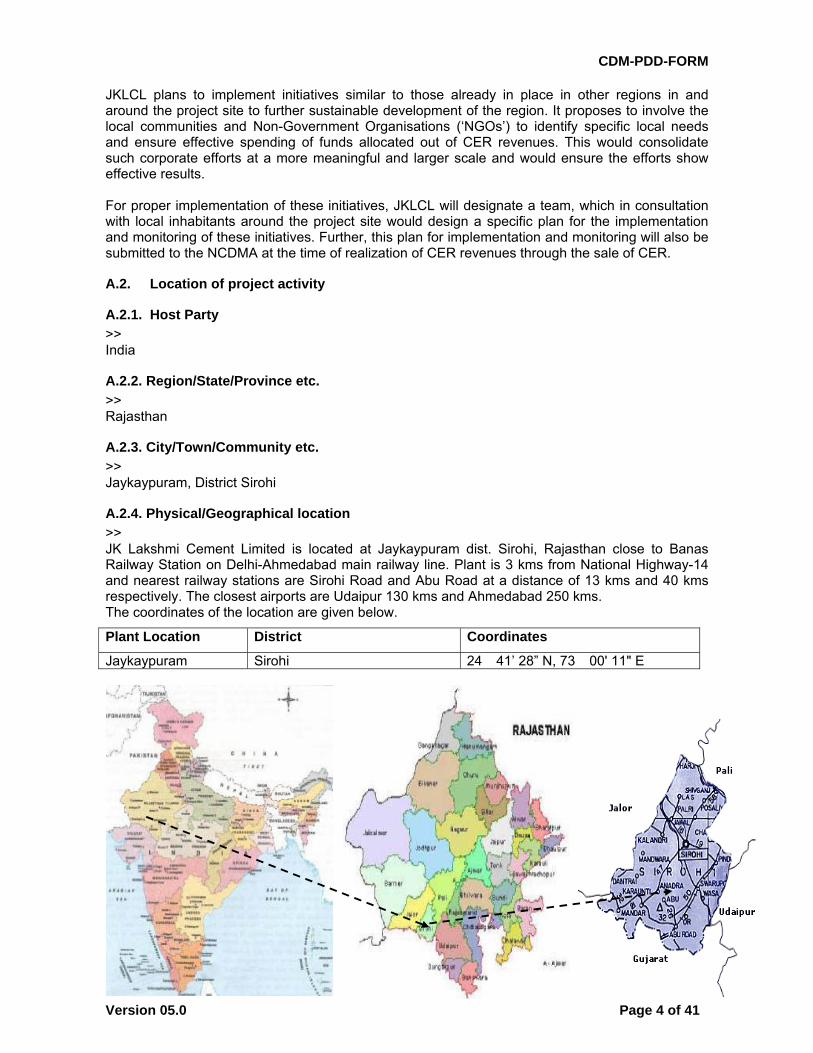
>> JK Lakshmi Cement Limited is located at Jaykaypuram dist. Sirohi, Rajasthan close to Banas Railway Station on Delhi-Ahmedabad main railway line. Plant is 3 kms from National Highway-14 and nearest railway stations are Sirohi Road and Abu Road at a distance of 13 kms and 40 kms respectively. The closest airports are Udaipur 130 kms and Ahmedabad 250 kms. The coordinates of the location are given below.
Plant Location District Coordinates
Jaykaypuram Sirohi 24� 41’ 28” N, 73� 00' 11" E
CDM-PDD-FORM
Version 05.0 Page 5 of 41
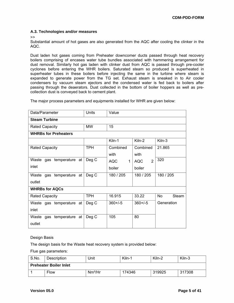
A.3. Technologies and/or measures
>> Substantial amount of hot gases are also generated from the AQC after cooling the clinker in the AQC. Dust laden hot gases coming from Preheater downcomer ducts passed through heat recovery boilers comprising of encases water tube bundles associated with hammering arrangement for dust removal. Similarly hot gas laden with clinker dust from AQC is passed through pre-cooler cyclones before entering the WHR boilers. Saturated steam so produced is superheated in superheater tubes in these boilers before injecting the same in the turbine where steam is expanded to generate power from the TG set. Exhaust steam is sneaked in to Air cooler condensers by vacuum steam ejectors and the condensed water is fed back to boilers after passing through the deaerators. Dust collected in the bottom of boiler hoppers as well as pre-collection dust is conveyed back to cement plant. The major process parameters and equipments installed for WHR are given below:
Data/Parameter Units Value
Steam Turbine
Rated Capacity MW 15
WHRBs for Preheaters
Kiln-1 Kiln-2 Kiln-3
Rated Capacity TPH Combined
with
AQC 1
boiler
Combined
with
AQC 2
boiler
21.865
Waste gas temperature at
inlet
Deg C 320
Waste gas temperature at
outlet
Deg C 180 / 205 180 / 205 180 / 205
WHRBs for AQCs
Rated Capacity TPH 16.915 33.22 No Steam
Generation Waste gas temperature at
inlet
Deg C 360+/-5 360+/-5
Waste gas temperature at
outlet
Deg C 105 80
Design Basis
The design basis for the Waste heat recovery system is provided below:
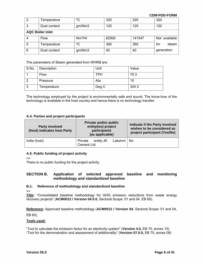
Flue gas parameters:
S.No. Description Unit Kiln-1 Kiln-2 Kiln-3
Preheater Boiler Inlet
1 Flow Nm³/Hr 174346 319925 317308
CDM-PDD-FORM
Version 05.0 Page 6 of 41
2 Temperature ºC 320 320 320
3 Dust content gm/Nm3 120 120 120
AQC Boiler Inlet
4 Flow Nm³/Hr 62500 141547 Not available
for steam
generation
5 Temperature ºC 360 360
6 Dust content gm/Nm3 40 40
The parameters of Steam generated from WHRB are:
S.No. Description Unit Value
1 Flow TPH 70.3
2 Pressure Ata 15
3 Temperature Deg C 324.3
The technology employed by the project is environmentally safe and sound. The know-how of the technology is available in the host country and hence there is no technology transfer.
A.4. Parties and project participants
Party involved (host) indicates host Party
Private and/or public entity(ies) project
participants (as applicable)
Indicate if the Party involved wishes to be considered as project participant (Yes/No)
India (host) Private entity-JK Lakshmi Cement Ltd.
No
A.5. Public funding of project activity
>> There is no public funding for the project activity.
SECTION B. Application of selected approved baseline and monitoring methodology and standardized baseline
B.1. Reference of methodology and standardized baseline
>> Title: “Consolidated baseline methodology for GHG emission reductions from waste energy recovery projects” (ACM0012 / Version 04.0.0, Sectoral Scope: 01 and 04, EB 60).
Reference: Approved baseline methodology (ACM0012 / Version 04, Sectoral Scope: 01 and 04,
EB 60).
Tools used: “Tool to calculate the emission factor for an electricity system” (Version 4.0, EB 75, annex 15) “Tool for the demonstration and assessment of additionality” (Version 07.0.0, EB 70, annex 08)
CDM-PDD-FORM
Version 05.0 Page 7 of 41
B.2. Applicability of methodology and standardized baseline
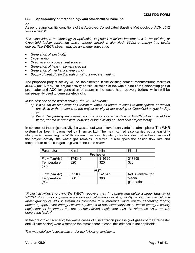
>> As per the applicability conditions of the Approved Consolidated Baseline Methodology- ACM 0012 version 04.0.0: The consolidated methodology is applicable to project activities implemented in an existing or Greenfield facility converting waste energy carried in identified WECM stream(s) into useful energy. The WECM stream may be an energy source for: Generation of electricity; Cogeneration; Direct use as process heat source; Generation of heat in element process; Generation of mechanical energy; or Supply of heat of reaction with or without process heating. The proposed project activity will be implemented in the existing cement manufacturing facility of JKLCL, unit-Sirohi. The project activity entails utilisation of the waste heat of the emanating gas of pre heater and AQC for generation of steam in the waste heat recovery boilers, which will be subsequently used to generate electricity. In the absence of the project activity, the WECM stream:
a) Would not be recovered and therefore would be flared, released to atmosphere, or remain unutilized in the absence of the project activity at the existing or Greenfield project facility; or
b) Would be partially recovered, and the unrecovered portion of WECM stream would be flared, vented or remained unutilised at the existing or Greenfield project facility.
In absence of the project activity the waste heat would have been vented to atmosphere. The WHR system has been implemented by Thermax Ltd. Thermax ltd. had also carried out a feasibility study for implementing the WHR system. The feasibility study clearly states that in the absence of the project activity, the waste gas remains unutilized. It also gives the design flow rate and temperature of the flue gas as given in the table below:
Parameter Kiln I Kiln II Kiln III Pre heater
Flow (Nm3/hr) 174346 319925 317308 Temperature (°C)
320 320 320
AQCFlow (Nm3/hr) 62500 141547 Not available for
steam generation
Temperature (°C)
360 360
“Project activities improving the WECM recovery may (i) capture and utilize a larger quantity of WECM stream as compared to the historical situation in existing facility, or capture and utilize a larger quantity of WECM stream as compared to a reference waste energy generating facility; and/or (ii) apply more energy efficient equipment to replace/modify/expand waste energy recovery equipment, or implement a more energy efficient equipment than the reference waste energy generating facility” In the pre-project scenario; the waste gases of clinkerization process (exit gases of the Pre-heater and Clinker cooler) were wasted to the atmosphere. Hence, this criterion is not applicable. The methodology is applicable under the following conditions:
CDM-PDD-FORM
Version 05.0 Page 8 of 41
For project activities which recover waste pressure, the methodology is applicable where waste pressure is used to generate electricity only and the electricity generated from waste pressure is measurable;
Regulations do not require the project facility to recover and/or utilize the waste energy prior to the implementation of the project activity;
The methodology is applicable to both Greenfield and existing waste energy generation facilities. If the production capacity of the project facility is expanded as a result of the project activity, the added production capacity must be treated as a Greenfield facility;
Waste energy that is released under abnormal operation (for example, emergencies, shut down) of the project facility shall not be included in the emission reduction calculations.
The project activity does not involve recovery of waste pressure. There is no regulation that requires the project facility to utilize the waste energy. The project activity is implemented in an existing facility. No capacity enhancement has taken place in the project facility as a result of the project activity. Waste energy that is released under abnormal operation of the project facility is not included in the emission reduction calculations. If multiple waste gas streams are available in the project facility and can be used interchangeably for various applications as part of the energy sources in the facility, the recovery of any waste gas stream, which would be totally or partially recovered in the absence of the project activity, shall not be reduced due to the implementation of CDM project activity. For such situations, the guidance provided in Annex 3 shall be followed. No waste gas stream that is being utilized in the project activity is being utilized prior to the implementation of the project activity in the project facility The methodology is not applicable to the cases where a WECM stream is partially recovered in the absence of the CDM project activity to supply the heat of reaction, and the recovery of this WECM stream is increased under the project activity to replace fossil fuels used for the purpose of supplying heat of reaction. The waste gas is being utilized in the project activity only for the purpose of electricity generation, the WECM was, in the pre-project scenario being vented to the atmosphere. This methodology is also not applicable to project activities where the waste gas/heat recovery project is implemented in a single-cycle power plant (e.g. gas turbine or diesel generator) to generate power. However, the projects recovering waste energy from single cycle and/or combined cycle power plants for the purpose of generation of heat only can apply this methodology. The project activity does not involve waste gas/heat recovery in a single cycle power plant. The emission reduction credits can be claimed up to the end of the lifetime of the waste energy generation equipment. The remaining lifetime of the equipment should be determined using the latest version of the Tool to determine the remaining lifetime of equipment. The emission reduction credits will be claimed only till the end of the lifetime of the waste energy generation equipment. The extent of use of waste energy from the waste energy generation facilities in the absence of the CDM project activity will be determined in accordance with the procedures provided in Annex 1 (for Greenfield project facilities) and in Annex 2 (for existing project facilities) to this methodology.
CDM-PDD-FORM
Version 05.0 Page 9 of 41
The extent of waste energy generation in the facility will be determined in accordance with annex 2 of the methodology ACM0012. The project activity satisfies all applicability criteria of the methodology ACM0012. Version 04
B.3. Project boundary
As per the applied methodology, ACM 0012 version 4, the project boundary is defined as: The geographical extent project boundary shall include the relevant WECM stream(s), equipment and energy distribution system in the following facilities:
1. The project facility; 2. The recipient facility (ies), which may be the same as the project facility.
The spatial extent of the grid is as defined in the “Tool to calculate the emission factor for an electricity System” The relevant equipment and energy distribution system cover: • In a project facility, the WECM stream(s), waste energy recovery and useful energy generation equipment, and distribution system(s) for useful project energy; • In a recipient facility, the equipment which receive useful energy supplied by the project, and
CDM-PDD-FORM
Version 05.0 Page 10 of 41
distribution system(s) for useful project energy.
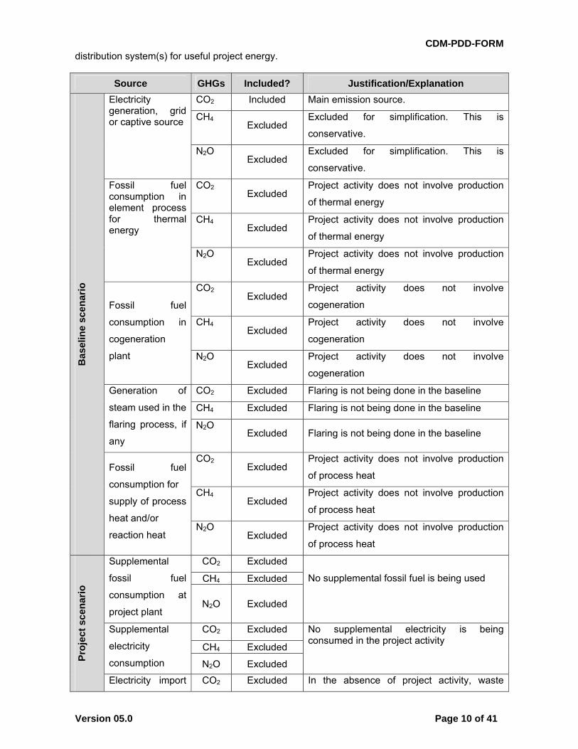
Source GHGs Included? Justification/Explanation B
asel
ine
scen
ario
Electricity generation, grid or captive source
CO2 Included Main emission source.
CH4 Excluded
Excluded for simplification. This is
conservative.
N2O Excluded
Excluded for simplification. This is
conservative.
Fossil fuel consumption in element process for thermal energy
CO2 Excluded
Project activity does not involve production
of thermal energy
CH4 Excluded
Project activity does not involve production
of thermal energy
N2O Excluded
Project activity does not involve production
of thermal energy
Fossil fuel
consumption in
cogeneration
plant
CO2 Excluded
Project activity does not involve
cogeneration
CH4 Excluded
Project activity does not involve
cogeneration
N2O Excluded
Project activity does not involve
cogeneration
Generation of
steam used in the
flaring process, if
any
CO2 Excluded Flaring is not being done in the baseline
CH4 Excluded Flaring is not being done in the baseline
N2O Excluded Flaring is not being done in the baseline
Fossil fuel
consumption for
supply of process
heat and/or
reaction heat
CO2 Excluded
Project activity does not involve production
of process heat
CH4 Excluded
Project activity does not involve production
of process heat
N2O Excluded
Project activity does not involve production
of process heat
Pro
ject
sce
nar
io
Supplemental
fossil fuel
consumption at
project plant
CO2 Excluded
No supplemental fossil fuel is being used
CH4 Excluded
N2O Excluded
Supplemental
electricity
consumption
CO2 Excluded No supplemental electricity is being consumed in the project activity
CH4 Excluded
N2O Excluded
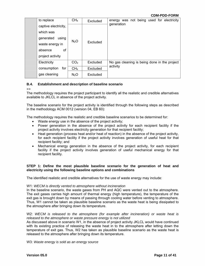
Electricity import CO2 Excluded In the absence of project activity, waste
CDM-PDD-FORM
Version 05.0 Page 11 of 41
to replace
captive electricity,
which was
generated using
waste energy in
absence of
project activity
CH4 Excluded energy was not being used for electricity generation
N2O Excluded
Electricity
consumption for
gas cleaning
CO2 Excluded No gas cleaning is being done in the project activity
CH4 Excluded
N2O Excluded
B.4. Establishment and description of baseline scenario
>> The methodology requires the project participant to identify all the realistic and credible alternatives available to JKLCL in absence of the project activity. The baseline scenario for the project activity is identified through the following steps as described in the methodology ACM 0012 (version 04, EB 60): The methodology requires the realistic and credible baseline scenarios to be determined for:
Waste energy use in the absence of the project activity; Power generation in the absence of the project activity for each recipient facility if the
project activity involves electricity generation for that recipient facility; Heat generation (process heat and/or heat of reaction) in the absence of the project activity,
for each recipient facility if the project activity involves generation of useful heat for that recipient facility; and
Mechanical energy generation in the absence of the project activity, for each recipient facility if the project activity involves generation of useful mechanical energy for that recipient facility.
STEP 1: Define the most plausible baseline scenario for the generation of heat and electricity using the following baseline options and combinations The identified realistic and credible alternatives for the use of waste energy may include: W1: WECM is directly vented to atmosphere without incineration In the baseline scenario, the waste gases from PH and AQC were vented out to the atmosphere. The exit gases carries high amount of thermal energy (high temperature), the temperature of the exit gas is brought down by means of passing through cooling water before venting to atmosphere. Thus, W1 cannot be taken as plausible baseline scenario as the waste heat is being dissipated to the atmosphere after bringing down its temperature. W2: WECM is released to the atmosphere (for example after incineration) or waste heat is released to the atmosphere or waste pressure energy is not utilized As discussed above in scenario W1, in the absence of project activity JKLCL would have continued with its existing practice of releasing the waste heat in to the atmosphere after letting down the temperature of exit gas. Thus, W2 has taken as plausible baseline scenario as the waste heat is released to the atmosphere after bringing down its temperature. W3: Waste energy is sold as an energy source
CDM-PDD-FORM
Version 05.0 Page 12 of 41
The project activity is based on waste heat recovery technology for power generation. No technology is available to capture the waste energy directly to export from the plant. Also project activity site is located at remote location; hence there are no users of heat located near to the cement production facilities of JKLCL. Hence this option is ruled out for baseline consideration. W4: Waste energy is used for meeting energy demand at the recipient facility(ies) This is a plausible baseline scenario. However, this option is not financially feasible without CDM revenue, as is elaborated in section B.5 of this PDD. W5: A portion of the quantity or energy of WECM is recovered for generation of heat and/or electricityand/or mechanical energy, while the rest of the waste energy produced at the project facility isflared/released to atmosphere/ unutilized As in the case of alternative W4, this alternative also involves investment in waste heat recovery equipment but with lesser energy output. Partial utilization of waste heat would result in further reducing financial returns from the investment in the waste heat recovery equipment. Hence, this is not a credible baseline scenario. W6: All the waste gas produced at the industrial facility is captured and used for export electricity generation or steam In the pre-project scenario, the JKLCL Sirohi plant is power deficit. In the post project scenario, there is going to be a capacity expansion at JKLCL, and hence the power demand is going to rise. In view of this, the use of waste heat for export electricity generation purposes is not a plausible scenario, since the JKLCL will first meet its own power requirement and only then will look to export power. For power generation, the realistic and credible alternative(s) may include P1: Proposed project activity not undertaken as a CDM project activity This is a plausible baseline scenario. However, this is not an economically unattractive option compared with other alternatives (fossil fuel based power generation). P2: On-site or off-site existing fossil fuel fired cogeneration plant The project activity does not involve co-generation, hence this is not a plausible baseline scenario. P3: On-site or off-site Greenfield fossil fuel fired cogeneration plant The project activity does not involve co-generation, hence this is not a plausible baseline scenario. P4: On-site or off-site existing renewable energy based cogeneration plant The project activity does not involve co-generation, hence this is not a plausible baseline scenario. P5: On-site or off-site Greenfield renewable energy based cogeneration plant The project activity does not involve co-generation, hence this is not a plausible baseline scenario. P6: On-site or off-site existing fossil fuel based existing identified captive power plant Before implementation of project activity, there is an existing 36 MW captive power plant. JKLCL is looking to expand its cement manufacturing facility; the waste heat recovery system would be installed to meet the increased power requirement on account of increased cement capacity. Therefore, it cannot be a credible baseline scenario. P7: On-site or off-site existing identified renewable energy or other waste energy based captive power Plant There is no existing renewable energy or other waste energy based captive power plant available to JKLCL. P8: On-site or off-site Greenfield fossil fuel based captive plant This is a credible baseline scenario.
CDM-PDD-FORM
Version 05.0 Page 13 of 41
P9: On-site or off-site Greenfield renewable energy or other waste energy based captive plant There is no potential for wind, hydro or solar etc. power available near the location of JKLCL, hence this is not a credible baseline scenario. P10: Sourced Grid-connected power plants The PP faces a prohibitive barrier for relying on grid electricity. Cement production is an energy intensive process and continuous supply of electricity is critical for the successful operation of the cement plant. The project promoter has faced numerous incidences, prior to the implementation of the project activity, of grid failure / voltage fluctuations which have resulted in shut down of major equipment, and production losses for the company. Despite several requests to the electricity distribution company to resolve the situation, the grid supply has remained erratic and unreliable.1 The management has therefore, drastically reduced its reliance on grid electricity over the years and progressively increased captive power generation capacity in order to eliminate dependence on the grid.2 Further, the unit cost of power generation from a new thermal power plant is less than that of importing electricity from the grid. The levelized unit cost for power generation by the fossil fuel based power plant is Rs. 3.52/unit whereas the unit cost of power purchase from grid is Rs. 4.67/unit. Hence, this baseline alternative is eliminated. P11: Existing captive electricity generation using waste energy (if project activity is captive generation using waste energy, this scenario represents captive generation with lower efficiency or lower recovery than project activity). There is no provision for capturing waste heat at the JKLCL plant before implementation of the project activity; hence this is not a credible baseline scenario. P12: Existing cogeneration using waste energy, but at a lower efficiency or lower recovery This is not applicable, since the project activity only involves power generation using waste heat recovery. For heat generation and mechanical energy, as there is no heat supply in the project activity, therefore the alternatives from H1 to H14 and M1 to M8 listed in the methodology are not credible and realistic and shall be excluded. Among all credible alternatives, the one that does not face any prohibitive barrier is to be considered as the baseline scenario. From the identified alternatives it can be found that alternative baseline scenario most suitable is: Project Scenario: Generation of Electricity Only Baseline options Waste energy Power energy
W2, W4, W5 P1,P8
STEP 2: Step 2 and/or Step 3 of the latest approved version of the Tool for the demonstration and assessment of additionality shall be used to identify the most plausible baseline scenarios by eliminating non-feasible options (e.g. alternatives where barriers are prohibitive or which are clearly economically unattractive). W4 represents the situation where the waste heat is used to meet the energy demand of the project facility. As explained in section B.5, this is not an economically attractive option. Hence this option is eliminated
1 Reference: Communications with Rajasthan Rajya Vidyut Prasaran Nigam Ltd.
2 Reference: Power generation data published in Annual Reports of the company
CDM-PDD-FORM
Version 05.0 Page 14 of 41
W5 represents the situation where a portion of the waste heat is utilized for energy generation. Since waste energy utilization as described in section B.5 is not an economically option, utilizing the waste heat partially is also economically unattractive, hence this is not a plausible baseline scenario. P1 is the scenario where the project activity is taken as a non CDM project. As explained in section B.5, this is not a financially attractive option, hence this is not a credible baseline scenario. Therefore, the scenarios for waste heat and power in the baseline are: Waste Heat: W2 Power: P8 Step 3: If more than one credible and plausible alternative scenario remain, the alternative Only one baseline alternative is left, therefore this step is not required. Key information and data used to determine baseline alternative scenario Key Information: Source: Evidence of grid failure: The project promoter has faced numerous incidences, prior to the implementation of the project activity, of grid failure / voltage fluctuations which have resulted in shut down of major equipment, and production losses for the company.
Communications with Rajasthan Rajya Vidyut Prasaran Nigam Ltd.
The levelized unit cost for power generation by the fossil fuel based power plant is Rs. 3.52/unit whereas the unit cost of power purchase from grid is Rs. 4.67/unit.
Levelized unit cost is based on assumptions used for calculation of IRR as presented in section B.5.
Cement production is an energy intensive process and continuous supply of electricity is critical for the successful operation of the cement plant. Power supply from grid is erratic / inadequate and cement plants in India rely on captive power generation for meeting power requirements.
Ninety fifth report on Performance of Cement Industry, Parliament of India, Rajya Sabha, Department Related Parliamentary Standing Committee on Commerce
The implementation of project activity is a voluntary initiative and is not a mandatory or legal requirement. The Electricity Act 20033 does not restrict or empower any authority to restrict the fuel choice for power generation. Further, the applicable environmental regulations do not restrict the use of wind energy and there is no legal requirement on the choice of a particular technology.
B.5. Demonstration of additionality
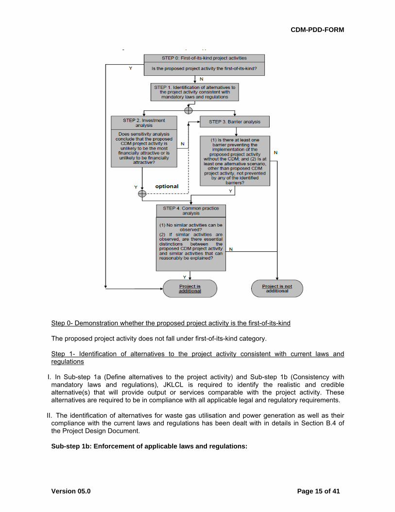
>> As per the decision 17/cp.7 para 43, a CDM project activity is additional if anthropogenic emissions of greenhouse gases by sources are reduced below those that would have occurred in absence of the registered CDM project activity. The methodology requires the project participant to determine its additionality based on the “Tool for the demonstration and assessment of additionality (version 07.0.0)”, agreed by the CDM Executive Board. The flowchart presented in below provides a step-by-step approach to establishing additionality of the project activity:
3 http://www.cercind.gov.in/08022007/Act-with-amendment.pdf
CDM-PDD-FORM
Version 05.0 Page 15 of 41
Step 0- Demonstration whether the proposed project activity is the first-of-its-kind The proposed project activity does not fall under first-of-its-kind category. Step 1- Identification of alternatives to the project activity consistent with current laws and regulations
I. In Sub-step 1a (Define alternatives to the project activity) and Sub-step 1b (Consistency with mandatory laws and regulations), JKLCL is required to identify the realistic and credible alternative(s) that will provide output or services comparable with the project activity. These alternatives are required to be in compliance with all applicable legal and regulatory requirements.
II. The identification of alternatives for waste gas utilisation and power generation as well as their compliance with the current laws and regulations has been dealt with in details in Section B.4 of the Project Design Document.
Sub-step 1b: Enforcement of applicable laws and regulations:
CDM-PDD-FORM
Version 05.0 Page 16 of 41
The Indian power sector was primarily dominated by the public sector and was regulated by the Electricity (Supply) Act, 1948 until the amendment of the act in 1991 to create the provision for private generating companies to setup projects. These were both replaced by the Electricity Act 2003 which is the applicable regulation for the project activity. As per Annex 3 of EB 22 it is stated that National and/or sectoral policies or regulations that give comparative advantages to less emission-intensive technologies need not be considered if implemented after 11th November 2001. However, even considering this act both the above alternatives are in compliance with all applicable legal and regulatory requirements as follows: The implementation of project activity is a voluntary initiative and is not a mandatory or legal requirement. The Electricity Act 20034 does not restrict or empower any authority to restrict the fuel choice for power generation. Further, the applicable environmental regulations do not restrict the use of wind energy and there is no legal requirement on the choice of a particular technology. Thus, considering that all the alternatives are in line with the applicable legal and regulatory requirements, the “no project option” i.e. continuation of current practice where in the equivalent amount of energy would have been produced by the project grid electricity system through its currently running power plants and by new capacity additions is the selected baseline scenario has been selected as baseline (as per ACM012).
III. Step 2. Investment analysis As per the investment analysis, the project participant is required to determine whether the project activity is economically or financially less attractive than other alternatives without the revenue from the sale of Certified Emission Reductions (CERs). To conduct the investment analysis, JKLCL is required to use the following sub-steps: Sub-step 2a. Determine appropriate analysis method The project activity will generate electricity for in-house consumption and has financial implications other than those related to CDM. Therefore ‘Option-I: Simple cost analysis’ would not be an appropriate analysis method. Amongst the other two options i.e. ‘Option-II: Investment comparison analysis’ and ‘Option-III: Benchmark analysis’, JKLCL has adopted the investment comparison analysis wherein the financial indicator(s) of the project activity (i.e. scenario 1) is compared with other alternative (i.e. “scenario-2”). If at least one of the alternatives has a better indicator (e.g. higher project IRR), then the project activity cannot be considered as the most financially attractive option. Sub-step 2b. Option II. Apply investment comparison analysis JKLCL has conducted an investment comparison analysis for all the alternatives (i.e. scenario- 1, scenario-2) that were available with them in absence of the project activity. The project IRR has been considered as the financial indicator for the investment comparison analysis. The project IRR is commonly used by financing institutions and project developers for making investment decisions, and is considered an appropriate financial indicator in the context of the project activity. All relevant assumptions used for the investment comparison analysis have been provided below Sub-step 2c. Calculation and comparison of financial indicators
Scenario 2 (i.e. baseline)
Project case without CDM (scenario-1)
4 http://www.cercind.gov.in/08022007/Act-with-amendment.pdf
CDM-PDD-FORM
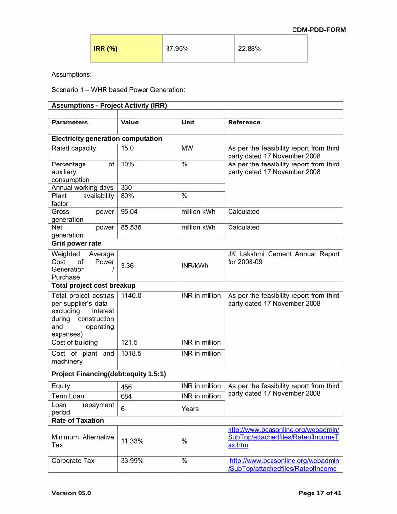
Version 05.0 Page 17 of 41
IRR (%) 37.95% 22.88%
Assumptions: Scenario 1 – WHR based Power Generation: Assumptions - Project Activity (IRR) Parameters Value Unit Reference Electricity generation computation
Rated capacity 15.0 MW As per the feasibility report from third party dated 17 November 2008
Percentage of auxiliary consumption
10% % As per the feasibility report from third party dated 17 November 2008
Annual working days 330 Plant availability factor
80% %
Gross power generation
95.04 million kWh Calculated
Net power generation
85.536 million kWh Calculated
Grid power rate
Weighted Average Cost of Power Generation / Purchase
3.36 INR/kWh
JK Lakshmi Cement Annual Report for 2008-09
Total project cost breakup
Total project cost(as per supplier's data – excluding interest during construction and operating expenses)
1140.0 INR in million As per the feasibility report from third party dated 17 November 2008
Cost of building 121.5 INR in million
Cost of plant and machinery
1018.5 INR in million
Project Financing(debt:equity 1.5:1)
Equity 456 INR in million As per the feasibility report from third party dated 17 November 2008 Term Loan 684 INR in million
Loan repayment period
6 Years
Rate of Taxation
Minimum Alternative Tax
11.33% %
http://www.bcasonline.org/webadmin/SubTop/attachedfiles/RateofIncomeTax.htm
Corporate Tax
33.99% % http://www.bcasonline.org/webadmin/SubTop/attachedfiles/RateofIncome
CDM-PDD-FORM
Version 05.0 Page 18 of 41
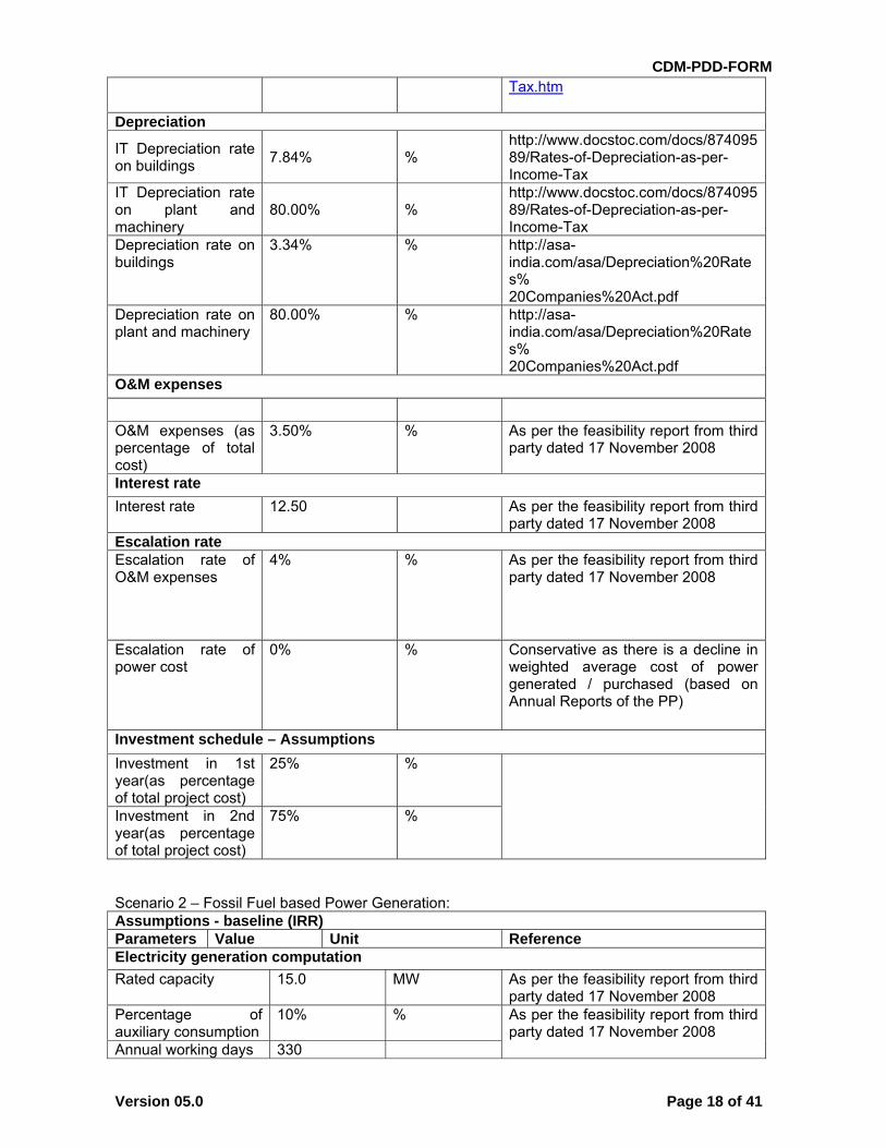
Tax.htm
Depreciation
IT Depreciation rate on buildings
7.84% % http://www.docstoc.com/docs/87409589/Rates-of-Depreciation-as-per-Income-Tax
IT Depreciation rate on plant and machinery
80.00% % http://www.docstoc.com/docs/87409589/Rates-of-Depreciation-as-per-Income-Tax
Depreciation rate on buildings
3.34% % http://asa-india.com/asa/Depreciation%20Rates% 20Companies%20Act.pdf
Depreciation rate on plant and machinery
80.00% % http://asa-india.com/asa/Depreciation%20Rates% 20Companies%20Act.pdf
O&M expenses
O&M expenses (as percentage of total cost)
3.50% % As per the feasibility report from third party dated 17 November 2008
Interest rate
Interest rate 12.50 As per the feasibility report from third party dated 17 November 2008
Escalation rate Escalation rate of O&M expenses
4% % As per the feasibility report from third party dated 17 November 2008
Escalation rate of power cost
0% % Conservative as there is a decline in weighted average cost of power generated / purchased (based on Annual Reports of the PP)
Investment schedule – Assumptions
Investment in 1st year(as percentage of total project cost)
25% %
Investment in 2nd year(as percentage of total project cost)
75% %
Scenario 2 – Fossil Fuel based Power Generation: Assumptions - baseline (IRR) Parameters Value Unit Reference Electricity generation computation
Rated capacity 15.0 MW As per the feasibility report from third party dated 17 November 2008
Percentage of auxiliary consumption
10% % As per the feasibility report from third party dated 17 November 2008
Annual working days 330
CDM-PDD-FORM
Version 05.0 Page 19 of 41
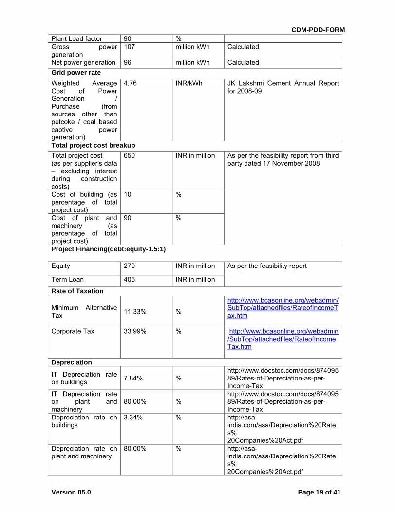
Plant Load factor 90 % Gross power generation
107 million kWh Calculated
Net power generation 96 million kWh Calculated
Grid power rate
Weighted Average Cost of Power Generation / Purchase (from sources other than petcoke / coal based captive power generation)
4.76 INR/kWh JK Lakshmi Cement Annual Report for 2008-09
Total project cost breakup
Total project cost (as per supplier's data – excluding interest during construction costs)
650 INR in million As per the feasibility report from third party dated 17 November 2008
Cost of building (as percentage of total project cost)
10 %
Cost of plant and machinery (as percentage of total project cost)
90 %
Project Financing(debt:equity-1.5:1)
Equity 270 INR in million As per the feasibility report
Term Loan 405 INR in million
Rate of Taxation
Minimum Alternative Tax
11.33% %
http://www.bcasonline.org/webadmin/SubTop/attachedfiles/RateofIncomeTax.htm
Corporate Tax
33.99% % http://www.bcasonline.org/webadmin/SubTop/attachedfiles/RateofIncomeTax.htm
Depreciation
IT Depreciation rate on buildings
7.84% % http://www.docstoc.com/docs/87409589/Rates-of-Depreciation-as-per-Income-Tax
IT Depreciation rate on plant and machinery
80.00% % http://www.docstoc.com/docs/87409589/Rates-of-Depreciation-as-per-Income-Tax
Depreciation rate on buildings
3.34% % http://asa-india.com/asa/Depreciation%20Rates% 20Companies%20Act.pdf
Depreciation rate on plant and machinery
80.00% % http://asa-india.com/asa/Depreciation%20Rates% 20Companies%20Act.pdf
CDM-PDD-FORM
Version 05.0 Page 20 of 41
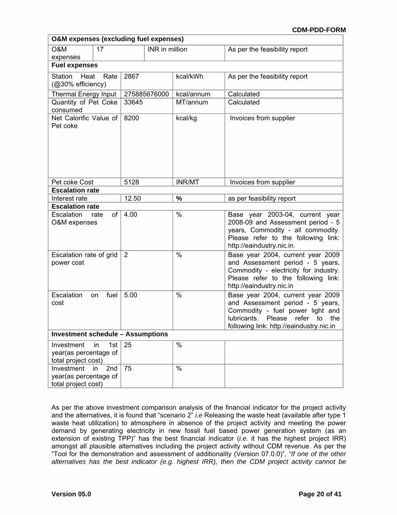
O&M expenses (excluding fuel expenses)
O&M expenses
17 INR in million As per the feasibility report
Fuel expenses
Station Heat Rate (@30% efficiency)
2867 kcal/kWh As per the feasibility report
Thermal Energy Input 275885676000 kcal/annum Calculated Quantity of Pet Coke consumed
33645 MT/annum Calculated
Net Calorific Value of Pet coke
8200 kcal/kg Invoices from supplier
Pet coke Cost 5128 INR/MT Invoices from supplier Escalation rate Interest rate 12.50 % as per feasibility report Escalation rate Escalation rate of O&M expenses
4.00 % Base year 2003-04, current year 2008-09 and Assessment period - 5 years, Commodity - all commodity. Please refer to the following link: http://eaindustry.nic.in.
Escalation rate of grid power cost
2 % Base year 2004, current year 2009 and Assessment period - 5 years, Commodity - electricity for industry. Please refer to the following link: http://eaindustry.nic.in
Escalation on fuel cost
5.00 % Base year 2004, current year 2009 and Assessment period - 5 years, Commodity - fuel power light and lubricants. Please refer to the following link: http://eaindustry.nic.in
Investment schedule – Assumptions
Investment in 1st year(as percentage of total project cost)
25 %
Investment in 2nd year(as percentage of total project cost)
75 %
As per the above investment comparison analysis of the financial indicator for the project activity and the alternatives, it is found that “scenario 2” i.e Releasing the waste heat (available after type 1 waste heat utilization) to atmosphere in absence of the project activity and meeting the power demand by generating electricity in new fossil fuel based power generation system (as an extension of existing TPP)” has the best financial indicator (i.e. it has the highest project IRR) amongst all plausible alternatives including the project activity without CDM revenue. As per the “Tool for the demonstration and assessment of additionality (Version 07.0.0)”, “If one of the other alternatives has the best indicator (e.g. highest IRR), then the CDM project activity cannot be
CDM-PDD-FORM
Version 05.0 Page 21 of 41
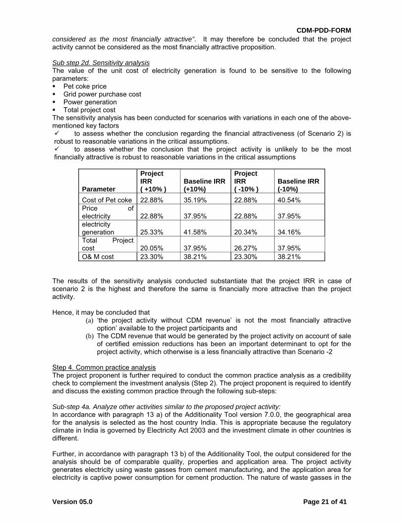
considered as the most financially attractive”. It may therefore be concluded that the project activity cannot be considered as the most financially attractive proposition. Sub step 2d. Sensitivity analysis The value of the unit cost of electricity generation is found to be sensitive to the following parameters: Pet coke price Grid power purchase cost Power generation Total project cost The sensitivity analysis has been conducted for scenarios with variations in each one of the above-mentioned key factors to assess whether the conclusion regarding the financial attractiveness (of Scenario 2) is robust to reasonable variations in the critical assumptions. to assess whether the conclusion that the project activity is unlikely to be the most financially attractive is robust to reasonable variations in the critical assumptions
Parameter
Project IRR ( +10% )
Baseline IRR (+10%)
Project IRR ( -10% )
Baseline IRR (-10%)
Cost of Pet coke 22.88% 35.19% 22.88% 40.54% Price of electricity 22.88% 37.95% 22.88% 37.95% electricity generation 25.33% 41.58% 20.34% 34.16% Total Project cost 20.05% 37.95% 26.27% 37.95% O& M cost 23.30% 38.21% 23.30% 38.21%
The results of the sensitivity analysis conducted substantiate that the project IRR in case of scenario 2 is the highest and therefore the same is financially more attractive than the project activity. Hence, it may be concluded that
(a) ‘the project activity without CDM revenue’ is not the most financially attractive option’ available to the project participants and
(b) The CDM revenue that would be generated by the project activity on account of sale of certified emission reductions has been an important determinant to opt for the project activity, which otherwise is a less financially attractive than Scenario -2
Step 4. Common practice analysis The project proponent is further required to conduct the common practice analysis as a credibility check to complement the investment analysis (Step 2). The project proponent is required to identify and discuss the existing common practice through the following sub-steps: Sub-step 4a. Analyze other activities similar to the proposed project activity: In accordance with paragraph 13 a) of the Additionality Tool version 7.0.0, the geographical area for the analysis is selected as the host country India. This is appropriate because the regulatory climate in India is governed by Electricity Act 2003 and the investment climate in other countries is different. Further, in accordance with paragraph 13 b) of the Additionality Tool, the output considered for the analysis should be of comparable quality, properties and application area. The project activity generates electricity using waste gasses from cement manufacturing, and the application area for electricity is captive power consumption for cement production. The nature of waste gasses in the
CDM-PDD-FORM
Version 05.0 Page 22 of 41
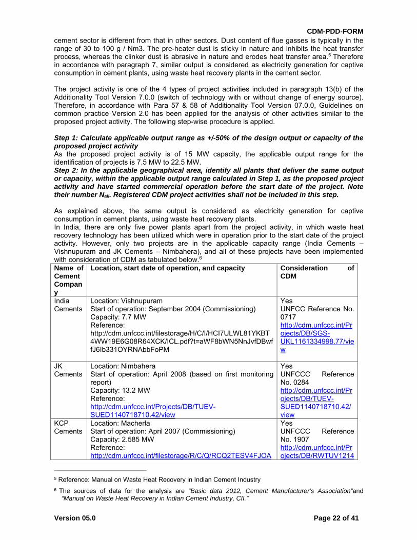
cement sector is different from that in other sectors. Dust content of flue gasses is typically in the range of 30 to 100 g / Nm3. The pre-heater dust is sticky in nature and inhibits the heat transfer process, whereas the clinker dust is abrasive in nature and erodes heat transfer area.5 Therefore in accordance with paragraph 7, similar output is considered as electricity generation for captive consumption in cement plants, using waste heat recovery plants in the cement sector. The project activity is one of the 4 types of project activities included in paragraph 13(b) of the Additionality Tool Version 7.0.0 (switch of technology with or without change of energy source). Therefore, in accordance with Para 57 & 58 of Additionality Tool Version 07.0.0, Guidelines on common practice Version 2.0 has been applied for the analysis of other activities similar to the proposed project activity. The following step-wise procedure is applied. Step 1: Calculate applicable output range as +/-50% of the design output or capacity of the proposed project activity As the proposed project activity is of 15 MW capacity, the applicable output range for the identification of projects is 7.5 MW to 22.5 MW. Step 2: In the applicable geographical area, identify all plants that deliver the same output or capacity, within the applicable output range calculated in Step 1, as the proposed project activity and have started commercial operation before the start date of the project. Note their number Nall. Registered CDM project activities shall not be included in this step. As explained above, the same output is considered as electricity generation for captive consumption in cement plants, using waste heat recovery plants. In India, there are only five power plants apart from the project activity, in which waste heat recovery technology has been utilized which were in operation prior to the start date of the project activity. However, only two projects are in the applicable capacity range (India Cements – Vishnupuram and JK Cements – Nimbahera), and all of these projects have been implemented with consideration of CDM as tabulated below.6 Name of Cement Company
Location, start date of operation, and capacity Consideration of CDM
India Cements
Location: Vishnupuram Start of operation: September 2004 (Commissioning) Capacity: 7.7 MW Reference: http://cdm.unfccc.int/filestorage/H/C/I/HCI7ULWL81YKBT4WW19E6G08R64XCK/ICL.pdf?t=aWF8bWN5NnJvfDBwffJ6Ib331OYRNAbbFoPM
Yes UNFCC Reference No. 0717 http://cdm.unfccc.int/Projects/DB/SGS-UKL1161334998.77/view
JK Cements
Location: Nimbahera Start of operation: April 2008 (based on first monitoring report) Capacity: 13.2 MW Reference: http://cdm.unfccc.int/Projects/DB/TUEV-SUED1140718710.42/view
Yes UNFCCC Reference No. 0284 http://cdm.unfccc.int/Projects/DB/TUEV-SUED1140718710.42/view
KCP Cements
Location: Macherla Start of operation: April 2007 (Commissioning) Capacity: 2.585 MW Reference: http://cdm.unfccc.int/filestorage/R/C/Q/RCQ2TESV4FJOA
Yes UNFCCC Reference No. 1907 http://cdm.unfccc.int/Projects/DB/RWTUV1214
5 Reference: Manual on Waste Heat Recovery in Indian Cement Industry
6 The sources of data for the analysis are “Basic data 2012, Cement Manufacturer’s Association”and “Manual on Waste Heat Recovery in Indian Cement Industry, CII.”
CDM-PDD-FORM
Version 05.0 Page 23 of 41
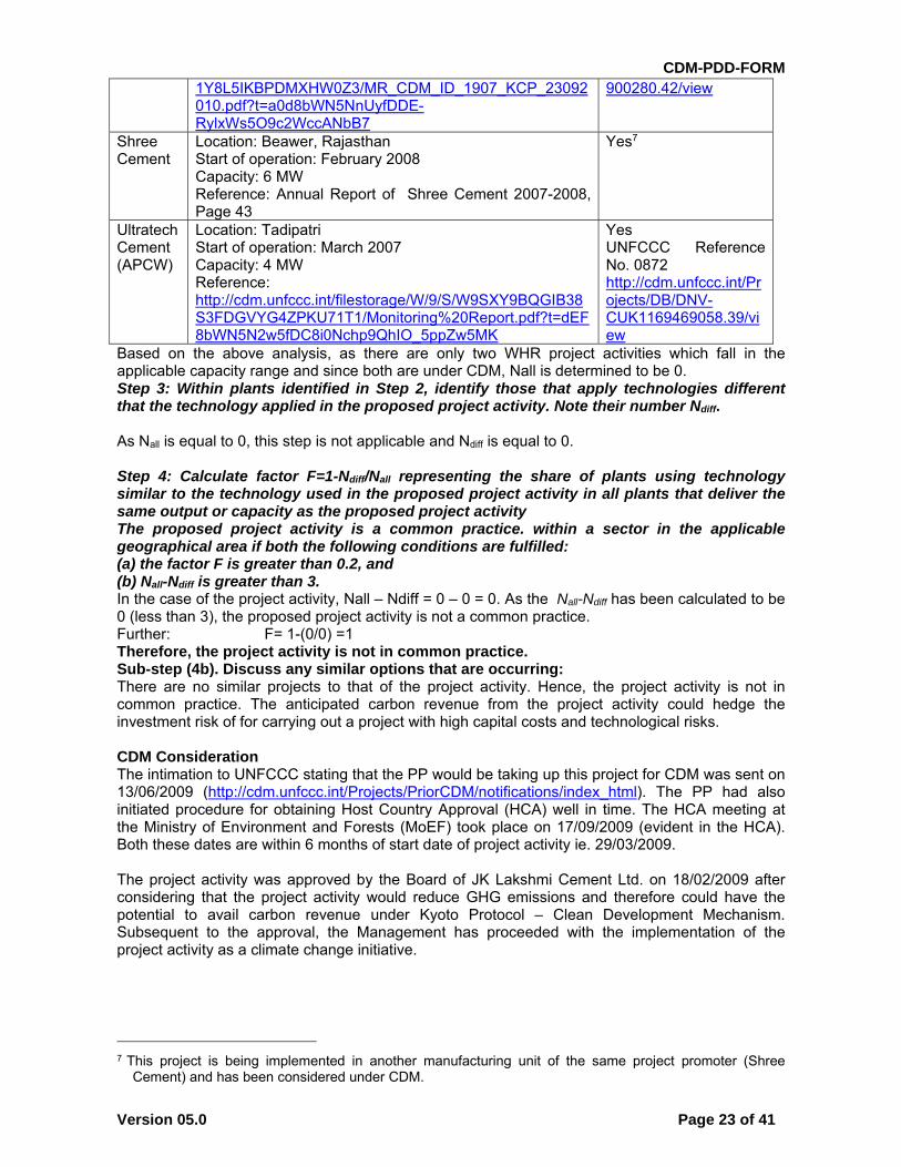
1Y8L5IKBPDMXHW0Z3/MR_CDM_ID_1907_KCP_23092010.pdf?t=a0d8bWN5NnUyfDDE-RylxWs5O9c2WccANbB7
900280.42/view
Shree Cement
Location: Beawer, Rajasthan Start of operation: February 2008 Capacity: 6 MW Reference: Annual Report of Shree Cement 2007-2008, Page 43
Yes7
Ultratech Cement (APCW)
Location: Tadipatri Start of operation: March 2007 Capacity: 4 MW Reference: http://cdm.unfccc.int/filestorage/W/9/S/W9SXY9BQGIB38S3FDGVYG4ZPKU71T1/Monitoring%20Report.pdf?t=dEF8bWN5N2w5fDC8i0Nchp9QhIO_5ppZw5MK
Yes UNFCCC Reference No. 0872 http://cdm.unfccc.int/Projects/DB/DNV-CUK1169469058.39/view
Based on the above analysis, as there are only two WHR project activities which fall in the applicable capacity range and since both are under CDM, Nall is determined to be 0. Step 3: Within plants identified in Step 2, identify those that apply technologies different that the technology applied in the proposed project activity. Note their number Ndiff. As Nall is equal to 0, this step is not applicable and Ndiff is equal to 0. Step 4: Calculate factor F=1-Ndiff/Nall representing the share of plants using technology similar to the technology used in the proposed project activity in all plants that deliver the same output or capacity as the proposed project activity The proposed project activity is a common practice. within a sector in the applicable geographical area if both the following conditions are fulfilled: (a) the factor F is greater than 0.2, and (b) Nall-Ndiff is greater than 3. In the case of the project activity, Nall – Ndiff = 0 – 0 = 0. As the Nall-Ndiff has been calculated to be 0 (less than 3), the proposed project activity is not a common practice. Further: F= 1-(0/0) =1 Therefore, the project activity is not in common practice. Sub-step (4b). Discuss any similar options that are occurring: There are no similar projects to that of the project activity. Hence, the project activity is not in common practice. The anticipated carbon revenue from the project activity could hedge the investment risk of for carrying out a project with high capital costs and technological risks. CDM Consideration The intimation to UNFCCC stating that the PP would be taking up this project for CDM was sent on 13/06/2009 (http://cdm.unfccc.int/Projects/PriorCDM/notifications/index_html). The PP had also initiated procedure for obtaining Host Country Approval (HCA) well in time. The HCA meeting at the Ministry of Environment and Forests (MoEF) took place on 17/09/2009 (evident in the HCA). Both these dates are within 6 months of start date of project activity ie. 29/03/2009. The project activity was approved by the Board of JK Lakshmi Cement Ltd. on 18/02/2009 after considering that the project activity would reduce GHG emissions and therefore could have the potential to avail carbon revenue under Kyoto Protocol – Clean Development Mechanism. Subsequent to the approval, the Management has proceeded with the implementation of the project activity as a climate change initiative.
7 This project is being implemented in another manufacturing unit of the same project promoter (Shree
Cement) and has been considered under CDM.
CDM-PDD-FORM
Version 05.0 Page 24 of 41
B.6. Emission reductions
B.6.1. Explanation of methodological choices
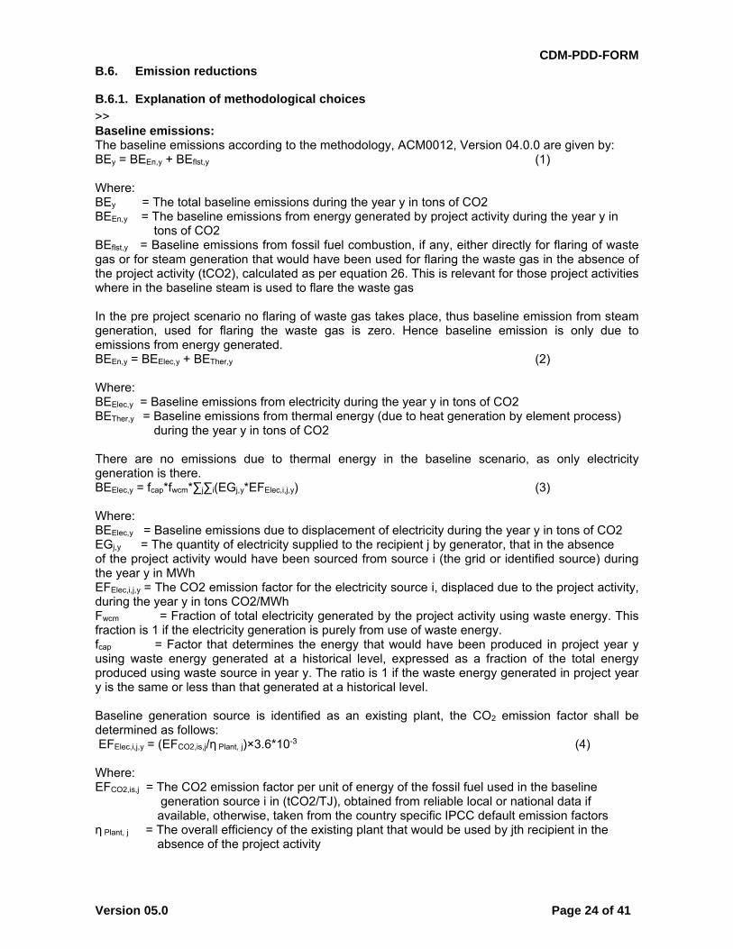
>> Baseline emissions: The baseline emissions according to the methodology, ACM0012, Version 04.0.0 are given by: BEy = BEEn,y + BEflst,y (1) Where: BEy = The total baseline emissions during the year y in tons of CO2 BEEn,y = The baseline emissions from energy generated by project activity during the year y in tons of CO2 BEflst,y = Baseline emissions from fossil fuel combustion, if any, either directly for flaring of waste gas or for steam generation that would have been used for flaring the waste gas in the absence of the project activity (tCO2), calculated as per equation 26. This is relevant for those project activities where in the baseline steam is used to flare the waste gas In the pre project scenario no flaring of waste gas takes place, thus baseline emission from steam generation, used for flaring the waste gas is zero. Hence baseline emission is only due to emissions from energy generated. BEEn,y = BEElec,y + BETher,y (2) Where: BEElec,y = Baseline emissions from electricity during the year y in tons of CO2 BETher,y = Baseline emissions from thermal energy (due to heat generation by element process) during the year y in tons of CO2 There are no emissions due to thermal energy in the baseline scenario, as only electricity generation is there. BEElec,y = fcap*fwcm*∑j∑i(EGj,y*EFElec,i,j,y) (3) Where: BEElec,y = Baseline emissions due to displacement of electricity during the year y in tons of CO2 EGj,y = The quantity of electricity supplied to the recipient j by generator, that in the absence of the project activity would have been sourced from source i (the grid or identified source) during the year y in MWh EFElec,i,j,y = The CO2 emission factor for the electricity source i, displaced due to the project activity, during the year y in tons CO2/MWh Fwcm = Fraction of total electricity generated by the project activity using waste energy. This fraction is 1 if the electricity generation is purely from use of waste energy. fcap = Factor that determines the energy that would have been produced in project year y using waste energy generated at a historical level, expressed as a fraction of the total energy produced using waste source in year y. The ratio is 1 if the waste energy generated in project year y is the same or less than that generated at a historical level. Baseline generation source is identified as an existing plant, the CO2 emission factor shall be determined as follows: EFElec,i,j,y = (EFCO2,is,j/η Plant, j)×3.6*10-3 (4) Where: EFCO2,is,j = The CO2 emission factor per unit of energy of the fossil fuel used in the baseline generation source i in (tCO2/TJ), obtained from reliable local or national data if available, otherwise, taken from the country specific IPCC default emission factors η Plant, j = The overall efficiency of the existing plant that would be used by jth recipient in the absence of the project activity
CDM-PDD-FORM
Version 05.0 Page 25 of 41
Calculation of the energy generated (electricity and/or steam) in units supplied by WECM and other fuels In the project activity, electricity is generated using only waste energy. Thus, fwcm value according to the guidance given above will remain fixed as 1. fwcm = 1 Capping of baseline emissions The cap can be estimated using the three Methods as specified in ACM0012. Method-1 is used to estimate the cap if historical data on the WECM flow rate is available. In case of project activities implemented in a new facility, or in facilities where three-year data on WECM is unavailable, Method-2 is used. In case of technical limitations in direct monitoring of waste heat / pressure of waste energy carrying medium (WECM), then Method-3 is used. As historical data on flue gas flowrate is not available, Method-1 can not be applied to the project activity. Further Method-2 can not be applied as it is not technically feasible to install a flow meter to monitor flue gases. The flue gasses at both the entry and exit point of the WHRB have high particulate content, due to which it is not technically feasible to install flow meters for monitoring the flow rate of flue gases.8 Therefore, in order to calculate fcap method 3 is applied. There are two cases in Method 3: Case 1: The energy is recovered from WECM and converted into final output energy through a waste heat recovery equipment. For example, the useful energy (e.g., steam) is produced using waste energy generated by a chemical reaction. For such cases fcap should be the ratio of maximum energy that could be recovered (MER) by the waste heat recovery equipment implemented under the CDM project activity and the actual energy recovered under the project activity (using direct measurement). The MER should be based on information on the characteristics of the key product/by product. For existing facilities this can be obtained from historical information and for Greenfield facilities, manufacturer’s specifications on these key parameters can be used. Case 2: The energy is recovered from WECM in intermediate energy recovery equipment using an intermediate source. For example, an intermediate source to carry energy from primary WECM may include the sources such as water, oil or air to extract waste energy entrapped in chemicals (heat of reaction) or solids (sensible heat), which is further recovered in the waste heat recovery equipment to generate final output energy. For such cases fcap should be the ratio of maximum energy that could be recovered (MER) by waste heat recovery equipment implemented under the CDM project activity (considering the losses due to exchange of energy) and actual intermediate energy recovered under the project activity (using direct measurement). The MER should be based on information on the characteristics of the key product/by product. For existing facilities this can be collected from historical information and for Greenfield facilities, manufacturers’ specifications on these key parameters. The final output energy which is the generated electricity of WHR system is measured. Therefore, Case 1 of Method 3 is applicable. The total heat that can be absorbed into boiler feed water is estimated in the baseline and the same is monitored in the project case. Under this method, following equations should be used to estimate fcap. fcap = QOE,BL/QOE,,y (5) Where:
8 Reference: Technical evaluation by Thermal Limited
CDM-PDD-FORM
Version 05.0 Page 26 of 41
QOE,BL = Output/intermediate energy that can be produced, to be determined on the basis of maximum energy that could be recovered from the WECM (MER), which would have been released (or WECM would have been flared or energy content of WECM would have been wasted) in the absence of CDM project activity (TJ) QOE,y = Quantity of actual output energy generated during year y (TJ) In case of the proposed project activity QOE,BL, consists of the theoretical maximum electrical output (in kWh) that can be generated with the available waste heat, while QOE,y is the actual electrical output of the project in year y (in kWh). The value of QOE, BL will be determined according to the specifications in FSR which is based on the information on the characteristics of the key product/by product.
Project emissions According to ACM 0012, Project Emissions include emissions due to (1) combustion of auxiliary fuel to supplement waste gas/heat and (2) electricity emissions due to consumption of electricity for cleaning of gas before being used for generation of energy or other supplementary electricity consumption. Since no auxiliary fuels will be fired in the proposed project activity, project activity emissions are not applicable. Also, there is no additional cleaning of gas for the project activity. Further, the electricity consumption of the project activity will be accounted for in EGj and hence no separate calculation of project emissions due to electricity consumption is required. Leakage No leakage is applicable under this methodology. Emission Reductions The emission reduction ERy by the project activity during a given year y is the difference between the baseline emissions through substitution of electricity generation by captive coal based thermal power plant (BEy) and project emissions (PEy), as follows: ERy = BEy – PEy
Where: ERy = are the emission reductions of the project activity during the year y in tonnes of CO2 BEy = are the baseline emissions due to the displacement of electricity during the year y in tonnes of CO2 PEy = are the project emissions during the year y in tonnes of CO2
Since the project emissions are non-existent in the project activity so the emission reductions (ERy) is equal to the baseline emissions due to the displacement of electricity (BEy) ERy = BEy
B.6.2. Data and parameters fixed ex ante
(Copy this table for each piece of data and parameter.)
Data / Parameter ηplant,j
Unit %
Description Baseline efficiency of captive power plant
Source of data ACM 0012 version 4
Value(s) applied 39
CDM-PDD-FORM
Version 05.0 Page 27 of 41
Choice of data or Measurement methods and procedures
As per the methodology ACM 0012 version 4, the “Tool to determine
the baseline efficiency of thermal or electric energy generation systems”
has been applied to determine the efficiency. Option (f) use of default
values has been adopted. Annex 1 of the “Tool to calculate emission
factor for an electricity system” is referred for default values of electricity
generation technologies. The default value is applied for new
“subcritical coal based power plants.”
Purpose of data To calculate baseline emissions
Additional comment --
Data / Parameter QOE,BL
Unit TJ
Description Output/intermediate energy that can be produced, to be determined on
the basis of maximum energy that could be recovered from the WECM
(MER), which would have been released (or WECM would have been
flared or energy content of WECM would have been wasted) in the
absence of CDM project activity
Source of data Plant records
Value(s) applied 1489
Choice of data or Measurement methods and procedures
This parameter is used for determination of fcap as per method 3 as
given in the methodology ACM 0012 version 4.
The value of output energy that can be recovered is based on the heat
and energy balance which gives the following parameters for steam
input to TG:
Steam flow rate: 70.3 TPH
Steam enthalpy: 738.8 kcal /kg
Feed water enthalpy: 100.06 kcal/kg
Further, it is assumed that steam would be generated continuously for
330 days and 24 hours per day. The calculation of output energy based
on the above-mentioned parameters is included in the ER sheet.
Purpose of data To calculate baseline emissions
Additional comment --
CDM-PDD-FORM
Version 05.0 Page 28 of 41
B.6.3. Ex ante calculation of emission reductions
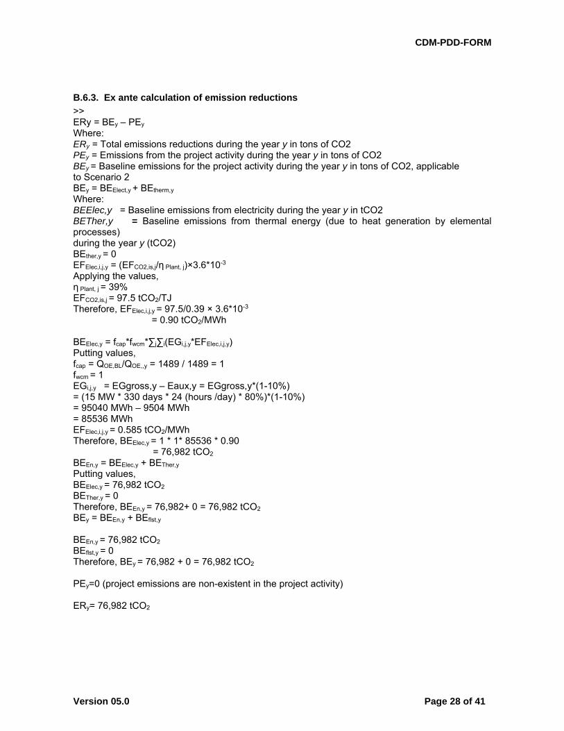
>> ERy = BEy – PEy Where: ERy = Total emissions reductions during the year y in tons of CO2 PEy = Emissions from the project activity during the year y in tons of CO2 BEy = Baseline emissions for the project activity during the year y in tons of CO2, applicable to Scenario 2 BEy = BEElect,y + BEtherm,y
Where: BEElec,y = Baseline emissions from electricity during the year y in tCO2 BETher,y = Baseline emissions from thermal energy (due to heat generation by elemental processes) during the year y (tCO2) BEther,y = 0 EFElec,i,j,y = (EFCO2,is,j/η Plant, j)×3.6*10-3 Applying the values, η Plant, j = 39% EFCO2,is,j = 97.5 tCO2/TJ Therefore, EFElec,i,j,y = 97.5/0.39 × 3.6*10-3
= 0.90 tCO2/MWh BEElec,y = fcap*fwcm*∑j∑i(EGi,j,y*EFElec,i,j,y) Putting values, fcap = QOE,BL/QOE,,y = 1489 / 1489 = 1 fwcm = 1 EGi,j,y = EGgross,y – Eaux,y = EGgross,y*(1-10%) = (15 MW * 330 days * 24 (hours /day) * 80%)*(1-10%) = 95040 MWh – 9504 MWh = 85536 MWh EFElec,i,j,y = 0.585 tCO2/MWh Therefore, BEElec,y = 1 * 1* 85536 * 0.90 = 76,982 tCO2 BEEn,y = BEElec,y + BETher,y Putting values, BEElec,y = 76,982 tCO2
BETher,y = 0 Therefore, BEEn,y = 76,982+ 0 = 76,982 tCO2 BEy = BEEn,y + BEflst,y BEEn,y = 76,982 tCO2
BEflst,y = 0 Therefore, BEy = 76,982 + 0 = 76,982 tCO2
PEy=0 (project emissions are non-existent in the project activity) ERy= 76,982 tCO2
CDM-PDD-FORM
Version 05.0 Page 29 of 41
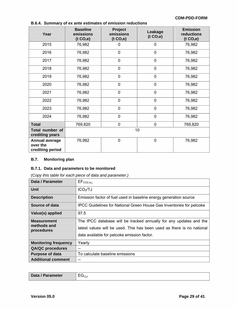
B.6.4. Summary of ex ante estimates of emission reductions
Year Baseline
emissions (t CO2e)
Project emissions
(t CO2e)
Leakage (t CO2e)
Emission reductions
(t CO2e)
2015 76,982 0 0 76,982
2016 76,982 0 0 76,982
2017 76,982 0 0 76,982
2018 76,982 0 0 76,982
2019 76,982 0 0 76,982
2020 76,982 0 0 76,982
2021 76,982 0 0 76,982
2022 76,982 0 0 76,982
2023 76,982 0 0 76,982
2024 76,982 0 0 76,982
Total 769,820 0 0 769,820
Total number of crediting years
10
Annual average over the crediting period
76,982 0 0 76,982
B.7. Monitoring plan
B.7.1. Data and parameters to be monitored
(Copy this table for each piece of data and parameter.)
Data / Parameter EFCO2,is,j
Unit tCO2/TJ
Description Emission factor of fuel used in baseline energy generation source
Source of data IPCC Guidelines for National Green House Gas Inventories for petcoke
Value(s) applied 97.5
Measurement methods and procedures
The IPCC database will be tracked annually for any updates and the
latest values will be used. This has been used as there is no national
data available for petcoke emission factor.
Monitoring frequency Yearly QA/QC procedures -- Purpose of data To calculate baseline emissions Additional comment --
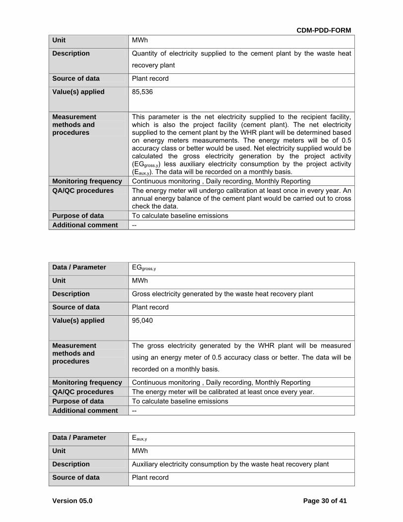
Data / Parameter EGi,j,y
CDM-PDD-FORM
Version 05.0 Page 30 of 41
Unit MWh
Description Quantity of electricity supplied to the cement plant by the waste heat
recovery plant
Source of data Plant record
Value(s) applied 85,536
Measurement methods and procedures
This parameter is the net electricity supplied to the recipient facility, which is also the project facility (cement plant). The net electricity supplied to the cement plant by the WHR plant will be determined based on energy meters measurements. The energy meters will be of 0.5 accuracy class or better would be used. Net electricity supplied would be calculated the gross electricity generation by the project activity (EGgross,y) less auxiliary electricity consumption by the project activity (Eaux,y). The data will be recorded on a monthly basis.
Monitoring frequency Continuous monitoring , Daily recording, Monthly Reporting QA/QC procedures The energy meter will undergo calibration at least once in every year. An
annual energy balance of the cement plant would be carried out to cross check the data.
Purpose of data To calculate baseline emissions Additional comment --
Data / Parameter EGgross,y
Unit MWh
Description Gross electricity generated by the waste heat recovery plant
Source of data Plant record
Value(s) applied 95,040
Measurement methods and procedures
The gross electricity generated by the WHR plant will be measured
using an energy meter of 0.5 accuracy class or better. The data will be
recorded on a monthly basis.
Monitoring frequency Continuous monitoring , Daily recording, Monthly Reporting QA/QC procedures The energy meter will be calibrated at least once every year. Purpose of data To calculate baseline emissions Additional comment --
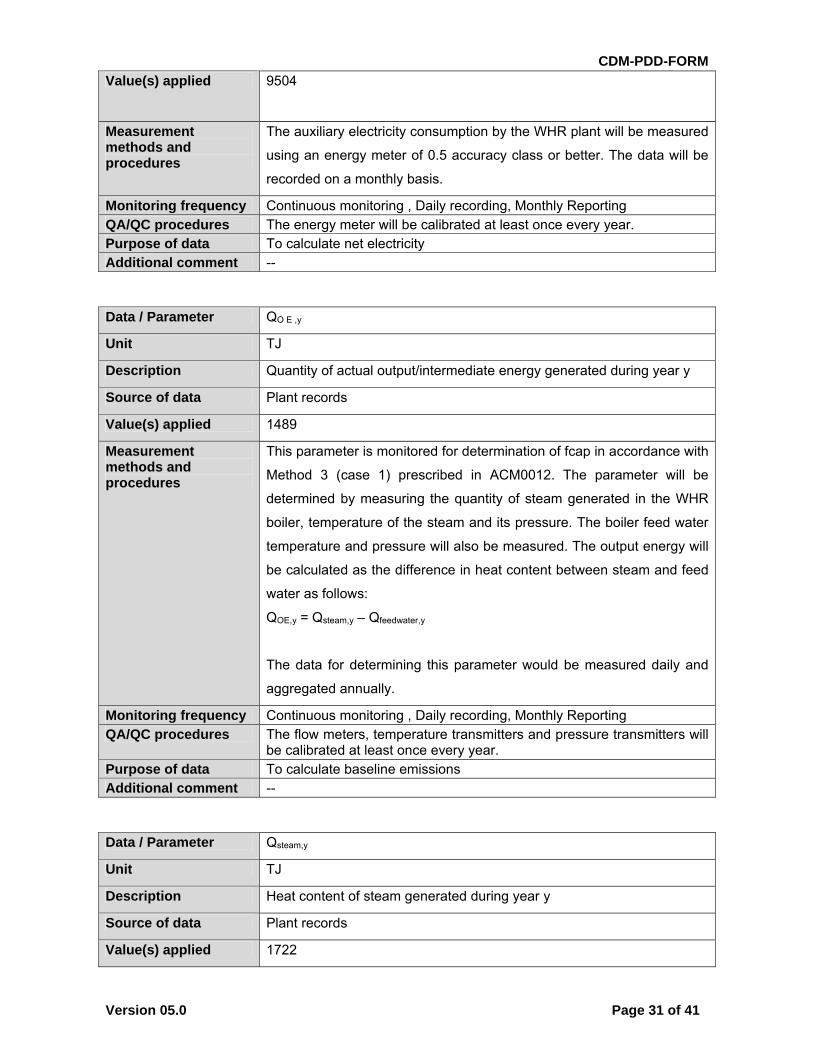
Data / Parameter Eaux,y
Unit MWh
Description Auxiliary electricity consumption by the waste heat recovery plant
Source of data Plant record
CDM-PDD-FORM
Version 05.0 Page 31 of 41
Value(s) applied 9504
Measurement methods and procedures
The auxiliary electricity consumption by the WHR plant will be measured
using an energy meter of 0.5 accuracy class or better. The data will be
recorded on a monthly basis.
Monitoring frequency Continuous monitoring , Daily recording, Monthly Reporting QA/QC procedures The energy meter will be calibrated at least once every year. Purpose of data To calculate net electricity Additional comment --
Data / Parameter QO E ,y
Unit TJ
Description Quantity of actual output/intermediate energy generated during year y
Source of data Plant records
Value(s) applied 1489
Measurement methods and procedures
This parameter is monitored for determination of fcap in accordance with
Method 3 (case 1) prescribed in ACM0012. The parameter will be
determined by measuring the quantity of steam generated in the WHR
boiler, temperature of the steam and its pressure. The boiler feed water
temperature and pressure will also be measured. The output energy will
be calculated as the difference in heat content between steam and feed
water as follows:
QOE,y = Qsteam,y – Qfeedwater,y
The data for determining this parameter would be measured daily and
aggregated annually.
Monitoring frequency Continuous monitoring , Daily recording, Monthly Reporting QA/QC procedures The flow meters, temperature transmitters and pressure transmitters will
be calibrated at least once every year. Purpose of data To calculate baseline emissions Additional comment --
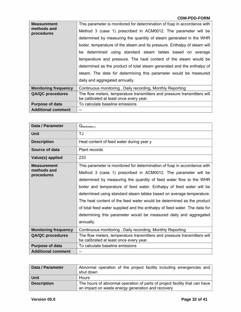
Data / Parameter Qsteam,y
Unit TJ
Description Heat content of steam generated during year y
Source of data Plant records
Value(s) applied 1722
CDM-PDD-FORM
Version 05.0 Page 32 of 41
Measurement methods and procedures
This parameter is monitored for determination of fcap in accordance with
Method 3 (case 1) prescribed in ACM0012. The parameter will be
determined by measuring the quantity of steam generated in the WHR
boiler, temperature of the steam and its pressure. Enthalpy of steam will
be determined using standard steam tables based on average
temperature and pressure. The heat content of the steam would be
determined as the product of total steam generated and the enthalpy of
steam. The data for determining this parameter would be measured
daily and aggregated annually.
Monitoring frequency Continuous monitoring , Daily recording, Monthly Reporting QA/QC procedures The flow meters, temperature transmitters and pressure transmitters will
be calibrated at least once every year. Purpose of data To calculate baseline emissions Additional comment --
Data / Parameter Qfeedwater,y
Unit TJ
Description Heat content of feed water during year y
Source of data Plant records
Value(s) applied 233
Measurement methods and procedures
This parameter is monitored for determination of fcap in accordance with
Method 3 (case 1) prescribed in ACM0012. The parameter will be
determined by measuring the quantity of feed water flow to the WHR
boiler and temperature of feed water. Enthalpy of feed water will be
determined using standard steam tables based on average temperature.
The heat content of the feed water would be determined as the product
of total feed water supplied and the enthalpy of feed water. The data for
determining this parameter would be measured daily and aggregated
annually.
Monitoring frequency Continuous monitoring , Daily recording, Monthly Reporting QA/QC procedures The flow meters, temperature transmitters and pressure transmitters will
be calibrated at least once every year. Purpose of data To calculate baseline emissions Additional comment --
Data / Parameter Abnormal operation of the project facility including emergencies and shut down
Unit Hours Description The hours of abnormal operation of parts of project facility that can have
an impact on waste energy generation and recovery
CDM-PDD-FORM
Version 05.0 Page 33 of 41
Source of data Plant records Value(s) applied 0 Measurement methods and procedures
The abnormal hours of operation would be determined as follows: Shut down periods of the respective units / kilns would be
recorded in logbooks Periods of abnormal loads of the respective units / kilns would be
recorded in logbooks Any major maintenance activities of waste heat recovery power
plant or kilns would be recorded in logbooks The data would be monitored on a daily basis and annual aggregated records would be maintained.
Monitoring frequency Continuous monitoring , Daily recording, Monthly Reporting QA/QC procedures -- Purpose of data To check the efficiency of project activity during project operation Additional comment --
B.7.2. Sampling plan
>> There is no sampling plan.
B.7.3. Other elements of monitoring plan
>> JKLCL has an established environmental management and monitoring cell. The monitoring
activities pertaining to the project would fall under purview of Environmental management cell.
Following diagram shows the reporting structure of this cell.
All data collected as part of monitoring plan should be archived electronically and be kept at least
for 2 years after the end of the last crediting period. 100% of the data should be monitored if not
indicated otherwise in the comments in the tables below.
JKLCL is an ISO-9001 as well as ISO-14001 company. The parameters are monitored by the
operator according to procedure prescribed in ISO manual. The parameters will be monitored and
logged log sheets (which is a controlled ISO document). Based on the logged data and recorded in
panel log sheets, a report consisting of above parameters will be prepared by Shift in charge in soft
copy and will be forwarded to CDM Coordinator through email on monthly basis. The report
received from the respective department through e-mail or hard copies will be compiled by
Coordinator, CDM. The reports will be retained till 2 years after the end of crediting period or the
last issuance of CERs for this project activity, whichever occurs later. A CDM manual is prepared,
which illustrates the detailed roles and responsibilities of individuals involved in project activity.
To ascertain the Quality Control and Quality Assurance of the monitored parameters following
procedure is adopted:
The data used will be reviewed by conducting a inter department review meeting once in 6
months. The Coordinator CDM will discuss the data (received from respective departments)
with CDM Team member of concerned departments. Once the data is compiled and
checked, it will be handed over to Verifier (JKLCL official) for Verification. After data
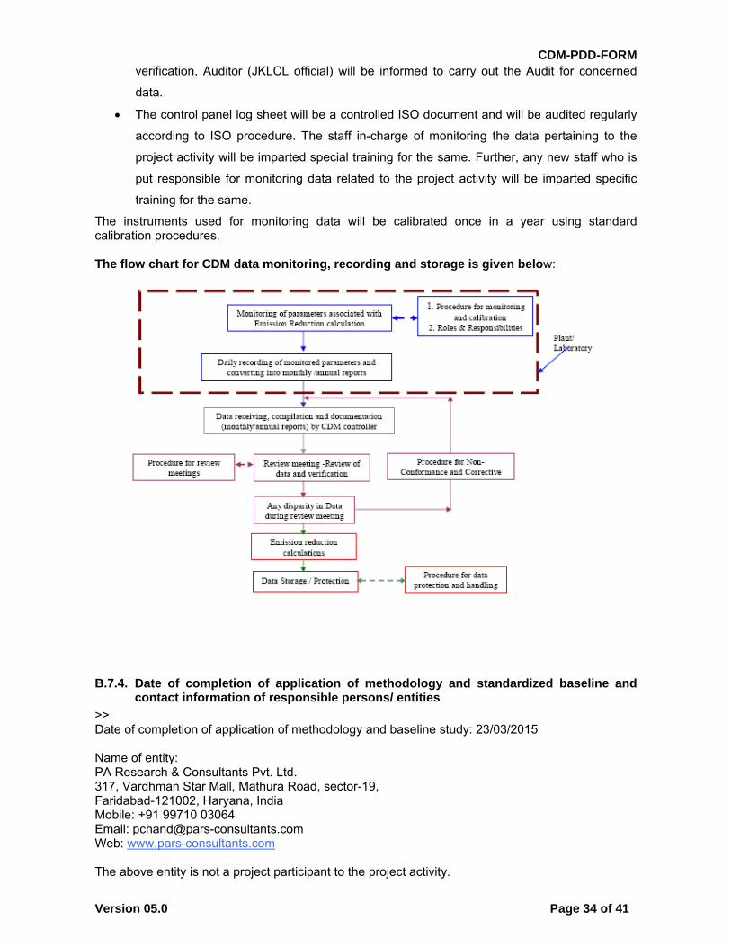
CDM-PDD-FORM
Version 05.0 Page 34 of 41
verification, Auditor (JKLCL official) will be informed to carry out the Audit for concerned
data.
The control panel log sheet will be a controlled ISO document and will be audited regularly
according to ISO procedure. The staff in-charge of monitoring the data pertaining to the
project activity will be imparted special training for the same. Further, any new staff who is
put responsible for monitoring data related to the project activity will be imparted specific
training for the same.
The instruments used for monitoring data will be calibrated once in a year using standard calibration procedures. The flow chart for CDM data monitoring, recording and storage is given below:
B.7.4. Date of completion of application of methodology and standardized baseline and contact information of responsible persons/ entities
>> Date of completion of application of methodology and baseline study: 23/03/2015 Name of entity: PA Research & Consultants Pvt. Ltd. 317, Vardhman Star Mall, Mathura Road, sector-19, Faridabad-121002, Haryana, India Mobile: +91 99710 03064 Email: [email protected] Web: www.pars-consultants.com The above entity is not a project participant to the project activity.
CDM-PDD-FORM
Version 05.0 Page 35 of 41
SECTION C. Duration and crediting period
C.1. Duration of project activity
C.1.1. Start date of project activity
>> 29/03/2009 (date of signing of agreement with the technology supplier)
C.1.2. Expected operational lifetime of project activity
>> 20 years 00 months
C.2. Crediting period of project activity
C.2.1. Type of crediting period
>> Fixed crediting period
C.2.2. Start date of crediting period
>> 15/06/2015 (or the date of registration with UNFCCC whichever is later)
C.2.3. Length of crediting period
10 years 00 months
SECTION D. Environmental impacts
D.1. Analysis of environmental impacts
>> The project activity displaces Power from Grid connected power plants and would reduce emissions like carbon dioxide, sulphur oxides, nitrogen oxides and other local pollutants. It would also marginally lead to conservation of the natural resource. These aspects would contribute to the regional and global environmental benefits. The following phases of the project implementation have been considered to assess the environmental impacts of the project activity:
During Construction Phase During Operation and Maintenance Phase
Construction Phase Taking into consideration the project life cycle, the environmental impacts during construction phase are negligible and exist for a shorter period of time till the end of construction phase. Therefore, it would have a negligible impact on local environment. Operation and Maintenance Phase The environmental, social and other associated impacts of the project activity, evident during the operation and maintenance phase are as follows.
Impact on Air Environment Project activity would have no negative impact on the ambient air quality of the project site. Fugitive emission in the work place would be suppressed by occasional water sprinkling in and around the project implementation area. The plant and process area would be designed in such a way that the work environment has dust loading lesser than permissible limits from the process equipment, thereby maintaining safe work place environment. Electrostatic Precipitator would collect the dust from the AQC exit gas after passing through the WHR boilers and discharge the dust into the hopper from where it would be collected and utilised in the cement manufacturing

CDM-PDD-FORM
Version 05.0 Page 36 of 41
process. The flue gas from ESP would be vented to the atmosphere through a stack at adequate ‘stack height’ as per Pollution Control Board norms.
Thermal Pollution In absence of the project activity there would have been considerable amount of thermal pollution in the vicinity due to pet coke based fuel burning. The project activity would utilize the heat content of the exit waste gases and thereby take care of thermal pollution. Work environment pollution due to thermal radiation would not be significant.
Noise Generation Efficient designs have been considered to keep the noise pollution from turbine, fans, centrifugal pumps, electric motors etc. below the permissible level. Noise from safety valves, start up vents, steam jet ejectors of condenser etc. would be reduced by providing silencers at the outlet of the downstream piping. Signboards would be provided at all high noise zone for employee’s notification to take personal protection before entering into the zone.
Impact on Water Environment Wastewater generated would be used for dust suppression in the power production facility.
Solid Waste Management A Waste Heat Recovery based Captive Power Plant would not have any significant effects as regards solid waste generation.
Safety Management The company’s operations are managed with high safety level systems. This includes equipment shutdown procedure, use of personal protective equipments like safety helmets, safety shoes, safety belts, ear plugs, nose mask, hand gloves, aprons, asbestos suits, safety awareness, emergency response plan, mock drills, training on use of fire fighting equipment etc. For ensuring safety of the workmen all moving parts of all machinery and exposed parts of machines would be provided with guards and hoods and all the surfaces likely to attain high temperatures would be duly insulated. The other important aspects of checking up and maintaining all the machineries properly and continuously shall be ensured by the facility. Production does not involve generation and handling of any hazardous by-products. Conclusion The project activity would undertake all necessary environmental pollution abatement measures with periodical monitoring.
D.2. Environmental impact assessment
>> The environmental impacts are not considered significant by the host country and hence it does not require the project participant to undertake an EIA study and seek prior environmental clearance. As per the EIA notification 2009 (http://envfor.nic.in/legis/eia/so195.pdf), WHR project do not fall under the ambit of project that need EIA to be carried out. The project participant plans to implement the project activity as it aids in promoting sustainability. Article 12 of the Kyoto Protocol also requires that a CDM project activity contributes to the sustainable development of the host country. Assessing the project activity’s positive and negative impacts on the local environment and on society is thus key element for each CDM project. The project activity results in reduction of petroleum coke consumption in the existing power plant. With reduced petroleum coke consumption, the negative environmental impacts related to fossil fuel combustion, particularly the release of SOx, NOx and other contaminants would be avoided. Hence the project activity would help in improving the ambient air quality. The project activity would also help in preserving the fast depleting conventional fossil fuels reserves of the nation and make it available for other essential activities. The GHG emission reductions due to the project activity, benefits the global environment which in turn is a step towards sustainability. The project activity does not involve water consumption and will not lead to generation of effluents. JKLCL plans to undertake measures to minimize the noise pollution due to the project activity and the same would be addressed during the design stage.
CDM-PDD-FORM
Version 05.0 Page 37 of 41
SECTION E. Local stakeholder consultation
E.1. Solicitation of comments from local stakeholders
>> Stakeholders have been identified on the basis of their involvement at various stages of project activity. The list of relevant stakeholders includes all the organizations, which were/ would be communicated / applied to get necessary clearances. The stakeholders identified for the project are as under:
Local population Employees of JKLCL Ministry of Environment & Forest (MoEF), Government of India, the DNA. Rajasthan State Pollution Control Board.
The stakeholders were invited via invitation letters dated 04/11/2009. The stakeholder meeting was held on 19/11/2009 on JKLCL premises in Sirohi, Rajasthan.
E.2. Summary of comments received
>> The stakeholders were unanimous in their opinion that the proposed project is extremely beneficial from a sustainable development point of view. They expressed concern about the impact that the project would have on the local flora. The stakeholders were also interested about the employment opportunities that would arise from the project activity. Occupational health hazard was also an area where the stakeholders expressed concern.
E.3. Report on consideration of comments received
>> The project being a waste heat recovery project located entirely on the plant premises would not have any effect on the local flora, still, an environmental management plan has been put into place to further mitigate the effect of the project on the local environment. The proposed project would also not have any occupational hazard as it is a waste heat recovery project, proper protective equipment would be provided to all the workers on the plant premises. During the construction as well as operation phase of the project, as far as possible, local manpower will be employed.
SECTION F. Approval and authorization >> The project activity has been granted Host country approval (Ref. No. 1618-09) by DNA of India.
- - - - -
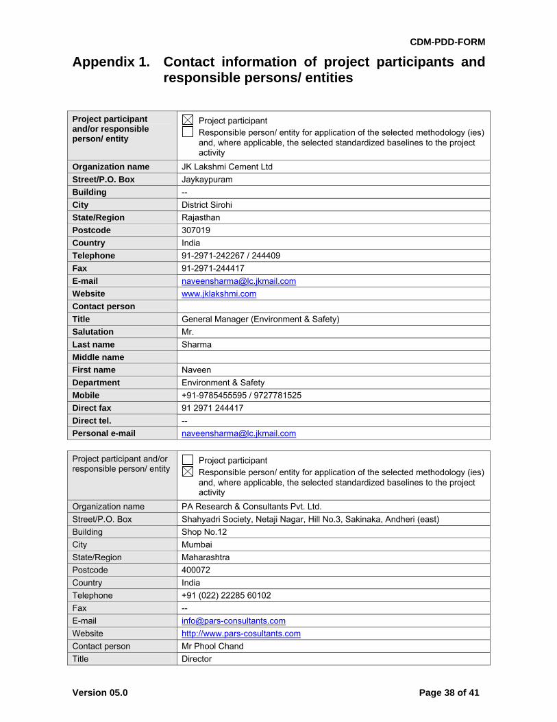
CDM-PDD-FORM
Version 05.0 Page 38 of 41
Appendix 1. Contact information of project participants and responsible persons/ entities
Project participant and/or responsible person/ entity
Project participant Responsible person/ entity for application of the selected methodology (ies)
and, where applicable, the selected standardized baselines to the project activity
Organization name JK Lakshmi Cement Ltd
Street/P.O. Box Jaykaypuram
Building --
City District Sirohi
State/Region Rajasthan
Postcode 307019
Country India
Telephone 91-2971-242267 / 244409
Fax 91-2971-244417
E-mail [email protected]
Website www.jklakshmi.com
Contact person
Title General Manager (Environment & Safety)
Salutation Mr.
Last name Sharma
Middle name
First name Naveen
Department Environment & Safety
Mobile +91-9785455595 / 9727781525
Direct fax 91 2971 244417
Direct tel. --
Personal e-mail [email protected]
Project participant and/or responsible person/ entity
Project participant Responsible person/ entity for application of the selected methodology (ies)
and, where applicable, the selected standardized baselines to the project activity
Organization name PA Research & Consultants Pvt. Ltd.
Street/P.O. Box Shahyadri Society, Netaji Nagar, Hill No.3, Sakinaka, Andheri (east)
Building Shop No.12
City Mumbai
State/Region Maharashtra
Postcode 400072
Country India
Telephone +91 (022) 22285 60102
Fax --
E-mail [email protected]
Website http://www.pars-cosultants.com
Contact person Mr Phool Chand
Title Director
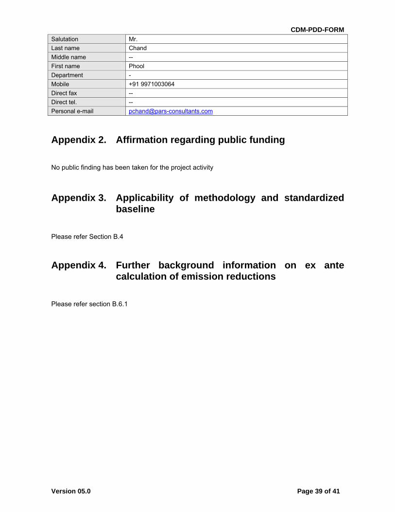
CDM-PDD-FORM
Version 05.0 Page 39 of 41
Salutation Mr.
Last name Chand
Middle name --
First name Phool
Department -
Mobile +91 9971003064
Direct fax --
Direct tel. --
Personal e-mail [email protected]
Appendix 2. Affirmation regarding public funding
No public finding has been taken for the project activity
Appendix 3. Applicability of methodology and standardized baseline
Please refer Section B.4
Appendix 4. Further background information on ex ante calculation of emission reductions
Please refer section B.6.1
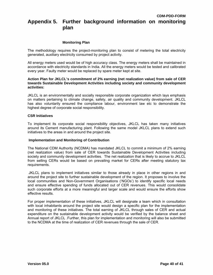
CDM-PDD-FORM
Version 05.0 Page 40 of 41
Appendix 5. Further background information on monitoring plan
Monitoring Plan
The methodology requires the project-monitoring plan to consist of metering the total electricity generated, auxiliary electricity consumed by project activity.
All energy meters used would be of high accuracy class. The energy meters shall be maintained in accordance with electricity standards in India. All the energy meters would be tested and calibrated every year. Faulty meter would be replaced by spare meter kept at site.
Action Plan for JKLCL’s commitment of 2% earning (net realization value) from sale of CER towards Sustainable Development Activities including society and community development activities:
JKLCL is an environmentally and socially responsible corporate organization which lays emphasis on matters pertaining to climate change, safety, air quality and community development. JKLCL has also voluntarily ensured the compliance labour, environment law etc to demonstrate the highest degree of corporate social responsibility.
CSR Initiatives
To implement its corporate social responsibility objectives, JKLCL has taken many initiatives around its Cement manufacturing plant. Following the same model JKLCL plans to extend such initiatives to the areas in and around the project site.
Implementation and Monitoring of Contribution
The National CDM Authority (NCDMA) has mandated JKLCL to commit a minimum of 2% earning (net realization value) from sale of CER towards Sustainable Development Activities including society and community development activities. The net realization that is likely to accrue to JKLCL from selling CERs would be based on prevailing market for CERs after meeting statutory tax requirements.
JKLCL plans to implement initiatives similar to those already in place in other regions in and around the project site to further sustainable development of the region. It proposes to involve the local communities and Non-Government Organisations (‘NGOs’) to identify specific local needs and ensure effective spending of funds allocated out of CER revenues. This would consolidate such corporate efforts at a more meaningful and larger scale and would ensure the efforts show effective results.
For proper implementation of these initiatives, JKLCL will designate a team which in consultation with local inhabitants around the project site would design a specific plan for the implementation and monitoring of these initiatives. The total earning of JKLCL through sales of CER and actual expenditure on the sustainable development activity would be verified by the balance sheet and Annual report of JKLCL .Further, this plan for implementation and monitoring will also be submitted to the NCDMA at the time of realization of CER revenues through the sale of CER.
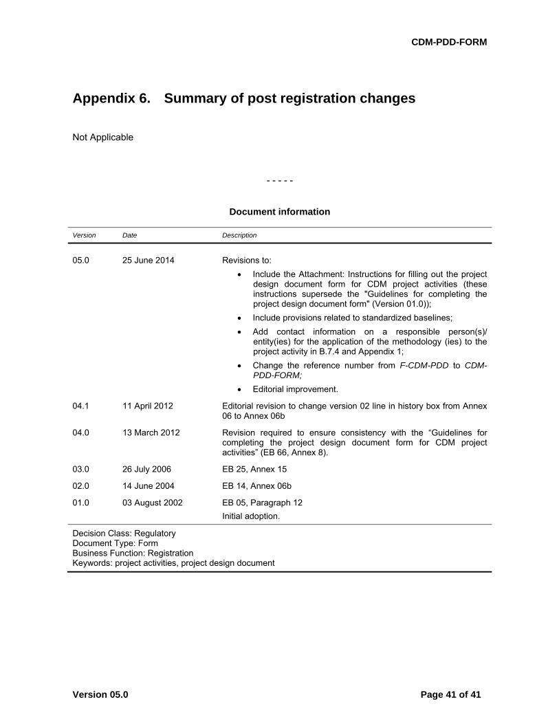
CDM-PDD-FORM
Version 05.0 Page 41 of 41
Appendix 6. Summary of post registration changes
Not Applicable
- - - - -
Document information
Version Date Description
05.0 25 June 2014 Revisions to:
Include the Attachment: Instructions for filling out the project design document form for CDM project activities (these instructions supersede the "Guidelines for completing the project design document form" (Version 01.0));
Include provisions related to standardized baselines;
Add contact information on a responsible person(s)/ entity(ies) for the application of the methodology (ies) to the project activity in B.7.4 and Appendix 1;
Change the reference number from F-CDM-PDD to CDM-PDD-FORM;
Editorial improvement.
04.1 11 April 2012 Editorial revision to change version 02 line in history box from Annex 06 to Annex 06b
04.0 13 March 2012 Revision required to ensure consistency with the “Guidelines for completing the project design document form for CDM project activities” (EB 66, Annex 8).
03.0 26 July 2006 EB 25, Annex 15
02.0 14 June 2004 EB 14, Annex 06b
01.0 03 August 2002 EB 05, Paragraph 12
Initial adoption.
Decision Class: Regulatory Document Type: Form Business Function: Registration Keywords: project activities, project design document