project final report - cordis.europa.eu · the air preheater and the chp heat ... plant components...
TRANSCRIPT
PROJECT FINAL REPORT
Grant Agreement number: 256694
Project acronym: LOTUS
Project title: Low Temperature Solid Oxide Fuel Cel ls for micro-CHP applications
Funding Scheme: CP
Period covered: from 1-1-2011 to 30-6-2014
Name, title and organisation of the scientific repr esentative of the project's coordinator: E.K. de wit, CTO, HyGear Fuel Cell systems
Tel: +31 88 9494306
Fax: +31 88 9494 399
E-mail:ellart.de [email protected]
Project website address: www.lotus-project.eu

2
4.1 Final publishable summary report
Content
1
4.1 Final publishable summary report 2
Executive summary 3
Summary description of project context and objectives 4
For specific information from the work packages can be obtained from the coordinator: 6
HyGear Fuel Cell Systems 6
Description of the main S&T results/foregrounds 7
WP 2 Low Temperature Stack Implementation 7
WP3 System design & modelling 14
WP4 System engineering 21
WP5: Prototyping 29
WP6 Testing 31
The potential impact (including the socio-economic impact and the wider societal implications of the project so far) and the main dissemination activities and exploitation of results 34
Market Impact 34
Technology Impact 35
Dissemination activities 36
4.2 Use and dissemination of foreground Fout! Bladwijzer niet gedefinieerd.
4.3 Report on societal implications Fout! Bladwijzer niet gedefinieerd.
3
Executive summary The LOTUS system is a 1kWe micro CHP system based on low temperature SOFC technology. The system has
been developed by a consortium of 6 partners under coordination of HyGear fuel cell systems (NL).
SOFCpower (I) and the university of Perugia (I) developed the stack technology. IKTS (D) has performed static
and dynamic system modeling based on which HyGear and Domel (Sl) designed hardware for the fuel
processor and system. The joint research centre of the EU (B) develops test plans for stack- and single cell
testing.
The objectives of the project are to develop, build and test a micro-CHP system with high electrical and
overall efficiency. Focus was on cost reduction and reliability improvements. This was to be achieved by
reducing the SOFC stack temperature down to 650C. Avoiding high temperatures will increase the reliability
of the modules and decrease the operational cost..
System model calculation together with technical requirements lead to the decision to only partly reform the
natural gas feed into hydrogen rich reformate before entering the stack. The other half of the feed is
internally reformed in the stack to increase efficiency. Reduction of parts reduces costs and increases the
reliability. Within the LOTUS project the number of blowers was reduced to one, by developing a new dual
stage blower. The start-up burner and anode tail-gas burner were combined into one as well. SOFC power
developed new stack materials, which have an improved performance at the desired temperatures, meeting
all specifications. The materials were tested at the SOFCpower and at the university of Perugia in a round
robin test. Short stack and real stack testing were performed and stacks were shipped to JRC and HyGear for
testing in a stack test station and in the LOTUS system. At HyGear the fuel processing hardware is designed
and built. An air pre-heater and the CHP heat exchanger is commercially acquired. The reformer and steam
generator are HyGear designed based on the compact heat exchangers combined with commercial steam
reforming catalyst.
The LOTUS system was constructed in the HyGear facilities and a suitable test environment was created in
which the system could be tested safely. During the testing it appeared that the new system design with
single blower and under-pressure operation poses additional requirements on the stack and system design.
Any small leakages of air into the stack by under pressure operation leads to a lower operation stack
temperature and too lean burning of ATO burner.
Measurement data were not conclusive for efficiency determinations. Model calculations predict an
electrical efficiency of 43% and total efficiency of 80%. The results of the project show that the overall
system complexity was reduced and all modules (reformer, stack, burner, and blower) were successfully
developed and tested. The overall system was successfully operated. Due to failure of the stack no efficiency
data could be collected.
The cost outlook of the system at low series production levels are predicted to be €4,745 on target for
commercial introduction.
4
Summary description of project context and objectives
The LOTUS project is formed around a consortium of 6 partners working on the development, construction
and testing of a 1kWe micro CHP system based on SOFC fuel cell stack technology operating at lower
temperatures than usual. The consortium is build around stack manufacturer SOFCpower (I) who together
with the university of Perugia (I) and the Joint Research Centre (B) develop and test fuel cell components
ranging from single cells up to full stacks for implementation in a micro-CHP system. IKTS (Fraunhofer
institute) (D), HyGear Fuel Cell systems (NL) and Domel (Sl) work on the modeling, development and
construction of a prototype of the system in which the gas air delivery system by Domel is an important
module.
One of the main objectives is to build a system which runs using a stack temperature of 650°C. Other project
objectives are:
- Electrical system efficiency is 45%
- Total system efficiency is 80%
- Reduce cost outlook by using mass produced, field proven components
- Develop and integrated system which is suitable for direct replacement of conventional heating
appliances.
The total cost of the system should have an outlook to meet the targets set in the multi-annual
implementation plan of the FCH-JU, which is €5000/kWe in 2020.
The project contains 6 work packages in which a strong cooperation between the six partners is required.
1. Management
2. Stack implementation
3. System modeling
4. System Engineering
5. Prototyping
6. System testing and validation
The first work package called for 6 month meetings of the general assembly to determine progress in the
project. It also took care for managing the grant agreement and the web-site.
In the second work package SOFCpower develops the SOFC cells to a higher performance at lower
temperature. New materials and combinations of materials will be used in the Cells and tested on activity
and durability. Testing of the single cell materials is done in parallel at SOFCpower and at the University of
Perugia. The Joint research centre provides input on the details of the testing procedures. Out of several
5
single cell test the best set of materials will be selected and built into a short stack. This stack is now tested
for performance and longevity. The results of these tests will be used in the assembly of the full 1kWe stack
which will be delivered to JRC for evaluation and to HyGear for introduction in the prototype later during the
project.
In work package 3 the stack data which were to be expected from the stack development are gathered
together with information from fuel processor technologies and customer requirements. All this information
leads to the System requirements document which is used to develop the appropriate technologies for a
system prototype. IKTS builds a steady state model in the first place to calculate he flows, temperatures and
other conditions during nominal power level and during some start up cases. The model data will be used to
develop the hardware and will be validated and updated once real measured data are available. After the
steady state model IKTS will build a dynamic model of the system based on the designs made in the project.
Based on the work package 3 data from IKTS, a P&ID will be created by HyGear Fuel cell systems in
workpackage 4. In this P&ID the modules were defined and analyses for technical opportunities and cost
analysis. Together with partner Domel, a strategy will be developed to decrease the number of blowers to
decrease the number of parts in the system. Domel delivers a prototype with measured data about the
efficiency and performance of the device.
HyGear fuel cell systems will develop hardware for fuel processing in workpackage 4. An important part of
this system is the burner which has a dual function: start up and anode tail gas combustion. This double
functionality makes this a high risk part. Fall back plan is two separate burners.
In parallel to the burner development the specification for the heat exchangers for air preheating, steam
generation and CHP function are extracted from the process model. The air preheater and the CHP heat
exchanger can be sourced commercially, the steam generator will be developed internally at HyGear as this
device has a extended function in mixing natural gas and steam in the same piece of hardware.
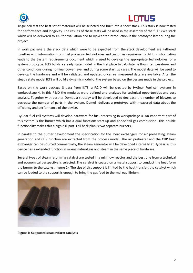
Several types of steam reforming catalyst are tested in a miniflow reactor and the best one from a technical
and economical perspective is selected. The catalyst is coated on a metal support to conduct the heat form
the burner to the catalyst (figure 1). The size of this support is limited by the heat transfer, the catalyst which
can be loaded to the support is enough to bring the gas feed to thermal equilibrium.
Figure 1: Supported steam reform catalysts

6
In work package 5 the hardware developed in the preceding work packages is collected. Also the Balance of
plant components are sourced and the LOTUS system is constructed and ready to be tested.
Finally in work package 6 the LOTUS prototype is tested as a 1kWe micro-CHP system. The prototype is
installed in the laboratory, hooked up the natural gas line, and connected to a hot water tank simulator. The
final objective of the test is to determine the efficiency and validate the models from IKTS, both the start up
cases and the nominal operation point.
For specific information from the work packages can be obtained from the coordinator:
HyGear Fuel Cell Systems
Dick Lieftink
PO box 5280,
6802 EG Arnhem
The Netherlands
Tel: 088-9494300

7
Description of the main S&T results/foregrounds
WP 2 Low Temperature Stack Implementation WP2 activities are divided into 3 tasks, aiming to development of single cells (Task 2.1), developing of short
stacks (Task 2.2) and of large stacks (Task 2.3).
Task 2.1 Development single cells This task deals with cell optimization for low temperature operation. The activity was carried out by both
SOFCpower and University of Perugia. SOFCpower focused on cell development and testing activity, paying
particular attention on cathode and barrier layer optimization; University of Perugia investigated cell
performances by the acquisition of characteristic curve (IV),using the home-made test bench assembled and
provided by SOFCpower, reducing variations coming from test bench and optimizing robin test between the
two laboratories: one of the tasks of the activity was actually a comparison between results obtained in the
two laboratories. A more detailed investigation was done by SOFCpower using Electrochemical Impedance
Spectroscopy (EIS) at OCV and 700 mV.
Cell development
Activity at SOFCpower focused on button cell development, in order to increase cell performances at low
temperature operation (ranging from 650 to 700°C). Actually, SoA SOFCpower cells are designed to work at
intermediate temperatures; for this reason, materials conventionally used for this application are not
suitable for low temperature operation.
In order to improve the electrochemical performances of the cell in the range 650-700°C, alternative
materials have to be considered. Higher contribution to ASR (Area Specific Resistance) is generally coming
from cathode electrode and barrier layer used in between electrode and electrolyte to minimize elemental
diffusion and ohmic degradation due to resistive phase at electrolyte interface.
Figure 1: IV curve of improved cell from 600°C to 700°C
8
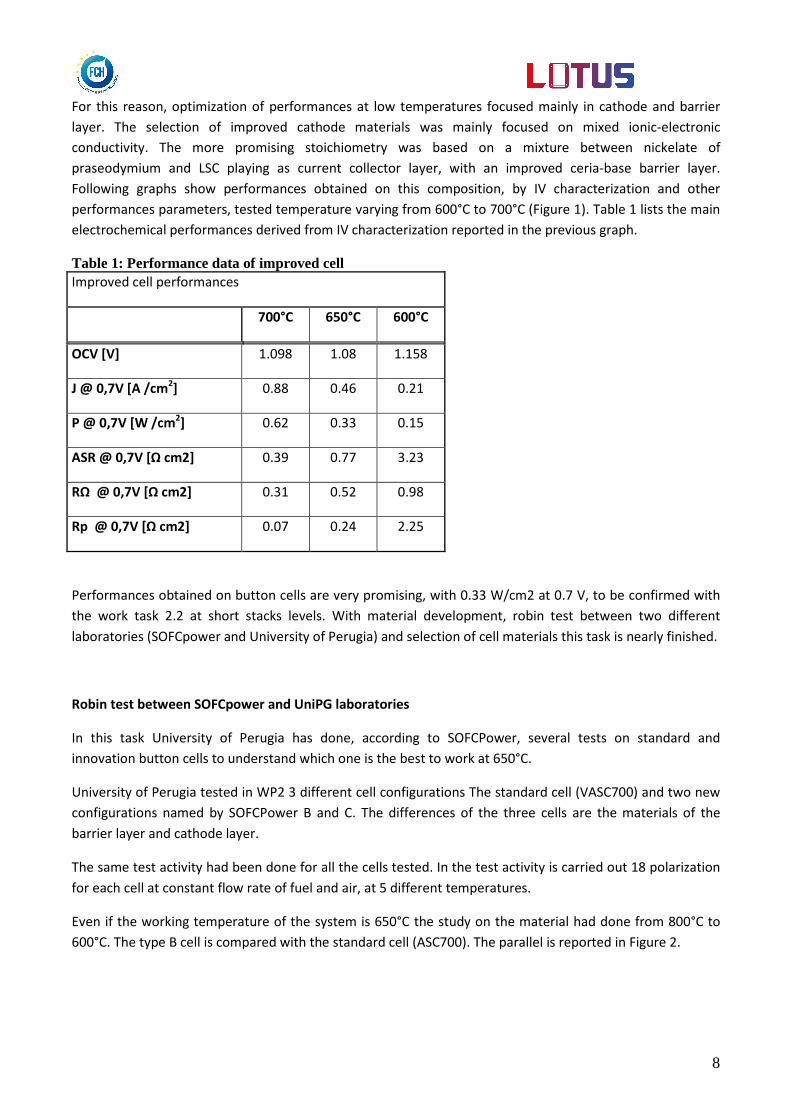
For this reason, optimization of performances at low temperatures focused mainly in cathode and barrier
layer. The selection of improved cathode materials was mainly focused on mixed ionic-electronic
conductivity. The more promising stoichiometry was based on a mixture between nickelate of
praseodymium and LSC playing as current collector layer, with an improved ceria-base barrier layer.
Following graphs show performances obtained on this composition, by IV characterization and other
performances parameters, tested temperature varying from 600°C to 700°C (Figure 1). Table 1 lists the main
electrochemical performances derived from IV characterization reported in the previous graph.
Table 1: Performance data of improved cell Improved cell performances
700°C 650°C 600°C
OCV [V] 1.098 1.08 1.158
J @ 0,7V [A /cm2] 0.88 0.46 0.21
P @ 0,7V [W /cm2] 0.62 0.33 0.15
ASR @ 0,7V [Ω cm2] 0.39 0.77 3.23
RΩ @ 0,7V [Ω cm2] 0.31 0.52 0.98
Rp @ 0,7V [Ω cm2] 0.07 0.24 2.25
Performances obtained on button cells are very promising, with 0.33 W/cm2 at 0.7 V, to be confirmed with
the work task 2.2 at short stacks levels. With material development, robin test between two different
laboratories (SOFCpower and University of Perugia) and selection of cell materials this task is nearly finished.
Robin test between SOFCpower and UniPG laboratories
In this task University of Perugia has done, according to SOFCPower, several tests on standard and
innovation button cells to understand which one is the best to work at 650°C.
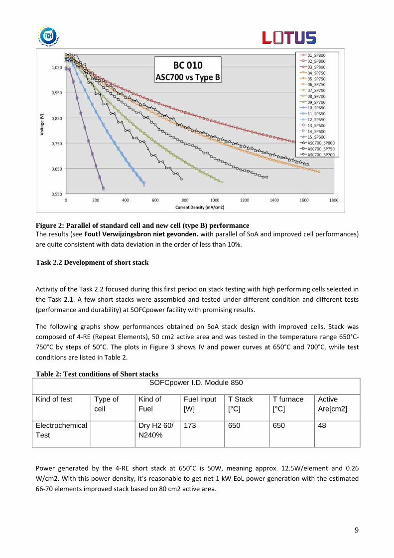
University of Perugia tested in WP2 3 different cell configurations The standard cell (VASC700) and two new
configurations named by SOFCPower B and C. The differences of the three cells are the materials of the
barrier layer and cathode layer.
The same test activity had been done for all the cells tested. In the test activity is carried out 18 polarization
for each cell at constant flow rate of fuel and air, at 5 different temperatures.
Even if the working temperature of the system is 650°C the study on the material had done from 800°C to
600°C. The type B cell is compared with the standard cell (ASC700). The parallel is reported in Figure 2.
9
Figure 2: Parallel of standard cell and new cell (type B) performance The results (see Fout! Verwijzingsbron niet gevonden. with parallel of SoA and improved cell performances)
are quite consistent with data deviation in the order of less than 10%.
Task 2.2 Development of short stack
Activity of the Task 2.2 focused during this first period on stack testing with high performing cells selected in
the Task 2.1. A few short stacks were assembled and tested under different condition and different tests
(performance and durability) at SOFCpower facility with promising results.
The following graphs show performances obtained on SoA stack design with improved cells. Stack was
composed of 4-RE (Repeat Elements), 50 cm2 active area and was tested in the temperature range 650°C-
750°C by steps of 50°C. The plots in Figure 3 shows IV and power curves at 650°C and 700°C, while test
conditions are listed in Table 2.
Table 2: Test conditions of Short stacks SOFCpower I.D. Module 850
Kind of test Type of cell
Kind of Fuel
Fuel Input [W]
T Stack [°C]
T furnace [°C]
Active Are[cm2]
Electrochemical Test
Dry H2 60/ N240%
173 650 650 48
Power generated by the 4-RE short stack at 650°C is 50W, meaning approx. 12.5W/element and 0.26
W/cm2. With this power density, it’s reasonable to get net 1 kW EoL power generation with the estimated
66-70 elements improved stack based on 80 cm2 active area.

10
Higher results were of course given at 700°C, with 0.37 W/cm2 density power. If same performances will be
confirmed at larger stack level, the targeted 1 kW-size stack could be achieved with only 50 elements 80 cm2
active area stack. Stack operational conditions target of 650°C seems to can be therefore fulfilled with stack
Figure 3: 4-RE short stack IV characterization and power generation at 650°C to 700°C
Preliminary endurance test under Lotus conditions (650°C stack temperature) revealed good durability upon
short term (100 hours of operation), with an activation in the first 20 hours followed by a slight degradation.
Current was set to 16A, starting average element potential of 738 mV. Overall behaviour is shown in Figure
4. Test is still running, aimed to study long term stack behaviour.
Figure 4: 4-RE short stack endurance test at 650°C and 16A
11
The work in this task used around 80% of the person months. The last 20% of the resources will be used to
monitor long term test running and data processing.
Task 2.3 Develop and test stack to 1 kWe In the meantime, some experimental activity of UNIPG was also extended to this task 2.2, taking advantage
of the presence of stack test rig in UNIPG laboratory, TB2500. A test was performed to evaluate the
characteristic of a 500W-size stack developed with state of art technology under LOTUS conditions.
The test was performed in a nominal 500 W stack fed with reformed natural gas. The rig gets inlet fuel
directly from the grid and is previously processed outside the test rig where a desulphurizer reactor
eliminate sulphur compounds from the gas flow. The same process will be performed in the final system as
sulphur causes rapid degradation to both the methane reactor and the cell. Natural gas is processed also
inside the test rig in the reactor that enhance steam methane reforming and provides a useful gas stream to
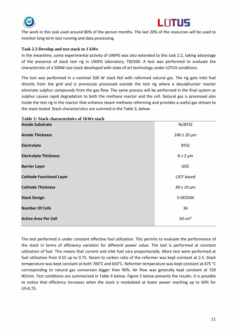
the stack tested. Stack characteristics are summed in the Table 3, below:
Table 3: Stack characteristics of 1kWe stack Anode Substrate Ni/8YSZ
Anode Thickness 240 ± 20 μm
Electrolyte 8YSZ
Electrolyte Thickness 8 ± 2 μm
Barrier Layer GDC
Cathode Functional Layer LSCF based
Cathode Thickness 40 ± 10 μm
Stack Design S-DESIGN
Number Of Cells 36
Active Area Per Cell 50 cm²
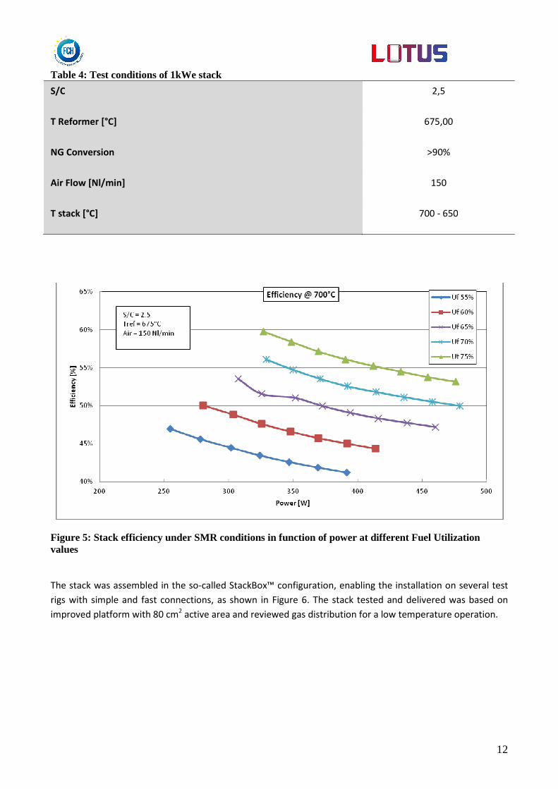
The test performed is under constant effective fuel utilization. This permits to evaluate the performance of
the stack in terms of efficiency variation for different power value. The test is performed at constant
utilization of fuel. This means that current and inlet fuel vary proportionally. More test were performed at
fuel utilization from 0.55 up to 0.75. Steam to carbon ratio of the reformer was kept constant at 2.5. Stack
temperature was kept constant at both 700°C and 650°C. Reformer temperature was kept constant at 675 °C
corresponding to natural gas conversion bigger than 90%. Air flow was generally kept constant at 150
Nl/min. Test conditions are summarized in Table 4 below. Figure 5 below presents the results. It is possible
to notice that efficiency increases when the stack is modulated at lower power reaching up to 60% for
Uf=0.75.
12
Table 4: Test conditions of 1kWe stack
S/C 2,5
T Reformer [°C] 675,00
NG Conversion >90%
Air Flow [Nl/min] 150
T stack [°C] 700 - 650
Figure 5: Stack efficiency under SMR conditions in function of power at different Fuel Utilization values
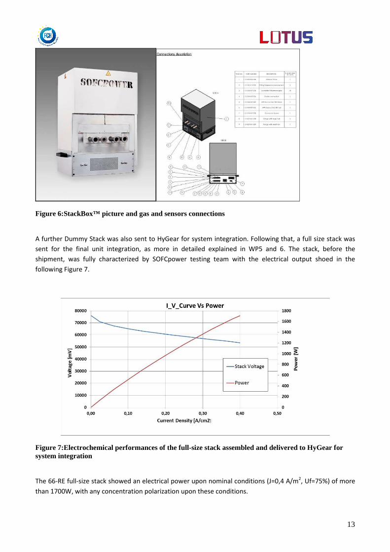
The stack was assembled in the so-called StackBox™ configuration, enabling the installation on several test
rigs with simple and fast connections, as shown in Figure 6. The stack tested and delivered was based on
improved platform with 80 cm2 active area and reviewed gas distribution for a low temperature operation.
13
Figure 6:StackBox™ picture and gas and sensors connections
A further Dummy Stack was also sent to HyGear for system integration. Following that, a full size stack was
sent for the final unit integration, as more in detailed explained in WP5 and 6. The stack, before the
shipment, was fully characterized by SOFCpower testing team with the electrical output shoed in the
following Figure 7.
Figure 7:Electrochemical performances of the full-size stack assembled and delivered to HyGear for system integration
The 66-RE full-size stack showed an electrical power upon nominal conditions (J=0,4 A/m2, Uf=75%) of more
than 1700W, with any concentration polarization upon these conditions.

14
WP3 System design & modelling The work package 3 titled as “System Design and Modelling” is managed by Fraunhofer IKTS based on
particular input from WP2 and WP4.
Task 3.1 SRD The creation of the system requirement definition (SRD) document was organised by IKTS. A top-down
approach was intended, including identification of requirements and boundary conditions. The University of
Perugia shared load profile analysis for sample households. Information of current market developments
was given by HyGear, based on prior discussion with the associated partner Vaillant. It was agreed to
consider the SRD-document as a development basis to be extended and revised also after the SRD meeting.
The main decisions on system specification can be summarized as follows:
• Heat controlled operation of the system is intended,
• System operation shall be based on common natural gas,
• Maximum net power capability of the system (BOL) is set to 1 kWel,
• A high system efficiency is required with the electrical efficiency valued highest,
• Stack operating temperature is set to 650°C,
• The Core Module (see Figure 8) shall contain the SOFC stack and all required peripheral components
for its safe and stable operation,
• The LOTUS prototype shall demonstrate a steady state operating endurance of 1000 h.
ReformerSOFC
Stack
Tail Gas
Oxidiser
InverterStart-up
Burner
Actuators,
BOP
Fuel
Air
Heat
Electricity
Exhaust
Water
Internal Heat Exchange & Storage Network
Figure 8: Schematic of the principle architecture of the SOFC Core Module
15
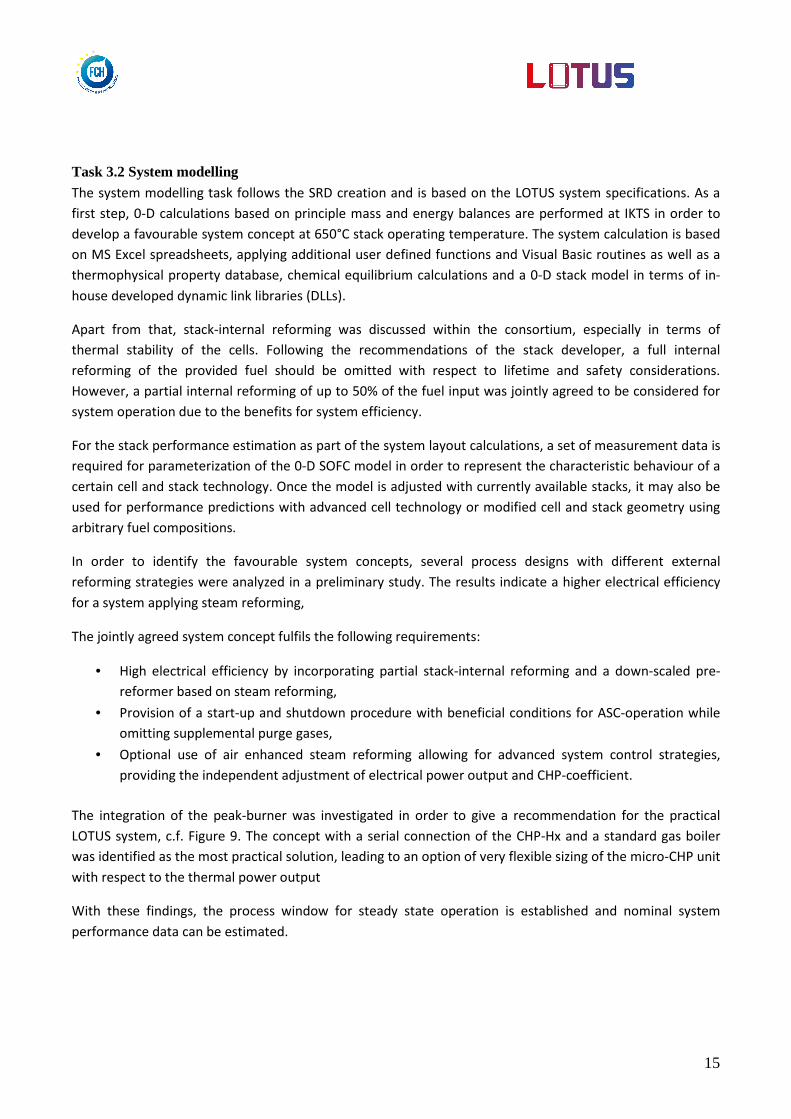
Task 3.2 System modelling The system modelling task follows the SRD creation and is based on the LOTUS system specifications. As a
first step, 0-D calculations based on principle mass and energy balances are performed at IKTS in order to
develop a favourable system concept at 650°C stack operating temperature. The system calculation is based
on MS Excel spreadsheets, applying additional user defined functions and Visual Basic routines as well as a
thermophysical property database, chemical equilibrium calculations and a 0-D stack model in terms of in-
house developed dynamic link libraries (DLLs).
Apart from that, stack-internal reforming was discussed within the consortium, especially in terms of
thermal stability of the cells. Following the recommendations of the stack developer, a full internal
reforming of the provided fuel should be omitted with respect to lifetime and safety considerations.
However, a partial internal reforming of up to 50% of the fuel input was jointly agreed to be considered for
system operation due to the benefits for system efficiency.
For the stack performance estimation as part of the system layout calculations, a set of measurement data is
required for parameterization of the 0-D SOFC model in order to represent the characteristic behaviour of a
certain cell and stack technology. Once the model is adjusted with currently available stacks, it may also be
used for performance predictions with advanced cell technology or modified cell and stack geometry using
arbitrary fuel compositions.
In order to identify the favourable system concepts, several process designs with different external
reforming strategies were analyzed in a preliminary study. The results indicate a higher electrical efficiency
for a system applying steam reforming,
The jointly agreed system concept fulfils the following requirements:
• High electrical efficiency by incorporating partial stack-internal reforming and a down-scaled pre-
reformer based on steam reforming,
• Provision of a start-up and shutdown procedure with beneficial conditions for ASC-operation while
omitting supplemental purge gases,
• Optional use of air enhanced steam reforming allowing for advanced system control strategies,
providing the independent adjustment of electrical power output and CHP-coefficient.
The integration of the peak-burner was investigated in order to give a recommendation for the practical
LOTUS system, c.f. Figure 9. The concept with a serial connection of the CHP-Hx and a standard gas boiler
was identified as the most practical solution, leading to an option of very flexible sizing of the micro-CHP unit
with respect to the thermal power output
With these findings, the process window for steady state operation is established and nominal system
performance data can be estimated.

16
Figure 9: Process flow diagram with suggested peak-burner integration
Figure 10: LOTUS system performance estimation based on the process layout calculation
The coupling of all the relevant system components and iterative balancing of thermal and substance flows
provides a steady-state model of the final system, using MS Excel and in-house functions as technical basis.
An exemplary Sankey-diagram illustrates the estimated system performance at rated power output, see
Figure 10. Based on the stationary system model, a number of special operational modes were investigated,
such as start-up procedure, part-load operation, hot stand-by and inverter flip. Figure 11 indicates 3.5 kW
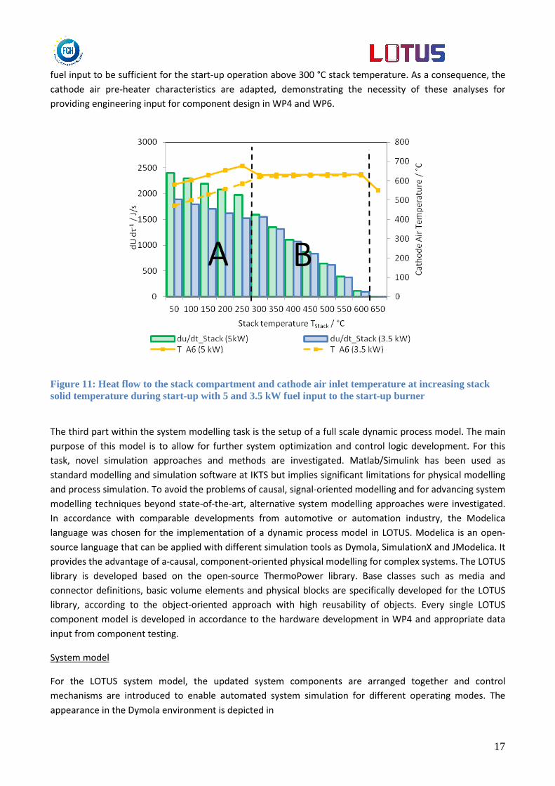
17
fuel input to be sufficient for the start-up operation above 300 °C stack temperature. As a consequence, the
cathode air pre-heater characteristics are adapted, demonstrating the necessity of these analyses for
providing engineering input for component design in WP4 and WP6.
Figure 11: Heat flow to the stack compartment and cathode air inlet temperature at increasing stack solid temperature during start-up with 5 and 3.5 kW fuel input to the start-up burner
The third part within the system modelling task is the setup of a full scale dynamic process model. The main
purpose of this model is to allow for further system optimization and control logic development. For this
task, novel simulation approaches and methods are investigated. Matlab/Simulink has been used as
standard modelling and simulation software at IKTS but implies significant limitations for physical modelling
and process simulation. To avoid the problems of causal, signal-oriented modelling and for advancing system
modelling techniques beyond state-of-the-art, alternative system modelling approaches were investigated.
In accordance with comparable developments from automotive or automation industry, the Modelica
language was chosen for the implementation of a dynamic process model in LOTUS. Modelica is an open-
source language that can be applied with different simulation tools as Dymola, SimulationX and JModelica. It
provides the advantage of a-causal, component-oriented physical modelling for complex systems. The LOTUS
library is developed based on the open-source ThermoPower library. Base classes such as media and
connector definitions, basic volume elements and physical blocks are specifically developed for the LOTUS
library, according to the object-oriented approach with high reusability of objects. Every single LOTUS
component model is developed in accordance to the hardware development in WP4 and appropriate data
input from component testing.
System model
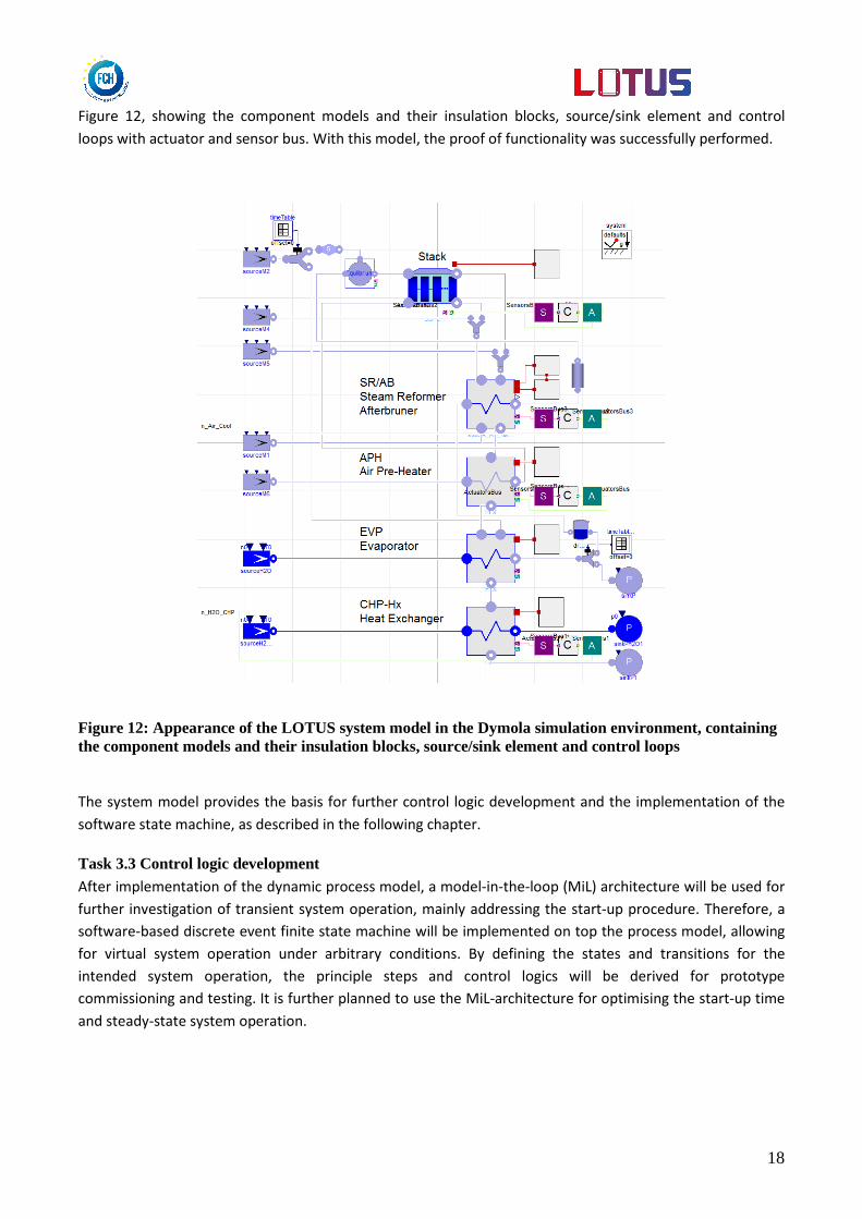
For the LOTUS system model, the updated system components are arranged together and control
mechanisms are introduced to enable automated system simulation for different operating modes. The
appearance in the Dymola environment is depicted in
18
Figure 12, showing the component models and their insulation blocks, source/sink element and control
loops with actuator and sensor bus. With this model, the proof of functionality was successfully performed.
Figure 12: Appearance of the LOTUS system model in the Dymola simulation environment, containing the component models and their insulation blocks, source/sink element and control loops
The system model provides the basis for further control logic development and the implementation of the
software state machine, as described in the following chapter.
Task 3.3 Control logic development After implementation of the dynamic process model, a model-in-the-loop (MiL) architecture will be used for
further investigation of transient system operation, mainly addressing the start-up procedure. Therefore, a
software-based discrete event finite state machine will be implemented on top the process model, allowing
for virtual system operation under arbitrary conditions. By defining the states and transitions for the
intended system operation, the principle steps and control logics will be derived for prototype
commissioning and testing. It is further planned to use the MiL-architecture for optimising the start-up time
and steady-state system operation.
19
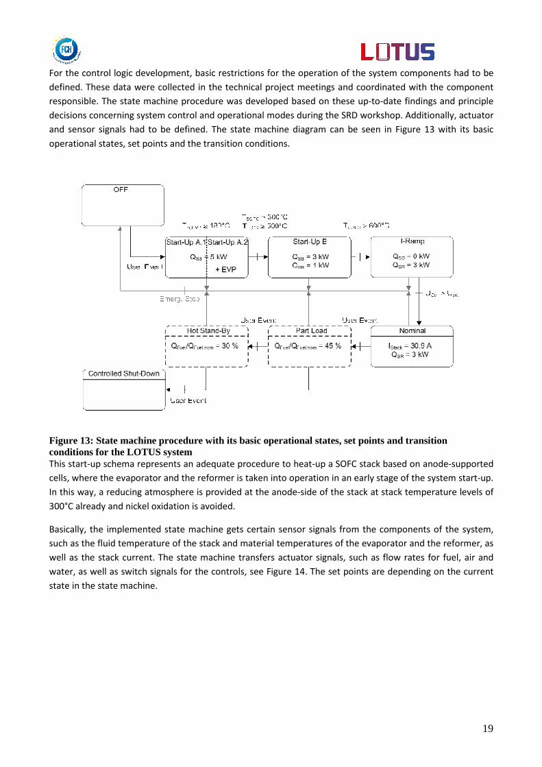
For the control logic development, basic restrictions for the operation of the system components had to be
defined. These data were collected in the technical project meetings and coordinated with the component
responsible. The state machine procedure was developed based on these up-to-date findings and principle
decisions concerning system control and operational modes during the SRD workshop. Additionally, actuator
and sensor signals had to be defined. The state machine diagram can be seen in Figure 13 with its basic
operational states, set points and the transition conditions.
Figure 13: State machine procedure with its basic operational states, set points and transition conditions for the LOTUS system This start-up schema represents an adequate procedure to heat-up a SOFC stack based on anode-supported
cells, where the evaporator and the reformer is taken into operation in an early stage of the system start-up.
In this way, a reducing atmosphere is provided at the anode-side of the stack at stack temperature levels of
300°C already and nickel oxidation is avoided.
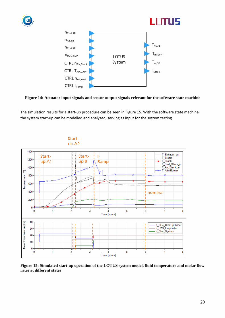
Basically, the implemented state machine gets certain sensor signals from the components of the system,
such as the fluid temperature of the stack and material temperatures of the evaporator and the reformer, as
well as the stack current. The state machine transfers actuator signals, such as flow rates for fuel, air and
water, as well as switch signals for the controls, see Figure 14. The set points are depending on the current
state in the state machine.
20
LOTUS
System
TStack
Tm,EVP
Tm,SR
IStack
nCH4,SB
nAir,SB
nCH4,SR
nH2O,EVP
CTRL nAir,Stack
CTRL TAir,CAPH
CTRL IRamp
CTRL nAir,cool
Figure 14: Actuator input signals and sensor output signals relevant for the software state machine
The simulation results for a start-up procedure can be seen in Figure 15. With the software state machine
the system start-up can be modelled and analysed, serving as input for the system testing.
Figure 15: Simulated start-up operation of the LOTUS system model, fluid temperature and molar flow rates at different states
21
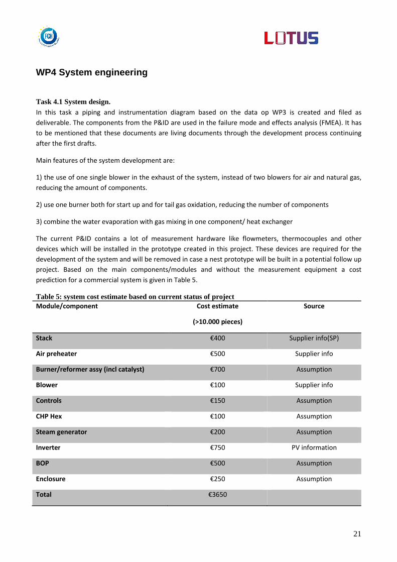
WP4 System engineering
Task 4.1 System design.
In this task a piping and instrumentation diagram based on the data op WP3 is created and filed as
deliverable. The components from the P&ID are used in the failure mode and effects analysis (FMEA). It has
to be mentioned that these documents are living documents through the development process continuing
after the first drafts.
Main features of the system development are:
1) the use of one single blower in the exhaust of the system, instead of two blowers for air and natural gas,
reducing the amount of components.
2) use one burner both for start up and for tail gas oxidation, reducing the number of components
3) combine the water evaporation with gas mixing in one component/ heat exchanger
The current P&ID contains a lot of measurement hardware like flowmeters, thermocouples and other
devices which will be installed in the prototype created in this project. These devices are required for the
development of the system and will be removed in case a nest prototype will be built in a potential follow up
project. Based on the main components/modules and without the measurement equipment a cost
prediction for a commercial system is given in Table 5.
Table 5: system cost estimate based on current status of project Module/component Cost estimate
(>10.000 pieces)
Source
Stack €400 Supplier info(SP)
Air preheater €500 Supplier info
Burner/reformer assy (incl catalyst) €700 Assumption
Blower €100 Supplier info
Controls €150 Assumption
CHP Hex €100 Assumption
Steam generator €200 Assumption
Inverter €750 PV information
BOP €500 Assumption
Enclosure €250 Assumption
Total €3650

22
Task 4.2: Development desulfurization
The technology chosen is ambient temperature, fixed bed adsorption, as this technology has the least impact
on the system and the materials which can be used are relatively inexpensive. After the determination of
the technology there are two major options:
- “Desulf 1”: materials sourced by HFCS - “Desulf 2”: desulfurization solution by third party
Each of the two technologies have their issues which can be brought back to an economical evaluation. The
“Desulf 1” solution uses inexpensive materials but the installation and treatment of the waste after use are
not well determined and economically evaluated. The “Desulf 2” uses somewhat more expensive materials,
but there is an agreement with a third party in place to install the desulfurization and deal with the waste
stream afterwards. The “Desulf 2” solution is chosen as the primary path forward to learn about this
technology and obtain economic data. Also this technology is being tested in other locations as well, which
creates a potential pathway for decreasing cost number by volume of systems. Based on miniflow data
measured in the lab an extrapolation of the requirements from the SRD (use of 2000 m3 NG/year, THT/
H2S/COS as Sulfur components) is used to determine the volume of the fixed bed desulfurization. The total
volume of the system would be 8 liters of materials.
Task 4.3: Development of heat exchangers In the LOTUS project there are 3 heat exchanger modules involved:
- Air preheater - CHP heat exchanger - Steam generator
The specifications of all three heat exchangers have been derived from the model created in WP 3 by IKTS.
The gas flows and temperatures from the model have been used to size the hardware. Special attention has
been paid to keep the pressure drop over the devices as low as possible, preferably below 10 mbar for each
device.
For each heat exchanger it is evaluated if it is possible to source the device from and existing company and
thus reducing the cost by having an off-the-shelf product, which is or has the capacity to be mass produced
in the future. Some of the components are very specific for the application and have to be developed in the
project The design is made keeping in mind is has to be mass manufactured at low cost in the future.
The air preheater has specific material requirements of being able to withstand a big temperature gradient
in the device from 20°C up to 650°C. This causes stresses in the device which calls for specific materials and
ways of construction. Various commercial suppliers have been contacted and a supplier is selected based on
technical and economical reasons. The device (Figure 16) is based on commercially available modular
building blocks which are combined to fulfil the LOTUS requirements. This offers a quick and economic
solution for the prototype. The supplier is capable and willing to customize future heat exchangers for our
specific needs to reduce costs. Obviously, this requires higher production volumes.
The CHP heat exchanger heats up the water for the house heating using the flue gas of the burner. The
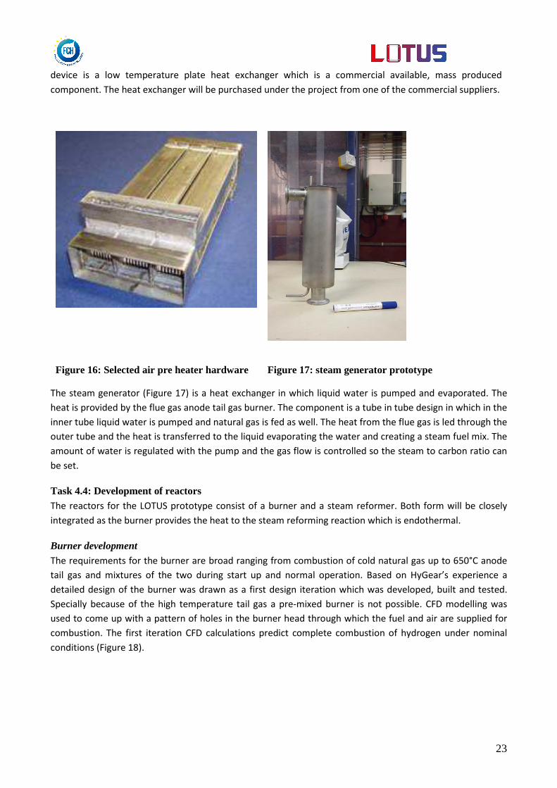
23
device is a low temperature plate heat exchanger which is a commercial available, mass produced
component. The heat exchanger will be purchased under the project from one of the commercial suppliers.
Figure 16: Selected air pre heater hardware Figure 17: steam generator prototype
The steam generator (Figure 17) is a heat exchanger in which liquid water is pumped and evaporated. The
heat is provided by the flue gas anode tail gas burner. The component is a tube in tube design in which in the
inner tube liquid water is pumped and natural gas is fed as well. The heat from the flue gas is led through the
outer tube and the heat is transferred to the liquid evaporating the water and creating a steam fuel mix. The
amount of water is regulated with the pump and the gas flow is controlled so the steam to carbon ratio can
be set.
Task 4.4: Development of reactors The reactors for the LOTUS prototype consist of a burner and a steam reformer. Both form will be closely
integrated as the burner provides the heat to the steam reforming reaction which is endothermal.
Burner development
The requirements for the burner are broad ranging from combustion of cold natural gas up to 650°C anode
tail gas and mixtures of the two during start up and normal operation. Based on HyGear’s experience a
detailed design of the burner was drawn as a first design iteration which was developed, built and tested.
Specially because of the high temperature tail gas a pre-mixed burner is not possible. CFD modelling was
used to come up with a pattern of holes in the burner head through which the fuel and air are supplied for
combustion. The first iteration CFD calculations predict complete combustion of hydrogen under nominal
conditions (Figure 18).

24
Figure 18: CFD model of nominal condition H2 combustion
The start up condition of the combustion of natural gas case showed a radial temperature profile which was
cooler at the wall of the burner (Figure 19). The methane destruction is predicted to be 99% complete.
Figure 19: CFD model of start up condition CH4 combustion
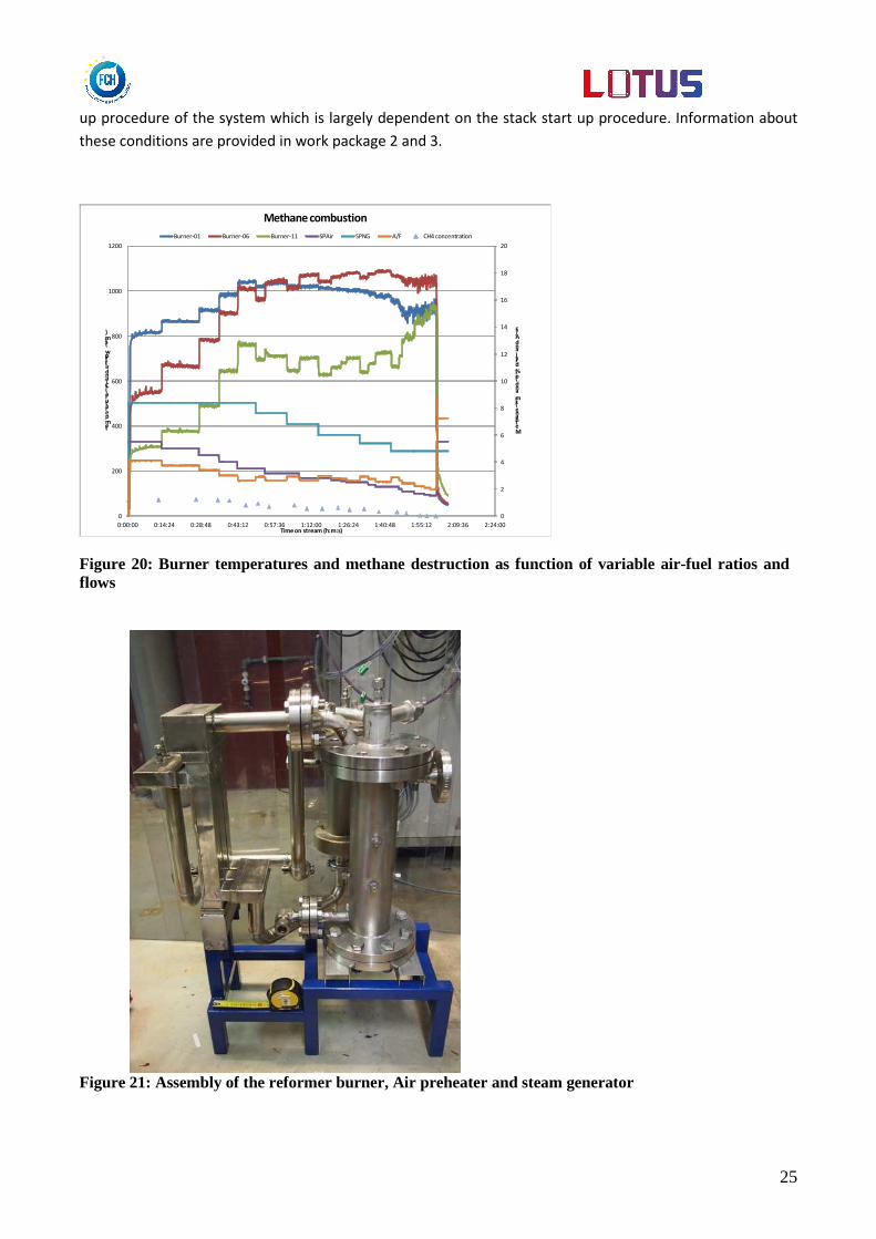
The first tests of the burner shows the combustion of both methane (Figure 20) and hydrogen at several
input conditions applicable to the LOTUS system. The next set of experiment will be determined by the start
25
up procedure of the system which is largely dependent on the stack start up procedure. Information about
these conditions are provided in work package 2 and 3.
0
2
4
6
8
10
12
14
16
18
20
0
200
400
600
800
1000
1200
0:00:00 0:14:24 0:28:48 0:43:12 0:57:36 1:12:00 1:26:24 1:40:48 1:55:12 2:09:36 2:24:00
Methane (slm and (ol% dry) and A/F
temperature (°C) and airflow (slm)
Time on stream (h:m:s)
Methane combustion
Burner-01 Burner-06 Burner-11 SPAir SPNG A/F CH4 concentration
Figure 20: Burner temperatures and methane destruction as function of variable air-fuel ratios and flows
Figure 21: Assembly of the reformer burner, Air preheater and steam generator

26
Steam methane reform catalysts from various suppliers have been tested under LOTUS process conditions in
a miniflow reactor at HyGear. Catalyst samples have been purchased and built in the test reactor with
thermocouples at inlet and outlet of the catalyst and at several places in the catalyst. The reactor was fed
with methane and steam by mass flow controllers. The catalyst was heated electrically by an oven controlled
at temperatures in the catalyst. The product gas was analyses by gas chromatography for H2, CO, CO2, CH4
and other potential species. The feed flows were derived from WP3 and where actually the same as the flow
which would be applied in the real system based on the 50% bypass of the reformer to allow partial internal
reforming. The best performing catalyst was chosen which also had the best economical outlook on pricing.
In this reactor the natural gas/ steam feed which has been mixed in the steam generator is heated to the
inlet temperature of the steam reform catalyst by heat transfer from the hot flue gas of the burner. This
heat transfer has been calculated and the appropriate heat exchanger has been designed and constructed.
The details of this system are described in D4.4. The reactor has been built and connected to the steam
generator and air pre-heater. The result ing hardware is shown in Figure 21. The big sized flanges are
needed to open the reactor when a failure occurs. The flanges are a big heat sink and influence the heat loss
negatively once not well insulated. In a subsequent design of the reformer they will be removed.
Task 4.5: Development of GAD system The development of GAD components is based on input from WP3 (task 3.2) and WP4 (task 4.1). In these
two WPs the estimations of required air and fuel flows and pressure losses were given. These figures were
not final but were sufficient to start development of GAD components. The final figures will be given after
measurements of first prototypes and then final optimization loop will follow if needed.
The design of GAD components is also influenced by complete system design. The main conceptual
difference between systems was in selection of pressurised system or under-pressurised system. Different
system concepts required different GAD architecture:
• Multiple blowers at inlet for air delivery and single blower at inlet for gas delivery
• Single blower at inlet for air delivery and single blower at inlet for gas delivery
• Single blower at outlet for GAD
Analytical simulations of all system architectures were performed. When considering the efficiency of
individual GAD components, the sealing issues, reliability and heat impact on life time of the most critical
GAD components the selection of single blower at outlet was selected.
The efficiency of the both prototypes is better than from the currently known blowers used in FC
applications. The work till now was mainly focused in definition of best system architecture and on
development and production of first samples. Another optimisation loop is expected which will be based on
requirements obtained already by measurements of the prototype components of the whole system.
Further work will be also made on development of the control logic to drive the motor.
27
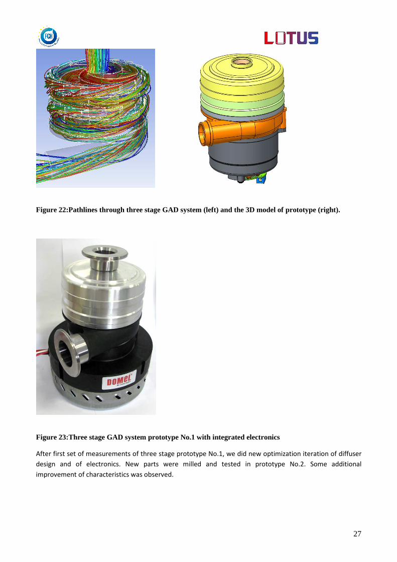
Figure 22:Pathlines through three stage GAD system (left) and the 3D model of prototype (right).
Figure 23:Three stage GAD system prototype No.1 with integrated electronics
After first set of measurements of three stage prototype No.1, we did new optimization iteration of diffuser
design and of electronics. New parts were milled and tested in prototype No.2. Some additional
improvement of characteristics was observed.
28
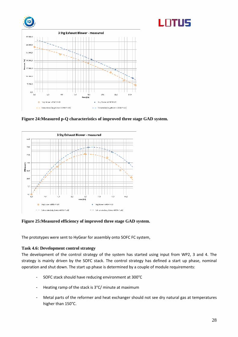
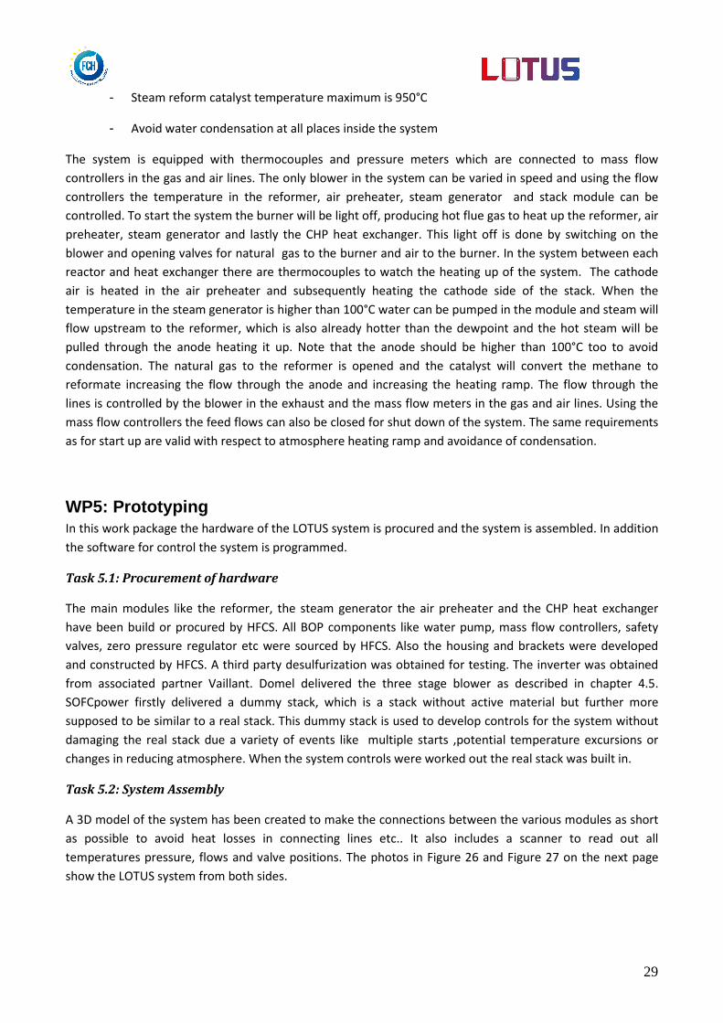
Figure 24:Measured p-Q characteristics of improved three stage GAD system.
Figure 25:Measured efficiency of improved three stage GAD system.
The prototypes were sent to HyGear for assembly onto SOFC FC system,
Task 4.6: Development control strategy The development of the control strategy of the system has started using input from WP2, 3 and 4. The
strategy is mainly driven by the SOFC stack. The control strategy has defined a start up phase, nominal
operation and shut down. The start up phase is determined by a couple of module requirements:
- SOFC stack should have reducing environment at 300°C
- Heating ramp of the stack is 3°C/ minute at maximum
- Metal parts of the reformer and heat exchanger should not see dry natural gas at temperatures
higher than 150°C.
29
- Steam reform catalyst temperature maximum is 950°C
- Avoid water condensation at all places inside the system
The system is equipped with thermocouples and pressure meters which are connected to mass flow
controllers in the gas and air lines. The only blower in the system can be varied in speed and using the flow
controllers the temperature in the reformer, air preheater, steam generator and stack module can be
controlled. To start the system the burner will be light off, producing hot flue gas to heat up the reformer, air
preheater, steam generator and lastly the CHP heat exchanger. This light off is done by switching on the
blower and opening valves for natural gas to the burner and air to the burner. In the system between each
reactor and heat exchanger there are thermocouples to watch the heating up of the system. The cathode
air is heated in the air preheater and subsequently heating the cathode side of the stack. When the
temperature in the steam generator is higher than 100°C water can be pumped in the module and steam will
flow upstream to the reformer, which is also already hotter than the dewpoint and the hot steam will be
pulled through the anode heating it up. Note that the anode should be higher than 100°C too to avoid
condensation. The natural gas to the reformer is opened and the catalyst will convert the methane to
reformate increasing the flow through the anode and increasing the heating ramp. The flow through the
lines is controlled by the blower in the exhaust and the mass flow meters in the gas and air lines. Using the
mass flow controllers the feed flows can also be closed for shut down of the system. The same requirements
as for start up are valid with respect to atmosphere heating ramp and avoidance of condensation.
WP5: Prototyping In this work package the hardware of the LOTUS system is procured and the system is assembled. In addition
the software for control the system is programmed.
Task 5.1: Procurement of hardware
The main modules like the reformer, the steam generator the air preheater and the CHP heat exchanger
have been build or procured by HFCS. All BOP components like water pump, mass flow controllers, safety
valves, zero pressure regulator etc were sourced by HFCS. Also the housing and brackets were developed
and constructed by HFCS. A third party desulfurization was obtained for testing. The inverter was obtained
from associated partner Vaillant. Domel delivered the three stage blower as described in chapter 4.5.
SOFCpower firstly delivered a dummy stack, which is a stack without active material but further more
supposed to be similar to a real stack. This dummy stack is used to develop controls for the system without
damaging the real stack due a variety of events like multiple starts ,potential temperature excursions or
changes in reducing atmosphere. When the system controls were worked out the real stack was built in.
Task 5.2: System Assembly
A 3D model of the system has been created to make the connections between the various modules as short
as possible to avoid heat losses in connecting lines etc.. It also includes a scanner to read out all
temperatures pressure, flows and valve positions. The photos in Figure 26 and Figure 27 on the next page
show the LOTUS system from both sides.

30
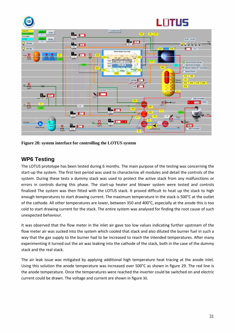
Task 5.3: build system controls
This task deals with both hardware of the control system and software programming. The hardware has two
purposes , besides the running of the system it also should be used for ensuring safety.
The control scheme of the system is shown in Figure 28. This screen shows all components, including
measurement devices like thermocouples , pressure measurements and flow meter.
The software used for the controls is HPVee (agilent).
Figure 26: LOTUS system; stackbox and inverter side
Figure 27: LOTUS system: reformer side, insulated
31
Figure 28: system interface for controlling the LOTUS system
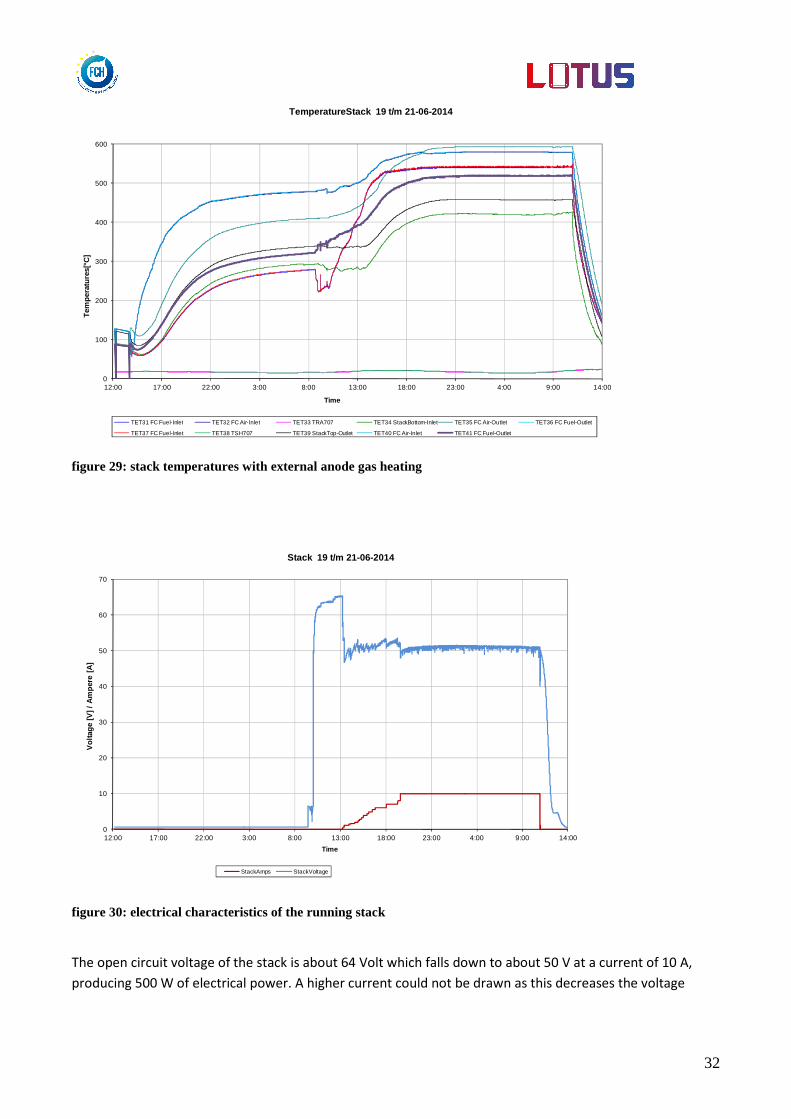
WP6 Testing
The LOTUS prototype has been tested during 6 months. The main purpose of the testing was concerning the
start-up the system. The first test period was used to characterize all modules and detail the controls of the
system. During these tests a dummy stack was used to protect the active stack from any malfunctions or
errors in controls during this phase. The start-up heater and blower system were tested and controls
finalized The system was then fitted with the LOTUS stack. It proved difficult to heat up the stack to high
enough temperatures to start drawing current. The maximum temperature in the stack is 500°C at the outlet
of the cathode. All other temperatures are lower, between 350 and 400°C, especially at the anode this is too
cold to start drawing current for the stack. The entire system was analysed for finding the root cause of such
unexpected behaviour.
It was observed that the flow meter in the inlet air gave too low values indicating further upstream of the
flow meter air was sucked into the system which cooled that stack and also diluted the burner fuel in such a
way that the gas supply to the burner had to be increased to reach the intended temperatures. After many
experimenting it turned out the air was leaking into the cathode of the stack, both in the case of the dummy
stack and the real stack.
The air leak issue was mitigated by applying additional high temperature heat tracing at the anode inlet.
Using this solution the anode temperature was increased over 500°C as shown in figure 29. The red line is
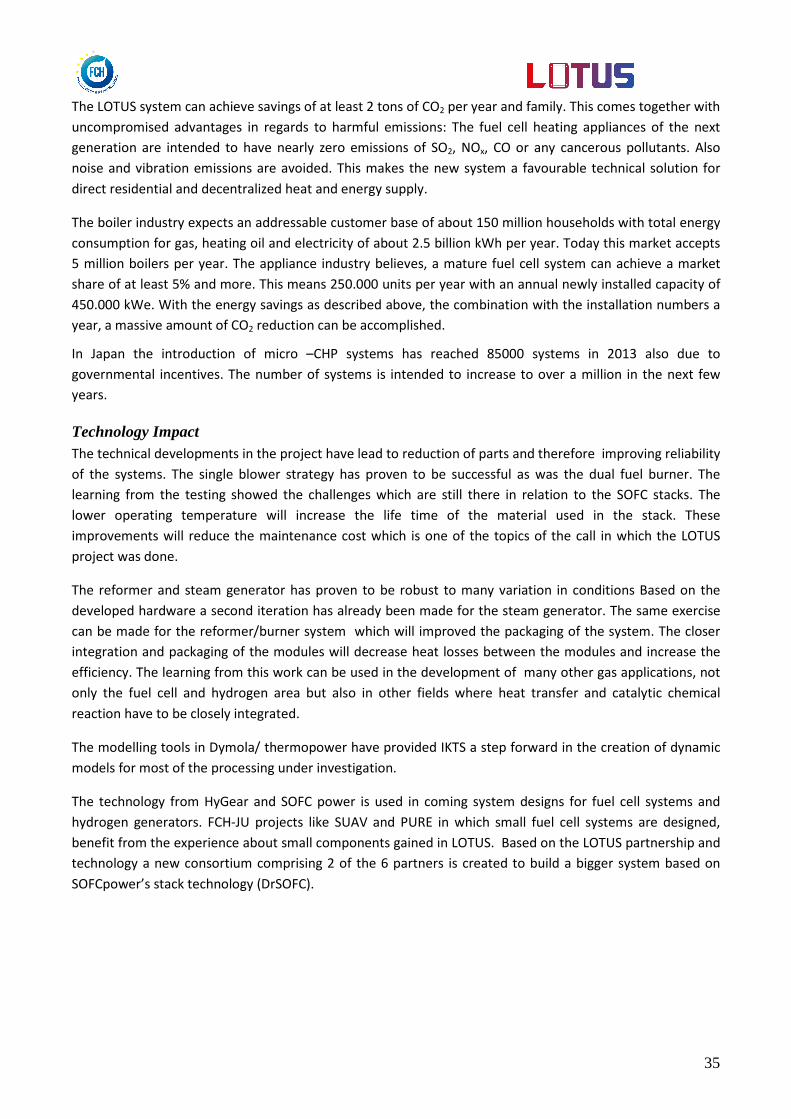
the anode temperature. Once the temperatures were reached the inverter could be switched on and electric
current could be drawn. The voltage and current are shown in figure 30.
32
0
100
200
300
400
500
600
12:00 17:00 22:00 3:00 8:00 13:00 18:00 23:00 4:00 9:00 14:00
Tem
pera
ture
s[°C
]
Time
TemperatureStack 19 t/m 21-06-2014
TET31 FC Fuel-Inlet TET32 FC Air-Inlet TET33 TRA707 TET34 StackBottom-Inlet TET35 FC Air-Outlet TET36 FC Fuel-Outlet
TET37 FC Fuel-Inlet TET38 TSH707 TET39 StackTop-Outlet TET40 FC Air-Inlet TET41 FC Fuel-Outlet
figure 29: stack temperatures with external anode gas heating
0
10
20
30
40
50
60
70
12:00 17:00 22:00 3:00 8:00 13:00 18:00 23:00 4:00 9:00 14:00
Vol
tage
[V] /
Am
pere
[A
]
Time
Stack 19 t/m 21-06-2014
StackAmps StackVoltage
figure 30: electrical characteristics of the running stack
The open circuit voltage of the stack is about 64 Volt which falls down to about 50 V at a current of 10 A,
producing 500 W of electrical power. A higher current could not be drawn as this decreases the voltage

33
below the inverter limit. To achieve a higher current and power production according to specificartions, a
higher stack temperature is needed. This was not possible in the system due to the air inleak problems.
0
100
200
300
400
500
600
700
9:30 14:30 19:30 0:30 5:30 10:30 15:30
Tem
pera
ture
s[°C
]
Time
TemperatureStack 23 t/m 24-06-2014
TET31 FC Fuel-Inlet TET32 FC Air-Inlet TET33 TRA707 TET34 StackBottom-Inlet TET35 FC Air-Outlet TET36 FC Fuel-Outlet
TET37 FC Fuel-Inlet TET38 TSH707 TET39 StackTop-Outlet TET40 FC Air-Inlet TET41 FC Fuel-Outlet
figure 31: stack operation with failure
In the next attempt to start up the system a stack failure occurred indicated by the quickly increasing
temperatures in figure 31. This sudden increase in the stack is caused by a cross leak of anode and cathode
gasses starting to burn in the stack. The system was immediately shut down for safety reasons. After this
failure, the stack was too much damaged to be operated and the system could not be tested further.
The total running time of the LOTUS system with the stack was limited due to problems to heat the stack and
the failure. All other hardware, reformer, steam generator, air pre-heater continue to work during the total
of about 1500 hours of testing. The blower of Domel was replaced once, which was expected. The first
blower was an early prototype of which the cover came loose during operation. In the second blower this
issue was fixed.
Unfortunately it was not possible to determine an efficiency number from the measured data. However, the
fuel processor has run for over 1500 hrs without issues. The single blower strategy worked well. Also the
burner was capable of both combusting natural gas as start up burner and as anode tail gas burner.

34
The potential impact (including the socio-economic impact and the wider societal implications of the project so far) and the main dissemination activities and exploitation of results The impact of LOTUS can be found in both marketing and also technology. The market of fuel cell powered
micro-CHP systems is growing. The technology developed by all partners can be used in future products
beyond micro-CHP systems.
Market Impact The use of distributed combined heat and power will greatly increase the energy efficiency compared with
conventional power plant and boilers as expressed in Figure 32. When the production and transportation of
the same amount of electricity and heat to a home by conventional means will take up to about 170 units,
producing those with a SOFC system at the point of use, only 100 units are needed. This will reduce the
energy consumption between 35 to 40% with accompanied similar CO2 emission reductions.
Figure 32: Diagrams showing the advantage of generating heat and power at the point of use. Note that efficiencies are only illustrative and will vary depending on the systems and countries involved (source Energy Environ. Sci., 2009, 2, 729–744)
Electricity
Heat
13
0
40
Electricity
Heat
10
0
7 losses
78 losses
40
units
45
units
15 losses
Po
we
r p
lan
t fu
el
Bo
ile
r fu
el
Power Plant with
Boiler
SOFC
system
35
The LOTUS system can achieve savings of at least 2 tons of CO2 per year and family. This comes together with
uncompromised advantages in regards to harmful emissions: The fuel cell heating appliances of the next
generation are intended to have nearly zero emissions of SO2, NOx, CO or any cancerous pollutants. Also
noise and vibration emissions are avoided. This makes the new system a favourable technical solution for
direct residential and decentralized heat and energy supply.
The boiler industry expects an addressable customer base of about 150 million households with total energy
consumption for gas, heating oil and electricity of about 2.5 billion kWh per year. Today this market accepts
5 million boilers per year. The appliance industry believes, a mature fuel cell system can achieve a market
share of at least 5% and more. This means 250.000 units per year with an annual newly installed capacity of
450.000 kWe. With the energy savings as described above, the combination with the installation numbers a
year, a massive amount of CO2 reduction can be accomplished.
In Japan the introduction of micro –CHP systems has reached 85000 systems in 2013 also due to
governmental incentives. The number of systems is intended to increase to over a million in the next few
years.
Technology Impact The technical developments in the project have lead to reduction of parts and therefore improving reliability
of the systems. The single blower strategy has proven to be successful as was the dual fuel burner. The
learning from the testing showed the challenges which are still there in relation to the SOFC stacks. The
lower operating temperature will increase the life time of the material used in the stack. These
improvements will reduce the maintenance cost which is one of the topics of the call in which the LOTUS
project was done.
The reformer and steam generator has proven to be robust to many variation in conditions Based on the
developed hardware a second iteration has already been made for the steam generator. The same exercise
can be made for the reformer/burner system which will improved the packaging of the system. The closer
integration and packaging of the modules will decrease heat losses between the modules and increase the
efficiency. The learning from this work can be used in the development of many other gas applications, not
only the fuel cell and hydrogen area but also in other fields where heat transfer and catalytic chemical
reaction have to be closely integrated.
The modelling tools in Dymola/ thermopower have provided IKTS a step forward in the creation of dynamic
models for most of the processing under investigation.
The technology from HyGear and SOFC power is used in coming system designs for fuel cell systems and
hydrogen generators. FCH-JU projects like SUAV and PURE in which small fuel cell systems are designed,
benefit from the experience about small components gained in LOTUS. Based on the LOTUS partnership and
technology a new consortium comprising 2 of the 6 partners is created to build a bigger system based on
SOFCpower’s stack technology (DrSOFC).
36
Dissemination activities All partners have participated in various activities to bring the LOTUS project under the attention of a
broader public. The main dissemination activities are :
Presentations at fuel cell conferences
• Publication of peer reviewed papers (see details below)
• Training of students on fuel cell test equipment
• The project web-site: www.lotus-project.eu
Some European heating appliance companies have shown interest in the technology of LOTUS and ways of
cooperation to bring the technology to the next level are being explored.
The development of intellectual property in the LOTUS project is limited as the technologies used are known
and the main objective of the project was to combine these technologies to make an efficient , reliable
system.

37