project management unit municipal service delivery program
TRANSCRIPT

Project Management Unit Municipal Service Delivery Program. Government of Khyber Pakhtunkhwa
Bidding Document
Improvement/Rehabilitation of Water Supply and Sanitation System in Dera Ismail Khan (DIK)
Improvement and Rehabilitation of 3 Nos. Tubewells at Fire brigade area
& Improvement and Rehabilitation of 6 Nos. Tubewells at Darya band area
including replacement of existing Water Supply main pipe
(Package # 1) Volume-II
March, 2020
Project Management Unit (MSP) Local Government, Election and Rural Development Government of Khyber Pakhtunkhwa
University Town Peshawar

Municipal Services Program
Improvement/Rehabilitation of Water Supply and Sanitation System in
Dera Ismail Khan (DIK)
Improvement and Rehabilitation of 3 Nos. Tubewells at Fire brigade area and
Improvement and Rehabilitation of 6 Nos. Tubewells at Darya band area including Water Supply Line
(Package # 1)
Tender Documents
Volume II
SPECIFICATIONS
TABLE OF CONTENTS
S.# DESCRIPTION Page No
Special Provisions
Section – 01 Special Provisions 1
Section – G 01 Contractor’s Camp 19
Section – G 02 Survey and Layout 20
Civil Works
Section –C 01 Clearing, Grubbing & Setting out of Works 22
Section – C 02 Excavations and Backfilling 24
Section – C 03 Plain and Reinforced Concrete 30
Section – C 04 Plastering and Rendering 72
Section – C 05 Dismantling Work 76
Section – C 06 Painting and Decorating 79
Section – C 07 Damp Proof Coarse 90
Section – C 08 Water proofing & Roof Treatment 92
Section – C 09 Miscellaneous Metal Works 95
SSection—C10 Brickworks 103

Municipal Services Program
Improvement/Rehabilitation of Water Supply and Sanitation System in
Dera Ismail Khan (DIK)
Improvement and Rehabilitation of 3 Nos. Tubewells at Fire brigade area and
Improvement and Rehabilitation of 6 Nos. Tubewells at Darya band area including Water Supply Line
(Package # 1)
Tender Documents
Volume II
SPECIFICATIONS
TABLE OF CONTENTS
S.# DESCRIPTION Page No
Electrical Works
Section – E 01 Basic Electrical Requirements 104
Section – E 02 Conduit System, Cable Tray, Cable Ladder and Trunking Installation 112
Section – E 03 Wire and Cable 119
Section – E 04 Mains & Sub-circuit Distribution 123
Section – E 05 Low Voltage Switchboards 127
Section – E 06 Luminaries and Accessories 142
Section – E 07 Wiring Devices 147
Section – E 08 Fire Alarm System 153
Section – E 09 Earthing System 157
Section – E 10 Lightning Protection System 164
Section – E 11 Testing, Commissioning, Inspections And Certifications 169
Section – E 12 Particular Specifications 178
Mechanical Works
Section – M 01 Mechanical Specifications 189
New Tube wells
Section – T 01 Tube well Specifications 196
Pipeline

Section – P 01 GI Pipes 196
Section – P02 HDPE Pipes

Volume-II
SECTION - 01
SPECIAL PROVISIONS

Volume-II
SECTION - 01
SPECIAL PROVISIONS
1.1 GENERAL
The General Conditions of Contract Part I & II shall form an integral part of these General Requirements.
The Contractor shall notify all sub-contractors of the provisions of the Conditions of Contract and the General Requirement of this Specification.
The arrangement and divisions of these Specifications is not to be construed as establishing the limits of responsibility of sub-trades.
The Contractor is responsible for delineating the scope of Sub-Contracts and for coordinating all the Works.
All works shall be carried out in accordance with the following specifications, supplemented by detailed specifications contained in the following sections. Any inconsistencies or ambiguities shall be brought to the notice of the Engineer for his clarification/decision. Decision and direction of the Engineer, in all such cases, shall be final and binding.
The Contractor shall make himself thoroughly familiar with the site conditions, foresee any and all problems likely to the encountered during execution of the works, and shall be able and ready to solve them effectively. Proposals for solutions to the problems shall be submitted to the Engineer for approval before proceeding with the work.
The Contractor shall make all necessary arrangements for community satisfaction regarding his operations related to the construction works.
1.2 APPLICABLE CODES AND STANDARDS
In the absence of other Standards being required by the Contract Documents, all work and materials shall meet the requirement of the Uniform Building Code of the United States, and/or applicable American Society for Testing Materials (ASTM) American Association of State Highway and Transportation Officials (AASHTO) Specifications and the latest American Concrete Institute Manual of Concrete Practice and American Institute of Steel Construction (AISC) Manual relevant to the Works except in cases where the Pakistan Building Code requires a higher standard. In such cases the Pakistani Code shall govern. Where the abbreviations listed below are used, it refers to the latest code, standards, or publication of the following organizations:
AASHTO American Association of State Highway and Transportation Officials ACI American Concrete Institute AISC American Institute of Steel Construction ANSI American National Standards Institute ASA American Standard Association ASCE American Society of Civil Engineers ASTM American Society for Testing and Material AWS American Welding Society BSI British Standards Institute ICAO International Civil Aviation Organization
SPECIAL PROVISIONS (1)

Volume-II
BSICP British Standard Institute Code of Practice PCA Portland Cement Association PSI Pakistan Standard Institute UBC Uniform Building Code
Should the Contractor, at any time and for any specific reasons, wish to deviate from the above standards or desires to use materials or equipment other than those provided for by the above standards, then he shall state the exact nature of the change giving the reasons for making the change and shall submit complete specifications of the materials and descriptions of the equipment for the Engineer's approval, whose decisions shall be conclusive and binding upon the Contractor.
1.3 CODES, STANDARDS, CERTIFICATES
The Contractor shall have at his site office:
Copies of all latest editions of codes and standards referred to in these specifications by number, or equivalent codes and standards approved by the Engineer.
Catalogues and published recommendations from manufacturers supplying products and materials for the project.
The Contractor shall provide manufacturer's or supplier's certificates to the Engineer for all products and materials which must meet the requirements of a specific code or standard as stated in these Specifications.
1.4 UNITS OF MEASUREMENTS
The SI System shall be used throughout this Project.
1.5 MANUFACTURER'S RECOMMENDATIONS
All material and products for any temporary and/or permanent work should be preferably locally manufactured /available in the local market and to be of best quality complying with the standards as specified herein. The Engineer may also supplement such specifications during the progress of work.
All materials and products used for such and other items shall be subject to standard testing and if found below the specified standard or their equivalent shall be removed from the site immediately at Contractor's own expense. All testing of materials finished and unfinished, shall be carried out by the Contractor at his cost, in the presence of the Engineer for which the Contractor shall maintain a reasonably well equipped laboratory of his own, close to the site of work or make any other additional arrangement to the satisfaction of the Engineer. The Contractor shall include testing charges in the rates and shall not be entitled to any reimbursement on this account for routine testing.
The Contractor must give early attention to the submission of samples of materials for approval of the Engineer, indicating the names of the manufacturing firms, where applicable, specially of cement, sand, aggregates, steel, water, tiles, hard-core and all finishes and fittings. Whenever practicable, samples shall be submitted at least three weeks before its proposed usage. Unless specified otherwise and whenever materials are ordered to be forwarded to a testing laboratory other than site laboratory for checking/ testing, the Contractor will be reimbursed the cost of fees for such tests if proved satisfactory, by the
SPECIAL PROVISIONS (2)
Volume-II
Employer. The Contractor, however, will be required to bear the cost of the fees for tests, which proved unsatisfactory.
Installation of manufactured items shall be in accordance with procedures recommended by the manufacturer or as approved by the Engineer.
1.6 EXISTING CONDITION AT SITE
Drawings and information pertaining to existing project conditions are furnished for reference.
Neither the Employer nor the Engineer warrants the adequacy or correctness of these.
1.7 PROTECTION AND PRECAUTIONS
The Contractor and his sub-contractors shall afford all necessary protection to existing structures and will be required to make good at his own expense any damage done to such structures through his own or his representatives or subcontractors' fault and negligence.
The Contractor and his sub-contractors shall afford all necessary protection to existing roads in the area. He will clear and make good at his own expense any damage to or debris on these roads through his own fault and negligence. He must at all time ensure the free and normal flow of traffic and shall not cause obstruction to the traffic system. The Contractor and his sub-contractors shall provide and maintain necessary protection and precautionary measures such as warning signs, warning lamps and barricades etc. to prevent accidents.
The Contractor shall promptly correct all such damage to original condition at no additional expense to the Employer. The Contractor shall cooperate with trades performing work under other Contracts as necessary for completion.
1.8 SETTING OUT OF WORK
Establish all boundaries, markers, levelling stakes and bench marks on the site to adequately set out all work. Verify all data and their relationship to establish Engineer's survey control points and public bench-marks and report discrepancies to the Engineer.
Permanently mark the necessary controls for distance and elevation sufficient to serve throughout the Contract and protect these control points adequately against damage and displacement.
Project setting out is for the use of all trades; each trade is responsible for the layout of its own work.
1.9 SEQUENCE OF CONSTRUCTION
The Contractor shall submit his proposal for approval of the Engineer the sequence of Construction, prior to starting the works. The works shall be executed as per approved sequence of construction.
The Contractor shall submit a complete plan of the proposed sequence and methods of operations for the execution of the works. Detailed drawings showing the location and
SPECIAL PROVISIONS (3)
Volume-II
construction of dumping and working platforms, gantries, building and all other structures in connection with the Contractor's plant and material storage sheds shall also be submitted to the Engineer for his approval.
The contract drawings are the working drawings to guide the Contractor generally about the shape and size of all the structures and fittings. Before proceeding to make preparations, fabrication, execution, erection of any such fittings and other details of any temporary works, scaffolds, railings, formworks; the Contractor shall be under obligation to prepare and submit detailed shop drawings to the satisfaction and the approval of the Engineer, before doing any or all of that described above or as directed. Approval of the contractor’s drawings shall not relieve the Contractor for any part of his obligation provided in the Contract Documents.
1.10 LINES AND LEVELS
Survey control points will be established by the Contractor and shall be checked by the Engineer. The Contractor shall be responsible for accuracy of these and shall be responsible for all requirements necessary for the execution of any work to the locations, lines, and levels specified or shown on the drawings, subject to such modifications as the Engineer may require as work progresses.
1.11 PARTIAL POSSESSION
Whenever, as determined by the Employer any portion of work performed by the Contractor is in a condition suitable for use, the Employer may take possession of or use such portion.
Such use by the Employer shall in no instance be construed as constituting final acceptance, and shall neither relieve the Contractor of any of his responsibilities under the Contract, nor acts a waiver by the Employer of any of the conditions thereof, provided that the Contractor shall not be liable for the cost of repairs, re-work, or renewals which may be required due to ordinary wear and tear resulting from such use. However, if such use increases the cost or delays to the completion of remaining portions of work, the Contractor will be entitled to an equitable adjustment.
If, as a result of the Contractor's failure to comply with the provision of the Contract, such use proves to be unsatisfactory, the Employer will have the right to continue such use until such portion of the work can, without injury to the Employer, be taken out of service for correction of defects, errors, omissions, or replacement of unsatisfactory materials or equipment, as necessary for such work to comply with the Contract; provided that the period of such operation or use pending completion of appropriate remedial action shall not exceed twelve months unless otherwise mutually agreed upon in writing between the parties.
1.12 EXISTING SERVICES
The Contractor shall search for, find, locate and protect any wiring, cable, duct, pipe work, etc., within or immediately adjoining the site area. The Contractor shall promptly inform the Engineer and Employer about the location and other details once any utility line is found.
The Contractor shall take full responsibly for safety of existing service lines, utilities and utility structures uncovered or encountered during excavation and construction operations.
SPECIAL PROVISIONS (4)
Volume-II
The Contractor shall take full responsibility for damaging any such service lines, utility/utility structure and any cost and/or expense that arises or issues from any such damage shall be borne directly by him. Should any damage to any such service occur, the Contractor shall forthwith take remedial action, initiate safety precautions, install temporary services and carryout repair all at his own cost and expense and inform the Engineer and notify all relevant authorities.
Existing utilities which are to remain in service for or after the works are to be determined by the Contractor. If any existing service lines, utilities and utility structures which are to remain in service are uncovered or encountered during these operations, they shall be safeguarded, protected from damage, and supported.
The contractor shall get approval from concerned authorities before working upon it and get approval or rerouting etc. The contractor shall demonstrate all safety requirements before carrying out work upon the electrical lines.
1.13 PLANT AND EQUIPMENT
The Contractor shall submit a detailed list of plant and equipment which he shall undertake to bring to the site to carry out the work. The list shall satisfy the Engineer as to type, size and quantity. The list shall include for each piece of equipment the type, manufacturer, model, identification number and year of manufacture. The Contractor shall provide on the site of the work at his cost all of the equipment listed and all subsequent equipment required for approval of the detailed programme of work and such equipment which may be directed by the Engineer. The Contractor shall supply all plant and equipment necessary for the construction of each phase of the work and it must be on site, inspected and approved by the Engineer.
1.14 CONSTRUCTION AREA AND ACCESS
The Contractor shall confine his operations to the areas that are actually required for the Works and shall fence the area accordingly. Arrangements for access roads, storage areas and routes for haulage of materials are to be made by the Contractor at his own cost, subject to the approval of the Engineer.
The contractor shall cordon off construction site and his storage area / site camp by providing and installation of GI sheet or any suitable material as approved by the Engineer. The contractor shall submit his plan in this regard and get approval of the Engineer before start of site cordon off.
1.15 STORAGE & HANDLING FACILITIES
The Employer will provide the Contractor possible space within or nearby the area of site of works for the storage of plant, equipment and materials and for Contractor's temporary office, during the currency of the Contract, Bidders are invited to visit the site, available area and access points to site. In case the adjacent area as required by the Contractor is not available within the Project boundary for storage of plant, equipment and machines then the Contractor shall arrange at his own expense possible space for storage of plant, equipment and machines at his own cost and expense. On no account shall such temporary installations conflict/interfere with any of the permanent installations, services and any operational
SPECIAL PROVISIONS (5)
Volume-II
function of Employer. The handling and storage of all plants, equipment and materials at site shall be the sole responsibility of the Contractor and at no risk and cost to the Employer.
The Contractor shall protect all material against corrosion, mechanical damage or deterioration during storage and erection on site. The protection methods shall be to the approval of the Engineer.
1.16 TEST LABORATORY AND TESTING
1.16.1 Testing, except as otherwise specified herein, shall be performed by an approved testing agency as proposed by the Contractor and approved by the Engineer and at no extra cost to the Employer. The Engineer may require all testing to be carried out under his supervision.
1.16.2 If suitable and adequate independent material testing laboratory is not available in the
vicinity, then the Contractor shall establish and maintain a materials testing laboratory at site within contractor’s camp and the laboratory shall have sufficient working area and shall be equipped with all necessary facilities including a suitable store/curing room. Contractor will provide seating arrangement for the Engineer’s Technician in the Lab. All acceptance testing shall be carried out under the Engineer’s Supervision. After completion of the Works, the contractor may demobilize material testing laboratory along with all equipment.
1.16.3 The Contractor shall supply and maintain to the satisfaction of the Engineer or his
representative complete testing equipment, apparatus, tools, gauges, instruments, etc. in sufficient number and adequate for all tests to be carried out as specified in these specifications. Valid calibration certificates of gauges / instruments / equipment shall be provided by the Contractor.
1.16.4 The Contractor, after the approval by the Engineer for the source of cement and steel shall
make available at the site sufficient stock of the materials in advance in order to allow sample testing for quality control prior to use.
1.16.5 The quality control testing shall be performed by the Contractor's competent personnel in
accordance with a site testing and quality control programme to be established by the Contractor and approved by the Engineer or his Representative. The Contractor shall keep a complete record of all quality tests performed on site and submit the same to the Engineer. All quality control and related tests shall be carried out in accordance with applicable standards and codes.
1.16.6 All costs associated with sampling, testing and inspection shall be borne by the contractor
which includes establishment of lab at site, staff hiring, test equipment, furnishing, office equipment, consumables, photo copies of relevant test standards, arrangement for calibration of equipment and transport for collection of samples from site/borrow areas/factory visits/witness of testing in independent approved labs.
1.17 CONSTRUCTION & CHECKING AT SITE
The Contractor shall submit to the Engineer in due time for approval and discussion, his proposals and plans as to the method and procedure to be adopted for the temporary and permanent works involved.
The submitting to these suggestions and arrangements, and the approval thereof by the Engineer shall not relieve the Contractor of his responsibilities and duties under the Contract.
SPECIAL PROVISIONS (6)

Volume-II
The carrying out of all work included in the Contract is to be supervised by a sufficient number of qualified representatives of the Contractor and full facilities and assistance are to be afforded by the Contractor for the Engineer or his Representative to check & examine the execution of the work.
The Engineer reserves the right to inspect all parts of the works but may at his discretion waive inspection on certain items. This shall in no way absolve the Contractor from his responsibilities. This particularly applies to the checking of materials, the accurate setting out of foundations, and to the levelling, setting and aligning of the various parts, and to the proper fitting and adjustment of manufactured and finished materials and fixtures in position.
If the Engineer or his Representative find that the work progress is slow in such a way that the works or parts thereof will not be completed in the time specified, then he shall order the Contractor to work overtime or in shifts and the Contractor shall comply. These arrangements will be free of all financial encumbrances and at no additional costs to the Employer.
In the event of night work, the Contractor shall provide sufficient and adequate lighting to the satisfaction of the Engineer or his Representative and shall supply the necessary manpower for satisfactory continuation of the work after normal hours. Also, the contractor shall arrange security and safety measures for his staff and Engineer’s staff upto the Engineer’s satisfaction before proposing night works.
1.18 BAR BENDING SCHEDULE
Bar bending (reinforcement bars) schedule of all drawings shall be prepared by the Contractor and submitted in triplicate to the Engineer for approval.
1.19 DRAWINGS
1.19.1 Tender Drawings: The drawings listed in the Tender documents, and these show the scope of work to be performed by the Contractor. Tender Drawings shall not be used as a basis for fabrication or construction but may be used as a basis for placing preliminary order for materials, subject to corrections based on the future issue of Drawings as provided under sub-clause 19.2 Drawings Issued for Construction. Tender Drawings are subject to be modified and supplemented by additional detail by the Engineer.
1.19.2 Drawings Issued for Construction: After Award of Contract, Tender Drawings shall be
placed by Drawings Issued for Construction including supplementary Specifications as may be necessary. Such drawings and specifications shall be constured to be included in the expression Custody of Drawings under Sub-Clause 6.1 of General Conditions of Contract. Drawings Issued for Construction may include some of the Tender Drawings with or without modification and additional drawings as required to express design intent in greater detail. Such drawings may also be modified from time to time. Drawings Issued for Construction will be the drawings from which shop, fabrication, erection, installation, concrete placing, formwork, or other construction detail drawings shall be prepared by the Contractor. The work shall be executed in conformity with Drawings Issued for Construction. The Contractor shall prepare a schedule of Drawings Issued for Construction of various parts of the Works based on Construction programme approved by the Engineer for issuance to the Contractor from time to time.
SPECIAL PROVISIONS (7)
Volume-II
1.19.3 Study of Drawings: The Contractor shall study all Drawings Issued for Construction carefully as soon as practicable after receipt thereof, and any errors discovered shall promptly be brought to the knowledge of the Engineer for his instructions.
19.4 Copies of Drawing: Drawings will be issued to the Contractor free of charge as follows:
Drawings Issued for Construction - One complete set in A-3 size as specified in sub-clause 6.1 Custody of Drawings, of General Conditions of Contract.
1.19.5 Drawings to be furnished by the Contractor:
(a) Shop Drawings.
All shop drawings required for the work including all kinds of fabrication, field erection, installation, placement and layout drawings shall be furnished by the Contractor for approval of the Engineer. If additional detail drawings are necessary to complete any part of the work, such including reinforcing steel, drawings shall be prepared by the Contractor and submitted to the Engineer for approval. All drawings shall be complete and shall be submitted in due time and in logical order to facilitate proper coordination.
(b) Lift and placement Drawings.
At least thirty calendar days prior to starting construction of any concrete lift or other placement, the Contractor shall submit lift or other placement drawings to the Engineer for approval. Lift or other placement drawings shall be submitted for each lift or other placement of concrete to be placed. These drawings shall be to such scale as to clearly show all recesses, openings, and embedded parts, including embedded structural steel, mechanical and electrical items, reinforcement placement in each lift in sufficient detail for proper execution of the work.
(c) Construction Plant Layout Drawings.
Three prints of drawings, showing the layout of construction plant and equipment the Contractor proposes to use on the work, shall be submitted by the Contractor for review to the Engineer. The drawings shall show the locations of the principal components of the construction plant, offices; storage areas and yards which the Contractor proposes to construct or use at the site of the work and elsewhere. The drawings shall also show the unloading facilities for materials and equipment at the work site.
1.19.6 Submissions and Approvals:
(a) Except as otherwise specified, three copies of each drawing for approval or review shall be
furnished to the Engineer. Within thirty calendar days after receipt, the Engineer will send one copy to the Contractor marked Approved, Approved/Except as Noted, or Returned for Correction. The notations Approved and Approved/Except as Noted will authorize the Contractor to proceed with the fabrication of the materials and equipment covered by such drawings subject to the corrections, if any, indicated thereon. Drawings returned for correction will be resubmitted for approval in the same manner as for new drawings. Every revision made during the life of the Contract shall be shown by number, date and subject in a revision block.
(b) Upon receipt of prints which have been Approved or Approved Except as Noted, the
Contractor shall furnish three prints plus one electronic copy in CAD of each drawing to the
SPECIAL PROVISIONS (8)

Volume-II
Engineer. If revisions are made after a drawing has been approved, the Contractor shall furnish 3 additional prints and electronic copy in CAD subsequent to each approved revision.
(c) Shop drawings to be prepared by a Sub-contractor shall be submitted in the same manner as
(a) & (b) above but they will be submitted through the Contractor.
(d) All of the applicable requirements of this Clause with reference to drawings to be prepared by the Contractor, including Sub-contractors, shall apply equally to catalogue cuts, illustrations, printed specifications, or other data submitted for approval.
(e) Any work done on Contractor's drawings shall be at the Contractor's risk. The Engineer will
have the right to request any additional details and to require the Contractor to make any changes in the drawings which are necessary to conform to the provisions and intent of design and specifications without additional cost to the Employer. The approval of the drawings by the Engineer shall not be construed as a complete check but will indicate only that the general method of construction and detailing is satisfactory. Approval by the Engineer of the Contractor’s drawings shall not be held to relieve the Contractor of his obligation to meet all the requirements of the Specifications or of his responsibility for the correctness of the Contractor's drawings or of his responsibility for correct fit of assembled parts in final position or of his responsibility for the adequacy of method of construction.
1.20 AS-BUILT DRAWINGS
The Contractor shall, at all times, keep on the site one copy of all drawings and approved samples together with copies of all building, mechanical, electrical and public safety codes and relevant standards applicable to the works. All such material shall be made available to the Engineer.
In addition, the Contractor shall, at all times, keep on site a separate set of prints on which shall be noted neatly, accurately and promptly as the work progresses all significant changes between the work shown on the drawings and that which is actually constructed. The sub-Contractors shall each keep on site, at all times, a separate set of prints of the drawings showing their parts of the work on which shall be noted, neatly accurately and promptly as work progresses the exact physical location and configuration of the works as actually installed, including any revisions or deviation from the Contract Documents.
At the completion of the works, the Contractor shall at his expense, supply to the Engineer six copies and CD containing electronic copy in approved version of CAD of all as built drawings amended to comply with the work "As Built". The Contractor shall provide in the same format as the original drawings, any additional drawing required to record the work.
1.21 RESTORATION AND CLEANING
The Contractor shall do regular cleaning and clean away all rubbish and excess materials that may accumulate from time to time on completion and before handing over. Upon completion of the works he shall obliterate all signs of temporary construction facilities such as work areas, structures, foundations of temporary structures, stock piles of excess or waste materials, or any other vestiges of construction, unless otherwise directed by the Engineer. The works and site shall be left in a clean and satisfactory state for immediate use and occupation. Care shall be taken not to use any cleaning materials which may cause damage to the surface to be cleaned.
SPECIAL PROVISIONS (9)

Volume-II
1.22 PROTECTION OF THE WORKS
In addition to the safety and security of equipment, materials and manpower on site, the Contractor shall whenever necessary cover up and protect the works from weather and damage by his own or other workmen performing subsequent operation. He shall provide all necessary dust sheets, barriers and guard rails and clear away the same at completion.
The Contractor shall take all proper steps for protection at all places on or about the works which may be dangerous to his workmen or any other person or to traffic. The Contractor shall provide and maintain warning signs, warning lamps and barricades as necessary.
1.23 PRODUCT DATA
Manufacture’s standard schematic drawings shall be modified or deleted to indicate only information which is applicable to the project. Such standard information shall be supplemented to provide all additional applicable information.
Manufacturer's catalogue sheets, brochures, diagrams, schedules, performance charts, illustrations and other standard descriptive literature shall be clearly marked to identify pertinent materials products or models. Dimensions and required clearances shall be indicated. Shop performance characteristics and capacities shall be noted.
1.24 SAMPLES
1.24.1 The Contractor shall furnish for approval of the Engineer/Consultant/Architect with
reasonable promptness all samples as directed by the Engineer or specifically called for in these Specifications. The Engineer shall check and such samples shall be approved by Architect/Consultant with reasonable promptness for compliance with the requirements of Contract Documents. All work shall be in accordance with approved samples. The approved sample shall be kept at site to verify each consignment.
1.24.2 Duplicate final approved samples, in addition to any required for the Contractor's use, shall
be furnished to the Engineer, one for office use and the other for the Site.
1.24.3 Samples shall be furnished so as not to delay fabrication, allowing the Engineer reasonable time for consideration of the sample submitted.
1.24.4 Each sample shall be properly labeled with the name and quality of the material,
manufacturer's name, name of the project, the Contractor's name and the date of submission, and the Specifications Article number to which the sample refers.
1.24.5 The manufacturer’s installation directions shall be provided with each sample. The
Contractor shall pay all transportation costs and deliver samples to the Engineer’s office, Site or testing laboratory as directed by the Engineer.
Samples will not be returned unless return is requested at the time of submission; all packing and transportation costs for the return of samples shall be paid by the Contractor.
1.24.6 Samples shall be of adequate size and number to permit proper evaluation of the material by
the Engineer. Where variations in colour, texture, dimensions or other characteristics are to be expected, the Contractor shall submit samples showing the maximum range of variation. Materials exceeding the range of variation of the approved samples shall not be used on the Work.
SPECIAL PROVISIONS (10)

Volume-II
1.24.7 If both Shop Drawings and samples are required for the same item, the Engineer may require both to be submitted before approving either.
1.24.8 No acceptance or approval of any Shop Drawings or sample, or any indication or directions
by the Engineer on any Shop Drawings shall constitute an authorization for any increase in the Contract Sum.
1.25 PRODUCT QUALITY AND HANDLING
Suppliers of local and foreign products and installations specified shall have been regularly engaged in the business of manufacturing, fabricating, installing and / or servicing work required for a period not less than 5 years. In addition, the Engineer may request as appropriate a:
- List of similar installations that describe project, scope and date of completion.
- Complete literature, performance data, and technical data.
- List of services record within Pakistan.
- Location of service office from which this installation could be maintained.
For the actual fabrication, installation and testing of the specified work, use only thoroughly trained and experienced workmen completely familiar with the items required and with the manufacturers recommended methods of installation. In acceptance or rejection, no allowance will be made for the lack of skill on the part of workmen.
Use all means necessary to protect materials before, during and after installation and to protect the installed work and materials of all other trades. In the event of damage, immediately make all repairs and replacement necessary for approval and at no additional cost to the Employer.
1.26 INSPECTION & TESTS REPORTS
The Contractor shall submit Quality Assurance Plan (QCP) in accordance with the Quality Assurance Plan (QAP) issued by the Engineer and carryout all testing and inspections works accordingly. All equipment and materials furnished under these specifications and all work performed in connection therewith will be subject to rigid inspection by the Engineer or the Engineer’s Representative. Acceptance of equipment and material or the waiving off inspection thereof shall in no way relieve the Contractor of his responsibility for meeting the requirements of the Contract.
The Contractor shall furnish the Engineer with certified true copies of test reports of all materials used in the manufacture and fabrication of all equipment and material including metal work, steel pipes, fire bricks etc. The result of these tests shall be in such form as to show compliance with the applicable Specifications, standards and codes for the material used.
SPECIAL PROVISIONS (11)
Volume-II
1.27 ACCIDENT PREVENTION, PROTECTIVE EQUIPMENT
The Contractor shall comply and enforce compliance by all his sub-Contractors with the highest standards of safety and accident prevention in accordance with international standards and in compliance with all applicable laws, ordinances and statutory provisions in Pakistan.
All requisite barriers, fences, warning signs, lights and other safety precautions as required for the protection of persons and property on or adjacent to the site shall be provided at the Contractor's cost.
All warning signs shall be in two languages, English and Urdu, and shall at all times be maintained in a clean and legible condition, to the satisfaction of the Engineer.
Trash shall be removed at frequent intervals to the satisfaction of the Engineer.
1.28 TEMPORARY FACILITIES
The Contractor shall provide, erect or install, maintain, alter as necessary and remove on completion except as otherwise directed by the Engineer all temporary facilities and services including access roads as described hereinafter and/or in the Contract Document.
Installation of temporary services at the site shall be given priority over all other construction at the site.
1.28.1 Temporary Road
The Contractor shall prepare and maintain such temporary roads as may be necessary, from the site to the nearest road and also within the site. Such roads shall be positioned strictly in accordance with the Engineer’s instructions and the Contractor shall reduce or control any dust nuisance by spraying with water as directed. The Contractor shall satisfy himself as to the locations and nature of the proposed access routes to the site and shall be responsible for preventing any damage whatsoever to adjacent property and vegetation and keeping the access road free from debris at all times.
1.28.2 Temporary Services
The Contractor shall provide all services at his own i.e water, power, sanitation, drainage whether required for his camp or construction works, the Employer may provide water and sewerage connections to the Contractor at agreed rates between Employer and Contractor.
1.28.3 Temporary Water Supply
The Contractor shall supply in sufficient quantity all necessary potable and other water for construction purposes for all trades at point within a reasonable distance of the work. He shall make arrangements and pay charges for water service installation, maintenance and removal thereof, and pay the costs of water for all trades.
When the permanent water supply and distribution system has been installed, it may be used as the source of water for construction purposes provided that the Contractor obtains the written approval of the Engineer and the Employer and assumes full responsibility for the entire water distribution system and pays all charges/costs for operation and maintenance of the system mutually agreed between the Employer and the Contractor.
SPECIAL PROVISIONS (12)

Volume-II
Temporary pipe lines and connections from the permanent service line, whether outside or within the area of site of works but necessary for the use of Contractor and his sub-contractor shall be installed, protected and maintained at the expense of the Contractor.
At completion of the work or at such time as the Contractor makes use of the permanent water supply installation, the temporary water services equipment and piping shall be removed by the Contractor at his own expense.
1.28.4 Temporary Electricity
The Contractor shall make all the necessary arrangements for a temporary electricity service, pay all expense in connection with the installation, operation and removal thereof and pay the costs of electricity consumed by all trades.
In the event that the site can not be connected to a local electricity network or where the available power is insufficient the Contractor has to make his own provision and maintain such installation.
A temporary lighting system shall be furnished, installed and maintained by the Contractor as required to satisfy the minimum requirements for safety and security. The temporary lighting system shall afford adequate general illumination to all building areas. Adequate outdoor lighting shall be provided to illuminate staging trenches and the like to the satisfaction of the Engineer and general illumination throughout adequate for watchmen and emergency personnel.
Temporary equipment and wiring for power and lighting shall be in accordance with the applicable provisions of governing codes. Temporary wiring shall be maintained in a safe manner and utilised so as not to constitute a hazard to persons or property.
When the permanent electrical power and lighting systems are in an operating condition, they may be used for temporary power and lighting for construction purposes provided that the Contractor obtains the written approval of the Engineer and the Employer and assumes full responsibility for the entire power and lighting system and pays all charges/costs for operation and maintenance of the system mutually agreed between the Employer and the Contractor.
Approval, license etc. if required under local laws will be obtained by the Contractor on his own responsibility and cost.
At completion of construction work, or at such time as the Contractor makes use of permanent electrical equipment and devices, temporary electricity services shall be removed by the Contractor as his own expense.
1.28.5 Waste Disposal
The Contractor shall make such temporary provisions as may be required in order to dispose of any chemicals, fuels, grease, bituminous materials, waste and soil waste and the like without causing pollution to either the site or the environment. Disposal of any materials, wastes, effluents, garbage, oil, grease, chemicals and the like shall be in areas specified by the concerned local authority proposed by the Contractor and subject to the approval of the Engineer. If any waste material is dumped in unauthorized areas the Contractor shall remove the material and restore the area to the condition of the adjacent undisturbed area. If necessary, contaminated ground shall be excavated, disposed off as directed by the Engineer
SPECIAL PROVISIONS (13)
Volume-II
and replaced with suitable fill material compacted and finished with topsoil all at the expense of the Contractor.
1.28.6 Fire Protection
The Contractor shall provide and maintain adequate fire protection in the form of barrels of water with buckets, fire bucket tanks, fire extinguishers, or other effective means ready for instant use, distributed around the project and in and about temporary inflammable structures during construction of the works.
Gasoline and other flammable liquids shall be stored in and dispensed from safety containers approved by the Engineer and storage shall not be within building.
Torch-cutting and welding operations performed by the Contractor shall have the approval of the Engineer before such work is started and a chemical extinguisher is to be available at the location where such work is in progress.
The Contractor shall follow the instructions and specifications of the Civil Defence Department and or other local authority.
1.28.7 Telephone
The Contractor shall immediately after receiving the Letter of Acceptance take the necessary steps to obtain a mobile and landline telephone on site. He shall be responsible for all installation and connection charges and periodic mobile and landline telephone accounts.
1.29 PROGRESS MEETINGS
The Contractor shall make all arrangements for progress weekly/monthly meetings including place, seating, presentation etc as approved by the Engineer. The meeting room must be air conditioned and sufficient for at least seating of twelve persons.
1.30 CONSTRUCTION SCHEDULE
A Construction schedule shall be maintained in accordance with the provisions of the General Conditions of Contract.
The schedule shall be accompanied with sufficient data and information including all necessary particulars of constructional plant, equipment machinery, temporary Works, arrival of plant, equipment at site and their installation, method of operation, work forces employed, etc., for activities of the Works.
Should the Engineer consider any alteration or addition in the programme and time schedule, the Contractor shall conform thereto without any cost to the Employer.
Whenever necessary and wherever the progress of the actual work shows departure, the programme and time schedule shall be undated and submitted to the Engineer for his approval.
1.31 NOTIFICATION TO THE ENGINEER
The Engineer’s Representative shall be notified daily in writing of the nature and location of the Works the Contractor intends to perform the next day so as to enable necessary inspection
SPECIAL PROVISIONS (14)
Volume-II
and measurement to be carried out. The Engineer may, if necessary, direct that longer notice be given of certain operations.
1.32 NIGHT WORK
For night work activities, the Contractor shall inform and submit his detail program/methodology and get prior approval from the Engineer. When work is done at night the Contractor shall maintain from sunset to sunrise such lights on or about his work and plant as the Engineer may deem necessary for the proper observations of the work and the efficient prosecution hereof.
1.33 WEATHER
No work is to be undertaken when, in the opinion of the Engineer, the weather is so unsuitable that proper protection of the work cannot be ensured.
1.34 CO-ORDINATION WITH OTHER CONTRACTORS
The Contractor shall make all necessary coordination with other Contractor (if any) and shall make sure that all embedding components such as pipes, steel bases etc. are properly, accurately and timely installed.
The Contractor shall inform the other contractor the schedule of any construction activity well in advance giving him sufficient time to finish his part of job, before any compaction/concreting etc. The Contractor shall get the signature of the authorized representation of the other contractor before carrying out any construction activity.
If any part of electrical work is damaged or has to be dismantled or redone due to negligence/omissions/incorrect position of the embedding etc. on part of the Contractor, all such losses/expensed shall be borne by the Contractor.
All expenses incurred for the above works including coordination are deemed to be covered in his tendered cost and no separate/extra payment shall be paid against such item.
1.35 SUBMISSION REQUIREMENTS
1.35.1 Schedule submission at least thirty days before the dates when reviewed submittals will
be needed.
1.35.2 Submit Shop Drawings as per provision given in Sub-Clause 19.5 (a) and number of copies of Product Data which the Contractor requires for distribution plus four copies which will be retained by the Engineer alongwith electronic copy in approved version of CAD.
1.35.3 Submit three samples unless otherwise specified.
1.35.4 Accompany submittals with transmittal letter, in duplicate, containing:
- Date
- Project title and number
- Contractor’s name and address
- The number of each Shop Drawing, Product Data and the Sample submitted.
SPECIAL PROVISIONS (15)

Volume-II
- Notification of deviations from Contract Documents.
- Other pertinent data.
1.36 RESUBMISSION REQUIREMENTS
Shop Drawings:
- Revise initial drawings as required and resubmit as specified for initial submittal. -
- Indicate on drawings any changes which have been made by the Engineer. - - Product Data and Samples: Submit new data and samples as required for
initial submittal.
1.37 SURVEY INSTRUMENTS
All the instruments, equipment, stakes and other material necessary to perform all work should be possessed by the Contractor. The survey work shall be carried out by competent staff consistent with the current practices. The Contractor shall maintain on site surveying instruments in perfect working conditions to enable the Engineer to check lines and level at all times.
Survey instruments and equipment shall include but not limit to the following:
- Electronic Total Station - Electronic Data Recorder - Disto Laser Meter - Precision Level Invert Staff - Automatic Levels - Power level - Compass, steel tape, ranging poles etc
1.38 WEEKLY PROGRESS REPORT AND PHTOGRAPHS
1.38.1 During the continuance of the Contract, the Contractor shall submit weekly progress reports on forms as approved by the Engineer. Such weekly reports shall show the actual progress completed as of date of the report plotted against the schedule as given by the Contractor at the start of work and shall be broken down so as to indicate status of all activities associated with mobilization design, material procurement, manufacture, surveys works, tests with regard to the agreed contract programme.
1.38.2 The Employer and the Engineer reserve the right to coordinate the schedules of this
Contractor and other Contractors working at the Site, and to adjust and/or change any and all such schedules as required during the course of construction in order to achieve a coordinated project in harmony with the Employer's completion date.
1.38.3 Commencing after the first week of construction, and continuing every week until
completion, the Contractor shall take and submit photographs to the Engineer's Representative, to show progress of his work and completion of each structure or major feature.
SPECIAL PROVISIONS (16)
Volume-II
1.39 CONTRACTOR TO NOTIFY DELAYS ETC.
Any delay which will affect the completion of Works shall be detailed by the Contractor who shall state the action he is taking for effective completion of the Contract programme.
The Contractor shall submit a report in respect of the various sections of the Works, the equipment in use or held in readiness, a return of labour and supervisory staff, and details of any matters arising which may generally affect the progress of the work.
The Contractor shall give a summary of the detailed progress report giving the position with regard to the agreed Contract programme.
The progress reports shall be set out in a format to the approval of the Engineer, and forwarded promptly so that on receipt the information contained therein is not more than 21 days out of date.
If during execution of the Contract, the Employer considers the progress position of any section of the work to be unsatisfactory, or for any other reason relating to the Contract, he will be at liberty to convene a meeting and the Contractor’s Representatives are to attend such meeting.
The Contractor's Site Office shall prepare and submit 6 copies of a weekly progress report to the Employer and Engineer's Site Office. This report shall summarize site activities, records and details where difficulties in maintaining the agreed program are being experienced or are likely to cause subsequent delay.
The Contractor's Site Office shall also prepare and submit to the Engineer's Site Office 2 copies of Daily Activity Report summarizing the main activities to be undertaken each day, noting special activities such a tests, alignment checks, etc. The Contractor shall be responsible for expediting the delivery of all material and equipment to be provided by him and his subcontractors.
1.40 PHOTOGRAPHS
As soon as work commences on Site, the Contractor shall provide the soft and hardcopies of the photographs (at least 10 to 12) of the works from positions to be selected by the Engineer. Each photographic print shall not be less than 297mm x 210mm and shall bear a printed description, a serial number and the date when taken.
The negatives/soft copy of all photographs shall be held at the Contractor’s Site Office, numbered and handed over to the Employer at the completion of the Contract. Soft copy of digital photos having description and serial number shall be submitted to the Engineer along with progress reports.
1.41 INAUGURATION PLAQUE
The Contractor at completion of the works shall construct an inauguration board as per size and details given by Employer/Engineer showing project details and inauguration date and the name of the inaugurating personality.
SPECIAL PROVISIONS (17)
Volume-II
1.42 SIGN BOARD
The Contractor shall construct/erect a Sign board as per size and details given by Employer/Engineer showing project details and names of the Employer, Granting Agency, Consultant and Contractor. The sign board shall be maintained by the Contractor for the entire construction duration.
1.43 FACILITIES FOR THE ENGINEER
1.43.1 Site Office
A single room Engineer’s office, 4 m. x 4.5 m., provided inside Contractor’s camp duly furnished deemed to be included in the Contract.
1.43.2 Transport
NOT REQUIRED
1.44 FACILITIES FOR THE EMPLOYER
NOT REQUIRED
1.45 PAYMENT OF WORK
No payment shall be made for the works involved within the scope of this section of specification.
The cost thereof shall be deemed to have been included in the quoted unit rate of other items of the Bills of Quantities.
In case of failure of the contractor to comply with all or any provision(s) of this clause the damage(s) caused shall be attributable towards the Contractor, and the Engineer shall assess the amount of such damage(s) which shall be deducted from the monies due or to become due to the Contractor. However, the said amount may be reimbursed to the Contractor on rectification of all damage caused and subsequent certification by the Engineer that the said damage has been rectified by the Contractor at his own cost as per the requirements specified herein above.
SPECIAL PROVISIONS (18)

Volume-II
SECTION - G 01
CONTRACTOR’S CAMP

Volume-II
SECTION G 01
CONTRACTOR'S CAMP
1. SCOPE
The work to be done under this item consists of construction, erection, installation and maintenance of the Contractor's Project Site Offices or main camp and the Contractor's sub-camps or temporary camps, if any, and shall include all offices, shops, warehouses, and other operational buildings; all housing and related facilities including accommodations for the Contractor's personnel.
2. GENERAL
The location of the Contractor's camps, including all buildings, utilities and facilities therefor, and of the camps or establishments of all persons/parties in the vicinity operating or associated with the Contractor shall be subject to approval of the Engineer.
The work to be done under this item will terminate upon the actual Completion Date. However, if directed by the Engineer or the Employer, the Contractor shall continue such work to the extent required by the Contractor's personnel during the period of maintenance. No compensation shall be paid for the continued operation and maintenance of the Contractor's Camps during the period of maintenance.
Upon completion of the Works, or at such time within the period of maintenance as directed by the Engineer, the Contractor shall remove all buildings utilities and other facilities from the Site and restore all camp areas to a neat and clean condition.
Contractor shall protect the environmental interests and HSE regulations at camp and works sites during execution of the contractual work.
3. CODES AND STANDARD
The construction, operation and maintenance of all camps of the Contractor shall comply with all applicable provisions of current Pakistan Labour Camp Rules.
4. MAINTENANCE
The Contractor shall furnish, make arrangements for, and carry out proper and adequate maintenance of the Contractor’s Camp areas at such camp to provide a neat, well-kept camp in all respects with pleasant and healthy surroundings and conditions for all occupants of their camp.
Adequately equipped and properly staffed portable first aid stations or dispensaries shall be provided by the Contractor at camps and other strategic locations to administer first aid treatment at any time required and free of charge to all persons on the Site, including employees of the Engineer and the Employer.
5. MEASUREMENT AND PAYMENT
No payment shall be made for the works involved within the scope of this section of specifications unless otherwise specifically stated in the Bill of Quantities or herein. The cost thereof shall be deemed to have been included in the quoted unit rate of other items of the Bill of Quantities.
CONTRACTOR’S CAMP (19)
Volume-II
SECTION – G 02
SURVEY AND LAYOUT
Volume-II
SECTION G 02
SURVEY AND LAYOUT
1. SCOPE
Under this item the Contractor shall make the stakeout survey for construction purposes with competently qualified men, consistent with the current practices. The work shall proceed immediately upon the award of the contract and shall be expeditiously progressed to completion in a manner and at a rate satisfactory to the Engineer. The Contractor shall keep the Engineer fully informed as to the progress of the stakeout survey. The scope of this section of specifications is covered by detailed specifications as laid down herein.
2. MATERIAL AND EQUIPMENT
All instruments, equipment, stakes and other material necessary to perform all work shall be provided by the Contractor. These instruments and equipment shall be available to Engineer at all times for the purpose of checking the work of the Contract.
All stakes used shall be of a type approved by the Engineer, clearly and permanently marked so as to be legible at all times. It shall be the Contractor's responsibility to maintain these stakes in their proper position and location at all times. Any existing stakes or markers defining property lines and survey monuments which may be disturbed during construction shall be properly tied into fixed reference point before being disturbed and accurately reset in their proper position upon completion of the work.
3. CONSTRUCTION
The Contractor shall trim trees, bushes and other interfering objects, not consistent with the plan, from survey lines in advance of all survey work to permit accurate and unimpeded work by his stake-out survey crews and the Engineer's survey crews. The exact position of all work shall be established from control points, which are shown on the plans or modified by the Engineer. Any error, apparent discrepancy in or absence of data shown or required for accurately accomplishing the stakeout survey shall be referred to the Engineer for interpretation or furnishing when such is observed or required.
The Contractor shall be responsible for the accuracy of his work and shall maintain all reference points, stakes, etc. throughout the life of the contract. Damaged, destroyed or inaccessible reference points, bench marks or stakes shall be replaced by the Contractor. Existing or new control points that will be or are destroyed during construction shall be re-established and all reference ties recorded thereon shall be furnished to the Engineer. All stakeout survey work shall be referenced to the centerlines shown on the Plans. All computations necessary to establish the exact position of the work from control points shall be made and preserved by the Contractor. All computations, survey notes and other records necessary to accomplish the work shall be kept neatly and made available to the Engineer upon request and furnished to the Employer upon Contract completion.
The Engineer may check all or any portion of the stakeout survey work or notes made by the Contractor and any necessary correction to the work shall be immediately made. Such checking by the Engineer shall not relieve the Contractor of any of his responsibilities for the accuracy or completeness of his work.
SURVEY AND LAYOUT (20)

Volume-II
Reference points, base lines, stakes and benchmarks for borrow pits shall be established by the Contractor.
All required right-of-way and easement limits shall be established, staked and referenced by the Contractor concurrent with the construction stakeout survey.
The Contractor shall place at least two offset stakes or references at each centre lines station and at such intermediate stations as the Engineer may direct. From computations and measurements made by the Contractor, these stakes shall be clearly marked with the correct centre line, station number, offset and cut or fill so as to permit the establishment of the true centre line location during construction. He shall locate and place all cut, fill, slope, line grade or other stakes and points as the Engineer may direct to be necessary for the proper progress of the work.
4. MEASUREMENT AND PAYMENT
No payment shall be made for the works involved within the scope of this section of specifications unless otherwise specifically stated in the Bill of Quantities or herein. The cost thereof shall be deemed to have been included in the quoted unit rate of other items of the Bill of Quantities.
SURVEY AND LAYOUT (21)

Volume-II
CIVIL WORKS
Volume-II
SECTION – C 01
CLEARING, GRUBBING & SETTING OUT OF WORKS

Volume-II SECTION C 01
CLEARING, GRUBBING & SETTING OUT OF WORKS
1.00 Clearing, Grubbing and Setting Out of Works
1.01 Scope of Work
The Work covered by this section of Specifications consists of furnishing all labour, materials, necessary equipment, services, miscellaneous and necessary items, required to satisfactorily complete the clearing, grubbing and setting out of the Works, as indicated on Drawings, specified herein and subject to the terms and conditions of the Contract.
1.02 Clearing
Clearing shall consist of cutting up or trimming of trees, if any, and the satisfactory disposal of trees and other vegetation designated for removal, together with the down timber, snags, bushes, and rubbish occurring within the areas to be cleared. Trees, other vegetation, stumps, roots, and bushes in areas to be clear shall be cut-off below the original ground to extract the roots except such individual trees, groups of trees and vegetation as may be indicated on the Drawings or designated by the Engineer to be left standing. Individual trees, groups of trees, and other vegetation, to be standing, shall be thoroughly protected from damage incident to construction operations by the erection of barriers or by such other means as the circumstances required, and as approved by the Engineer. Clearing operations shall be conducted so as not to cause any damage or harm to existing structures and installations and to those under construction, and so as to provide for the safety of employees and others.
1.03 Grubbing
Grubbing shall consist of the removal and disposal of all occurring stumps, roots larger than 38 mm in diameter, matted roots in the designated grubbing areas, stumps, roots, logs or other timber more than 38 mm in diameter, matted roots and other debris shall be excavated and removed to a depth not less than 450 mm below any subgrade, shoulder or slope. In areas where the cut is over 1.0m, grubbing shall not be necessary. In areas to be paved, or in areas indicated on the Drawings or designated by the Engineer as future paved areas where excess excavation from grading operations is placed, grubbing will be necessary.
1.04 Disposal
Unless directed otherwise, timber and other refuse shall be disposed off at locations approved by the Engineer in a manner that will avoid all hazards such as damage to existing structures, construction in progress, trees and vegetations. The Contractor shall be responsible for compliance with all pertinent laws and regulations pertaining to the burning of fires and observance of any security regulations applicable thereto.
Disposal by burning shall be kept under constant attendance until the fires have burned out or have been extinguished. No materials will be permitted to be pushed or placed on adjacent property without prior written approval of the owner of such property.
1.05 Setting Out of Works
The Contractor shall set out the Works and shall be responsible for true and perfect levels and setting out of the same and for correctness of the direction, positions, levels, dimensions and alignments of all parts thereof. If any error in this respect shall appear during the progress of
CLEARING, GRUBBING & SETTING OUT OF WORKS (22)
Volume-II the Work, the Contractor shall at his own expense rectify such error to the satisfaction of the Engineer. Any checking by the Engineer shall not relieve the Contractor from his complete unshared responsibility for correct setting out of Works. The Contractor shall construct and maintain accurate bench marks so that the lines and levels can be easily checked by the Engineer.
1.06 Drainage Ditches/Dewatering
The Contractor shall construct and maintain such ditches/drains in addition to those shown on Drawings or as may be ordered by the Engineer to adequately drain the areas under construction of the water from any source including subsoil water in foundations. If due to any negligence the area is flooded the same shall be drained with adequate measures by the Contractor at his own cost.
1.07 Method of Measurement and Payment
1.07.1 The quantities for clearing, grubbing & setting out of works including cutting,
removal and disposal of all materials shall be taken into account on the basis of Square meter and payment shall be made accordingly at the rate entered in the Bill of Quantities.
1.07.2 No separate payment shall be made for grubbing, clearing, disposal and protection
works and setting out of Works. The Contractor shall be deemed to cover the costs for this item of work in the unit price of other Contract items.
CLEARING, GRUBBING & SETTING OUT OF WORKS (23)

Volume-II
SECTION – C 02
EXCAVATION AND BACKFILLING
Volume-II
SECTION C 02
EXCAVATION AND BACKFILLING
2.00 Excavation and Backfilling
2.01 Scope of Work
The Work covered by this section of the Specifications consists of furnishing all plant, labour, equipment, appliances and materials and in performing all operations in connection with excavation, de-watering, filling, back-filling and disposal of all surplus and unsuitable material for construction works and foundations, complete in strict accordance with this section of the Specifications and the applicable Drawings and subject to the terms and conditions of the Contract and as per existing laws imposed by the local authorities.
The Contractor is to visit the site and ascertain for himself the condition of the surface of the ground and the type of soil likely to be encountered.
2.02 Original Levels
The quantity of excavation, earthwork, etc., shall be calculated from the level grid drawings to be produced by the Contractor and approved by the Engineer before commencement of any earthwork operation.
2.03 Setting Out
All setting out is to be checked and approved by the Engineer.
The Contractor shall take all necessary precautions during the progress of the Works to ensure that coordinated points are not disturbed and/or damaged.
If required, setting out is also to be checked and agreed with the local statutory body/authority.
2.04 Quality Control
2.04.1 Tests
Testing will be undertaken by an independent testing laboratory proposed by the Contractor or site lab established by the contractor and approved by the Engineer. All costs associated with sampling, transportation and testing shall be borne by the Contractor.
2.04.2 Standards
Relevant AASHTO Standards mentioned in Appendix-A of QC Plan will be used in sampling and testing of materials.
The Contractor shall have in effect at all times, a QA/QC program, which clearly establishes the authority and responsibility of those responsible for the quality system. Personnel performing quality functions shall have sufficient and well defined authority to enforce
EXCAVATION AND BACKFILLING (24)
Volume-II
quality requirements that includes but not limited to initiate, identify, recommend and provide solutions to quality problems and verify the effectiveness of the corrective action.
Implementation of the system shall be in accordance with the Contractor’s quality manual and project specific quality plan, which shall both, together with all related/ referenced procedures, be submitted to the Engineer for review, comment and approval.
The Engineer reserves the right to inspect materials and workmanship at all stages of construction and to witness any or all tests. The Contractor/Sub-Contractor, within 30 days after award, but prior to the pre inspection meeting, shall provide to the Engineer with a copy of his Construction and Inspection Plan for review, including any mandatory witness requirements of the Engineer.
2.05 Sub-Soil Conditions
2.05.1 The Contractor shall be deemed to have acquainted himself with the sub-soil
conditions on the Site and his bid shall be fully covering the works involved.
2.05.2 The Contractor shall make his own deductions for sub-surface conditions which may affect methods or cost of constructions of the work hereunder and he shall make no claim whatsoever for damages or compensation, should he find conditions during the progress of the Work, different from those as calculated and/or anticipated by him.
2.05.3 The Contractor shall be deemed to have made local and independent inquiries as
to the site conditions and shall take the whole risk of the nature of the ground, subsoil or material to be excavated or penetrated and the Contractor shall not be entitled to receive any extra or additional payment nor to be relieved from any of his obligations by reasons of the nature of such ground, subsoil or material.
2.05.5 It is envisaged that contractor may encounter foundations of dismantled structures.
Contractor should make his investigation and include efforts and cost required to dismantle, clear and disposal such subsurface foundations in the rate of excavation.
2.06 Excavation
2.06.1 Excavation shall include the removal of all material of every name and nature. If
rock or concrete is encountered, it should be removed carefully and without excessive noise and vibration. Use of explosives shall not be permitted and no extra rates or any payment in such a case shall be made to the Contractor.
2.06.2 The Contractor shall give reasonable notice to commence any excavation and he
shall submit to the Engineer full details of his proposals. If the Engineer may require modifications to be made in the Contractor’s proposals, the Contractor shall give effect to such modifications but shall not be relieved of his responsibility with respect to such work.
2.06.3 For major excavations, the Contractor shall submit for the prior approval of the
Engineer full details and Drawings showing the proposed method and procedure for supporting and strutting, dewatering and maintenance of adjacent structures. The
EXCAVATION AND BACKFILLING (25)

Volume-II
design, provision, installation, erection, maintenance and removal of such temporary works shall be the responsibility of the Contractor and all costs in these respects shall be deemed to be included in the rates quoted by the Contractor.
2.06.4 The Contractor’s attention is drawn particularly to his obligations under relevant
Clause of the Conditions of Contract in respect of those works which are in close proximity to existing buildings/structures.
2.06.5 The excavation shall conform to the dimensions and elevations as indicated on the
Drawings or as directed by the Engineer. Foundations on made up ground shall have to be taken down to natural bottom soil as per Drawings, direction and approval of the Engineer.
2.06.6 Excavation shall extend to a sufficient distance from wall and footings to allow for
placing and removal of forms, installation of services and for inspection but the same shall not be paid separately and is deemed to be included in the unit rates of the Contractor.
2.06.7 In the event of any excavations being carried out deeper than required/specified
levels, the same shall be filled in by the Contractor at his own cost to the required levels with lean concrete 1:3:6 under the footings and foundation slabs as per the instructions of the Engineer.
2.06.8 In the event of any excavations being carried out wider than the required/ specified
dimensions, the same shall be filled in by the Contractor at his own cost to the required levels with properly compacted well graded sand free from any deleterious substance as per directions of the Engineer.
2.06.9 No excavation shall be back-filled nor any Permanent Work commenced until the
foundation has been inspected by the Engineer and his permission to proceed given.
2.06.10 In case, any excavation is carried out and the pits and trenches, are filled with accumulated sand or debris from blowing windstorm, dust-storms, moving sand dunes or by any other reasons thereof after the levels were checked by Engineer, then the excavation or leveling shall have to be carried out again in the same manner as before unless and until concreting is done in the foundation/trenches. No separate payment shall be made on any such accounts.
2.07 Shoring and Bracing
2.07.1 The Contractor shall provide at his own cost, where required, all shoring, bracing,
walls, supports etc. to the sides of the excavation to prevent sliding or any movement. Where found necessary, excavated sides shall be sloped as directed by the Engineer with no extra cost to the Employer.
2.07.2 Shoring including sheet piling, where required during excavation, shall be installed to
protect workmen and the banks, adjacent, structures, paving and utilities. The term shoring shall also be deemed to cover whatever methods the Contractor selects to adopt with prior approval of the Engineer, for upholding the sides of excavation against the side of public roadways and adjoining properties in existing hardcore or
EXCAVATION AND BACKFILLING (26)

Volume-II
any other material. The Contractor will be held responsible for upholding the sides of all excavations and no claim for additional excavation, concrete or other material will be considered in this respect and shall be deemed to be included in his rates.
2.08 Dewatering and Drainage
2.08.1 The Contractor shall control at his own cost all the grading in the vicinity of the
Site of Work in order to prevent any water from running into the excavated areas.
2.08.2 The Contractor shall, at his own cost, keep dry all pits and trenches during construction and all dewatering and pumping out whether due to ground water seepage or otherwise shall be included in the rates as quoted by the Contractor except otherwise provided in the Contract. The method employed in all cases shall be approved and agreed by the Engineer.
2.09 Protection of Utility Lines
When any existing utility lines whether to be retained or to be removed are encountered within the area of operations, the Contractor shall notify the Employer/Engineer, and shall not proceed until necessary measures are taken for protection or removal of the lines and instructions are obtained from the Engineer/Employer. This will be done at no extra cost to the Employer.
2.10 Fill and Backfill
2.10.1 After completion of foundations, footings, walls, slabs and other construction
below the elevation of the final grades and prior to backfilling, forms shall be removed and excavation shall be cleaned of trash and debris. No backfilling shall be done until the entire foundations and footings etc. have been cured, inspected, approved and measured by the Engineer. Backfill shall be placed in horizontal layers not more than 6” thick and shall have proper moisture content for the required degree of compaction. Each layer shall be compacted by mechanical tampers or by other suitable equipment approved by the Engineer. Backfill shall be brought to a suitable elevation above grade to provide for anticipated settlement and shrinkage thereof.
2.10.2 Where concrete slabs, floors and pavements are to be placed on the ground, any
loam, organic and other unsuitable materials shall be removed.
2.10.3 Filling shall consist of suitable approved material from site excavation or approved granular material from outside source, free from lumps, debris, rubbish, wood, organic or other unsuitable matter and capable of compaction by approved means to achieve desired density. Contractor will make separate stocks of suitable and unsuitable excavated materials determined by tests at site for use of suitable material in backfill.
2.10.4 Fill, where required to raise the sub-grade for concrete slabs, shall be clean
unadulterated earth, free from deleterious and organic substances and shall also be free from wood, stones and other debris. In case, sand shall be provided for filling, the same shall be clean and free from harmful substances.
EXCAVATION AND BACKFILLING (27)
Volume-II
2.10.5 All materials, when used in fill shall be compacted to required modified AASHTO
density by power roller, mechanical rammer, or other approved equipment, in layers not more than 6” thick. In sand filling, each layer shall be uniformly spread, saturated with water or dried and then compacted. The Contractor shall arrange at his own cost the testing of the filling.
2.10.6 Backfill shall not be placed against foundation walls etc. before 14 days and not
prior to the damp proofing /water proofing treatment as specified elsewhere in these documents. Backfills shall be brought up evenly on each side of structures as far as practicable. Heavy equipment for spreading and compacting backfill shall not be operated closer to the structures less than the distance equal to the height of the backfill above the top of footing.
2.10.7 The filling material shall be subject to the approval of the Engineer and shall
conform to AASHTO Soil Classification System.
2.10.8 Filling around pipes and cables shall be carried out carefully by placing fine material to cover the pipe or cable completely before the normal filling is placed.
2.11 Compaction
Fill and/or backfill within the building or wherever required within the premises shall be compacted by approved means to a required compaction i.e. percent of maximum dry density as mentioned below;
Plastic Soil Granular material or sand
Top of fill up to 30 cm (2-layers) 95% 100% 30 to 75 cm below (3-layers) 93% 98% Below 75 cm each layer 90% 95%
2.12 Rough Grading
2.12.1 Necessary rough grading shall be carried out by the Contractor to establish the
finish grade or construction requirements of the Site, grades not otherwise indicated shall be uniform levels or slopes between points on existing and finished grades. Abrupt changes in slopes shall be rounded. Additional fill required to complete rough grading shall be provided as directed by the Engineer.
2.12.2 Where paving’s or slabs are specified, all rough grading shall be done to the sub-
grade of the base course, removing all large stones and debris and shall be compacted uniformly to the correct lines and levels ready to receive the paving or slab. Refilling, where required shall be executed with suitable selected materials in layers not exceeding 6” in thickness and thoroughly compacted to the required density.
2.13 Bottom Elevations of Footings/Foundations
The elevations as noted in the Drawings are only approximate and must be adjusted in the
EXCAVATION AND BACKFILLING (28)

Volume-II
field with the approval of the Engineer depending on the soil conditions encountered. No concreting shall begin until the design soil bearing capacity is substantiated by visual inspection by the Engineer. Where suitable foundation material is found lower than the underside of footings as detailed, the space between the founding material and footing soffit shall be backfilled with well compacted gravel/soling. Where soling is provided below the foundations, it shall be well compacted and the interspaces shall be properly filled with lean concrete.
The Contractor in planning his work shall make arrangements and provision to construct the lowest level footing first.
2.14 Disposal of Surplus Earth and Rubbish
All surplus earth, unsuitable material and rubbish shall be disposed off the Site as directed by the Engineer. The term disposal shall include all operations of loading, unloading, stacking, spreading, re-handling, filling depressions, leveling and grading as per instructions of the Engineer to the locations permitted by the concerned authorities.
2.15 Measurement & Payment
Excavation and backfilling shall be measured per cubic meter on the assumption of vertically excavated walls required for the nominal concrete dimensions of the structural members of the foundation shown on the Drawings and paid for at the unit rates entered in the Bill of Quantities, including compaction, disposal of surplus earth, dewatering, bracing, shoring etc.
EXCAVATION AND BACKFILLING (29)

Volume-II
SECTION – C 03
PLAIN AND REINFORCED CONCRETE
Volume-II
SECTION C 03
PLAIN AND REINFORCED CONCRETE
3.00 Plain and Reinforced Concrete
3.01 Scope of Work
The Work covered by this section of the Specifications consists of furnishing all plant, labour, equipment, appliances and materials and in performing all operations in connection with plain and/or reinforced concrete work complete in strict accordance with this section of Specifications, applicable Drawings and subject to the terms and conditions of this Contract.
3.02 Referenced Documents
Concrete Works shall be performed in strict accordance with the Specifications, drawings and the stipulations of the latest editions of the standards. British Standard Institute (BSI), the American Concrete Institute (ACI), the specifications of the American Society for Testing and Materials (ASTM) as referenced to throughout the Section shall be applicable subject to the Engineer’s approval.
Latest editions of the following Pakistan, British, ACI and ASTM Standards are relevant to these specifications wherever applicable.
Pakistan Standards
P S 232 Portland Cement (ordinary & rapid hardening)
P S 243 Natural aggregates for concrete
P S 279 Abrasion of coarse aggregates by the use of Los Angeles machine.
P S 280 Determination of aggregates crushing value.
P S 281 Organic impurities in sand for concrete aggregates
P S 282 Material finer than No. 200 B.S. test sieve in aggregates.
P S 283 Soundness test for aggregates by the use of sodium sulphate or magnesium sulphate.
P S 284 Sampling aggregates for concrete.
P S 285 Sieve or screen analysis of fine and coarse aggregates.
P S 286 Description and classification of mineral aggregates.
P S 421 Sampling fresh concrete.
P S 422 Slump test for concrete.
P S 560 Making and curing concrete compression test specimen in the field.
PLAIN AND REINFORCED CONCRETE (30)
Volume-II
P S 612 Sulphate Resistant Portland cement type `A’ and sampling fresh concrete in the laboratory.
P S 716 Mixing and sampling fresh concrete in the laboratory.
P S 717 Compacting factor test for concrete.
P S 746 Definitions and terminology of cements.
P S 849 Making and curing concrete compression test cubes.
ASTM (American Society for Testing and Materials)
C 33 Concrete Aggregates.
C 40 Organic impurities in sand for concrete.
C 87 Effect of organic impurities in fine aggregates on strength of mortar.
C 88 Soundness of aggregates.
C 94 Ready mixed Concrete.
C 117 Material finer than No.200 (0.075mm) sieve.
C 123 Light weight pieces in aggregates.
C 125 Concrete and concrete aggregates.
C 127 Specific gravity and absorption of coarse aggregate.
C 128 Specific gravity and absorption of fine aggregate.
C 131 Resistance to abrasion of small size coarse aggregate.
C 136 Sieve or screen analysis of fine and coarse aggregate.
C 142 Clay lumps and friable particles in aggregates.
C 143 Slump of Portland Cement Concrete.
C 150 Portland Cement.
C 156 Water retention by concrete curing material.
C 171 Sheet material for curing concrete.
C 172 Fresh concrete sampling.
C 289 Potential reactivity of aggregate.
C 309 Liquid membrane forming compounds for curing concrete.
PLAIN AND REINFORCED CONCRETE (31)

Volume-II
C 332 Light weight aggregates for insulating concrete.
C 494 Chemical admixtures for concrete.
C 535 Resistance to abrasion of large size coarse aggregates.
C 685 Concrete made by volumetric batching and continuous mixing.
D 75Aggregate sampling.
D 1751 Preformed expansion joint filler for concrete paving and structural concrete.
D 1752 Preformed sponge rubber and cork expansion joint fillers for
concrete paving and structural concrete.
D 1850 Concrete joint sealer (cold application type).
E 11Wire cloth sleeves for testing purposes.
E 96 Water vapor transmission of materials in sheet form.
E 154 Materials for use as vapor barrier under concrete slabs.
E 337 Relative humidity by wet and dry bulk psycho-meter.
C 400 Requirements for water for use in mixing and curing concrete.
C 995 Standard Test Method for Time of Flow of Fiber
Reinforced Concrete Through Inverted Slump Cone,
C 1018 Standard Test Method for Flexural Toughness and First-Crack Strength of Fiber-Reinforced Concrete (Using Beam With Third-Point Loading)
C 1116 Standard Specification for Fiber-Reinforced Concrete and Shotcrete
C 1399 Test Method for Obtaining Average Residual-Strength of Fiber-
Reinforced Concrete
British Standards
B.S 12 Portland cement, ordinary and rapid hardening.
B.S 410 Test Sieves
B.S 812 Methods for the sampling and testing of mineral aggregates, sand fillers
B.S 882 Concrete aggregates from natural sources
B.S 1881 Methods of testing concrete.
B.S 3148 Tests for water for making concrete.
PLAIN AND REINFORCED CONCRETE (32)
Volume-II
B.S 4027 Sulphate-resisting Portland cement.
C.P 8110 Structural use of concrete.
ACI (American Concrete Institute)
117 Standard Specifications for tolerances for concrete construction and materials.
201.2 Guide to durable concrete.
211 Recommended practice for selecting proportions for normal and heavy
weight concrete.
214 Recommended practice for evaluation of strength test results of concrete.
301 Specifications for structural concrete for building.
304 Recommended practice for measuring, mixing, transporting and placing concrete.
305 Hot weather concreting.
308 Standard practice for curing concrete.
309 Recommended practice for consolidation of concrete.
318 Building code requirement for reinforced concrete.
347R Guide to Formwork for concrete.
3.03 General
3.03.1 Until and unless specified or directed otherwise by the Engineer, all materials
and workmanship shall be based on the latest versions of applicable ASTM Standards in force at the time of inviting tenders.
3.03.2 Any defective work in the opinion of the Engineer shall be removed and
reconstructed without undue delay to the approval of the Engineer and the Contractor shall bear all additional costs incurred.
3.03.3 Any previous checks by the Engineer shall not in any way relieve the
Contractor of his responsibility in respect of quality and accuracy of Work.
3.03.4 Full care shall be taken to install embedded items. Embedded items shall be inspected and checks for reinforcements and other materials and items shall be completed and approved before concrete is placed.
3.03.5 The Contractor shall get the bar bending schedules of reinforcement checked
and approved by the Engineer prior to the cutting of reinforcement.
3.03.6 The Contractor shall maintain an accurate record of ambient temperature of Site.
Ambient temperature shall be measured using mercury thermometers or
PLAIN AND REINFORCED CONCRETE (33)

Volume-II
other thermometers acceptable to the Engineer.
3.03.7 Throughout the concrete work, the Contractor shall employ full time on the Works suitable number of qualified and experienced Engineers whose sole duties shall be as follows;
Design of concrete mixes Quality control of concrete Supervision of mixing, transporting, placing, compacting, finishing,
curing and protecting concrete.
Supervision of sampling and testing.
Preparation and submission of test certificates and reports.
Completion and keeping of record.
Such other duties as the Engineer may direct.
3.03.8 All concrete work including reinforcement etc. shall be carried out in accordance with the applicable requirements of ACI/ASTM/BSS Standards and to the instructions of the Engineer.
3.04 Materials
3.04.1 Cement: Cement shall be fresh and of approved make & source. It shall be
one of the following as specified by the Engineer;
a) Ordinary Portland Cement (OPC) conforming to ASTM C-150, Type-1 or British Standard Specifications BS-12.
b) Sulfate Resistant Cement (SRC) conforming to ASTM C-150,
Type-V or BS-4027.
c) Low Alkali (OPC) or (SRC) can be specified, if aggregates (Fine or Coarse) intended to be used in concrete found reactive with alkalis in cement by petrography and mortar bar tests as per ASTM C-295, C-227 or C-1260.
d) Slag cement, where specified, will be a blended cement containing
50 - 60% ground granulated blast furnace slag (conforming to ASTM C989 or BS 6699) and 40 - 50% Ordinary Portland Cement (BS 12) fully conforming to Code requirements for fineness, chemical composition, strength, setting time, soundness, etc.
e) The supply of cement must be so programmed by the Contractor that
at no time the quantity of cement stock shall be less than that required for an average consumption of four weeks. Lorry or truck or other means of transportation for the conveyance of cement to the Site of Work shall be clean, dry, metal-lined and covered from top with water proof sheets, so that cement is sufficiently protected from any deterioration during transit.
f) Cement shall be delivered in sealed bags and be stored in moisture-
protected and well-ventilated sheds and each cement supply shall be stored separately.
g) The Contractor shall provide at his own cost on the Site all necessary
PLAIN AND REINFORCED CONCRETE (34)

Volume-II
sheds which shall be perfectly dry, waterproof and adequately protected against ingress of water for the storing of cement to be delivered to the Work, to ensure adequate supplies being available for the Work.
h) Cement, which is damp or contains lumps which cannot be broken
to original fineness by finger pressure will be condemned irrespective of age and must be removed from the Site.
i) If any time the Engineer considers that any batch of cement may
have deteriorated on Site during storage for any reason, he will direct that tests shall be made and the batch of cement on the Site which may be in question shall not be used until it has been shown by test to be of satisfactory quality at a laboratory approved or appointed by the Engineer. The Contractor shall bear all costs of such testing. The Contractor without delay shall remove any rejected cement from the Site. Cement reclaimed from cleaning bags or leaking containers shall not be used in the Works and immediately be removed from the Site.
j) Cement shall be consumed in the sequence of its arrival at Site
unless otherwise directed by the Engineer.
3.04.2 Aggregates
a) All fine and coarse aggregates to be used shall be supplied from approved sources, which shall not be changed without permission in writing from the Engineer. Aggregates shall conform to the requirements of ASTM C33.
b) Fine aggregates, shall consist of natural sand, manufactured sand or
a combination thereof. It shall be clean, free from dust / clay, organic matters, other deleterious substances and impurities.
c) Fine aggregates shall conform to the following grading requirements
as mentioned in ASTM C-33;
Sieve Number/Size Percentage passing
9.5 mm (3/8") 100 4.75 mm (No. 4) 95 - 100 2.36 mm (No. 8) 80 – 100 1.18 mm (No. 16) 50 – 85 0.6 mm (No. 30) 25 – 60 0.3 mm (No. 50) 10 – 30 0.15 mm (No. 100) 2–10
Fineness modulus of fine aggregate shall be maintained between 2.4 to 3.0. It shall not vary more than +/- 0.2 in at least four out of five consecutive tests from the moving average of last five tests.
d) Coarse aggregates shall be approved river gravel or hard crushed
stone from a source approved by the Engineer and shall be clean, inert, hard, non-porous and free from laminated particles, sand, dust,
PLAIN AND REINFORCED CONCRETE (35)
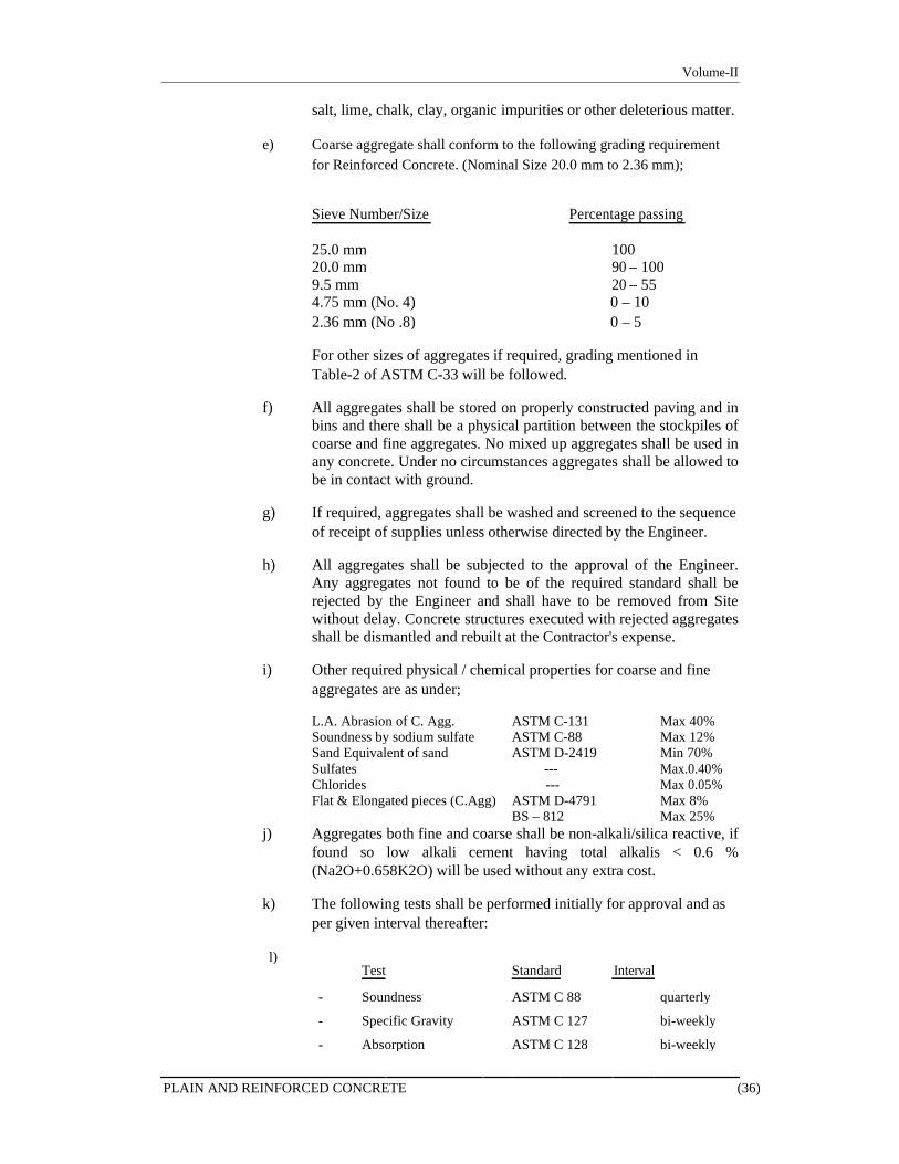
Volume-II
salt, lime, chalk, clay, organic impurities or other deleterious matter.
e) Coarse aggregate shall conform to the following grading requirement for Reinforced Concrete. (Nominal Size 20.0 mm to 2.36 mm);
Sieve Number/Size Percentage passing
25.0 mm 100 20.0 mm 90 – 100 9.5 mm 20 – 55 4.75 mm (No. 4) 0 – 10 2.36 mm (No .8) 0 – 5
For other sizes of aggregates if required, grading mentioned in Table-2 of ASTM C-33 will be followed.
f) All aggregates shall be stored on properly constructed paving and in
bins and there shall be a physical partition between the stockpiles of coarse and fine aggregates. No mixed up aggregates shall be used in any concrete. Under no circumstances aggregates shall be allowed to be in contact with ground.
g) If required, aggregates shall be washed and screened to the sequence
of receipt of supplies unless otherwise directed by the Engineer.
h) All aggregates shall be subjected to the approval of the Engineer. Any aggregates not found to be of the required standard shall be rejected by the Engineer and shall have to be removed from Site without delay. Concrete structures executed with rejected aggregates shall be dismantled and rebuilt at the Contractor's expense.
i) Other required physical / chemical properties for coarse and fine
aggregates are as under;
L.A. Abrasion of C. Agg. ASTM C-131 Max 40% Soundness by sodium sulfate ASTM C-88 Max 12% Sand Equivalent of sand ASTM D-2419 Min 70% Sulfates --- Max.0.40% Chlorides --- Max 0.05% Flat & Elongated pieces (C.Agg) ASTM D-4791 Max 8% BS – 812 Max 25%
j) Aggregates both fine and coarse shall be non-alkali/silica reactive, if found so low alkali cement having total alkalis < 0.6 % (Na2O+0.658K2O) will be used without any extra cost.
k) The following tests shall be performed initially for approval and as
per given interval thereafter:
l) Test
Standard Interval
- Soundness ASTM C 88 quarterly
- Specific Gravity ASTM C 127 bi-weekly
- Absorption ASTM C 128 bi-weekly
PLAIN AND REINFORCED CONCRETE (36)

Volume-II
- Abrasion ASTM C 131 quarterly
- Gradation ASTM C 136 daily
- Sand Equivalent ASTM D 2419 weekly
- Cleanliness ASTM C 227 weekly
- Flaky/Elongated ASTMD-4791 monthly
- Chloride --- quarterly
- Sulfates --- quarterly
Guidelines for adjustment in combined grading are given below.
Gradation of Combined Coarse and Fine Aggregates for Concrete
Particle Size Square Percentage by Weight Passing Sieves Openings (Equivalent Maximum Aggregate Size U.S. Sieve Designation) 50mm 37.5mm 25mm 19mm 9.5mm ----------------------------------------------------------------------------------------------------------------- ---- 63.00 mm (2 1/2 in.) 100 - - - -
50.00 mm (2 in.) 90- 100 100 - - -
37.05 mm (1 1/2 in.) 70– 90 90-100 100 - -
25.00 mm (1 in.) 50- 75 50 - 86 90 - 100 100 -
19.00 mm (3/4 in.) 45- 70 45 - 75 55 - 100 90 -100 -
12.05 mm (1/2 in.) - - - - 100
09.05 mm (3/8 in.) 38- 55 38 - 55 45-75 60-80 90-100
05.00 mm (No. 4) 30- 45 30 - 45 35 - 60 40-60 50-85
02.36 mm (No. 8) 22- 35 23 - 38 27 - 45 30-45 37-52
01.18 mm (No. 16) 15- 27 17 - 33 20 – 35 20-35 25-40
00.60 mm (No. 30) 10- 18 10 - 22 12 - 25 13 -23 15-25
00.30 mm (No. 50) 4- 10 4-10 5-15 5–15 5-15
00.15 mm (No. 100) 1 - 3 1 - 3 1 - 5 1 - 5 1 - 5
0.075 mm (No. 200) 0 - 2 0 - 2 0 - 2 0 - 2 0 - 2
3.04.3 Water
Water to be used in the Work shall be potable water and shall be free from all impurities whether suspended or dissolved. Further, the water shall not contain any chemical impurities, salts etc. of any kind. Water shall be tested for its fitness in Works in accordance with AASHTO Method T26-51.
PLAIN AND REINFORCED CONCRETE (37)
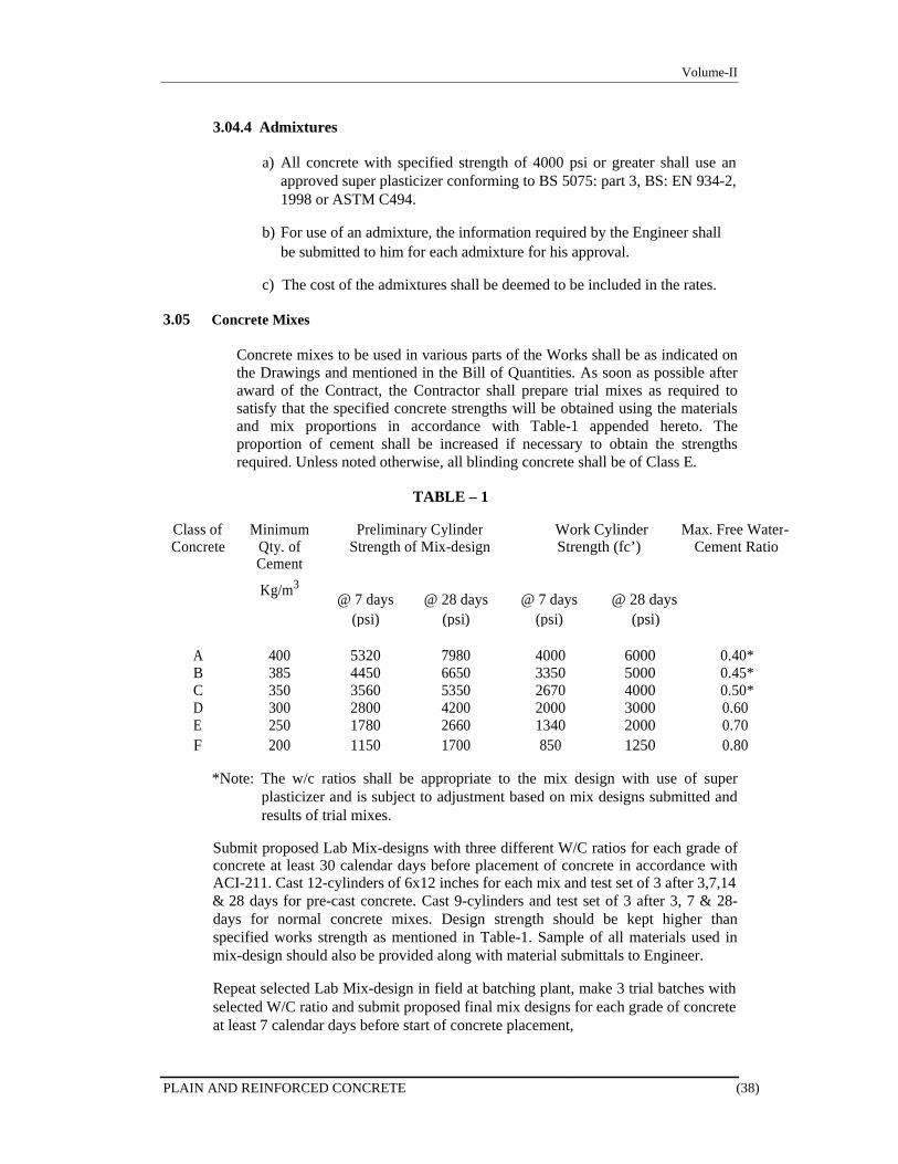
Volume-II
3.04.4 Admixtures
a) All concrete with specified strength of 4000 psi or greater shall use an
approved super plasticizer conforming to BS 5075: part 3, BS: EN 934-2, 1998 or ASTM C494.
b) For use of an admixture, the information required by the Engineer shall
be submitted to him for each admixture for his approval.
c) The cost of the admixtures shall be deemed to be included in the rates.
3.05 Concrete Mixes
Concrete mixes to be used in various parts of the Works shall be as indicated on the Drawings and mentioned in the Bill of Quantities. As soon as possible after award of the Contract, the Contractor shall prepare trial mixes as required to satisfy that the specified concrete strengths will be obtained using the materials and mix proportions in accordance with Table-1 appended hereto. The proportion of cement shall be increased if necessary to obtain the strengths required. Unless noted otherwise, all blinding concrete shall be of Class E.
TABLE – 1
Class of Minimum Preliminary Cylinder Work Cylinder Max. Free Water-
Concrete Qty. of Strength of Mix-design Strength (fc’) Cement Ratio
Cement
Kg/m3 @ 7 days @ 28 days @ 7 days @ 28 days
(psi) (psi) (psi) (psi)
A 400 5320 7980 4000 6000 0.40*
B 385 4450 6650 3350 5000 0.45*
C 350 3560 5350 2670 4000 0.50*
D 300 2800 4200 2000 3000 0.60
E 250 1780 2660 1340 2000 0.70
F 200 1150 1700 850 1250 0.80
*Note: The w/c ratios shall be appropriate to the mix design with use of super
plasticizer and is subject to adjustment based on mix designs submitted and results of trial mixes.
Submit proposed Lab Mix-designs with three different W/C ratios for each grade of concrete at least 30 calendar days before placement of concrete in accordance with ACI-211. Cast 12-cylinders of 6x12 inches for each mix and test set of 3 after 3,7,14 & 28 days for pre-cast concrete. Cast 9-cylinders and test set of 3 after 3, 7 & 28-days for normal concrete mixes. Design strength should be kept higher than specified works strength as mentioned in Table-1. Sample of all materials used in mix-design should also be provided along with material submittals to Engineer.
Repeat selected Lab Mix-design in field at batching plant, make 3 trial batches with selected W/C ratio and submit proposed final mix designs for each grade of concrete at least 7 calendar days before start of concrete placement,
PLAIN AND REINFORCED CONCRETE (38)
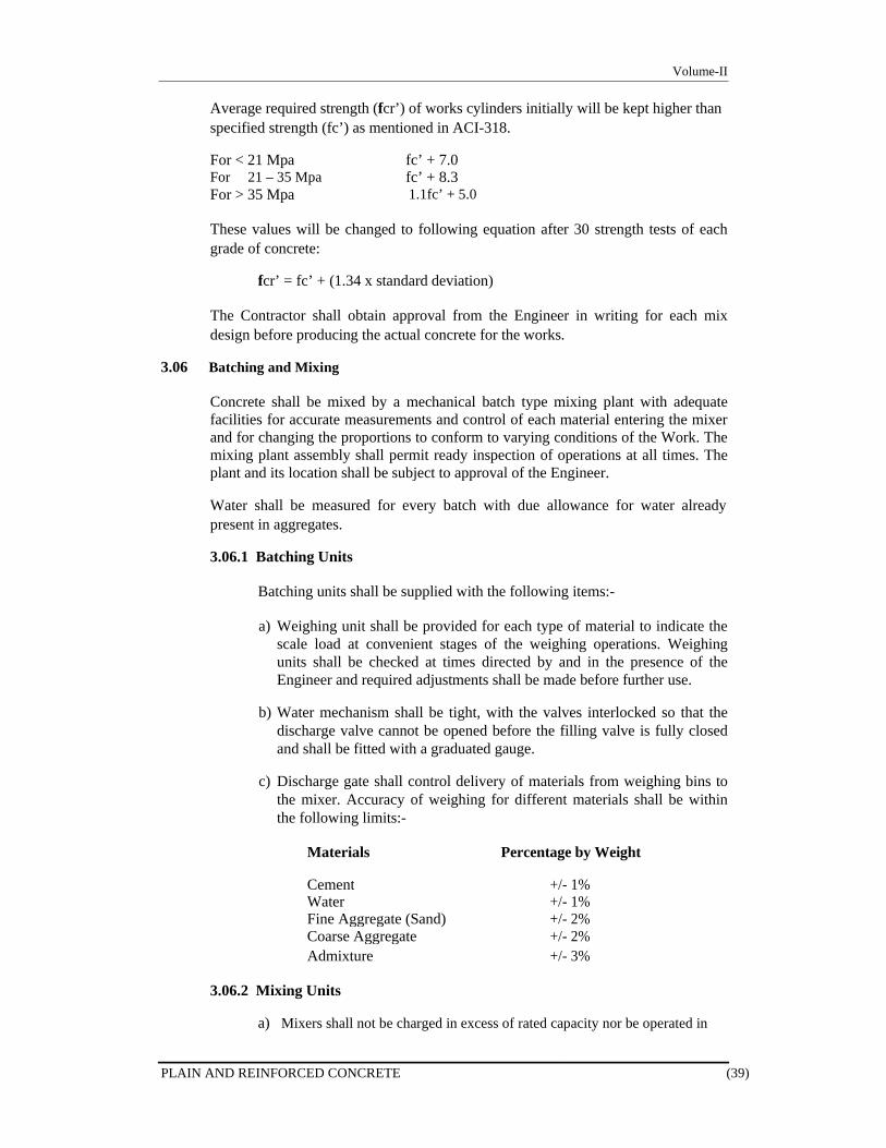
Volume-II
Average required strength (fcr’) of works cylinders initially will be kept higher than specified strength (fc’) as mentioned in ACI-318.
For < 21 Mpa For 21 – 35 Mpa For > 35 Mpa
fc’ + 7.0 fc’ + 8.3 1.1fc’ + 5.0
These values will be changed to following equation after 30 strength tests of each grade of concrete:
fcr’ = fc’ + (1.34 x standard deviation)
The Contractor shall obtain approval from the Engineer in writing for each mix design before producing the actual concrete for the works.
3.06 Batching and Mixing
Concrete shall be mixed by a mechanical batch type mixing plant with adequate facilities for accurate measurements and control of each material entering the mixer and for changing the proportions to conform to varying conditions of the Work. The mixing plant assembly shall permit ready inspection of operations at all times. The plant and its location shall be subject to approval of the Engineer.
Water shall be measured for every batch with due allowance for water already present in aggregates.
3.06.1 Batching Units
Batching units shall be supplied with the following items:-
a) Weighing unit shall be provided for each type of material to indicate the
scale load at convenient stages of the weighing operations. Weighing units shall be checked at times directed by and in the presence of the Engineer and required adjustments shall be made before further use.
b) Water mechanism shall be tight, with the valves interlocked so that the
discharge valve cannot be opened before the filling valve is fully closed and shall be fitted with a graduated gauge.
c) Discharge gate shall control delivery of materials from weighing bins to
the mixer. Accuracy of weighing for different materials shall be within the following limits:-
Materials Percentage by Weight
Cement +/- 1% Water +/- 1% Fine Aggregate (Sand) +/- 2% Coarse Aggregate +/- 2% Admixture +/- 3%
3.06.2 Mixing Units
a) Mixers shall not be charged in excess of rated capacity nor be operated in
PLAIN AND REINFORCED CONCRETE (39)

Volume-II
excess of rated speed. Excessive mixing requiring addition of water to preserve required consistency shall not be permitted. The entire batch shall be discharged and discarded before re-charging.
b) Mixing time shall be measured from the instant water is introduced into the
mixer drum containing all solids. All mixing water shall be introduced before one-fourth of the mixing time has elapsed. Mixing time for mixers of one cubic meter or less shall be not less than 2 minutes; for larger than one cubic meter capacity mixers, time shall be increased by 15 seconds for each additional half cubic meter or fraction thereof, which may be varied if the charging and mixing operations fail to result in the required uniformity in composition and consistence within a batch and from batch to batch. If an air-entraining agent is allowed to be used, additional mixing time shall be allowed so as to provide the specified air-content.
c) Unless waived by the Engineer, device such as discharge-lock to lock
the discharge mechanism, until the required mixing time has elapsed, shall be provided on each mixer. Mixing shall continue for at least 40 revolutions of mixer drum.
d) No hand mixing under any circumstances even with extra cement shall
be permitted. If during concreting, the mixing plant fails, the concrete already poured shall be removed, unless directed otherwise by the Engineer. Mixers, which have been out of use for more than 30 minutes shall be thoroughly cleaned before any further concrete is mixed.
e) The mixing water shall be regularly sampled and tested for salt content
and contamination.
3.07 Ready Mixed Concrete
Ready mixed concrete shall comply with the requirements of ASTM C94 and as agreed with the Engineer.
Each mixer truck shall arrive at the job Site with its water container full. In the event that a container is not full or concrete tests give a greater slump than acceptable, the load shall be rejected.
Shade temperature and concrete temperature shall be recorded at the point of discharge of the mixer and at placement for each load of concrete delivered to Site. Maximum and minimum temperature and wet bulb temperature shall be recorded daily.
Slump tests shall be performed in accordance with ASTM C143 or BS 1881 at the point of placement for each load delivered to the Site.
No water shall be added at the Site.
Transit mixers equipped with automated devices for recording the number of revolution of the drum shall be used.
The concrete shall be mixed and the water added to the mixer at the depot. No additional water shall be added at any stage from batching to placing.
PLAIN AND REINFORCED CONCRETE (40)
Volume-II
Truck mixer’s mixing performance when tested in accordance with BS 3963 shall be within the limits of table 5 of BS 1305.
The drum of the truck agitator or truck mixer shall be completely clean and empty before it is filled with concrete. Trucks shall not be loaded in excess of the manufacturer’s rated capacity, which shall be displayed on the vehicle in terms of the volume of mixed concrete.
Concrete shall be delivered, placed and consolidated within 45 minutes after the introduction of the water to the cement at batch plant when no admixtures are used, if admixtures are added at plant this time can be increased after check of setting time of concrete in field conditions and approval of engineer.
The concrete supplier may not introduce admixtures at either during transportation to the Site or at Site.
The actual batched weight of cement, water, admixture, additives and coarse and fine aggregates, the time of introduction of the water and the mixing temperature after water has been added shall be recorded on each delivery ticket by the supplier. When concrete is wet batched no water shall be added after batching.
In addition, where required by the Engineer, the Contractor shall provide details of the aggregate moisture contents determined at the plant. These shall be provided on a daily basis both as test results and in the form of a print out of the data programmed into the batching plant. The delivery ticket shall show details of any automatic adjustments to the quantity of water added to the mix, i.e. Compensating for the actual moisture contents measured during batching.
The supplier’s test certificate giving the results of tests on aggregates for workability and strength shall be submitted by the Contractor to the Engineer at weekly intervals.
Calibration of the Ready Mix Plant shall be carried out at regular intervals and calibration certificates of the plant shall be submitted to the Engineer.
3.08 Volume Batching
Volumetric batching may be allowed at contractor’s request in unavoidable circumstances with the Engineer’s approval after meeting following condition;
Trial mixes shall be prepared by volume also.
Contractor shall arrange standby concrete mixer in working condition.
Proper system of water and admixture dispensing will be adopted.
Batching and mixing will be supervised by Contractor’s QC Inspector.
Source & Grading of sand and aggregate shall be maintained as used in trial
mixes.
Materials shall be procured from approved sources only to avoid variation.
Cement shall be used from one source in one time. However, approval shall be obtained for more than one source in case of emergencies.
The Contractor shall follow inspection and testing plan as mentioned in QC plan.
Qualification tests shall be required for Engineer’s approval for all basic materials
PLAIN AND REINFORCED CONCRETE (41)
Volume-II
going to be used in permanent works i.e. cement, sand, coarse aggregate and steel etc.
3.09 Samples and Testing
3.09.1 General
Test cylinders of concrete shall be prepared and stored by the Contractor in accordance with the ASTM C-172, as and when directed by the Engineer. Test cylinders and the concrete materials shall be tested in an approved laboratory and the Contractor shall bear all charges for the same, including such other tests as may be determined by and acceptable to the Engineer.
3.09.2 Water
Water shall be tested in accordance with AASHTO Method of Test T26-51. Water for mixing in reinforced concrete shall be free from oil and shall not contain more than 1000 PPM chlorides and 1300 PPM sulphates (SO4). In Non-reinforced concrete water for mixing shall also be free from oil and shall not contain more than 2000 PPM chlorides and 1500 PPM sulphates (SO4) In no case shall the water contain an amount of impurities that will cause a change in the setting time of Portland cement by more than 25%, nor a reduction in compressive strength of mortar by more than 5% at the age of 14-days when compared with the results of same mix made with distilled water. Water for washing concrete aggregates shall be of the same quality as mixing. Water for curing concrete shall not contain impurities to cause discoloration or etching of surface. Quality of water shall be determined as per AASHTO T-26.
3.09.3 Cement
Cement shall be tested as prescribed in BS-12.
3.09.4 Aggregate
Aggregates shall be tested as prescribed in ASTM C-33. In addition, fine aggregates shall be tested for organic impurities in conformity with ASTM C-40.
3.09.5 Reinforcement
Reinforcement bars shall be tested as prescribed in BS 4449, BS-4461 and ASTM A-615 for deformed steel bars and mild steel plain bars. Refer clause 4.12 of this section for specification requirements of reinforcement works.
3.09.6 Testing of Concrete
3.09.6.1 Concrete Compressive Strength Test
a) Works Test Cylinders shall be made of all structural
concrete incorporated into the works. Unless otherwise
PLAIN AND REINFORCED CONCRETE (42)

Volume-II
directed by the Engineer, one set of cylinder of any particular mix shall be taken from either :- each pile concreted. each 350 cu.ft. or part thereof in columns
each 1000 cu.ft. in walls and small foundations each 1750 cu.ft. in slabs, beams and large foundations,or
each day's production whichever is the more frequent.
b) Each set of the Works Test Cylinders shall comprise six 6”x12” Cylinders made from a single sample of concrete taken from the point of final deposition of the set concrete under the Engineer's supervision.
c) The sampling, making, curing and testing of Works Test
Cylinders shall be carried out in accordance with ASTM C3 & C39. Test results shall be recorded on approved forms and submitted in duplicate to the Engineer immediately following the test.
d) A sample of concrete shall be taken at random on eight
separate occasions during each of the first five days of using that mix. The number of samples per day and the times which they are taken shall be varied at random (thereafter at least one sample shall be taken each day the concrete of that particular mix is made).
e) From each sample six Cylinders shall be made, three for
test at seven days, and three for test at twenty-eight days.
f) Specimens shall be cured under laboratory conditions except that the Engineer may require curing under field conditions in which case strength of field cured specimens shall not be less than 85% of that of companion laboratory condition cured specimens.
g) All cylinder moulds shall be steel moulds perfectly true,
having all internal and meeting faces machined to a smooth surface.
h) If the strength tests of the laboratory cured specimens for
any portion of the Work falls below the minimum allowable compressive strength at 28 days required for the class of concrete used in that portion, the Engineer shall have the right to order replacement of the affected work.
i) All test specimens shall bear distinguishing mark showing
number, date of casting, quality of concrete and place from where sample was taken. A proper daily record of test specimens made and test results obtained shall be maintained by the Contractor and weekly test results shall be submitted to the Engineer.
j) Statistical analysis for each grade of concrete shall be made
PLAIN AND REINFORCED CONCRETE (43)
Volume-II
for 30 test results as per ACI-214 and reported to the Engineer.
3.09.7 Concrete Members not complying with Specifications
(i) Where concrete in the Works does not comply with the Specifications, the Engineer may order any or all of the following or any other appropriate action to be taken:
(a) Drilling of cores from structure and testing its compressive
strength.
(b) To carry out load tests or other non-destructive tests on concrete structure.
(c) To cut out and replacement of such volume as is considered
defective by the Engineer.
(d) Strengthening of the structure in accordance with the requirements and as proposed by the Engineer.
(e) Any other action which in the opinion of the Engineer is
necessary.
(ii) The Contractor shall carry out all such tests, investigations, rehabilitation or replacement in coordination with and as acceptable to the Engineer at no additional cost to the Employer.
3.10 Transporting and Placing Concrete
3.10.1 General
a) Concreting shall be conveyed and deposited as quickly as possible
after mixing and shall proceed so that, as far as possible, a complete section of the Work is done in one operation. The concrete may be distributed in barrows, skips, and chutes and by any other method such as pumps, conveyor belts etc. all to the approval of the Engineer.
b) Transportation of concrete shall be in a manner approved by the
Engineer and shall be so as to avoid segregation or loss of ingredients of concrete.
c) All foundations and portions of Work to be concreted shall be
approved by the Engineer in writing before concrete is poured.
d) All forms and reinforcement shall be completed, cleaned, inspected and approved before pouring of concrete. No concrete is to be deposited till the Engineer has inspected and approved in writing all reinforcement, foundations, forms, details, positioning of all fixtures and materials to be embedded in concrete, control levels and screeds, etc. and is satisfied with the arrangements the Contractor has made to efficiently proceed with the work such as sufficient labour, materials,
PLAIN AND REINFORCED CONCRETE (44)
Volume-II
plants etc. Such an approval will not relieve the Contractor from any of his obligations under this Contract. No concrete shall be deposited without the written permission from the Engineer who shall have no authority to waive off this condition. Any concrete without such written authorization shall be liable to be rejected.
e) Placing of concrete shall not be permitted when, in the opinion of
the Engineer the sun, heat, wind, cold, snow, or limitations or facilities furnished by the Contractor prevent proper placing, finishing and curing of concrete.
f) All concrete shall be thoroughly compacted and consolidated by
means of pneumatic or mechanical immersion type vibrators of suitable size having minimum frequency of 8000 RPM. Care shall be taken to avoid segregation due to excessive vibration. The Contractor shall maintain on Site at all times one or more standby vibrators. Tapping or other external vibration of forms shall not be allowed unless so directed by the Engineer. In that case formwork shall be adequate to withstand vibrations. Compaction shall be done until the whole mass assumes a jelly like appearance and consistency with water just appearing on the surface. Concrete shall be sufficiently tamped and consolidated around the steel bars, care shall be taken that the vibrator does not touch steel or formwork, and is worked into all parts of the moulds in order that no voids or cavities are left. Steel shall not be disturbed during operations of concreting. Concrete shall be brought up in even layers of suitable thickness as per rate of placement for proper consolidation, to avoid cold joint and worked against side of forms to give a smooth and uniform surface. No surplus water shall be allowed to come out and lie on the surface of concrete. The concrete must be of such a consistency that when ramming, consolidating and tamping is completed, a thin film of water is just appearing on the surface. In vibrating, care shall be taken to avoid displacing the reinforcement.
g) Hardened concrete, debris and foreign materials shall be removed
from interior of forms and from inner surface of mixing and conveying equipment.
h) Runways and gangways shall be provided for wheeled concrete
handling equipment and workmen, and such equipment shall not be wheeled over reinforcement, nor shall runways be supported on reinforcement.
i) Concrete shall not be dropped freely from a height of more than 3.0
meters in columns and 1.2 meters elsewhere. In cases where an excessive drop is inevitable, the Contractor shall provide spouts, down pipes, chutes, or side ports to forms with pockets, which will let concrete stop and flow easily into the form without any risk of segregation. The discharge of the spouts, down pipes or chutes shall be controlled so that the concrete may be effectively compacted into horizontal layers.
j) Concrete is to be deposited as quickly as possible after mixing and to
proceed continuously. Concrete which has attained its initial set or
PLAIN AND REINFORCED CONCRETE (45)

Volume-II
has contained its mixing water for more than 45 minutes shall not be allowed to be placed in the work.
k) When concrete is laid on hard core, such as sub-grade for floor slabs, or
other absorbent material, the surface is to be watered, consolidated and, where specified, blinded before the concrete is deposited.
l) Fresh concrete shall not be placed on previously laid concrete or on
old concrete surfaces until the latter has been cleaned of all dirt, scum and laitance by wire brushes. The clean surface shall then be thoroughly wetted and grouted with cement slurry as approved by the Engineer.
m) Care shall be taken not to disturb newly placed concrete by vibrator,
indirect loading or otherwise. No traffic or loading shall be allowed on the concrete until it has thoroughly set and hardened.
n) Construction joints in concrete shall only be given at locations
indicated on the drawings or as approved by the Engineer. If approved by the Engineer, the concrete at the end of the day's work shall be finished off against a temporary shutter stop, which shall be vertical and securely fixed. Such stops shall be removed within 24 hours of placing of concrete. Construction joints not shown on the Drawings shall be reinforced with steel bars or dowels, if deemed necessary by the Engineer, and shall be furnished by the Contractor without any additional cost.
o) No concrete shall be placed during rains or inclement weather and
all fresh concrete shall be suitably protected from rain fall and excessive heat or cold.
p) Should any part of the exposed surface present a rough, uneven or
imperfect appearance, when the shuttering is removed, it shall be picked out to such depth and refilled and properly re-surfaced and entirely redone as per directions and approval of the Engineer at the cost of the Contractor.
q) On removal of the forms and before the concrete skin has had time to
harden, all faces of the concrete inside and outside to be kept exposed (i.e. un-plastered) shall be rubbed over with carborundum stone, and washed with cement to remove all marks, projections, hollows, or any other defect. No extra payment shall be made for this work.
r) All exposed surfaces and lines of the concrete work are to be true
and fair without cracks, bends, windings and distortions of all kinds, without any extra charges by the Contractor. All concrete work to remain exposed and un-plastered is to be fair-faced, smooth, pleasing and to the entire satisfaction of the Engineer.
s) A float or screed is to be worked over the exposed surfaces of all
concrete work on the flat or curve, so as to render the surfaces perfectly smooth, clear and to the necessary slopes or falls or as required to receive the floor or roof finishes according to the Drawings and as directed by the Engineer without any extra charge
PLAIN AND REINFORCED CONCRETE (46)

Volume-II
by the Contractor.
3.10.2 Temperature
No concrete shall be mixed or placed while the ambient temperature is above 35 degrees centigrade (°C) on a rising thermometer or above 40 degrees centigrade (°C) on a falling thermometer. The Contractor shall supply an accurate maximum and minimum thermometer and hang it in an approved position in the Works.
The Contractor shall plan the day’s concrete in such a manner as to ensure that each bay or panel is completed at a proper construction joint before the temperature rises above the permissible limit.
The Contractor shall allow in his rates for any additional expenses incurred by complying with this Clause in order to complete the works within the "Time for Completion".
Fresh Concrete temperature shall not exceed 32 degree centigrade in summer and shall not be less than 10 degree centigrade in winter.
3.10.3 Hot Weather Concreting
The following precautions should be adopted to maintain fresh concrete temperature ≤ 32 °C.
a) Shading of aggregate stock piles.
b) Insulation of water tanks and pipelines.
c) Use of chilled water.
d) Addition of ice flakes into mix to further lower temperature.
e) Shading of formwork and reinforcement from the sun and drying
winds.
f) Cooling of formwork and reinforcement by mist spraying prior to and ahead of casting of the concrete.
g) Covering and spraying with water of hardening concrete surfaces.
h) Concreting during the cooler part of the day.
Refer to ACI Standard 305R-99: Recommended Practice for Hot Weather Concreting.
3.11 Protection and Curing
3.11.1 General
All exposed concrete shall be cured. Curing shall be accomplished by preventing loss of moisture, rapid temperature change and mechanical injury or injury from rain or flowing water for a period of at least seven (7) days. Curing shall be started as soon as the concrete has hardened sufficiently for
PLAIN AND REINFORCED CONCRETE (47)

Volume-II
the surface not to be marked.
Curing shall be done either by covering with sand, hessian, canvas or other approved fabric mats, which shall be kept continuously wet. If required and so directed by the Engineer, formed surface with forms in position shall also be cured by keeping all forms continuously wet. As an alternative, curing of concrete on all exposed surfaces which could not be kept covered, such as sides of the beams, under side of the slabs, may also be done by sealing concrete surface with liquid membrane-forming curing compounds white pigment type conforming to ASTM C-309 or equal so as to arrest loss of moisture from concrete, with the approval of the Engineer. Care shall be taken so as to spray the compound/chemical on all the exposed faces of concrete so that no loss of moisture takes place. The Contractor shall take special care that curing of concrete is satisfactorily carried out and in accordance with methods specified herein and/or as instructed by the Engineer. Any negligence in this regard may result in total rejection of such concrete works, which in the opinion of the Engineer have not been adequately cured.
3.11.2 Curing Methods
a) Pounding
Build dike, then fill with water to cover the entire concrete slab. Avoid water or dike material that can stain the concrete. Use curing water at temperature within 20°F of the
concrete temperature. Avoid premature or sudden release of pounded water, which
can damage the surrounding environment.
b) Sprinkling or Fog Spraying Keep surface continuously wet. Alternate wetting and drying
may cause craze cracking. Use low water pressure and flow to avoid washing away the
fresh concrete surface. Use a water temperature within 20°F of the concrete temperature. Avoid if water runoff can damage the surrounding environment.
c) Using Wet Materials
Cover the concrete with wet hessian, straw, sawdust or sand. Wet continuously or cover plastic sheets and wet frequently. Avoid materials that discolor concrete. Prevent materials from blowing away.
d) Using Plastic Sheets or Waterproof Paper
Use flat type. Lap edges 6 inches and cover exposed concrete edges. Use minimum 4 mil thick plastic sheet; white in hot weather
and black in cold weather. Don't use on architectural concrete. Secure covering to prevent concrete exposure.
e) Using Curing Compounds
Apply white pigmented acrylic based curing compound conforming to ASTM C-309, Type-2 and approved by the engineer to the concrete
PLAIN AND REINFORCED CONCRETE (48)

Volume-II
surface as soon as the bleed water has dried and the fresh concrete has hardened sufficiently.
3.11.3 Thick Sections
a) For sections of 5 feet thick or more, proper arrangements shall be made to
control the temperature of the concrete during mixing and placing and to control the heat of hydration. The Contractor shall ensure that the maximum concrete temperature shall be limited to 70°C. For methods to pre-cool concrete, refer to Subsections 4.09.2 & 4.09.3.
b) To minimize the potential for thermal cracking, the maximum temperature
differential between the inner core and outer surfaces must not exceed 20°C. This temperature differential is the difference between the temperature at the hottest portion of the concrete and that at the surface. The Contractor shall submit to the Engineer his proposals to control and monitor this.
c) To minimize temperature differential, the top surface of the poured raft shall
be properly insulated to keep it warm and to decrease the rate of cooling. Use tenting, quilts, or sand on polyethylene sheeting for this purpose. Insulation should be kept in place until the hottest portion of the concrete cools to within the temperature difference limit of the average air temperature. For example, if a 20°C temperature difference is specified and the average air temperature is 30°C, insulation should not be removed until the hottest portion of the concrete cools down to 50°C.
3.11.4 Period of Curing
Period of curing for any concrete shall be 7 days or more as directed by the Engineer. All concrete pours and concrete structures shall be clearly marked with non-washable paints to indicate the date of placing concrete. During hot weather, curing shall be done even at night. It shall be obligatory on the part of the Contractor to obtain a certificate from the Engineer that the curing has been properly done. A suitable format shall be printed and kept on Site to be signed by the Engineer for every part of the Work.
3.12 Reinforcement Steel
3.12.1 General
a) The work covered by this sub-section of the Specifications consists of
furnishing all materials, tools, labour and in performing all operations in connection with the providing, straightening, cutting, bending, fixing, binding including binding wire, chairs, pins, spacer blocks complete in strict accordance with this subsection of the Specifications, the applicable Drawings, approved bar bending schedule, and the terms and conditions of the Contract.
b) The Contractor shall procure reinforcing steel only from reputable
manufacturers/ suppliers duly approved by the Engineer.
c) Verification of the source of supply shall be prepared by the Contractor and submitted to the Engineer along with necessary certificates and test reports.
PLAIN AND REINFORCED CONCRETE (49)
Volume-II
d) The Contractor shall prepare detailed bar cutting and bending schedules on the basis of the working Drawings and in consideration of BS-4466 and of any requirement resulting from the applied bar bending process.
e) The Contractor shall inform the Engineer of the completion of any
reinforcement in time, in order to facilitate its inspection and check of conformity with the working Drawings well before the concreting. Relevant formalities shall be agreed upon between the Contractor and the Engineer at the appropriate time.
f) Reinforcement bar sizes have generally been shown on the Drawings in the
form of designated bar numbers.
g) Reinforcement shall be deformed, except that plain reinforcement bars are permitted for spirals. Reinforcing steel bars (Plain and deformed) shall conform to the Standards mentioned below and as indicated on the Drawings and Bill of Quantities.
i) Hot rolled deformed and plain billet steel bars (Grade-40 & 60)
conforming to ASTM A-615 or BS 4449. ii) Deformed steel wire conforming to ASTM A-496. iii) Welded steel wire fabric conforming to ASTM A-185. iv) Steel bar mats conforming to ASTM A-184 v) Cold drawn steel wire conforming to ASTM A-82. vi) Welded deformed steel wire fabric conforming to ASTM A-497. vii) Structural steel shapes, plates and bars conforming to ASTM A-36.
h) For each consignment, the Contractor shall furnish to the Engineer the manufacturer’s mill test certificates which will include physical tests of bars and chemical tests of billet heat to guarantee that the steel supplied meets all the requirements of the relevant specifications.
i) 18 gauge galvanized wire to BS 4482 shall be used for binding the steel
reinforcement.
j) Joint samples will be taken from site and tested in approved laboratory in the presence of Engineer’s representative before starting the cutting of bars or when so required by the Engineer. All cost of such sampling, transportation and testing shall be borne by the Contractor.
k) All reinforcing steel bars shall be free from loose mill scale, loose rust, oil,
grease, dirt or other harmful substances at the time of delivery.
3.12.3 Storage
Reinforcement bars shall be stored on platform sufficiently above ground surface and covered with polythene sheet. Bars shall be free from scales, oil, and structural defects prior to placement in Works. Rusted or dirty steel bars shall not be used in the Works unless brushed and cleaned by proper steel wire brushes and after being approved for use by the Engineer.
3.12.4 Reinforcement Cutting and Placing
PLAIN AND REINFORCED CONCRETE (50)

Volume-II
All reinforcement steel shall be cut and bent cold in strict accordance with bar bending schedules prepared by the Contractor and approved by the Engineer. The Contractor shall prepare bar bending schedule from approved structural working Drawings and as per instructions of the Engineer. The bending schedules shall be drawn on approved forms and submitted to the Engineer for checking and approval. The steel reinforcement shall be cut and bent to sizes as per Drawings and approved bending schedules. In case, any bars cut, bent or even fixed in position are found incorrect in dimensions, size and shape and are not according to the requirements of the Drawings or instructions of the Engineer, notwithstanding any previous approval of the Engineer, the Contractor shall replace such steel bars, cut, bent or fixed in position, by correct sizes bars at his own cost and no extra payment shall be made to the Contractor on such account. Suitable spacers, chairs as approved by the Engineer shall be used for the purpose of supporting and spacing of bars. In case, any bars are bent or displaced they shall be straightened or replaced prior to pouring. All reinforcement bars within the limit of a day's pour shall be in place and firmly tied with 18 gauge wires. Bars with kinks or bends not shown on the Drawings shall not be used. Reinforcement bars shall not be used for supporting the workmen and concreting work. Separate supporting system shall be used for this purpose.
Concrete cover to all reinforcement bars shall be provided as shown in the Drawings using steel chairs and concrete spacer blocks.
Concrete cover over reinforcement is provided as per requirement of specifications for protection of steel from possible corrosion due to ingress of moisture from sides of structure. This cover ranges from 1 to 3 inches for different structures and exposure conditions. Material used in spacers is normally cement mortar or concrete of compressive strength equal or greater than the specified strength of concrete used in structure. Surface area of spacer shall not be less than 4- Sq. Inch and thickness as per cover requirement. Binding wire is embedded during casting of spacer to fix it firmly with re-bar. Hard plastic and non-reactive metal spacers are also being used by the construction contractors which need approval of Engineer. Like other embedded items, spacers shall be clean and free from coating, dust, oil or any other foreign matter and shall be firmly and securely fastened in position to avoid displacement during concrete placing and vibration. The spacers shall be well cured and dry before use in the Works. The spacers shall meet the specified requirements of water absorption. All spacers shall be properly fixed in their required positions and as directed by the Engineer.
For any structural member which shall receive fair-forced concrete surfaces, special spacers shall be used while do not impair the specified appearance of concrete surfaces.
3.12.5 Laps and Splices
No splicing of bars shall be allowed at positions other than shown on the Drawings. All lap lengths shall be of the minimum sizes as indicated on the Drawings and in accordance with ACI 318-05. Splices of adjacent bars shall be staggered, unless approved otherwise by the Engineer. All reinforcing steel fixed in position shall be inspected by the Engineer and no concrete shall be poured until steel placement has been approved in writing by the Engineer. For inspection purposes, the Contractor shall give to the Engineer
PLAIN AND REINFORCED CONCRETE (51)
Volume-II
reasonable notice before the scheduled pouring time. Clear concrete cover to reinforcement steel shall be as specified or indicated on the Drawings.
3.12.6 Mesh Reinforcement
a) Where indicated mesh shall be of the sizes as shown on the
Drawings and conform to BS 4482 or 4449 with mesh sizes to BS 4483 or ASTM A-185 (Welded Steel Wire Fabric for Concrete Reinforcement). Mesh reinforcement when used in slabs shall be supported at proper elevations by standard accessories. In slabs on ground (porous fill), precast concrete spacer blocks may be substituted for chairs.
b) Overlaps in fabric reinforcement shall be a minimum of two meshes,
except where otherwise shown on the Drawings, correctly aligned and at least 50% of the wire intersections shall be tied with 18 gauge tying wire. Laps shall be staggered in adjacent rows of sheets.
3.12.7 Welding
Reinforcement shall not be welded except where required by the Contract or agreed by the Engineer. If welding is employed, the procedures shall be as set out in BS 2640 for gas welding or BS 7123 for metal arc welding. Full strength but welds shall only be used for steel complying with BS 4449. If high yield deformed bars are to be welded they shall have a carbon equivalent of the steel less than 0.51%.
3.12.8 Testing
Tests shall be carried out when directed by the Engineer in accordance with ASTM A-615 or BS 4449.
Tests providing information on following will be required from each delivery of reinforcement:
(a) Elongation (b) Yield and ultimate tensile strength (c) Cross sectional area (d) Bend (e) Unit-weight (f) Stress/strain curve (Optional) (g) Deformation (Optional) (h) Chemical composition (Optional)
The Contractor is to allow for tensile, bond, re -bond and chemical tests at his own cost, for each size of bar to be used in the concrete construction.
Test results for each bar size shall be submitted to the Engineer two weeks before concrete work commences on Site.
Full testing shall be required if the source of supply of reinforcement changes, in which case the cost of such extra testing will be borne by the Contractor.
When any test results do not conform to the relevant standard, the
PLAIN AND REINFORCED CONCRETE (52)
Volume-II
reinforcement steel shall be removed from the Site and all costs resulting there from shall be borne by the Contractor.
3.13 Formwork
3.13.1 General
The formwork shall be inclusive of all labour, material, workmanship and alike. All formwork and supports thereto shall be designed by the Contractor and relevant drawings shall be submitted to the Engineer for approval before the Work is put in hand. Such an approval shall not relieve the Contractor from all or any of the obligations of the Contractor or give rise to any claims.
Forms shall be of suitable material (for fair face surface smooth steel plates, marine ply or plastic sheets and for plastered finish wooden planks can be used), size, shape, quality and strength to build the structure as per design. The forms shall be true to line/grade and shall be mortar tight and sufficiently rigid to prevent displacement and sagging between supports. The contractor shall bear responsibility for their adequacy. The surfaces of forms shall be smooth and free from irregularities, dents, sags and holes. The internal ties shall be arranged so that, when the forms are removed, no metal will show in the concrete surface or discolor the surface when exposed. All forms shall be wetted with suitable mineral oil which shall be applied shortly before concrete pouring. Forms shall be constructed so that they can be removed without injuring the concrete or its surface.
The forms shall not be removed before the expiration of at least 30-Hrs from vertical faces of walls, slender columns and similar structures. Forms supported by false work.
Under slabs, beams, girders, arches etc shall not be removed until tests indicate that at least 80% of design strength has developed.
All formwork and supports shall be designed by the contractor and relevant drawings shall be submitted to the Engineer for approval before the work is put in hand. Such an approval shall not relieve the contractor from all or any of the obligations of the contractor or give rise to any claim.
3.13.2 Making Forms
The formwork for columns, beams, slabs, foundations, pits, lintels, fins, panels, purdis, parapets and all other works whether to be precast or cast-in-situ shall be of steel plates, scaffolding pipes and joints or other approved material and shall be rigidly formed and designed by the Contractor to the shapes and forms as per Drawings in accordance with the best of the existing practices, so as to be able to withstand without displacement, deflection or deformation or movements of any kind, the pressure of the moist concrete and all other loads. No plank timber formwork will be accepted at any location.
Formwork shall be designed, erected, supported, braced and shall be maintained so that it will safely support vertical and lateral loads that might be applied until such loads can be supported by the concrete structure.
PLAIN AND REINFORCED CONCRETE (53)

Volume-II
Formwork shall be constructed such that concrete members and structures are of correct size, shape, alignment, elevation and position.
Design of forms and false work shall be such as to include values of live load, dead load, weight of moving equipment operated on formwork, concrete mix, height of concrete drop, vibrator frequency, ambient temperature, foundation pressures, stresses, lateral stability and other factors pertinent to safety of structure during construction.
Shores and struts shall be provided with positive means of adjustment capable of taking up formwork settlement during concrete placing operations, using wedges or jacks or a combination.
Trussed supports shall be provided when adequate foundations for shores and struts cannot be secured.
Form facing materials shall be supported by structural members spaced sufficiently close to prevent objectionable deflection.
Forms placed in successive units shall be fitted for continuous surfaces to accurate alignment, free from irregularities, and within allowable tolerances.
Camber shall be provided in formwork as required for anticipated deflections due to weight and pressures of fresh concrete and construction loads.
Formwork shall be sufficiently tight to prevent leakage of cement paste during concrete placement.
3.13.3 Fair faced Finish
a) Facing Material
The form facing material shall produce a smooth, hard, uniform texture on the concrete. It shall be M.S. steel sheets, plywood, tempered concrete grade hardboard, metal or plastic, or other approved material capable of producing the desired finish. The arrangement of the facing material shall be orderly and symmetrical, with the number of seams kept to the practical minimum. It shall be supported by studs or other backing capable of preventing excessive deflection. Material with raised grain, torn surface, worn edges, patches, dents, or other defects which will impair the texture of the concrete surface, shall not be used. Tie holes and defects shall be patched. All fins shall be completely removed.
b) Shop Drawings
Shop Drawings shall be submitted by the Contractor for Engineer’s approval, showing grooves, joints etc. if indicated on the Drawings or instructed by the Engineer before taking up the job of formwork in hand.
c) Repair
No repair of surfaces designated `fair-faced' shall be allowed. Any concrete failing to achieve the desired finish or with defective surfaces shall be removed and replaced at Contractor's expense. The Engineer
PLAIN AND REINFORCED CONCRETE (54)
Volume-II
may reject any defective concrete surface and order it to be cut out in part or in whole and replaced at the Contractor's expenses.
3.13.4 Rigid with Allowance for Camber & Bulges
The formwork shall be fabricated and erected in position, perfect in alignment, levels and true to plumb and shape and securely braced so as to enable it to withstand all weights, dead and live, to be endured during placing of concrete and its subsequent hardening till the formwork is struck. It shall be sufficiently rigid as not to loose its shape and shall be made to compensate for bulging, and deflection to give the finished concrete the required lines, plumb, size and shape.
3.13.5 Exposed Surfaces Left Un-plastered
In addition to the provision made elsewhere, for all the concrete work covered in this Contract which are to remain exposed in the finished work and left un-plastered, the formwork shall be smoothly faced by using M.S. steel sheets or lining the shuttering with smooth G.I. sheets or non-absorbent material like Formica sheets or in any manner as approved by the Engineer so as to make a perfectly smooth surface of the finished concrete. Where any surface defects on the exposed concrete surfaces occur and which do not impair the structural performance, being in excess of the designed surfaces and the architectural appearance of the Work in the opinion of the Engineer such defects may be removed by guniting and grinding with carborundum stone or in any other approved manner, at the cost of the Contractor, otherwise the whole or part of the Work shall be removed and made good by the Contractor, at his own cost. For precast concrete members, the forms shall be rigid, exact and smooth.
3.13.6 Materials and Labours
The Contractor shall supply all materials runners, and labour, necessary for a good and speedy erection of formwork such as steel plates, shuttering planks, struts, bolts, stays, gangways, boards, fillets etc. and shall do all that is essential in executing the job in a workman-like manner to the satisfaction of the Engineer.
3.13.7 Formwork Not to Interfere or Injure Work
The formwork shall be so designed and arranged as to not unduly interfere with concrete during its placing and easy to be removed without injuring the finished concrete. Wedges, clamps, bolts and rods shall be used, when permitted and where practicable, in making the formwork rigid and in holding it to true position.
3.13.8 Openings in Formwork
Wherever concreting is required to be carried out within forms of depth exceeding 2.0 meters, temporary openings in the side of the form shall be provided to facilitate the pouring and consolidation of the concrete. Small temporary openings shall be provided at bottom of the forms to permit the removal of rubbish etc. but the same shall be suitably closed before pouring.
PLAIN AND REINFORCED CONCRETE (55)
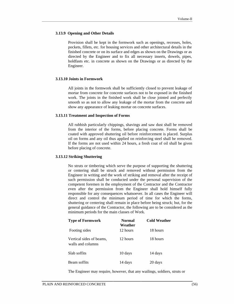
Volume-II
3.13.9 Opening and Other Details
Provision shall be kept in the formwork such as openings, recesses, holes, pockets, fillets, etc. for housing services and other architectural details in the finished concrete or on its surface and edges as shown on the Drawings or as directed by the Engineer and to fix all necessary inserts, dowels, pipes, holdfasts etc. in concrete as shown on the Drawings or as directed by the Engineer.
3.13.10 Joints in Formwork
All joints in the formwork shall be sufficiently closed to prevent leakage of mortar from concrete for concrete surfaces not to be exposed in the finished work. The joints in the finished work shall be close jointed and perfectly smooth so as not to allow any leakage of the mortar from the concrete and show any appearance of leaking mortar on concrete surfaces.
3.13.11 Treatment and Inspection of Forms
All rubbish particularly chippings, shavings and saw dust shall be removed from the interior of the forms, before placing concrete. Forms shall be coated with approved shuttering oil before reinforcement is placed. Surplus oil on forms and any oil thus applied on reinforcing steel shall be removed. If the forms are not used within 24 hours, a fresh coat of oil shall be given before placing of concrete.
3.13.12 Striking Shuttering
No struts or timbering which serve the purpose of supporting the shuttering or centering shall be struck and removed without permission from the Engineer in writing and the work of striking and removal after the receipt of such permission shall be conducted under the personal supervision of the competent foremen in the employment of the Contractor and the Contractor even after the permission from the Engineer shall hold himself fully responsible for any consequences whatsoever. In all cases the Engineer will direct and control the minimum period of time for which the forms, shuttering or centering shall remain in place before being struck; but, for the general guidance of the Contractor, the following are to be considered as the minimum periods for the main classes of Work.
Type of Formwork Normal Cold Weather
Weather Footing sides 12 hours 18 hours
Vertical sides of beams, 12 hours 18 hours walls and columns
Slab soffits 10 days 14 days
Beam soffits 14 days 20 days
The Engineer may require, however, that any wailings, soldiers, struts or
PLAIN AND REINFORCED CONCRETE (56)

Volume-II
other timbers or supports, the removal of which may cause the transference of load to the finished work, to be kept in place for three weeks after the placing of the concrete.
Form removal time can be reduced considerably if high early strength concrete is used in structures. In such case contractor will have to submit proposal along with test results of high early strength concrete for the approval of Engineer.
3.13.13 Injury or Damage
The Contractor shall be responsible for any injury to the Work and any consequential damages caused by or arising from the removal and striking of forms, centering and supports, due to striking too soon. Any advice, permission or approval given by the Engineer relative to the removal and striking of forms, centering and supports shall not relieve the Contractor from the responsibilities herein defined.
3.13.14 Treatment after Removal of Forms
Any minor surface honey-combing or other irregularities are to be properly made good immediately upon the removal of the formwork and the surface made good to the satisfaction of the Engineer at the Contractor's own expense. Any small voids shall be neatly repaired with cement mortar consisting of one part of cement to two parts of sand and the whole surface rubbed over with carborundum stone and cement wash to bring the whole to a smooth and pleasing finish and uniform color.
3.13.15 Types of Finish
Where details of the required finishes are not specified separately the following shall apply:
Type A - Rough Finish for Buried or Rendered Work
This finish is obtained by the use of properly designed formwork or moulds of closely jointed saw or wrought boards or other suitable material. The surfaces will be imprinted with the grain of the boards and their joints. In addition, small blemishes caused by entrapped air or water may be expected, but the surface should be free from voids, honeycombing or other large blemishes. The holes left for formwork bolts shall be filled. Fins and irregularities projecting more than 3mm shall be cleaned off.
Type B - Normal Finish Exposed Work
This finish is obtained by the use of properly designed forms of closely jointed wrought boards, plastic, steel or other suitable materials, provided that the surfaces shall be free from the imprint of the forms. Small blemishes caused by entrapped air or water may be expected, but the surface should be free from voids, honeycombing or other large blemishes. The holes left for formwork bolts shall be filled. Fins and other projections shall be removed and all blemishes filled with cement and fine aggregate paste. Care shall be taken in the choice of any release agent used, to ensure that the finished concrete surface is not permanently stained or discoloured.
PLAIN AND REINFORCED CONCRETE (57)
Volume-II
Type C - Superior Finish Exposed Work
This finish can only be achieved by the use of high quality concrete any by using properly designed forms having a hard, smooth surface. The concrete surfaces should be smooth with true, clean arises. Only very minor surfaces blemishes should occur and there should be no staining or discoloration from the mould oil or curing agent.
The surface shall be free from the imprint of wood grain. Un- faced wrought boarding or standard panels shall not be used. The material for the form shall be provided in large sheets and arranged in an approved uniform pattern: joints between sheets shall be arranged to coincide with architectural features, sills or heads of windows or changes in direction of the surface; all joints between sheets shall be accurately aligned in the plane of the sheets. Bolt holes are not allowed.
Other types of Finish
These shall include any finish different from A, B and C that requires the use of special forms or linings, the use of a different concrete mix near the surface, grinding, bush hammering or other treatment. If any of these special finishes is required it shall be fully specified on the drawings.
Whichever method the Contractor uses for obtaining each finish, the same method shall be used for the remainder of the work.
Remedial treatment to the finish of the concrete, additional to that specified above, requires the approval of the Engineer.
Finish of Unformed Surfaces
The finish of unformed surfaces shall be tampered floated, toweled or brushed as defined below and shown on the Drawings or as directed by the Consultant:
TF Tamped: Surfaces shall be formed by leveling and tamping the concrete to produce a uniform plain or ridged surface, surplus concrete being struck off by a straight edge immediately after compaction. It is also the first stage of the following finishes.
FF Floated: Shall be a uniform surface which has been worked no more than is necessary to remove screed marks by hand with a wood or steel float of a type approved by the Engineer. The surface shall not be floated until the concrete has hardened sufficiently.
ST Steel Toweled: Shall be hard, smooth finish free from trowel marks formed with a steel trowel under firm pressure. Toweling shall not commence until the moisture film has disappeared and the concrete has hardened sufficiently to prevent excess laitance from being worked to the surface. If laitance is brought to the surface it shall be removed.
BR Brushed: Shall be formed by first producing a floated finish and then, before the concrete has hardened, by drawing a wire broom over the concrete surface at right angles to the traffic flow to give an average texture depth of 1mm.
PF Power Float: Shall be a uniform surface which has been worked no more
PLAIN AND REINFORCED CONCRETE (58)
Volume-II
than is necessary to remove screed marks with a power float of a type approved by the Engineer. The surface shall not be floated until the concrete has hardened sufficiently.
Direct Finishing: Where specified, direct finishing consisting of dry-shake or granolithic application shall be carried out in accordance with the specialist manufacturer's details.
Plastic Cracking: If plastic shrinkage cracking occurs, the construction affected shall be rectified and the Contractor shall take all necessary steps to prevent a recurrence. Rectification method and results shall be subject to the approval of the Engineer.
Random Drying Shrinkage Cracking and Plastic Settlement Cracking: If any cracking of the concrete occurs in an uncontrolled manner, the construction affected shall be rectified and the Contractor shall take all necessary steps to prevent a recurrence. Rectification method and results shall be subject to the approval of the Engineer.
Curing compound shall not be used on concrete surfaces which are to be bonded with concrete later (e.g. at construction joints) unless all such surfaces are broken away to completely remove the membrane prior to further concreting at the joint. Furthermore, curing compounds shall not be allowed to contaminate reinforcement.
As membrane curing compounds may affect the subsequent treatment or finish of the surface of the concrete, their use requires to be approved by the Engineer before they are adopted. The Contractor is to supply sufficient technical data regarding his suggested compound to enable the Engineer to assess its suitability.
Un-formed Surfaces: Within ten minutes of placing and compaction, the un-formed surfaces of the concrete shall be completely covered with reflective polythene sheeting with substantial close fitting taped laps. The polythene sheeting may be raised a short distance above the concrete so that it does not mark the surface. At the edges of the pour, the polythene shall drape over the forms and it shall be securely fixed to prevent billowing due to the wind.
Within three hours of placing and compaction the polythene shall be quickly removed and replaced with wet hessian laid onto the concrete surface. The polythene shall then be replaced and secured as above.
The polythene sheeting and hessian may be temporarily removed for surface finishing of the concrete.
The hessian shall be kept continuously damp during the curing period. Inspections shall be carried out at intervals not exceeding 6 hours.
Protective measures shall be maintained throughout the curing period to shade the concrete from direct sunlight and protect it from the wind by the use of windbreaks.
Formed Surfaces:
Formwork shall be shaded and continuously wetted to prevent high temperatures accelerating the curing. As soon as possible, forms shall be loosened to enable curing water to run down inside them. Within half an hour of stripping, formed surfaces shall be covered by wet hessian and
PLAIN AND REINFORCED CONCRETE (59)
Volume-II
reflective polythene and then treated in accordance with the requirements stated above for un-formed surfaces.
3.14 Construction Joints
Construction joints shall be located as indicated on the Drawings and/or as approved or directed by the Engineer. Prior to construction of any structure, the Contractor shall submit a proposal showing location of construction joints and sequence of construction to suit his concreting programmed for the approval of the Engineer. Joint in columns shall be made at the underside of the deepest beam framing thereto. Beam stems and slabs shall be poured monolithically unless allowed otherwise by the Engineer in writing. Joints not specified or shown on the Drawings if so required and approved by the Engineer, shall be so located as to least impair the strength and appearance of the Work. Except and where indicated on the Drawings, no jointing shall be made in footings or foundations without written approval of the Engineer. Construction joints shall be at right angles to the member and shall be formed against firm stop boards. The stop board shall be removed as soon as possible after placing the concrete but without the risk of movement of the concrete and the concrete surface shall be well brushed with a hard brush and washed off with a spray of water, two to four hours after casting, to expose the aggregate and provide key for the next pour.
In all water retaining structures and other substructure pits and trenches, P.V.C. or any other approved water stops shall be provided at the construction joints in the manner shown on the Drawings and/or approved by the Engineer.
Whenever a section of concrete is left unfinished, for any reasons with the approval of the Engineer, leaving surface which will be hard-set before additional concrete can be joined to it, such dovetails, grooves or other bonds shall be provided as may be necessary to ensure a good bond with the new work, at the cost of the Contractor. Before deposition fresh concrete upon or against any concrete which is already set, the surface of the set concrete shall be roughened with a cutting tool, any laitance removed, thoroughly cleaned from all foreign matter, well watered and covered with approved bonding agent and cement grout, and special care shall be taken to ram the fresh concrete thoroughly up and against the set concrete; and, if deemed necessary by the Engineer, the joints shall be reinforced with steel bars or dowels to be all furnished and done by the Contractor without any additional cost.
3.15 Concrete Floor Slab Finishing
Concrete slabs shall be finished as described herein. In preparation for finishing, floor slabs shall be struck off to the required level at or below the elevation or grade of the finished floors as shown on the Drawings. Floors shall be leveled with a tolerance of 1 mm in 1m. Where drains occur, the floor surface shall be pitched to the drains as indicated on the Drawings or as directed by the Engineer.
3.15.1 Monolithic Finish
All concrete surfaces in floors, except where other finish is specified, shall be finished by steel floats or straight edges to bring the surface to the required finish level as shown on the Drawings. While the concrete is still green, but sufficiently hardened to bear a man’s weight without deep imprint, it shall be wood floated to a
PLAIN AND REINFORCED CONCRETE (60)
Volume-II
true even plane with no coarse aggregate visible. Sufficient pressure shall be used on the wood floats to bring moisture to the surface. The concrete shall then be hand toweled to produce smooth impervious surface free from trowel marks. If necessary, the process shall be repeated so that the final finish shall produce ringing sound from the trowel. No separate payment shall be made for finishing floor slabs in the aforementioned manner.
3.15.2 Concrete Topping
Where indicated on the Drawings, base slab under concrete topping shall receive a screed finish. After the base slab is thoroughly cured and when directed, concrete topping shall be laid to the thickness as indicated on the Drawings in alternate panels of suitable sizes as directed by the Engineer.
3.16 Anchor bolts, Inserts, Sleeves, Chases, Recesses, Steel Frames
The Contractor shall provide chases and openings required for other sections of the Works and will cooperate and coordinate with other trades in placing their pipes, ducts, and other built-in items as the Work proceeds, entirely at his own cost and risk.
The Contractor shall furnish and place in position accurately, as shown on the Drawings, all inserts, sleeves, chases, recesses, etc., supplied by the Contractor, subcontractors or other contractors, as directed. Full cooperation and coordination shall be maintained with other contractors, subcontractors in this regard.
3.17 Waterproof Concrete
Waterproof concrete shall consist of structural concrete as specified herein and with the addition of an approved waterproofing additive. This shall be mixed in accordance with the manufacturer's instructions and as detailed in the Bill of Quantities.
Contractor's attention is drawn to the special care required for casting roof framing, ponds, swimming pools and all underground structures including basement floor, retaining walls, sumps, pits, etc. These are all designed to ACI 350-06, Code Requirements for Environmental Engineering Concrete Structures for water retaining structures. The Contractor shall ensure that workmanship and curing is up to the required standard. The Contractor shall take full responsibility for ensuring that the resulting construction is completely watertight and free from penetration of moisture.
When in the opinion of the Engineer, damp patches and/or leakage of water in the finished work are due to failure of the Contractor to comply with this specification, the affected work shall be made good at the Contractor's expense.
Water stop shall be provided in all construction joints and the type of water stop will be as specified or to the approval of the Engineer. All water stops will be joined by welding strictly in accordance with the manufacturer's recommendations and all multiple joints and special intersections shall be manufactured by the supplier.
Before commencement of work, the Contractor shall obtain the Engineer's approval of the methods to be used to support and maintain the water stop in the correct location while the concrete is placed and also the layout and form of all additional construction joints other than those shown on the drawings. Unless indicated
PLAIN AND REINFORCED CONCRETE (61)
Volume-II
otherwise on the drawings, all construction joints in waterproof concrete shall be formed incorporating water stops to Engineer's approval.
All service holes cast in shall incorporate sleeves with puddle flanges and temporary openings for services should incorporate water stops.
Care shall be taken at all times to ensure that water stops are not perforated or damaged in any way and the concrete shall be carefully placed and compacted around the water stop to ensure void free impervious concrete.
All kickers or starter plinths to walls (if used) on the periphery of the watertight construction shall be cast monolithically with the base.
The formwork shall comply with this Specification and in addition any bolt or fastening embedded in or passing through the concrete shall be to the approval of the Engineer and not impair the water-tightness of the structure. The use of through bolts and sleeves is strictly prohibited.
Special attention shall be given to the elimination of shrinkage or thermal cracking. The size of any bay or slab or wall and sequence of pouring shall be such as to minimize cracking.
Slotted inserts or sockets cast into the structural concrete shall be provided for all fixings including services. The cutting of holes in watertight concrete is strictly prohibited.
The Contractor is completely responsible for making all basements and swimming pools absolutely watertight. If any leakages or moist patches occur, the cost of any repairs, etc. to make the basement and swimming pool fully watertight will be borne by him. The Contractor is to give a ten year guarantee for water-tightness, reckoned from the date of completion of roof framing, basement and swimming pool. The form of guarantee is to be to the satisfaction of the Client. Should any leaks or dampness occur during the Guarantee period of ten years, the Contractor shall, at no cost to the Client, immediately re-waterproof the defective area or areas and make good all damages to surface finishes such as plaster, painting, paneling, tiling, etc. electrical or other installations or other property, caused by leaks or dampness or reimburse the Client for making good such damages. Water-tightness of swimming pools shall be inspected and tested in accordance with BS 8007: 1987.
3.18 Cleaning and Removal of Rubbish
On completion of Works herein, the Contractor shall remove all concrete debris, rubbish, shuttering materials, scraps etc., from the vicinity of the structures completed. All areas shall be cleaned to the satisfaction and approval of the Engineer. The rubbish shall be disposed off within or outside the Site premises free of cost as directed by the Engineer.
3.19 Tolerances
The structure shall be built to dimensions and levels shown on the Architect's drawings. Deviation from true positions and/or levels will be accepted only if they do not affect the finished dimensions, positions and levels as shown on the Architect's drawings.
PLAIN AND REINFORCED CONCRETE (62)
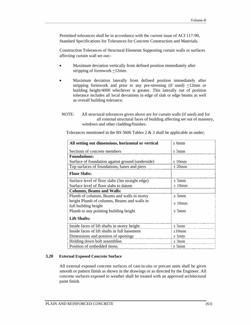
Volume-II
Permitted tolerances shall be in accordance with the current issue of ACI 117-90, Standard Specifications for Tolerances for Concrete Construction and Materials.
Construction Tolerances of Structural Elements Supporting curtain walls or surfaces affecting curtain wall set out:-
Maximum deviation vertically from defined position immediately after
stripping of formwork +12mm.
Maximum deviation laterally from defined position immediately after stripping formwork and prior to any pre-stressing (if used) +12mm or building height/4000 whichever is greater. This laterally out of position tolerance includes all local deviations in edge of slab or edge beams as well as overall building tolerance.
NOTE: All structural tolerances given above are for curtain walls (if used) and for all external structural faces of building affecting set out of masonry,
windows and other cladding/finishes.
Tolerances mentioned in the BS 5606 Tables 2 & 3 shall be applicable as under;
All setting out dimensions, horizontal or vertical ± 6mm
Sections of concrete members ± 5mm Foundations: Surface of foundation against ground (underside) ± 10mm Top surfaces of foundations, bases and piers ± 20mm
Floor Slabs:
Surface level of floor slabs (3m straight edge) Surface level of floor slabs to datum Columns, Beams and Walls: Plumb of columns, Beams and walls in storey height Plumb of columns, Beams and walls in full building height Plumb to any pointing building height
Lift Shafts:
± 5mm ± 10mm ± 5mm ± 10mm ± 5mm
Inside faces of lift shafts in storey height ± 5mm Inside faces of lift shafts in full basement ±10mm Dimensions and position of openings ± 5mm Holding down bolt assemblies ± 3mm Position of embedded items. ± 5mm
3.20 External Exposed Concrete Surface
All external exposed concrete surfaces of cast-in-situ or precast units shall be given smooth or pattern finish as shown in the drawings or as directed by the Engineer. All concrete surfaces exposed to weather shall be treated with an approved architectural paint finish.
PLAIN AND REINFORCED CONCRETE (63)
Volume-II
3.21 Water Retaining Structures
3.21.1 Scope of Work
The Work covered under this subsection of Specifications consists of furnishing all labour, tools, scaffolding, hoisting equipment, appliances and materials of every kind and character; and in performing all operations in connection with procurement, transportation and delivery, supply and installation of special provisions for water retaining structures to ensure water tightness in all possible respects in strict accordance with requirements of Drawings and Bill of Quantities as specified herein, and to the entire satisfaction of the Engineer and subject to the terms and conditions of the Contract.
3.21.2 General
a) Special consideration shall be given to the control of cracking and
the provision of dense impervious concrete. Special consideration will also be given to the design of the concrete mix and to the supervision of the placing and compacting in order to provide a dense impermeable concrete. The mix shall be of the stiffest consistency having a workability which will ensure that it can be satisfactorily placed in the formwork and compacted without risk of segregation, honey-combing, sweating or bleeding. Special care shall be given to the method and order of placing the concrete and to the construction of joints in order to achieve full continuity and complete water tightness.
b) The Contractor shall maintain an accurate record of ambient
temperature at Site.
c) Ambient temperature shall be measured using mercury thermometers or other thermometers acceptable to the Engineer.
d) Throughout the concrete work, the Contractor shall employ full time
on the Works suitable number of qualified and experienced Engineers whose sole duties shall be as follows;
Design of concrete mixes Control of quality of concrete Supervision of mixing, transporting, placing, compacting,
finishing, curing and protecting concrete including thermal control of concrete pours.
Supervision of sampling and testing.
Preparation and submission of test certificates and reports.
Compilation and keeping of record.
Such other duties as the Engineer may direct.
3.21.3 Cement Content
The minimum cement content for all water retaining structures shall be 385 kg/m3 and the maximum cement content of 500 kg/m3. The maximum water-cement ratio shall not exceed 0.40.
PLAIN AND REINFORCED CONCRETE (64)
Volume-II
3.21.4 Admixtures
a) Suitable admixtures from Sika, Fosroc, BASF, Schomburg or other
equivalent approved manufacturer may be used in concrete mixes with the prior approval of the Engineer. The amount of admixtures added to each batch of concrete requires careful control and shall be added in the doses as recommended by the manufacturers and approved by the Engineer. The cost of the admixtures shall be deemed to be included in the unit rates.
b) For use of an admixture, the information required by the Engineer
shall be submitted to him for each admixture for approval.
3.21.5 Junction of Floor and Wall
Where the walls are designed to be monolithic with the bottom slab and beam system, a continuous up stand section of the wall shall be cast at the same time integrally with slab. A suitable arrangement of the reinforcement and formwork shall be made to facilitate this. The height of this up stand, which shall not be less than specified shall be sufficient to enable the next lift of formwork to fit tightly and avoid leakage of the cement paste from the newly deposited concrete. Such leakage, where it occurs is liable to cause porosity in the finished concrete and is not acceptable.
3.21.6 Pipes through Walls and Floor
When it is necessary for pipes to pass through a wall or bottom floor, it is preferable to cast the pipes into the panel when it is concreted. If this is not practicable, it will be necessary to box out. In either case, it is desirable that the position of the pipe shall not coincide with a joint. When an opening has been boxed out the sides of the opening shall be treated as construction joint.
All piping and fittings shall be tested as a unit for leaks immediately prior to concreting. The testing pressure above atmospheric pressure shall be fifty (50) percent in excess of the pressure to which the piping and fittings may be subjected but the minimum testing pressure shall be not less than 1.0 N/mm2 (150 psi) above atmospheric pressure. The pressure test shall be held for four hours with no drop in pressure except that which may be caused by air pressure.
No liquid, gas or vapor, except water not exceeding 32°C nor 0.135 N/mm2 pressure, is to be placed in the pipes until the concrete has thoroughly set.
The concrete cover of the pipes and fittings shall be not less than 1½ inch. The piping and fittings shall be assembled by welding, brazing, solder seating, or other equally satisfactory method. Screw connections shall be prohibited. The piping shall be so fabricated and installed that it will not require any cutting, bending, or displacement of the reinforcement from its proper locations.
Drain pipes and other piping designed for pressure of not more than 1 psi above atmospheric pressure need not be tested.
PLAIN AND REINFORCED CONCRETE (65)
Volume-II
3.21.7 Arrangement of Reinforcement
Particular attention shall be given to the spacing of reinforcement at points so that access to the concrete surface can be provided to enable it to be prepared to receive the following batch of concrete.
The length of lap and anchorage provided shall be in accordance with the requirements of ACI 318.
3.21.8 Formwork
Ties used to secure and align the formwork shall not pass completely through any part of the water retaining structure unless effective precaution can be taken to ensure water tightness after their removal. The ends of any embedded ties shall have cover equal to that required for the reinforcement. The gap left from the end of the tie to the face of the concrete shall effectively be sealed. Any steel left in the structure shall be adequately protected against corrosion.
3.21.9 Construction
The degree of success in achieving a watertight structure depends on the quality of workmanship in making and placing concrete, good on site organization, proper ground water control, clean and dry excavation, careful storage of materials, close-fitting formwork, correctly fixed reinforcement and clean joints.
It is essential that the concrete, when placed, is thoroughly compacted to form a dense uniform mass. The mix shall be of adequate workability and compaction by vibration. Immediately after the removal of formwork, the concrete surface shall be carefully inspected and any defects made good as soon as possible.
3.21.10 Curing
Even after minimum curing period specified in the clause pertaining to curing in the Specifications for Plain and Reinforced Concrete, it may be desirable to prevent drying of the concrete and to restrict the range of temperature changes which it is subjected to.
3.21.11 Inspection and Repair
As soon as possible after completion of the water retaining structures, the structure shall be examined for defects which may lead to water penetration or leakage. All openings exposed to the weather shall be covered and all water on the floors shall be removed and the surfaces allowed to dry before the inspection. Water retaining structures shall be tested in accordance with BS: 5337 or other approved standard.
Defects that are revealed through which water may penetrate or leak shall be repaired by the Contractor to the entire satisfaction of the Engineer. Where internal repairs are to be made, the areas of weakness shall be isolated by
PLAIN AND REINFORCED CONCRETE (66)

Volume-II
suitable means and any cracks sealed by an approved process by a specialist contractor experienced in this type of work.
3.22 Inspection and Making Good
3.22.1 Inspection of Defects
(i) Surfaces exposed after stripping shall be inspected by the Concrete
Engineer of the Contractor, together with the Engineer. The following standards shall be valid for the assessment of the concrete quality:
The appearance of the concrete surface must conform to the
specified requirement of finish.
The concrete surface must be uniformly smooth, even and free of ridges and other irregularities,
The concrete must have a pore-free, dense surface on all sides with no evidence of segregation or inadequate compaction,
No reinforcing bars may be exposed or signs be present, which indicate an inadequate concrete cover of the reinforcing bars,
No hair cracks shall be visible.
(ii) During the inspection, the Engineer will determine the type and extent of defects to be eliminated and ascertain if cracks are still moving.
The Contractor is obligated; if necessary and applicable, undertake the following in accordance with para (iii) below:
To expose reinforcing bars, which apparently have an
inadequate concrete cover, in the area determined by the Engineer and to bend them inward through suitable measures.
To caulk out honeycombs and similar defective spots, which are traceable to segregation of the concrete.
To pressure-grout damaged areas, cracks, etc.,
To seal all hair cracks of a measured width of more than 0.05 mm, with suitable and recognized epoxy resin material.
To seal all holes resulting from the removal of formwork bolts and the like.
To demolish and reconstruct such structural concrete members which cannot satisfactorily be repaired or which are otherwise unfit for the Works in the Engineer's opinion.
To propose and apply a proven system or measures according to the type and extent of the defect, as set out in para (iii)
PLAIN AND REINFORCED CONCRETE (67)
Volume-II
below in order to achieve a result and appearance acceptable to the Engineer.
3.22.2 Patching & Repair
(i) Apply a cementitious repair material approved by the Engineer. The
proprietary cementitious repair material, bonding agent and application method shall meet the following criteria:
The repair material shall be cementitious and shall possess a
similar thermal co-efficient to the base concrete.
The repair material shall have shrinkage compensating characteristics.
The bonding agent shall be compatible with both the existing concrete and the repair material.
The system shall exhibit long term durability.
The proprietary cementitious repair material and bonding agent shall be stored, applied and cured in accordance with the manufacturer’s requirements and recommendations.
Finish the cementitious repair material to a straight line with the existing surface, to the profile of the original undamaged concrete section.
The Engineer may direct that where the cover to the existing reinforcing is insufficient, the repair may protrude beyond the existing concrete face. The protruding edges of the repair shall then have a 45° chamfer, and shall be horizontal or vertical to provide a pleasing finish.
The Engineer’s evaluation of the Contractor’s proposed materials and application method shall be based on the above criteria.
The Contractor shall submit full details and specifications of his proposed materials and installation methods to the Engineer for approval prior to commencement of work.
This shall include certificates of approval from competent authorities to prove their suitability.
(ii) Patching work shall begin at the latest 24 hours after stripping,
however it shall in no case be undertaken prior to carrying out the joint inspection of the concrete by the Contractor and the Engineer.
(iii) Patching and repair work shall be executed only through qualified
personnel using high quality and recognized materials, e.g., concrete and cement or special mortar. A special bonding agent such as suitable epoxy resin and the like, of first class quality shall be used where appropriate, to also ensure good bonding and adequate denseness in the joints.
PLAIN AND REINFORCED CONCRETE (68)
Volume-II
(iv) All costs for repair and patching work are to be borne by the Contractor.
3.22.3 Sealing of Cracks
(i) Cracks detected in concrete members cast by the Contractor, are to be
sealed according to the directives of the Engineer, provided cracked structural concrete members are not rejected by the Engineer.
(ii) All cracks identified by the Engineer as requiring remedial work
shall be sealed by injection epoxy to full depth of crack from the exposed surface. The surface of the cracks must be cleaned. Injection nipples are to be provided at 150mm to 300mm intervals and the remaining surfaces of the cracks are to be sealed with suitable epoxy compound. Prior to the injection, the crack shall be cleaned of dust by blowing oil free and clean compressed air through all the injection nipples. In case of cracks in vertical or sloped walls, the injection must start at the lowest nipple.
(iii) The epoxy resin shall be a suitable product from Sika, Fosroc ,
BASF or other approved manufacturer, complying with ASTM C-881, and as approved by the Engineer. Epoxy injection shall be in accordance with the manufacturers written instructions. Note that on completion of injection and curing of the epoxy, the nipples are to be removed and the exposed surfaces ground or scraped smooth to provide a smooth, even and tidy finish restoring the original profile).
3.23 Measurement and Payment
3.23.1 Formwork
All costs for formwork must be included in the concrete prices and will not be measured and paid separately. The prices shall include all related costs for the different materials and performances, erection, strengthening and removal of shuttering relative to the formwork.
3.23.2 Reinforcement
a) Reinforcing bars will be measured as per Drawings of structure in
consideration of nominal weight (as per ASTM A615) of each size of bar and paid per ton at the unit rate entered in the Bill of Quantities.
b) The prices shall include all costs involved with the supply,
transportation, storage and protection, the cutting, bending, wastage and placing, inclusive of concrete spacers, supports, stands, tying into position, etc.
c) Assembly stands, spacers etc., whether designated in the Drawings
or not or otherwise demanded by the Engineer will not be measured and paid separately.
d) If installed reinforcement must be dismantled under certain
circumstances or where additional reinforcing bars are to be provided
PLAIN AND REINFORCED CONCRETE (69)
Volume-II
on Engineer's instruction (due to less unit weight of steel bars,) the Contractor is not entitled to any compensation, if such additional supplies and/or performances are required and demanded by the Engineer due to the Contractor's faulty execution of the respective work.
3.23.3 Concrete
a) Concrete works shall be measured and paid for as per theoretical
volumes calculated on the basis of the Drawings, or as otherwise approved by the Engineer and paid at per cubic meter at the rates entered in the Bill of Quantities.
Recesses (e.g. openings in slabs, break-through and the like) with an individual volume of more than 0.10 sq. m. or 0.05 cu. m. shall be deducted.
b) The prices for concrete works shall include all cost for the complete
work and are not limited to the cost of formwork, its support, anchoring, chamfers, construction joints etc., the required scaffolding, false-work, temporary works, post-treatment and, if necessary, repair of concrete, all preliminary and routine tests, as well as the required technical checks and drawings for Temporary Works in connection with the concrete works.
c) The cost for special finishing of exposed concrete surfaces such as
fair-faced finish etc. shall be included in the unit price applicable to the respective structural member and will not be compensated for separately.
d) The cost of all concrete admixtures and additives shall not be paid
for separately and is deemed to be included in the unit rates of respective items of the BOQ.
3.23.4 Joints
a) Expansion Joints
Expansion joints shall be measured and paid for separately per running meter of accepted lengths, according to the Drawings / bill of quantities. The prices shall include all costs for the different materials and performances relative to the laying and sealing of the joints.
b) Dummy Joints
Dummy joints required by the Contractor with the Engineer's consent for the sound execution of the Works will not be paid for separately, but the costs involved are deemed to be covered by the concrete prices applicable to the respective structural member.
c) Construction Joints
PLAIN AND REINFORCED CONCRETE (70)

Volume-II
Construction joints will not be measured and paid for.
The Contractor is deemed to have covered the costs for all related supplies and performances by surcharges included in the respective concrete prices.
However, the cost of PVC water stop shall be measured and paid for separately per running meter of accepted lengths.
3.23.5 Tamping of Equipment and Grouting of Recesses
The costs resulting from materials and performances in connection with the tamping of installed items or the grouting of recesses are deemed to be included in the prices for the supply and/or installation of the respective items, and will therefore not be separately compensated for.
PLAIN AND REINFORCED CONCRETE (71)
Volume-II
SECTION – C 04
PLASTERING AND RENDERING
Volume-II
SECTION C 04
PLASTERING AND RENDERING
4.00 Plastering and Rendering
4.01 Scope of Work
The Work covered by this section of the Specifications consists of furnishing all plant, tools, labour, appliances, materials and performing all operations in connection with lathing, plastering and rendering, complete in strict accordance with this section of the Specifications and the applicable drawings, as per instructions of the Engineer and subject to the terms and conditions of the Contract.
4.02 General
4.02.1 Except as may be otherwise shown or specified, all plaster and rendering shall be
cement sand plaster. Plastered ceilings and walls shall include partitions, piers, columns, beams, ceilings, plastered jambs and other returns, reveals, and backs of recesses and alcoves, and joints and heads of windows and doors, unless otherwise specified or shown on the Drawings. Plaster on walls shall be carried down to dado, skirting and projected bases. Plasterwork shall also include all plasterwork on and under concrete surfaces to be left exposed and concrete not specified to be left fairfaced, as indicated on Drawings.
4.02.1 A 13mm thick render coat shall be applied to walls with a slightly roughened surface
where wall finishes of applied nature, such as ceramic tiles, marble tiles, terrazzo tiles etc., are to be installed over wall surfaces.
4.03 Materials
4.03.1 Portland cement shall be as mentioned in Section-04, Plain & Reinforced concrete.
4.03.2 Sand shall be clean and free from dirt to comply with the requirements of ASTM C-
144.
4.03.3 Water shall be clean and free from oils, acids, alkalis, salts and organic or other injurious matter and as described in Section-04 Plain & Reinforced concrete.
4.03.4 Mortar plasticizer shall comply with BS 4887 and shall be used in accordance with the manufacturer’s instructions.
4.04 Mixing of Plaster
Except where hand mixing of small batches is approved by the Engineer, mechanical mixers of an approved type shall be used for the mixing of plaster. Frozen, caked, or lumped materials shall not be used. Mechanical mixers, mixing boxes and tools shall be cleaned after mixing each batch and kept free of plaster from previous mixes. Plaster shall be thoroughly mixed with the proper amount of water until uniform in colour and consistency.
PLASTERING AND RENDERING (72)
Volume-II
Re-tempering will not be permitted, and all plaster which has begun to stiffen shall be discarded. When no plasticizer is used, plaster shall be used within 30-minutes after mixing of water, however with the use of plasticizer initial setting time will be determined and time extension shall be allowed accordingly with the approval of engineer.
4.05 Proportioning of Plaster on Internal Walls and Base Plaster
4.05.1 All plaster shall be Portland cement sand plaster, all coats of which shall be mixed in
the following proportions by volume:
One part cement: 4 parts sand.
4.05.2 All coats of plaster in water retaining structures shall be waterproofed by the addition of an approved waterproofing additive/admixture from Sika, Fosroc, Master Builders, Schomberg or equivalent.
4.06 Preparation of Surfaces of Plaster
4.06.1 Surfaces to receive plaster shall be brushed to remove all loose particles, dust,
laitence, efflorescence, etc. and any projecting fins on concrete surfaces shall be hacked off.
Glossy or greasy surfaces shall also be suitably cleaned and chipped off to remove all traces of mould oil.
4.06.2 Where unduly smooth in-situ concrete surfaces are encountered, such
surfaces must be hacked properly before applying plaster.
4.06.3 Surfaces shall thoroughly be sprayed with water and allow free water to evaporate before plaster is applied.
4.06.4 Irregularities in the surfaces to be plastered shall be filled with cement mortar
24 hours before plastering is commenced.
4.06.5 Before plastering is commenced, all junctions between differing materials shall be reinforced. This shall apply where walls join columns and beams particularly where cracks are likely to develop and places directed by the Engineer. The reinforcement of such joints shall consist of a strip of galvanized expanded metal lathe/mesh, atleast 6” wide, which shall be plugged, nailed or stapled to the surfaces to be plastered at the intervals not exceeding 12”. The joints in mesh shall be lapped minimum 6”.
4.06.6 It shall be responsibility of the Contractor to ensure that all electrical
conduits, pipes, concealed or embedded items, ducts, brackets, doors, window and ventilator frames, and all other fixtures on walls, ceilings, columns or required elsewhere have been fixed in position before the plastering is commenced.
PLASTERING AND RENDERING (73)
Volume-II
4.06.7 Cuttings and chasings in the brickwork shall be repaired as per the instructions of the Engineer atleast twenty four hours before the plastering is commenced.
4.07 Application of Plaster
4.07.1 The Contractor shall not start any work till the surfaces are inspected by the Engineer. In case, any plaster work is done without obtaining the consent of the Engineer, the Engineer shall have the right to order removal of all such work and cleaning and preparation of the surfaces to his full satisfaction and the Contractor shall comply with such orders without any delay and redo the work at his own cost. No extra/additional payment shall be made to such work.
4.07.2 All surfaces to be plastered shall be treated with cement slurry as a base coat
for proper bond. Any approved bonding agent may also be used as an alternative to cement slurry with approval of the Engineer.
4.07.3 Plaster to internal and external surfaces shall be applied in the thickness
shown on the Drawings or specified elsewhere. In any case, the plaster thickness shall not be less than the specified thickness.
4.07.4 Plaster shall be applied in two (2) coats on masonry and concrete surfaces
where thickness is more than 19mm. The thickness of each coat shall not exceed 19mm.
a. In case of 2 coats, the first coat or the render coat shall be full and thick and
shall be applied with sufficient force to form good keys. The under coat shall be roughened and cross-scratched upon attaining its initial set to provide a proper bond to the next coat and shall be kept damp with a fog spray.
b. Finish coat shall not be applied until the under coat has seasoned for 2 days.
Just before application of the finish coat, the under coat shall again be wetted evenly with a fog spray.
Finish coat shall be of smooth finish or as directed by the Engineer.
The finish coat shall be kept moist with a fog spray for atleast 2 days and thereafter shall be protected against rapid drying until properly and thoroughly cured.
4.07.5 Plastering shall be executed in a neat workmanlike manner and shall be
finished off with a wood or steel float, straight and plumb and shall not have wavy surface. The surface shall be of even texture and entirely free from all marks. The edges and corners shall represent a straight line. All the arrises shall be rounded to 6 mm (¼”) radius unless otherwise specified. Plastering shall neatly be made good around pipes or fittings, corners etc.
PLASTERING AND RENDERING (74)

Volume-II
4.07.6 As far as practical, plastering shall not be commenced until all mechanical, electrical and plumbing items, conduits, pipes, fittings and fixtures have been installed in their sequence of operations.
4.07.7 Plaster is to be maintained in moist condition for atleast four days after it has
developed enough strength not to be damage by water.
4.07.8 Plaster stops angles- beads and corner of expanded metal shall be used for protection of arrises, edges and plaster ends as shown on the Drawings and as directed by the Engineer.
4.07.9 Plaster containing cracks, blisters, pits, uneven surfaces discoloration or any
defects shall not be acceptable. Any such defective plaster rejected by the Engineer shall be removed and replaced in conformity with these Specifications by the Contractor at his own cost to the satisfaction and approval of the Engineer. No extra payment shall be made for any defective or rejected work.
4.08 Sampling of Plaster
Samples may be taken by the Engineer at any time from plaster work in place. Areas represented by samples which show oversanding or not as per specified ration will be rejected.
4.09 Patching
Plaster containing cracks, blisters, pits, checks, or discoloration will not be acceptable. Such plaster shall be removed and replaced with plaster conforming to this Specification and approved by the Engineer. Patching shall match with existing work in texture and colour to the satisfaction of the Engineer.
4.10 Concrete / Masonry Joints
All joints of concrete and block/brick walls shall be specially treated as described here or as shown on Drawings. A 6” wide approved expanded metal shall be fixed at the joints and then plaster shall be applied. The expanded metal shall be with a weight of 3.58 lbs./sq. meter.
4.11 Measurement and Payment
4.11.1 Plaster shall be measured and paid per square meter, complete and approved, at the unit rates
entered in the Bill of Quantities, including preparations, junction reinforcements, metal lathe, chamfered edges, rounding off corners etc. and in the thickness as specified in Bill of Quantities.
4.11.2 Render coat or backing plaster shall not be paid for separately but shall be deemed to be included in the rates of the finished item.
4.11.3 No extra payment shall be made, against cost of samples, cartage, testing etc, to the
Contractor, his sub-contractor supplier or vendor.
PLASTERING AND RENDERING (75)
Volume-II
SECTION – C-05
Dismantling Work

Volume-II
SECTION-C 05
DISMANTLING WORKS
5.00 SCOPE
The work covered by this Section of the Specifications consists of furnishing all plant, labor, equipment, appliances and performing all operations in connection with demolition/ dismantling and removal of existing drains, structure, asphalt road, pavement, kerbs, medians, foundations, approaches/plate forms, trees, plants, removal of services with accessories and Plain concrete / masonry structures including disposal of demolished / dismantled and removed material to designated places. Whole work shall be done in accordance with these specifications and as directed by the Engineer.
5.1 PROCEDURES
5.1.1 The method of dismantling and demolition including the sequence of operations and
any special procedural requirements shall be submitted to the Engineer for consideration not less than seven days before the work is due to begin. Demolition work shall be carried out in accordance with BS 6187, and the submittal shall include information demonstrating the Contractor's proposed methods to attain compliance.
5.1.2 The Engineer will define the limits where demolition/ dismantling and removal
activity is to be done and shall approve the procedures/methods to be adopted by the Contractor. The Contractor shall layout the boundaries/limits for Engineer’s checking and approval before commencing dismantling work.
5.1.3 Whole work shall be performed in an orderly manner and the Contractor shall take all
necessary precautions and expedients to prevent damages to the adjacent structures, installed equipment/machinery, pipes, conduits, any other installation etc. Any damage caused to the structures and installations due to negligence of the Contractor during demolition/ dismantled and removal operations shall be repaired/replaced by the Contractor at his cost and to the satisfaction of the Engineer.
5.2 DISMANTLING OF EXISTING BUILDINGS
5.2.1 The existing structure / drains shall be dismantled/demolished in such a way that the
useable materials, i.e. steel rebars etc can be used by the Owner. All safety precautions shall be exercised while execution and unusable debris shall be disposed off as per Engineer’s instructions.
5.2.2 Foundations buried or visible shall be cleared and ditches/trenches shall be refilled
with compaction to use the surface for new structure. Utilities lines shall be provided bypass or alternate routine before dismantling to ensure supply / drainage uninterrupted. The surface shall be cleaned out after dismantling and dismantled material shall be disposed off at the places as designated by the Engineer.
DISMANTLING WORKS (76)

Volume-II
5.3 REMOVAL & SHIFTING OF TREES
The trees which are to be removed shall be excavated up to roots end and removed completely their all branches etc. No structure works shall be allowed to rest on the soil containing roots or any part of it.
The trees of specified girths shall be removed / replanted as directed by the Engineer, at the designated places, these large trees shall be excavated around the tree, but not less than 200mm, in such a manner that the roots of trees should not be cut or exposed to atmosphere, sufficient native soil should remain adhesive to the roots of tree.
Immediately prior to shipping all plants shall be inspected, dug, prepared and packed with care and skill in accordance with the recognized standard practice for the kinds of plants concerned.
During transportation, all plants shall be packed adequately to ensure protection from sun, wind, climatic or seasonal injuries. Tarpaulins and other covers shall be placed over plants when they are transported by trucks for more than 10 km.
Roots system of all plants shall not be permitted to dry out at any time and shall not be exposed to excessive heat or to freezing temperature.
Immediately after digging and prior to packing in moss or other suitable materials, roots shall be dipped in a solution of humectants. All earth- balls shall be firmed and intact and contained in hessian or palm bark. Do not drop balled or bur lapped stock at any time. All balled and hessian covered plants and container growth plants shall at all times be handled by the ball or by the container and not by the plant stem. The head of each tree shall be carefully tied to prevent fracture of branches.
If soil or the habit of root growth is such that the final roots are not adequately protected, wrap exposed root systems in hessian and prevent from drying.
The moisture of retained soil shall be protected by wrapping up the hessian cloth immediately after it has been uprooted, before transporting to the designated places or at temporary stack yard. The maximum time of stacking of any tree shall not exceed more than 2 days.
The new location of tree shall be excavated up to the depth / height of root mass, so that the no any portion shall remain above the ground level, which was initially rested below ground level.
The Contractor shall arrange all required watering, pesticides, fertilizers etc. for the shifted tree, without any additional cost to employer.
5.4 DEMOLITION OF ROAD, PAVEMENT AND CONCRETE/ MASONRY WORKS
The Contractor shall demolish road pavement and concrete / masonry / flooring works to the line and depth as shown on the Drawings or as directed by the Engineer. Explosives shall not be used to remove the plain and reinforced cement concrete or any other material whatsoever. Mechanically operated breakers, concrete saws, chipping hammers or other approved methods shall be employed for cutting. Care shall be taken that existing services and structures are not damaged. It shall be the responsibility of the Contractor to replace at his cost any services, Structures damaged by the Contractor due to his negligence during cutting operations or thereafter until the whole of cut parts/areas are restored to original condition to the satisfaction of the Engineer. The Contractor shall exercise all safety precautions and
DISMANTLING WORKS (77)
Volume-II
methods while any dismantling activities and shall ensure that site is cordoned off and workers have used PPEs.
5.5 CLEARANCE OF GREEN AREA
The bushes/plants in existing green area shall be cleared off up to the roots and the surface shall smoothen and cleared from all debris and any organic material before receiving new layer.
5.6 REMOVAL OF EXISTING SERVICES/ UTILITIES
5.6.1 The Contractor shall mark all the services/ utilities falling within the ROW. After getting approval from the Engineer, the contractor shall remove all such services/ utilities as per the requirement/ specifications of the relative department whose utilities/ services are being removed/ shifted.
5.7 DISPOSAL
5.7.1 All debris materials resulting from demolition / dismantling works shall be disposed off to places designated by the Engineer in the manner of disposition required and directed by the Engineer.
5.7.2 All useable materials resulting from demolition and removal shall remain the property of the Employer and shall be stacked at designated places.
5.7.3 The Contractor shall segregate the useable materials as directed by the Engineer and stack at designated places.
5.8 MEASUREMENT AND PAYMENT
5.8.1 General
Except otherwise specified in the Contract Documents, no separate measurement and payment will be made for the works involved in dismantling and under mentioned items related to this section. The cost thereof shall be deemed to have been included in the quoted rates of the related items of the Bill of Quantities under this section.
5.8.1.1 Temporary diversion and safety measures, Demarcation/layouts etc.
5.8.1.2 Loading, unloading, transportation and disposal of demolished/ dismantled/ removed/ useable material to the place designated by the Engineer.
5.8.1.3 Permissions/approvals, if required, from the relative department and information to the stack holders.
5.8.1.4 Stacking of all useable material to the place designated by the Engineer.
5.8.1.5 Earth work
5.8.1.6 Hessian cloth, plaster of Paris etc.
5.8.1.7 Repair / finishing of adjacent component of dismantled structure.
DISMANTLING WORKS (78)

Volume-II
SECTION – C 06
PAINTING AND DECORATING
Volume-II
SECTION C 06
PAINTING & DECORATING
6.0 Painting & Decorating
6.01 Scope of Work
The Work covered in this section of the Specifications consists of furnishing all plant, tools, labour, equipment, appliances and materials and in performing all operations in connection with protective and general painting and finishing complete in strict accordance with this section of the Specifications and the applicable Drawings and subject to the terms and conditions of the Contract.
6.02 General
6.02.1 The term “Paint” as used herein includes emulsion, enamel paints, textured paint, arc
tone, stains, varnishes, seals, primers, colour washes etc. All paint colours shall be as specified by the Engineer.
6.02.1 All painting materials are to be obtained only from approved manufacturers ICI or
Berger, Nippon, Juton or equivalent as approved by the Engineer.
6.02.2 All materials shall be of the best quality in their respective categories, and shall generally be applied in conformances with the provisions of British Code of Practice 231.
6.02.3 Primers shall be those appropriate for the various kinds of building materials to
which they are applied and shall be as recommended by the manufacturer.
6.02.4 All Paints are to be used only from unopened sealed containers exactly as received from the manufacturer and shall be used in accordance with the manufacturer’s instructions. The addition of thinners, dryers, water or other additives shall only be permitted when specially recommended by the manufacturer and approved by the Engineer. The type of additive and the proportions for use shall be as recommended by the manufacturer.
6.02.5 Materials are to be thoroughly stirred as per manufacturer’s instruction in the
original containers and must be used as delivered, not adulterated in any way or mixed with different types or brands and shall be applied in accordance with the manufacturer’s instructions.
6.02.6 Undercoating shall be those recommended by the paint manufacturer as appropriate
for the finishing coat used.
6.02.7 All paint colours shall be as specified or selected by the Engineer and the Contractor shall include for all works in obtaining materials in such colours as are specified in any combination and for all matching as required.
PAINTING AND DECORATING (79)
Volume-II
6.02.8 Knotting
Knotting shall comply with BS 1336.
6.02.10 Stopping
Stopping shall be as follows;
a. Stopping for plasterwork shall be approved plastic based filler.
b. Stopping for woodwork shall be a composition of chalk, zinc, gum, colour pigments, mixed in white spirit or turpentine oil.
c. Stopping for clear finished woodwork shall be as above but tinted to match
the surrounding timber.
6.02.11 Site Environmental Conditions
a. Adapt techniques approved by the Engineer to ensure that storage, handling and execution methods suit environmental conditions that are encountered at the site, and cause no damage to the products specified in this section or to the performance of these products in use.
b. Follow recommendations of the supplier of the products.
c. Environmental conditions shall include, but shall not be limited to, ambient
temperature, humidity, moisture in the air on the products and surfaces with which they are in contact; moisture content of the products and materials with which they are in contact; and temperature of the products and the materials with which they are in contact.
d. Do not apply finishes when dust is being raised.
e. Do not apply finishes on porous surfaces such as plaster, gypsum board,
masonry and similar materials that contain over 12% moisture.
f. Do not finish wood surfaces that contain over 15% moisture.
g. Ensure that all areas in which paint is applied are well ventilated and broom clean.
6.02.12 Primers
a. Priming to woodwork shall be Acrylic Primer or Aluminium Sealer, as
appropriate from ICI or Berger or equivalent as approved by the Engineer. b. Priming to steelwork shall be Red Oxide Alkyd Primer from ICI or Berger
or equivalent as approved by the Engineer.
PAINTING AND DECORATING (80)

Volume-II
c. On all galvanized surfaces, first apply one coat of Etching primer, then one coat of Alkyd base primer from ICI or Berger shall be applied as per recommendations of the manufacturer.
d. For plaster, concrete, blockwork /brickwork ceiling boards etc. Alkali
Resisting Primer shall be used from ICI or Berger.
6.02.13 Bituminous Paint
Black bituminous paint shall comply with BS 3416 Type 1 for general use.
6.02.14 Sundry
a. Turpentine oil shall comply with BS 244 and 270.
b. White spirit shall comply with BS 245.
c. Colours for paint shall comply with BS 4800.
d. Stain for woodwork shall comply with BS 1215.
6.02.15 Paint Generally
a. Paint shall be applied with spray, roller of different grade & easy brushing, good flowing, spreading and levelling properties. These properties will be demonstrated on test specimens at the request of the Engineer. Coats that have any noticeable pull under a large brush and that show poor or fair spreading and flowing properties will not be acceptable. The grade of roller shall be selected by the Engineer at the time of sampling.
b. Paint shall dry to a uniform, smooth, gloss or matt appearance under
ordinary conditions of illumination and wearing. There shall be no laps, skips, high-lighted spots or brush marks.
c. The second and third consecutive coats shall be applied after drying the 1st
coat, not earlier than 4 hours min. considering the weather condition or as per manufacturers instructions.
d. Recoating of a previously painted surface shall produce no lighting,
softening or other film irregularities.
e. All materials shall be kept in a clean, dry store so as to minimize exposure to extremes of temperature.
PAINTING AND DECORATING (81)
Volume-II
6.03 Workmanship
6.03.1 All painting work shall in general conform to the provisions of British Standard Code of Practice 231 “Painting of Buildings”, with best building practice, and in strict accordance with the recommendations of the manufacturers supplying paint materials.
6.03.2 Before proceeding with the application of Painting & Decorating, the Contractor
shall inspect and ensure that all the surfaces are ready to receive painting and decoration. The importance of correct preparation of surfaces to be painted is emphasized; all requirements of this Specification and of paint manufacturers in this regard shall be complied with exactly and meticulously.
6.03.3 The conditions in which all painting work is carried out must be controlled, and no
work is to be undertaken in conditions where painted surfaces are damp or dusty. The elimination of dust during painting work is of particular importance, and every precaution must be taken to keep dust down at all times.
6.03.4 All surfaces to be painted must be free from damp, condensation, efflorescence, rust,
chemical deposits, spillage of other materials etc.
6.03.5 All surfaces shall be swept clean and all surfaces dried out before painting is started. All dust, dirt, cement splashes, cement mortar, grease, oil, and other extraneous matter affecting the finishes shall be removed. Foreign matter on surfaces shall also be removed.
6.03.6 All tools and equipment used for painting including spraying equipment, brushes,
rollers, cans, pails, trays and other containers, are to be kept thoroughly clean throughout the Work, and no dilution or contamination of materials shall be allowed to occur. Metal, electrical and other fittings not required to be painted shall first be fitted, then removed before paint preparation commences, only being and shall be re-fixed in position after final coat is applied and dried to the satisfaction of the Engineer.
6.03.7 All completed painted surfaces must be fully and completely covered and obliterated
by the paint application, full bodied, and even in texture and colour. The edges are to be cut in neatly, straight, level and plumb, clean against adjoining surfaces. Undercoats shall be of different shades of colours, to enable supervising distinctions to be made.
6.03.8 All completed and partly completed work shall be properly protected against damage,
spillage, etc. and all plant and materials including dust sheets, protective grounds and sheeting, etc. necessary to achieve this shall be included. Such protection shall also be provided to other fixed surfaces not required to be painted particularly wall finishes, floor finishes, metalwork, varnished work, etc. Any paint splashes, over-painting, etc. of such surface shall be removed immediately and not left to dry; removal of dried paint if occurring shall only be as recommended by manufacturers; scratching, scraping and other mechanical means leading to damage will not be permitted.
PAINTING AND DECORATING (82)

Volume-II
6.03.9 Finishing coats of paint shall not be applied to interior surfaces until all other adjacent trades have completed work in the vicinity.
6.03.10 No spray painting will be allowed unless specifically approved by the Engineer; this
will only be given subject to stringent conditions on masking, protecting and operatives’ health and safety.
6.03.11 On completion, all work shall be thoroughly cleaned, and left fit for immediate use.
6.04 Quality of Work
6.04.1 All painting and finishings shall be carefully done and left perfect. No paint spots
shall be left on glass, hardware or other finished work. All materials shall be applied by skilled tradesmen and all paint shall be evenly spread and thoroughly brushed out. Finished surfaces shall be uniform in gloss, finish and colour and shall be free from brush marks. The applicator shall properly prepare all surfaces before painting by cutting, stopping, filling, etc., to ensure smooth and uniform surfaces.
6.04.2 All cutting to line and all lines of demarcation between paints of different colours or
shades shall be carefully drawn so as to be true and free from blurred edges.
6.04.3 Before application, materials in containers shall be thoroughly stirred, unless otherwise directed by the manufacturer of the paint used, to ensure uniformity of colour and mass, and all paint skins or other materials which would cause lumps or roughness shall be strained out. Materials shall be applied without the addition of any ingredients and without reducing or thinning except as recommended by the manufacturer, subject to the approval of the Engineer.
6.04.4 The finishing coat of paint to walls and ceilings shall be applied after the completion
and testing of the electrical installation and other services. Any paint splashed on electrical fittings, switches, sockets, outlets etc. shall be carefully cleaned off.
6.04.5 Every possible precaution shall be taken to keep damp down just before and during
painting processes. No paint shall be applied to surfaces damp structurally or superficially and all surfaces must be ascertained to be free from condensation, efflorescence etc., before the application of each coat.
6.04.6 Primed or undercoated woodwork and metalwork should not be left in an exposed or
unsuitable situation for any undue period. No external painting shall be carried out under adverse weather conditions, such as rain, extreme humidity, dust storms etc.
6.04.7 Metal fittings such as ironmongry etc., not required to be painted shall first be fitted
and then removed before the preparatory processes are commenced. When all painting is completed the fittings shall be cleaned and refixed in position.
6.04.8 The Contractor will be required to repaint at his own expense any work on which the
paint is found to be incorrectly applied. The Contractor shall be responsible for
PAINTING AND DECORATING (83)

Volume-II
protecting from damage the paint work and all other work during and after painting operation including the provision of all necessary dust sheets, cover etc.
6.04.9 Each succeeding coat of priming and undercoating paint shall be sufficiently
different in colour to be readily distinguishable.
6.04.10 Brushes, pails, paint -pots, etc., used in carrying out the work shall be clean and free from foreign matter. They shall be thoroughly cleaned before being used for different types or classes of materials.
6.04.11 The use of kerosene in painting work is forbidden and its use by workmen as
thinners or for cleaning brushes etc. must be prevented by the Contractor. All paintwork that is contaminated by kerosene will be rejected and must be removed and repainted according to the Specifications.
6.04.12 Primers shall be applied by brush. Each coat of paint shall be allowed to harden
before the next is applied. The work shall be well rubbed down between each coat and cleaned off. No priming coats shall be applied until the surfaces have been inspected and the preparatory work approved by the Engineer. No undercoats or finishing coats shall be applied until the previous coat has similarly been inspected and approved.
6.04.13 Blisters or other imperfections in previous coats shall be removed caused by foreign
substances or paint skins from all painted surfaces before the subsequent coat is applied. All wood and metal surfaces shall be rubbed down before finishing and between coats with fine sandpaper leaving a perfectly clean surface. Smooth finished surfaces shall be sanded before finishing and between coats as required to smooth out rough areas and to ensure smooth, even finish. All surfaces to receive paint shall be smooth and free of all sandpaper scratches, millmarks, and other imperfections, and except for coats applied in shop, shall be inspected and approved by the Engineer before application of prime and finish coats.
6.04.14 All hidden stained and natural finished woodwork shall be back sealed with one coat
of approved clear sealer. All hidden painted woodwork shall be back-painted with one coat of approved synthetic wood primer. Paint or seal edges of fixtures, equipment, and other materials where they present an unfinished appearance.
6.05 Preparation
6.05.1 Rendered Surfaces
Surfaces shall be allowed to be completely dry for a period of atleast 5 weeks upon completion of curing time, then rubbed down, brushed thoroughly to remove all loose particles, dirt, dust, etc. to produce a flat surface free of projections and irregularities. All loose or defective areas are to be cut out and made good with material to match render mix. All efflorescence is to be removed by rubbing down, wiping off with damp cloth, then allowing to dry thoroughly
PAINTING AND DECORATING (84)
Volume-II
the process to be repeated as many times as necessary. All oil or grease is to be removed by the use of approved solvents. All metal and other components capable of removal or separation from the rendered surface shall be so removed or separated.
6.05.2 Fairfaced Concrete Surfaces
Preparation generally as for rendered surfaces. Lumps, projections and other conspicuous shuttering marks, concrete spillage from shuttering and other irregularities are to be removed by rubbing with carborundum, grinding or other approved methods; air holes and other cavities filled with cement slurry grout, and the surfaces as a whole brought to a uniform dense flat finish. Any large areas of making good are to receive remedial work as provided for in the concreting Specifications.
All oil and grease, particularly surplus mould oil, is to be removed by approved solvents.
6.05.3 Fair faced Brickwork Surfaces
Preparation generally as for rendered surfaces. All irregularities in brick faces and mortar joints are to be filled, and all rubbed down to give a flat, dense, fairfaced surface, dry and dust-free.
6.05.4 Plastered Surfaces
Preparation generally as for rendered surfaces. All irregularities of surfaces to be sanded and glass papered off completely smooth, all holes and low areas filled with Polyfilla or equal approved fillers, and all brought to a uniform smooth glassy flat surface, dry and dust-free.
6.05.5 Timber Surfaces
a. Surfaces generally shall firstly be checked to ensure the moisture content
complies with that specified, then cleaned down to remove all oil, grease, resins and other impurities, rubbed with glasspaper, and all irregularities, lifting grains, etc. removed. They are then to be knotted and stopped; loose, large knots to be removed and plugged with sound wood; small knots treated with two coats of thinned shellac knotting to British Standard 1336. Stopping to be approved filler, priming, paint-mixed; all worked well into holes, cracks, joints, etc., and then rubbed off perfectly smooth and flush.
Timber surfaces shall be presented for inspection by the Engineer after preparation but before priming, to ensure that the quality of all timber surfaces complies with the Specifications before covering up.
b. Timber for polishing/varnishing is to be cleaned down and rubbed smooth
with several applications of glass paper to remove all roughness, grease,
PAINTING AND DECORATING (85)
Volume-II
stains and imperfections; it is assumed that timber in this category has no imperfections requiring cutting out or filling. Any fillers used in joints are to be stained to match the colour of the timber.
6.05.6 Metal Surfaces
a. Galvanized Steel
Surfaces are to be cleaned and brushed to remove all oil, grease, dirt and all other impurities; approved solvents to be used as necessary. All rough edges are to be ground off, and the surfaces then inspected minutely for any trace of rusting, due to damage to the galvanizing from transport and handling or any other reason; any such rust is then to be removed by wire brushing back to clean metal and the galvanizing made good with a rust inhibiting agent. Then, without delay made good by treatment with one full coat of etching primer and then immediately primed with one coat of alkyd base primer.
b. Steelwork
Unprimed surfaces shall be cleaned to remove grease and dirt, and wire-brushed, sand blasted and scraped to remove all rust and scale before applying a red oxide alkyd priming paint. Priming paint shall be brushed well into the surface and shall be allowed to dry and harden thoroughly before the application of subsequent coats.
c. Miscellaneous
i. Items of steelwork such as frames which are to be built into walls
shall first be primed. ii. Steel pipes will be treated as for steelwork with the exception that
galvanized pipes are to be treated with etching primer and alkyd base primer.
iii. Coated soil pipes shall be wiped clean and treated with two coats of
knotting followed by priming paint.
iv. All scratches, cuts, cracks and abrasions in cement plaster surfaces shall be cut out as required, then filled with approved patching cement or plastic based filler flush with adjoining surfaces and when dry shall be sanded and sealed before application of priming coat.
v. The Contractor shall touch-up finished coats of factory finished items
that become damaged before completion of the building. Sand damaged areas smooth and apply primer as recommended by the manufacturer before applying finishing coat. Where spot touch up cannot be done neatly and blended smooth with other finish material, repaint the entire surface or panel as approved by the Engineer.
PAINTING AND DECORATING (86)

Volume-II
6.06 Paint Materials and Application
6.06.1 Emulsion Painting/Distemper
a. The Specifications comprise a 3 coat application of Plastic Emulsion, Vinyl Emulsion or Distemper paint, from Imperial Chemical Industries Limited (ICI), Paints Division, or Berger Paints, Nipon, juton or equivalent as approved by the Engineer high quality paints, complying with the relevant British Standards.
b. The previously prepared surfaces shall be given one sealer coat of Alkali
Resistant Primer, of same brand as of the paint, applied by brush or roller. After drying, surface shall be prepared by stopping, rubbing and sanding.
c. The previously primed and prepared surface shall be given the first coat of
thinned emulsion paint and distemper.
d. After drying, but in no case until a period of 4 hours has elapsed, a second coat of unthinned emulsion paint and distemper.shall be applied by brush or roller, followed by a third coat under the same conditions, until full-bodied coverage and obliteration is obtained.
6.06.2 Enamel Painting
a. The Specifications comprise a 3-coat matt or gloss enamel paint application
over a priming coat selected according to the nature of the surface to be painted as per recommendations of the manufacturer.
Priming paints are to be as follows: i. Concrete, rendered or plastered surfaces:
Alkali Resisting Primer by ICI Berger or equivalent as approved by the Engineer.
ii. Timber surfaces to be painted:
Acrylic Primer by ICI, Berger, or equivalent as approved by the Engineer.
iii. Steelwork:
Red Oxide Primer by ICI, Berger or equivalent as approved by the Engineer
iv. Galvanized steel surfaces:
Etch Primer and Alkyd Base Primer by ICI, Berger equivalent as approved by the Engineer
b. Application to concrete rendered or plastered surfaces:
PAINTING AND DECORATING (87)
Volume-II
The previously prepared surfaces shall be primed with a brush application of priming paint as specified above; then given 2 coats undercoat, brush or roller applied; then given 1 coat matt or gloss finish, brush applied. All paints from I.C.I. Limited, Paints Division or Berger Paints, or equivalent as approved by the Engineer, complying with the relevant British Standards.
c. Application to timber surfaces:
The previously prepared surfaces shall be primed with a brush application of priming paint specified as above; then given 2 coats of undercoat, brush applied, then given 1 coat of gloss or matt finish, brush applied. All paints from I.C.I. Limited, Paints Division or Berger Paints, or equivalent as approved by the Engineer, complying with the relevant British Standards.
d. Application to galvanized steel surfaces:
The previously prepared surfaces shall be primed with a brush application of the priming paint specified above then given 2 coats of undercoat, brush applied, then 1 coat of gloss or matt finish, brush applied to the approval of the Engineer. All paints from I.C.I. Limited, Paints Division or Berger Paints, or equivalent as approved by the Engineer, complying with the relevant British Standards.
e. Application to MS Surfaces:
The previously prepared surfaces shall be primed with a brush application of the priming paint specified above then given 2 coats of undercoat, brush applied, then 1 coat of gloss or matt finish, brush applied to the approval of the Engineer. All paints from I.C.I. Limited, Paints Division or Berger Paints, or equivalent as approved by the Engineer, complying with the relevant British Standards.
6.06.3 Polishing/Varnishing (Wood Work)
6.06.3.1 Enamel Painting
a. Material
All polishing/varnishing materials like shellac, varnish, liquare gum, pigments, thinners, spirit etc. shall be of the best quality duly approved by the Engineer. The constituents for polishing/varnishing shall be prepared by experienced, skilled professional painters/polishers.
b. Application of Polish/Varnish
It is a multi-coat system. The previously prepared surfaces shall be given 1 coat of thinned polish/varnish as specified above, thinned with approved thinner, brush or cloth (mulmul) applied. When dry, the surface is to be
PAINTING AND DECORATING (88)

Volume-II
rubbed down with fine glass paper, then given a second coat of unthinned polish/varnish, followed after similar rubbing down by a third coat until the desired finish is obtained to the approval of the Engineer.
6.07 Protection to other Finish Surface
6.07.1.1 Furnish and lay suitable drop cloths or thin plastic in all areas where painting is being done to protect floors and all other surfaces from damage during the work to the satisfaction of the Engineer.
6.07.2 In no case attempt be made to paint around finish hardware or other items that are already fitted in place without removing or proper protection and masking, as may be applicable.
6.07.3 At completion of work in each area, remove all paint spots, oil, and stain from all surfaces, including hardware.
6.07.4 Adequate care shall be taken to protect surfaces while still wet by the use of screens and ‘wet paint’ signs in both English and Urdu where necessary.
6.08 Measurement and Payment
6.08.1All the painting and finishing on all surfaces, other than timber and steelworks which shall be deemed to be inclusive of painting and finishing in their own items of works, shall be measured per square feet in accordance with standard method of measurement and paid for at the unit rates entered in the Bill of Quantities and in accordance with the terms and conditions of this Contract.
6.08.1 Where separate quantities are not shown in the Bill of Quantities, these shall be deemed to
have been included in the rate of the relevant items to be finished and painted and no separate payment shall be made for painting/finishing works of such items.
6.08.2 No extra payment shall be made to the Contractor, Sub-contractor Supplier or vendor against
cost & cartage or sample submitted for approval.
PAINTING AND DECORATING (89)

Package No. : MSP-01/PMU/WS-05, Zone B Volume-II
SECTION – C 07
DAMP PROOF COARSE
Volume-II
SECTION C 07
DAMP PROOF COARSE
7.0 Damp Proofing
7.01 Scope of Work
The work covered by this section of the specifications consists of furnishing all plant, labour, equipment, appliances and materials and in performing all operations in connection with the execution of the work of damp proofing complete, in strict accordance with this section of the specifications and the applicable drawings and subject to the terms and conditions of the contract.
The Damp Proof Course (DPC) shall be horizontal and vertical as shown on the drawings and specified in the Bill of Quantities.
HORIZONTAL
In Walls
The horizontal D.P.C. shall consist of 50 mm (2 inch) thick, cement concrete with two (2) sand blinded coats of Hycrab-A-20
Under Floors
Same as in walls except bitumen layers to be laid on 12/20 mm blinding screed (1:6) to even out surface of lean concrete hard core.
VERTICAL
The vertical D.P.C. shall consist of 20 mm thick 1:3 cement sand mortar with 5% pudlo and two (2) sand blinded coats of hot Hycrab-A-20
7.02 Materials Requirements
All material i.e. cement, sand aggregate, water polythene sheet and bitumen shall conform to the relevant British Standards, specifications given in respective sections or as directed by the Engineer.
The Contractor shall submit to the Engineer samples of all material for testing and approval. If instructed by the Engineer, the Contractor shall construct Mock-up for inspection and testing.
DAMP PROOFING (90)
Volume-II
7.03 Construction Requirements
The Contractor shall lay the D.P.C. only when the level, quality of masonry work, etc. is approved.
The concrete work of D.P.C. shall conform to the relevant specifications given in these specifications for the execution of these items.
Horizontal D.P.C. shall extend to the full width of the wall i.e. upto the external faces. No portion of doors opening, etc. shall be left while laying D.P.C. The period of curing of concrete shall be not less than 72 hours. Every care should be taken that concrete is not left dry during this period. The work of laying Damp Proof Course shall be carried out as follows unless otherwise described in BOQ:-
a. Placing 2” layer of Class-B cement concrete.
b. Laying 2 Coats of hot bitumen Hycrab-A-20 grade @ 20 lbs. per 100 sq.ft. (each coat) over
entire width and lengths of concrete after the concrete has been properly cured for at least 72 hours, and sand blinding where specified.
The application of bitumen coating in case of vertical D.P.C. shall be same as mentioned above.
7.04 Measurement and Payment
7.04.01 Vertical / Horizontal Damp Proof Courses shall be measured per in square meter
unit rates entered in the Bill of Quantities, inclusive of all materials, labour, plant, machinery, admixture, rework etc complete in all respect.
7.04.02 No extra payment shall be, paid to the Contractor, Sub-contractor, supplier or
vender against cost & cartage of sample submitted for approval, for damaged & rejected work.
DAMP PROOFING (91)

Volume-II
SECTION – C 08
WATER PROOFING & ROOF TREATMENT

Volume-II
SECTION C 08
WATER PROOFING & ROOF TREATMENT
8.01 SCOPE
The works under this section of the Specifications consists of furnishing all plant, labour, equipment, appliances and materials and in performing all operations in connection with water-proofing over roof complete in strict accordance with this section of the specifications and the applicable drawings and subject to the terms and conditions of the Contract.
8.02 BUILT-UP PROOFING
8.02.1 Submittals
a) Shop Drawings:
Shop drawings showing layout and all the details for construction.
b) Samples:
Two samples of Built-up roofing, applied on 300x300mm rigid cement asbestos board in specified thickness.
c) Manufacturer's Data:
Copies of data sheets, application instructions and manufacturer's standard guarantee for Built-up roofing materials.
8.02.2 Materials
i. 75mm thick C.C screeding
ii. Poly Propylene Fiber
iii. liquid water proofing of approved manufacturer
iv. Bitumen (where required)
8.02.3 Delivery Storage and Handling
Materials shall be protected from damage during loading, shipment delivery and storage. Non-staining materials shall be used for blocking and packing.
WATER PROOFING & ROOF TREATMENT (92)
Volume-II
8.02.4 Preparatory Work
1. All surfaces, to be treated shall be dust free and dry. Application of roof
finishes shall not start unless the preparatory work has been inspected and approved by the Engineer.
2. Treated wood nailing strips 25mm thick shall be embedded in uninsulated
cast-in-place at rakes, eaves, and around large opening, so that flanges of edging strips, large vents, etc. may be properly secured to deck during the application of the roofing.
3. All metal strips, scuppers and roof drains shall be placed and metal
flashing, flanges etc., shall be provided in time to be installed alongwith the roofing assembly. Cant strips shall be installed at the angle formed by the roof deck and the vertical surfaces.
4. When the slope of concrete deck exceeds one in six, 25mm by 50mm
treated wood nailing strips shall be embedded in the concrete with surface flush with the deck. Nailers shall be spaced 900mm on centers, and may be installed either parallel or at right angles to the slope. Roofing felt shall then be laid at right angles to the nailing strips and each blind nailed into each nailer. For slopes between one in twelve and one in six on concrete decks in areas of high temperature, provide nailer at ridge, apply felt parallel to slope, and blind nail upper ends securely into wood nailers.
8.02.5 Application of Roof Finishes.
a. 75mm thick C.C screeding
b. Poly Propylene Fiber as per manufacturer’s recommendations.
c. liquid water proofing of approved manufacturer.
d. Method of laying the different layers of built-up roofing shall be strictly
in accordance with the instructions of the Engineer.
e. Built-up roofing shall not be laid when the temperature, at the location of
the work, is below 5oC.
f. Heating of asphalt shall be strictly regulated by means of an accurate thermometer of approved type, kept constantly suspended in the heating kettle while the work is in progress.
g. Entire deck surface and parapet walls shall be and allowed to dry
thoroughly.
h. Base Flashing:
i) Where built-up base flashing are required, they shall be made by continuing the built-up roofing upon the cant and securing the tip edge with galvanized roofing nail used with metal discs. The nails shall be spaced not over 100mm apart.
WATER PROOFING & ROOF TREATMENT (93)

Volume-II
ii) Where metal base flashing occur, apply 3 layers of felt, extending up
on the including surface to 150mm and out on the roof surfaces 100 to 150mm respectively, cementing the same in place with asphalt plastic, trowelled on. These flashing strips shall be applied over the top ply of roofing and under the metal base flashing. The portion of metal flashing extending out over roof surfaces shall be covered with two additional plies of felt, 400mm and 450mm wide respectively and both cemented in place with bitumen.
8.03 WATER PROOFING TREATMENT IN FOUNDATIONS AND SU RFACES IN CONTACT WITH EARTH.
All surfaces to be bitumen painted shall be thoroughly cleaned of any accretion, dust, dirt etc; by scraping, wire brushing or as directed by the Engineer. The surface shall be primed with a coat of asphalt oil used at the rate of not less than 5 litres/10 square meter. Two coats of hot bitumen paint shall be applied at the rate of 1.0kg/ 1 Sq.m per coat. The first coat shall be allowed to dry for about 6 hours before applying the second coat. During operation of painting great care shall be taken to avoid air bubbles. The manufacturer's instructions and Engineer's directions shall be followed.
8.04 Measurement and Payment
8.04.01 Water Proofing & Built up roofing shall be measured in as per square meter area
of top surface only (layers shall not be measured separately) unit rates entered in the Bill of Quantities, inclusive of all materials, labour, plant, machinery, admixture, rework etc complete in all respect.
8.04.02 No extra payment shall be, paid to the Contractor, Sub-contractor, supplier or
vender against cost & cartage of sample submitted for approval, for damaged & rejected work.
WATER PROOFING & ROOF TREATMENT (94)
Volume-II
SECTION – C 09
MISCELLANEOUS METAL WORK
Volume-II
SECTION C 09
MISCELLANEOUS METAL WORK
9.0 Miscellaneous Metal Work
9.01 Scope of Work
The Work covered in this section of the Specifications consists of furnishing all plant, tools, labour, equipment, appliances and materials and in performing all operations in connection with the fabrication and installation of miscellaneous metal works, complete in strict accordance with this section of the Specifications and the applicable Drawings and subject to the terms and conditions of the Contract.
9.02 General
9.02.1 STANDARDS
The following standards are referred to in this Section: BS 476 Fire tests on building materials and structures BS 729 Hot dip galvanized coatings on iron and steel articles BS 124 Metal door frames (steel) BS 1282 Guide to the choice, use & application of wood preservatives. BS 1449 Steel plate, sheet and strip. BS 1474 Wrought aluminium & aluminium alloys for general engineering
purposes, bars, extruded round tube and section BS 1615 Method for specifying anodic oxidation coatings on aluminium and alloy BS 1706 Electroplated coatings of nickel and chromium BS1722 Fences BS1723 Brazing BS 1724 Bronze welding by gas BS 2901 Filler rods and wires for gas shielded and welding BS2994 Cold rolled steel Sections BS 2997 Aluminium rainwater goods BS 3049 Pedestrian guard rails (metal) BS 3083 Hot-dip zinc coated &hot-dip aluminium/zinc coated corrugated steel
sheets for general purposes BS 3987 Anodic coatings on wrought aluminium for oxidation external
architectural applications. BS4147 Bitumen based hot applied coating material for protecting iron and steel,
including suitable primers where required. BS 4254 Two-part polysulphide based sealants BS 4255 Rubber used in pre-formed gaskets for weather exclusion from buildings BS 4300 Specification (supplementary series) for wrought aluminium and
aluminium alloys for general engineering purposes. BS 4315 Methods of test for resistance to air and water penetration BS 4873 Aluminium alloy windows BS 5368 Method of testing windows. BS 5707 Solutions of wood preservatives in organic solvents. BS 6213 Guide to selection of constructional sealants BS 6375 Performance of windows
MISCELLANEOUS METAL WORK (95)
Volume-II
BS 6496 Powder organic coatings for application & storing to aluminium alloy extrusion, sheet and pre-formed sections for external architectural purposes, and for the finish on aluminium alloy extrusions, sheet and pre–formed sections coated with organic coatings
BS 6497 Powder organic coatings for application and storing to hot-dip BS 6510 galvanized hot-rolled steel Section and steel sheet for windows BS 7036 and associated external architectural purposes, and for the finish BS 7773 on galvanized steel Section and sheet coated with organic coatings. Steel
windows, bills, window boards and doors. Code of practice for provision and installation of safety devices for automatic power operated pedestrian door systems Code for practice for cleaning and preparation of metal surfaces.
BS EN 288Approval of welding procedures for metallic materials BS EN 485Aluminium and aluminium alloys -sheet, strip and plate BS EN 10142 Continuously hot-dip zinc coated low carbon steel sheet and strip
for cold forming: technical delivery conditions. BS EN 10143 Continuously hot-dip metal coated steel sheet and strip-Tolerances
on dimensions and shape BS EN 10152 Electrolytically zinc coated cold rolled steel flat products-Technical
delivery conditions
9.02.2 All metal shall be well formed to shape and size, with sharp lines or angles. Shearing and punching shall be left clean to true lines and surfaces. Shop connections shall be welded or riveted and site connections bolted unless otherwise noted. Use flat headed countersunk rivets where riveted connections are exposed to view in finished work. Bolts shall be turned up tight and threads nicked to prevent loosening. All bolts shall be provided with washers.
9.02.3 For exposed connections with hair line joints which are flush and smooth, concealed
fasteners shall be used wherever possible. If exposed fasteners are unavoidable, use countersunk flathead screws or bolts.
9.02.4 All metals shall be free from corrosion, scale, distortion and other damage, and only
new material shall be used for fabrication purposes.
9.02.5 Coordination with other Trades
a. All work under this section shall be coordinated with the work to be done as specified under other sections of the Specifications and as well as with other trades.
b. The Contractor shall furnish all information and instructions required for work
by other trades.
c. The Contractor shall drill, tap, cut and fit the work included herein as required to accommodate work of other trades in conjunction with it.
d. The Contractor shall be responsible for obtaining demarcation exact site
dimensions and accurate execution of all parts of the work specified.
MISCELLANEOUS METAL WORK (96)

Volume-II
e. All the works shall be carried out exactly in accordance with the approved shop drawings.
f. The Contractor shall provide easement to all other trade in performing their
constructional activities.
9.02.6 Samples
The Contractor shall submit samples and mock-ups in accordance with the following or as directed by the Engineer:
a. submit samples of all materials and finishes including the following:
i) samples matching the appearance, colour, texture & other characteristics of
each finish required. ii) finished samples of panels and major extrusions, iii) range samples showing the complete range of variation in colour, texture &
other characteristics resulting from the manufacture, finishing, fabrication, delivery, assembly, installation, and cleaning processes,
iv) Samples showing finishes over welds and over materials welded.
b. the size of all samples to be agreed with the engineer or as noted in the contract documents
c. the Contractor shall submit any pre -printed or prepared manufacturer's
performance data.
9.03 Materials
9.03.1 Steel
a. All steel sections shall comply with BS 4, parts 1 and 2, and BS 4848. Steel shall be mildsteel complying with BS 4360, Grades 43A, 43B and 43C as appropriate.
b. Steel tubes for structural and general engineering purposes shall comply with
BS 1775.
c. Steel tubes and tubulars for balustrades shall comply with BS 1387 designation of either light, medium or heavy and the steel pipe fittings shall comply with BS 1740.
d. Galvanized MS tube shall comply with BS4 and BS 1387 medium grade.
e. Stainless steel sections shall be to BS 970, quality En. 58A. stainless steel
pipes shall be to BS 3605.
f. All steel shall be supplied from a specifically approved source, from approved manufacturers, and certificates of origin and mill test certificates shall be supplied in all cases, proof of compliance with the relevant standards shall be a condition of approval.
MISCELLANEOUS METAL WORK (97)

Volume-II
9.03.2 Nuts, Bolts and Screws
a. Nuts, bolts & screws etc. shall comply with BS 4190 and BS 1494 and shall have SI metric threads complying with BS 3643.
b. Stainless steel bolts are to be set bolts and shall comply with BS 4190. The
stainless steel for bolts, nuts and washers shall comply with BS 970, quality En 58 A.M.
c. Self-tapping screws shall comply with BS 4194.
9.04 Fabrication
9.04.1 General Fabrication
a. All steel and other metals are to be cut, drilled, formed, bent, worked and
otherwise fabricated to the details, forms and dimensions indicated on the approved shop drawings; setting out joints and fixings are to be such as to produce finished components that are perfectly square, sound and rigid. All members are to be of the sizes specified, and no alterations, additions or omissions in the size or arrangements of members may be made without Engineer’s approval. The inclusion of gussets, bracing plates, fixing lugs, spacers, packings, etc. in the interests of rigidity or ease of fixing may be considered, but on a specific approval from the Engineer.
b. All open-ended members, including hollow sections, shall be capped off with
welded plates or caps; no hollow surfaces which cannot be galvanized or maintained are to be left exposed to atmosphere, whether shown so on Drawings or not.
c. The provision of BS 449 shall apply generally to fabrication workmanship.
9.04.2 Joints
a. All steel joints specified as welded shall be cleanly and solidly welded, in
general accordance with the provisions of BS 5135, using electrodes as specified in BS 639. All welds shall be continuous, solid, with no spot welding, and shall be ground off smooth flush and perfect on completion.
b. All joints specified as bolted, screwed or otherwise mechanically connected
shall be properly set out to provide sufficient but not excessive tolerance, holes drilled accurately, and then soundly and solidly connected. All bolts, screws and connectors shall be either hot-dipped galvanized steel, stainless steel or non-ferrous metal, no untreated steel fixing device is to be used in any circumstances. Fixings shall be selected suitable for the particular purposes, and Engineer’s approval obtained.
MISCELLANEOUS METAL WORK (98)

Volume-II
9.04.3 Tolerances
a. All metalwork shall be fabricated to overall dimensions so as to provide sufficient but not excessive tolerances between the components and adjoining work, and between adjoining metal components, bearing in mind building materials tolerances, thermal expansion, erection distortions and all other factors.
9.04.4 Drawings and Calculations
Detailed fabrication and shop drawings and, where appropriate, structural calculations shall be prepared by the Contractor for the approval of the Engineer for all the fabricated components. These shall be approved before commencement of work and should indicate all connections, fixing, methods of fabrication, and all other relevant details.
9.04.5 Finishes and Protection
a. All galvanized steel and other metal components specified for painting shall
be finished in a smooth workmanlike fashion, free of irregularities of surface, burrs, galvanizing excess, mill marks, oil, grease, dirt, etc. ready for painting.
b. Anodized aluminium and other self-finished metalwork shall in addition be perfectly clean, and free from manufacturing marks or numbers, etc.
c. All metalwork shall be protected during transportation delivery, storage on Site, and after erection, by such measures as shall be agreed with the Engineer, to prevent damage of any type, in particular scratching, denting, distortion, and other mistreatment. Materials so damaged will not be acceptable, and shall have to be replaced.
9.04.6 Riveting
Riveting where exposed shall be flush unless otherwise indicated on Drawings or directed by the Engineer.
9.04.7 Bolting
Bolting, where permitted, shall be done with proper size bolts. Nuts shall be drawn tight and thread nicked.
9.04.8 Steel
The use of Structural Steel in Buildings shall comply with BS 449 Part 2.
9.04.9 Welding
a. Welding of all steel shall comply with BS 5135. All welded joints which will
be exposed shall be ground to a smooth finish. All welding shall be executed by experienced certified welders.
b. Welding shall be continuous except where tack-welding is specifically
permitted. Tack welding will not be permitted on exposed surfaces.
MISCELLANEOUS METAL WORK (99)

Volume-II
c. Where galvanized items are to be welded, the weld and joint shall be ground smooth and immediately coated with an approved cold galvanizing zinc solution.
9.04.10 Shop Finishing
a. Provide a zinc coating for the items shown or specified to be galvanized using
the hot dip process after fabrication.
b. Shop paint all ferrous metalwork except galvanized work and those portions of items which are to be embedded in concrete or masonry and surfaces and edges which are to be site welded.
c. Remove scale, rust and other deleterious materials before the shop coat of
paint is applied.
d. Immediately after surface preparation, metal primer paint be applied in accordance with the manufacturer’s instructions. Use painting methods which will result in full coverage of joints, corners, edges and all exposed surfaces.
9.04.11 Installation
a. Provide anchorage devices and fasteners where necessary for securing to
finished work including threaded fasteners for concrete and masonry inserts, toggle bolts, through-bolts, rag-bolts, wood screws and other connectors as necessary.
b. Cut, drill and fit as necessary for installation. Set the work accurately in
location, alignment and elevation, plumb, level and true. Provide temporary bracing or anchors in formwork for items which are to be cast or built into concrete, masonry or similar construction. Form right joints with exposed connections accurately fitted together. Do not cut or abrade members with finishes which cannot be completely restored on Site. Where cutting, welding and grinding are required for fitting and jointing of the work, restore finishes to eliminate any evidence of such corrective work.
c. Carry out all welds and carefully make good on completion.
d. Immediately after erection, clean all site welds, bolted connections and rough
areas of the shop paint and coat all exposed areas with the same material as used for shop painting.
e. Paint areas around welds of galvanized metals with galvanizing repair paint
and coat rough areas with the same paint.
9.04.12 Storage and Handling
a. All items described under this Section shall be handled, delivered and stored in a manner that will avoid damage, rust or deformation. Items shall be stored off-ground and shall be entirely covered with weatherproof coverings in storage area.
MISCELLANEOUS METAL WORK (100)

Volume-II
b. Items which become rusted or damaged because of non-compliance with these conditions will be subject to rejection, and such items shall be replaced without additional cost to the Employer.
9.04.13 Protection
a. Before arriving on Site, all surfaces of hot-dip galvanized method which are
damaged, have rough spots or joints (which must be welded after hot-dip galvanizing), shall be touched up, using an approved zinc primer coat. Primer shall be compatible for finish paint. Hot dip galvanized items shall not receive a shop coat of primer so that there may be a visual inspection on Site of such items by the Engineer.
b. Thoroughly insulate all non-ferrous items in contact with dissimilar metals,
concrete, masonry and mortar with approved zinc-chromate coating or plastic membrane on contact surfaces before installation.
9.05 Miscellaneous Items
9.05.1 Hollow Metal Frames and Doors
Hollow metal doors frame shall comprise of M.S. sheet of SWG 16. All shapes and sizes of complete unit as well as components shall be strictly in accordance with details shown on the Drawings, fabricated, painted and fixed to brick masonry or concrete surfaces.
a. Frames
i. All hollow metal frames shall be fabricated using 16 gauge M.S. sheets
of best quality, free from all defects, and in accordance with the details indicated on the Drawings.
ii. Frames shall be constructed as full welded units from approved
manufacturers as per approved shop drawings.
iii. All corners mitred and back-welded and any exposed welds at all joints ground and dressed smooth.
iv. Anchors shall be provided as per approved details, 8” long, MS flat 3 to
4 Nos. to each jambs and welded to frame at shop for embedding in blockwork/brickwork.
v. All frames shall have channel spreaders. Frames cut, reinforced,
mortised, drilled and tapped as required for application of all hardware. All frames shall be fabricated as per final approved hardware schedule.
vi. Rubber/Neoprene bumper or sound absorbers shall be installed 3 per
strike jamb.
vii. All contact edges shall be closed tight.
MISCELLANEOUS METAL WORK (101)
Volume-II
viii. Finished work shall be strong and rigid, neat in appearance and free from defects, warps, bulges or buckles. Moulded members shall be clean-cut straight with true edges.
ix. All cut-outs shall be protected against mortar or plaster with mortar
guards of approved gauge.
x. After the frame is fabricated, all tool marks shall be ground smooth, all exposed surfaces degreased and thoroughly cleaned of rust, oil and other impurities and coated with approved primer to enable the surface of the metal to resist corrosion and promote paint adhesion. The remaining irregularities specially welding shall be dressed smooth.
b. Doors
Single or double leaf doors shall be fabricated from 20 gauge M.S. sheets of best quality and free from all defects and in accordance with the details indicated on the Drawings and Bill of Quantities.
The doors shall be manufactured from approved manufacturer as per the approved shop drawings. The door shall be provided with hinges and ready to receive locks etc.
c. Installation
i. Doors and frames that are fabricated and brought on the Site shall be
approved by the Engineer before installation. Any defective or substandard work shall not be acceptable.
ii. Doors and frames shall be installed in accordance with the
manufacturer’s drawings and recommendations, all to the satisfaction of the Engineer.
d. Painting
i. One coat of anti-corrosion primer paint shall be applied to all exposed surfaces before the door and frame is installed. After this another base coat of enamel paint should be given.
ii. After the door and frame has been installed properly, three coats of
enamel paint of an approved quality and shade shall be finally applied to all exposed surfaces.
e. Storage and Handling
The Contractor shall be responsible for storage, handling and protection of the material on the job. Scratches, holes, dents and nicks and other marring of the paint film will have to be made good and touched up without any extra cost.
MISCELLANEOUS METAL WORK (102)
Volume-II
9.05.2 Sliding Shutters
Sliding Shutters single/double with rollers and roller tracks shall be fabricated, painted and installed as per details shown on the Drawings and to the approval of the Engineer.
9.05.3 MS/S.S Railings
MS/S.S pipe hand railing shall be fabricated and installed, as per details indicated on Drawings as approved by the Engineer, manufactured in accordance with approved shop drawings. The pipe handrail and railing sections shall be of the sizes as details given drawings, including MS/S.S balusters, MS/S.S fixing brackets/plates, bars, base plate, welding, bolts and screws etc., painted, embedded and installed in position complete.
9.06 Measurement and Payment
Metal doors shall be measured per in square meter unit rates entered in the Bill of Quantities, inclusive of hollow metal frame, anchors, hardware, painting, installation, complete in all respect.
Door Frames shall be measured per square metre and paid for at the unit rate entered in the Bill of Quantities, inclusive of fixing brackets, rollers, tracks, ironmongery etc., painting and installation, complete in all respect.
Pipe handrail shall be measured and paid per-running meter and paid for at the unit rate entered in the Bill of Quantities, inclusive of MS/S.S. balusters, MS/S.S. fixing brackets / plates, screws etc., painting and installation, complete in all respect.
No extra payment shall be, paid to the Contractor, Sub-contractor, supplier or vender against cost & cartage of sample submitted for approval, for damaged & rejected work.
MISCELLANEOUS METAL WORK (103)
Volume-II
SECTION – C 10
BRICK WORKS 10.01 SCOPE
The work under this section of the specification consists of furnishing all plant, labour, equipment, appliances, and materials and in performing all operations in connection with supplying and constructing brick masonry, complete in strict accordance with this section of the specifications and applicable drawings and subject to the terms and conditions of the Contract. The scope of this section of specification is covered with detailed specification as laid down herein.
10.02 APPLICABLE CODES AND STANDARDS
Latest editions of the following ACI codes and ASTM Standards referred to herein, are applicable to these Specifications.
ACI Codes
ACI 530 Building Code Requirements for Masonry Structures ACI 530.1 Specifications for Masonry Structures
ASTM Standards
ASTM C 62 Building Bricks (Solid Masonry units made from clay or shale) ASTM C 216 Facing Bricks (Solid Masonry units made from clay or shale) ASTM C 67 Sampling and Testing Bricks ASTM C 270 Mortar for Unit Masonry ASTM A 615 Deformed and plain billet bars for concrete reinforcement
10.03 SUBMITTALS 10.03.1 Manufacturer's Data
Submit two copies of the manufacturer's specifications and other data for each type of brick and accessory required. Instructions shall be included for handling, storage, installation, and protection of units and accessories.
10.03.2 Samples
Submit three samples of each type of brick and accessories for the full range of exposed texture to be used in the completed work.
10.03.3 Test Reports
Test reports of bricks, sand, cement and reinforcing steel. 10.03.4 Certificate of Compliance
For Cement. Reinforcing Steel.
Volume-II 10.04 MATERIALS 10.04.1 Cement & Aggregates
O.P. Cement shall conform to the requirements of ASTM C 150 Type-I or BS-12.
White cement conforming to BS-12 for use in pigmented mortar.
Fine aggregate (Sand) for mortar shall conform to the requirements of ASTM C 144.
Water used in the manufacture of bricks and in the preparation of mortar shall be free from objectionable quantities of silt, organic matter, alkali, salts and other impurities. The water shall be tested in accordance with BS 3148, where directed by the Engineer.
10.04.2 Mortar
Mortar shall conform to the requirements of ASTM C 270,
Proportioning of mortar shall be 1 part of O.P Cement to 4 parts of sand by volume for laying bricks and 1 part of White Cement to 3 parts of sand with addition of pigment for struck pointing of facing brick joints.
Methods and equipment used for mixing mortar will be such so as to accurately determine and control the amount of each separate ingredient entering into the mortar. Mortar shall be mixed only in sufficient quantities for immediate use and shall be used within 30 minutes after mixing of water in cement. The mixers shall be thoroughly cleaned and washed at the end of each day's work.
10.04.3 Bricks
Bricks shall conform to the requirements of ASTM C 62, Grade MW for compressive strength which requires average of 5 bricks sample 2500 psi and not less than 2200 psi of individual brick. Building bricks in an oven dry condition shall not absorb more than 1/5th of its weight of water when immersed one hour in water.
All bricks shall be of first class quality, made from good brick earth, free from saline deposits. They shall be thoroughly burnt, uniform in shape/size, having sharp/square edges, parallel faces and of red or copper color. Bricks shall be homogenous in texture and shall emit a clear ringing sound when struck and shall be free from flaws, cracks, chips, stones or modules of lime
Size of bricks shall be 9 x 4.5 x 3 inch (228 x 114 x 75 mm), weight between 7 to 9.25 lbs. All bricks shall have a “frog” ¼ inch deep on one face. Facing bricks shall have fair face all round, free from efflorescence and any other objectionable deposits which is likely to damage the facing.
The Contractor shall submit samples of bricks for approval prior to commencement of work. Defective bricks shall not be used.
10.04.4 Reinforcing & Anchors
Two # 3 bars shall be provided at every sixth course for anchoring of brick masonry. Two # 3 bars at every fifth brick length shall be provided for anchoring masonry walls, as shown on the drawing.

Volume-II
10.05 PLACING
The methods and equipment used for transporting the bricks and mortar shall be such as will not damage the brick nor delay the use of mixed mortar. Bricks shall not be placed during heavy rains as it will wash-away the mortar from the brick. Mortar already spread which becomes diluted by rain shall be discarded and replaced before commencement of work. All bricks to be used in brick masonry shall be soaked in water for three to four hours before they are used to ensure that each brick is thoroughly and uniformly wetted. All bricks shall be free from water adhering to their surface when they are placed in the brick masonry.
Bricks shall be laid "frog" upward with mortar joints and in stretcher bond or as approved by the Engineer. Both bed and vertical joints shall be 10 mm in thickness completely filled with mortar as specified herein, and each brick shall be bedded by firmly tapping with the handle of trowel. All horizontal joints shall be parallel and all vertical joints in alternate courses shall be directly over one another. Excess mortar at the outer edges shall be removed and joints drawn straight. Work required to be embedded in the brick masonry shall be installed as the work progresses. At the completion of the work all holes or defective mortar joints shall be cut out and re-pointed.
10.06 CURING AND REPAIR
All brick masonry shall be water cured and shall be kept wet for at least seven days by an approved method which will keep all surfaces to be cured continuously wet. Water used for curing shall meet the requirements of the specifications for curing & mixing of concrete.
If, after the completion of any brick masonry work, the brick is not in alignment or level, or does not conform to the lines and levels, shown on the drawings, or shows a defective surface, it shall be removed and replaced by the Contractor, without additional cost to Engineer. Repair or patching of the defective area will not be acceptable unless allowed, in writing, by the Engineer.
10.07 DAMP PROOF COURSES
All damp proof courses unless otherwise specified shall be 50 mm thick, consisting of cement concrete having a 28 day minimum cylinder strength of 3000 psi, mixed with approved quality water proofing compound as per manufacturer's specifications and shall be laid at required levels as per drawings and instructions of the Engineer. The damp proof course shall be tamped, consolidated, leveled and edges and corners made to the requirements of the relevant drawings including finishing and curing complete.
10.08 CLEANING AND PROTECTION
At the completion of the work, all holes, and defective mortar joints shall be cut and re-pointed. Exposed masonry shall be protected against staining or other damage and excess mortar shall be cleared off the surfaces as the work progresses. All exposed masonry shall be clean, smooth, fine and shall be of acceptable finish approved by the Engineer.
Volume-II
10.09 TOLERANCES
All tolerances shall be as per requirements of ACI-530.1
10.10 MEASUREMENT AND PAYMENT 10.10.1 Brick work covered under this section of Specifications, complete and approved at any height,
will be measured and paid for per cubic meter including preparations, mortar, adhesive, grouting, pointing, scaffolding, anchor bar reinforcement, surface sealant etc. as per rates entered in the Bill of Quantities and generally in accordance with the applicable terms and Conditions of the Contract.
10.10.2 No extra payment shall be made against cost of samples, cartage. Testing, etc., to the Contractor,
Sub-contractor supplier or vendor. 10.10.3 Render coat or backing plaster shall not be paid for separately but shall be deemed to be included
in the rates of the finished item. 10.10.4 In case of different thickness of slab in different areas or for any other reason whatsoever, if
chiseling of masonry is required the Contractor shall do so at his own cost. Where, for any reason whatsoever, the height of the wall is short of ceiling height of the actual height shall be made good with 3,000psi concrete. This concrete shall neither be measured nor be paid under item of concrete but will be paid for under item of masonry. Similarly where the lintel heights are such that the Contractor has to chisel the masonry or provide cast-in-place concrete to make up the height of the course, no payment will be made for chiseling, but where such cast-in-place concrete is provided, payment for the same will be made at the unit rate for masonry.
10.10.10Payment will be made for acceptable measured quantity of brick masonry on the basis of unit
rate quoted in the Bills of Quantities & shall constitute full compensation for all the works related to the item.
END OF SECTION

ELECTRICAL WORKS
Volume-II
SECTION E 01
BASIC ELECTRICALREQUIREMENTS
1.01 Scope
The work shall include furnishing all materials, labour, plant, and supporting services for the complete supply, installation, testing and commissioning of following system but not limited to:
a) Interior lighting, fans & fixtures
b) Small General Power
c) LV distribution boards / Switchgear
d) LV cables/ Bus tie duct
e) Earthing System
f) Cable Management for power & communications systems
g) Voice/Data System
h) Fire Alarm System
i) Public Address System
j) Testing and commissioning of the entire electrical system.
The Contractor shall be responsible for providing within his bid price any additional equipment and or make modifications in the electrical equipment/material to suit the requirement of the equipment offered by him for ensuring proper operation of the system as approved by the Consultant.
The Contractor shall ensure all necessary co-ordination with the works of other Contractor and shall be responsible for any loss or damage caused due to his fault or negligence, and shall rectify the same at his own cost.
All allied and small works and materials, even if not specifically mentioned in the specifications and BOQ but required for completeness of the job, shall be deemed to have been included in the contract/BOQ.
1.02 General
a) Electrification work shall be carried out by a licensed Electrical Contractor, in
conformity with the 17th Edition of the UK IEE “Regulations for Electrical Installations”, the “Electricity Act, 1910”, the “Electricity Rules, 1937”, in accordance with the requirements of the local Electric Inspector, the WAPDA, the Pakistan Telecommunications Company Ltd., & to the satisfaction of the Employer/ Consultant.
b) It shall be the responsibility of the Contractor to serve notices on, submit documents to,
and to have the installation passed by the relevant Authorities, and obtain all necessary approvals and sanctions at no extra cost to the Employer. Official fees for electrical inspections and approvals shall be paid by the owner at actual.
c) The Contractor shall take care not to damage the existing structures, services and equipment
during execution of work. If so done, he shall repair and make good all losses at his own cost.
BASIC ELECTRICAL REQUIREMENTS (104)
Volume-II
The cost of any civil work (cutting, chasing, welding, plinths, foundations, excavation, back-filling, connecting, grouting, shoring, de-watering, making good, etc.) associated with any item of the electrical works shall be included in the quoted price for the electrical item.
d) The Contractor shall take extreme care in maintaining proper supply where required to
all working areas during the installation period, so there is no disruption in the Employer’s working schedule. All the above shall be done at no extra cost.
e) The Consultant/Owner will supply the required drawings, installation manuals, technical
data, and instructions as received from the manufacturers of any Owner supplied equipment. However, the Contractor shall take full responsibility of technically correct handling, installation, testing and commissioning of the equipment, whether or not the manufacturer’s instructions are made available to him with the delivered equipment.
f) It shall be presumed that the spaces and access shown in the tender drawing are adequate
and proper for the equipment to be supplied by the Contractor, unless so notified by the Contractor at the time of submission of the bid.
1.03 Electrical Service Connection
It shall be the Contractor’s responsibility to file all applications and give all notices to the power supply authority (WAPDA) for provision of the electrical load required as a result of this work and to seek quotation for installation, furnishing & connection of the required electrical power complete in all respects, well in time so as not to delay the testing, commissioning and utilisation of the building. Official receipted expenses and costs shall be paid by the Owner at actuals.
All requirements of the WAPDA will be determined by the Contractor at an early stage, and any equipment provided by him will be deemed to be in line with the WAPDA’s requirements. Space and access for WAPDA-related equipment shall be determined and defined by the Contractor at an early stage to facilitate construction of the sub-station spaces.
When the installation is complete, the Contractor shall intimate the power supply authority and make such tests as required by them to demonstrate conformance with the regulations prior to their connection to the installation. The extent of work specified represents the minimum requirements and includes energization of the building electrical loads. The extent of the work shall extended as required to include, at no increase in cost to the Owner, the compliance & fulfilment of all requirements of the local power supply authority for an installation of this type.
1.04 Materials and Workmanship
All materials, equipment, accessories, fixtures & fittings shall be new of latest model and in accordance with specifications of the British Standards Institute, International Electrotechnical Commission and Pakistan Standards Institute. A manufacturer’s written guarantee, valid for at least 18 months from date of delivery or 12 months from the date of commissioning, shall be supplied for all equipment. Samples & detailed manufacturer’s shop drawings (including dimensional plans, elevations, sections, line and wiring diagrams, foundation details, component characteristics and data, etc.) shall be approved by the Employer/Consultant before purchase or fabrication. Routine tests at the manufacturer’s works shall be witnessed by the Employer, and test certificates (in duplicate) shall be provided to him. Three copies of the manufacturer’s operating instructions and technical literature, bound into a Maintenance Manual, along with the “as-built” drawings, shall be supplied free of cost by the Contractor.
BASIC ELECTRICAL REQUIREMENTS (105)

Volume-II
All workmanship shall be first class, and undertaken by licensed workmen, skilled in the particular type of craft. For specialised systems (voice/data, fire-alarm), installation and commissioning shall be undertaken under the supervision of an engineer trained at the respective manufacturer’s factory.
The Contractor shall provide “Danger Boards” on all panels and “Shock Charts” wherever required to comply with the requirements of Electricity Rules at no cost to Employer.
The cost of all civil works associated with any item of electrical works, shall be included in the bid price for electrical works. No separate payment for such works will be made.
1.05 Shop Drawings/As-Built Drawings
The Contract Drawings are schematic and are intended to enable the Contractor to prepare his estimate and submit a tender.
Checking of the Contractor’s Shop Drawings by the Engineer, shall not relieve the Contractor of his responsibility for compliance with the design intent, co-ordination or with any other obligations and requirements under the Contactor.
The Contractor shall allow in his Tender for providing:
Shop Drawing: 2 – Copies of shop drawing for preliminary checking by Consultant 4 – Copies of finally approved shop drawing for onward transmission
As-Built Drawing 2 – Copies of As-built drawing for preliminary checking by Consultant 4 – Copies of finally approved As-built drawing + reproducible drawing for onward transmission
All drawings prepared by suppliers, manufacturers and/or Contractors shall be endorsed with the Contractor’s own name title block and drawing number and the Contractor shall take full responsibility for such drawings in accordance with his obligations under the contract.
Sample & detailed manufacturer’s shop drawings (including dimensional plans, elevations, section, line and wiring diagrams, foundation details, component characteristics and data, etc.) shall be got approved by the Employer/Consultant before purchase or fabrication.
1.06 Climatic Conditions
Equipment and materials supplied shall withstand, under all conditions of continuous operation and without developing any defects, the following environmental conditions:
Region Max. Min. Max. Altitude
Temp. Temp. Relative (above Sea Humidity Level) C C % m
Peshawar 40 4 100 359
BASIC ELECTRICAL REQUIREMENTS (106)
Volume-II
1.07 Equipment Protection
Unless otherwise noted, all equipment supplied shall conform, as a minimum, to the following protection classes, in accordance with BS 5490:
Indoor IP 20/ IP 40 Outdoor IP 54/IP 65
With the exception of material specified to be hot-dip galvanised (after fabrication), or otherwise specified, all metal work (steel conduit and accessories, outlet and pull boxes, trunking, straps, brackets, hangers, frames, etc.) shall be given a protective treatment consisting of degreasing, derusting, two coats of zinc-chromate/ red-lead primer, and resin-bonded powder coat finish (70µm thickness, 150µm on edge) during manufacture. After installation on site, any damaged metal work shall be given another coat of paint. Painting of steel conduits shall be to BS 1710 for colour coding purposes.
All metal-work located outside buildings shall be protected against corrosion by a hot-dip galvanised coating, to BS 729, before installation.
1.08 Standards and Typical Designs
The specification either cites or implies British/IEC Standards. Other comparable European and U.S. Standards and typical designs are acceptable, providing that they in no way detract from the quality, safety, operability, or durability of the equipment and material furnished. However, when other standards or typical designs other than those cited or implied are offered by the Contractor, he shall set these forth in detail in his proposal.
1.09 Abbreviation for Standards
The standards, codes of practice and recommendations of the following Societies or institutions have either been used in the specification and or cited here as a general level of quality for equipment, material and workmanship.
Abbreviations for international institutions are given below:
International Electrotechnical Commission IEC
European Committee for Standardisation CEN
International Standards Organisation ISO
Underwriters Laboratories UL
Abbreviations for some European/US societies & standards institutions are as follows:
Association Francaise de Normalisation, France AFN
British Standard Institution, UK BSI
Deutsches Institut fur Normung, Germany DIN
Institution of Electrical Engineers, UK IEE
Institute of Electrical & Electronic Engineers IEEE
Chartered Institution of Building Services Engineers, UK CIBSE
BASIC ELECTRICAL REQUIREMENTS (107)
Volume-II
Electronic Industries Association, USA EIA
Telecommunication Industries Association, USA TIA
National Fire Protection Association NFPA
American National Standard Institute ANSI
Building Industry Consulting Services International, USA BICSI
National Electric Codes NEC
Abbreviations for Pakistani institutions are given below:
Pakistan Standards Institution PSI
Building Energy Code of Pakistan BECP
Building Control Act and Regulations -
Water and Power Development Authority WAPD A
Pakistan Telecommunications Company Ltd PTCL
Building Control Act and Regulations
Building Energy Code of Pakistan
Electrical Act, 1910
Electrical Rules, 1937
1.10 Testing & Commissioning
Stage wise testing of the installation shall be carried out at site before/after commissioning of equipment and shall include the following as a minimum:
a) Polarity test for switches, MCB’s, MCCB’s and fuses
b) Earthing resistance tests, and earth loop resistance tests
c) Megger tests, on switchgear and cables
d) Tests as specified for special electrical systems.
e) The control systems shall be tested for correct operation by trial run and simulation of all
operating and fault conditions.
f) All routine tests on equipment shall be performed at the manufacturer’s works in the presence of the Consultant or his representative prior to delivery of equipment. Test results and certificate shall be provided in triplicate, to the Consultants/Owner.
g) Operation, testing and commissioning of the entire installation.
h) Copies of final test reports and values shall be provided to the Consultant/Employer in
triplicate.
BASIC ELECTRICAL REQUIREMENTS (108)

Volume-II
1.11 Extra Work
a) Written approval from the Consultant shall be obtained before any extra/additional work is carried out.
b) Rate analysis of extra item is to be prepared and enclosed, (on the basis of cost plus 20%
overheads, profit, etc.) with the bills.
1.12 Safety Program
a) The Contractor shall strictly follow at his own cost the Safety Programme outlined
below and such additional measures as the Engineer or Engineer’s representative may determine to be reasonably necessary.
i) Prior to commencement of work the successful Contractor shall submit safety
programme for discussion with the Employer and the Engineer.
ii) The Contractor shall prepare a plan of the Works’ Site to assure that storage areas for materials and equipment are located on the project/work site for maximum efficiency. This plan will be subject to the approval of the Engineer.
iii) Activities between different operations and different crafts will be co-ordinated.
iv) The Contractor shall lay out and provide an efficient access system with information
and directional signs posted as necessary.
v) All employees will be instructed on safe work method.
vi) The Contractor shall advise all his supervisory staff of their responsibility for the prevention of injury to persons or damage to property or equipment in their respective areas of supervision.
vii) Safety will be included in all job planning. This will include providing safe
construction equipment and vehicles, protective equipment necessary for protection of workmen, and establishing methods for safe operation.
viii) Good housekeeping will be maintained at all times.
ix) Scaffolds, ladders, ramp”, runways etc. will be constructed properly and maintained
in safe conditions.
x) Ample fire protection will be provided and fire hazards guarded, by the Contractor.
xi) Adequate lighting, ventilation etc. will be provided as necessary, by the Contractor.
xii) Equipment will be properly and regularly inspected and maintained by the Contractor to the satisfaction of the Engineer.
xiii) The Contractor will assign to his employees only such duties as are within their
physical and mental capabilities.
xiv) The Contractor will hold monthly meetings with his supervisory staff and the man incharge at the lower level will hold safety meetings of 10 to 15 minutes with his crew each week.
xv) First Aid facilities will be provided at job sites, the services of doctors and hospitals
made available, and all supervisors instructed in handling of injured employees.
BASIC ELECTRICAL REQUIREMENTS (109)
Volume-II
xvi) Adequate toilet facilities will be provided, maintained in a hygienic condition and their use enforced by the Contractor.
b) Accident reports will be furnished to the Engineer for onward transmission to the
Employer within 2 days of the reported accident.
Copies of the safety programme will be supplied by the Contractor to the Engineer and will be promptly posted in all offices in use of projects/works under this Contract.
c) At all construction sites the following instructions shall be followed:
availability of safety (hard) hats, which should be worn by anyone visiting or working within the designated work area
controlled entry to the designated work area
proper distribution of temporary electric power (use of RCDs/ELCBs, switch gear,
cabling, socket outlets)
proper guarding of shafts, stairs and floor edges up, to a height of
42”. proper access stairs and ladders with handrails
properly demarcated passageways, which are kept clear of materials, equipment, and rubbish
daily cleaning of debris and rubbish from the
site adequate temporary lighting
proper housekeeping to reduce slipping and tripping hazards.
proper protection to pedestrians and adjoining buildings
Contractor’s All-risk Insurance policy to be in place.
d) To ensure safety of all people on the Site during the construction process, including
Contractors’ personnel and Employer’s representatives, the following procedures shall
be adopted by all Contractors for the use of temporary electricity supply.
i) Work shall generally be carried out in accordance with 17th Edition of UK IEE
Wiring Regulations, BS CP 1017 “Distribution of Electricity on Building Sites”, and
the Pakistan “Electricity Rules, 1937” all legal formalities of the Electric Inspector’s
office shall be complied with.
ii) Construction of cables used shall be as follows:
to fixed distribution boards and fixed equipment, PVC/SWA/PVC, to BS 6346.
to moveable plant, flexible armoured cables, to BS 6116.
to welding electrode-holders, flexible cables to BS 638.
to portable tools and hand-lamps, flexible cords to BS 6500
iii) Installation of cables shall be as follows: BASIC ELECTRICAL REQUIREMENTS (110)
Volume-II
outdoors, directly buried at least 500mm below grade, with tile covers and cable markers (at minimum 10 meter intervals and at bends), and in RCC pipe at road/traffic crossings.
indoors, clipped to the surface at least 3000mm above floor/ground level.
Strain relief shall be provided at termination of all cables at equipment, plugs, etc..
iv) Double earthing, with stranded copper conductors, shall be used to establish a TNS
system. No separate earthing electrodes are required at each location.
v) A main distribution board, to BS 4363, of totally enclosed sheet-steel construction
(IP 54) shall be provided, with 30mA trip residual current device(s) for the earth-
leakage protection of circuits. Short-circuit and overload protection shall be
provided by circuit-breakers of the appropriate rupturing capacity.
vi) Plugs, sockets, and accessories of a robust, unbreakable construction, to BS 4343, shall be used for all equipment. Portable tools, to BS 2769, shall preferably be of double-insulated construction and be operated at 230V.
vii) A layout drawing of the proposed temporary installation with schematics, cable
sizes and routes, earth conductors, and protection details shall be had approved from the Employer. After installation, test results (insulation resistance, earth-loop impedance, etc.) shall be submitted, re-testing shall be done every three months.
BASIC ELECTRICAL REQUIREMENTS (111)

Volume-II
SECTION E 02
CONDUIT SYSTEM, CABLE TRAY, CABLE LADDER AND TRUNKI NG INSTALLATION
1.0 GENERAL
1.01 WORK DESCRIPTION
A. This section describes the supply and installation of wiring facilities systems include conduits, cable trays, cable ladder and trunking system, c/w associated fittings and accessories.
B. All cables run above the suspended false ceiling, concealed in walls, columns, or on surface shall be supported by conduits, cable tray, trunking or cable ladder system. No free slinging cable is allowed.
C. The cable routes as shown in the drawings shall be used as a guide only. Prior to the installation, the cable routes shall be coordinated with other services. Uncoordinated and unaccessible routes after other services are installed, shall be relocated at the expense of the Contractor.
D. All conduits, trunkings, cable trays and cable ladders shall be earthed in accordance to BS7671 & BS7430.
E. All Telephone and Data Cabling shall be contained within cable containment as specified in this specification.
1.02 STANDARDS
A. The complete wiring facilities system shall be manufactured, supplied, installed and tested in accordance with the latest revision of the following standards and the appropriate BS/IEC include:
1. Steel Conduit and Fitting Accessories BS4568 & BS731 2. PVC Conduit and Fitting Accessories BS6099 & BS4607 3. Cable Tray BS729 4. Cable Ladder BS729 5. Cable Trunking BS4678
B. The complete wiring facilities system shall also conform to the requirements of all
relevant local codes, as applicable, together with the additional requirements referred to in this Specification and Drawings, whichever is the more stringent and acceptable to the Engineer.
C. In the adoption of standards and requirements, the Contractor shall take the following
precedence:
1. Engineer’s decision; 2. Local codes of practice; 3. Drawings; 4. Specification; 5. International standards and requirements
1.03 SUBMISSIONS
CONDUIT SYSTEM, CABLE TRAY ETC. INSTALLATION (112)
Volume-II
A. All technical submissions shall be approved by the Engineer prior to the respective stages of construction.
1. Routing of installation 2. Sample with proprietary factory-made accessories, elbows, risers, reducers, tees, crosses, etc.
2.0 PRODUCTS
2.01 STEEL CONDUIT AND ACCESSORIES
A. Steel Conduit
1. Conduits shall be of heavy gauge steel conforming to British Standard. They shall be
solid drawn or seamed by welding. Both ends of the conduit shall be screwed. 2. Conduits shall show no appreciable unevenness and their interior and ends shall be
free from burrs, fins and the like which may cause damage to cables. Removal of any rough internal edges shall be made by a reamer rather than any tools that comes to hand.
3. Conduits used for the project shall be galvanized to Class 4 type of BS 4568: 1970 and be approved reputable manufacturer. Adequate protection against corrosion shall be applied to both conduit interior and exterior.
4. Flexible conduits used for equipment that subject to vibration such as pump, motor, etc. shall be of mild steel complying with BS 731:Part 1:1952. All flexible conduits shall be PVC covered. Low smoke zero halogen materials covered for installation within false ceiling.
B. Fittings
1. Samples of conduit fittings shall be submitted for approval prior to installation. 2. Fittings shall be those intended for use with screwed conduits and shall comply with
BS 4568:Part 2:1970. However, bends, elbows and tees shall not be installed. 3. Boxes and cover plates that are installed outdoors shall have fixing lugs exterior to
the box so that fixing screws do not enter the box interior. 4. Adaptors used with flexible conduits shall conform to BS 731:Part 1:1952.
C. Circular Boxes
1. Circular boxes shall be of malleable cast iron, galvanized and of standard pattern with
spout(s). When used for connecting lengths of conduits, circular boxes shall be provided with cover plates of similar make that are complete with brass fixing screws.
D. Rectangular Boxes
1. Rectangular boxes (adaptable boxes) shall be of mild steel not less than 2.4 mm
gauge and galvanized. When used as junction boxes, lids of the same gauge with brass fixing screws shall be used.
E. Boxes for Accessories
1. Boxes for accessories shall be suitable for surface mounting or recessed mounting
according to the requirements. Surface mounted boxes and accessories shall be metal clad pattern. Recessed boxes and accessories shall be complete with insulated moulded type cover plates.
CONDUIT SYSTEM, CABLE TRAY ETC. INSTALLATION (113)

Volume-II
F. Covers
1. All covers for boxes, etc shall be made of galvanized steel of 1.2 mm thickness.
2.02 PVC CONDUIT AND ACCESSORIES
A. PVC Conduit
1. Conduits shall conform to BS 6099: Part 1 and shall be heavy gauge of wall thickness of 1.9 mm rigid tubes which are unscrewed without coupling and with plain ends. All conduits used shall not be less than 20 mm diameter.
2. PVC conduit mounted outside building will not be accepted. PVC conduits shall not be used where liable to mechanical damage.
3. PVC conduit shall be used for all concealed installation. 4. PVC conduit shall not be filled more than 50% of its capacity.
B. PVC Conduit Accessories
1. Accessories used for conduit wiring shall be of an approved type complying to BS
4607. 2. All accessories used shall be of standard white or black colour, identical to conduit
used. 3. Plain conduits should be jointed by slip type of couplers with manufacturer’s
standard sealing cement. 4. All conduit entries to outlet boxes, trunking and switchgear are to be made with
adaptors female thread and male bushes screwed. 5. PVC-switch and socket boxes with round knockouts are to be used. The colours of
these boxes and the conduits shall be the same. 6. Standard PVC circular junction boxes are to be used with conduits for intersection,
Tee-junction, angle-junction and terminal. For the drawing-in of cables, standard circular through boxes shall be used.
7. Samples of accessories shall be submitted for approval prior to installation. 8. All jointing of PVC conduits shall be by means of adhesive jointing. Adequate
expansion joints shall be allowed to take up the expansion of PVC conduits.
2.03 CONDUIT INSTALLATION
The whole conduit system shall be installed to comply fully with BS 7671.
A. Layout
1. The conduit layout and conduit routes shall be submitted for approval. Allowance for adjustments due to site conditions shall be provided with no extra cost.
2. Conduit routes shall be chosen for easy, straight runs with a minimum of bends and crossings. Generally they shall follow the structure of building, running at right angles or in parallel to floors and ceilings. Conduits shall be kept within 300 mm of floors and ceilings when running parallel to them.
3. Outlet boxes for housing accessories shall be used as draw boxes. The total number of draw boxes shall be kept to a minimum and shall be provided so that conduit runs do not exceed 12 m or have more than two right angle bends.
4. All conduits shall be kept clear of gas and water pipes. In particular, conduits shall be at least 150 mm away from gas pipes. Where proximity to these pipes is unavoidable, they shall be effectually segregated e.g. using rubber or other insulating material to prevent appreciable voltage differences at possible points of contact. Segregation from extra low voltage circuits and telecommunication circuits shall also
CONDUIT SYSTEM, CABLE TRAY ETC. INSTALLATION (114)
Volume-II
apply unless these are wired to the same voltage requirements as lighting and power circuits.
5. Conduits from different distribution boards shall not be connected to the same junction box. Each run of conduit shall be assembled complete with draw-in-wires.
B. Joints And Terminations
1. Electrical and mechanical continuity shall be maintained throughout all conduit
joints and terminations. Conduit threads shall be thoroughly cleaned and the conduits tightly screwed. The conduit system shall be watertight after installation.
2. Conduits shall be connected using coupler or via boxes. With a coupler, the ends of the conduit shall butted close together and the running coupler is screwed tightly on and tightened by a locknut.
3. Conduits terminating into boxes provided with spouts shall be threaded so that there are no exposed threads. For boxes with no spouts, the termination shall be made using a brass bush and a coupler. The conduit is pushed through the knockout or drilled entry and the bush is screwed tightly onto its end. The coupler is screwed to butt firmly against the exterior wall of the box.
4. Where conduits are not jointed or terminated in boxes, they shall be terminated in a screwed brass bush.
5. In all joints and terminations, conduit threads shall not be exposed. Where this cannot be avoided as in a running coupler, the exposed threads shall be coated with red lead paint to seal against the ingress of water.
C. Bends
1. Conduits shall only be bent cold with an approved type of bending block or bending machine, without altering the dimensions of their sections.
2. All conduit bends shall be such as to permit compliance to the requirements for bends in cables to as stated in the BS 7671.
3. Bends shall be made with as large a radius as the position of the conduit within the building permits. Where the bend is more than 90 degree, circular or rectangular junction boxes are to be used for connecting conduits.
D. Cabling
1. The conduit system must be completely installed and free of obstructions and sharp
corners before any cables are drawn in. Conduits shall be thoroughly swabbed to remove moisture and dirt immediately prior to the drawing in of cables.
2. Cables shall be drawn without crossing each other and shall not be pulled against the walls of the draw boxes. Slack cables shall left in all draw boxes.
3. Cables shall be continuous throughout conduit lengths and no joints are permitted. There shall be no kink in cables, neither any cut, abrasion or chink in the cable insulation.
4. The same conduit shall carry the lead and return conductors bunched together. However, the same conduit shall not house cables from different distribution boards.
5. Cables for power and lighting circuits and extra low voltage systems shall not be drawn into the same conduit. Lighting and power final circuits shall be run in separate conduits except, where an adaptable box is employed as final distribution point, a number of final circuits may be grouped together in larger conduits between the distribution board and the adaptable box provided that all final circuits in one conduit are of the same phase. In the case of three phase circuits, all three phases including neutral, if any, shall be drawn into the same conduit.
6. Conduits shall not constitute the earth continuity path for the electrical circuit. A separate circuit protective conductor shall be installed within the conduit. The whole conduit system shall be effectively earthed.
CONDUIT SYSTEM, CABLE TRAY ETC. INSTALLATION (115)
Volume-II
7. Flexible conduits shall also have a separate earthing conductor installed within the tubing and connected at conduit ends. Flexible conduits in general shall not be used for more than 3m length.
E. Access And Drainage
1. The conduit system shall be rewirable, that is, draw boxes must be accessible for the purpose. Where boxes are concealed, their covers shall be flushed with the finished surface.
2. The need for accessibility notwithstanding, the conduit system shall be protected against the ingress of water and impurities. When installed, conduits shall be kept dry and free of debris with approved pipe plugs or caps. Such plugging is especially essential prior to pouring concrete for concealed installation. As for boxes, they shall be covered by steel plates prior to concreting.
3. When installed outdoor, and in situations liable to condensation of moisture, conduits shall be arranged to be self draining, so that water may drain to low points which are fitted with a drain plug. Conduits laid under concrete floors shall have watertight floor-traps of approved detail for access of these drainage points.
4. Conduits run on surfaces other than structural steel members shall be secured using galvanized space bar saddles and brass fixing screws. Spacing of saddles shall not exceed 1.2 m for conduit sizes up to and including 25 mm and 1.8 m for sizes 32 mm and above.
5. Conduits run on structural steel shall be secured using girder clips or an approved clamp. These conduits and those run in the vicinity of structural steel shall be bonded to the steelwork using an efficient and permanent metallic connection. The conduits shall not in any way be under mechanical stress.
6. All conduit boxes except loop-in patterns shall be fixed direct to the building structure in addition to the support provided by the conduits.
7. Conduits shall be painted with an approved paint to blend with visual environment. A zinc rich undercoat shall be provided before painting the final coat.
2.04 CABLE TRAY
A. Cable tray shall be of perforated type and constructed a minimum 1.6 mm hot dipped
galvanized mild steel with powder coated paint for outdoor damp condition, and epoxy coated electro-galvanized mild steel for indoor installation. All cable trays shall be installed in a straight run parallel to walls where possible.
B. Cable trays shall be supported by electro-galvanized ‘U’ channel with galvanized
threaded rod for indoor suspended tray and hot-dipped galvanized for area subject to weather.
C. All hangers shall be installed at 1 meter intervals and shall be primed and painted to
match with the surrounding building finish approved by the Engineer.
D. For cable tray that are exposed to the weather, a hot-dip galvanized covers of 1.5mm gauge steel, flush fixing type with gasket, shall be installed on top of the tray.
E. Copper earth link bar shall be fixed at every joint of the cable tray run.
2.05 CABLE LADDER
A. All cable ladders and accessories installed indoors shall be heavy-duty epoxy coated electro-galvanized mild steel type. All cable ladders installed outdoors shall be heavy-duty hot dipped galvanized hot rolled mild steel to BS 729. Thickness of the mild steel shall not be less than 2 mm.
CONDUIT SYSTEM, CABLE TRAY ETC. INSTALLATION (116)
Volume-II
B. Cable ladder shall have a 150 mm high longitudinal side member for ladders width of 800 mm or above and 120 mm high longitudinal side member for ladder width less than 800 mm.
C. The rungs shall be at least 50 mm wide, with slots of 25 mm x 10 mm at 25 mm intervals covering the length of the rungs. The rungs shall be space at 300 mm apart along straight lengths of the ladder.
D. All nuts, bolts and washers for clips and brackets shall be zinc plated. Each cable ladder shall be in standard manufacturers’ length and supplied complete with coupling sets consisting of fishplates, spined bolts, nuts and locking washers.
E. The complete cable ladder installation shall be provided with all necessary proprietary factory-made elbows, risers, reducers, tees, crosses, drop-outs, etc. and any site fabricated items will not be permitted.
F. Separate flexible earth continuity connectors of at least 16mm2 copper jumpers shall be installed between the ladder sections.
G. All cables ladders shall be supported from the ceiling concrete slab, steel structures or sidewalls using a frame system similar to UNISTRUT, with overhead hangers, support channels, hanger rods or angle brackets, beam clams and ceiling brackets.
H. Fixings and supports shall be installed at regular intervals not exceeding 1000 mm and 150 mm from all bends, tees, inter-sections and risers.
I. When cable ladder is refined to install across structure expansion joints, the ladder shall be in two sections between supports installed on either side of the expansion joint.
J. The ladder sections shall than be jointed with expansion joint fishplates, bolts, nuts and washers installed in elongated holes permitting a lengthwise movement of 25 mm from the initial fastening position.
K. For cable ladder that are exposed to the weather, a hot-dip galvanized covers of 1.5mm gauge steel, flush fixing type with gasket, shall be installed on top of the ladder.
L. Copper earth link bar shall be fixed at every joint of the cable ladder run.
2.06 CABLES TRUNKING
A. Cable trunking shall be manufactured from 1.6 mm minimum electro-galvanized mild sheet steel to BS4678 finished in oven-baked electrostatically coated epoxy powder coating with colour to the Engineer’s choice.
B. All trunking shall have removable lids extending over their entire lengths. Lids shall be fixed at interval not exceeding 1 meter by means of brass steel screws which and protected against corrosion by a finish of zinc coating or equivalent to zinc coating.
C. Factory-made bends, joints, elbow, riser, tee, reducer and accessories with same material shall be provided throughout the installation for trunking.
CONDUIT SYSTEM, CABLE TRAY ETC. INSTALLATION (117)
Volume-II
D. Trunking space factor shall be in compliance with BS7671.
E. Copper earth link bar shall be fixed at every joint of the cable trunking run.
CONDUIT SYSTEM, CABLE TRAY ETC. INSTALLATION (118)

Volume-II
SECTION E 03
WIRE AND CABLE 1.0 General
1.01 Work Description
A. This section specifies the supply and installation of LV power cables. Each type of cables specified shall have been certified that it has been manufactured to the appropriate BS and any local agency.
B. The routing and the minimum rated current carrying capacity of the LV power cables shall be as indicated on the Drawings. The Contractor shall consider the manufacturer data and engineering the cable sizing to ensure it suit the conditions, via grouping, ambient temperature etc., and for making any necessary adjustment to the Engineer’s approval.
C. The current carrying capacities and voltage drop of cables shall be in accordance with the latest edition of BS7671.
D. All LV cables for normal power/control circuits within buildings shall be copper conductor with PVC insulated and PVC sheathed, denoted as PVC/PVC cable or copper conductor with PVC insulated, denoted as PVC cable as specified.
E. Cablings in service ducts, open trenches, direct-laid underground in soil shall be by means of armoured cables. Non-armoured cables shall be laid in conduits, trunkings or tray/ladder for mechanical protection.
1.02 Standards
A. Complete cabling shall be manufactured and constructed in accordance with the latest revision of the following standards and the appropriate BS/IEC :
1. BS1442 - Galvanized mild steel wire for armouring cables 2. BS4066 - Test on electric cables under fire conditions 3. BS4109 - Copper for electrical purposes and insulated cables and flexible cords 4. BS4579 - Performance of mechanical and compression joints in electric cable and wire
connectors 5. BS5467 - Technical Specification for armoured cables with thermosetting insulation for
electricity supply 6. BS5468 - Technical Specification for XLPE insulation of electric cables 7. BS6004 - Technical Specification for PVC insulated cables (non-armoured) for electric
power and lighting 8. BS6081 - Technical Specification for termination for mineral insulated cables 9. BS6121 - Mechanical cable gland for elastomer and plastic insulated cables 10. BS6141 - Technical Specification for insulated cables and flexible cords for use in high
temperature zones 11. BS6207 - Mineral-insulated cables 12. BS6346 - Technical Specification for PVC insulated armoured cables for electricity supply 13. BS6387 - Technical Specification for performance requirements for cables required to
maintain circuit integrity under fire conditions
14. BS6425 - Test methods for gases evolved during combustion of materials from electric cables
15. BS6724 - Technical Specification for armoured cables for electricity supply having
WIRE AND CABLE (119)
Volume -II
thermosetting insulation with low emission of smoke and corrosive gases when affected by fire
16. BS6746 - Specification for PVC insulation and sheath of electric cables 17. BS7211 - Specification for thermosetting insulated cable (non-armoured) for electric power
and lighting with low emission of smoke and corrosive gases when affected by fire
B. The manufacturing of the cable shall also conform to the requirements of all relevant local
codes, as applicable, together with the additional requirements referred to in this Specification and Drawings, whichever is the more stringent and acceptable to the Engineer.
C. In the adoption of standards and requirements, the Contractor shall take the following
precedence:
1. Engineer’s decision; 2. Local codes of practice; 3. Drawings; 4. Specification; 5. International standards and requirements.
1.03 Submission
A. All technical submissions shall be approved by the Engineer prior to the respective
stages of construction. B. As a minimum requirement, the submission shall include the following:
1. Equipment submission with manufacturer’s data 2. Sample submission 3. Shop Drawings of the cable routings showing the co-ordinated routing of cables,
arrangement on cable trays, methods of fixing of cable trays and cables, etc. All conduits including concealed conduit routing drawings shall also be included
4. Cable test reports. 5. Builder’s works requirement 6. Cable schedule indicate the following data include:
a. Cable code and type and installation method b. Cable feed from and serve to c. Cable route length and voltage drop d. Cable capacity and e. Upstream protection breaker rating The cable schedule shall be prepared in according to the cable manufacturer’s data.
2.0 Product
2.01 LV Cables
A. PVC Cables
1. PVC cables shall be of 450/750V grade complying with BS 6004, copper core and
PVC insulated.
2. Conductors shall be plain annealed copper conductors complying with BS 6360.
3. PVC cables shall only be used for final power circuits and control circuits, installed in conduits or trunkings, unless otherwise specified.
WIRE AND CABLE (120)

Volume-II 4. The insulation shall be PVC type Tl1 complying with BS 6746, and flame retardant
complying with BS 4066.
5. Colour coding of the insulation shall be as follows:- a. Phase : red, yellow, blue b. Neutral : black c. Earth : green and yellow d. Control : white
B. PVC/SWA/PVC Cable
1. Cables shall be 600/1000V grade complying with BS 6346, copper core, PVC
insulated, extruded PVC bedded, steel wire armoured and PVC sheathed.
2. Conductors shall be high conductivity stranded copper conductors complying with BS 6360, each conductor core shall be of the same cross-sectional area.
3. The insulation of cores shall be PVC type TI1 complying with BS 6746.
4. The bedding shall be an extruded layer of type TM1 compound complying with the
requirements of BS 6746.
5. Each core of the cable shall be identified by the appropriate colour as specified in BS 6346 throughout the whole of the insulation.
6. Wire armour shall consist of a single layer of galvanized steel wire of sizes as shown
in the appropriate table in BS 6346 and comply with BS 1442.
7. The oversheath of the cables shall be an extruded layer of black PVC complying with the requirements of BS 6746 type TM1 compound and shall comply with the requirements of BS 4066 for flame retardance. The PVC material shall contain approved anti-termite additives.
D. XLPE/PVC CABLE
1. Cable shall be 600/1000V grade complying with IEC 502, copper core, cross-linked
polyethylene (XLPE) insulated and PVC sheathed. 2. The XLPE insulation shall comply with BS 5467 and IEC 502.
E. XLPE/SWA/PVC CABLE
1. Cables shall be 600/1000V grade complying with BS 5467, copper core, cross-
linked polyethylene insulated, extruded PVC bedded, steel wire armoured and PVC sheathed.
2. Conductors shall be high conductivity, stranded conductors complying with BS 6360.
3. Each conductor core shall be of the same cross-sectional area.
4. The insulation of cores shall be cross-linked polyethylene complying with relevant
BS 5467.
5. The other specifications on bedding, colouring, armouring and oversheathing shall be the same as those for PVC/SWA/PVC cable.
WIRE AND CABLE (121)
Volume-II
F. FLEXIBLE CORD
1. Flexible cord shall comply with BS6007, PVC insulated with flame retardant white circular PVC oversheath to BS 6500 at 450/750V grade.
2. Flexible cord shall be multi-strand copper conductor insulated by vulcanized rubber,
PVC, butyl rubber, ethylene propylene rubber (epv), silicon rubber or glass fiber. Cord shall be twin or three core with colour code brown for line, blue for neutral and green/yellow for earth complete with PVC or CSP (chlorosulphorated polythene) sheath.
3. Cord shall have cross-section area of not less than 0.75 sq. mm and shall be held
firmly by cord grips provided in plugs.
4. Cords shall be used for pendant fixtures, portable lamps, portable appliances and stationary equipment. Cord shall not be permanently fastened to building surfaces and shall not pass through holes in wall, ceiling, floor, door-way and window.
G. CABLE GLANDS AND ACCESSORIES
1. For Armoured and Non-Armoured Cables
a. All cable glands shall be manufactured and tested to the requirements of BS
6121 and the relevant standard requirements. b. All cable glands shall be manufactured from unplated brass complying with the
requirements of BS 2874 and the relevant standard requirements. c. Cable glands for armoured cables shall be accurately machined and have water-
tights seals between outer sheath and gland, and between inner sheath and thread component, with electric bond for metallic inner sheath. The brass gland nut shall incorporate a cone-grip armour clamp which shall be manufacturer to ensure that each armour wire contributes equally to the conductance of the bonding connection. Cable glands for non-armoured cables shall be accurately machined and have water-tight seals on outer and inner sheath.
d. Each cable gland shall be supplied with a brass gland locknut, plain brass slip-on earth tag and flame retardant and termite repellant PVC outer gland shroud. The
earth tag shall be flat circular ring type and placed between the gland and the apparatus into which it is screwed to ensure metal to metal contact between equipment/earth tag and gland. The thread engagement shall not be reduced to below the limits as specified in BS 4683 or BS 5501: Part 5 where appropriate.The PVC shroud shall totally enclose the gland body and form an effective seal down onto the cable’s sheathing overall.
e. The body of cable glands shall be stamped with identification for the size, type
and manufacturer. f. For cables which are protected by ACBs or MCCBs, an integrally cast earth lug
shall be provided at the entry portion of cable gland for armor clamp. The lug shall be complete with zinc passivated bolt for earthing the armour to the main earth system at the supply end.
g. All cable glands shall have the same IP rating as that of the switchboard or equipment to ensure the water proof integrity of the switchboard and equipment
enclosure.
WIRE AND CABLE (122)
Volume-II
SECTION E 04
MAINS & SUB-CIRCUIT DISTRIBUTION
1.0 General
1.01 Work Description
A. Mains and sub-circuit distribution cablings of the LV System shall be as shown on the
Drawings and as specified hereinafter. B. All mains and sub-circuit cables shall be in conduits, trunking, cable trays and ladders as
appropriate. Armoured cables shall be used for all circuits in open ground in trenches or on open trays and ladders. All the mains, sub-mains and final sub-circuits shall include insulated earthing conductor sized in accordance with BS7671.
C. The current carrying capacities and voltage drops of cables shall be in accordance with BS7671, with ratings adjusted to suit local conditions.
D. Cable joint is not acceptable for all cable installation.
1.02 Submissions
A. All technical submissions shall be approved by the Engineer prior to the respective
stages of construction.
1. Detailed schedule of cables and manufacturer’s data, Manufacturer’s type test certificates and testing documents shall be submitted for inspection. Detail requirement of cable schedule as specified in Section 2, Wire and cables;
2. Calculations of voltage drop of cables; 3. Calculations of the prospective short circuit current; 4. Co-ordinated drawings showing all cable routings; 5. Builder’s works requirement; 6. Detailed control wiring diagram.
2.0 Cable Installation
2.01 General
A. Cables shall be delivered on robust cable drums with cable ends treated to form an effective seal. When a cable is cut from a drum, the cable and the end left on the drum shall be immediately sealed in approved manner to prevent the ingress of moisture.
B. Cables shall be installed along the routes as indicated on the Specification and Drawings and shall be agreed in detail with the Engineer before any work is commenced. There is no cost adjustment to any routing of the cables as required to suit the installation and subject to site co-ordination.
C. All necessary precautions shall be taken to prevent damage to cables during installation. D. Where cables are installed in situations where works by M&E Services are still
incomplete, all reasonable precautions shall be taken to protect the cables against damages arising from the execution of such other works.
MAINS AND SUB-CIRCUIT DISTRIBUTION (123)
Volume-II E. Cable laying shall be carried out by means of normal hand running off the cable drum.
Roller guides shall be used all through and be drawn through by hands. No cable winches shall be employed.
F. Cable entries into buildings shall be hermetically sealed with an appropriate fire, heat and water-resistant, non-ageing, flexible material.
G. Cables shall be adequately protected against all risk of mechanical damage to which they may be liable in normal conditions of services.
H. Cables shall be installed in accordance with BS7671. In particular, the internal radius of every bend in a cable shall be such that as not to cause damage to the cable and not less than the appropriate value stated in BS7671.
I. Except for cables laid in ducts, all cables as specified herein shall run on cable trays/cable ladder, vertically and horizontally, and properly fixed in the prescribed manner. Where cables are laid on cable trays/cable ladder in the horizontal directions, nylon cable ties shall be used. Where cables are installed in the vertical direction, approved clips and saddles shall be used. The spacing of cable fixings shall be in accordance with BS7671.
J. Where three-phase power is run in single core cables, the cables shall be grouped in a trefoil formation and spaced from other cables. The relative position of the single-core cables of the trefoil group shall be changed through 120o at approximately one-third and again at two-thirds point of the entire cable route.
K. Not more than one circuit of single core cables or one multi-core cable shall be grouped together. The spacing between groups of single core cables or multi-core cables shall not be less than twice the diameter of the largest cable in the adjacent group of cables.
L. Where cables pass through structural elements such as floors and walls, the opening made shall be sealed with approved fire-resistant material of not less than two (2) hours fire rating or not less than the fire rating of the slab/wall to prevent the spread of fire.
M. Where cables pass through expansion joints, the cables shall be formed into a loop which shall be of such size that any movement in the joint shall not stress the cables.
2.02 Final Sub-Circuit PVC Cable Installation
A. In general, cables are to be run in zinc coated trunking to BS 4678; Part 1 or galvanized
steel conduit. B. Unless otherwise in plant rooms, within false ceiling and boxed up riser, all final circuit
wiring shall be in concealed conduit in concrete slab, wall, column, etc. C. Cables in trunking shall be bunched in approved cable tie.
D. Trunking shall be properly sized to conform to IEE Regulations with minimum space
factor of 45%. E. BS Standard or relevant other Standards, name of the manufacturer, the voltage grade and
the relevant BS number shall be printed on the outer sheathed insulation of the cables. F. Cables for 3 phase, 4 wire system shall be colour coded – red, yellow, blue for phases,
black for neutral and green/yellow for earth. G. Minimum size of cable shall be 1.5mm2 for lighting, 2.5 mm2 for power and 2.5mm2 for
earth continuity subject to a maximum volt drop of 2.5% of the nominal voltage. H. The cable size shall be selected to ensure that it has adequate current carrying capacity
and that the voltage drop at the apparatus supplied does not exceed the approved limit. Derating of cables shall also be taken into account for adverse conditions.
I. Connection of fixtures shall be by the “loop-in & loop-out” method.
MAINS AND SUB-CIRCUIT DISTRIBUTION (124)

Volume-II 2.03 Non-Armoured Mains & Sub-Mains Cable Installation
A. In general, the cables shall be installed on cable trays or ladders. They shall be installed
to an acceptable way conforming to IEE Regulations to prevent losses in cables and performance of the current carrying capacity.
B. Proper labeling shall be installed at every 6 m interval. C. Avoiding of overlapping of cable is necessary. D. A three phase circuit cables shall be installed on the same tray. E. The cables shall be terminated in suitably tinned copper compression connectors. F. Cables shall be routed at high level on proprietary make horizontal cable trays or cable
ladders (for large cables) and support systems similar to UNISTRUT or other approved equivalent system. All vertical runs including cabling to switchboards, etc. shall be secured on approved type cable ladder system. For horizontal runs, cables shall be secured neatly on the cable trays or ladders at close intervals by means of moulded polythene cleats similar to BICC “Telecleat” or other approved equal whereas claw cleats shall be used for securing vertical cables. Fixing shall be made with rawl bolts or other patented fixing devices of manufacturer details to the Engineer approval. Details of cable routes, terminations and support system shall be forwarded to the Engineer for review prior to installation.
G. Armoured Cable Installation
1. Armoured cables shall be laid and secured on approved type cable ladder system
similar to BICC VANTRUNK or other approved equivalent system. The cable ladder shall be supported on proprietary make support system similar to UNISTRUT or other approved system. For horizontal runs, the cables shall be secured neatly on the ladder at close intervals by means of moulded polythene cleats similar to BICC “Telecleat” or other approved equal whereas claw cleats shall be used for securing vertical cables. Fixing shall be made with rawlbolts or other patented fixing services of manufacturer detail approved by the Engineer. Details of cable routes, terminations and support system shall be forwarded to the Engineer for review prior to installation.
2. Compression type glands for the termination of armoured cables shall be included
with the terminating boxes supplied under the Contract. Marshalling and other terminating boxes supplied under the Contract, however, are to include the cable terminating glands.
3. The manufacturer detail of compression glands is to be such that the cable is not
twisted when the gland is tightened. They are to provide facilities for the efficient bonding and termination of the armour wires and are to project at least 20mm into the terminating box so that any condensation collected on the inner surfaces of the boxes cannot flow down between the cable cores. Where anti-condensation heaters are not fitted, drain holes are to be provided. It is to be possible to erect and dismantle any cable compression gland without the use of special tools. Termination shall have IP rating the same as that of the switch board or equipment where the cables are connected to.
2.04 Earth Continuity Conductor Installation
A. Each circuit wire shall have its own protective conductor with adequately sized in
accordance with BS7671 using stranded copper cable with green/yellow PVC insulation.
MAINS AND SUB-CIRCUIT DISTRIBUTION (125)
Volume-II
2.05 Cable Termination
A. Tee-off
1. Tee-off as required for tapping of power supply from the main riser cables to individual circuits shall be suitable for such purposes. Installation method must be submitted for approval prior to commencement of works. Under all circumstances, the conductors to be tee-off shall be secured by means of proprietary made compression type mechanical connectors, enclosed in plastic protective shell and filled with acrylic resin. No strand of a stranded conductor shall be cut away in making the tee-off.
2. In the case of armoured cables, the earth continuity for the main cable and tee-off cable shall be maintained.
B. Cable Termination
1. Cable shall be terminated using suitably chosen cable glands as specified. 2. A PVC shroud as specified shall be fitted to cover the gland body. 3. In the case of armoured cables, all armour and all faces of armour clamps of
connectors making contact with them shall be thoroughly cleaned before termination and the clamps shall be adequately tightened to ensure good electrical contact.
4. Cable conductor terminations shall be by means of heavy duty solderless cable lugs. The lugs shall be of high conductivity copper electro-tinned and applied to the conductor by means of a hydraulic crimping tool unless otherwise specified. Heat shrinkable tapes shall be used for insulating the termination whenever possible.
C. Armour Earthing
1. Metallic sheaths and/or armour of all cables in the same circuit shall be solidly
bonded together at both ends of their runs. The bonding shall extend from the earth lug or earth lug attached to the cable glands to the main earth system.
2. The cross-sectional area of the bonding conductor shall be selected in accordance to BS7671.
3. The bonding conductor shall be as short and straight as possible.
2.06 Cable Identification
A. Cables shall be provided with identification markers, at each end of the cable, at entry and exit points of buried ducts, and in such other positions as are necessary to identify and trace the route at any cable. Where cables are not enclosed in ducts and are of multiple runs, markers shall be provided at 15 meter intervals
B. Cable identification shall be assembled from elliptical profiled plasticised PVC markers, carrier strip and nylon ties, the complete assembly shall be suitable for a maximum
service temperature of 70oC. C. Every single core cable and every core of a multicore cable shall be provided with
identification at its termination in the form of tapes, sleeves or discs of appropriate colours.
MAINS AND SUB-CIRCUIT DISTRIBUTION (126)

Volume-II
SECTION E 05
LOW VOLTAGE SWITCHBOARDS
1.0 GENERAL
1.01 WORK DESCRIPTION
A. The switchboards, distribution boards and control panels shall be built in accordance with IEC 439 “Factory Built Assemblies for Low Voltage” or BS 5486 “Factory-built Assemblies of Switchgear and Control Gear for Voltage up to and including 1000 AC and 1200V DC.
B. All factory built assemblies shall be capable of withstanding the electrical, mechanical
and thermal stresses of the prospective fault level experience. The prospective fault levels of the various factory built assemblies shall be as indicated in the Drawings.
C. All equipment used in the factory built assemblies shall have been type tested/partial
type tested. Type set certificates shall be submitted for all major equipment at the time of technical submission.
Besides, a full type test report as specified under IEC 60439-1, the Low voltage switchboard shall also be tested for electromagnetic compatibility (EMC), internal arcing-fault test and seismic withstand test under the relevant standards.
D. All factory built assemblies, as a complete unit shall have a rating equal to or greater
than the integrated equipment rating as indicated in the Drawing.
E. All factory built assemblies subject to rain or wet conditions or located outside electrical switch room shall be weatherproof constructed to IP 65, able to withstand high impact
strength of 60 KN/m2 (min), temperature resistant with consideration of Ambient temper
50oC and average switch room temperature 35oC. Flame retardant and corrosion resistant.
1.02 STANDARDS
A. The LV switchboards and distribution boards shall be constructed in accordance with the latest revision of the following standards:
1. BS 88 : Cartridge fuses for voltages up to and including 1000V AC
and 1500V DC. 2. BS 89 : Direct acting electrical indicating analogue electrical
measuring instruments and their accessories. 3. BS 142 : Electrical protection relays 4. BS 159 : Busbars and busbar connections 5. BS 1433 : Copper for electrical purposes. Rods and bars. 6. BS EN 60898 : Circuit-breakers for over current protection for household and
similar installations. 7. BS 3938 : Current transformers 8. BS EN 60947- : Low-voltage switchgear and controlgear. Circuit-breakers.
2 9. BS 4794 : Control switches (switching devices, including contactor
relays, for control and auxiliary circuits, for voltages up to and including 1000V AC and 1200V DC).
LOW VOLTAGE SWITCH BOARDS (127)
Volume-II
10. BS 5419 : Air-break switches, air-break disconnectors, air break switch disconnectors and fuse combination units for voltages up to and including 1000V AC and 1200V DC.
11. BS 5420 : Degrees of protection of enclosures of switchgear and controlgear for voltages up to and including 1000V AC and 1200V DC.
12. BS 5424 : Controlgear for voltages up to and including 1000V AC and 1200V DC Contactors.
13. BS 5486 : Low-voltage switchgear and controlgear assemblies. Specification for type tested and partially type tested assemblies.(General requirements)
14. BS 5685 : Electricity meters – Specification for Class 0.5, 1 and 2 single phase and polyphase, single-rate and multi-rate watt-hour meters.
15. BS 5992 : Electrical relays. 16. BS 6004 : PVC insulated cables, non-armoured, for electric power,
lighting and internal wiring. 17. BS 6231 PVC insulated cables for switchgear and controlgear wiring. 18. BS7430 Code of practice for Earthing 19. IEC 60439-1 : Low-voltage switchgear and controlgear assemblies Type-
tested and partially type-tested assemblies 20. AS 3439-1 : Low-voltage switchgear and controlgear assemblies.
Type-tested and partially type-tested assemblies 21. IEC 68-3-3 : Environment testing: Guidance Seismic test methods for
equipments.
B. BS/IEC or other National standards not mentioned above but are applicable to this installation shall also apply.
1.03 SUBMISSION
A. A component list and catalogues.
B. Detailed shop drawings of all factory built assemblies shall be submitted for approval before construction commences.
C. Such drawings shall show the proposed method of construction of the cubicles, method
of supporting equipment and busbars, full details of busbar layout, method of support, electrical control wiring diagrams, equipment weight, colours, surface treatment and mounting type etc.
D. The drawings shall also incorporate a full list of proposed materials. The construction
shall not commence until the drawings are approved for construction.
E. Factory and site testing procedures and report formats shall also be included.
LOW VOLTAGE SWITCH BOARDS (128)

Volume-II
2.0 PRODUCTS
2.01 GENERAL
A. The factory built assemblies shall be of the totally enclosed, modular cubicle type, which are extensible and suitable for floor mounting as indicated in the drawings. The assemblies shall be manufactured in a facility that is ISO 9000 certified.
B. The factory built assemblies shall be compartmented and utilize sheet steel plates of
thickness as detailed below. The panels shall be vermin proof and constructed to a minimum degree of protection of IP ratings to BS 5420. The IP ratings indicated below shall be applicable unless otherwise indicated in the drawing.
C. Main and Sub-Switchboards
1. 2mm thick sheet steel 2. Form 2b, Type 2 for Main Board and for Emergency Board, unless otherwise
specified to BS 5486 with separation of busbars from the functional units and separation of all functional units from one another
3. Minimum IP 44 and IP 2X after opening of doors & panels (of external covers) unless otherwise specified.
4. IP65 for location subject to rain wet conditions or located outside electrical switch room.
5. Switchboard frame shall be of modular detail and extensible. 6. The interior of each cubicle shall be dust inert and vermin resistant.
D. Switchboard frames shall be fabrication of 2.0mm thick electro-galvanized steel. All
joints shall be neatly formed and finished flush with the adjacent surfaces by grinding and/or machining. No joints shall be located on a corner and all bare edges shall be lipped.
E. Structural members and bracing, where necessary, shall be welded or bolted to the frame.
2.02 DOORS AND PANELS
A. Full access shall be provided to service and maintain all equipment inside each cubicle
by means of a suitable hinged door that shall open a minimum of 120 degrees. All hinged doors shall have an earth braid connected to the cubicle.
B. Doors and panels shall be constructed of 2 mm electro-galvanized sheet steel, pressed or
rolled so that edges are given a neat round finish and shall reinforced with a suitable frame welded to the inside folded edge of the door. An approved stiffener shall be welded to the inside of each door and/or panel.
C. Doors shall hang on substantially concealed non-corrosive hinges and shall be fitted with
good quality door handles to Engineer’s approval which shall be lockable and operable by the same key. The door handles shall be fitted with toggles to operate rods to latch with suitable slots in both the top and bottom of the switchboards. Latching rods shall be guided by brackets. The latching rods and associated brackets shall be cadmium plated.
D. All front, side and top panels shall be constructed in a manner similar to that specified
for doors above. They shall be fitted to the frame from the outside with captive, hand tightened screw. Panels longer than 1.2 meters shall be provided with 3 point locking system
LOW VOLTAGE SWITCH BOARDS (129)
Volume-II
2.03 BASEPLATE AND INSULATING PANELS
A. The switchboards shall be mounted on 50mm X 50mm C-channel. Wherever insulating panels are required to mount special equipment, they shall be of high quality black bakelite, polished on the front.
B. All edges must be cut straight and square and shall be chamfered on the front edge with
a 3mm chamfer.
2.04 FINISHING OF METAL WORK
A. Panel work of the switchboards shall be finished with electrostatic epoxy powder coating of minimum 50 microns all treat with1800C 12 minute oven backing. All metal work shall be rust inhibited and sprayed with two coats of primer. The painting shall be of best quality oven-bake epoxy powder coated, of Grey colour.
B. After erection on site and after all inspection and tests have been carried out, the Contractor shall thoroughly clean all painted parts, touch-up with application of an additional coat of anti-corrosive structural priming paint to any part of the originally painted surfaces that have been scratched or otherwise marked and at least one additional touch-up finishing coat of Grey colour.
2.05 BUSBARS AND CURRENT CARRYING PARTS
A. The manufacturing of the busbar system shall comply to the latest edition of BS 159. All
busbars and current carrying parts shall be manufactured to carry a current density of not more than 1.55 A/mm2 and shall be capable of carrying normal current continuously without the temperature rise of any part exceeding 300C. Their location shall be such as to ensure adequate spacing between conductors and they shall be securely fastened and braced to withstand all stress set up during transportation, erection and normal operation, and under short circuit conditions. The busbars shall not be damaged in any way under a fault of short circuit experience with minimum 46 MVA for 3 seconds. Where two or more conductors are used to form a phase, it shall be separated with an air gap sufficient to allow for the ventilation of the individual conductors all round. Busbar supports shall be made of slotted first grade “Bakelite” or glass fiber reinforced polymer able to withstand minimum operating temperature of 1100C.
B. All connections in current carrying parts shall be made by means of bolts with lock nuts.
The use of tapped holes and studs or any other alternative method of connection in current carrying parts shall not be employed without the express approval of the Engineer prior to manufacture.
C. Busbars shall be provided with approved shrinkable tube of adhesive stickers of
appropriate phase colour to indicate phases.
D. All connections, tapping and clamping shall be made in an approved manner to ensure minimum contact resistance. All connections in the busbars shall be firmly bolted and clamped with even tension. Before assembly, all busbar joint surfaces shall be filed or finished to remove burrs, dents and oxides and silvered to maintain good continuity at all joints.
E. All intermediate conducting material shall be used when there is a possibility of
electrolytic action when contacts of the copper busbars with dissimilar metals are made.
F. An earth bar minimum size comply with BS7671 and BS7430 with minimum 50mm x 10mm to each vertical section of the cubicle units and shall run the full length at the bottom of each switchboard. All metal parts of the switchboards and associated
LOW VOLTAGE SWITCH BOARDS (130)

Volume-II
equipment shall be bonded and connected to this earth bar. Minimum 2 connections to main earthing system shall be provided. The protective circuit shall have a rated conditional short circuit current of 39kA at 240V and a rated peak and short-circuit withstand current of 81.9kA and 39kA for 1 sec respectively.
G. The neutral busbar shall be the same size of that of the phase bars and shall be provided
with an adequate number of terminals including cable lugs, bolts, etc. to suit the installation.
H. For circuits not less than 200A, busbar drops to moulded case circuit breakers or other
apparatus shall be made of circular or rectangular busbar covered with Nylex tubing of appropriate colour and terminated in adequately sized concentric lug, of lug type, cone grip cable sockets or approved equal. Cables may be used for circuits less than 200A to type test configuration.
I. All visible rectangular busbars shall be bare tinned type size 1.55A/mm2 based on
current density. Rated current of assembly shall be based on tinned busbar and must be certified by type testing.
J. All screws, bolts, washers used for the busbars shall be cadmium plated. All contact parts of
the busbars and connections shall be sanded and coated with a thin coat of chemical inert petroleum jelly. All bolts shall be tightened with an even tension. Approved spring washers shall be used at all joints complete with cadmium plated high tensile steel bolts.
K. All busbars and switchgear terminals to which outgoing or incoming cables are
terminated shall be manufactured for a maximum temperature of 300C above ambient. Where there are two incomers to the Low voltage switchboard, the bus-coupler and the busbar works shall type tested to certify the integrity of the system.
2.06 INSULATION
A. The clearances and insulation shall be such as to withstand the standard 3 kV dielectric tests on the switchboard.
B. All insulation used shall be of the best quality and sufficiently strong to withstand all
stresses which may be imposed on it in the ordinary erection and operation of the switchboards.
C. Where insulators are cemented or jointed to metal parts, such jointing shall be of such a
nature that no dangerous stresses are set up in the insulators by the unequal expansion or contraction of the insulation and the metal through the range of temperatures stated.
2.07 CABLE OR BUSDUCT ENTRIES
A. Provision shall be made within the factory built assemblies for the proper support and
bracing of outgoing and incoming cables or busducts.
B. Weatherproof cable glands and all necessary non-ferrous gland plates, etc. shall be provided for all cables entering or leaving the switchboards. Cable terminating end boxes shall be mounted from top of the switchgear in the cubicles. Cable supports shall be provided for the termination boxes.
C. Busduct entries to the switchboard shall be liaised with busduct vendor for the exact
position and phasing.
LOW VOLTAGE SWITCH BOARDS (131)
Volume-II
D. Detail of cable or busduct in and out of the switchboard shall take into the IP rating requirement as specified for the switchboard.
2.08 PHASING
A. Phase rotation shall be strictly maintained throughout the project, and shall comply with
the requirements of BS 258. Phase distinguishing colours shall be RED, YELLOW and BLUE.
2.09 LABELS
A. All factory built assemblies and equipment shall be clearly labeled in accordance with
Local Authority’s regulations and to indicate its functions by means of engraved ‘Traffolite’ labels. Plastic labels are not acceptable. Emergency Main Switch Board shall be “red-on-white” others shall be “black-on-white”. Engraved lettering not less than 20mm high or as otherwise required and approved.
B. Labels shall be attached by means of chrome finished countersunk screws and nuts.
C. Prior to engraving the labels, a label schedule shall be submitted for approval. Cost for
two sets of labels shall be included in the Contract to cater for any amendment to the label as directed by the Engineer.
2.10 SPECIFICATION FOR SPARES
A. The switchboards shall incorporate a rack for mounting spares, moulded case circuit
breakers and a minimum of 10 percent standby/spare capacities shall be provided for future installation of circuit breakers.
B. End covers and pre-drilled holes at main busbars shall be manufactured for future
extension of the switchboards at both ends.
C. Spare shall be provided according to those as specified in the DB schedule/Single line diagram.
2.11 BASE SUPPORTS
A. The base support shall be fabricated from 50mm x 50mm C-channel base sufficiently
stiffened to adequately support the switchboard. The base shall be hot dip galvanized after fabrication. The base may be made as part of the switchboard.
2.12 VENTILATION
A. All switchboards shall be properly natural ventilated. Force ventilation to achieve the
required rating of the assembly is prohibited.
B. Vents shall be provided with the consideration of IP rating as specified.
C. Detailed calculation shall be submitted to verify the total heat from the switchgear and switchboard and the amount of vents and ventilation fans size.
2.13 INDICATING INSTRUMENTS
A. Indicating instruments shall comply with BS 89. Meters for external panel mounting
shall be of the flush pattern type with square escutcheon plate’s finished matt black and polycarbonate cases.
LOW VOLTAGE SWITCH BOARDS (132)
Volume-II
B. The main low voltage switchboards shall be provided with High performance and high accuracy power meter/ Energy Analyzer with LCD display that capable of indicating real-time readings, demand reading, energy readings, set up and resets menus shall be installed for the main switchboards. Power meter shall be provided for the circuits above 100A or as specified on the drawings.
C. The reading shall include but not limit to current (per phase, neutral and earth), voltage
(L-L, L-N), real power, reactive power, apparent power, power factor, frequency, energy, power quality readings such as voltage and current THD, demand, date/time stamping, on-board memory for alarms/relay functions such as under/over conditions, phase unbalance conditions, data log, event log, etc.
D. The meter power shall accept inputs from standard 5A current transformers and has full-
scale input of 10A. The voltage inputs shall be directly connected to 3 phase circuits of 600V and below without the need for Potential or current transformer. All reading shall be scaled to their actual values without the need for a multiplier.
E. The power meter set up and resets shall be password protected and easily done via the
meter display or via network software.
F. In addition, unless otherwise specified, following analogue indicating instrument shall be installed for sub-bard and distribution boards above 100A incoming or as specified on the drawings.
G. Ammeter and voltmeters shall be of moving iron coil spring controlled type with 96mm
square dials, accuracy Class 1.5 with external zero adjustment screw that is accessible from the front.
H. Ammeters shall be selected such that full load current indications are not less than the
two thirds of linear scale of the meter and have a suppressed upper scale.
I. Ammeters shall be capable of taking overloads of 2 times continuously and voltmeter 1.2 times continuously.
J. Ammeters at the main incoming feeders shall in addition to the moving iron mechanism
be provided with thermal bimetal indicators with draw pointers to record maximum demands. The mechanism shall not respond to short current peaks and shall be manually resetable.
K. Frequency indicators shall be of the vibrating reed type. The meter shall be capable of
proper operation for voltage variation of ± 10% rated voltage.
L. Power factor meters shall be of the electrodynamics crossed coil mechanism suitable for balance load, three phase four-wire system. The accuracy class shall be 1.5 and range 0.5 lag to 0.5 lead.
M. Monitoring Kilowatt-Hour Meters and current transformers where specified shall be
provided. The kilowatt-hour meter shall have a digital display reading up to 100 million Kilowatt-Hours and to the nearest 100 KW-Hr. The overall accuracy shall be better than ±2.0%.
N. The KWh meters shall be of flush mounting, rear connection type, current transformer
operated and suitable for three phase balanced and unbalanced loads. The meter shall be complete with the three metering elements and shall have a cyclometer register with six rollers.
LOW VOLTAGE SWITCH BOARDS (133)

Volume-II
O. Instrument dials shall be white with black markings, and scales shall be of such material that ageing, peeling or discoloration will not take place under tropical conditions.
P. All instruments, when mounted on the switchboard, wired and ready for service, shall be in
good order and condition in every way. The measuring elements shall be completely free from any discernible stickiness either at zero or upscale, and they shall be capable of attaining the performance guaranteed by the manufacturers of the respective instruments.
Q. All terminals shall be completely insulated and potential circuits shall be suitable fused.
2.14 SELECTOR SWITCHES
A. The switches shall be of the panel mounting type with totally enclosed contacts and stud
connection. Ammeter selector switches shall have make before break contacts to ensure that the current transformers are never open circuited.
B. The ammeter selector switch shall be suitable for measuring the current in each phase
independently.
C. The voltmeter selector switcher shall be 7-way type. Voltmeter selector switches shall have break before make contacts.
2.15 CURRENT TRANSFORMERS
A. Current transformers necessary for the operation of instruments and meters shall comply
with BS 3938 and be of the ‘straight through’ epoxy-resin type. Measuring current transformer shall be of accuracy class 1 and for metering of accuracy Class 0.2(for energy metering).
B. They shall be adequately rated in V.A. to carry the summation of all V.A. burdens of
connected loads, and shall be capable of carrying current of the corresponding circuit breakers and fuses. The output secondary current shall be 5 amperes.
C. They shall be capable of operation, without damage, with open circuited secondary and
full load current flowing in the primary.
D. Current transformers shall be adequately supported and installed as to permit easy access and
to be readily replaceable, if necessary, without dismantling of adjacent equipment.
E. All current transformers shall be provided with an identifying label giving type, ratio, class, output and serial number.
F. Current transformers provided for protective gear purposes shall have overcurrent and
accuracy limit factors not less than those corresponding to the short circuit level of the system. The output of each current transformer shall be not less than that specified and the capacity of the current transformers provided shall be adequate for operation of the associated protective devices and instruments. Where double ratio secondary windings are specified, a label shall be provided at the secondary terminals of the current transformer indicating clearly the connection required for either ratio. These connections and the ratio in use shall be shown on the appropriate schematic and connection diagrams. Protection current transformer shall be of a accuracy Class 5P 10 and the burden in no case shall be less than 15VA.
G. Magnetization curves shall be submitted at the time of shop drawing submission.
LOW VOLTAGE SWITCH BOARDS (134)

Volume-II
2.16 CONTACTORS
A. Contactors shall be fully tropicalised and robust construction and shall comply with relevant parts of BS 5424 and be rated for the following duties.
B. Contactors for voltages up to and including 1000 volts A.C. and 1200 volts D.C. (BS
5424 Part 1). 1. Rated duty - Uninterrupted 2. Mechanical duty - Class I 3. Making and Breaking - AC4 Category
C. Contactors shall be selected to suit the load such that a minimum electrical life of one
million operations is ensured. The mechanical life shall be at least 5 million operations.
D. Contactors shall have at least 15 times making capacity and 10 times breaking capacity for contactors less than 100 amps and 10 times and 8 times respectively for contactors above 100 amps. The selection of contactors shall be coordinated with the prospective fault levels suitable at that point of installation.
E. Contactors shall generally be suitable for rail mounting and be of modular detail. The
coil shall be suitable for +10% and –15% of nominal main voltage. Provision shall be made on the contactors for affixing of termination and contactor identification labels.
F. Contactors shall be provided in sheet steel enclosure of a tropical finish and vermin
proof. Adequate ventilation shall be accordance with BS 5424, category IP 42 for indoor service and IP 65 for outdoor service.
G. The contactor shall be located within the enclosure so that upon making or opening of the contactor under normal or fault conditions, damage will not be caused to other equipment and wiring within the enclosure.
H. An isolating switch shall be provided for each contactor circuit except that if there is
more than one contactor and they are grouped together, one incoming supply isolating switch shall be provided to isolate all contactor circuits. Al mechanical interlocking device between the isolating switch and panel cover shall be provided to prevent access to live parts within the panel when the isolating switch is in the “ON” position.
I. Contactors equipped with both local and remote control shall have local/remote
changeover switches capable of being locked by padlock in the either position.
J. Contractor shall be provided with spare auxiliary (2 No. + 2 NC) in addition to other required auxiliary contacts specified in the Contract.
3.0 RELAYS
3.01 CONTROL RELAYS
A. All control and indication relays shall be of the heavy-duty pattern fully tropicalised type.
B. Relays shall be grouped conveniently in dust proof cases with removable covers given
access for adjustment, cleaning, etc., without dismantling the relay.
3.02 PROTECTION RELAYS
A. Protection relays shall be approved types complying with BS 142 or equal and shall have approved characteristics and be flush mounted in dust proof cases. Relay cases shall generally be finished in black enamel.
LOW VOLTAGE SWITCH BOARDS (135)
Volume-II
B. Relays shall be of construction detail arranged so that adjustments, testing and replacements can be effected with the minimum of time and labour. Relays of the hand reset type shall be capable of being reset without opening the case.
C. Relay contacts shall make firmly without bounce and the whole of the relay mechanisms
shall be as far as possible unaffected by vibration or external magnetic fields.
D. Relays, where appropriate shall be provided with flag indicators of approved type, phase coloured where applicable. Flag indicators shall be of the hand-reset pattern and shall be capable of being reset without opening the case. Where two or more phase elements are included in one case separate indicator shall be provided for each element.
E. Relays with provision for manual operation from outside the case, other than resetting
will not be accepted, and time delay relays shall note be of the dashpot type.
F. Relays shall be provided with clearly inscribed labels describing their application and rating in addition to the general-purpose labels.
G. Approved means shall be provided on the relay panels for the testing of protective relays
and associated circuits. Withdrawable type cases and plug-in type test facilities being preferred.
H. Full discrimination relay curves indicate relay setting shall be co-ordinate by the
Contractor and submit for approval. The submission shall cover both O/C & E/F protection up to final circuit and shall be endorsed by the Contractor’s Installation Engineer.
3.03 OVERCURRENT PROTECTION
A. Overcurrent protection shall be of the current transformers operated direct acting type.
Where instantaneous trip is specified, the relay shall incorporate on electronic timer with adjustable time delay setting.
B. Where IDMT characteristic is required the time/current characteristic shall comply with
BS 142. IDMT type relay shall consist of an electromagnet with shading rings on the pole pieces driving an induction disc. Current setting shall be of a plug and bridging socket arrangement and time lag setting shall be by setting screw located above the time scale.
C. Overload phase indicator shall be provided to show the phase overload condition. D. The range of current setting adjustment for phase faults shall be 50% of 200% of rated
full load with tapping at 25% intervals and the time setting adjustment shall be 0 to 3 seconds at 10 times the normal operating current. The current/time characteristics of the relays shall be in accordance with the British Standard Curve and shall be provided during the technical submission.
E. Both electromechanical and electronic type protective relays may be considered.
Submission of full technical detail and approval shall be obtained prior to installation.
3.04 EARTH LEAKAGE PROTECTION
A. The earth leakage relays shall be of the instantaneous type with adjustable current settings from 5% to 40% in 5% steps.
LOW VOLTAGE SWITCH BOARDS (136)

Volume-II
B. The operating coils and contacts shall be adequately rated to carry the necessary load. Operating indicator and reset facilities shall be provided.
C. The relays shall house in dust proof sheet metal casings, provided with viewing glass.
D. Both electromechanical and electronic type protective relays may be considered.
Submission of full technical detail and approval shall be obtained prior to installation
4.0 CONTROL CIRCUIT WIRING AND AUXILLARY
4.01 CONTROL CIRCUIT WIRING
A. All wiring shall be arranged in a regular manner with bends set at 90 degree and securely held in position with suitable clips and where convenient shall be installed in the uprights and/or back-stays insulating bushes being used where necessary.
B. Control wiring of the switchboard shall be carried out in PVC insulated switchboard
cable of size not less than 1.5mm2 and those for current measurement shall be minimum 2.5mm2. All meter wiring shall be of similar colours to those of the respective busbars, etc., to which connections are made. The cable termination shall be made with cable lugs.
C. No wires/cables shall be tee-off or jointed between terminal points.
D. Wiring shall be carried out in such a manner as to make circuits and connections easily
traceable. Cable marking ferrules or similar shall be used at each termination. Terminals shall be designated in an approved manner.
E. All terminals shall be fitted with brass washers and securely fixed with lock nuts.
F. Displacement Insulation push-in type termination for cable up to 2.5mm2, tunnel type
terminals shall be provided for cables up to and below 6mm2. Cables larger than 6mm2 shall be terminated with compression cable lugs or proprietary makes of termination approved by the Engineer.
4.02 ANTI-CONDENSATION HEATERS
A. Anti-condensation heaters shall be fitted in each cubicle together with an ON/OFF
isolating switch and adjustable thermostat suitable for electrical operation at 230 volts A.C. 50 Hz single phase of sufficient capacity to raise the internal ambient temperature by 50C. The electrical apparatus so protected shall be detailed so that the maximum permitted rise in temperature is not exceeded if the heaters are energized while the switchboard is in operation.
B. As a general rule, the heaters shall be placed at the bottom of the cubicle.
4.03 TERMINAL BOARDS
A. All terminal boards shall be mounted in accessible positions and, when in enclosed
cubicles shall be inclined downwards towards the door. Spacing of adjacent terminal boards shall not be less than 100 mm and the bottom of each board shall not be less than 200 mm above the incoming cable gland plate. Separate studs shall be provided on each terminal strip for the cores of incoming and outgoing cables including all spare cores.
B. Brass bolts and studs shall be of not less than 6 mm diameter size but stainless steel and
bronze down to 4.5 mm diameter may be used provided that the current carrying capacity
LOW VOLTAGE SWITCH BOARDS (137)

Volume-II
is adequate. All studs shall be provided with nuts, washers and lock nuts or lock washers. Where pinch type terminations shall be provided. They shall have adequate current carrying capacity and shall be provided with locking devices. Insulated barriers shall be fitted between adjacent terminals.
C. 400/230 volt and higher voltage circuit terminals shall be segregated from other
terminals and shall be fitted with non-flammable transparent plastic covers to prevent contact with any live parts. They shall have warning labels with red lettering, mounted thereof in a conspicuous position.
D. All connections shall be made at the front of the terminal boards and no live metal shall
be exposed at the back.
4.04 FUSES AND DISCONNECTING LINKS
A. All fuse link and disconnecting link assemblies associated with electrical installation, instrument, protection and control circuits shall be of approved type and grouped as far as possible according to their functions. They shall be clearly labeled, both on the panels and the associated wiring diagrams.
B. Fuse link and disconnecting link assemblies associated with tripping circuits shall preferably be mounted on the outside of controlling compartment. All others shall be mounted internally.
C. Carriers and base for flush links shall be black. Disconnecting link carriers and bases
shall be white.
D. All fuse links shall be High Rupturing Capacity (HRC) cartridge type and all fuse switches and distribution boards and the like shall be suitable for the accommodation of these fuses.
E. Each cartridge shall incorporate a fuse element of appropriate current rating and fusing
factor in order that adequate protection and discrimination is provided to the circuit.
F. The high rupturing capacity (HRC) cartridge fuses of rating shown shall conform to BS 88 Part 2 Class Q1 with minimum breaking capacity of 80 KA. When fuses are used for motor protection they shall have Class R rating. Fuse bases and carriers shall be made of high-grade phenolic moulding.
4.05 PUSH BUTTON
A. All the push buttons shall be made of non-hygroscopic material, non-swelling and fitted
to avoid any possibility of sticking. Unless otherwise specified, they shall be of the non-retaining type. All push buttons shall have minimum IP54 ingress protection rating.
B. The contacts of all push buttons shall be of adequate strength and have a positive wiping
action when in operation.
4.06 INDICATING LAMPS AND FITTINGS
A. Indicating lamps fitted to the fascias of switch and instrument cubicles or panels shall be adequately ventilated.
B. Lamps shall be easily removed and replaced from the front of the panel by manual
means not requiring the use of extractors.
LOW VOLTAGE SWITCH BOARDS (138)

Volume-II
C. The bezel of metal holding the lamp glass shall be easily removable from the body of the fitting so as to permit access to the lamp and lamp glass.
D. The lamps shall be clear and shall fit into an accepted standard form of lamp holder. The
rated lamp voltage shall be 4% in excess of the auxiliary supply voltage AC230V and DC 48V.
E. The lamp glasses/lens shall be in the standard colours, red, yellow, blue and amber. The
colour shall be in the glass/lens and not an applied coating and the different colored glasses/lens shall be interchangeable.
F. Neon indicating lamps shall not be used with coloured lens.
G. Unless otherwise indicated or agreed with the Engineer, all lamp colours shall conform
to the following practice:
1. Red - red phase; 2. Yellow - yellow phase; 3. Blue - blue phase; 4. White - supply available. 5. Red - fault
4.07 RADIO INTERFERENCE SUPPRESSION
A. All Plant and apparatus, including such items as contactors, starters, relays and the like
where the normal operation is such that interruption of low frequency or direct current occur, shall be fitted with means of suppressing all interference frequencies caused.
B. The standard of interference suppression shall be in accordance with the current edition
of BS 800 incorporating all amendments but extended to include the frequency ranges 300 to 360 MHz and 1.000 to 3,400 MHz.
C. Details of the equipment and methods to be used in quantitative assessment of the level of radio interference shall be as specified in BS 727.
D. For guidance in the installation of electrical equipment to meet the foregoing standards,
reference shall be made to BS Code of Practice CP:1006 “General Aspects of Radio Interference Suppression: which deals with interference caused by electrical apparatus and installations.
4.08 SURGE PROTECTION DEVICES
A. Surge Protection devices shall be provided whichever cable route from external or to
external of the building.
5.0 EXECUTION
5.01 TESTING AND COMMISSIONING
A. All switchboards shall be tested and certified by the installation Engineer that it is safe before supply is energized, and that all the equipment comply with the requirements of the Specification.
B. Generally such tests in the factory and repeated at site are as follows:
1. Insulation resistance tests; 2. Earth continuity tests;
LOW VOLTAGE SWITCH BOARDS (139)
Volume-II
3. Dielectric test – 3 kV DC for 1 minute; 4. Check of clearance and creepage distances; 5. Tests to prove correct operation of controls, interlocks, tripping and closing circuits,
indications, etc.; 6. Phasing tests; 7. Operation of all protective gear circuits by primary injection and system fault tests
to check sensitivity and stability; 8. Test of accuracy of all measuring instruments; 9. Test operation of alarm devices; 10. Interfacing test with BMS 11. Checking of all internal cabling and function operation; 12. Above tests are minimum requirement and shall include all other tests required by
the Engineer to verify compliance with the Specification. C. Triplicate sets of all principal test records and test certificates are to be supplied for all
the tests carried out in accordance with the Specification to the Engineer for approval before dispatch from the switchboard factory.
D. All costs, materials, equipment, labour, etc. necessary for the execution of the testing
shall be included in this portion of work.
E. The Contractor shall include the cost for the requirement for witness at Manufacturer for Factory Test, the Engineer and Employer representative – 2 persons 3 days (excluding transport time) for tests.
5.02 TRANSPORTATION
A. Switchboards are not allow to be delivered to site until the electrical room or
switchroom is in a clean and acceptable condition with lockable doors.
B. Switchboards transported to site shall be fully covered with weatherproof covers and transportation eye bolts shall be provided for handling at site.
C. Switchboards which are poorly packed and result in signs of corrosion will be rejected.
D. All necessary measures to cover and protect the switchboards at site shall be provided.
Such measures shall include a complete PVC blanket over the whole switchboard or distribution board.
5.03 REJECTION OF SWITCHBOARD
A. If any of the above tests fail to comply with the requirements of this Specification in any
respect whatsoever at any stage of manufacture, test, erection or on completion at site, the Engineer may reject the item or defective component thereof, whichever is considered necessary, and after adjustment or modification as directed by the Engineer, the Contractor shall submit that item for further inspection and/or test. In the event of the defective item being of such nature that the requirements of this Specification cannot be fulfilled by adjustment or modification, such item is to be replaced by the Contractor at his own expense, to the entire satisfaction of the Engineer. Delivery of switchboard on site without significant cable connection (Say 80%) shall not entitle progress payment certified for material delivery on site.
5.04 EARTHING
A. Suitable earthing terminals or studs shall be provided on the frame for the connection of
25 mm x 3 mm copper strip to the main earthing bar in the switchroom.
LOW VOLTAGE SWITCH BOARDS (140)

Volume-II
B. A main earthing bar of HDHC copper with cross-sectional area in compliance with BS7671 and BS7430 50 mm x 6 mm shall be provided in the switchroom and to which all earthing connections shall be made. This earthing bar shall run along the wall adjacent to the full length of the main switchboard. Two connections to main earthing system shall be provided.
5.05 PROVISION OF ELECTRICAL SERVICES AND EQUIPMENT TO M EET LOCAL
AUTHORITIES’ REQUIREMENT
A. All other requirements by Local Authority that are imposed in the course of execution of the work, particularly those listed below shall be provided.
1. Danger signs; 2. Rubber floor mat of 6m thickness and 1 meter width provided for the full length of
the switchboard; 3. A dry chemical type fire extinguisher of 9 kg capacity with approved label; 4. Framed single line diagram with minimum A1 size endorsed by Contractor’s
Qualified personnel; 5. ‘First-Aid’ Demonstration sign; 6. Sand for cable trenches after completion of all cable installation work, if applicable.
LOW VOLTAGE SWITCH BOARDS (141)

Volume-II
SECTION E 06
LUMINAIRES AND ACCESSORIES
1.0 General
1.01 Work Description
A. The luminaires schedule indicates the detail requirement of the luminaires selection. The exact luminaires of the installation subject to Engineer approval on the sample. The Contractor shall be responsible to ensure the selected luminaires suit the location of installation. No time and cost adjustment for the Contractor to provide the approved selected luminaires.
B. The Contractor shall co-ordinate the fixing detail of the luminaires, any accessories,
brackets, waterproof termination box etc, required to complete the installation shall be included in the Contract
C. Certain types of electrical equipment or systems involving sudden changes, or low
frequency or of direct electric current such as fluorescent lamps, contactors, etc. shall be fitted with radio and television interference suppression components suitable to meet the levels specified in BS 800 “Limits of Radio Interference characteristics of household electrical appliances”.
1.02 Standards
A. The manufacturing of the luminaires shall also conform to the requirements of all
relevant local codes, as applicable, together with the additional requirements referred to in this Specification and Drawings, whichever is the more stringent and acceptable to the Engineer.
B. In the adoption of standards and requirements, the Contractor shall take the following
precedence:
1. Engineer’s decision; 2. Local codes of practice; 3. Drawings; 4. Specification; 5. International standards and requirements.
1.03 Submission
A. All technical submissions shall be approved by the Engineer prior to he respective
stages of construction.
B. As a minimum requirement, the submission shall include the following:
1. Luminaires colour cut sheet submission with manufacturer’s data, lamp date, IP
rating, location of installation, quantity. 2. Sample submission;
LUMINAIRES AND ACCESSORIES (142)

Volume-II
3. Lit-up sample submission as required by Engineer.
4. Lit-up sample for all lamp with indication of location of installation and manufacturer recommended lamp life span.
5. Illumination computer print out for area as required by Engineer.
6. Shop Drawings of the fixing details showing the coordinated installation details.
7. test reports for all emergency use luminaires.
8. Builder’s works requirement.
2.0 Product
2.01 Internal Wiring within Luminaires
A. Cables interconnecting components shall be heat resisting cables and shall be neatly bundled by nylon self-locking cable ties and shall be properly routed and secured away from heat generating accessories like control gear, etc.
B. Cables used for internal wiring of the luminaires shall be of appropriate type and size.
The insulation of the cables shall be able to withstand throughout the life of the
luminaires the maximum temperature of not less than 1050 C.
C. Where wiring passes through the edge of any metal section of the fitting, it shall be protected by an approved grommet. All connections of wires to terminals shall be of approved types. All wirings shall be concealed from view with the luminaires installed.
D. All cable terminations within the luminaires shall be suitably shrouded. At every
luminaires, an earthing terminal shall be provided for connection to the circuit protective conductor.
2.02 Fluorescent Tubes and PL Lamps
A. Fluorescent tubes shall be energy saving type and shall comply with BS1853 and shall
be as indicated on the luminaires Schedule. Fluorescent tubes shall be triphosphorus coated type and having an efficacy of not less than 96 lumen per lamp watt for standard fluorescent tubes.
B. PL lamps shall be of single-ended miniature fluorescent lamps each consisting of two narrow glass tubes welded together with a bi-pin cap and housing for starter and capacitor at one end.
C. Lampholders for PL lamps shall be of type G23 suitable to receive the bi-pin cap of the
PL lamps. Power factor correction capacitors shall be provided to correct the power factor to better than 0.9 lagging.
2.03 Fluorescent Fittings
A. Except where specified or shown as being aluminium, metalware for florescent fittings,
reflectors, channels, etc., shall be constructed from mild steel or zinc anneal sheet not less than 1 mm thickness. All corners and joints exposed to normal view shall be welded, ground smooth and filled where necessary before painting.
LUMINAIRES AND ACCESSORIES (143)
Volume-II
B. Fittings shall have closed ends unless otherwise specified or detailed. Where a diffuser is specified the diffuser shall be for the full length and width of the fitting with a surrounding flange where applicable. Diffusers shall be arranged so that they are hinged frame supported, or where specified to the contrary, hinged or removable and held by chains for maintenance.
C. After fabrication, metal surfaces shall be thoroughly cleaned back to the parent metal and all dust, moisture grease or oil shall be removed.
D. All scale and corrosion products shall be removed after which the finished article shall
be cleaned with trichloroethylene.
E. The metalware shall be spray painted with high grade polyester powder coat on both sides and stoved. Total thickness of paint build up shall be not less than 50 micron. Finished colour shall be to approval on all surfaces.
F. All fittings shall be adequately ventilated to maintain the tube wall operating
temperature below 65C (50C ambient).
G. All plastic diffuser shall be of non-deteriorating, colour stable material and of acrylic material.
H. Recessed lighting fittings shall be supported from the RC ceiling slabs using appropriate
fixing accessories such as steel rod, spring clips, ceiling brackets, suspension hooks, profile brackets, etc. to ensure proper Installation of the fittings on different types of ceiling panels. Where light fittings are installed directly below large ductworks etc., the Contractor shall install suitable brackets, channels, etc. to facilitate suspension/support of the light fittings from the ceiling slabs. An adjustable resilient spring-clip shall be provided to enable the suspension length to be adjusted to fine tolerances. Suspension sets shall be adjustable proprietary make type manufactured to carry the weight of the lighting fittings and shall be of adequate lengths for installation on the false ceiling panels concerned. Suspension rods shall be of least 5mm diameter and shall fixed at positions recommended by the lighting fitting manufacturers.
I. At least four (4) suspension rods shall be provided for each fitting. Lighting fittings shall
be supported in a manner that will ensure that the weight of each fitting is equally distributed to all supporting rods with the fitting remaining in level position. Suspension sets where exposed to sight shall be of adjustable rod type of minimum diameter 20mm with all necessary accessories.
J. Louvered mirror reflectors of the fluorescent lighting fittings where called for shall be
manufactured for low brightness performance with double parabolic faceted, pre-anodized high purity aluminium of 88% reflectance, with minimum of glare to comply with Category 2 of CIBSE Lighting Guide LG3:1989 latest edition. The louver reflectors shall have a light output ratio of at least 70%.
K. All diffusers shall be hinged at one side of the fitting for maintenance purposes and snap
fit back into position.
L. All light fittings used as emergency lights including exit signs shall be constructed and installed In accordance with the current edition of BS5266 Code of Practice for the
LUMINAIRES AND ACCESSORIES (144)
Volume-II
Design, Installation and Maintenance of Emergency Evacuation Lighting and Power Supply Systems in Buildings. Exit signs shall be complied with Civil Defence requirements.
M. Identification symbol in accordance with BS5266 shall be displayed on or adjacent to
each emergency lighting fitting. The symbol shall not be fixed to the diffuser of an emergency lighting fitting or to removable ceiling tiles.
2.04 Control Gears for Fluorescent Luminaires
A. All electrical control gears shall be totally built into the fitting assembly. Separate
ballast, starter and power factor correction capacitor shall be provided for individual lamp. All control gears shall be rated for 230V ± 10% AC voltage supply.
B. Ballasts shall be low loss type with a maximum of 6 watts loss at rated voltage and
wattage comply with BS 2818 where required.
C. Power factor correction capacitors complying to BS 4017 shall be provided to correct the power factor for each lamp to not less than 0.9 lagging two (2) hours after continuous operation of the lamp. All capacitors shall be fitted with suitable internal discharge resistor. Power factor capacitors shall be of a type manufactured for continuous operation in an ambient temperature of 50C. Capacitors shall be fitted with leads in lieu of terminals so that the component is not exposed when fitting is opened.
D. Starters shall be complete with bases and shall of the glow type with bi-pin to comply
with BS 3772. A radio interference suppression capacitor shall be fitted internally within the starter.
E. Control gear shall be suitably selected to suit the requirements of switching and/or
dimming control as specified on the Specification Drawings.
F. Electronic ballasts shall be of high frequency fixed output type, low loss of less than 5 watts, suitable for T5 slim fluorescent tubes. All electronic ballasts shall comply with IEC928, IEC929 and BSEN55015 where required.
2.05 Tungsten Lamps
A. Tungsten filament lamps shall be of the general lighting services pattern or otherwise of
the coiled coil type in applicable sizes. Clear lamps shall be utilized in all fittings with the exception of open base glassware in which case lamps shall be of the silica coated type. Lamps shall be manufactured to BS 161 for general service type, and BS 1522 for projector lamps class B.1 and B.2.
B. All lamps shall be provided with Edison Screw (ES). holders. C. Lamps of coiled coil filament type shall have a nominal life of 1000 burning hours.
2.06 High Intensity Discharge (HID) Lamps and Control Gears
A. High Intensity Discharge (HID) lamps where called for shall be manufactured to BS
3677 as appropriate.
LUMINAIRES AND ACCESSORIES (145)
Volume-II
B. Appropriate inductive ballasts for limiting the current shall be used in conjunction with the HID lamps and that the control gears installed shall be suitable for the lamps used. The control gears (ballasts, igniters, capacitor or etc.) for each lamp shall be suitable for enclosing in a weatherproof compartment where used for external areas or integrated with the luminaires. Ballasts shall be the low loss type manufactured to BS EN 60922 and rated for operation at 230V ± 10% 50 Hz single phase AC supply. Ballasts shall be vacuum impregnated or polyester filled to ensure good heat dissipation and maximum protection from moisture and corrosion. The ballasts shall be of low noise type and shall be mounted tightly on a rigid part of the lighting fitting. No one component of the lighting fitting shall be loose and badly fastened which might become resonant. Power factor of each lamp circuit shall be maintained at better than 0.9 lagging.
2.07 Lamp Life Span
A. All luminaires manufacturing shall be considered the heat dissipation requirement,
waterproof, insect proof, and vibration requirement at the location of installation. Any luminaires installation installed on site should have minimum lamp operation life not less than 80% of the average lamp life according to the lamp manufacturer recommended. Any installation have shorter lamp life should consider as the luminaires are not manufacturing to suit the location of installation. The Contract should be responsible to replace all the luminaires to acceptable selection at Contractor own cost. Any related cost to other parties to carry out the replacement should also be responsible by the Contractor.
LUMINAIRES AND ACCESSORIES (146)

Volume-II
SECTION E 07
WIRING DEVICES 1.0 GENERAL
1.01 WORK DESCRIPTION
A. The drawings for the lighting and power points indicate approximate positions of all lighting fittings, switches, power outlet points, isolating switch points and the like. The actual positions of all fittings, switches, the wiring details and cable routes shall be co- ordinated with M&E Services on site and submitted for the approval of the Engineer. All time and cost required adjusting the layout or adjusting the completed installation to Engineer satisfaction and to suit site co-ordination is included in the Contract.
B. During the exact positioning of lighting and power points, due consideration shall be given to the operational requirements of the installation, the selection of the most accessible routes for wiring and the convenience of switching.
C. No additional cost will be entertained should the final positions be relocated within the same room or not more than five (5) metres away from the original locations due to any requirement.
D. For the purpose of this Specification and related Drawings, each lighting and small power point circuits shall in general be coded with a prefix to indicate the corresponding distribution board number; details on the circuit way and phase shall be submitted for the approval of Engineer.
E. Certain types of electrical equipment or systems involving sudden changes, or low frequency or of direct electric current such as fluorescent lamps, contactors, etc. shall be fitted with radio and television interference suppression components suitable to meet the levels specified in BS 800 “Limits of Radio Interference”.
F. This section included the specification of the following :
1. 13A Switched Socket Outlet 2. Fused Connection Unit 3. Lighting Switches 4. 15A Switched Socket Outlets 5. Lighting Point Installation 6. Weather Proof Isolator 7. Isolating Switches 8. Telephone/Data Outlets 9. Contactors 10. Lighting Dimmers Switch 11. Time Switch 12. Water Heater Switches 13. Power Supply for Lighting at Wet Condition
1.02 STANDARDS
A. The complete wiring installation shall be engineered according to manufacturer data and constructed in accordance with the latest revision of the following standards and the appropriate BS/IEC:
1. BS7671 : Requirements for Electrical Installation
WIRING DEVICES (147)
Volume-II
2. BS 1363 : 13A Switched Socket Outlet 3. BS 3676 : Lighting Switches 4. BS 546: 15A Switched Socket Outlets 5. BS 800: TV & Radio Frequency Interference 6. BS 1362 : 13A Cartridge Fuse-Link for Fused Connection Units 7. BS 3052 : Shaver Outlets 8. BS 3676 : Isolating Switches 9. BS 4662 : Conduit Boxes 10. BS 5424 : Contactors
B. In the adoption of standards and requirements, the Contractor shall take the following precedence:
1. Engineer’s decision; 2. Local codes of practice; 3. Drawings; 4. Specification; 5. International standards and requirements.
1.03 SUBMISSION
A. All technical submissions shall be approved by the Engineer prior to the respective stages
of construction.
B. As a minimum requirement, the submission shall include the following:
1. Equipment catalogues submission with manufacturer’s data; 2. Sample submission include all wiring accessories; 3. Shop Drawings of the lighting and power positions, circuit numbers, cable routings,
switching arrangement, mounting height, etc. The positions and mounting heights shall be coordinated with other services. Fixing details of all wiring accessories shall also be included.
4. Drawings showing the installation details. 5. Labeling system 6. Builder’s works requirement.
2.0 PRODUCT
2.01 LIGHTING POINT INSTALLATION
A. The various types of light fittings to be supplied and installed are described in the drawings and the Schedule of Lighting Fittings on Drawing
B. Surface mounted light fitting shall terminate at a BS 4662 junction box having entries
appropriate to the run of conduit and shall be complete with porcelain connector suitable for the size and number of connections to be made at the point and the wiring required to connect the specified fitting. Wiring to the light fittings within the false ceiling spaces shall be by means of heat resistant (butyl or silicon rubber insulated to BS 6500) cables i.e. between the junction box and the lamp holder/terminal blocks, in flexible conduits.
C. At every light fitting an approved type earthing terminal shall be provided for connection
of the circuit protective conductor of the final circuit.
D. Ferrous metalwork shall be of minimum thickness of 1mm. treated against corrosion by galvanizing after welding or be lead primer or other approved process. Metalwork shall be
WIRING DEVICES (148)

Volume-II
painted with one priming coat, one under-coat and two top coats finished stove-enamelled matt white, unless otherwise specified.
E. Cables used for internal wiring of the lighting fittings shall be of appropriate type and size
and number. Conductor shall be of size not less than 1.5 mm2/1C or the equivalent. The insulation of the cables shall be able to withstand throughout the life of the fitting the maximum temperature to which it will be subject in normal use without deterioration which could affect the safety of the fitting.
F. Cables within the lighting fittings shall be neatly bundled by nylon self locking cable ties;
wiring shall be properly routed and secured away from control gear etc. wherever possible.
G. All cable terminations within the light fittings shall be suitably shrouded to the approval of the Engineer.
H. All lighting fittings shall be self-supporting complete with the appropriate fixing
accessories such as clips, supporting brackets, suspension sets, nuts, washers, screws etc. for the proper installation of the fittings on different types of ceiling panels. Suspension sets shall be of adjustable type suitable to carry the weight of the lighting fittings and unless otherwise stated or indicated on Drawings, the suspension sets shall be generally 900 mm in length; exact lengths required shall suit site situations.
I. All lamps complete with control gear necessary in operational condition shall be provided
together with the lighting fittings as specified.
2.02 SWITCHES
A. Lighting switches, unless otherwise specified, shall be single pole, quick make and slow-break, silent switch action type with solid silver alloy contacts and totally enclosed switch action for flush or surface mounting as required.
B. Lighting switches shall be suitable for indoor or outdoor service according to location,
housed in standardized purpose manufactured galvanized steel boxes completed with conduit knockouts made up into single or multi-gang units employing a grid switch system of fully interchangeable components at standardized fixing centers of matching switches of different types and ratings but of identical dimensions, push buttons, neon indicator lamps, blanking units, grids, steel boxes and plates all capable of integration into standard composite assemblies in any combination as required.
C. Grids shall be adjustable for variation in depth of plaster and for squaring errors and of
the same type for surface or flush mounting.
D. Switches for public areas shall be of special designs/finishes, in accordance with the specific “Designer Range Series” of the products, selected and approved by the Engineer. Switches of other areas shall be of high-impact resistant polycarbonate. Colour finishes shall generally be in white, as selected and approved by the Engineer. Switches in mechanical plantrooms and electrical sub-stations and switchrooms shall be of the metal clad type approved by the Engineer, mounted in flush or surface conduit boxes as specified elsewhere.
E. Switches located on brick or concrete walls shall be mounted in horizontal arrangement in
plaster depth steel boxes or in galvanized steel boxes using box suspension straps and cover plates. Countersunk screws shall be provided for fixing to the conduit boxes.
F. Switches for external use shall be of weatherproof construction with IP65 rating, unless
otherwise specified.
WIRING DEVICES (149)
Volume-II
G. Samples of all switches, conduit boxes and plaster depth boxes shall be submitted to the Engineer for approval prior to installation.
H. Samples shall be rated for 10 Amps (minimum light switch rating 10A), 15 Amps or 20
Amps as determined by circuit load which for inductive lighting circuit shall be assessed at twice the steady state connected load current, one way or two ways as indicated on the drawings and fixed generally at a height of 1200 mm from floor level and where located in rooms the switch shall, where possible be located on the inside of the room on the handle side of the door as close to the door as is practicable.
I. An earthing terminal, connected to the earth continuity terminal shall be provided and
connected to the circuit protective conductor at every lighting switch positions.
J. Single pole switches shall be connected to break the phase wire of the supply; the neutral wire shall not be routed through switch boxes.
K. Switches which are mounted in the same location shall be of multi-gang type, of the
maximum number of gangs available.
L. All switches used shall be of an approved or prescribed item as required by local Authorities.
M. Circuit from different phase and circuit from emergency power should have separate
switch plate.
2.03 SWITCHED SOCKET OUTLETS
A. Switched socket outlets shall be to BS1363 single pole 13 Amp 3 rectangular pin switch shuttered outlets, one or two gang for indoor service except otherwise specified and either surface or flush mounting according to location.
B. Switches shall be of the quick-make slow break type with silent, totally enclosed switch
action and solid silver alloy contacts. Switched socket outlets for indoor use shall be housed in suitable galvanized steel boxes to BS 4662 with conduit knockouts. Types and finishes of socket plates shall match those for the lighting switches.
C. Generally switched socket outlets shall be positioned 300 mm above floor level except in
plant rooms, kitchen, etc. where they shall be positioned 1400 mm above floor level or 150 mm above counters or benches whichever is suitable.
D. Switch socket outlet in all mechanical plant rooms, electrical switch rooms shall be of the
metal clad type, with recessed or protected switch dolly, mounted in flush or surface conduit boxes as specified elsewhere.
E. All switched socket outlets used shall be of an approved or prescribed item as required by
the local Authorities.
2.04 FUSED CONNECTION UNIT
A. All fused connection units shall be double pole switched, rated at 13 Amp unless otherwise specified, with fuse-links to BS 1362.
B. Units shall be of moulded ivory plastic, flush mounted, suitable for housing into
galvanized steel boxes to BS 4662 with conduit knockouts.
WIRING DEVICES (150)
Volume-II
C. Fused connection units shall be of the same manufacture as 13 Amp socket outlets and of matching appearance.
D. Fused connection units provide supply to gas ignition of home appliance shall not be
located in gas pipe compartment.
2.05 ISOLATION SWITCH
A. Isolating switches shall be of the current ratings and number of poles (generally double pole for single phase and 4-pole three phases) as indicated on the Drawings.
B. Isolating switches shall be of the totally enclosed pattern, metal-clad or polycarbonate
with positive quick-make and quick-break action.
C. Switches shall be capable of passing and also interrupting their full rated current safety and without damage.
D. Ferrous materials shall be galvanised, switch handles shall be interlocked to prevent
opening the cover with the switch "ON".
2.06 15 AMP SWITCHED SOCKET OUTLETS
A. 15 Amp switched socket outlets shall be 3 pin round type to BS 546 shuttered, of a finished similar to 13 Amp switched socket outlets and flush mounted in galvanised steel conduit boxes to BS 4662 requirements.
2.07 WEATHERPROOF ISOLATOR
A. Weatherproof enclosure shall be of the high impact, water resistant to IP65. The isolator
provided shall complete with lockable device. Isolators shall be double-pole, 4-pole as specified.
2.08 LIGHTING DIMMERS SWITCH
A. Lighting dimmer switch shall be the solid state, variable load, thyristor controlled type
suitable for controlling fluorescent and or incandescent lighting circuits operating at 230V ± 10% 50Hz single phase AC supply.
B. Dimmer switch shall be manufactured to eliminate TV and radio frequency interference in
compliance with BS 800.
C. The ratings of the dimmer units shall be suitable for lighting circuit specified on Drawing.
2.09 TIME SWITCHES
A. Time switches shall be self-contained units suitable for mains operation. All units shall have a self-starting synchronous motor with a single-pole fuse in the motor circuit, a 3-way terminal block and a thirty-six (36) hours spring reserve complete with an automatic solar dial.
B. When fitted, the solar dial shall be capable of switching ON at sunset and OFF at sunrise
throughout the year by control of a secondary calendar dial with month and day settings, and the automatic switching time shall be adjustable.
C. Time switches shall be encased in a dust-tight metal casing have a hinged front cover with
a clear perspex window. The casing shall be effectively earthed. WIRING DEVICES (151)

Volume-II
D. A manual bypass switch shall be incorporated with the time switch to facilitate maintenance of the latter.
2.10 CONTACTORS
A. Contactors for lighting control, whether locally, remotely or through timer, shall comply
with BS 5424: Part 1, utilization category AC-2, Class 3 intermittent duty, and shall have a current rating of not less than that of the outgoing switchgear to which they are connected, and in any case not less than 20A.
2.11 TELEPHONE/DATA OUTLETS
A. Telephone/Data outlets where called for shall be single or twin of the flush mounted type
suitable to receive the plug-in telephone/data cable lead to the approval of the Local Authority. The finishes of the telephone/data outlet plates at various areas shall be as specified for lighting switches.
2.12 WATER HEATER SWITCHES
A. Water heater switches shall be flush mounted conforming to BS 3676 having double pole
AC switch rated at 20 amps fitted with pilot lamp and marked “water heater”. The cover plates shall be of the same finish as those specified for the other switches. Associated connector units shall be provided next to the water heater units.
2.14 POWER SUPPLY FOR LIGHTING AT WET CONDITION
A. Residual Current Circuit Breakers shall be provided individually for each circuits serving
lighting subject to wet condition.
WIRING DEVICES (152)

Volume-II
SECTION E 8
FIRE ALARM SYSTEM
1.0 General
1.01 Work Description
A. The work under this section consists of supplying, installing, testing and commissioning of all material and services of complete Fire Alarm System as stated herein, as shown on Tender drawings and as given in the Bill of Quantities.
B. The Contractor will discuss the electrical layout with the Engineer and coordinate at site with other services for exact route, location and position of electrical lines and equipments.
C. The Fire Alarm System with accessories shall also comply with the basic electrical requirements for Electrical Works Section 01 and with other relevant provisions of the Tender Documents.
1.02 Submission
A. All technical submissions shall be approved by the Engineer prior to the respective stages of
construction.
B. As a minimum requirement, the submission shall include the following:
1. Equipment submission with manufacturer’s data. 2. Sample submission including all types of detectors, sounder, manual call points etc. 3. Drawings for field equipment showing the co-ordinate routing of cable routings and
details coverage calculations of detectors. 4. Builder’s works requirements.
1.03 Applicable Standards / Codes
A. The following standards & codes shall be applicable for the materials covered within the
scope of this section:
1. NFPA 72 : National Fire Alarm Code 2. NFPA 101 : Life Safety Code
The system shall have ability to perform satisfactory under conditions of electrical surges and transients, and shall comply fully with the requirement of the following standards as required by EN54:
1. IEC 801 – 2 : Electrostatic discharges 2. IEC 801 – 3 : Radiated Electro magnetic interference 3. IEC 801 – 4 : Voltage transients – Fast transient bursts.
Each and all items of the Fire Alarm System shall be listed as a product of a single fire alarm system manufacturer under the appropriate category by Underwriters Laboratories (UL) & shall bear the UL label. Equivalent DIN or British standard shall also be acceptable.
1.04 General
‐ The Standalone Fire Alarm System shall be used for detection, warning and control
function in case of fire. The sensors shall have the following general properties:
FIRE ALARM SYSTEM (153)

Volume-II
Sensors shall be provided with ionization sensing chamber with nominal sensitivity of 1.07%/ft.
The unit shall be capable of self restoring. Sensors shall have the fully screened sensing chamber to resist entry of small
insects thereby reducing the probability of unwanted alarms. Shall have a full function test button. The test button should check all alarm
functions by simulating the chamber to simulate a smoke/heat condition, causing a unit to alarm.
Sensors shall be ceiling mount and shall contain mounting hardware.
- The Contractor shall provide wall chart for operation and maintenance of Fire Alarm System. The wall chart shall contain following minimum information in both English and Urdu languages.
Complete layout of Fire Detection & Alarm system showing locations of all
fire zones, and bells zones in two different colours. Standby battery specification, including ampere-hour capacity Voltage per
Cell, number of Cells, and the battery type. Operating and maintenance instruction in BLACK colour. Emergency instructions in RED colour. Name, address & telephone number of the servicing contractor.
The characters of written instructions shall be minimum 6 mm high.
2.0 Material
2.01 Standalone Smoke Sensors with Sounder
The Smoke Sensors shall be of battery operated single station with alarm and will work on disturbance of current following between two electricity charges plates, caused by a radioactive material placed between the plates. A sensor shall have a visual LED power-on indicator to confirm unit is receiving power or is in alarm.
- Operating Voltage : 9VDC
- Monitoring : Open and short circuit fault, sensor removal and device type.
- Area Coverage : 90 m2
- Temperature Range : 4°C to 38°C
- Audio alarm : 85dB at 10ft
- Alarm Reset : Automatic when smoke clears
- Sensor : Dual chamber Ionization
2.02 Standalone Heat Sensors with Sounder
The heat sensors shall use an electronic sensor to measure thermal conditions caused by a fire. Heat sensor shall have following minimum technical specifications.
- Operating Voltage : 16–26VDC
FIRE ALARM SYSTEM (154)
Volume-II
- Monitoring : Open and short circuit fault, sensor removal and device type.
- Area Coverage : 80 m2
- Temperature Range : 54°C to 70°C
- Audio alarm : 85dB
3.0 Installation
3.01 Fire Alarm System Equipment
The installation of Fire Alarm system equipment shall be in strict accordance with the manufacturer's instructions/recommendations and these specifications.
The testing of Fire Alarm equipment shall be in compliance with the relevant standards and regulations. During testing of equipment, emphasis shall be laid on the following:
- Operational Safety - Regular functioning of the devices - Protection against false alarms
Detectors shall be subjected to the basic tests and sensivity tests. The automatic detectors shall be tested in various ways to check real and false alarm behaviors.
4.0 Training
A training session shall be presented by a fully qualified, trained representative of the equipment manufacturer/supplier who is thoroughly knowledgeable of the specific installation. The training shall be given to personnel responsible for operation and maintenance of the system.
The training session shall include but not limited to the following:
4.1 Detailed explanation of wall charts as mentioned in Article 1.04 of this section.
4.2 Function of each control switch
4.3 Periodic operational testing of devices.
4.4 Maintenance of fire log book supplied by manufacturer.
4.5 Actions to be taken upon receiving following signals:
4.5.1 False alarm indication
4.5.2 Trouble on any initiating or indicating zone
4.5.3 Common alarm or common trouble indication
4.5.4 Low battery voltage indication
4.6 Field modifiable programming.
FIRE ALARM SYSTEM (155)
Volume-II
5.0 Testing
Provide the service of a competent, factory -trained engineer or technician authorized by the manufacturer of the fire alarm equipment to technically supervise and participate during all of the adjustments and commissioning of the system.
1. Before energizing the cables and wires, check for correct connections and test for
short circuits, earth faults, continuity, and insulation.
2. Verify activation of all flow switches.
3. Open initiating device circuits and verify that the fault signal actuates.
4. Open signaling line circuits and verify that the fault signal actuates.
5. Open and short indicating appliance circuits and verify that fault signal actuates.
6. Earth initiating device circuits and verify response of fault signals.
7. Earth signaling line circuits and verify response of fault signals.
8. Earth indicating appliance circuits and verify response of fault signals.
9. Check presence and audibility of tone at all alarm notification devices.
10. Check installation, supervision, and operation of all intelligent smoke sensors during a walk test.
FIRE ALARM SYSTEM (156)

Volume-II
SECTION E 9
EARTHING SYSTEM
1.0 GENERAL
1.01 WORK DESCRIPTION
A. This section specifies the engineering, supply, installation, testing, commissioning and setting to work of the complete earthing network for individual earthing systems, circuit protective conductors and bonding conductors. A complete earthing network comprising cables, copper tapes, electrodes and earth bonding of all relevant necessary non-current carrying metal shall be supplied, erected and connected as required.
B. The system shall be a common earthing system as described in the Specification and as shown on the Drawings. Individual earthing systems shall be provided as follows prior to any according to drawing. Earth main LV/Generator Electrical Earthing shall have 2 connection to the earthing system:
1. LV Electrical Earthing; 2. Generator Earthing; 3. ELV Earthing; 4. Data Earthing; 5. Local Authority’st Earthing;
C. Sufficient numbers of electrodes interconnect by copper tape or conductors to form earthing mat so that the overall earth resistance shall be less than 1 ohm for each individual earthing mat.
D. The numbers of earth electrodes of the earthing mat are indicated on the drawings as minimum. The Contractor shall test the resistivity of soil at site. Exact number of earth electrodes shall be determined by the Contractor to achieve the earth resistance value subject to Engineer approval. The complete earthing installation include earth rod / plate, earth mat detail to achieve the earth resistance value shall be included in the Contract.
E. The Contractor shall inform the Engineer or his representative before driving stainless steel copper claded earthing rods into the ground so that he may supervise the operation. Driving shall be carried out only in the presence of the Engineer or the representative as per defined procedure in drawings, BOQ & Specifications and all rods shall be submitted for the examination before use.
1.02 STANDARDS
A. Complete earthing system shall be engineering and constructed in accordance with the latest revision of the following standards and the appropriate BS/IEC:
1. BS7671 : Requirements for Electrical Installation 2. BS7430 : Code of practice for Earthing 3. BS EN 62305 : Protection against Lightning
4. IEC 61024-1-2 :Protection of Structures against Lightning
B. The detail of the Earthing System shall also conform to the requirements of all relevant local codes, as applicable, together with the additional requirements referred to in this Specification and Drawings, whichever is the more stringent and acceptable to the Engineer.
EARTHING SYSTEM (157)

Volume-II
C. In the adoption of standards and requirements, the Contractor shall take the following precedence:
1. Engineer’s decision; 2. Local codes of practice; 3. Drawings; 4. Specification 5. International standards and requirements.
1.03 SUBMISSION
A. All technical submissions shall be approved by the Engineer prior to the respective
stages of construction.
B. As minimum requirement, the submission shall include the following:
1. Equipment Schedule, including all manufacturer’s data; 2. Shop Drawings and Sample Submission; 3. Builder’s work requirements; 4. Testing procedures and report format for testing of the earth electrodes and/or earth
strips; 5. Soil resisting test report with calculation report for the details of the earthing system
detail including quantity and layout of earth electrodes and/or earth strips to achieve the required earth resistance. The report shall be endorsed by the Contractor’s Installation Engineer who supervise and endorse the installation upon completion;
6. Proposed details of earthing system including quantity and layout of the earth electrodes and/or earth strips according to the calculation result.
2.0 PRODUCT
2.01 GENERAL
A. Common earth mats of resistivity of less than one (1) ohm, shall be constructed below the
lowest floor structure prior to any ground work construction. The copper earth mats shall comprise the complete earth electrodes, earth strips/grids, earth inspection chambers, earth leads, main earth terminals, earth test link boxes at ground level, etc. Under this circumstance, each individual earthing system shall have earth leads connecting its main earth terminal directly to an earth electrode underground as specified.
B. In the case where drilling is required to take the earth rods or copper tapes below ground
level, a specified earth resistance enhancement compound shall be added into the bored holes and a mixture at 60% bentonite and 40% of gypsum to 125% of water mixed to give thick slurry. It shall be grouted into the holes prior to inserting of rods or tapes, and be allowed to solidify. The hiring of machine drilling equipment and the grouting as described above shall be provided by the Contractor.
C. The earthing system shall be formed from copper conductors.
D. All copper clips, holdfasts, clamps, earth rod clamps, etc. shall be supplied by the same
manufacturer of the copper tapes and rods.
E. All earthing products/accessories shall be of Local Authority’s approved type.
F. The mating surface of all tapes/conductors at joints etc shall be cleaned before clamping and all joints shall be riveted, joint with proper connector or exothermic welded. All
EARTHING SYSTEM (158)

Volume-II
connectors to electrical apparatus shall be made by a bolted connection in a visible and accessible position
G. Copper conductor shall be secured with appropriate size copper saddles at intervals not
exceeding 600 mm and the conductor shall be supplied in long unbroken lengths to avoid unnecessary jointing.
2.02 EARTH ELECTRODE
A. Earth electrode rods shall be minimum 20 mm diameter extensible copper type with internal screw and socket joints, driving head and connection clamp.
B. Stainless steel copper claded rods shall have tensile strength of approximately 600 N/m2.
C. Couplings for each section of the rod shall be of same material of the rod, threaded to fit
the rod sections. Driving studs shall be used when driving the electrode into the ground. Earth values shall be measured and recorded before coupling and driving in the next section. Additional earth rods shall be driven in if necessary to attain the required effective earth values.
D. Clamping of the earth leads to the earth rod shall be made by earth clamp. The clamps
shall be capable of providing a high pressure contact between the earth rod and the earth leads to achieve a low contact resistance.
E. When two or more electrodes are driven to form a group, the heads of the electrodes in
the group shall be bonded to each other by means of a 25 mm x 3mm copper tape/70sqmm copper conductor, laid at a depth of at least 600 mm in soil.
F. All earth electrode penetrations through basement water proofing membranes shall be
provided with manufacturer’s recommended water seal insert sleeve approved by Engineer. The installation of the water seal insert sleeve shall be under the supervision and endorsed by the manufacturer’s representative to ensure the installation comply with the manufacturer installation detail.
2.03 EARTH INSPECTION CHAMBER
A. Earth electrode shall be fitted with a heavy-duty precast concrete inspection chamber/pit
complete with heavy-duty cover as specified on drawings.
B. For earth electrodes located outside or on the apron of the building, earth inspection chambers shall extend to a depth of not less than 300 mm below finished ground level and kept free of soil. For earth electrodes located inside building, earth electrodes shall be buried not less than 100 mm below the floor slab structure. Each earth electrode shall be clearly marked ‘SAFETY ELECTRICAL EARTH CONNECTION – DO NOT REMOVE.
C. The chamber and cover shall be heavy duty detail to consider the traffic load at the
location of installation. The cover shall be recessed cover to receive the Architectural floor finish at the location of installation.
2.04 EARTH LEAD
A. Earth leads, also commonly known as earth conductors, shall be used for the final
connection between the earth electrodes and the main earth terminals.
EARTHING SYSTEM (159)

Volume-II
B. Unless otherwise specified, earth leads shall be of 16sqmm copper conductor.
2.05 EARTH CONNECTING POINT (ECP)
A. Earth connecting point shall be of copper 300x50x6mm in size as specified.
B. ECP shall be CAD welded or joint with proper connector to earth electrodes underground below the floor slab structure, and shall be buried not less than 300 mm below the floor slab structure.
C. In order to minimise the mutual inductance between conductors, earth conductors shall
be positioned at a distance not less than 6m apart unless otherwise specified.
2.06 MAIN EARTH TERMINAL
A. Main earth terminals shall be provided for the termination of each earthing system. 50mm x 6 mm tinned HDHC copper earth bars not less than 300mm in length shall be installed in the respective plant rooms / switch rooms at a height of 300 mm above finished floor level. The insulators shall be the approved type. Interconnection between plant rooms / switch rooms and connection to earth electrodes shall be minimum 2 direct connection and as per the Drawings and/or as required to complete the installation.
B. Suitable earthing terminals shall be provided in all the equipment housings, switchgear
enclosures, relayed and instrument casings and all other electrical metalwork for bonding to earth.
C. The earth connections for all sections of the installation shall be electrically continuous
throughout back to the corresponding main earth terminals.
2.07 CONNECTIONS
A. Joints in the earth bars, copper tapes/ conductor and earth mats shall be exothermatically or butt weld or brazed such that the resistance of the section containing the joint shall not exceed that of an equivalent length at unjointed conductor. Any joint so made may be required to be tested to prove compliance with the requirement.
B. The contact faces of all protect conductors shall be cleaned and tinned before
connections are made.
C. No drilling of the earth bar shall be permitted except in terminations.
3.0 EARTH BONDING
3.01 CIRCUIT PROTECTIVE CONDUCTOR
A. Circuit protective conductor (cpc) is a system of conductors joining together all exposed conductive parts and connecting them to the main earth terminal.
B. The purpose of circuit protective conductor is to provide a path for earth fault circuit so
that the protective device will operate to remove dangerous potential differences during a fault condition.
C. The circuit protective conductors shall take the form of separate cable with a sheath in
green/yellow colour or copper conductor of minimum size 70sqmm.
EARTHING SYSTEM (160)
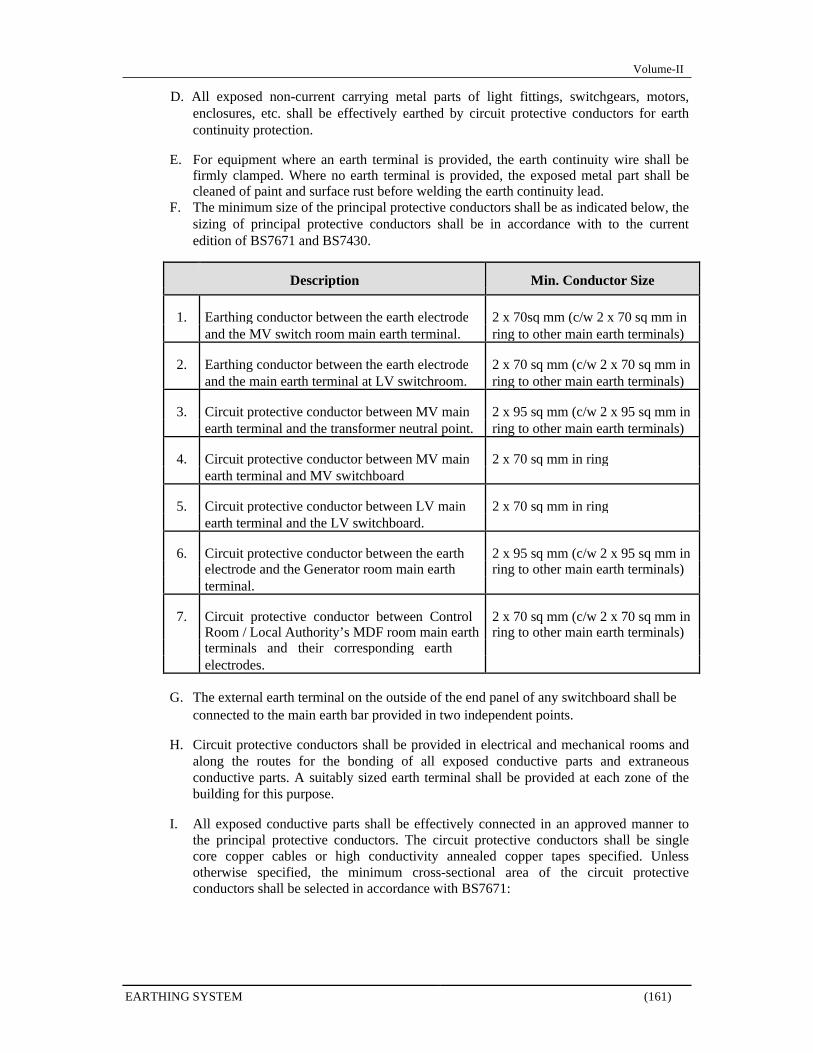
Volume-II
D. All exposed non-current carrying metal parts of light fittings, switchgears, motors, enclosures, etc. shall be effectively earthed by circuit protective conductors for earth continuity protection.
E. For equipment where an earth terminal is provided, the earth continuity wire shall be
firmly clamped. Where no earth terminal is provided, the exposed metal part shall be cleaned of paint and surface rust before welding the earth continuity lead.
F. The minimum size of the principal protective conductors shall be as indicated below, the sizing of principal protective conductors shall be in accordance with to the current edition of BS7671 and BS7430.
Description Min. Conductor Size
1. Earthing conductor between the earth electrode 2 x 70sq mm (c/w 2 x 70 sq mm in and the MV switch room main earth terminal. ring to other main earth terminals)
2. Earthing conductor between the earth electrode 2 x 70 sq mm (c/w 2 x 70 sq mm in and the main earth terminal at LV switchroom. ring to other main earth terminals)
3. Circuit protective conductor between MV main 2 x 95 sq mm (c/w 2 x 95 sq mm in earth terminal and the transformer neutral point. ring to other main earth terminals)
4. Circuit protective conductor between MV main 2 x 70 sq mm in ring earth terminal and MV switchboard
5. Circuit protective conductor between LV main 2 x 70 sq mm in ring earth terminal and the LV switchboard.
6. Circuit protective conductor between the earth 2 x 95 sq mm (c/w 2 x 95 sq mm in electrode and the Generator room main earth ring to other main earth terminals) terminal.
7. Circuit protective conductor between Control 2 x 70 sq mm (c/w 2 x 70 sq mm in Room / Local Authority’s MDF room main earth ring to other main earth terminals) terminals and their corresponding earth electrodes.
G. The external earth terminal on the outside of the end panel of any switchboard shall be
connected to the main earth bar provided in two independent points.
H. Circuit protective conductors shall be provided in electrical and mechanical rooms and along the routes for the bonding of all exposed conductive parts and extraneous conductive parts. A suitably sized earth terminal shall be provided at each zone of the building for this purpose.
I. All exposed conductive parts shall be effectively connected in an approved manner to
the principal protective conductors. The circuit protective conductors shall be single core copper cables or high conductivity annealed copper tapes specified. Unless otherwise specified, the minimum cross-sectional area of the circuit protective conductors shall be selected in accordance with BS7671:
EARTHING SYSTEM (161)
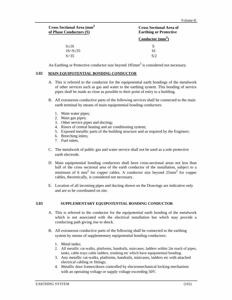
Volume-II
Cross Sectional Area (mm2 Cross Sectional Area of
of Phase Conductors (S) Earthing or Protective
S16
Conductor (mm2)
S
16<S35 16
S>35 S/2
An Earthing or Protective conductor size beyond 185mm2 is considered not necessary.
3.02 MAIN EQUIPOTENTIAL BONDING CONDUCTOR
A. This is referred to the conductor for the equipotential earth bondings of the metalwork of other services such as gas and water to the earthing system. This bonding of service pipes shall be made as close as possible to their point of entry to a building.
B. All extraneous conductive parts of the following services shall be connected to the main
earth terminal by means of main equipotential bonding conductors:
1. Main water pipes; 2. Main gas pipes; 3. Other service pipes and ducting; 4. Risers of central heating and air conditioning system; 5. Exposed metallic parts of the building structure and as required by the Engineer; 6. Breeching inlets; 7. Fuel inlets.
C. The metalwork of public gas and water service shall not be used as a sole protective
earth electrode.
D. Main equipotential bonding conductors shall have cross-sectional areas not less than half of the cross sectional area of the earth conductor of the installation, subject to a minimum of 6 mm2 for copper cables. A conductor size beyond 25mm2 for copper cables, theoretically, is considered not necessary.
E. Location of all incoming pipes and ducting shown on the Drawings are indicative only
and are to be coordinated on site.
3.03 SUPPLEMENTARY EQUIPOTENTIAL BONDING CONDUCTOR
A. This is referred to the conductor for the equipotential earth bonding of the metalwork which is not associated with the electrical installation but which may provide a conducting path giving rise to shock.
B. All extraneous conductive parts of the following shall be connected to the earthing
system by means of supplementary equipotential bonding conductors:
1. Metal tanks; 2. All metallic cat-walks, platforms, handrails, staircases, ladders within 2m reach of pipes,
tanks, cable trays cable ladders, trunking etc which have equipotential bonding. 3. Any metallic cat-walks, platforms, handrails, staircases, ladders etc with attached
electrical cabling or fittings; 4. Metallic door frames/doors controlled by electromechanical locking mechanism
with an operating voltage or supply voltage exceeding 50V.
EARTHING SYSTEM (162)
Volume-II
5. Metallic support to electrically operated equipment without direct electrical contact with the equipment;
6. Electrically operated roller shutters; 7. Metallic wall cladding containing, or immediately adjacent to, electrical socket
outlet or other sources of electricity; 8. Raised floor system; 9. Electrical facilities in toilets and shower rooms; 10. Exposed metallic parts of building structure, including roof trusses. (if roof trusses
connect to lightning conductor earth, no further equipotential bonding is required).
C. The requirement does not apply in the following instances:
1. Steel reinforced concrete poles in which the steel reinforcement is not accessible; 2. Exposed conductor parts which owing to their reduced dimensions or their
disposition cannot gripped or cannot be contacted by a major surface of the human body, provided that connection of these parts to the protective conductor cannot readily be made or cannot be reliably maintained. This item applies to small isolated metal parts such as bolts, rivets, nameplates and cable clips. A major surface of the human body is considered to be 50mm x 50mm.
3. Fixing screws for non-metallic accessories provided that there is no appreciable risk of the screws coming into contact with live parts.
4. Short lengths of metal conduit for mechanical protection of cables having a non-metallic sheath.
D. Local supplementary bonding conductors shall be provided between simultaneously
accessible (i.e. within 2m) exposed conductive parts of equipment, between exposed conductive parts and simultaneously accessible extraneous conductive parts, and between simultaneously accessible extraneous conductive parts. The bonding conductors shall be single core copper cables with oversheath in green/yellow colour.
E. Supplementary bonding, conductors shall be sized in accordance with BS7671 which
can be summarized as follows:
1. For conductors connecting two exposed conductive parts, the conductor sizes shall not be less than the smaller protective conductor connected to the exposed conductive parts, subject to a minimum of 4 mm2 if the cables are not mechanically protected;
2. For conductors connecting exposed conductive parts to extraneous conductive parts, the conductor sizes shall not be less than half that of the protective conductor connected to the exposed conductor parts, subject to a minimum of 4 mm2 of the cables are not mechanically protected;
3. For conductors connecting two extraneous conductive parts, the conductor sizes
shall not be less than 4 mm2, or even 2.5 mm2 if mechanically protected, for copper conductors.
F. All equipment equipotential bondings in area other than plant rooms and within false
ceiling shall be concealed. Any remedial work required due to bad connection, open circuit, etc. shall be borne by the Contractor;
G. All earth conductors and earth terminals shall be manufactured to carry the maximum
short circuit current at the point of the installation.
EARTHING SYSTEM (163)

Volume-II
SECTION E 10
LIGHTNING PROTECTION SYSTEM
1.0 GENERAL
1.01 WORK DESCRIPTION
A. The work to be done under this section comprises the engineering, supply and installation necessary for the complete installation of the Lightning Protection System.
B. The Lightning Protection System shall be installed generally in accordance with BS EN
62305 and IEC 61024-1-2 and additional requirements of this specification. The system shall be of the Faraday-cage type and shall consist of air terminations, down conductors, joints and bonds, testing joints, earth terminations and earth electrodes. The general arrangement shall be as indicated on the Drawings.
C. The lightning protection system shall comprise:-
1. Air Terminations; 2. Down Conductors; 3. Joints and Bonds; 4. Test Links 5. Earth Terminations.
D. Lightning protection system employing minimum 50sqmm stranded bare copper conductor
as part of the down conductors shall be adopted as per Drawing specified. All requirements in the specification included down conductors shall be applied unless otherwise specified.
1.02 STANDARDS
A. Complete installation shall be engineering and constructed in accordance with the latest
revision of the following standards and the appropriate BS/IEC :
1. BS EN 62305 - Protection against Lightning 2. AS1768 - Lightning Protection 3. BS7671 - Requirements for Electrical Installation 4. IEC 61024-1-2 - Protection of Structures against Lightning
B. The detail of the lightning protection system shall also conform to the requirements of all
relevant local codes, as applicable, together with the additional requirements referred to in this Specification and Drawings, whichever is the more stringent and acceptable to the Engineer.
C. In the adoption of standards and requirements, the Contractor shall take the following
precedence:
1. Engineer’s decision; 2. Local codes of practice; 3. Drawings; 4. Specification; 5. International standards and requirements.
LIGHTNING PROTECTION SYSTEM (164)
Volume-II
1.03 SUBMISSION
A. All technical submissions shall be approved by the Engineer prior to the respective stages of construction.
B. As a minimum requirement, the submission shall include the following:
1. Equipment submission with manufacturer’s data; 2. Sample submission; 3. Shop Drawings showing the co-ordinate routing of air terminations, down conductors
bonding to re-bar and foundation earth terminations, methods of fixing etc. 4. Builder’s works requirement. 5. Proposal on testing procedures and report format for testing of the Lightning Protection
System. 6. Detail of the Contractor’s installation Professional Engineer who supervise and endorse
the installation for occupation permit application.
2.0 PRODUCT
2.01 AIR TERMINATION
A. The Contractor shall supply and install an air termination system consisting of continuous horizontal conductors.
B. The conductors shall comprise of minimum 50sqmm Stranded Bare Copper unless
otherwise specified, located as shown on the Drawings and securely fixed in place to the building structure. Wherever possible, the horizontal conductors shall be continuous lengths.
C. Where saddled to masonry, the fixing screws shall be set in expansion type plugs contained
in properly formed holes.
D. All roof conductors are to be secured at intervals not exceeding 900mm.
E. The Drawings showing the various roof levels of the building indicate the general arrangement and layout of the air termination system. The Contractor shall ensure that the whole of the air termination system is installed over its total route of the roof areas maintaining absolute electrical continuity.
F. Provision shall be made with suitable fittings to allow for expansion and contraction of the
horizontal conductors.
G. 600mm height vertical copper air terminal shall be provided for the Air Termination network fixing next to masonry material at the highest points and any connection to down conductor.
H. Air termination on the vertical side of the building above 45m as required by code shall be
provided with maximum 30m spacing and minimum 2 points. The Contractor shall co-ordinate the installation detail to allow for bonding of the curtain wall to the embedded down-conductor re-bar to Engineer satisfaction and comply with BS code requirement. All additional materials and installation as required shall be included in the Contract.
2.02 DOWN CONDUCTOR
A. The down conductor routes shall be embedded in column as indicate on drawing and shall
be as direct as possible. B. The bonding conductor at roof conductor shall be of soft annealed copper strip minimum size
25mm x 3mm or 50 sqmm Cu cable. Where the conductors penetrate the roof, the holes shall
LIGHTNING PROTECTION SYSTEM (165)
Volume-II
be effectively sealed and waterproof with proprietary sealant to the approval of the specialist roofing contractor.
C. All exposed metal running vertically external to the structure shall be bonded to the 50sqmm
Stranded Bare Copper down conductor. This shall be included but not limited to curtain wall frame, pipes, ducts and other metal components running through the Buildings.
D. The down conductors shall be run according to the route as shown in the Drawings or as
required to BS code requirement.
E. The Sub-Conductor shall ensure that the proper material and equipment are used in accordance with the manufacture’s recommended installation.
F. Lightning protection system shall employing 50sqmm Stranded Bare Copper as down
conductor as per Drawing if specified.
2.03 JOINTS AND BONDS
A. Stainless steel connection plates shall be provided for termination of exposed copper conductors to steel rebar down conductors concealed in structure. All joints and bonds shall be soundly secured and shall be of low resistance. The cross- sectional area of the material used e.g. Copper shall not be less than the main conductor (i.e. 25mm x 3mm) unless otherwise specified.
B. Where possible, joints shall be kept as few as possible. All joints shall be carried out with
manufacturer’s recommended compress type clamp. Two (2) screw minimum shall be provided for each joint.
C. Bonding Points shall be carried out with manufacturer’s recommended sets. Customer’s
self-made items are not acceptable.
D. Joining of dissimilar metals shall be protected from moisture by applying recommended compound on the material. Bi-metal joint shall be provided where dissimilar metals are used.
E. All junction and bonding clamps shall be brass/phosphor bronze material.
2.04 EARTH TERMINATION
A. Down Conductor will be bonded to ring conductor installed in buildings’ foundation raft
after Copper Test Link by 50sqmm Stranded Bare Copper Conductor at the ground level along the perimeter of the building to comply with IEC 61024-1-2.
B. The maximum permissible earth resistance of the Lightning Protection System shall be 10
ohms. Testing earth electrode shall be provided for earthing test.
3.0 EXECUTION
3.01 METALLIC CURTAIN WALL BONDING
A. All elements of the façade shall be directly earthed to the structure for the purpose of lightning protection. The Contractor shall make himself aware of the requirements under the latest revision of BS latest code and IEC 61024-1-2. All necessary connections, conductors, earthing connectors etc shall be deemed to be included in this Contract.
B. The Contractor shall co-ordinate with the Curtain Wall Supplier/Contractor for the exact
interface and bonding requirements. The curtain wall is to be electrically continuous and the LIGHTNING PROTECTION SYSTEM (166)

Volume-II
installation shall comply with BS EN 62305. Tests shall be carried out by this Contractor to the satisfaction of the Engineer to ensure electrical continuity as stipulated in the code.
C. Lightning protection bonding terminals along re-bar down conductor shall be provided by
the Contractor at the lowest levels and roof levels for bonding with curtain walls. Intermediate bonding terminals shall be provided at an interval of not exceeding 30m apart at each of the vertical intervals of each down conductor.
D. As a general practice, bonding points shall be provided and located on the internal face of
the claddings. A conductor shall be provided and installed by the Contractor for lightning protection bonding at the down conductors.
E. The Curtain Wall Supplier/Contractor shall be required to confirm his details on the
lightning protection bonding of curtain walls. It is the responsibility of this Contractor to ensure all details (both locations and quantity) agreed complied with BS latest code.
F. All metal cladding components including panels, glazing frames, mullions, transoms, fixings
and support structures shall be fully bonded electrically to ensure electrical continuity of the building development.
3.02 EQUIPMENT/STRUCTURE BONDING ON ROOF & OTHER EXTERNA L AREA
A. The Contractor shall be responsible for bonding of all metal equipment/structure on roof and
other exposed external area on flat roof and ground level, complete cabling by means of 25 x 3mm copper tape or 50sqmm Cu cable up to the termination point provided by respective Contractor. Bonding within the equipment for maintaining electrical continuity of all metal components will be provided by the respective work in the Contract.
B. All metallic projections, chimneys, vent pipes, cooling towers, railings, antenna masts, fuel
tanks, etc. on or above the main surface of the roof and other external areas shall be bonded to and form the part of the air termination network.
C. For equipment with plan area above 100sq.m, bonding shall be provided at distance not
more than 30m apart equally spaced along the perimeter of the equipment.
D. All bonding shall be to the nearest down conductor by most direct route available.
4.0 TESTING & COMMISSIONING
A. The Contractor shall arrange with the Engineer for inspection and testing of lightning conductor system. Before the joint testing, the Contractor shall have conducted his own inspection and testing to ensure that all requirements are met as specified. Test report certified by Contractor’s installation Professional Engineer shall be submitted to the Engineer. All equipment, transportation, manpower and other necessary costs for the joint inspection and testing shall be borne by the Contractor.
B. The system shall also be tested at not greater than twelve (12) months intervals for earth
resistivity, resistance to earth of the electrodes and electrical continuity of the system during the course of building construction and DLP. The results of these tests shall be by the Contractor’s installation Professional Engineer compiled in report prepared by the Contractor.
C. The Contractor shall supply facilities for the recording of the test results referred to above,
arranged in such a manner that comparisons can be readily made with earlier readings.
LIGHTNING PROTECTION SYSTEM (167)
Volume-II
D. The Contractor shall submit a detailed layout drawing showing the positions of testing carry out on site.
E. The record sheet and layout drawing shall be kept on site at all times during the course of
construction.
F. The Contractor shall carry out monthly inspection on the lightning protection system including the earthing pits to ensure that the system is in good working order.
LIGHTNING PROTECTION SYSTEM (168)

Volume-II
SECTION E 11
TESTING, COMMISSIONING, INSPECTIONS AND CERTIFICATI ONS
1.0 GENERAL
1.01 WORK INCLUDED
A. General - The Contractor shall completely test and inspect all systems in accordance with the specifications and drawings. The Contractor shall certify that all systems are in complete working order prior to turning over to the Employer.
B. At least 30 days prior to testing or commissioning any system, the Contractor shall
furnish the following information for each system to process to the Engineer for review.
1. Testing procedure and details as well as the relevant report forms to the Engineer for approval.
2. Type of instruments to be used. 3. Manufacturer of instruments 4. Calibration methods for instruments 5. Operating instructions for instruments 6. Accuracy and tolerances of instruments
C. Submit, within 90 days from the commencement of the Contract a detailed and
comprehensive installation completion/start-up/testing schedule, identifying all work and suppliers to be involved. Update the schedule and resubmit for review, on a monthly basis, during the course of commissioning. If found to be unacceptable, revise the schedule and the construction forces to suit the reviewed scheduled.
D. The Contractor shall employ a team of competent and experienced personnel to carry out
all testing and commissioning works. If it is the opinion of the Engineer that the testing and commissioning are not properly executed by the Contractor’s own staff, the Contractor shall employ a qualified independent Testing and Commissioning Specialist to carry out this part of the Works, when directed by the Engineer. The cost of employing this Testing and Commissioning Specialist shall be borne by the Contractor. Supply the following details regarding the proposed firm for approval:
1. Principle representative and qualifications 2. Proposed personal and relevant project experience 3. Previous similar assignments and references 4. Scope of work to be undertaken 5. Company resources and equipment
E. All equipment site testing and commissioning shall be carried out by manufacturer’s
qualified personnel as required.
F. All test shall be witnessed by Engineer.
G. All tests specified in this specification and BOQ are minimum requirement. Test specified in all other section shall be included in the Contract. The Engineer may request and include any test as required without time and cost implication.
H. Draft of manuals shall be submitted for Engineer review in advance of testing to allow the
Engineer to familiarise with the equipment manufacturer’s recommendation. Final draft
TESTING, COMMISSIONING, INSPECTIONS AND CERTIFICATIONS (169)
Volume-II
manuals must be submitted for the Engineer’s review before Taking Over Certificate is prepared.
1.02 CO-ORDINATION
A. Meet the requirements of the General Instructions
B. Co-ordinate the work of this Section with all other Divisions to ensure complete and
operational mechanical systems at completion of this work.
C. Appoint a single person as Commissioning Coordinator who shall be responsible for progressing the commissioning activities for all work in the Contract.
D. Review the intent of the project and the intended operation of systems with the Engineer
before proceeding with commissioning.
1.03 GENERAL TESTING
A. It shall be the responsibility of this Contractor to furnish all testing equipment and labor necessary to perform the following test:
1. After wires or cables are in place, but before being connected to devices and
equipment, the system shall be tested for shorts, opens, intentional and unintentional grounds by means of wires in conduit that are shorted or unintentionally grounded shall be replaced.
2. A voltage test on the last outlet of the branch circuits shall be spot checked or as
directed by the Engineer and the potential drop shall not exceed 2%. Voltage drops for panel and large feeders shall not exceed 3% hence the total voltage drop for a feeder and any branch circuit shall not exceed 5% of the service voltage. The test shall be made under specify load or its equal.
3. Any wiring device, or electrical apparatus in this contract, if grounded or shorted on
an integral "line" part, shall be removed and the trouble corrected.
4. When required, complete test and inspection records shall be made and incorporated into a report for each piece of equipment tested. All readings taken shall be recorded. Four (4) copies shall be submitted to the Engineer for approval.
2.0 PRODUCTS
2.01 TEST EQUIPMENT AND MATERIALS
A. The Contractor shall provide all testing instruments, equipment and all materials, connections etc. required to perform tests in accordance with these specifications.
3.0 EXECUTION
3.01 WIRING TEST
A. All wiring and cable tests shall be made before any circuits, main switch, motor, transformer or line is energized.
TESTING, COMMISSIONING, INSPECTIONS AND CERTIFICATIONS (170)
Volume-II
B. Tests shall be made for continuity, identification and absence of shorts and grounds for each conductor. Both ends of a given conductor shall be identified alike. Before circuit terminal connections are made, continuity and identification of wiring shall be checked by means of a DC test device using a bell, light, meter, or buzzer.
C. Insulation test shall be make at the following values:
D. 230 Volt Wiring at 500 Volts DC
E. Insulation resistance between phase conductors and ground shall not be less than the
minimum requirements of 200 mega-ohms. 1. Wire terminations are not to be made to equipment (motors, MCCs, bus ducts, etc.),
until that piece of equipment has been tested and verified as specified in this sections.
2. Test motor feeders with motors disconnected, but with circuit breakers, switches or starters in the circuit opened so as to include only that portion of the feeder it is desired to test.
3. Test lighting feeders with the circuit breakers and panelboards connected but with
lighting branch circuit breakers or switches open so as to include only the feeder circuit desired to test.
F. Contractor shall correct or replace any circuit which is defective or grounded and he shall
also correct all other troubles encountered by these tests. All defects whether due to faulty workmanship or material furnished by the Contractor shall be corrected under this section at the Contractor's expense in a manner acceptable to the Engineer.
3.02 LIGHTING TEST
A. Check all lighting fixtures for proper operation. All Contractor supplied fixtures to be
100% operable at no additional cost to the Contract.
3.03 MOTOR TEST
A. All 400 volt motors shall be individually tested for insulation resistance using 1000V DC. All 230V motors shall be tested with 500V DC in a similar manner. The minimum resistance to ground shall be 2000 mega-ohm (corrected to 50 degrees C). The Contractor shall record the ambient temperature of the motor and submit this value along with insulation resistance value. For motors from 7 1/2 to 20 HP, Contractor shall submit Dielectric Absorption Ratios. For motors above 20 HP, the Polarization Indexes of the motor shall also be submitted.
B. Make the following checks on all motors prior to start -up:
1. Check motor name plates for H.P., speed, phases and voltage. Verify proper wiring.
2. Check shaft for freedom of rotation.
3. Verify that the motor is properly lubricated prior to energizing.
a. Contractor to furnish a proper sized heater for each overload relay. Notify the Engineer prior to installation of the motor full-load current rating, the number of overload relays, the starter catalog number, and the heater catalog number. The Engineer will aid in the selection of the proper heaters if requested, provided all pertinent information is given.
b. Make the following tests on all motors during or immediately after start-up:
TESTING, COMMISSIONING, INSPECTIONS AND CERTIFICATIONS (171)
Volume-II
1) Check for proper shaft rotation. 2) Check motor for smooth operation (vibration). 3) Take a current reading using a clamp-on ammeter. (No-load readings and
loaded readings).
3.04 PANELBOARD, BUS DUCT AND M.C.C TESTS
A. Test all equipment to be operated on the 230V system at 500V DC prior to connecting feeders. A minimum insulation resistance of 200 mega-ohm shall be obtained between all phases and between phase and ground.
3.05 TRANSFORMER (POWER 600V OR LESS) TEST
A. Insulation tests on transformers shall be as follows:
1. 230Volts Low Side
a. Test with 500V DC, low side to ground. 200 mega-ohm shall be the minimum acceptable insulation resistance.
3.06 INSULATION TEST
A. Insulation test mentioned in this section shall be interpreted as the specific test method of
obtaining insulation resistance by applying indicated test voltage for 60 seconds to the equipment or wiring being tested.
3.07 FACTORY TEST
The following items of equipment shall be tested at the manufacturer’s works or elsewhere as appropriate prior to installation. In all cases, test certificates shall be submitted in triplicate certify by the Contractor’s Engineer.
A. LV Switchboard and Motor Control Centre 1. Type test Certificates indicate short circuit capacity and temperature rise 2. Factory Tests Report on the
unit. B. Generating Plant
1. Type Test Certificate 2. Factory Tests Report on the unit
C. Fuel Storage Tank 1. Hydraulic Test Report endorsed by Contractor and manufacturer
D. MV Switch Board 1. Type Test Certificate 2. Factory Tests Report on the unit.
E. MV/LV Transformer 1. Type Test Certificate 2. Factory Tests Report on the unit
F. The Contractor shall include for the requirement for witness at manufacturer Factory
Test, the Engineer and Employer representative – 2 persons 3 working days (excluding transport time) for tests at USA embassy/Local agreed rate.
TESTING, COMMISSIONING, INSPECTIONS AND CERTIFICATIONS (172)

Volume-II
3.08 EXECUTION OF SITE TESTING AND COMMISSIONING
A. The plant shall be inspected and tested during and after installation on site as set out below for compliance with the performances, and ratings as specified.
B. All tests shall be witnessed by the Engineer’s representative at site with at least seven
days' notice given prior to any test.
C. All tests shall be executed and, if not satisfactory, repeated to the satisfaction of the Engineer at no extra cost.
D. Partial Discharge and Ultrasound testing for Medium Voltage Equipment to locate any
high dB readings or any partial discharge. The test shall be performed by specialist Tester completed with conclusive report to record the working condition of the installation and termination.
E. Infrared Thermoelectric Detection to all MV and LV Main Switch Board, Transformer,
Generator and Busduct to locate any hot spot or loose termination. The test shall be performed by specialist Tester completed with conclusive report to record the working condition of the installation and Termination.
F. At the appropriate stages of the installation, inspection and testing prior to the energizing
of equipment, insulation tests shall be made and recorded
G. Operational tests of all electrical equipment in proper staged phases shall be made and recorded prior to energizing. For example, the battery charger and batteries shall be checked prior to furnishing the DC control power for the circuit breakers. The circuit breaker control shall be operationally checked for all local control, including testing up to interface terminal points for signals and control interconnection to other system or installation, prior to carrying out operational tests of the circuit breaker.
H. The Contractor shall develop a complete and detailed plan for the site testing of the power
supply systems beginning with the incoming breakers and following a logical plan which will allow energization of the system in a safe and secure manner and to interface and co-ordinate with the other electrical and mechanical installations.
1. The Contractor shall provide his own equipment for testing and check the installation
to ensure that it complies with drawing and specification and Local Authority’s requirements, including the preliminary polarity test and phasing of electrical mains.
2. Test results shall be recorded and certified by Contractor’s qualify personnel. Two (2)
copies of such report shall be submitted to the Engineer prior to the joint testing.
I. The Contractor shall be responsible for the surveillance and security of the power systems including padlocking or otherwise maintaining control of the power supply, padlocking of switchgear and circuit breaker units, distribution switchboards, etc. throughout all energization stages of the installation. The Contractor shall co-ordinate with all work to assure no downstream cables or other electrical equipment is energized before tested and before facilities which receive power are ready and secure. The Contractor’s responsibility for surveillance and security of the system shall remain in force for each part of the system until such a time that the complete installation is certified complete by the Contractor in writing.
J. Precautionary measures shall be taken during testing and the method of tests shall be such
that no danger to persons or property can occur even if the circuit being tested is defective.
TESTING, COMMISSIONING, INSPECTIONS AND CERTIFICATIONS (173)
Volume-II
3.09 SITE TESTS
A. All equipment, cabling, distribution, etc. is electrically and mechanically safe
B. All interlocks, isolators and door cover securing mechanisms are properly fitted and adjusted
C. All exposed metal work is properly bonded and earthed in accordance with IEE regulation and statutory requirements and that all connections and points required to be earthed for safety and satisfactory operation are properly earthed in accordance with the manufacturer’s requirements
D. All cables, cores and terminations are properly marked off, secure, properly supported and
correctly identified and coloured
E. All phases, polarities, natural and common connections are correctly switched as required, that power is correctly available at all points and that voltage and frequency at all equipment are correct and in accordance with requirements for correct working.
F. All supplies are properly fused, or otherwise protected to give satisfactory discrimination
and safe disconnection under fault conditions
G. All contract are properly aligned and not subject to excessive wear and erosion
H. All protective covers are properly fitted, all warning and designating labels are correct and in position and the inside of all boxes and cubicles are clean and free of “swarf” and cable strippings
I. Batteries, if provided, are properly ventilated, installed, connected and fitted, and that
battery chargers are working correctly
J. Insulation resistance of all cabling and equipment is not less than that required by relevant Electrical Installation code.
K. All instruments and meters are energized with correct polarity and working properly
L. All fault indications and alarms are working correctly and
M. All essential equipment fed from battery systems continue to function correctly and
without disturbance during all supply failure, restoration and standby sequences.
N. In addition to all operational tests required for satisfactory completion, the operation of all interlocks, sequences and protection not utilized in normal operations shall be checked to the satisfaction of the Engineer.
3.10 FUNCTIONAL TESTS
Functional test for the system shall be conducted for performance, safety, reliability, maintainability and for compliance with the specified requirements. These tests shall be performed progressively on site in accordance with the Contract programme to verify that the complete installation will meet the requirement of this specification. The list provided below is an indicative minimum of the tests required. The Contractor shall develop full test schedules for approval in accordance with the requirements as spelt out in respective sections of the Specification.
TESTING, COMMISSIONING, INSPECTIONS AND CERTIFICATIONS (174)

Volume-II
A. General
1. Check correct CT ratio and polarity and correct operation of all protective gear by primary tests and system fault tests to check sensitivity and stability
2. Secondary current injection tests for accuracy of relay operations. Protective gear timing tests as may be necessary
3. Rotational tests on all motors 4. Battery tests on specific gravity, correct output voltage, discharge test and proper
functioning of the charging equipment etc. 5. Tests to prove correct operation of all interlocks, tripping and closing circuits, alarm
indications, etc. including operation in conjunction with the standby generator for emergency operation of lofts, etc.
6. Phasing tests.
B. MV Switch Board, Transformer, and MV cable
1. Injection Test (Primary ad Secondary) 2. Insulation Test 3. Partial Discharge and Ultrasound Test 4. Infrared Thermoelectric Detection 5. Manufacturer Recommended Test
C. LV Switchboard
1. Mechanical tests 2. Continuity and dielectric tests 3. Secondary injection test to re-calibrate all measuring, protect and control circuits and
associated components 4. Phase sequence tests on each outgoing units 5. Functional checks, especially on the controlling devices and 6. Infrared Thermoelectric Detection (include power factor correction equipment) 7. Primary Injection Test
D. Cables
1. Continuity test 2. Insulation resistance test and 3. Phasing test
E. Standby Generating Plant
1. Series of test starts and checks on ability to take up the load within the specified time 2. Check that speed variation is within specified limits 3. Voltage regulation test 4. Functional tests of all plant protection features and alarms 5. Temperature rise test 6. Noise level measurement 7. Insulation resistance test 8. Building essential load test and 9. Infrared Thermoelectric Detection.
F. Hydraulic Tests
1. Hydraulic test of 70 kPa for bulk tank for not less than 2 hours 2. Hydraulic test of 70 kPa for pipeworks, valves and fittings for not less than 2 hours.
TESTING, COMMISSIONING, INSPECTIONS AND CERTIFICATIONS (175)
Volume-II
G. LV Power Distribution System The following items, where relevant, shall be tested in the sequence indicated:
1. Continuity of ring final circuit conductors 2. Continuity of protective conductors, including main and supplementary equipment bonding 3. Earth electrode resistance 4. Insulation resistance 5. Insulation of site-built assemblies 6. Protection by electrical separation 7. Polarity 8. Earth fault loop impedance 9. Function of all items of equipment and 10. Infrared Thermoelectric Detection
H. Lighting
1. Illuminance / luminance measurements for normal, emergency and battery lightings 2. Illuminance / luminance measurement for battery lights at the end of 2-hour operation 3. Test to establish correct operation of switching control 4. Insulation resistance tests to earth and between conductors before and after fitting of lamps 5. Measurement of leakage current when directed by the Contractor.
I. Lightning Protection System 1. Continuity between air and Foundation earth; and 2. Foundation Earthing
J. UPS
1. Full Test to Manufacturer Recommended Procedures 2. Full load test to verify the total back-up time 3. Infrared Thermoelectric Detection; and 4. Ultrasound Test
K. Extra Low Voltage System
1. Full Functional Test to Manufacturer Recommended Procedure
3.11 AUTHORITIES TEST AND INSPECTION
A. The Contractor shall engage sufficient qualified and experienced site staff to execute the works. Qualify personnel shall be employed to supervise the works if necessary.
B. The services of Professional qualify personnel (Mechanical and Electrical) and other statutory licensed workers shall be engaged to assume full responsibilities for all engineeringmatters including engineering, submission to Authorities, installation and switching. Thesepersonnel shall be available to attend meetings, discussions, inspections, and the like asrequired by the Engineer and Authorities. Upon completion of the Contract works, the qualify
personnel of the Contractor shall furnish Completion and Inspection Certificates with
the same format as required by the respective authority for the respective parts of the works to the Engineer to certify that all the works are in full compliance with the Specification and Drawings.

TESTING, COMMISSIONING, INSPECTIONS AND CERTIFICATIONS (176)
Volume-II
3.12 FINAL ADJUSTMENTS AND COMMISSIONING
A. When the entire installation works are completed and all the above checking and testing have been properly carried out, the Contractor shall set to work, regulate and calibrate the entire installation. Particular attention shall be paid to the following:
1. All equipment are silent and meeting the specified noise and vibration levels.
2. All instruments are correctly calibrated and read accurately.
3. All control systems are functioning correctly and are properly sequenced, interlocked,
and interfaced with other services.
4. All major plant to be fully commissioned by the respective Manufacturer’s qualified field testing and commissioning engineers.
5. The Contractor shall be aware that the commissioning may need to be carried out after
the Taking Over Certificate is issued and after normally office hours, as required by the Employer.
3.13 TAKING OVER
A. The following procedures shall be adopted prior to taking over the installation:
1. All preliminary testing, checking, adjusting and balancing of the installation shall be carried out before forwarding notification that the installation is considered to have reached Practical Completion.
2. After inspection, and when the Engineers is satisfied and agrees that the installation is
ready for taking over to the Employer, the plant shall be finally commissioned and Installation Manuals together with as-built drawings shall be provided as specified.
3.14 POST COMPLETION PERFORMANCE VISITS
A. Visit the site with the Employer’s representative each month after project completion for a
minimum period of two days until the end of the project warranty period.
B. Review the operation of the system.
C. Correct any operating problems, if problem is related to warranty issues.
D. Prepare re report for inclusion in the Operating Manuals of the problems and issues that have arisen and the corrective action(s) recommended and implemented.
TESTING, COMMISSIONING, INSPECTIONS AND CERTIFICATIONS (177)
Volume-II
SECTION E12 PARTICULAR SPECIFICATIONS
CLIMATIC CONDITIONS
The Contractor/Constructor is deemed to be familiar with climatic conditions prevailing in Peshawar and to be aware of the high temperature up to 50°C, max. The Contractor/Constructor in submitting a tender will be assumed to warrant that all materials and items of equipment are suitable for continued use and/or operation in the various climatic conditions encountered.
STANDARD AND STATUTORY REGULATIONS
The works shall be carried by a registered Contractor/Constructor approved by the relevant authority for each particular classification of work. All material and workmanship shall conform to the specifications and to the following:
REGULATION
Not with standing anything to the contrary contained herein pertaining to this installation, it shall be the Contractor’s/Constructor’s responsibility to ensure that all the works are in strict accordance with the following statutory obligations, regulations and specifications together with any amendments made thereto:
a) British Standards Institution or other approved international standards. b) 17th Edition of the UK I.E.E. Wiring Regulation. c) Building Control Act and Regulations d) Building Energy Code of Pakistan e) Electrical Act, 1910 f) Electrical Rules,1937 g) Any other local authority having jurisdiction
SCOPE OF WORK
The work shall include furnishing all materials, labors, plant and supporting services for
complete supply, installation, testing and commissioning of the following:
a. Primary underground service line as required for the project. b. Distribution equipment including LT Cabling, Motor Control Unit Panel (MCU) and
Distribution Boards. c. A system of interior lighting and power wiring including feeders, circuits, sub-circuits and
point wiring. d. A system of interior Luminaries for common areas. e. Switches and small power sockets. f. Earthing System. g. PVC pipes, cable ducts and other raceway for power system. h. Complete testing and commissioning of the Entire Electrical System installation.
PARTICULAR SPECIFICATIONS (178)

Volume-II
SAMPLES
The Contractor/Constructor shall arrange and submit for approval one set of labeled samples as
follows:
Conduits/Pipes, fittings and supports. Wires and cables Switches and sockets Light fixtures MCU shall be inspected by Engineer prior to delivery at site
The Consultant (Engineer reserved the right to require samples which show the fabrication techniques and workmanship of component parts, and the design of accessories and other auxiliary items, before any installation work proceeds. The Contractor’s/Constructor’s shall submit to the Consultant/Engineer for endorsement
manufacturer's specification and installation instruction for trade products.
SHOP & AS-BUILT DRAWINGS
The Contractor/Constructor shall submit for the Consultant/ Engineer's approval 02 sets of shop drawings in a timely manner according to the construction Program. Within 14 days of being notified of the intent to award the contract, the contractor shell submits the submission program for approval. The submission program shall include the following details:
List of shop Drawings Proposed submission dates Proposed approved date to meet the installation and Authorities submissions program.
The shop drawings must be or sufficient detail to satisfy the installation requirements to the approval of
the Consultant/Engineer. The shop drawings shall show all location of equipment, cable trucking/tray
routing, conduits, and joints for wiring, anchors, supports, hangers, test points, measurement instruments,
and the like. As built drawings shall be similarly submitted at Completion.
On completion of work contractor/constructor will prepare As-built drawings for all works including every electrical items/system and would submit at least 04 sets of drawings in hard copy form and one CD for soft document.
PARTICULAR SPECIFICATIONS (179)
Volume-II
CABLE SUPPORT SYSTEM
Cable Support System
Steel Conduit:
Conduits shall be of heavy gauge steel conforming to British Standard. They shall be solid drawn or
seamed by welding. Both ends of the conduit shall be screwed. Conduits shall be galvanized to Class 4
type of BS 4568:1970 and be of approved reputable manufacture. Adequate protection against corrosion
shall be applied to both conduit interior and exterior. Flexible conduits shall be of mild steel complying
with BS 731: Part 1:1952. Where the situation requires, they shall be PVC covered.
Fittings:
Fittings shall be those intended for use with screwed conduits and shall comply with BS 4568: Part
2:1970. However, bends, elbows and tees shall not be installed. Adopters used with flexible conduits
shall conform to BS 731: Part 1:1952.
Circular Boxes:
Circular boxes shall be of malleable cast iron, galvanized and of standard pattern with spout(s),
cover plates of similar make complete with brass fixing screws.
Rectangular Boxes:
Rectangular boxes (adaptable boxes) shall be of mild steel not less than 2.0 mm gauge and
galvanized, with lids of the same gauge with brass fixing screws.
Boxes for Accessories:
Boxes for accessories shall be suitable for surface mounting or recessed mounting. Surface mounted
boxes and accessories shall be of metal clad pattern. Recessed boxes and accessories shall be
complete with insulated molded type cover plates.
PVC/PVC Conduit:
Conduits shall conform to BS 6099: Part t and shall be heavy gauge of wall thickness of 1.9 mm rigid
tubes which are unscrewed without coupling and with plain ends. All conduits used shall not be less
PARTICULAR SPECIFICATIONS (180)

Volume-II
than 25 mm in diameter. PVC conduit mounted outside building will not be accepted. PVC conduits
shall not be used where liable to mechanical damage.
PVC/PVC Conduit Accessories:
Accessories used for conduit wiring shall be of an approved type complying with BS 4607. Plain
conduits should be joined by slip type of couplers with manufacturer's standard sealing cement.
PVC-switch and socket boxes with round knockouts are to be used. The colors of these boxes and
the conduits shall be the same. Standard PVC circular junction boxes are to be used with conduits
for intersection. Tee-junction angle junction and terminal. For the drawing-in of cables, standard
circular through boxes shall be used.
All jointing of PVC conduits shall be by means of adhesive jointing. Adequate expansion joints
shall be allowed to take up the expansion of PVC conduits.
Cable Tray and Trunking:
Metal trucking shall comply with BS 4678 and shall be manufactured in minimum lengths of 2m
from 16 SWG GI sheet. Covers are to be held in place by screws. Conduit entries to trucking shall
be made with couplings and brass male bushes. Turnings shall not contain more cable than allowed
by the space factors described in the IEE Regulations.
All supports and hangers shall be of hot-dipped galvanized mild steel construction to BS 729:1971
Part 1 with min. coating thickness of 85 and 210 for indoor and outdoor installation respectively. All
bolts and nuts shall be electroplated with zinc or cadmium to BS 3382: Parts 1 and 2 with min.
plating thickness of 25.
Cable tray shall be of perforated type and constructed of minimum 1.6 mm hot dipped galvanized
mild steel. Cable trays shall be supported by electro-galvanized ‘U’ channel with galvanized
threaded rod for indoor suspended tray and hot dipped galvanized for area subject to weather.
Cable trucking shall be manufactured from 1.6 mm minimum electro-galvanized sheet steel to BS
1449: Part 1:1983 finished in oven-baked electro-statically coated epoxy powder coating Cable
trucking, subject to weather, shall conform to BS 729, hot dipped galvanized and painted. External
flanges shall be provided to avoid ingress of water.
Conduit Instillation:
The whole conduit system shall be installed to comply fully with IEE Wiring Regulation.
PARTICULAR SPECIFICATIONS (181)
Volume-II
1. PVC conduit Electrical Grades shall be used for concealed wiring.
2. PVC pipe class D/RCC pipe class A/GI pipe light grade for underground wiring.
3. Flexible PVC conduit with appropriate glands shall be used for termination of all
connections to recessed light fixtures in false ceiling.
4. Flexible steel conduit, to BS 731/6099, shall be used for final connection to motor and other
equipment subject to vibration and movement.
5. Under floor runs of conduits shall have at least 50 mm of concrete cover and be well sealed
against the ingress of moisture.
6. All accessories fittings and glands used for outdoor installation shall be corrosion proof and
weatherproof type.
7. Factory-made bends, joints, elbow; riser, tee, reducer and accessories with same material
shall be provided throughout the installation for tray and trucking.
8. Copper earth link bar shall be fixed at every joint of the cable tray and trucking run.
9. All hangers for cable trays/trucking shall be installed at 1 meter intervals.
PARTICULAR SPECIFICATIONS (182)

Volume-II
CABLE AND WIRING
Cables and Wiring
600/1000-Volt PVC, XLPE/PVC, PVC/PVC, XLPE/SWA/ PVC and PVC/SWA/PVC Cables
Cables shall utilize standard copper conductors only. All cables shall be made in accordance to the
following standard. BS 6346:1997 BS 7870-3.1:1996 BS 6004:1995. Insulation colors and wire
sizes shall be in accordance to IEE Regulations. PVC insulated, PVC sheathed copper conductor
cable for internal power distribution.
Circuit and sub-main wiring shall have an adequately sized earth continuity conductor. The
maximum continuity resistance from any point of the installation including the earth continuity to
the earth electrode shall not exceed one Ohm.
Wiring shall be continuous between terminations and use of connectors or joint will not be allowed
(joints in point to point cable runs are prohibited). Cables for 3 phase 4 wire system shall be colors
coded red, yellow, blue for phases, black for neutral and green/yellow for earth. For flexible cords
the minimum size shall be 1.5 sq. mm. Flexible cords connecting into lighting fittings shall be 3
core heat resistant Butyl' rubber insulated.
Wiring to light points, 5A, 13A & 15A Power Outlets:
450/750-volt grade PVC insulated/sheathed copper conductor cables single multi core shall be used
for circuit wiring of light points and sockets. Power wiring shall be kept separate and distinct from
lighting wiring. All wring must be done from distribution boards. A separate earth wire will run all
along the power wiring and will be properly earthed.
Terminations and Cable Glands:
Cables entry into the main or distribution switch boards, shall be through approved glands
adequately sized for all cables. All accessories, fittings and glands used for outdoor installation shall
be corrosion proof and weatherproof type to approval. Conductor connections and terminations shall
be made with compression ferrules and lugs to BS 91 using a hydraulic crimping tool. IP class of
cable glands should be same as DB/MCU
Installation methods:
Unless otherwise specified, all outdoor wiring shall be PVC/SWA/PVC for core single core cable
direct buried in the ground and heavy duty PVC or RCC pipes under driveway, pavement, hard core
area etc.
PARTICULAR SPECIFICATIONS (183)
Volume-II
ACCESSORIES
Accessories
Switch and Socket Outlet Boxes:
Gang outlet boxes shall be used where two or more devices are grouped in one location. These
outlet boxes shall be made of 1.63 mm. sheet steel with protective black enamel paint coating inside
and outside the box.
Before applying black enamel, the cleaned surface of sheet steel box shall be given lead oxide
antirust coating inside and outside the box. The cover of such outlet box shall be approved
amazonite, Teflon, Bakelite or plastic. Where switch and socket outlet boxes are to be installed on
surface in an exposed conduit wiring system, these shall have, in addition to the protective coating,
color paint coating to match the color of the walls etc.
Weatherproof enclosure shall be of the high impact water resistant to IP 65. The isolator provided
shall be complete with a lockable device.
Switches:
Switches controlling light and fan points shall be single pole. These shall be made of Bakelite or plastic
and suitable for flush mounting in an outlet box. Where more than one switch is to be installed at one
location, the switches are formed in gangs. Switches shall be rated at 10 amperes (Logic Grids), 250
Volt. Switches for external use shall be of weatherproof construction with IP 65 rating.
Switched Socket Outlets:
Only switched socket outlets shall be used Socket and plug unit shall be 3-pin 13 Amps universal for
power outlets at 250 Volts and 220/115 volt for shaver socket outlet These shall be made of Bakelite and
suitable for mounting flush with wall or column or for surface mounting as required. Where socket and
switch units are installed outdoor, or in a damp or wet area, they shall be IP65 rated.
Installation of Switches and Socket Outlets:
Switches and socket and plug units shall be installed flush in the wall. All switches shall be
installed at a height of 1.2m from finished floor level- Socket plug and switch units shall have its
centerline at 450mm above finished floor level.
PARTICULAR SPECIFICATIONS (184)

Volume-II
LIGHT FITTINGS AND FIXTURES
Fluorescent Light Fixture:
Fluorescent light fittings shall be supplied complete with the lamps and ballasts of required wattage.
The fluorescent tube shall be TL5 color 84 type, totally enclosed and suitable for 230 volts, 50Hz
single-phase supply. The wiring diagram along with the voltage, wattage and current values shall be
printed on the body of the ballast. The internal wiring of the fluorescent light fittings shall be
completed at the factory, with heat resistance wires having a minimum cross-sectional area of 1.5
sq. mm.
Lamp Holder:
The Lamp holders shall be bi-pin, spring loaded of robust construction and designed to retain
positively the lamp caps independently of the contact springs. Contact springs shall be of phosphor
bronze material.
Bracket Fans:
Fans, to BS 5060, shall be of the capacitor type, specially designed blades for quiet operation, wide
air throw, 3 speed adjustment, powder coated, Die cast aluminum body, low energy consumption,
works even on low voltage, double “Z” Ball Bearings, High Grade Copper Wire & Silicon Steel
Sheet, 3-StageUp and down Adjustment and remote control option.
PARTICULAR SPECIFICATIONS (185)
Volume-II
LOW VOLTAGE SWITCHGEAR
Motor Control Centre (MCC):
Motor Control Centre should be in compliance with BS 5486/4752, shall be of the cubicle type,
totally enclosed, dust-proof: floor/surface/flush-mounting type, fabricated from 14 gauge sheet
steel, derusted degreased, rust-proofed, painted with two coats of enamel, with hinged covers, and
metal safety plates. The equipment shall be rated 400 volts, and be suitable for operation on the
utility supply. Boards shall be factory assembled ready wired, and shall be complete with
adequately rated electrolytic copper phase, neutral, and earth bus bars; suitable clamps, jointing and
termination accessories, line-up terminals, earthing bolts, etc.
Miniature circuit breakers (MCBs) and molded case circuit breakers (MCCBs), to IEC 60947-2,
shall be of the molded-type with operating lever protruding through the metal safety plate Switch-
fuses and bad break switches (AC 23), m BS 5419, incorporating HRC fuses, to BS 88, shall be of
the heavy duty, metal-clad type, complete with all accessories. Motor starters, to BS 4941, shall be
of the push-button, magnetic-contractor (AC-3) type, with single-phasing prevention, ambient-
temperature compensated, overload relays, and with Type 2 short-circuit protection to LEC 60947.
Indicator lights, push buttons, etc. - to BS 4099 IEC 60947, shall be rated 250 V, and CTs shall be
of Class 0.5 for tariff metering purposes, and 1.5 for indicating purposes The CTs shall have
suitable burden and over-current (saturation) factors.
The short circuit ratings (dynamic. and thermal) of all switch gear assemblies shall be equal to or
greater than the SC level (IEC 947-2, ICU at 415V). The KA rating for lighting circuit shall be not
less than 10 KA and for power it shall be 15 KA. The characteristics of the protective devices shall
be such as to provide selective discrimination. All switchgear will be rated at 50 0C with ICu =
100% ICs.
Motor-starter feeders with MCCB back-up protection (type 2 to EEC 947) Motor - protection (AC3-
duty) magnetic contactors, 3-pole differential-type thermal overload relay with "hand/auto-reset"
"on/off" push buttons, "hand/off/auto" selector switch, ,"on/off/trip (Definite overload)" indicating
lights, 2 CIO space auxiliary contacts, CT and ammeter (with overload/starting range). PTC
thermistor relay (19kw & larger), remote-control/indication provisions, remote audio/visual alarm
for each outgoing circuit.
PARTICULAR SPECIFICATIONS (186)

Volume-II
EARTHING
General:
The contractor/Constructor shall install a complete earthing system. The contractor/Constructor
shall install a complete earthing system comprising a main earth electrode system, main earthing
conductor, earth bars (in MCU etc.), earth continuity conductors, potential equalizing bars and
potential equalizing (bonding) conductors.
Main Earth Electrode System:
In the vicinity of the Motor Control Unit, Motor and Pump, an earth electrode system shall be
installed by the Contractor/Constructor to achieve less than one ohm resistance to earth. If the
required resistance cannot be achieved in the specified configuration, additional ground earthing
plate shall be installed and added to the system, provided that they are installed not less than 5
meters away from the existing earth plate.
It shall be constructed of 610 mm x 610 mm x 6 mm copper plate exothermically (Cadweld)
welded to (minimum 70 sq. mm.) bare copper earth wire laid horizontally 7500 mm under the
ground surface.
Main Earthing Conductor:
Main Earthing conductor shall comprise two 70 Sq mm copper conductors cadwelded to the main
earth electrode and connected to the main earth bar with an approved type double crimp double
hole compression hugs. The conductors shall be labeled with a permanent label: "Main Earthing
Conductor - do not remove"
Main Earth Bar:
Main Earth Bar shall consist of a (minimum 50mm wide 6mm thick) high conductivity tinned
copper bar of a suitable length (minimum 200 mm), installed next to the MCU. The bar shall be
easily accessible, wall mounted over the cable duct on approved insulating spacers installed. . The
bar shall be predrilled card equipped with necessary (cadmium plated) bolt / locking washer /
double nut arrangement for connection of the earthing conductors.
PARTICULAR SPECIFICATIONS (187)
Volume-II
MCUs, Motor Earthing Conductors:
The Main Earth Electrode shall be connected to the MCU & Motor with two insulated 70 Sq.mm
copper conductors. The conductors shall be labeled with a permanent label at both ends: “Do not
remove - Main Earthing Conductor".
Potential Equalizing Conductors:
Insulated potential equalizing conductors of adequate cross-section shall be run from the Main
Earth Bar to all bonded to earth structures and potential equalizing bars in various arias.
Earthing of Metallic Parts:
All metal parts including pipes, pumps and motor shall be ground by minimum 70 sq. mm PVC
copper conductor.
PARTICULAR SPECIFICATIONS (188)
Volume-II
MECHANICAL WORKS
Volume-II
SECTION M 01
MECHANICAL SPECIFICATIONS PUMPING EQUIPMENT Description All pumping units shall be provided complete, as indicated on the Drawings and specified herein, including pumps, motors, anchor bolts, controls, and necessary appurtenances. Products General Pumps and drives shall be rated for continuous duty and shall be capable of pumping the flow ranges specified in the Particular Specifications. The pumps shall not overload the motors for any point on the pump performance characteristic curve within the limits of stable pump operation, as well as throughout the entire pump operating range. The service factors for the motors shall not be applied when sizing the motors. To insure vibration-free operation, all rotative components of each pumping units shall be statically and dynamically balanced. Excessive vibration shall be sufficient cause for rejection of the equipment. The mass of the unit and its distribution shall be such that resonance at normal operating speeds is avoided. In any case, the amplitude of vibration as measured at any point on the pumping unit shall not exceed the limits set forth in the latest edition of the Hydraulic Institute Standard. All parts of each pump shall be designed to withstand the stresses that will be imposed upon them during their handling, shipping, erection, and operation. The completed units, when assembled and operating, shall be free of cavitation, vibration, noise, and oil or water leaks over the range of operation. All units shall be so constructed that dismantling and repairing can be accomplished without difficulty. All components of the pumping systems shall be provided by a single pump manufacturer/Supplier such that pumps, drive motors, system controls and accessories shall be the unit responsibility of the pump manufacturer/Supplier. Pump Construction This specification covers pumps which may be broadly classed as a centrifugal type. The general requirements shall apply to the applicable types unless otherwise described or modified by the individual pump specifications which are included later in this section. Installation and Start Up The Contractor shall arrange to have the pump manufacturer or supplier of the equipment provided under this section, furnish the services of competent factory-trained personnel to supervise the installation and initial operation and this allowance should be included in the price of the equipment. Instruction After the equipment has been installed, tested, adjusted, and placed in satisfactory operating condition, the Contractor shall provide the services of a representative of the manufacturers to instruct the operating personnel in the use and maintenance of the equipment. At least one week prior to commencement of the erection period, the Contractor shall give the Engineer formal written notice of the proposed time of instruction. The Manufacturer shall provide a level of instruction which is adequate to train the Employer's personnel regarding use of the equipment. During this instruction period, which shall be for not less than 2 working weeks, it shall be the responsibility of the Manufacturer to answer any questions from the Employer's operating personnel.
MECHANICAL SPECIFICATIONS (189)
Volume-II Shop Testing Each major component of the pumping equipment shall be subjected to a complete witnessed shop test as specified herein. Certified test reports, in triplicate, shall be submitted to the Engineer. No equipment shall be shipped until receipt of the Engineer's written approval. All costs for the shop tests shall be borne by the Contractor and shall be included in the Contract Rates. Certified laboratory reports shall be submitted indicating the percentage of nickel iron in the wetted portions of the pump. Each assembled pump and drive unit shall be shop tested to determine the following characteristics; a) head-capacity curve b) brake power curve c) efficiency curve d) balance e) vibration f) bearing temperature g) percent slip at motor full-load torque h) load test at 115 percent of motor full load torque and minimum load speed of 96 percent of motor
speed with normal field excitation and determination of the motor current; output speed; and drive excitation.
All tests shall be performed in accordance with the latest Hydraulic Institute Standards. If any pump does not meet the specified requirements, it shall be modified by the manufacturer to meet the requirements of the Specifications and shall be retested in accordance with the provision of the Specifications. All costs of retesting shall be borne by the Contractor. Each motor shall be subjected to the manufacturer's recommended shop tests in accordance with the requirements of the applicable sections of ANSI, and NEMA test Standards. Field Testing Following completion of the installation and satisfactory start-up of the equipment, the Contractor shall provide the
services of the pump manufacturer's representative to operate each pumping unit over the entire specified range. The
operation, over the entire speed range, shall be free of cavitation or excessive vibration or noise. Vibration shall be checked and recorded. The full speed vibration of all pumps shall be within acceptable limits as set out in the latest edition of the Hydraulic Institute Standard. Excessive vibration shall constitute sufficient cause for rejection of the equipment. Each pump performance shall be documented by obtaining concurrent readings showing motor voltage and amperage, pump suction head and pump discharge head. Readings shall be documented for at least three pumping conditions to ascertain the actual pumping curve. One test shall be at shutoff head. Each power lead to the motor shall be checked for proper current balance. Bearing temperatures shall be determined by a contact type thermometer. A running time of at least two hours shall be maintained at the maximum specified operating head. In the event any of the pumping equipment fails to meet the above test requirements, it shall be modified and retested in accordance with the requirements of these Specifications.
MECHANICAL SPECIFICATIONS (190)
Volume-II Spare Parts and Lubricants The Contractor shall provide spare parts and lubricants for all mechanical equipment provided under this project. The quantity of spare parts and lubricants shall be sufficient to cover all items necessary to perform all scheduled routine maintenance for a period of 2 years as recommended by the equipment manufacturer or specified in the operation and maintenance manuals. The spares shall be boxed or packaged for long term storage and shall be plainly marked for identification and reordering. SUBMERSIBLE PUMP (TUBEWELL) The bibber should ensure the following,
Each pump shall be designed to successfully operate at a rated duty point. The pump shall achieve minimum pump efficiency at the design point not be less than 70%.
Minimum gross efficiency of pump and motor should be 50% or more. The pump’s nominal speed shall be equal to or less than 3000 rpm.
Pump is to be tested for its performance and certificate as per ISO-9906 class 2B Standard.
The head-capacity curve shall have a single flow rate for each pumping head value and have a continuously rising head characteristic from the specified design point to shut-off.
Pump should have minimum operational life of 5 years. Pump should comply following safety standards.
EN ISO 12100 for checking the safety and carrying out risk assessment EN 809 for checking the safety of the Borehole Submersible Pump
Material The Bidder should ensure the following parameters to ensure metallurgical part for improved pump life.
The pump shall be of at minimum, the following grades of materials:
Component Material Standard
Casing/Diffuser Stainless Steel 304
Impeller Stainless Steel 304
Split cone Stainless Steel 304
Split cone nut Stainless Steel 304
Stop Ring Carbon/ Graphite PTFE
Neck Ring Retainer Stainless Steel 304
Strainer Stainless Steel 304
Suction Interconnector Stainless Steel 304
Pump Shaft Stainless Steel 431
Coupling Stainless Steel 304
MECHANICAL SPECIFICATIONS (191)
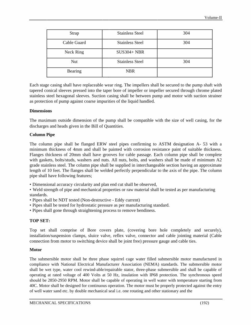
Volume-II
Strap Stainless Steel 304
Cable Guard Stainless Steel 304
Neck Ring SUS304+ NBR
Nut Stainless Steel 304
Bearing NBR
Each stage casing shall have replaceable wear ring. The impellers shall be secured to the pump shaft with tapered conical sleeves pressed into the taper bore of impeller or impeller secured through chrome plated stainless steel hexagonal sleeves. Suction casing shall be between pump and motor with suction strainer as protection of pump against coarse impurities of the liquid handled. Dimensions The maximum outside dimension of the pump shall be compatible with the size of well casing, for the discharges and heads given in the Bill of Quantities. Column Pipe The column pipe shall be flanged ERW steel pipes confirming to ASTM designation A- 53 with a minimum thickness of 4mm and shall be painted with corrosion resistance paint of suitable thickness. Flanges thickness of 20mm shall have grooves for cable passage. Each column pipe shall be complete with gaskets, bolts/studs, washers and nuts. All nuts, bolts, and washers shall be made of minimum A2 grade stainless steel. The column pipe shall be supplied in interchangeable section having an approximate length of 10 feet. The flanges shall be welded perfectly perpendicular to the axis of the pipe. The column pipe shall have following features; • Dimensional accuracy circularity and plan end cut shall be observed, • Weld strength of pipe and mechanical properties or raw material shall be tested as per manufacturing standards. • Pipes shall be NDT tested (Non-destructive - Eddy current) • Pipes shall be tested for hydrostatic pressure as per manufacturing standard. • Pipes shall gone through straightening process to remove bendiness. TOP SET: Top set shall comprise of Bore covers plate, (covering bore hole completely and securely), installation/suspension clamps, sluice valve, reflex valve, connector and cable jointing material (Cable connection from motor to switching device shall be joint free) pressure gauge and cable ties. Motor The submersible motor shall be three phase squirrel cage water filled submersible motor manufactured in compliance with National Electrical Manufacturer Association (NEMA) standards. The submersible motor shall be wet type, water cool rewind-able/repairable stator, three-phase submersible and shall be capable of operating at rated voltage of 400 Volts at 50 Hz, insulation with IP68 protection. The synchronous speed should be 2850-2950 RPM. Motor shall be capable of operating in well water with temperature starting from 40C. Motor shall be designed for continuous operation. The motor must be properly protected against the entry of well water sand etc. by double mechanical seal i.e. one rotating and other stationary and the
MECHANICAL SPECIFICATIONS (192)
Volume-II seal must be made of Silicon carbide/ Tungsten carbide and must be protected with sand protection guards. All supports shall be high grade cast iron and stator outer side jacket body should be in stainless steel in AISI 304. The excessive pressure due to heating up of the filled water must be compensated by a pressure equalizing rubber diaphragm in the lower part of the motor. The axial thrust of the pump shall be countered by oscillating sliding block type thrust bearing. The thrust bearing of the motor should be able to bear a download thrust force from the water pump and the upward thrust force produced while starting the water pump. Motor shall be capable of minimum of 20 starts in an hour. Motor efficiency shall not be less than 50%. Submersible Cable & Joint The submersible cable shall be made up of 99% copper coated with double PVC and shall be adequately flexible and environment friendly. The cable shall have undergone quality tests as per BSS standards. Following tests are mandatory.
Conductor resistance test
Insulation resistance test
Pressure test Spark test
The supplier shall provide the manufactures quality test certificate at the time of supply. The motor cable and drop cable shall be jointed together by means of a water resistant cable splicing kit.
Pressure Switch & Pressure Gauge A pressure switch and a pressure gauge with cock suitable for a range of 0 to 16 bar pressure shall be provided at the delivery pipe at suitable point to the approval of the Engineer. VALVES AND APPURTENANCES
All valves supplied shall be suitable for use with water temperatures upto 50oC and in climatic and soil conditions encountered in the Project Area. The nominal working pressure shall be 16 bar. All hydrants, valves and appurtenances shall be externally and internally fusion bonded epoxy coated using electrostatic/fluidized bed process with a minimum thickness of 300 microns, holiday-free and non-toxic. Before application of epoxy coating the surface shall be sand blasted to a minimum of SA 2.5 and air blown to ensure good bond. The valves shall be supplied complete with metal reinforced flange gaskets and galvanized steel nuts, bolts and washers. Unless otherwise detailed or specified herein, gate and butterfly valves shall be supplied complete with stainless steel type AISI 304L extension spindles and appurtenances such that the square nut operator is within 500 mm of the top of the chamber cover slab. All valves shall be tested to the appropriate test pressure at the manufacturer's works, and shall be supported by a test certificate from the manufacturer. Work tests on valves 300mm dia and larger shall be witnessed and certified by an approved independent testing agency at no extra cost to the Employer. Markings of valves shall include the following: - Manufacturing Standard - Manufacturer's Name or Trademark - Nominal Diameter(S) (N.D) In Mm Pressure Rating in Bars - An Individual Serial Number Which Relates Directly to The Manufacturer's Test Certificate - Month and Year of Manufacture. Position indicators shall be provided on all gate and check valves.
MECHANICAL SPECIFICATIONS (193)

Volume-II The maximum effort required to operate the valve against the maximum unbalanced head applied at the circumference of the hand wheel or end of the tee-key shall not exceed 15 kNm, where necessary gearing shall be provided. The Contractor shall supply the original manufacturer's test certificate endorsed by the approved independent testing agency for each valve supplied. The certificate shall relate to the individual number cast on each valve and shall give the date of test. Before proceeding with any manufacturing, submit Shop Drawings for Engineer's prior written
approval. Gate Valves Gate valves shall conform to the provisions of BS 5163 or approved equal and as further specified herein. The valves shall be inside screw, non-rising stem, clockwise closing wedge gate valves suitable for underground use. The direction of opening and closing shall be clearly marked. The minimum designed working pressure shall be 16 bar. Valve pressure ratings shall equal the class of pipe and shall be designed for the "Closed End Test". All gate valves shall be designed to provide 100% water tight shut off at all specified pressures. Valves shall be clock-wise closing using a square nut operator. Valves above 300mm dia shall be gear operated and hand wheels shall be provided where directed by the Engineer. Air Valves Air valves shall be designed to (a) Discharge air during filling of pipelines (b) Admit air during emptying of pipelines (c) Discharge air accumulated at high points in pipelines during normal operation. Double orifice air valves which shall combine both large and small orifices within one valve. The large orifice shall be sealed by a buoyant rigid ball and the chamber housing shall be designed to avoid premature closing of the valve by the air whilst being discharged. The small orifice shall be sealed by a buoyant ball at all pressures above atmospheric, except when air accumulates in the valve chamber. Air valve bodies shall be flanged, with flanges drilled to PN 16 in accordance with BS 4504. Each valve or valve assembly shall be installed complete with isolation valve whether or not indicated on the Drawings. Valves shall be designed for a water working pressure of not less than 16 bar and shall have floats and all working parts made of stainless steel seat of nitrile rubber with body and cover of ductile iron. Check Valves Check valves shall be mounted horizontally and be double flanged. Check valves shall be swing check valves to BS 5153 PN 16 straight pattern metal seated, flanged BS
4504 PN 16 temperature range of -10oC to 65oC. The face to face length shall be short. Provision shall be made for a body tapping on value as per BS standard.
MECHANICAL SPECIFICATIONS (194)

Volume-II Flow Meter Flow meter will be of different sizes ranging from 3” to 8”. Its installation can be in horizontal or vertical. The flow meters should be operating at temperatures up to 50°C and a maximum working pressure of 16 bar. Accuracy should be maintained in both forward and reverse flow. The meter complies with all relevant international quality standards, substantially exceeding ISO4064 BS5728 Class B specifications for forward flow installations in horizontal, vertical and inclined pipelines. Pressure Gauge Pressure gauge will be provided vertically on delivery main. Gauges mounted directly on piping should be assembled with reasonable care, always using wrench grip provided on pressure connection to secure it to the threading fitting. Gauges should be free of piping strains when mounted. If mounting surface, us uneven, insert washers under flange of the gauge case to obtain a three-point suspension. Case should be made of stainless steel and ring should be threaded or crimped. Its window should be of glass or clear plastic or shatter resistant glass. Its connection will be bottom male and lower back male Its dial Size should be ranging from 3” to 6”. The maximum pressure at which a pressure gauge is continually operated should not exceed 75% of full scale pressure. Water Chemical Testing The proposed water supply source to be used for water of domestic needs should be of acceptable quality in accordance with the guidelines of World Health Organization (WHO) which is presently being followed in Pakistan. Table shows the WHO Guidelines for Potable Water Quality. Table: WHO guidelines for portable water quality
Sr. No Parameter
W.H.O. Desirable W.H.O Maximum
levels permissible levels
1 Temperature o C - -
2 pH 7.0-8.0 6.5-8.5
3 Odour Unobjectionable Unobjectionable
4 Colour 5 Units 50 Units
5 Taste Unobjectionable Unobjectionable
6 Turbidity N.T.U. 5 Units 25 Units
7 Total dissolved solids 500 1500
8 Calcium 75 200
9 Magnesium 50 150
10
Total Hardness mg/l as 100 500
CaCO3
11 Sulphates 200 400
12 Chlorides 200 250
13 Iron 0.1 0.3
MECHANICAL SPECIFICATIONS (195)

Volume-II
NEW TUBE WELLS
Volume-II
SECTION T 01
TUBE WELL SPECIFICATIONS
CONSTUCTION OF TUBE WELL SCOPE The work covered by this Section of the Specification shall consist of all plant, labour, equipment, appliances, materials etc. as necessary for the well drilling, installation of materials, well completion, development, testing and miscellaneous work required for the satisfactory completion of all work involved with the construction of tubewells for water supply system. DRILLING General The Contractor shall drill each bore hole for water supply wells at the location established in the field by the Engineer. The Contractor shall prepare the site for the construction of the tubewell and shall provide for the disposal of water, cuttings, and refuse from his operations away from the tubewell. Drilling Procedure The bore hole shall be drilled by the reverse circulation rotary method with a minimum drill bit diameter of 22/ 18 inches as per project requirement mentioned in Bill of Quantities. The contractor at his own risk and with the permission of the engineer may adopt other method of drilling at locations where sub-surface conditions are such that the reverse circulation rotary method is not feasible or suitable in which case the contractor shall not be entitled to any extra claim. Each bore hole shall be drilled to the depth specified by the Engineer. It is anticipated that the depth of tubewells will vary; however, no minimum depth for any individual tubewell or average depth for all tubewells is guaranteed. The bore holes shall be drilled sufficiently straight and plumb so that the pump and tubewell casing may be installed concentric with the hole and within the tolerance specified for plumpness of the casing. Waste materials from the drilling operation shall be disposed off in a manner approved by the Engineer. The Contractor shall be responsible for protecting the tubewells from contamination by foreign material until the completion of the tubewell. The Contractor shall bear any expense that may result from damage to any tubewell, tools, or equipment that may be caused by caving, washing, or other disturbances within the tubewell. Where necessary to prevent sloughing and caving of surface material, the Contractor shall furnish and install a conductor casing with a minimum diameter 2 inches greater than the bit diameter not less than 6 inches above the ground surface upto a sufficient depth to encounter firm material. The conductor casing shall be new or used pipe of adequate strength for the purpose. After the drilling is completed, the conductor casing shall be removed by the Contractor and shall remain his property. If unstable material is encountered during drilling, the Contractor shall stabilize the material in a
TUBE WELL SPECIFICATIONS (196)
Volume-II manner approved by the Engineer. The use of drilling fluid additives or other suitable materials specially approved by the Engineer may be employed in stabilizing the bore hole. All temporary casing shall be removed by the contractor in 5 to 10 feet stages as ground shrouding is placed. If in the opinion of the Engineer, it is necessary to discontinue work on any bore hole because it is out of line more than the amount specified or on account of jammed tools, caving ground, or because of negligence on the part of the Contractor, the Contractor shall drill another bore hole at an alternative location designated by the Engineer. The Contractor will not be entitled to payment for any work done or materials furnished for bore holes abandoned as a result of his operation or negligence. Data and Records
The Contractor shall keep an accurate drilling log of each bore hole including a description of all materials encountered and their location in the bore hole. The fact that the Engineer or his representative may be present and keeping a separate record shall not release the Contractor from this responsibility. In the case of defective or incomplete records the Contractor shall complete the records at his own expense. All records and data shall be kept by the Contractor on forms approved by the Engineer. The Contractor shall deliver to the Engineer the original of all records. Sampling Representative ditch samples or cuttings of the material penetrated shall be taken at every 5' interval or at each change in lithology encountered which ever is less of the bore hole. Special care shall be exercised to determine the thickness and location of each change in material encountered and to obtain satisfactory samples. Immediately upon taking each sample, the sample shall be placed in a plastic or cloth bag, partitioned wooden box or other approved container, properly marked for identification, and plainly labeled with the depth of the top and bottom of the section of the bore hole represented. The containers shall be furnished by the Contractor. The method of obtaining, processing, and storing the samples will be subject to approval by the Engineer. The Contractor shall deliver all samples to the Engineer at the site of the tubewells, except that when requested to do so by the Engineer, the Contractor shall deliver specified samples to the Engineer's field headquarters. INSTALLATION OF WELL CASING
General
Installation of casing shall consist of all work required in connection with the installation of casing pipe, comprising mild steel housing pipe, blind pipe, reducer, sand trap and PVC screen required for each tubewell as specified herein or on the Drawings or as directed by the Engineer and shall include, but not be limited to storing, fabricating and installing all pump housing and tubewell casing including concentric reducers. Materials
Pump Housing Pipe
TUBE WELL SPECIFICATIONS (197)
Volume-II Pump Housing Pipe shall be of mild steel of designated diameters and wall thickness indicated in the drawings or BOQ. The pipes shall be made from steel plates conforming to ASTM Specifications A-53/79. The pipes shall have beveled ends. The pipe shall be furnished in standard lengths of 16 ft. and shall be painted outside with antirust chemical. All pipes shall be free from dents, injuries, scars and ovalties. The housing pipe shall be installed to extend a minimum 3' above ground level in addition to the housing as specified by the final design below ground level. Well Blind Pipe
Well blind pipes shall be of PVC BSS Class 'D' working pressure as mentioned in BOQs and drawings. Well blind pipes shall be of designated diameters as indicated in the drawings or mentioned in BOQ. Reducer
For connecting M.S. housing pipe and well blind pipe at depths below ground level a transitional reducer shall be provided and made of the same material and of the same thickness as used for well casing specified above. Sand Trap/Bail Plug
Sand trap shall be of the same material and thickness as followed for well casing. Sand trap shall be provided with a base plate, welded at one end of the pipe. A steel hook bent in the form of 'U' shall be bolted to the base plate to sustain a maximum suspended length of 500 ft. of well casing. Sand trap shall be 10 feet long in sizes as indicated in the drawing. Well Screen
Well screen shall be of PVC or as mentioned in drawings suitable for gravel pack tubewell and strong enough for location at a depth not exceeding 400 ft. below ground level. The strainer shall have minimum open area of 10 percent, minimum wall thickness of 0.25 inch and slot size of 0.04 inch. The slots shall be of a shape that produces an opening of a 'V' form, narrow on the outside and wide on the inside. The openings shall be free from jagged edges, irregularities or any thing that will accelerate or contribute to clogging or corrosion of the screen. Fabrication
The depth of pump housing casing will be established by the Engineer for each tubewell depending on the future water levels and draw down anticipated. Lengths of the specified diameter of steel casing shall be provided to extend the pump housing casing from the elevation of the top of the pump housing casing to the depth established by the Engineer.
TUBE WELL SPECIFICATIONS (198)

Volume-II Adjoining sections of pump housing casing shall be assembled by field welding. The ends of the casing sections shall be lathe turned or otherwise prepared for jointing. All field welding shall be performed by the electric arc method, using heavily coated welding rods suitable for all-position welding. After being welded, the welds shall be cleaned of slag and shall show uniform smooth sections, feather edges without overlap, and from porosity and clinkers. The pump housing casing shall be connected to the tubewell casing by means of a concentric tapered reducer having a minimum length of 24 inches. The length and sizes of tubewell casing to be installed shall be specified for each tubewell by the Engineer and shall be sufficient to extend from the bottom of the housing casing to the bottom of the tubewell. The bottom of the tubewell casing shall be provided with bail plug as shown on the drawings. The tubewell casing shall consist of slotted sections for installation opposite water yielding formations and plain pipe sections or bail plug opposite non- water yielding formations as directed by the Engineer. Installation
The Contractor shall install the entire pump housing and tubewell casing assembly straight, plumb, and concentric in the drilled hole to permit the installation of the pump in such a manner that it will operate satisfactorily and without damage. The methods employed by the Contractor in the installation of the casing and in obtaining or correcting the verticality and straightness of the pump housing casing shall be subjected to the approval of the Engineer. Centralizers, spacers or other suitable devices shall be attached to the tubewell casing so that it will be centered in the drill hole throughout its entire length and held in such position while gravel shrouding is being placed. Centralizers shall be attached to the pipe in a manner that ensures that the pipe is accurately centered in the drill hole. The detail design of centralizers and the method of attachment to the pipe shall be subject to the approval of the Engineer. Unless otherwise directed centralizers shall be spaced at no more than 60 ft. along the overall length of screen and casing assembly. The Contractor shall install the pump casing so that the deviation of its axis from the vertical shall not exceed 4 inches at the bottom of the pump housing casing. Measurements for determination of verticality and straightness of the pump housing casing shall be made by the Contractor in the presence of the Engineer upon completion of the gravel shrouding. Measurements for determining the deviation of the pump housing casing from the vertical shall be made by the use of a circular plumb having a minimum outside diameter of 1 inch less than the inside diameter of the pump housing casing. The plumb shall have vertically and shall be suspended in the centre of the pump housing casing from a point 10 ft. above the top of the casing. When the plumb is lowered to the bottom of the pump housing casing, the line from which the plumb is suspended shall not deviate from the centre of the pump housing casing at the top by more than corresponding to at deviation of the plumb 4 inches at the bottom of the pump housing casing. All deviations shall refer to a vertical line passing through the centre of the pump housing casing to the top of the pump
TUBE WELL SPECIFICATIONS (199)

Volume-II housing casing. Straightness shall be determined by lowering a section of pipe 40 ft. long or a dummy of the same length to the bottom of the pump housing casing. The minimum diameter of the pipe or dummy shall be 1 inch less than the inside diameter of the pump housing casing. If a dummy is used, it shall consist of a rigid spindle with three cylindrical rings, each ring having a height of at least 12 inches. The rings shall be true cylinders and shall be located at each end and in the centre of the dummy. The central shaft of the dummy shall be rigid so that it will maintain the alignment of the axis of the cylindrical rings. The pump housing casing shall be sufficiently straight so the pipe or dummy can be passed freely throughout the entire length of the pump housing casing. Plumbs, pipes and dummies used in these tests shall be approved by the Engineer. Any tubewell failing to meet the specified requirements for straightness, verticality and concentricity shall be abandoned, and the Contractor shall construct a new well at his own expense at an alternative site designated by the Engineer. After completion of installation of the pump housing casing and approval of the installation by the Engineer, the Contractor shall paint the letter and number designation of the tubewell on that portion of the pump housing casing which projects above the ground surface. All paint, brushes, stencils and other materials required shall be furnished by the Contractor. The characters shall not be less than 6 inches shall be painted with lines 1-inch-wide, and shall be positioned on the casing in accordance with the Engineer's instructions. Gravel Makeup Pipe
A 3 inch diameter (pvc or as mentioned) in drawings gravel makeup tremie pipe with capped upper end shall be attached to the upper pump house casing to extend from 3 feet above ground level to penetrate the full length of the upper grout seal. The tremie pipe shall be attached to the pump house casing by means of welded straps spaced no less than to provide four support straps spaced over the length of the pipe. Support shall be sufficient to hold the pipe in place until placement of the upper grouted seal has been completed. The configuration shall be in accordance with the drawings and the pipe shall be located so as to be at 90 degrees to the direction of the pump outlet. GRAVEL SHROUDING
General
Gravel shrouding shall consist of all work required in connection with supply and placing of gravel shrouding in annular space between the walls of the drilled hole and the outside of the pump casing. The work shall include, but not limited to development of source, excavation, stock piling, grading, washing, storing, transporting and placing of gravel shrouding as specified herein or as directed by the Engineer. Gravel Source The Contractor may obtain gravel from any source or location subject to the approval of the Engineer
TUBE WELL SPECIFICATIONS (200)
Volume-II provided that the gravel meets the requirements of the specifications. The Employer will not be responsible for the amount of work involved or the amount of materials wastage in order to obtain the required amount of gravel of proper gradation. Specifications
The gravel shrouding shall be clean, washed, water worn, hard, well rounded of siliceous material and without platy particles free from gypsum shale under no circumstances shall contain >5% calcareous material. The gravel supplied shall be subject to inspection and screening in the field to ensure proper gradation suitable to the formation. The gravel shall be reasonably graded and shall conform to the following requirements:
TYPICAL GRADING ------------------------------------------------------------------------------------------------------
U.S. Standard Percentage Screen Number Passing
------------------------------------------------------------------------------------------------------ 3/8 inch 100 No.4 75-100 No.8 35-65 No.14 05-30 No.16 00-15 No.35 00-0 ------------------------------------------------------------------------------------------------------
Placing of Gravel
Gravel shall be placed at constant rate using tremie pipe, hoppers or other similar devices to provide a continuous and uniform gravel flow so as to minimise segregation of particle sizes. When tremie pipe or hoppers are used, gravel shall be introduced in the annular space between the pump-housing and the edge of the hole at two points located 180 apart. The tremie pipe, when used, shall be of suitable size and lowered to the bottom of the well on two opposite sides of the bore hole and calculated quantity of gravel shall be poured in the pipe through a funnel and the pipe shall be raised by 6 ft. interval. In all cases water shall be circulated steadily during gravel placement by inserting the drilling rod into pump housing and operating the circulation pump on the drilling rig. The water level in the annular space outside the pump housing shall be maintained at or above natural ground surface level by return flow from the cutting bit. Temporary casing, if used, shall be carefully withdrawn in 6 to 10 ft. interval during placement of gravel shrouding and the gravel shall be introduced so that each stage of the hole above bottom of the casing is completely filled before the casing is withdrawn to the next stage. The process of withdrawing the temporary casing shall be continued until the bottom of temporary casing is at least 10 ft. above the top of the top most screen. Above this point the temporary casing shall be removed.
TUBE WELL SPECIFICATIONS (201)

Volume-II GROUTING OF PUMP HOUSING CASING
General
Grouting of pump housing casing shall cover providing all equipment, labour and doing all work required to seal the annular space between the pump housing casing and the bore hole face by the introduction of grout as specified herein and on the Drawings according to procedures approved by the Engineer. Material
The grouting operation shall be done with 1:2 cement sand mortar. Cement and sand shall conform to the requirements of Section "CONCRETE". Placement of Grouting The grout may be placed by either the trimmie method or by being pumped into place provided that
both the method and the type of grout is approved by the Engineer prior to the start of the operation. If the trimmie method is selected and approved the grout material shall be placed by trimmie pouring, (after water or other drilling fluid has been circulated in the annular space sufficient to clear obstructions). The trimmie method shall be used where there is a minimum annular space of 3 inches only between the upside surface of the inside casing and the inside surface of either the external casing or the borehole. The minimum size trimmie pipe utilized shall be 2 inches inside diameter. Where concrete grout is used the minimum size trimmie pipe used shall be three inches inside diameter. When making a trimmie pour, the trimmie pipe shall be lowered to the bottom of the zone being grouted and raised slowly as the grout material is introduced. The trimmie pipe shall be kept full continuously from start to finish of the grouting procedure, with the discharge end of the trimmie pipe being continuously submerged in the grout until the zone to be grouted is completely filled. The minimum curing time before construction may be resumed is 72 hours. If the method of grout placement selected and approved is to be by pumping, the grout shall be injected (after water or other drilling fluid has been circulated in the annular space sufficient to clear obstructions) in the annular space between the inner casing and either the outer casing or the borehole. The annular space must be a minimum of 1½ inches for sand and cement of neat cement grout, and not less than three times the size of the largest coarse aggregate used. The grout pipe shall extend from the surface to the bottom of the zone to be grouted. The grout pipe shall have a minimum inside diameter of one inch for sand cement of neat cement grout. It shall have a minimum diameter of 1½ inches for concrete grout. Grout shall be placed, from bottom to top, in one continuous operation. The grout pipe may be slowly raised as the grout is placed but the discharge end of the grout pipe must be submerged in the emplaced grout at all times until grouting is completed. The grout pipe shall be maintained full, to the surface, at all times until the completion of the grouting of the entire specified zone. In the event of interruption in the grouting operation, the bottom of the pipe should be raised above the grout level and should not be re-submerged until all air and water have been displaced from the grout pipe and the pipe flushed clear water. Curing time before construction may be resumed is minimum of 72 hours.
TUBE WELL SPECIFICATIONS (202)

Volume-II DEVELOPMENT AND TESTING
General
Development and testing shall consist of all work required in connection with the development of each tubewell to produce the design capacity of sand-free water with a minimum draw-down, and the testing of each tubewell to determine the effectiveness of the development operations as specified herein. Development and testing shall include, but not be limited to surging, backwashing and pumping the tubewell at higher than rated capacity; testing the tubewell for specific capacity, sand content and degree of development and disinfection and sealing each tubewell. The Contractor shall be required to sound the well, to determine whether excess sand has accumulated in the bottom of the well at the following stages of the work: (i) On completion of the casing and screen installation (ii) Before the starting of the development and (iii) After completion of development and testing
If it is found at any stage mentioned above that the well contains more than 3 ft. of sand or other material in the bail plug, the Contractor shall clear the well down to a level approximately 3 ft. above the bottom plate of the bail plug. Water obtained in development and testing shall be disposed of by the Contractor in an approved manner. No separate payment will be made for the first 20 hours of development and testing for each tubewell. Development and testing ordered by the Engineer in excess of 20 hours per tubewell will be paid for at the quoted unit price for this item. Development The development procedure and methods used for development of the tubewells shall be established by the Contractor subject to approval by the Engineer and the development operations shall be witnessed by the Engineer, from their initiation to their completion. The Contractor shall maintain a complete record of the development operation and shall make regular periodic measurements of discharge rates, sand content and water level measurements. The procedures used shall include back washing and pumping at 1.5 times the rated capacity and may include surging or similar procedures determined by the Contractor. The Contractor shall notify the Engineer following the completion of the 6 hours pumping period, that the tubewell is ready for testing. In wells where bentonite or other formation stabilizing agents are used, the Contractor shall undertake a programme of cleaning the well with poly phosphates or other dispersing agents in a manner and with chemical dosages as approved by the Engineer prior to starting normal development work. Testing The contractor shall test each tubewell under the direction of the Engineer as described herein. Upon
completion of the development operations the tubewell shall be permitted to recover for a minimum
TUBE WELL SPECIFICATIONS (203)
Volume-II period of one hour. During this recovery period, the tubewell shall be sounded. If the comparison of the depth by sounding and the length of the casing string indicates that there is more than 6.00 feet of material in the tubewell, it shall be cleaned to within 2.0 feet of the bottom of the casing by bailing. At the end of the first five minutes of pumping, the sand content of the water shall be determined by using a 40 inches Imhoff cone or other device approved by the Engineer. The sand content of the water at this time shall be less than 100 mg/1. A second sand content determination shall be made 10 minutes after the start of pumping. The sand content at this time shall be less than 30 mg/1. If the sand content tolerances are exceeded at this time, or at any subsequent time upto the time of final acceptance of the installation, sand content determinations, water level, and discharge measurements during the remainder of the one hour sand test period shall be made as directed by the Engineer. When the sand test has been satisfactorily completed, the tubewell shall be further developed for 4 hours by surging and backwashing with the test pump at five to ten minute intervals. Following the development period, the tubewell shall again be pumped for a period of one hour during which time the sand test shall be repeated. The specific capacity of the tubewell shall be determined from the water level measurements and flow rates obtained during the pumping periods. If the specific capacity obtained from the second pump test is found to be more than 10 percent greater than that obtained in the first pump test, the development shall be continued as directed by the Engineer. Upon satisfactory completion of the above one-hour pumping period the tubewell shall be permitted to recover for a period of one hour. Upon the completion of this recovery period, a four-hour multiple step pump test shall be performed by pumping the tubewell for one hour at each of approximately four equal increments. Summary
The following is a summary of the development and testing procedure:
Development
Development time Recovery
6 hours (minimum) 1 hour (minimum)
Testing
Pumping Period Development Pumping period Recovery Step pumping Pumping period
1 hour 4 hour 1 hour 1 hour (minimum) 4 hour 2 hours
TUBE WELL SPECIFICATIONS (204)
Volume-II Equipment The Contractor shall furnish all necessary equipment for testing the tubewell, including a water lubricated or oil lubricated test pump, a valve for fine adjustment of the discharge, an electric measuring device to determine the drawdown during each stage of the test and Imhoff cones to measure sand content. If oil lubricated test pumps are used, the contractor shall exercise all reasonable precautions to keep the leakage of lubricating oil into the tubewell at a minimum and shall promptly remove all oil which collects on the water surface in the tubewell by the addition of detergents or other suitable chemicals and pumping the emulsified oil from the tubewell. In the event the Contractor fails to keep the leakage of oil into the tubewell within acceptable limits or to promptly remove oil accumulations from the tubewell, the Engineer will order the use of oil lubricated test pumps discontinued and the Contractor shall use water lubricated pumps for testing of the tubewells. The actual depth of setting for the test pump will be determined by the Engineer after the tubewell has been developed. Piping, gauges, orifices, meters, wire boxes or other measuring devices shall be furnished, installed and removed by the Contractor and will remain his property. All measuring devices and testing equipment shall be subject to approval by the Engineer. Measurements and Data
The Contractor shall take drawdown and discharge measurements and other pertinent data during each test at intervals as specified by the Engineer. All such data shall be recorded on forms approved by the Engineer, and the original of such forms shall be delivered to the Engineer at the completion of the development and testing operations. The contractor shall collect water sample from tubewell, after completion of the D & T. Water samples shall be completely tested from any approved laboratory and result shall be submitted to the engineer at the completion of the tubewell. Disinfection and Sterilization
After development and testing of the tubewell has been satisfactorily completed, and when approved by the Engineer, the Contractor shall disinfect the tubewell by dispersing chlorine solution throughout the entire depth of the well to obtain a minimum chlorine content of 50 mg/1. The procedure and equipment used to introduce and disperse the chlorine in the tubewell shall be subject to approval by the Engineer. Sealing of the Well
Upon completion of the tubewell the Contractor shall seal the tubewell with a ¼ inch thick steel plate cap welded to the pump housing at few points using Arc welding, or by some other method approved by the Engineer. Compliance with this requirement will not relieve the Contractor of his responsibility for the safeguarding of any part of the tubewell completed until the Certificate of Acceptance is issued for the entire tubewell installation.
TUBE WELL SPECIFICATIONS (205)
Volume-II EXISTING PUMPING AND WELL TESTING The Contractor is required to submit his methodology on trial pumping and well test, and information prior to the test works. This proposal shall include the following items but not limited to depending on the site condition to for Engineer review and prior to execution.
• Schedule of Pumping Test & Field Staffs with Cellular Phone Number. • Pump Facility (the contractor has to arrange-cost In built); expected Discharge
(m3/min.) (This would be proposed discharge after monitoring activity), power source (available electricity by Govt otherwise DG set to arrange).
• Jetting Facility where required and as directed by Engineer: design drawing (video logging report & bore hole log), water pressure (kgf/cm2 or MPa), water discharge (L/min).
• Sounding Tube: material, diameter, installation depth. • Discharge Measure: equipment, draining-way with safety arrangement.
Contractor will need to carry out the pumping test to know the existing specific capacity and efficiency of the tube well comprising of the following but not limited to:-
Performance monitoring of pumps Water Table Draw Down Discharge & Yield Well Sounding and Sand contents, etc.
o Drawdown Test: shall be measured just before the pumping test started, during pumping period water level shall be measured at every one minutes until 10 minutes, every 5 minutes until one hour, every 10 minutes until 2 hours using sounding tube.
o Discharge: Pumping rate shall be measured by the methods of ultrasonic flow
meter or any other appropriate device as approved by Engineer. Frequency of measuring is every one hour until pumping finished.
o Measuring of water level: it shall be conducted by insertion of the sounding tube
into the test wells. The measuring of water level during pumping test shall be conducted by insertion of the measuring device into the sounding tube which is set in test wells. Any ultrasonic signal device if appropriate may also be used (if approved by the Engineer).
Submittals The Contractor shall submit the following reports to the Engineer.
Overall Work Schedule, Location Map & list of Instrument/ Equipment Site Report (binding of proposal/ data sheet/ analysis) Photo album (well site, discharge measuring, draining situation Data Sheet (location, date, time, elevation, water level, discharge rate, etc.) Performance monitoring of existing pumping as per sample below or as directed by
Engineer
TUBE WELL SPECIFICATIONS (206)

Date: Pump Data Motor Data Location: Make Make System: Pump Type Model Daily Operating Hours Rated Power Static Water Level (m) Rated Discharge ( Q ) m3/hr Full Load Speed rpm Pump Setting Depth (m) Rated Head ( H ) M Full Load Efficiency Speed ( RPM ) Full load Current Impeller Dia ( mm ) Rated Efficiency ( % ) % Suction Dia. (Ds) Inch Discharge Dia. (Dd) Inch
Fully Open Throttled Throttled Fully Close
Sr. # Parameter Unit Method Point-1 Point-2 Point-3 Point-4
Routine 1 Disch. Pressure (pd) bar Measured
2 Flow (Q) m3/h Measured 3 Pumping Water Level (hpl) m Measured
4 Voltage (V) Volt Measured
5 Ampere (A) Amp Measured
6 Power Factor (Cos ø ) Nil Measured
7 Motor Input Power (P input) KW Measured
8 Speed (N) RPM Measured
9 Disch. Head (hd) m Calculated
10 Frict. Losses ( Discharge Head) m Technical Manual
11 Frict. Losses ( Column Pipes) m Technical Manual
12 Static Disch. Head Hsd m Calculated
13 Disch. Velocity (vd) m/s Calculated
14 Velocity Head (hvd) m Calculated
15 Total Dynamic Head HTD m Calculated
16 Water Power (Pw) KW Calculated
17 Motor Efficiency (ήm) % Assumed
18 Motor Output Power (Poutput) KW Calculated
19 Power loss (Shaft Friction) KW Calculated
20 Pump Power Input KW Calculated
21 Pump Efficiency (ήPump) % Calculated
Comments & Recommendations
SECTION – P 01
G.I PIPES
(229)
SECTION - P 01
GALVANIZED IRON (G.I) PIPES 1. SCOPE The work under this section of the specifications includes furnishing all plant, labour, equipment,
appliances, materials and in performing all operations required in connection with providing and laying of Galvanized Iron Pipes and Pipe fittings, in accordance with the Contract or as directed by the Engineer and the manufacturer's recommendations.
2. MATERIALS 2.1 General
The galvanized iron (GI) pipes are used for water supply system, particularly in hilly areas and the streets of narrow width. The GI pipes can be laid at ground level in order to avoid the excavation of trenches. Generally, the medium class pipe is used for gravity mains as well as for pressure mains of water supply through direct pumping from tube wells. The galvanized iron pipes shall strictly conform to BS 1387-1967 "medium quality" Specifications for "Steel Tubes and Tubulars suitable for screwing to BS 21 pipe threads" and tested to a hydraulic pressure of not less than 50 kg/cm2. All screwed pipes and sockets shall be of wrought iron having BS 1740. A complete and uniform adherent coating of zinc white will be provided for galvanized iron pipes and fittings. The pipes shall be free from defects such as pinholes and leaks, galvanized internally and externally and obtained from an approved manufacturer.
Malleable iron fittings for steel tubes shall be similar to BS 143 and 1256, tested to a hydraulic pressure of 21 kgF/cm2 and galvanized as specified in the B.S.
Jointing of galvanized iron pipes shall be by standard screw thread sealed with PTFE tape. Galvanizing damaged or removed by cutting, jointing, or threading shall be made good with approved cold galvanizing compound. The analysis of GI pipes is as under:
2.2 Specification and Standards
British Standard: BS 1387 (for galvanizing)
BS 21 (for threading)
American Standard: ASTM A-53
European Standard: EN 10240
German Standard: DIN 2444

(230)
2.3 Length Generally 6.0 meter + 06 mm. (Can be supplied in customized length of 4.88 meter to
7.00 meter.)
2.4 Thickness
Extra Light & Light Tubes - 8 %
Medium & Heavy tubes - 10 %
2.5 Outer Diameter
In accordance with BS-1387 standard In accordance with ASTM A-53
2.6 Weight
One single tube -8%, +10%; Mean consignment weight±4 %
2.7 Straightness
0.2% of any length measured along the centre line or on customer requirement. 2.8 Raw Material
Carbon: 0.2% max, Manganese: 1.2% max,
Phosphorus: 0.045% max, Sulphur: 0.045% max
2.9 Zinc Coating Thickness
300 ~ 400 gms per square meter of tube
3. HANDLING AND STORAGE 3.1 General The Contractor shall be responsible for proper handling, as per manufacturer’s
recommendations, of pipes and pipe fittings etc. All the material shall be stacked in accordance with the manufacturer's recommendations at approved places as directed by the Engineer. Packing shall be done bundling hexagonally by sealing metal straps and each bundle is tagged for size, thickness, weight etc. Product can be supplied with galvanized sockets.
3.2 Transport

(231)
Transportation of pipes shall be done in such a way that they are secure and that no more
than an absolute minimum of movement can take place on the vehicle during transit. The same care is needed if pipes are to be transferred from one vehicle to another, how short the final journey may be.
3.4 Storage Pipes, and fittings damaged during handling, transporting or lowering shall be rejected
and replaced at the contractor's expense. Storage shall be under shades. 3.5 Stringing and Inspection Stringing, consists of placing pipes on the ground in line ready for laying. Care is again
needed to prevent damage during this operation. The turned ends of all pipes shall be inspected to ensure that they are free from any local
irregularities which could affect the water tightness of the joint. All pipe shall also be visually inspected for evidence of impact damage. When such damage is detected, a thorough examination of internal surface in region of the pipe ends shall be made for sign of hair cracks. Damaged pipes, joints, and fittings shall be rejected and replaced at the expense of the Contractor.
4. MEASUREMENT AND PAYMENT 4.1 General
Except otherwise specified herein or elsewhere in the Contract Documents, no separate measurement and payment will be made for the under mentioned works related to the relevant items of the Bills of Quantities. The cost thereof shall be deemed to have been including in the quoted unit rate of the respective items of Bills of Quantities.
7.1.1 Submission of sample 7.1.2 Transportation 7.1.3 Stacking and stringing 7.1.4 Jointing/welding 7.1.5 Cutting, turning and jointing of pipes 7.1.6 Flushing, Testing and Disinfection & Commissioning of pipe line 7.1.7 All other associated works as mentioned in BOQ / Preamble to BOQ 4.2 Measurement of G.I Pipe Measurement of acceptable completed works of supply, erection and installation of pipes
and fittings will be made on basis of actual length in running meter of pipes provided and installed in position as shown on the drawings or as directed by the Engineer.
4.3 Payment Payment will be made for acceptable measured quantity of supply, erection and
installation of GI pipes and fittings on the basis of unit rate per running meter quoted in

(232)
the bills of quantities and shall constitute full compensation for all the works related to the item.
END OF SECTION

(233)
SECTION – P 02
VALVES

(234)
SECTION – P 02
VALVES
PART 1 - GENERAL 1.1 DESCRIPTION:
A. The Work under this Section consists of furnishing and installing all the valves required for the mechanical systems as shown on the drawings and specified herein.
1.2 REFERENCES:
A. ANSI - American National Standards Institute
ANSI B2.1 Pipe Threads. ANSI B16.1 Cast Iron Pipe Flanges and Flanged Fittings, Class 25, 125, 250, and
800. ANSI B16.11 Forged Steel Fittings, Socket-Welding and Threaded. ANSI B16.18 Cast Copper Alloy Solder Joint Pressure Fittings. ANSI B16.24 Bronze Pipe Flanges and Flanged Fittings, Class 150 and 300. ANSI B16.25 Butt Welding Ends.
B. BSI - British Standards Institute
BS 21 Pipe Threads for Tubes and Fittings. BS 143 Malleable Cast Iron and Cast Copper Alloy threaded Pipe Fittings. BS 1560 Steel Pipe Flanges. BS 4504 Flanges and Bolting for Pipes, Valves and Fittings. BS 5154 Copper alloy Globe, Globe Stop, and Check, Check and Gate valves
C. ASME - American Society of Mechanical Engineers
ASME B31.1 Power Piping - ASME Code for Pressure Piping.
ASME B31.9 Building Services Piping - ASME Code for Pressure Piping.
D. ASTM - American Society for Testing and Materials
ASTM A 126 Specification for Gray Iron Castings for Valves, Flanges, and Pipe Fittings.
ASTM B 62 Specification for Composition Bronze or Ounce Metal Castings.

(235)
1.3 SUBMITTALS:
A. Product Data: Submit manufacturer's technical product data, including body material, valve design, pressure and temperature classification, end connection details, seating materials, trim material and arrangement, dimensions and required clearances, and installation instructions.
1.4 TRANSPORTATION, HANDLING AND STORAGE:
A. Deliver materials to job site in manufacturer's original new and unopened packages bearing manufacturer's name and label. Ensure valves are dry and internally protected against rust and corrosion. Protect valve ends against damage to threads, flange faces, and weld-end preps.
B. Protect valves from weather. Store valves indoors. Maintain valve temperature higher than
ambient dew point temperature. Support valve off the ground or pavement in watertight enclosures.
C. Use a sling to handle valves whose size requires handling by crane or lift. Rig valves to avoid
damage to exposed valve parts. Do not use hand wheels or stems as lifting or rigging points. 1.5 QUALITY ASSURANCE:
A. Comply with the requirements ASME B31.9 and applicable Standards of MSS. B. Manufacturer's Qualifications: Firms regularly engaged in manufacture of valves, of types
and sizes required whose products have been in satisfactory use in similar service for not less than 5 years, and shall be subject to approval of Engineer.
PART 2 - PRODUCTS 2.1 VALVE FEATURES:
A. General: Comply with ASME B31.9 for building services piping, and ASME B31.1 for power piping.
B. Valve Design: Valves shall have rising stem, or rising outside screw and yoke stems; except,
non-rising stem valves may be used where headroom prevents full extension of rising stems. C. Pressure and Temperature Ratings: As scheduled and required to suit system pressures and
temperatures. D. Sizes: Unless otherwise indicated, provide valves of same size as upstream pipe size.
E. Operators: Provide the following special operator features, where required:
1. Hand wheels: Fastened to valve stem, for valves other than quarter-turn. 2. Lever Handle: On quarter-turn valves 150 mm and smaller, except for plug valves.
Provide one wrench for every 10 plug valves. 3. Chain-Wheel Operators: For valves 63.5 mm and larger, install 1829 mm or higher
(236)
above finished floor elevation. Extend chains to an elevation of 1524 mm above finished floor elevation.
F. Extended Stems: Where insulation is indicated, provide extended stems arranged to receive
insulation.
G. Bypass and Drain Connections: Comply with MSS SP-45 bypass and drain connections.
H. End Connections: As specified in the individual valve specifications.
1. Threads: Comply with ANSI B2.1. 2. Flanges: Comply with ANSI B16.1 for cast iron, ANSI B16.5 for steel, and ANSI
B16.24 for bronze valves. 3. Solder-Joint: Comply with ANSI B16.18.
2.2 GATE VALVES:
A. Gate Valves 50.8 mm and Smaller: MSS SP-80; Class 125, body and bonnet of ASTM B 62 cast bronze, threaded or solder ends, solid disc, copper-silicon alloy stem, brass packing gland, Teflon-impregnated packing, and malleable iron hand wheel. Class 150 valves meeting the above shall be used where pressure requires.
B. Gate Valves 50.8 mm and Larger: MSS SP-70; Class 125 iron body, bronze mounted, with
body and bonnet conforming to ASTM A 126 Class B, flanged ends, and Teflon impregnated packing and two-piece backing gland assembly.
2.3 CHECK VALVES:
A. Swing Check Valves 50.8 mm and Smaller: MSS SP-80; Class 125, cast bronze body and cap conforming to ASTM B62, horizontal swing, Y-pattern, with a bronze disc, and having threaded or solder ends. Valve shall be capable of being re-ground while the valve remains in the line. Class 150 valves meeting the above specifications may be used where pressure requires or Class 125 are not available.
B. Swing Check Valves 63.5 mm and Larger: MSS SP-71; Class 125, cast iron body and bolted
cap conforming to ASTM A126, Class B, horizontal swing, with a bronze disc or cast iron disc with bronze disc ring, and flanged ends. Valve shall be capable of being refitted while the valve remains in the line.
2.4 FOOT VALVES:
A. Manufacturer's standard models, of sizes as shown on the drawings. Operating range pressure shall be up to 34 bar. Non-sticking, brass spool poppet design. Heavy red brass body for maximum strength and No.6 perforation. Brass screen strainer and rubber facing for use with water.
(237)
2.5 FLUSH VALVES:
A. Automatic flush (drain) valves shall be installed at the end of each lateral in which bubblers are installed and where indicated.
2.6 FLOAT VALVES:
A. For water level in water system with working pressure up to 1.5 kp/cm² (1.5 bar) shall be bronze gate provided with bronze rod and bronze float ball attachment. The ball shall be made of copper.
2.7 DRAIN VALVES
A. Drain Valves: Bronze body and angle hose end valve with composition discs and rising stems; working pressure shall be 10.5 kg/cm².
2.8 VALVE BOXES:
A. Shall be precast or of cast-in-place reinforced concrete with cast iron cover as shown on the drawings. Concrete shall be Class 30 conforming to Section 03300 - CAST-IN-PLACE CONCRETE, 30 MPa compressive strength at 28 days, with type V cement.
PART 3 - EXECUTION 3.1 VALVE INSTALLATION:
A. General Application: Use gate, ball and butterfly valves for shut-off duty; globe and ball for throttling duty. Refer to drawings and piping system specification sections for specific valve application and arrangement. Locate valves for easy access and provide separate support where necessary.
B. Install valves and unions for each fixture and item of equipment in a manner to allow
equipment removal without system shut-down. Unions are not required on flanged devices. C. Install 3-valve bypass around each pressure reducing valve using throttling type valves. D. Install valves in horizontal piping with stem at or above the center of the pipe. E. Swing check valves shall be installed in horizontal position with hinge pin level. F. Solder, threaded and flanged connections shall be as per the approved trade practice.
3.2 FIELD QUALITY CONTROL:
A. Testing: After piping systems have been tested and put into service, but before final adjusting and balancing, inspect each valve for leaks. Adjust or replace packing to stop leaks; replace valve if leak persists.
END OF SECTION

(238)
Section: P03
HIGH DENSITY POLYETHYLENE (HDPE) PIPE AND FITTINGS
PART 1: GENERAL
1. SECTION DESCRIPTION
This specification includes but is not limited to high-density polyethylene (PE 3408) (ductile iron pipe size O.D) pressure pipe primarily intended for the transportation of water and sewage either buried or above grade.
2. REFERENCES
AWWA C901 Polyethylene (PE) pressure Pipe & Tubing, ½ inch through 3 inch for water
AWWA C906 Polyethylene (PE) pressure Pipe & Fittings, 4 inch through 63 inch for water
ASTM D3035 Standard Spec for PE Pipe (DR-PR) Based on Controlled Outside Diameter
ASTM D3261 Butt Heat Fusion PE Fittings for PE Pipe & Tubing
ASTM D3350 Standard Specification for PE Pipe & Fittings Materials
ASTM D1238 Melt Flow Index
ASTM D1505 Density of Plastics
ASTM D2837 Hydrostatic Design Basis
NSF Std.#14 Plastic Piping Components & Related Materials
TR-33/2005 Generic Butt Fusion Joining Procedure for Field Joining of PE Pipe
3. GENERAL
A. USE
High Density Polyethylene (HDPE) pipes/fittings shall be allowed for use as water, wastewater and reclaimed water pressure pipe where compatible with the specific conditions of the project. The use of material other than HDPE pipe may be required by ASPA if it is determined that HDPE pipe is unsuitable for the particular application. All material used in the production of water main piping shall be approved by the National Sanitation Foundation (NSF).
B. DOCUMENTATION
Documentation from the resin’s manufacturer showing results of the following tests for resin identification:
Melt Flow Index ASTM D1238
Density ASTM D1505
C. MANUFACTURER
All HDPE pipe and fittings shall be from a single manufacturer, who is fully experienced, reputable and qualified in the manufacture of the HDPE pipe to be furnished. The pipe
(239)
shall be designed, constructed and installed in accordance with the best practices and methods and shall comply with these Specifications.
4. FINISHED PRODUCT EVALUATION
Production staff shall check each length of pipe produced for the items listed below. The results of all measurements shall be recorded on production sheets, which become part of the manufacturer’s permanent records.
a) Pipe in process shall be checked visually, inside and out for cosmetic defects (grooves, pits, hollows, etc.)
b) Pipe outside diameter shall be measured using a suitable periphery tape to ensure conformance with ASTM F714 or ASTM D3035, whichever is applicable.
c) Pipe wall thickness shall be measured at 12 equally spaced locations around the circumference at both ends of the pipe to ensure conformance with ASTM F714 or ASTM D3035, whichever is applicable.
d) Pipe length shall be measured.
e) Pipe marking shall be examined and checked for accuracy.
f) Pipe ends shall be checked to ensure they are cut square and clean.
g) Subject inside surface to a “reverse bend test” to ensure the pipe is free of oxidation (brittleness).
5. STRESS REGRESSION TESTING
The polyethylene pipe manufacturer shall provide certification that stress regression testing has been performed on the specific polyethylene resin being utilized in the manufacture of this product. This stress regression testing shall have been done in accordance with ASTM D2837 and the manufacturer shall provide a product supplying a minimum Hydrostatic Design Basis (HDB) of 1,600 psi as determined in accordance with ASTM D2837.
6. COMPATIBILITY
Contractor is responsible for compatibility between pipe materials, fittings and appurtenances.
7. WARRANTY The pipe MANUFACTURER shall provide a warranty against manufacturing defects of material and workmanship for a period of ten years after the final acceptance of the project by the OWNER. The MANUFACTURER shall replace at no expense to the OWNER any defective pipe/fitting material including labor within the warranty period.
(240)
PART 2: PRODUCTS 1. MATERIALS FOR PIPE SIZES 4-INCH DIAMETER AND LARGER
Materials used for the manufacture of polyethylene pipe and fittings shall be made from a PE 3408 high density polyethylene resin compound meeting cell classification 345434C per ASTM D3350; and meeting Type lll, Class C, Category 5, Grade P34 per ASTM D1238.
High Density Polyethylene (HDPE) pipe shall comply with AWWA Specifications C906.
If rework compounds are required, only those generated in the Manufacturer’s own plant from resin compounds of the same class and type from the same raw material supplier shall be used.
Dimensions and workmanship shall be as specified by ASTM F714. HDPE fittings and transitions shall meet ASTM D3261. HDPE pipe shall have a minimum density of 0.955 grams per cubic centimeter. All HDPE pipe and fittings shall have a Hydrostatic Design Basis (HDB) of 1,600 psi.
HDPE pipe and accessories 4-inch diameter and larger, shall be 160 psi at 73.4oF meeting the
requirements of Standard Dimension Ration (SDR) 17 as MINIMUM STRENGTH.
The pipe Manufacturer must certify compliance with the above requirements.
2. MATERIALS FOR PIPE SIZES 2-INCH DIAMETER AND LESS
Materials used for the manufacture of polyethylene pipe and fittings shall be made from a PE 3408 high density polyethylene resin compound meeting cell classification 345434C per ASTM D3350; and meeting Type lll, Class C, Category 5, Grade P34 per ASTM D1238.
High Density Polyethylene (HDPE) pipes shall comply with AWWA Specifications C901.
If rework compounds are required, only those generated in the Manufacturer’s own plant from resin compounds of the same class and type from the same raw material supplier shall be used.
Dimensions and workmanship shall be as specified by ASTM D3035. HDPE fittings and transitions shall meet ASTM D3261. HDPE pipe shall have a minimum density of 0.955 grams per cubic centimeter. All HDPE pipe and fittings shall have a Hydrostatic Design Basis (HDB) of 1,600 psi.
HDPE pipe and accessories 2” and less in diameter, shall be 160 psi at 73.4oF meeting the
requirements of Standard Dimension Ration (SDR) 9 as MINIMUM STRENGTH.
The pipe Manufacturer must certify compliance with the above requirements.
3. FITTINGS
All molded fittings and fabricated fittings shall be fully pressure rated to match the pipe SDR pressure rating to which they are made. All fittings shall be molded or fabricated by the manufacturer. No Contractor fabricated fittings shall be used unless approved by the Engineer.
The manufacturer of the HDPE pipe shall supply all HDPE fittings and accessories as well as any adapters and/or specials required to perform the work as shown on the Drawings and specified herein.
All fittings shall be installed using butt-fused fittings, thermo-fused fittings/couplings, or flanged adapters and must be approved by the Engineer. NO size on size wet taps shall be permitted.

(241)
All transition from HDPE pipe to ductile iron or PVC shall be made per the approval of ASPA Engineer and per the HDPE pipe manufacturer’s recommendations and specifications. A molded flange connector adapter within a carbon steel back-up ring assembly shall be used for pipe type transitions. Ductile iron back-up rings shall mate with cast iron flanges per ANSI B16.1. A 316 stainless steel back-up ring shall mate with a 316 stainless steel flange per ANSI B16.1.
No solid sleeves shall be allowed between such material transitions.
Fittings and transitions shall be as manufactured by Phillips DRISCOPIPE, Inc., 1000 Series Pressure Pipe, Chevron Chemical Company Plexco/Spiralite pipe, or equal.
The pipe supplier must certify compliance with the above requirements.
4. PIPE IDENTIFICATION
The following shall be continuously indent printed on the pipe or spaced at intervals not exceeding 5-feet:
i. Name and/or trademark of the pipe manufacturer.
ii. Nominal pipe size.
iii. Dimension ratio.
iv. The letters PE followed by the polyethylene grade in accordance with ASTM
v. D1248 followed by the hydrostatic design basis in 160’s of psi, e.g., PE 3408.
vi. Manufacturing standard reference, e.g., ASTM F714 or D-3035, as required.
vii. A production code from which the date and place of manufacture can be determined.
viii. Color Identification, either stripped by co-extruding longitudinal identifiable color markings or shall be solid in color and as follows:
BLUE – Potable Water
GREEN – Sanitary Sewer
ix. Tracing Wire
Open trench installation of HDPE shall be identifiable per ASPA Specification Sec. 02600, Part 2, 2.01 (A).
x. Directional Drilled HDPE shall have wire conforming to Copperhead Industries Reinforced #1245 Extra-High Strength Tracer Wire and affixed to the drilling head/reamer per Detail M-17.
xi. Marking Tape: Marking tape shall be installed per ASPA

(242)
O
O
O
PART 3: EXECUTION
1. JOINING METHOD
The pipe shall be joined with butt, heat fusion joints as outlined in ASTM D2657 and conform to the Generic Butt Fusion Joining Procedure for Field Joining of Polyethylene Pipe, Technical Report TR-33/2005, published by the Plastic Pipe Institute (PPI). All joints shall be made in strict compliance with the manufacturer’s recommendations. A factory qualified joining technician as designated by pipe manufacturer or experienced, trained technician shall perform all heat fusion joints in the presence of the ASPA inspector.
Lengths of pipe shall be assembled into suitable installation lengths by the butt- fusion process. All pipes so joined shall be made from the same class and type of raw material made by the same raw material supplier. Pipe shall be furnished in standard laying lengths not to exceed 50 feet and no shorter than 20 feet.
On days butt fusions are to be made, the first fusion shall be a trial fusion in the presence of an ASPA Inspector. The following shall apply:
Heating plate surfaces shall be inspected for cuts and scrapes and shall be free of dirt and residue. Heater surfaces should be between 400 F (minimum) to 450 F (maximum). Measure the temperature @ 12:00, 3:00, 6:00 and 9:00 o’clock positions using a pyrometer of infrared thermometer at locations where the heating plate will contact the pipe/fitting ends. The maximum temperature difference between any two points on a single heating surface must not exceed 24 F. If this temperature is exceeded, the heating plate shall be cleaned per th e manufacturer’s recommendations.
The fusion or test section shall be cut out after cooling completely for inspection.
The test section shall be 12” or 30 times (minimum) the wall thickness in length and 1” or 1.5 times the wall thickness in width (minimum).
The joint shall be visually inspected as to continuity of “beads” from the melted material, and for assurance of “cold joint” prevention (i.e. – joint shall have visible molded material between walls of pipe). Joint spacing between the walls of the two ends shall be a minimum of 1/16” to a maximum 3/16”.
The polyethylene flange adapters at pipe material transitions shall be backed up by stainless steel flanges conforming to ANSI B16.1 and shaped as necessary to suit the outside dimensions of the pipe. The flange adapter assemblies shall be connected with corrosion resisting bolts and nuts of Type 316 Stainless Steel as specified in ASTM A726 and ASTM A307. All bolts shall be tightened to the manufacturer’s specified torques. Bolts shall be tightened alternatively and evenly. After installation, apply a bitumastic coating to bolts and nuts.
(243)
PART 4: INSTALLATION
High Density Polyethylene (HDPE) Pipe shall be installed in accordance with the instruction of the manufacturer, as shown on the Drawings and as specified herein. A factory qualified joining technician as designated by the pipe manufacturer shall perform all heat fusion joints.
HDPE shall be installed either by Open Trench Construction or Directional Bore Method.
Care shall be taken in loading, transporting and unloading to prevent damage to the pipe. Pipe or fitting shall not be dropped. All pipe or fitting shall be examined before installation, and no piece shall be installed which is found to be defective. Any damage to the pipe shall be repaired as directed by the Engineer. If any defective pipe is discovered after it has been installed, it shall be removed and replaced with a sound pipe in a satisfactory manner by the contractor, at his own expense.
Under no circumstances shall the pipe or accessories be dropped into the trench or forced through a directional bore upon “pull-back”.
Care shall be taken during transportation of the pipe such that it will not be cut, kinked or otherwise damaged.
Ropes, fabric or rubber protected slings and straps shall be used when handling pipes. Chains, cables or hooks inserted into the pipe ends shall not be used. Two slings spread apart shall be used for lifting each length of pipe.
Pipes shall be stored on level ground, preferably turf or sand, free of sharp objects, which could damage the pipe. Stacking of the polyethylene pipe shall be limited to a height that will not cause excessive deformation of the bottom layers of pipes under anticipated temperature conditions. Where necessary due to ground conditions, the pipe shall be stored on wooden sleepers, spaced suitably and of such width as not to allow deformation of the pipe at the point of contact with the sleeper or between supports.
Pipe shall be stored on clean level ground to prevent undue scratching or gouging. The handling of the pipe shall be in such a manner that the pipe is not damaged by dragging it over sharp and cutting objects. The maximum allowable depth of cuts, scratches or gouges on the exterior of the pipe is 5 percent of wall thickness. The interior pipe surface shall be free of cuts, gouges or scratches.
Pipe shall be laid to lines and grade shown on the Drawings with bedding and backfill as shown on the Drawings.
When laying is not in progress, including lunchtime, the open ends of the pipe shall be closed by fabricated plugs, or by other approved means.
Sections of pipe with cuts, scratches or gouges exceeding 5 percent of the pipe wall thickness shall be removed completely and the ends of the pipeline rejoined.
The pipe shall be joined by the method of thermal butt fusion. All joints shall be made in strict compliance with the manufacturer’s recommendations.
Mechanical connections of the polyethylene pipe to auxiliary equipment such as valves, pumps and tanks shall be through flanged connections which shall consists of the following:
A polyethylene flange shall be thermally butt-fused to the stub end of the pipe.
A 316 stainless steel back up ring shall mate with a 316 stainless steel flange.
A 316 stainless steel bolts and nuts shall be used.
Flange connections shall be provided with a full-face neoprene gasket.
All HDPE pipe must be at the temperature of the surrounding soil at the time of backfilling and compaction.

(244)
If a defective pipe is discovered after it has been installed, it shall be removed and replaced with a sound pipe in a satisfactory manner at no additional cost to the Owner. All pipe and fittings shall be thoroughly cleaned before installation, shall be kept clean until they are used in the work and when laid, shall conform to the lines and grades required. kinked or otherwise damaged.
Open Trench Installation:
ASPA Standards and Specification, Section 02200 – Utility Excavation, Trenching, and Backfilling shall apply in its entirety.
The centerline of the pipe shall not deviate from a straight line drawn between the centers of the openings at the ends of the pipe by more than 1/16-in per foot of length. If a piece of pipe fails to meet this requirement check for straightness, it shall be rejected and removed from the site. Laying instructions of the manufacturer shall be explicitly followed.
Good alignment shall be preserved during installation. Deflection of the pipe shall occur only at those places on design drawings and as approved by the Engineer.
Fittings, in addition to those shown on the Drawings, shall be used only if necessary or required by the Engineer.
Each length of the pipe shall have the assembly mark aligned with the pipe previously laid and held securely until enough backfill has been placed to hold the pipe in place. Joints shall not be “pulled” or “cramped”.
Precautions shall be taken to prevent flotation of the pipe in the trench.
When moveable trench bracing such as trench boxes, moveable sheeting, shoring or plates are used to support the sides of the trench, care shall be taken in placing and moving the boxes or supporting bracing to prevent movement of the pipe, or disturbance of the pipe bedding and the backfill. Trench boxes, moveable sheeting, shoring or plates shall not be allowed to extend below top of the pipe. As trench boxes, moveable sheeting, shoring or plates are moved, pipe bedding shall be placed to fill any voids created and the backfill shall be recompacted to provide uniform side support for the pipe.
Restrained joints shall be installed where shown on the Drawings or as directed by the Engineer.
PART 5: CLEANING
At the conclusion of the work, thoroughly clean all of the new pipe lines to remove all dirt, stones, pieces of wood or other material which may have entered during the construction period by forcing a cleaning swab through all mains 4” or greater. Flushing velocities shall be a minimum of 2.5 feet per second. All flushing shall be coordinated with ASPA Inspector and Water Resources Department. Debris cleaned from the lines shall be removed from the job site.
PART 6: TESTING
Pressure testing shall be conducted per Manufacturer’s recommendations and as approved
by the ASPA Engineer.
All HDPE water mains shall be disinfected prior to pressure testing as per ASPA specification.
All HDPE mains shall be field-tested. Contractor shall supply all labor, equipment, material, gages, pumps, meters and incidentals required for testing. Each main shall be pressure tested upon completion of the pipe laying and backfilling operations, including placement of any required temporary roadway surfacing.
All mains shall be tested at 150 percent of the operating design pressure of the pipe unless
(245)
otherwise approved by the Engineer.
Pressure testing procedure shall be per Manufacturer’s recommendations or as follows:
Fill line slowly with water. Maintain flow velocity less than 2 feet per second.
Expel air completely from the line during filling and again before applying test pressure. Air shall be expelled by means of taps at points of highest elevation.
Apply initial test pressure and allow to stand without makeup pressure for two to three hours, to allow for diametric expansion or pipe stretching to stabilize.
After this equilibrium period, apply the specified test pressure and turn the pump off. The final test pressure shall be held for one to three hours.
Upon completion of the test, the pressure shall be bled off from a location other than the point where the pressure is monitored. The pressure drop shall be witnessed by the resident project representative and ASPA representative at the point where the pressure is being monitored and shall show on the recorded pressure read-out submitted to the Engineer of Record.
Allowable amount of makeup water for expansion during the pressure test shall conform to Chart 6, Allowance for Expansion Under Test Pressure, Technical Report TR 31/9-79, published by the Plastic Pipe Institute (PPI). If there are no visual leaks or significant pressure drops during the final test period, the installed pipe passes the test.
If any test of pipe laid disclosed leakage significant pressure drop greater than the manufacturer’s recommended loss, the Contractor shall, at his/her own expense, locate and repair the cause of leakage and retest the line. The amount of leakage, which will be permitted, shall be in accordance with AWWA C600 Standards.
All visible leaks are to be repaired regardless of the amount of leakage.
The Contractor must submit his plan for testing to the Engineer for review at least 10 days before starting the test and shall notify ASPA Inspector a minimum of 48 hours prior to test.