project navigator in autocad architecture (part 1): aecbytes tips and tricks.pdf
DESCRIPTION
autocadTRANSCRIPT
5/20/13 2:04 PMProject Navigator in AutoCAD Architecture (Part 1): AECbytes Tips and Tricks
Page 1 of 21http://www.aecbytes.com/tipsandtricks/2008/issue27-autocad_arch.html
Newsletters
Reviews
Features
Viewpoints
Building the Future
Tips and Tricks
Subscribe
Blog
VendorHub
Research Reports
AECbytes Tips and Tricks Issue #27 (February 18, 2008)
Project Navigator in AutoCAD Architecture: Empowering your Elements (Part 1)
Bill KnittleSynergis Building Solutions Engineer
The rule of thumb in CAD is to find redundancy wherever possible. Less is more. With that in mind, haveyou ever had to design a dormitory, hotel, or hospital? In many cases, all three design types have acommon denominator, the typical room. Enter the Element. In Part 1 of this series, I will focus on theconcepts and workflows to accomplish these types of projects in AutoCAD Architecture (formerly calledAutodesk Architectural Desktop) with the use of the Drawing Management System.
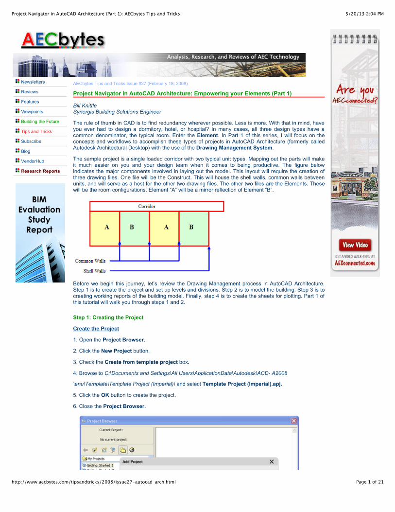
The sample project is a single loaded corridor with two typical unit types. Mapping out the parts will makeit much easier on you and your design team when it comes to being productive. The figure belowindicates the major components involved in laying out the model. This layout will require the creation ofthree drawing files. One file will be the Construct. This will house the shell walls, common walls betweenunits, and will serve as a host for the other two drawing files. The other two files are the Elements. Thesewill be the room configurations. Element “A” will be a mirror reflection of Element “B”.
Before we begin this journey, let’s review the Drawing Management process in AutoCAD Architecture.Step 1 is to create the project and set up levels and divisions. Step 2 is to model the building. Step 3 is tocreating working reports of the building model. Finally, step 4 is to create the sheets for plotting. Part 1 ofthis tutorial will walk you through steps 1 and 2.
Step 1: Creating the Project
Create the Project
1. Open the Project Browser.
2. Click the New Project button.
3. Check the Create from template project box.
4. Browse to C:\Documents and Settings\All Users\ApplicationData\Autodesk\ACD- A2008
\enu\Template\Template Project (Imperial)\ and select Template Project (Imperial).apj.
5. Click the OK button to create the project.
6. Close the Project Browser.
5/20/13 2:04 PMProject Navigator in AutoCAD Architecture (Part 1): AECbytes Tips and Tricks
Page 2 of 21http://www.aecbytes.com/tipsandtricks/2008/issue27-autocad_arch.html
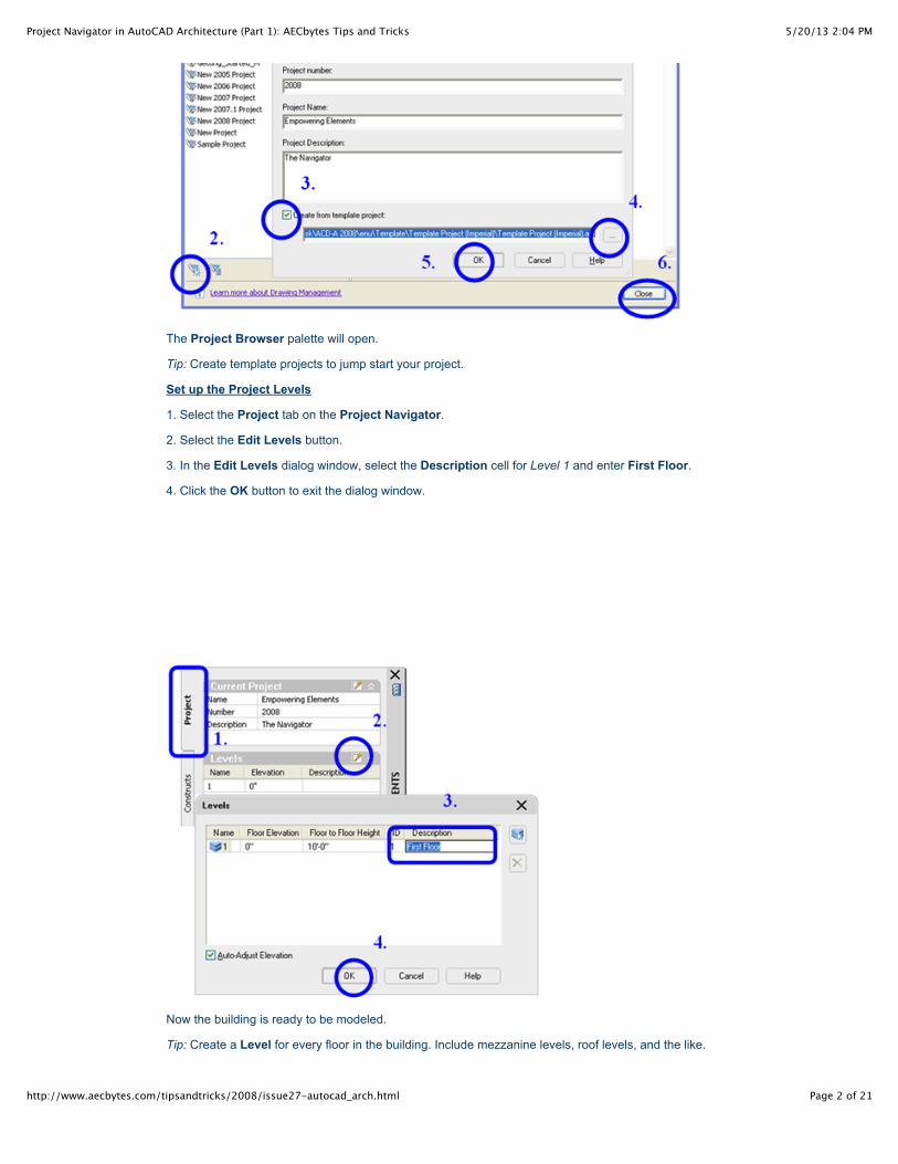
The Project Browser palette will open.
Tip: Create template projects to jump start your project.
Set up the Project Levels
1. Select the Project tab on the Project Navigator.
2. Select the Edit Levels button.
3. In the Edit Levels dialog window, select the Description cell for Level 1 and enter First Floor.
4. Click the OK button to exit the dialog window.
Now the building is ready to be modeled.
Tip: Create a Level for every floor in the building. Include mezzanine levels, roof levels, and the like.
5/20/13 2:04 PMProject Navigator in AutoCAD Architecture (Part 1): AECbytes Tips and Tricks
Page 3 of 21http://www.aecbytes.com/tipsandtricks/2008/issue27-autocad_arch.html
Step 2: Model the Building
Create a Construct assigned to the First Floor
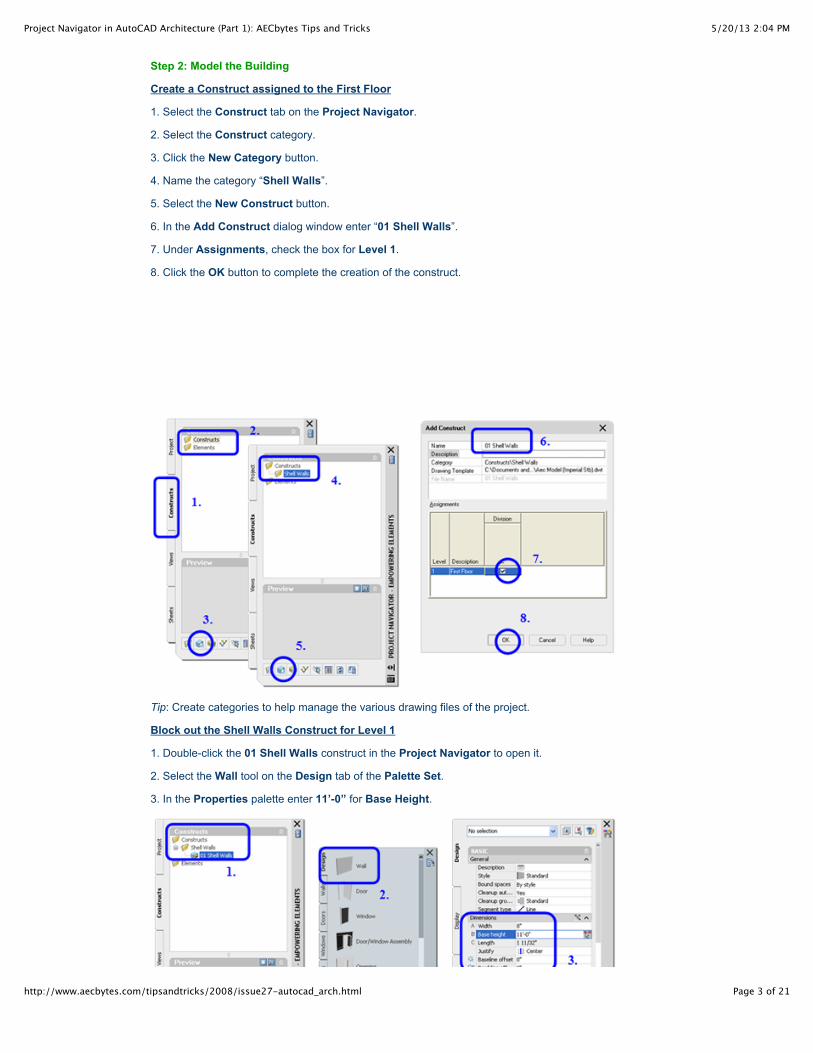
1. Select the Construct tab on the Project Navigator.
2. Select the Construct category.
3. Click the New Category button.
4. Name the category “Shell Walls”.
5. Select the New Construct button.
6. In the Add Construct dialog window enter “01 Shell Walls”.
7. Under Assignments, check the box for Level 1.
8. Click the OK button to complete the creation of the construct.
Tip: Create categories to help manage the various drawing files of the project.
Block out the Shell Walls Construct for Level 1
1. Double-click the 01 Shell Walls construct in the Project Navigator to open it.
2. Select the Wall tool on the Design tab of the Palette Set.
3. In the Properties palette enter 11’-0” for Base Height.
5/20/13 2:04 PMProject Navigator in AutoCAD Architecture (Part 1): AECbytes Tips and Tricks
Page 4 of 21http://www.aecbytes.com/tipsandtricks/2008/issue27-autocad_arch.html
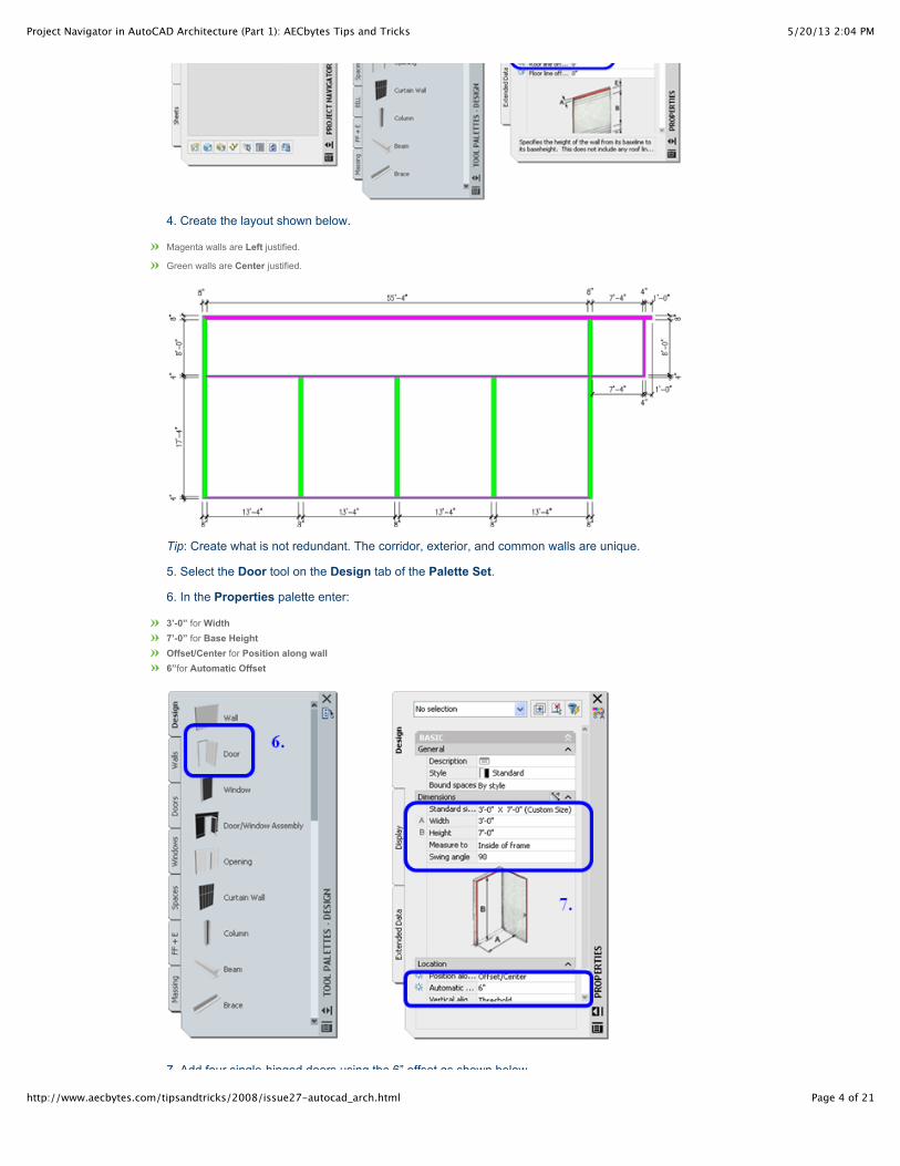
4. Create the layout shown below.
Magenta walls are Left justified.
Green walls are Center justified.
Tip: Create what is not redundant. The corridor, exterior, and common walls are unique.
5. Select the Door tool on the Design tab of the Palette Set.
6. In the Properties palette enter:
3’-0” for Width7’-0” for Base HeightOffset/Center for Position along wall6”for Automatic Offset
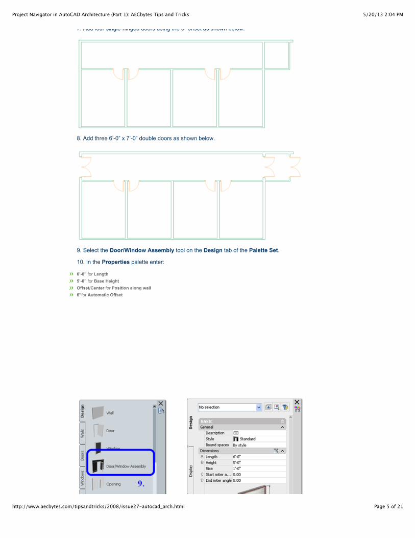
7. Add four single-hinged doors using the 6” offset as shown below.
5/20/13 2:04 PMProject Navigator in AutoCAD Architecture (Part 1): AECbytes Tips and Tricks
Page 5 of 21http://www.aecbytes.com/tipsandtricks/2008/issue27-autocad_arch.html
7. Add four single-hinged doors using the 6” offset as shown below.
8. Add three 6’-0” x 7’-0” double doors as shown below.
9. Select the Door/Window Assembly tool on the Design tab of the Palette Set.
10. In the Properties palette enter:
6’-0” for Length5’-0” for Base HeightOffset/Center for Position along wall6”for Automatic Offset
5/20/13 2:04 PMProject Navigator in AutoCAD Architecture (Part 1): AECbytes Tips and Tricks
Page 6 of 21http://www.aecbytes.com/tipsandtricks/2008/issue27-autocad_arch.html
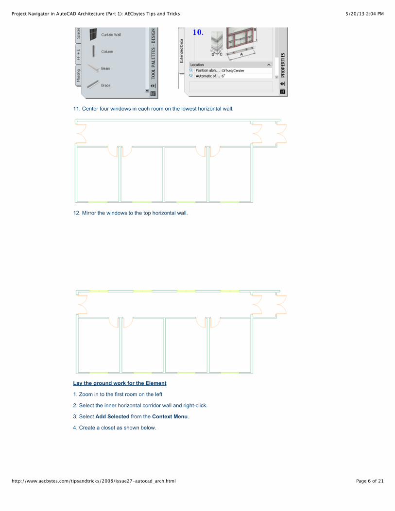
11. Center four windows in each room on the lowest horizontal wall.
12. Mirror the windows to the top horizontal wall.
Lay the ground work for the Element
1. Zoom in to the first room on the left.
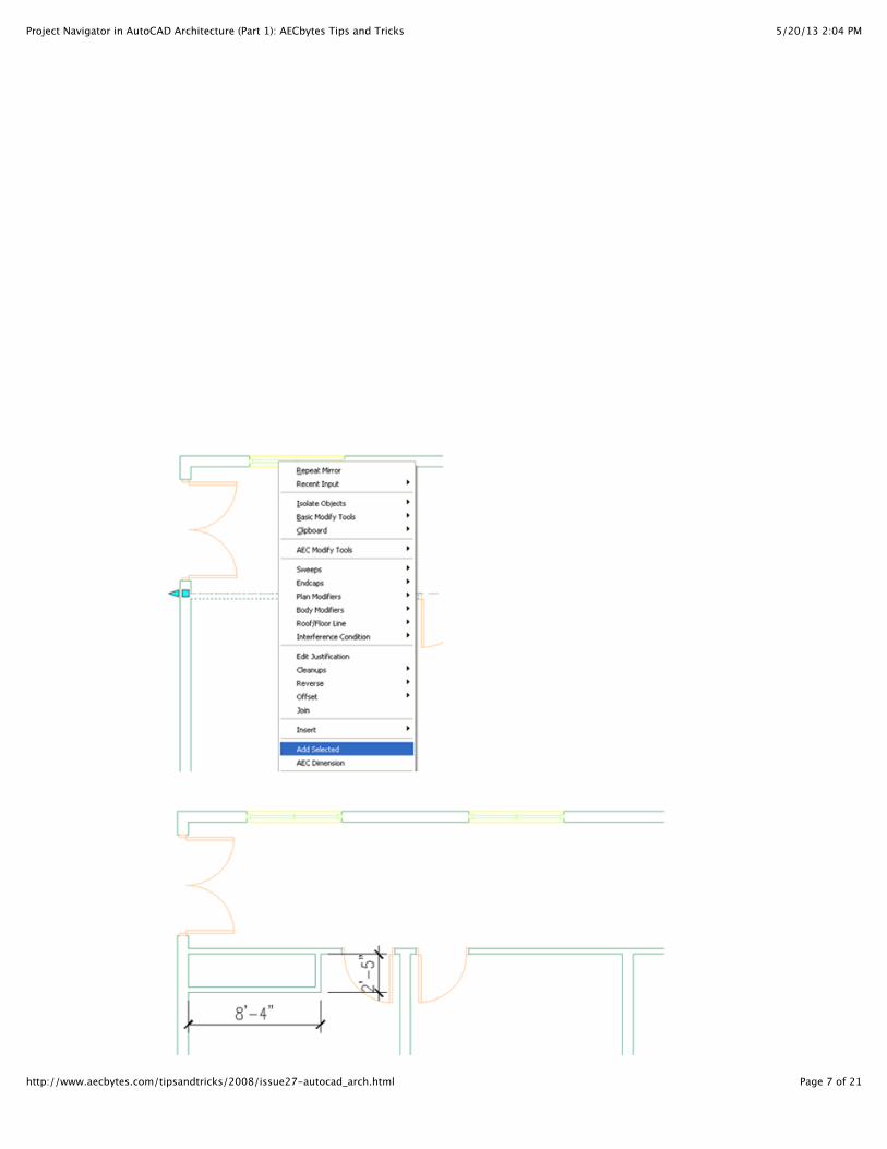
2. Select the inner horizontal corridor wall and right-click.
3. Select Add Selected from the Context Menu.
4. Create a closet as shown below.
5/20/13 2:04 PMProject Navigator in AutoCAD Architecture (Part 1): AECbytes Tips and Tricks
Page 7 of 21http://www.aecbytes.com/tipsandtricks/2008/issue27-autocad_arch.html
5/20/13 2:04 PMProject Navigator in AutoCAD Architecture (Part 1): AECbytes Tips and Tricks
Page 8 of 21http://www.aecbytes.com/tipsandtricks/2008/issue27-autocad_arch.html
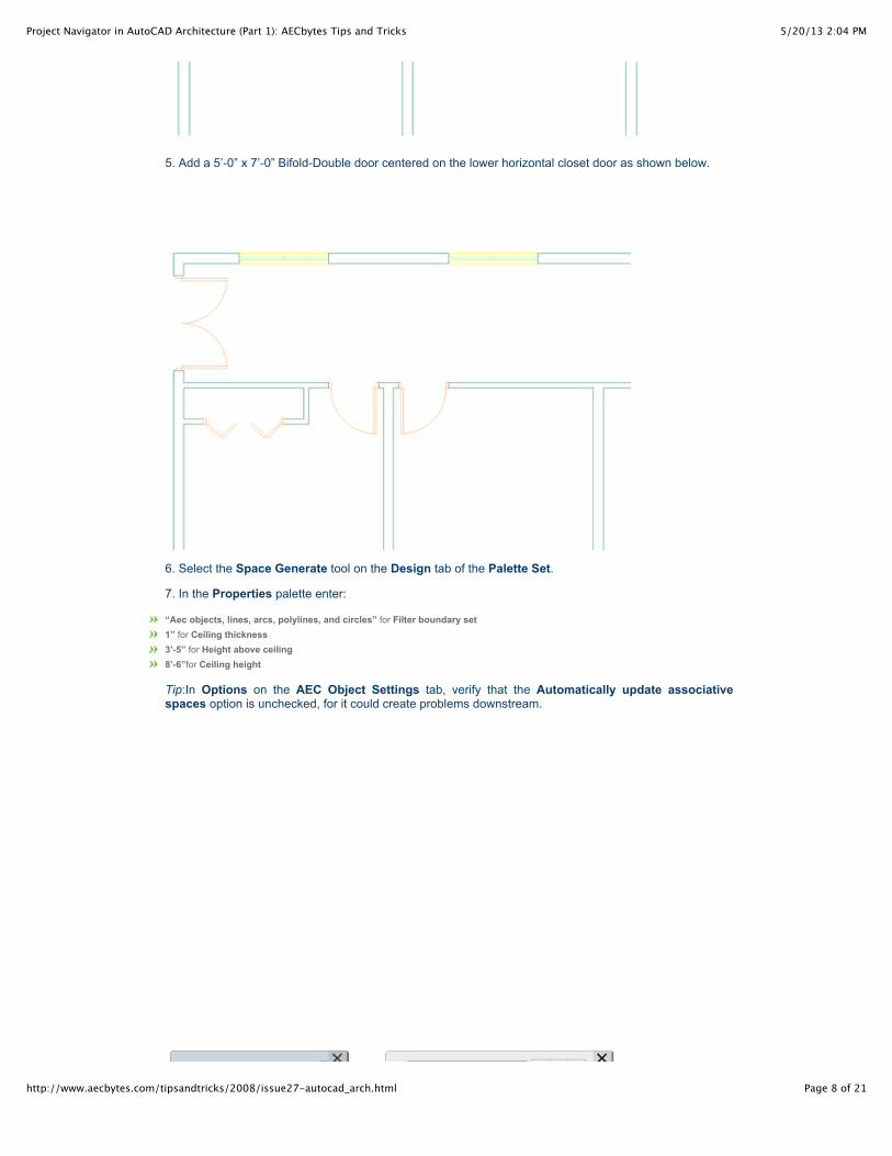
5. Add a 5’-0” x 7’-0” Bifold-Double door centered on the lower horizontal closet door as shown below.
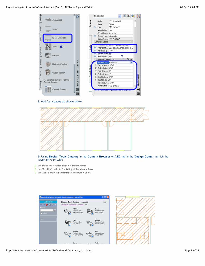
6. Select the Space Generate tool on the Design tab of the Palette Set.
7. In the Properties palette enter:
“Aec objects, lines, arcs, polylines, and circles” for Filter boundary set1” for Ceiling thickness3’-5” for Height above ceiling8’-6”for Ceiling height
Tip:In Options on the AEC Object Settings tab, verify that the Automatically update associativespaces option is unchecked, for it could create problems downstream.
5/20/13 2:04 PMProject Navigator in AutoCAD Architecture (Part 1): AECbytes Tips and Tricks
Page 9 of 21http://www.aecbytes.com/tipsandtricks/2008/issue27-autocad_arch.html
8. Add four spaces as shown below.
9. Using Design Tools Catalog in the Content Browser or AEC tab in the Design Center, furnish thelower-left room with:
two Twin beds in Furnishings > Furniture > Bedstwo 36x18 Left desks in Furnishings > Furniture > Desktwo Chair 5 chairs in Furnishings > Furniture > Chair
5/20/13 2:04 PMProject Navigator in AutoCAD Architecture (Part 1): AECbytes Tips and Tricks
Page 10 of 21http://www.aecbytes.com/tipsandtricks/2008/issue27-autocad_arch.html
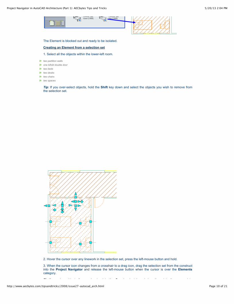
The Element is blocked out and ready to be isolated.
Creating an Element from a selection set
1. Select all the objects within the lower-left room.
two partition walls
one bifold double door
two beds
two desks
two chairs
two spaces
Tip: If you over-select objects, hold the Shift key down and select the objects you wish to remove fromthe selection set.
2. Hover the cursor over any linework in the selection set, press the left-mouse button and hold.
3. When the cursor icon changes from a crosshair to a drag icon, drag the selection set from the constructinto the Project Navigator and release the left-mouse button when the cursor is over the Elementscategory.
Tip:If you drag objects from a drawing into the Constructs tab and drop them into the appropriate
5/20/13 2:04 PMProject Navigator in AutoCAD Architecture (Part 1): AECbytes Tips and Tricks
Page 11 of 21http://www.aecbytes.com/tipsandtricks/2008/issue27-autocad_arch.html
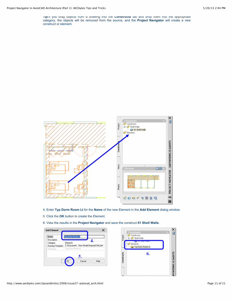
Tip:If you drag objects from a drawing into the Constructs tab and drop them into the appropriatecategory, the objects will be removed from the source, and the Project Navigator will create a newconstruct or element.
4. Enter Typ Dorm Room Lt for the Name of the new Element in the Add Element dialog window.
5. Click the OK button to create the Element.
6. View the results in the Project Navigator and save the construct 01 Shell Walls.
5/20/13 2:04 PMProject Navigator in AutoCAD Architecture (Part 1): AECbytes Tips and Tricks
Page 12 of 21http://www.aecbytes.com/tipsandtricks/2008/issue27-autocad_arch.html
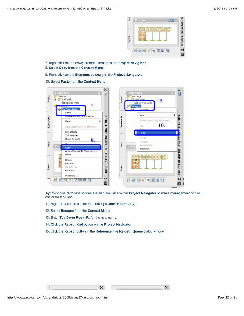
7. Right-click on the newly created element in the Project Navigator.8. Select Copy from the Context Menu.
9. Right-click on the Elements category in the Project Navigator.
10. Select Paste from the Context Menu.
Tip: Windows clipboard options are also available within Project Navigator to make management of fileseasier for the user.
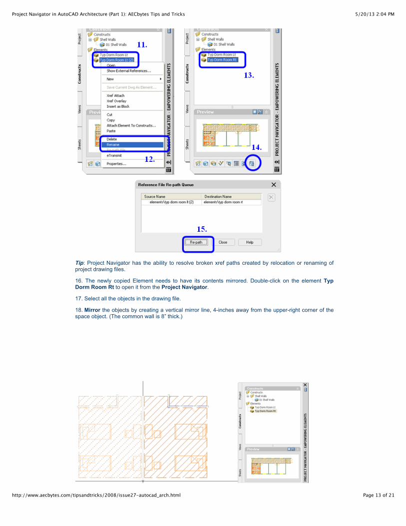
11. Right-click on the copied Element Typ Dorm Room Lt (2).
12. Select Rename from the Context Menu.
13. Enter Typ Dorm Room Rt for the new name.
14. Click the Repath Xref button on the Project Navigator.
15. Click the Repath button in the Reference File Re-path Queue dialog window.
5/20/13 2:04 PMProject Navigator in AutoCAD Architecture (Part 1): AECbytes Tips and Tricks
Page 13 of 21http://www.aecbytes.com/tipsandtricks/2008/issue27-autocad_arch.html
Tip: Project Navigator has the ability to resolve broken xref paths created by relocation or renaming ofproject drawing files.
16. The newly copied Element needs to have its contents mirrored. Double-click on the element TypDorm Room Rt to open it from the Project Navigator.
17. Select all the objects in the drawing file.
18. Mirror the objects by creating a vertical mirror line, 4-inches away from the upper-right corner of thespace object. (The common wall is 8” thick.)
5/20/13 2:04 PMProject Navigator in AutoCAD Architecture (Part 1): AECbytes Tips and Tricks
Page 14 of 21http://www.aecbytes.com/tipsandtricks/2008/issue27-autocad_arch.html
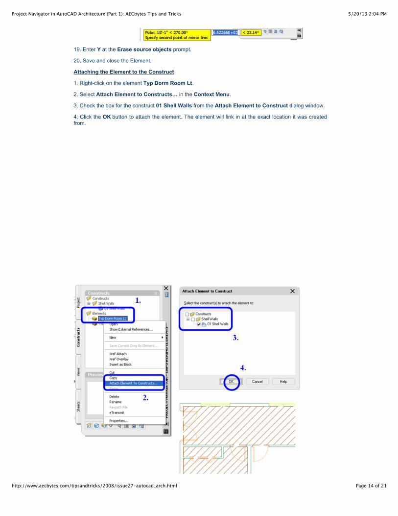
19. Enter Y at the Erase source objects prompt.
20. Save and close the Element.
Attaching the Element to the Construct
1. Right-click on the element Typ Dorm Room Lt.
2. Select Attach Element to Constructs… in the Context Menu.
3. Check the box for the construct 01 Shell Walls from the Attach Element to Construct dialog window.
4. Click the OK button to attach the element. The element will link in at the exact location it was createdfrom.
5/20/13 2:04 PMProject Navigator in AutoCAD Architecture (Part 1): AECbytes Tips and Tricks
Page 15 of 21http://www.aecbytes.com/tipsandtricks/2008/issue27-autocad_arch.html
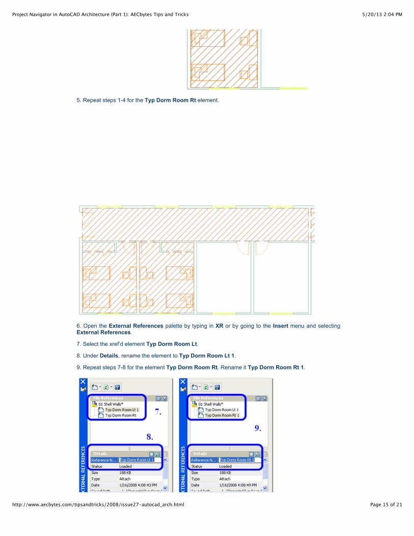
5. Repeat steps 1-4 for the Typ Dorm Room Rt element.
6. Open the External References palette by typing in XR or by going to the Insert menu and selectingExternal References.
7. Select the xref’d element Typ Dorm Room Lt.
8. Under Details, rename the element to Typ Dorm Room Lt 1.
9. Repeat steps 7-8 for the element Typ Dorm Room Rt. Rename it Typ Dorm Room Rt 1.

5/20/13 2:04 PMProject Navigator in AutoCAD Architecture (Part 1): AECbytes Tips and Tricks
Page 16 of 21http://www.aecbytes.com/tipsandtricks/2008/issue27-autocad_arch.html
Tip: By default, an element can only be attached once. Mirror copies or copies of the element will fail tohave their walls cleaned up. Therefore, to attach multiple elements, the previous one must be renamed.
10. Right-click on the element Typ Dorm Room Lt.
11. Select Xref Attach from the Context Menu.
12. Repeat steps 7-8 for the element Typ Dorm Room Lt.13. Rename it Typ Dorm Room Lt 3.
Tip: The Element will be attached as a new instance. It will also be inserted at the Element’s origin point.Therefore, it must be moved.
14. Select the element in the first room.
15. Use the Move command to relocate it to the third room.
16. Repeat steps 10-15 to attach the element Typ Dorm Room Rt, rename it to Typ Dorm Room Rt 4,and move it to the last room.
5/20/13 2:04 PMProject Navigator in AutoCAD Architecture (Part 1): AECbytes Tips and Tricks
Page 17 of 21http://www.aecbytes.com/tipsandtricks/2008/issue27-autocad_arch.html
You have successfully created a floor plan. Bear in mind that all modifications to a room layout must bemade back in the Element drawing. Any changes will then be propagated to the Constructs in which it isattached via the external reference link. With one floor completed, you can move on to create theadditional floors of the building model. Remember, less is more. Project Navigator’s productivity toolsmake it fairly easy to complete this process.
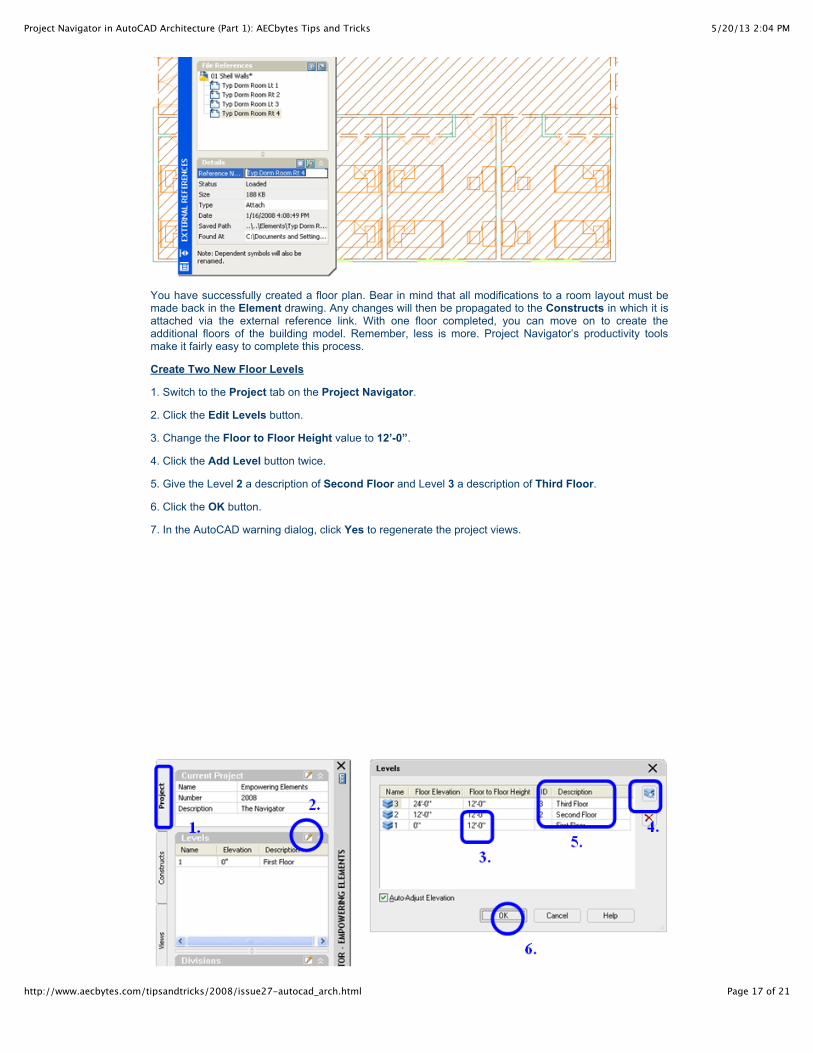
Create Two New Floor Levels
1. Switch to the Project tab on the Project Navigator.
2. Click the Edit Levels button.
3. Change the Floor to Floor Height value to 12’-0”.
4. Click the Add Level button twice.
5. Give the Level 2 a description of Second Floor and Level 3 a description of Third Floor.
6. Click the OK button.
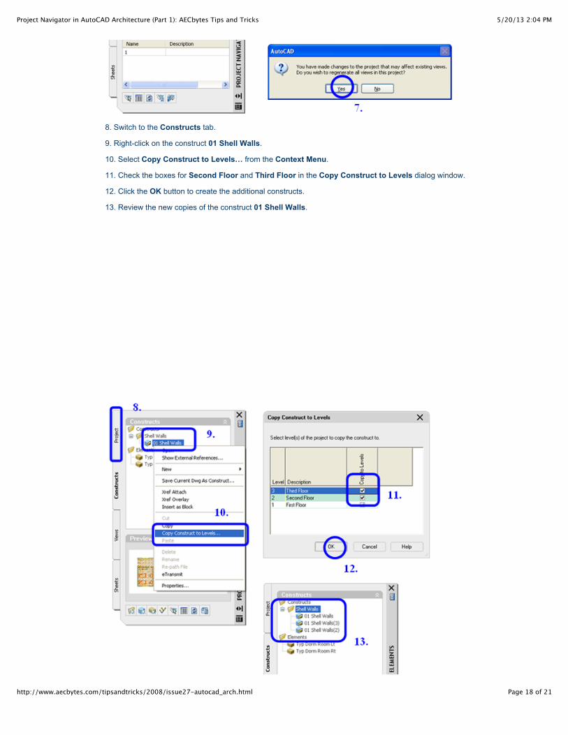
7. In the AutoCAD warning dialog, click Yes to regenerate the project views.
5/20/13 2:04 PMProject Navigator in AutoCAD Architecture (Part 1): AECbytes Tips and Tricks
Page 18 of 21http://www.aecbytes.com/tipsandtricks/2008/issue27-autocad_arch.html
8. Switch to the Constructs tab.
9. Right-click on the construct 01 Shell Walls.
10. Select Copy Construct to Levels… from the Context Menu.
11. Check the boxes for Second Floor and Third Floor in the Copy Construct to Levels dialog window.
12. Click the OK button to create the additional constructs.
13. Review the new copies of the construct 01 Shell Walls.
5/20/13 2:04 PMProject Navigator in AutoCAD Architecture (Part 1): AECbytes Tips and Tricks
Page 19 of 21http://www.aecbytes.com/tipsandtricks/2008/issue27-autocad_arch.html
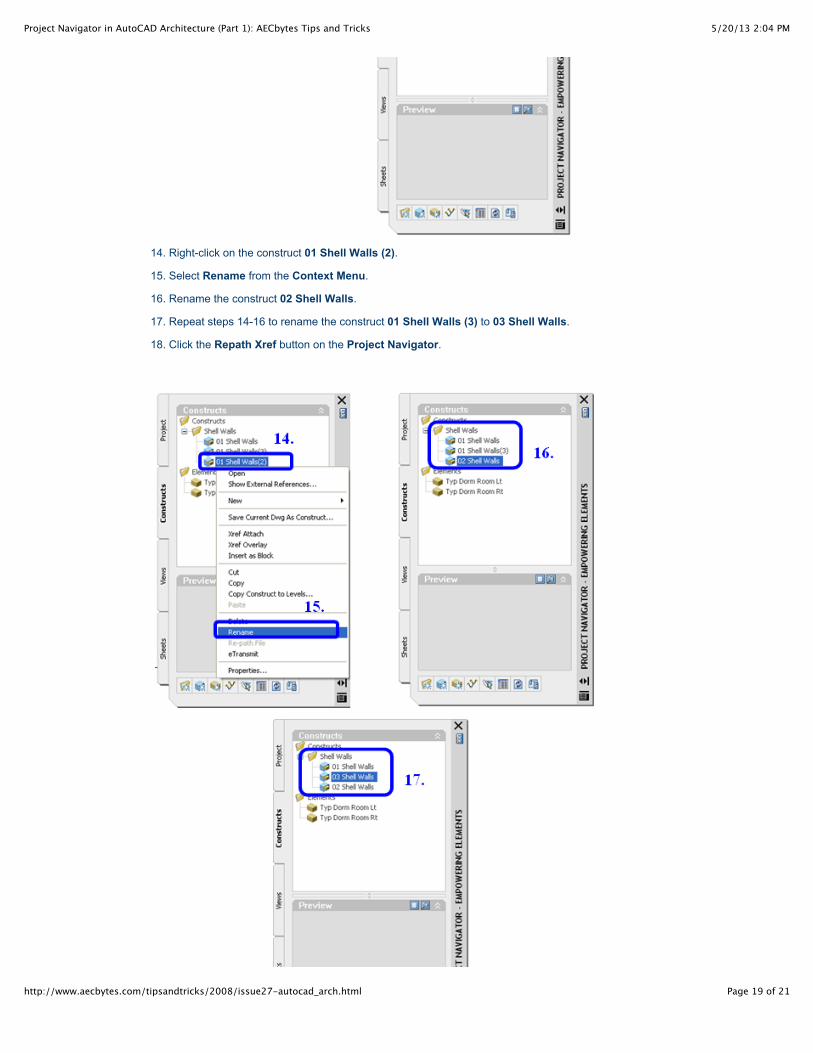
14. Right-click on the construct 01 Shell Walls (2).
15. Select Rename from the Context Menu.
16. Rename the construct 02 Shell Walls.
17. Repeat steps 14-16 to rename the construct 01 Shell Walls (3) to 03 Shell Walls.
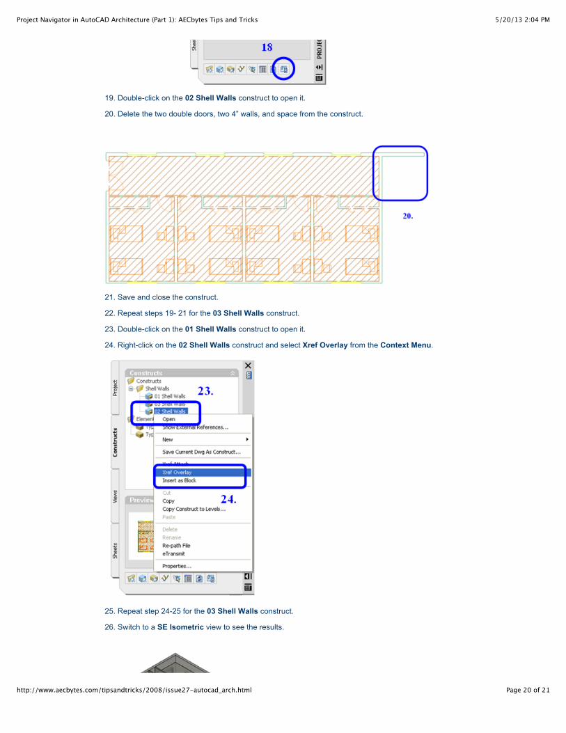
18. Click the Repath Xref button on the Project Navigator.
5/20/13 2:04 PMProject Navigator in AutoCAD Architecture (Part 1): AECbytes Tips and Tricks
Page 20 of 21http://www.aecbytes.com/tipsandtricks/2008/issue27-autocad_arch.html
19. Double-click on the 02 Shell Walls construct to open it.
20. Delete the two double doors, two 4” walls, and space from the construct.
21. Save and close the construct.
22. Repeat steps 19- 21 for the 03 Shell Walls construct.
23. Double-click on the 01 Shell Walls construct to open it.
24. Right-click on the 02 Shell Walls construct and select Xref Overlay from the Context Menu.
25. Repeat step 24-25 for the 03 Shell Walls construct.
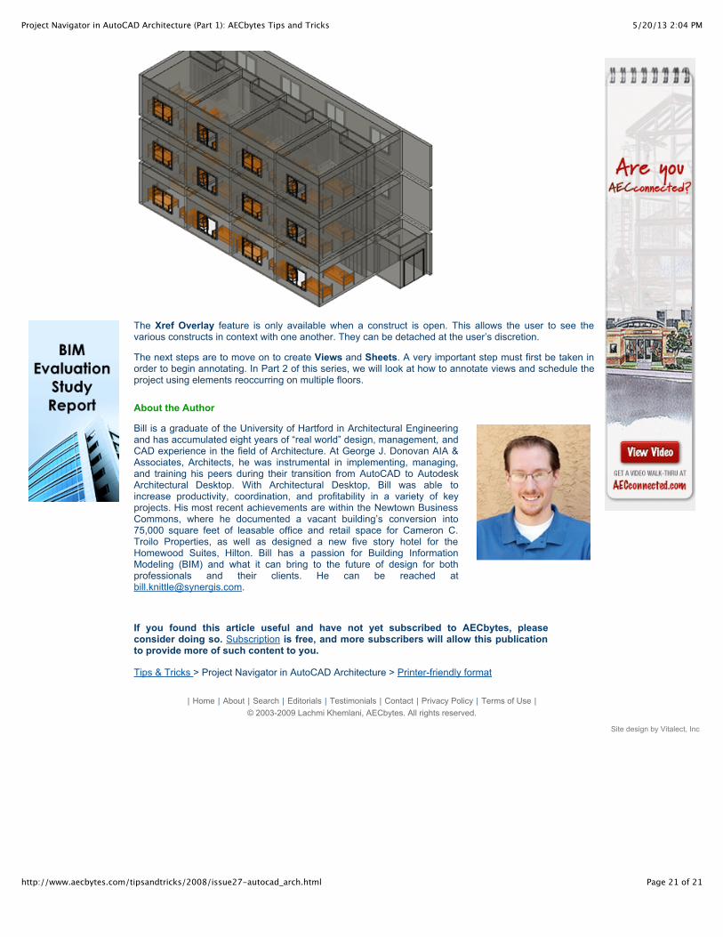
26. Switch to a SE Isometric view to see the results.
5/20/13 2:04 PMProject Navigator in AutoCAD Architecture (Part 1): AECbytes Tips and Tricks
Page 21 of 21http://www.aecbytes.com/tipsandtricks/2008/issue27-autocad_arch.html
The Xref Overlay feature is only available when a construct is open. This allows the user to see thevarious constructs in context with one another. They can be detached at the user’s discretion.
The next steps are to move on to create Views and Sheets. A very important step must first be taken inorder to begin annotating. In Part 2 of this series, we will look at how to annotate views and schedule theproject using elements reoccurring on multiple floors.
About the Author
Bill is a graduate of the University of Hartford in Architectural Engineeringand has accumulated eight years of “real world” design, management, andCAD experience in the field of Architecture. At George J. Donovan AIA &Associates, Architects, he was instrumental in implementing, managing,and training his peers during their transition from AutoCAD to AutodeskArchitectural Desktop. With Architectural Desktop, Bill was able toincrease productivity, coordination, and profitability in a variety of keyprojects. His most recent achievements are within the Newtown BusinessCommons, where he documented a vacant building’s conversion into75,000 square feet of leasable office and retail space for Cameron C.Troilo Properties, as well as designed a new five story hotel for theHomewood Suites, Hilton. Bill has a passion for Building InformationModeling (BIM) and what it can bring to the future of design for bothprofessionals and their clients. He can be reached [email protected].
If you found this article useful and have not yet subscribed to AECbytes, pleaseconsider doing so. Subscription is free, and more subscribers will allow this publicationto provide more of such content to you.
Tips & Tricks > Project Navigator in AutoCAD Architecture > Printer-friendly format
| Home | About | Search | Editorials | Testimonials | Contact | Privacy Policy | Terms of Use |© 2003-2009 Lachmi Khemlani, AECbytes. All rights reserved.
Site design by Vitalect, Inc