project specifications - california
TRANSCRIPT

For questions or comments pertaining to this report, contact Enovity Inc. Reproduction or distribution of the whole, or any part of the contents of, this document without permission of the Administrative Offices of the Courts is prohibited. Neither Enovity nor any of its employees makes any warranty, express or implied, or assumes any legal liability of responsibility for the accuracy, completeness, or usefulness of any data, information, method, product or process disclosed in this document, or represents that its use will not infringe any privately-owned rights, including but not limited to, patents, trademarks or copyrights.
Project Specifications
March 3, 2014
Prepared By:
26 Executive Park, Suite 170, Irvine, CA 92614
(888) 900-9978 x2700
PROJECT#: 0413-019
HVAC and BAS Upgrade Project
George McDonald Hall of Justice 2233 Shore Line Drive
Alameda, CA 94501 Building No.: 01-F1
ATTACHMENT A

For questions or comments pertaining to this report, contact Enovity Inc. Reproduction or distribution of the whole, or any part of the contents of, this document without permission of the Administrative Offices of the Courts is prohibited. Neither Enovity nor any of its employees makes any warranty, express or implied, or assumes any legal liability of responsibility for the accuracy, completeness, or usefulness of any data, information, method, product or process disclosed in this document, or represents that its use will not infringe any privately-owned rights, including but not limited to, patents, trademarks or copyrights.
This page is left intentionally blank for double-sided printing.
ATTACHMENT A

Judicial Council of California - Administrative Office of the Courts HVAC AND BAS UPGRADE PROJECT Office of Court Construction and Management GEORGE MCDONALD HALL OF JUSTICE Facilities Management / Design and Construction Services (Rev.0)
ENOVITY, INC. TABLE OF CONTENTS Project#: 0413-019 00 01 10 - 1
SECTION 00 01 10 TABLE OF CONTENTS
00 00 00 PROCUREMENT AND CONTRACTING REQUIREMENTS 00 01 10 TABLE OF CONTENTS 00 20 00 INSTRUCTIONS FOR PROCUREMENT
01 00 00 GENERAL REQUIREMENTS 01 00 00 GENERAL REQUIREMENTS
01 10 00 SUMMARY 01 11 00 SUMMARY OF WORK
01 70 00 EXECUTION AND CLOSEOUT REQUIREMENTS 01 78 23 O&M DATA 01 78 36 WARRANTIES 01 79 00 DEMONSTRATION AND TRAINING
23 00 00 HEATING, VENTILATING, AND AIR-CONDITIONING (HVAC) 23 05 48 SIESMIC FOR HVAC 23 05 93 TESTING, ADJUSTING AND BALANCING FOR HVAC (TAB) 23 08 00 COMMISSIONING OF HVAC 23 09 13 INSTRUMENTATION AND CONTROL FIELD DEVICES DDC 23 09 23 DDC SYSTEM FOR HVAC 23 09 27 FIELD PANELS 23 09 36 VARIABLE FREQUENCY DRIVES (REFERENCE FOR ADD ALTERNATE #2) 23 09 93 SEQUENCE OF OPERATIONS 23 30 00 HVAC AIR DISTRIBUTION 23 73 00 CENTRAL STATION AHU
26 00 00 ELECTRICAL 26 05 00 COMMON WORK FOR ELECTRICAL 26 05 19 LOW VOLTAGE ELECTRICAL POWER CONDUCTORS AND CABLES 26 05 26 GROUNDING AND BONDING FOR ELECTRICAL SYSTEMS 26 05 29 HANGAR AND SUPPORTS FOR ELECTRICAL SYSTEMS 26 05 33 RACEWAY AND BOXES FOR ELECTRICAL SYSTEMS 26 05 53 IDENTIFICATION FOR ELECTRICAL SYSTEMS 26 09 23 LIGHTING CONTROL DEVICES
EXHIBITS EXHIBIT A MINIMUM SUGGESTED BAS POINTS LIST EXHIBIT B MINIMUM GRAPGHICS DESIGN FOR THE AOC
ATTACHMENT A

Judicial Council of California - Administrative Office of the Courts HVAC AND BAS UPGRADE PROJECT Office of Court Construction and Management GEORGE MCDONALD HALL OF JUSTICE Facilities Management / Design and Construction Services (Rev.0)
ENOVITY, INC. INSTRUCTIONS FOR PROCUREMENT Project#: 0413-019 00 20 00 - 1
SECTION 00 20 00 INSTRUCTIONS FOR PROCUREMENT
PART 1 GENERAL
1.01 INSTRUCTIONS TO BIDDERS A. Bidder Requirements: All bidders must be licensed contractors in the State of California
regularly engaged in the type of work described herein. B. Project Title: George McDonald HOJ BAS Upgrade C. Proposal Submittal Format
Email Instructions. a. Bid Format. Bids shall be submitted in Adobe Acrobat™ (.pdf) format as one
complete file. Naming convention shall be as follows: 1) Naming Convention Structure: “GMcD-BAS-HVACPpsl-Company.pdf”.
Bidder shall replace “Company” portion of the naming convention with their abbreviated company name (limit to 8 characters). Any proposal revisions shall add “R#” immediately following company name with”#” representing the revision number.
2) Base Bid plus Bid Alternate Structure. Provide Base Bid pricing, with each Bid Alternate on each line thereafter. Base Bid $ Bid Alternate #1 $ Unit Price #1 $ Unit Price #2 $ Unit Price #3 $ Unit Price #4 $ Unit Price #5 $ Unit Price #6 $
b. Bid Submittal. Proposals shall be emailed to the AOC Project Manager at the
following: [email protected]
D. All inquires for information should be directed to the AOC Project Manager: Glenn Mantoani [email protected]
PART 2 PRODUCT – NOT USED PART 3 EXECUTION
3.01 PRE-BID MEETING A. A MANDATORY job walk will be held at the project site, 2233 Shore Line Drive, Alameda
CA 94501 (meet outside of main building entry), as outlined above.
ATTACHMENT A

Judicial Council of California - Administrative Office of the Courts HVAC AND BAS UPGRADE PROJECT Office of Court Construction and Management GEORGE MCDONALD HALL OF JUSTICE Facilities Management / Design and Construction Services (Rev.0)
ENOVITY, INC. INSTRUCTIONS FOR PROCUREMENT Project#: 0413-019 00 20 00 - 2
3.02 QUESTIONS A. Questions must be provided in writing and submitted by the date in the above section. A
response will be submitted back to the contractor in writing within 4 working days of the Questions Due date.
B. Parking is available in the lot on site.
3.03 MECHANICAL CONTRACTOR QUALIFICATIONS A. Work shall be directed by the Construction Manager and coordinated by the Contractor. B. The Contractor shall engineer, install, test and calibrate all systems associated with the scope
of work. C. Contractor shall provide a final approved drawings package stamped by the mechanical
engineer of record. D. The Contractor shall have in place a support facility located within 150 miles of the project
site with technical staff and all necessary test and diagnostic equipment. Factory trained technicians shall provide instruction, routine maintenance, and emergency service within 24 hours upon receipt of request.
E. The Contractor must be regularly engaged in the service and installation of HVAC mechanical systems as specified herein. In addition, the contractor shall employ and assign to this project, engineers and technicians that are regularly engaged in the service and installation of HVAC systems as specified herein.
F. Contractor must have no less than three (3) similar demonstration projects, which have a similar scope of work.
3.04 ELECTRICAL CONTRACTOR QUALIFICATIONS A. Work shall be directed by the Construction Manager and coordinated by the Contractor. B. The Contractor shall engineer, install, test and calibrate all systems associated with the scope
of work. C. Contractor shall provide a final approved drawings package stamped by the electrical
engineer of record. D. The Contractor shall have in place a support facility located within 150 miles of the project
site with technical staff and all necessary test and diagnostic equipment. Factory trained technicians shall provide instruction, routine maintenance, and emergency service within 24 hours upon receipt of request.
E. The Contractor must be regularly engaged in the service and installation of electrical systems as specified herein. In addition, the contractor shall employ and assign to this project, engineers and technicians that are regularly engaged in the service and installation of electrical systems as specified herein.
F. Contractor must have no less than three (3) similar demonstration projects, which have a similar scope of work.
3.05 CONTROLS CONTRACTOR QUALIFICATIONS A. Work shall be directed by the Construction Manager and coordinated by the Contractor. B. The Contractor shall engineer, install, test and calibrate all systems associated with the scope
of work. C. Contractor shall provide a final approved drawings package stamped by the mechanical
engineer of record.
ATTACHMENT A

Judicial Council of California - Administrative Office of the Courts HVAC AND BAS UPGRADE PROJECT Office of Court Construction and Management GEORGE MCDONALD HALL OF JUSTICE Facilities Management / Design and Construction Services (Rev.0)
ENOVITY, INC. INSTRUCTIONS FOR PROCUREMENT Project#: 0413-019 00 20 00 - 3
D. The Contractor shall have in place a support facility located within 150 miles of the project site with technical staff and all necessary test and diagnostic equipment. Factory trained technicians shall provide instruction, routine maintenance, and emergency service within 24 hours upon receipt of request.
E. The Contractor must be regularly engaged in the service and installation of building automation systems (BAS) as specified herein. In addition, the contractor shall employ and assign to this project, engineers and technicians that are regularly engaged in the service and installation of BAS control systems as specified herein.
F. Contractor must have no less than three (3) similar demonstration projects, which have a similar scope of work.
3.06 CONTRACTOR PROPOSALS A. Work shall be performed as a design-build fixed price project. Contractor shall visit site prior
to submitting a bid proposal. Ascertain and check all conditions and take all measurements that may effect the work. Drawings provided are to be used at Contractor’s risk; drawings are schematic and may or may not be drawn accurately. No allowance shall subsequently be made for any additional expenses or claims due to the failure or neglect under this section to make such examination, including examination of restricted working conditions or such other difficulties that can be visually observed during site visit.
B. By submitting a price, Contractor guarantees that the proposal is complete, except where specific exceptions are provided herein or clearly noted in the Contractor’s proposal.
C. Proposals shall include: 1) Reference to specific project. 2) General description of scope of work and reference to the specification set 3) Proposed location of equipment outlined in the Scope of Work 4) Preliminary schedule based upon anticipated date of contract award 5) Construction plan of installation for major equipment retrofit, including the
estimated maximum downtime for the equipment being replaced. Describe the estimated number of shutdowns needed (including time of day and week) for all systems.
6) List of inclusions 7) Clarifications and exclusions 8) All labor required to complete the above scope of work during unoccupied times
as applicable. 9) List of project team members and their qualifications including direct experience
related to their project role. 10) List of subcontractors, their project team, their project role, and their
qualifications. 11) Estimated maximum downtime of equipment and potential impact to court
operations. 12) Proposed Fixed Price Fee, as follows
a. Base Scope of Work b. Base Scope plus add alternate(s)
ATTACHMENT A

Judicial Council of California - Administrative Office of the Courts HVAC AND BAS UPGRADE PROJECT Office of Court Construction and Management GEORGE MCDONALD HALL OF JUSTICE Facilities Management / Design and Construction Services (Rev.0)
ENOVITY, INC. INSTRUCTIONS FOR PROCUREMENT Project#: 0413-019 00 20 00 - 4
c. Base scope plus Unit Pricing as indicated 13) List of (3) representative sample HVAC/BAS projects including client name,
company, email, and phone number.
END OF SECTION 00 20 00
ATTACHMENT A

Judicial Council of California - Administrative Office of the Courts HVAC AND BAS UPGRADE PROJECT Office of Court Construction and Management GEORGE MCDONALD HALL OF JUSTICE Facilities Management / Design and Construction Services (Rev.0)
ENOVITY, INC. GENERAL REQUIREMENTS Project#: 0413-019 01 00 00 - 1
SECTION 01 00 00 GENERAL REQUIREMENTS
PART 1 GENERAL
1.01 EXISTING CONDITIONS A. Contractor is responsible for examining existing site conditions and equipment conditions.
Specification documents provide performance requirements. It is the Contractor’s responsibility to engineer, permit, provide, and install a fully functioning system. Equipment selection shall be the Contractor’s responsibility with the approval of the Owner and Owner’s Representatives.
B. Parts of the roof and floors are known to contain non-fryable asbestos. The Contractor shall notify the Owner if work potentially requires disturbing the asbestos containing material (ACM). All ACM abatement shall be the responsibility of the AOC under separate contract.
1.02 WORK INCLUDED: A. Demolition; all old equipment that is replaced shall be removed from the site and disposed of
in accordance with local regulations. The Owner shall have first right of salvage for removed equipment.
B. Rigging C. New equipment D. Temporarily removing and repairing doors, walls, ceilings, or roof sections for access as
required E. Seismic restraints F. Electrical power wiring, disconnects, etc. for new equipment G. Direct Digital Controls (DDC)/Building Automation System (BAS) H. Test, Adjust, and Balance (TAB) I. Operator training J. All required permits and associated fees K. Commissioning of the new BAS controls
1.03 REFERENCE STANDARDS: A. Requirements of Regulatory Agencies:
1. Nothing in drawings or specifications shall be construed to permit work not conforming to applicable codes, ordinances, rules, regulations.
2. When drawings or specifications exceed requirements of applicable codes, ordinances, rules and regulations, comply with documents establishing the more stringent requirement.
3. Applicable codes include the current version of those listed below, in addition to others specified in individual sections:
4. DOSH – The Division of Occupational Safety and Health, better known as Cal/OSHA 5. IMC -International Mechanical Code 6. IPC - International Plumbing Code
ATTACHMENT A

Judicial Council of California - Administrative Office of the Courts HVAC AND BAS UPGRADE PROJECT Office of Court Construction and Management GEORGE MCDONALD HALL OF JUSTICE Facilities Management / Design and Construction Services (Rev.0)
ENOVITY, INC. GENERAL REQUIREMENTS Project#: 0413-019 01 00 00 - 2
7. NFPA - National Fire Protection Association 8. NEC - National Electrical Code 9. If any of above requirements is in conflict with one another, or with Specifications'
requirements, the most stringent requirement shall govern. Where codes are silent on an issue, NFPA Standards shall apply.
B. Published specifications, standards, tests or recommended method of trade, industry or governmental organizations as listed below apply to all work in this Section: 1. AABC - Associated Air Balance Council 2. ADC - Air Diffuser Balance Council 3. AMCA - Air Moving and Conditioning Association 4. ANSI - American National Standards Institute 5. ARI - Air Conditioning and Refrigeration Institute 6. ASHRAE ~ American Society of Heating, Refrigeration and Air Conditioning Engineers 7. ASME - American Society of Mechanical Engineers 8. ASTM - American Society for Testing and Materials 9. ASPE – American Society for Plumbing Engineers 10. CEC – Title 24 11. ETL - Intertek Semko (Formerly Electrical Testing Laboratories) 12. IEEE -Institute of Electrical and Electronic Engineers 13. NEMA - National Electrical Manufacturer's Association 14. NFPA - National Fire Protection Association 15. NUSIG - National Uniform Seismic Installation Guidelines 16. SMACNA - Sheet Metal and Air Conditioning Contractors National Association 17. UL - Underwriters' Laboratories.
C. Industry standards and manufacturers' recommendations, diagrams or requirements shall be strictly adhered to for installation of materials and equipment.
1.04 QUALITY ASSURANCE: A. All equipment and accessories to be the product of a manufacturer regularly engaged in its
manufacture. B. All items of a given type shall be the products of same manufacturer. C. Supply all equipment and accessories new and free from defects. D. Supply all equipment and accessories in compliance with the applicable standards listed in
Paragraph 1.03-B with all applicable national, state and local codes.
1.05 DEFINITIONS: A. Definitions of terms used in this section may differ from those given in general and
supplementary conditions and take precedence over them.
ATTACHMENT A

Judicial Council of California - Administrative Office of the Courts HVAC AND BAS UPGRADE PROJECT Office of Court Construction and Management GEORGE MCDONALD HALL OF JUSTICE Facilities Management / Design and Construction Services (Rev.0)
ENOVITY, INC. GENERAL REQUIREMENTS Project#: 0413-019 01 00 00 - 3
B. "Provide": to supply, install and connect up complete and ready safe and regular operation of particular work referred to unless specifically noted.
C. "Install": to erect, mount and connect complete with related accessories. D. "Supply": to purchase, procure, acquire and deliver complete with related accessories. E. "Work": labor, materials, equipment, apparatus, controls, accessories, and other items
required for proper and complete installation. F. "Piping": pipe, tube, fittings, flanges, valves, controls, strainers, hangers, supports, unions,
traps, drains, insulation, and related items. G. "Wiring": raceway, fittings, wire, boxes and related items. H. "Concealed": embedded in masonry or other construction, installed in furred spaces, within
double partitions or hung ceilings, in trenches, in crawl spaces, or in enclosures. I. "Exposed": not installed underground or "concealed" as defined above. J. "Indicated," "shown" or "noted": as indicated, shown, or noted on drawings or specifications. K. "Similar" or "equal": of base bid manufacture, equal in materials, weight, size, design, and
efficiency of specified product, conforming to PART 2 Products. L. "Reviewed," "satisfactory," or "directed": as reviewed, satisfactory, or directed by or to
Owner’s Representative. M. "Motor Controllers": manual or magnetic starters (with or without switches), individual
pushbuttons or hand-off-automatic (HOA) switches controlling the operation of motors. N. "Control or Actuating Devices": automatic sensing and switching devices such as
thermostats, pressure, float, electro-pneumatic switches and electrodes controlling operation of equipment
PART 2 PRODUCTS – NOT USED
PART 3 EXECUTION
3.01 WORK REQUIREMENTS AND RESPONSIBILITIES A. Definitions
1. BAS: Building Automation System 2. DCU: Digital Control Unit 3. DDC: Direct Digital Control 4. HMI: Human Machine Interface 5. LAN: Local Area Network 6. OWS: Operator Workstation
B. Owner Responsibilities 1. Asbestos abatement shall be performed as needed for all areas of work under a separate
contract prior to the commencement of this project work. The Contractor shall notify the Owner in writing if any abatement is required.
C. Construction Manager Responsibilities (CM) 1. Bids. CM shall request and obtain all Subcontractor bids and present them to the Owner
and the Owner’s representatives for review prior to commencement of any work.
ATTACHMENT A
Judicial Council of California - Administrative Office of the Courts HVAC AND BAS UPGRADE PROJECT Office of Court Construction and Management GEORGE MCDONALD HALL OF JUSTICE Facilities Management / Design and Construction Services (Rev.0)
ENOVITY, INC. GENERAL REQUIREMENTS Project#: 0413-019 01 00 00 - 4
2. Commissioning Support. CM shall designate one person as the Commissioning Coordinator (CxC) to interface with the Commissioning Authority (CxA) throughout the project.
3. Schedule. CM shall construct and maintain a project schedule and communicate the progress of the project with the CxA and/or the Owner.
4. Kick-off Meeting. A coordination meeting with the Construction Manager, Owner Service Provider, Commissioning Authority, and Owner representatives shall take place prior to commencement of any work.
D. Contractor(s) Responsibilities 1. Cleaning:
a. Thoroughly clean all equipment, etc. free of dust, scale, filings, plaster, grease, oil, paint and other construction debris.
b. All areas where contractor is working including mechanical and electrical rooms must be left clean and free of debris after every shift.
2. General. Contractor(s) shall provide design, submittals, materials, installation and start-up of equipment listed in representative line items in Section 01 11 00 – Summary of Work.
3. Working Conditions. Portions of the work can be performed during normal working hours (6.00 AM to 6.00 PM), but the contractor shall perform the work such that none of the controlled equipment is unavailable during their work. If off-hour work is required, the contractor shall schedule employees in a shift manner in an effort to eliminate overtime.
4. Commissioning. Completely install and thoroughly inspect, test, and document the commissioning of all systems and equipment as directed by the CxA. The contractor shall provide a dependable and fully functional system that operates properly and efficiently. Reference Section 23 08 05 for complete Commissioning guidelines and responsibilities.
3.02 SUBMITTALS: A. Schedule:
1. Product data, construction drawings, and shop drawings: Allow 10 working days for approval, unless AOC agrees to accelerated schedule.
2. Testing, Adjusting, and Balancing Procedures: Submit at least 30 days prior to performing any TAB work.
3. Operations and Maintenance Manuals: Submit prior to requesting acceptance of work and allow 10 working days for approval.
B. Submit drawings, product data, samples and certificates of compliance required as hereinafter specified in this Section.
C. Submission Procedure: 1. Initial submittal:
a. Product data and Operations and Maintenance Manuals: Submit two electronic copies in word-searchable format such as Adobe pdf. Paper copies will not be accepted. 1) It is acceptable to submit product data selection submittals prior to the release of
final construction drawings in an effort to expedite long lead equipment items.
ATTACHMENT A
Judicial Council of California - Administrative Office of the Courts HVAC AND BAS UPGRADE PROJECT Office of Court Construction and Management GEORGE MCDONALD HALL OF JUSTICE Facilities Management / Design and Construction Services (Rev.0)
ENOVITY, INC. GENERAL REQUIREMENTS Project#: 0413-019 01 00 00 - 5
b. Construction drawings and Shop drawings: 1) Construction Drawings shall be submitted to the Owner for review at the 75%
stage. 2) Submit five (5) copies in hard copy format (18” x 24”) 3) Submit one (1) electronic copy of all drawings in PDF format
c. Submittal will be reviewed and comments returned to Contractor 2. Resubmission:
a. Make any corrections or change in submittals as required b. Resubmit for review in the formats described above until no exceptions are taken.
3. Final approval: Once submission is accepted, Contactor shall provide: a. Two (2) bound sets of hard copy and two electronic copies of product data and
Operations and Maintenance data in word-searchable format such as Adobe pdf. Provide additional sets for coordination with other trades, as required.
b. Five (5) copies of 100% CD drawings in hard copy and one (1) soft copy; in AutoCAD format and/or Microsoft Visio, and pdf format on portable media (e.g. CD) including all referenced background drawings.
c. Complete As-Built Record Drawing Package (Visio, PDF) shall be on the control system front end computer. (Viewing software by others). Items shall include: 1) Final As-built Mechanical Plans (stamped by Mechanical PE) 2) Final As-built BAS drawings and product data (stamped by Mechanical PE)
D. Submittal Content 1. BAS submittals shall include:
a. A schedule for all items of the same type that includes: manufacturer, model, size, specific information that makes that item unique, service, and the system served by the item.
b. Manufacturer's name and model number c. Physical Data, as applicable, including dimensions, weight, finishes and colors. d. Performance Data, as applicable, including rated capacities, performance curves and
operating temperature and pressure. e. Electrical requirements f. Flow and wiring diagrams as applicable g. Description of system operation h. Markings on each submittal indicating exact make, model, trim, and options being
submitted for each piece of equipment i. All other pertinent information requested in individual sections
2. Test, Adjust, and Balance (TAB) submittals shall include: a. Interim Reports b. A written description of the balance procedures
ATTACHMENT A

Judicial Council of California - Administrative Office of the Courts HVAC AND BAS UPGRADE PROJECT Office of Court Construction and Management GEORGE MCDONALD HALL OF JUSTICE Facilities Management / Design and Construction Services (Rev.0)
ENOVITY, INC. GENERAL REQUIREMENTS Project#: 0413-019 01 00 00 - 6
c. All test and report forms that will be submitted for the final TAB report 3. Operating Instructions & Maintenance Manuals shall include:
a. All information organized and assembled in order of relevant specification section, in heavy-duty three-ring binder.
b. All submittal data submitted herein above, as installed. The intent of this section is that a single document contains all relevant information about each piece of equipment.
c. Manufacturer's name, model number, service manual, spare-parts list, and descriptive literature for all components
d. Installation instructions e. Maintenance instructions f. Wiring diagrams g. Listing of possible breakdown and repairs h. Instruction for starting, operation and programming i. Detailed and simplified: l one line, color coded flow and wiring diagram j. Name, address and phone number of contractors equipment suppliers and service
agencies k. Warranty/Guarantee period, including start and end dates l. Start up test readings, dated and signed by testing technician
4. Record Drawings shall include: a. Provide 3 bound hard copies and 1 electronic copy in DVD. Provide Record
Drawings in editable format, Visio or AutoCAD. b. Updated design/shop CAD drawings to "as- built" conditions: c. Fully incorporated revisions made by all crafts in course of work. d. All field changes, adjustments, variances, substitutions and deletions, including all
Change Orders and Requests for Information. e. Exact location of all installed instrumentation, sensors, and control devices.
E. Completion Requirements: 1. Until the documents required in this section are submitted and approved, the system will
not be considered "accepted" and final payment to contractor will not be made. a. O&M Manual reference specification Section 01 78 23 b. Training reference specification Section 01 79 00 c. Warranty reference specification Section 01 78 36
F. Startup: Contractor shall start up all new equipment according to the manufacturers recommended start up procedures and shall provide Start Up Documentation signed by the responsible start up technician.
3.03 WORK RESTRICTIONS A. Schedule of Work:
ATTACHMENT A

Judicial Council of California - Administrative Office of the Courts HVAC AND BAS UPGRADE PROJECT Office of Court Construction and Management GEORGE MCDONALD HALL OF JUSTICE Facilities Management / Design and Construction Services (Rev.0)
ENOVITY, INC. GENERAL REQUIREMENTS Project#: 0413-019 01 00 00 - 7
1. Design and construction work to be approved by the AOC prior to start. Contractor shall meet the established schedule requirements.
2. Contractor shall provide a detailed two week look ahead schedule update each week and coordinate necessary schedules that may affect building operations and occupants.
3. Include all labor required to perform work as specified herein. 4. The project will be performed in an occupied building. All HVAC, Lighting, Electrical,
Controls, Fire Life Safety systems must remain on line and fully functional during the hours of 6:00 AM to 6:00 PM Monday thru Friday; any and all exceptions to this must be approved by the AOC or their representative.
5. The Contractor shall not perform work in tenant spaces between the hours of 6:00 AM to 6:00 PM Monday thru Friday; any and all exceptions to this must be approved by the AOC or their representative.
B. Access To Site 1. Background security checks for all personnel will be required. At least thirty (30) days
prior to starting work, the Contractor shall provide the a list containing the following information for each employee that will be working at the project site: a. Full legal name,
b. Date of birth,
c. Social security number and
d. California driver’s license number, or state issued ID number.
2. Contractor’s employees will not be admitted to the job site until the Court Security Division of the Sheriff’s Department has issued a clearance to the Project Manager granting admission of contractor’s personnel. The Sheriff’s Department reserves the right to disallow any individual to work on the site.
3. Contractor personnel are required to check-in with the CM at the beginning of each shift and present a valid form of picture identification when reporting and working on job site.
4. The Contractor’s workers and equipment shall be limited to the work areas designated by the contract.
5. In the event the Contractor, his/her employees, or subcontractors fail to adhere to the Court’s security provisions, the Court has the right to deny access to the work site to that employee or subcontractor without an extension of time being granted to the Contractor.
6. At the beginning of each shift, security badges will be issued to all personnel working at the project site. This badge must be worn at all times in the facility or on the project site. The badge shall be turned in and shall remain at the site each time an individual leaves the site. The badge will allow workers to only be in the immediate vicinity of the construction work.
7. Keys will not be distributed. Work must be coordinated in advance with the Construction Manager for where access shall be needed and the times and dates required for access.
C. Storage of Supplies, Materials, Equipment, Inc. 1. The contractor shall obtain the prior approval of the Owner for any area or space required
for Contractor’s storage during construction operations. Materials, equipment, etc. shall not be piled or stored in any location that interferes with the conduct or normal functions
ATTACHMENT A

Judicial Council of California - Administrative Office of the Courts HVAC AND BAS UPGRADE PROJECT Office of Court Construction and Management GEORGE MCDONALD HALL OF JUSTICE Facilities Management / Design and Construction Services (Rev.0)
ENOVITY, INC. GENERAL REQUIREMENTS Project#: 0413-019 01 00 00 - 8
of the building and/or facilities, and shall not constitute a hazard to persons or property. Any required safety precautions such as signs, danger signals, lanterns, barricades, etc. shall be installed by the Contractor during construction operations.
2. Note that existing storage areas on site are limited. All tools, equipment and material shall either be removed from site daily or stored in a locked box or container. The Administrative Office of the Courts and San Francisco County Superior Courts are not responsible for the theft of any tools, equipment, and material left on site by the Contractor.
D. Signs 1. No advertising signs of any kind will be permitted except by written permission of the
AOC. E. Construction Site Utilities
1. Water: Contractor may connect to a temporary line to the existing water service lines at the site. The Contractor shall be responsible for verifying all existing conditions associated with a water connection. Connections to existing water service lines shall be coordinated with, and accepted by, the Project Inspector.
2. Electrical Power: The facility’s electrical power shall be made available for the Contractor’s use as long as the Contractor’s power requirements are below the available capacities in the immediate area of work. The Contractor’s shall be responsible to verify all existing conditions associated with an electrical connection. Connections to existing electrical service shall be coordinated with and accepted by the Project Inspector. The Contractor shall provide a portable generator for any power needs in excess of available electrical power.
3. Telephone: Contractor shall not have access to phones on site and therefore, shall arrange for his own cell phone if needed for on-site communication.
4. Field Toilets: Designated existing restrooms will be available for use by all workers, subcontractors, consultants, and County personnel associated with the project. Contractors will be responsible for maintaining and keeping restroom clean after use. The restrooms shall not be used for project cleanup.
F. Parking 1. All parking costs are the responsibility of the contractor, and under no circumstances
shall the Owner receive requests for additional monies due to parking related issues.
END OF SECTION 01 00 00
ATTACHMENT A
Judicial Council of California - Administrative Office of the Courts HVAC AND BAS UPGRADE PROJECT Office of Court Construction and Management GEORGE MCDONALD HALL OF JUSTICE Facilities Management / Design and Construction Services (Rev.0)
ENOVITY, INC. SUMMARY OF WORK Project#: 0413-019 01 11 00 - 1
SECTION 01 11 00 SUMMARY OF WORK
PART 1 GENERAL 1.01 PROJECT INFORMATION
A. Project Identification: HVAC and BAS Upgrade B. Owner
1. Judicial Council of California – Administrative Office of the Courts C. Owners Representative (Specifications & Commissioning Authority)
1. Enovity, Inc., 26 Executive Park, Suite 170, Irvine, CA, 92614-2708 D. Construction Management
1. TBD E. O&M Service Provider
1. Enovity, Inc., 100 Montgomery St., Suite 600, San Francisco, CA
1.02 GENERAL BUILDING DESCRIPTION A. Overview
1. The George McDonald Hall of Justice is a two-story 25,850 square foot court facility located at 2233 Shore Line Drive, Alameda, CA.
2. Normal Building Occupancy is Monday through Friday 7:30 a.m. – 6:00 p.m. 3. Equipment Schedules:
a. Equipment operating schedule matches the building operating schedule. b. Schedules will be revised per the Sequence of Operations to include optimal start.
B. Existing Chilled Water System Description 1. There is a single air cooled liquid chiller on the roof of the building (100T). The chiller
has two (2) constant volume chilled water pumps. The only chilled water load in the facility is the air handling unit.
2. The chilled water pumps are sized 100% redundant. C. Existing Heating Hot Water Plant
1. Heating Hot Water for this building is provided by a single hot water boiler and two (2) hot water circulating pumps.
2. The hot water pumps are sized 100% redundant. D. Existing Air-side HVAC System
1. Air Handling Unit a. There is a single built-up air handling unit. The unit is single duct, variable volume,
cooling only with an economizer. b. Zones are conditioned by 38 VAV terminals, most with hot water reheat.
2. Exhaust Fans a. There are two exhaust fans that service the rest rooms.
3. Controls a. HVAC systems are currently controlled using time clocks and pneumatic controllers.
ATTACHMENT A
Judicial Council of California - Administrative Office of the Courts HVAC AND BAS UPGRADE PROJECT Office of Court Construction and Management GEORGE MCDONALD HALL OF JUSTICE Facilities Management / Design and Construction Services (Rev.0)
ENOVITY, INC. SUMMARY OF WORK Project#: 0413-019 01 11 00 - 2
1.03 PROJECT INTENT A. Contractor(s) shall provide a design-build project for the following work.
1. Pneumatics. Existing pneumatic equipment shall be selectively demolished and removed from the site after being presented to the Owner for salvage.
2. Only upon the Owner’s request, dispose of the existing pneumatic devices in the most eco-friendly manner, and recycle where applicable.
3. New BAS. Provide and install new BACnet® -based software and native BACnet controllers to fully encompass existing building equipment and new sequences of operations per these documents. Equipment controlled and/or monitored shall include, at a minimum; all equipment associated with the building HVAC systems, building interior and exterior lighting systems, and utility systems monitoring. All new points shall be controlled and/or monitored via a BACnet® controller as stated in section 23 09 23.
4. Cable and Conduit. Install required cable, conduit, for a local BAS/LAN connection between the new controllers as needed. Install required cable, conduit, for Connection to field devices.
5. Controller Power. Provide line voltage wiring and control transformers as needed to accomplish the above.
6. System Software. Provide and install one (1) original licensed copy of all required software for the Owner’s system, including but not limited to MS Visio, SQL, or other Microsoft software required to operate and/or configure the new BAS.
7. System Server. Provide one (1) new Dell server for the database software. Server shall not be the same as the Operator Workstation.
8. Operator Workstation. Provide and install one (1) workstation with printer for the DDC system as outlined herein.
9. Portable Workstation. Provide one (1) portable operating terminal/Laptop PC with a licensed copy of all software required to monitor, modify, and balance the system from the panel locations.
10. Control Panel Enclosures. Install new enclosures or utilize existing enclosures to install new Direct Digital Controllers. New panels shall include power supply, fused disconnect switch, terminal strip, panduit, and 120 VAC power duplex power outlet. Reference section 23 09 27 Field Panels.
11. Dampers. For all HVAC equipment not replaced under this scope, service and lubricate control equipment including economizer dampers (as applicable) for full stroke operation.
12. Damper Operators. All new actuators shall be electronic as specified herein. Reference 23 09 13 Instrumentation and Control Field Devices
13. Point Additions. Contractor shall analyze Exhibit A (Suggested Minimum Points List) and recommend point additions for optimal control. These points should be presented before contract award to prevent any change orders during the project. If a point is needed after award of contract, the contractor shall absorb all cost associated with the addition of that point.
14. Graphics. Provide a fully functional graphics package as outlined herein. Graphics backgrounds are to match Exhibit B.
15. Training. Provide onsite labor and phone support for training and assistance on the system. Reference section 01 79 00 Demonstration and Training for detailed requirements.
ATTACHMENT A

Judicial Council of California - Administrative Office of the Courts HVAC AND BAS UPGRADE PROJECT Office of Court Construction and Management GEORGE MCDONALD HALL OF JUSTICE Facilities Management / Design and Construction Services (Rev.0)
ENOVITY, INC. SUMMARY OF WORK Project#: 0413-019 01 11 00 - 3
16. WAN/Internet Connection. For remote access capabilities, provide cabling as needed to the new or existing connection and coordinate with the customer and service provider as needed. Installation and ongoing LAN/Internet service costs shall be under a separate contract and are not within the scope of this project. Contractor to verify the quality of the connection to the BAS.
17. Design and Project Documentation. Owner will provide the Contractor with all available architectural, mechanical, and electrical drawings showing existing conditions as they are available. Contractor shall include at a minimum, the following in their design and project submittals: a. BAS Network diagram showing all new equipment, including room numbers. b. Electrical and electrical detail wiring diagrams showing connection of the existing
control panels to the new Operator Workstation and Server.
PART 2 PRODUCTS 2.01 GENERAL
A. Products are referenced in separate specification sections. B. All products shall be new except as noted.
PART 3 EXECUTION 3.01 SCOPE OF WORK – BASE BID
A. Provide and install a complete new Enterprise Server and a graphical user workstation with complete engineering, database generation and graphics for all systems.
B. Provide and install new DDC controls for the following: 1. One Variable Air Volume Air Handling Unit. 2. One Air Cooled Chiller and pumps. 3. One Boiler and pumps. 4. Two Exhaust Fans. 5. Lighting control. Upgrade circuit breakers to new communicating breakers for first and
second floors C. Provide and install and program 20 new DDC misc. monitoring points for equipment such as
emergency generators, sump pumps, security, fire alarm etc. D. Provide and install new DDC zone controls for 38 Pressure-Independent VAV zone controls.
1. Provide new DDC controllers, control valves/actuators, damper actuators, and room sensors for complete control of the above listed equipment and systems.
E. AHU Fans. 1. Replace AHU supply and return fan motor starters. 2. Install new Variable Frequency Drive on each fan motor.
a. Contractor to verify motor compatibility with VFD. Replace motor as necessary to accomplish VFD addition.
F. Reheat Coils 1. Replace reheat coils and hot water piping for three zones (1-1, 1-8, 1-10)
G. Building Automation System (BAS) 1. Install BAS to control and/or monitor all major HVAC systems throughout the facility.
ATTACHMENT A

Judicial Council of California - Administrative Office of the Courts HVAC AND BAS UPGRADE PROJECT Office of Court Construction and Management GEORGE MCDONALD HALL OF JUSTICE Facilities Management / Design and Construction Services (Rev.0)
ENOVITY, INC. SUMMARY OF WORK Project#: 0413-019 01 11 00 - 4
2. All control devices shall be new. The re-use of any control devices is not permitted unless specifically stated herein.
3. BAS shall monitor and provide enable/disable signal via chiller BACnet based network card.
4. Locate new BAS server and operator workstation in location determined by the AOC. Contractor shall confirm the client’s desired location prior to commencement of work.
H. Power Monitoring 1. Install a kw/kWh meter at the electrical utility meter location and tie back to BAS.
I. Coordination 1. Disconnection of the existing system must be thoroughly coordinated with the building
occupant at least one month prior to any major shut-down of the facility. 2. Working Conditions. The work can be performed during the hours of (6:00 PM to 6:00
AM Monday through Friday, and as required to maintain the overall project schedule, Saturday and Sunday with no overtime impact to the AOC). The contractor shall perform the work such that none of the controlled equipment is unavailable during their work. If off-hour work is required, the contractor shall schedule employees in a shift manner in an effort to eliminate overtime.
3.02 SCOPE OF WORK – ADD ALTERNATES A. ADD ALT #1: Replace air handling unit with new unit of equal or better capacity and
performance criteria. 1. Existing AHU is at or near design life expectancy. AHU is fitted with an approximately
100-Ton cooling coil, 25HP supply fan, 15HP return fan. Prospective replacement unit will fit existing roof penetrations and piers and be equipped with variable frequency drives on the fans in order to affect variable air volume. Reference Spec Section 237300 for this alternate.
B. UNIT Pricing: Provide Unit Pricing for the following in the case that the as-found conditions
differ from these documents: 1. Fan Coil Unit monitoring and control 2. VAV with re-heat monitoring and control 3. VAV cooling only monitoring and control 4. Lighting Relay 5. Exhaust Fans 6. Utility/Energy metering and submetering
END OF SECTION 01 11 00
ATTACHMENT A
Judicial Council of California - Administrative Office of the Courts HVAC AND BAS UPGRADE PROJECT Office of Court Construction and Management GEORGE MCDONALD HALL OF JUSTICE Facilities Management / Design and Construction Services (Rev.0)
ENOVITY, INC OPERATIONS AND MAINTENANCE DATA Project#: 0413-019 01 78 23 - 1
SECTION 01 78 23 OPERATION AND MAINTENANCE DATA
PART 1 GENERAL
1.01 SECTION INCLUDES A. Operation and Maintenance Manual Components
1. Warranty Documents 2. As-Built Documents 3. System Manual Components 4. Maintenance and Service Requirements 5. System Engineering and Operating Manuals 6. Product Data Sheets 7. Electronic Documents
B. Document Submittal PART 2 PRODUCTS – NOT USED
PART 3 EXECUTION
3.01 OPERATION AND MAINTENANCE MANUAL COMPONENTS A. Warranty Documents
1. Provide copy of the warranty letter 2. Provide any manufacturer’s warranty data as applicable
B. As-Built Documents 1. Single-line Diagrams 2. As-built wiring design diagram for each control panel. 3. As-built wiring design diagram for all components. 4. Installation design details for each I/O device. 5. As-built for each system. 6. Sequence of control for each system.
C. Systems Manual Components 1. Sequence of Operations (for the entire system) 2. Specifications of the Control System Installed 3. Manual Operating Procedure (if the automation system fails) 4. Spare Parts List
D. Maintenance and Service Requirements 1. System Maintenance Tasks. Provide a list of recommended maintenance tasks associated
with the system servers, operator workstations, data servers, web servers and web clients.
ATTACHMENT A

Judicial Council of California - Administrative Office of the Courts HVAC AND BAS UPGRADE PROJECT Office of Court Construction and Management GEORGE MCDONALD HALL OF JUSTICE Facilities Management / Design and Construction Services (Rev.0)
ENOVITY, INC OPERATIONS AND MAINTENANCE DATA Project#: 0413-019 01 78 23 - 2
a. Provide names, addresses, and telephone numbers of installing contractors and service representatives for equipment and control systems.
b. Provide a description of maintenance tasks and frequency c. Reference the product manual that includes instructions on executing the task.
E. System Engineering and Operating Manuals 1. This shall include but not be limited to the following:
a. Operating the system. b. Administrating the system. c. Application programming.
F. Product Data Sheets 1. This shall include but not be limited to the following:
a. Product data sheet for each component. b. Installation data sheet for each component.
G. Electronic Documents 1. Firmware Files (As Applicable)
a. Submit a copy of all firmware files that were downloaded to or pre-installed on any devices installed as part of this project.
b. This does not apply to firmware that is permanently burned on a chip at the factory and can only be replaced by replacing the chip.
c. Submit a LICENSED COPY of all application files that were created during the execution of the project if applicable.
3.02 DOCUMENT SUBMITTAL A. As-Built Set Submittal
1. Final deliverable shall be submitted as follows: a. Printed Copy Documents: (2) Full Sets
1) The information shall be in three ring binders with tabs and a table of contents for each binder set.
2) Diagrams shall be on 11” by 17” foldouts. If color has been used to differentiate information, the printed copies shall be in color.
b. Electronic Documents: 1) Three (3) Electronic sets submitted via flash drive 2) Drawings shall contain a copy in editable format (MS Visio or AutoDesk
AutoCAD). Legend layer may be omitted. c. Installation Media d. Complete System Backups
END OF SECTION 01 78 23
ATTACHMENT A

Judicial Council of California - Administrative Office of the Courts HVAC AND BAS UPGRADE PROJECT Office of Court Construction and Management GEORGE MCDONALD HALL OF JUSTICE Facilities Management / Design and Construction Services (Rev.0)
ENOVITY, INC. WARRANTIES Project#: 0413-019 01 78 36 - 1
SECTION 01 78 36 WARRANTIES
PART 1 GENERAL
1.01 SUMMARY A. The Contractor shall guarantee the following:
1. All new materials, new equipment, apparatus and workmanship shall be free of defective materials and faulty workmanship.
2. All equipment and material will produce the results specified. 3. All systems shall be fully tested, adjusted, balanced, and commissioned. 4. The Contractor shall furnish written guarantee to replace all defective work, materials,
and services furnished under this Section, at no additional cost to the Owner, for the warranty period
5. Contractor shall submit all manufacture’s warranties with the Operations and Maintenance documentations.
6. The AOC reserves the right to make temporary repairs as necessary to keep equipment in operating condition without voiding the guarantees or relieving responsibility during the guarantee period.
B. General Requirements for BAS: 1. Provide all services, materials and equipment necessary to the successful operation of the
entire BAS for a period of one year after completion of successful performance test and owner acceptance. Provide necessary material required for the work. Minimize impacts on facility operations when performing scheduled adjustments and non-scheduled work.
2. Personnel: Provide qualified personnel to accomplish all work promptly and satisfactorily. The Owner’s Representative shall be advised in writing of the name of the designated service representative, and of any changes in personnel.
3. The Owner’s Representative will initiate service calls when the system is not functioning properly. Qualified personnel shall be available to provide service to the complete system. Furnish The Owner’s Representative with a telephone number where service representative can be reached at all times. Service personnel shall respond within 2 hours and be at the site within 24 hours after receiving a request for service.
4. Operation: Performance of scheduled adjustments and repairs shall include verification of operation of the system as demonstrated by system acceptance functional performance testing. At minimum the system will be adjusted at the start of the heating and cooling seasons.
5. Systems Modifications: Provide any recommendations for system modification in writing to The Owner’s Representative. Do not make any system modifications, including operating parameters and control settings, without prior approval of The Owner’s Representative. Any modifications made to the system shall be incorporated into the operations and maintenance manuals as well as any other documentation affected.
6. Software: The owner’s representative shall be apprised of all software updates and provided an option to incorporate them into the system at no additional cost. The customer may elect not to install or to remove the updates at their discretion.
C. The warranty shall not include:
ATTACHMENT A

Judicial Council of California - Administrative Office of the Courts HVAC AND BAS UPGRADE PROJECT Office of Court Construction and Management GEORGE MCDONALD HALL OF JUSTICE Facilities Management / Design and Construction Services (Rev.0)
ENOVITY, INC. WARRANTIES Project#: 0413-019 01 78 36 - 2
1. Standard maintenance items 2. Repairs or replacement of equipment damaged as a result of misuse, abuse, or lack of
proper maintenance. 3. Existing equipment and materials not provided by this contract.
PART 2 PRODUCT – NOT USED
PART 3 EXECUTION – NOT USED
END OF SECTION 01 78 36
ATTACHMENT A

Judicial Council of California - Administrative Office of the Courts HVAC AND BAS UPGRADE PROJECT Office of Court Construction and Management GEORGE MCDONALD HALL OF JUSTICE Facilities Management / Design and Construction Services (Rev.0)
ENOVITY, INC DEMONSTRATION AND TRAINING Project#: 0413-019 01 79 00 - 1
SECTION 01 79 00 DEMONSTRATION AND TRAINING
PART 1 GENERAL
1.01 TRAINING INSTRUCTIONS A. On-Site Training: Provide services of controls contractor’s qualified technical personnel for
the training described in section C below. The AOC’s representative shall notify contractor 1 week in advance of each day of requested training. The Contractor’s designated training personnel shall meet with the Engineer and AOC’s representative for the purpose of discussing and fine-tuning the training agenda prior to the first training session. Training agenda shall generally be as follows: 1. Air Handling Units
a. Brief overview of the various parts of the O&M Manuals, including hardware and software programming and operating publications, catalog data, and any other pertinent control operation.
b. Review of installed components and how to install/replace, maintain, commission, and diagnose them.
c. General review of sequence of operations for the controlled mechanical equipment, including stand alone and fail safe modes.
2. Operator Workstation (OWS) Training – For all potential users of the OWS: a. Brief walk-through of building, including identification of all controlled equipment
and condensed demonstration of portable and built-in operator interface device display capabilities.
b. Brief overview of the various parts of the O&M Manuals, including hardware and software programming and operating publications, catalog data, controls installation drawings, and DDC programming documentation.
c. Demonstration of workstation login/logout procedures, password setup, and exception reporting.
d. Demonstration of workstation menu penetration and broad overview of the various workstation features.
e. Overview of systems installed. f. Present all site-specific point naming conventions and points lists, open protocol
information, configuration databases, back-up sequences, upload/download procedures, and other information as necessary to maintain the integrity of the Direct Digital Control.
g. Overview of alarm and trending features. h. Overview of workstation reports. i. Review of installed components and how to install/replace, maintain, commission,
and diagnose them. j. General review of sequence of operations and control logic for the project site,
including stand alone and fail safe modes. k. Uploading /Downloading and backing up programs.
ATTACHMENT A

Judicial Council of California - Administrative Office of the Courts HVAC AND BAS UPGRADE PROJECT Office of Court Construction and Management GEORGE MCDONALD HALL OF JUSTICE Facilities Management / Design and Construction Services (Rev.0)
ENOVITY, INC DEMONSTRATION AND TRAINING Project#: 0413-019 01 79 00 - 2
l. BAS Server Administration: facility lead engineers shall be trained on administrative privileges, including user account management and system server maintenance.
B. Submittals 1. Contractor shall submit a Training Plan for approval prior to System Readiness Checklist
completion in the commissioning process. Training Plan shall include an agenda for each training session shall be included. A blank sign-in sheet shall also be included.
2. Completed Sign-in Sheets shall be submitted as final documentation for the Operation and Maintenance Manuals.
C. Training shall consist of a minimum of 32 hours at beneficial use, 8 hours at project acceptance, a 8 hour follow-up at 3 months, and a 8 hour follow-up at 6 months, and 8 hours prior to the expiration of the 1 year warranty
D. Customer shall be provided with the option of attending factory training courses at an additional cost. A complete list of available classes, costs, and schedules shall be included.
END OF SECTION 01 79 00
ATTACHMENT A

J Judicial Council of California - Administrative Office of the Courts HVAC AND BAS UPGRADE PROJECT Office of Court Construction and Management GEORGE MCDONALD HALL OF JUSTICE Facilities Management / Design and Construction Services (Rev.0)
ENOVITY, INC. VIBRATION AND SEISMIC CONTROLS FOR HVAC Project#: 0413-019 23 05 48 - 1
SECTION 23 05 48 VIBRATION AND SEISMIC CONTROLS FOR HVAC
PART 1 GENERAL
1.01 DESCRIPTION A. Work in This Section Includes: All labor, materials, and equipment to furnish and install
complete support, anchorage, and seismic restraint systems for piping, ductwork, and equipment in conformity with applicable codes and authorities having jurisdiction.
1.02 REFERENCES: A. All references shall be followed as if that section were repeated herein B. Division 01- General Requirements C. Division 23 00 00 – Heating, Ventilation, and Air Conditioning (HVAC) D. Division 23 05 29 – Hangers and Supports for HVAC and Piping and Equipment E. Division 23 21 13 - Hydronic Piping
1.03 REFERENCE STANDARDS AND REGULATORY REQUIREMENTS: A. CCR, Title 24. B. SMACNA Guidelines for Seismic Restraint of Mechanical Systems and Plumbing Piping
Systems, hereinafter referred to as the "SMACNA Seismic Guidelines."
1.04 QUALITY ASSURANCE: A. The vibration isolation equipment supplier and Contractor shall be responsible for selecting,
engineering, and incorporating all required anchorage and seismic restraints. Such restraints shall not reduce the vibration isolation capabilities of the systems.
1.05 SUBMITTALS: A. Submit separate shop drawings showing exact locations and types (transverse, longitudinal,
etc.) of seismic bracing for piping and ductwork. Pipe support point loads and seismic bracing locations may be shown on the same drawings. Identify any conditions which differ from referenced seismic bracing attachment details.
PART 2 PRODUCTS
2.01 MATERIALS A. Manufacturers:
a. Seismic Restraint Systems: b. Contractor-fabricated per SMACNA Seismic Guidelines. c. Midland-Ross Superstrut. d. B-Line.
2. Vibration Isolators: a. Mason Industries,Inc.
ATTACHMENT A

J Judicial Council of California - Administrative Office of the Courts HVAC AND BAS UPGRADE PROJECT Office of Court Construction and Management GEORGE MCDONALD HALL OF JUSTICE Facilities Management / Design and Construction Services (Rev.0)
ENOVITY, INC. VIBRATION AND SEISMIC CONTROLS FOR HVAC Project#: 0413-019 23 05 48 - 2
b. M. W. Sausse & Co., Vibrex. c. Kinetics Noise Control, Inc.
B. Vibration Isolators: 1. General Requirements for Spring Isolators:
a. Installed deflections shall be plus or minus 15 percent of specified values. Select each isolator independently for actual load distribution. Isolators shall have markings so that final deflection can be verified in field.
b. Springs shall be laterally stable and have leveling bolts. Minimum spring coil diameter equal to 0.8 times spring operating height. Ratio of lateral to vertical stiffness minimum 0.9 and maximum 1.5.
c. Reserve deflection (from loaded to solid height) of 50 percent of rated deflection. d. Provide Corrosion-resistant Finish for Isolators in Mechanical Equipment Rooms and
Outside the Building: Springs cadmium plated and neoprene dipped; all other metal parts hot-dip galvanized; elastomeric elements EPDM or equivalent in place of neoprene.
e. All neoprene material to have anti-ozone and anti-oxidant additives. f. Adjustment bolt(s) with washers and locknuts. g. For Base Isolators: Mason SLR with neoprene friction isolation pad and acoustical
cup, ductile iron housing.
PART 3 EXECUTION
3.01 INSTALLATION A. Support and seismically restrain piping, ductwork, and equipment to resist horizontal,
vertical, and overturning forces. Maintain piping, ductwork, and equipment in a captive position without apparent movement or vibration when systems are in operation. 1. Design in accordance with CCR, Title 24. 2. Follow the most stringent requirements of applicable codes and referenced standards and
guidelines. B. Clearances and Attachments:
1. Attach supports and braces directly to building structure. Supports and braces for piping, ductwork, and equipment shall not be in contact with other pipes, ducts, or any other elements except the building structure.
2. Electrical conduits, ceiling support members and suspension wires, lighting fixtures and supports, and other elements of the construction shall not be supported from or in contact with pipes, ducts, or ceiling-mounted mechanical equipment.
C. Vibration and Noise Control: 1. Do not make rigid connections to isolated pipes, ducts, or equipment which short circuit
vibration isolation devices. Use non-rigid bracing systems for isolated pipes, ducts, and equipment.
2. Select and arrange supports and bracing so that objectionable vibration or noises are not transmitted into occupied spaces.
ATTACHMENT A

J Judicial Council of California - Administrative Office of the Courts HVAC AND BAS UPGRADE PROJECT Office of Court Construction and Management GEORGE MCDONALD HALL OF JUSTICE Facilities Management / Design and Construction Services (Rev.0)
ENOVITY, INC. VIBRATION AND SEISMIC CONTROLS FOR HVAC Project#: 0413-019 23 05 48 - 3
3.02 SEISMIC RESTRAINT: A. Seismically brace piping in accordance with applicable codes and standards. B. Special Bracing Requirements:
1. At a minimum, provide additional transverse and longitudinal braces at the following locations: a. As close as practicable to pipe flexible connections, all sizes. b. As close as practicable to equipment connections. c. At end of runs where 2-1/2-inch and larger piping terminates or reduces to smaller
sizes (1-1/4-inch and larger in mechanical equipment rooms). 2. Where mechanical grooved-end couplings are used, provide additional transverse bracing
so that no more than two (2) grooved-end couplings occur between successive braces. 3. Penetrations through framed wall construction shall not count as a transverse brace. 4. Penetrations through concrete walls or floor slabs may be counted as a transverse brace if
movement is limited to 1/4-inch in each direction. For insulated pipes, rigid calcium silicate insulation with a sheet metal shield shall be used at such penetrations.
5. Coordinate seismic bracing on hot pipes so that provisions for thermal expansion are not inhibited. Coordinate location of longitudinal bracing on hot pipes to coincide with required pipe anchors. If longitudinal braces are omitted in certain locations to permit thermal expansion, then increase capacity of remaining longitudinal braces to resist forces due to thermal expansion and seismic action; resultant longitudinal braces shall have capacity equivalent to combined capacity of all omitted braces plus be capable of resisting thermal expansion forces.
3.03 ATTACHMENTS TO STRUCTURE: A. General: Provide concrete inserts, expansion anchors, bolts, welded beam attachments, beam
clamps, brackets, and rods as necessary to support and seismically restrain pipes, ducts, and equipment.
B. Concrete Expansion Anchors: 1. Install per manufacturer's instructions. Unless otherwise noted, provide:
a. Minimum six (6) diameters edge clearance; b. Minimum ten (10) diameters spacing between adjacent anchors; and c. Minimum five (5) diameters embedment for wedge anchors.
2. Do not install expansion anchors on sides or bottom of beams, unless otherwise noted or shown. Submit exact locations and details where attachments to concrete beams occur.
3. Minimum anchor size equal to hanger rod diameter. C. Steel Beam Attachments
1. Use approved beam clamps, channel clamps, or welded beam attachments. 2. Do not cut structural steel without Owner's specific and written direction.
ATTACHMENT A

J Judicial Council of California - Administrative Office of the Courts HVAC AND BAS UPGRADE PROJECT Office of Court Construction and Management GEORGE MCDONALD HALL OF JUSTICE Facilities Management / Design and Construction Services (Rev.0)
ENOVITY, INC. VIBRATION AND SEISMIC CONTROLS FOR HVAC Project#: 0413-019 23 05 48 - 4
3.04 MISCELLANEOUS METAL AND HARDWARE: A. Provide all necessary steel members, beams, columns, brackets, couplings, and fasteners for
support of work in this Division. B. Support Spreaders
1. Where hanger load is too great for deck or slab attachment, provide spreaders spanning between structural members to carry hanger load.
2. Spreaders may be structural channel or wide flange shape, or factory-formed channels, with the following properties: a. Maximum deflection less than 0.30 percent of span. Minimum factory-formed
channel section equivalent to Superstrut A-1202. b. Rigid end attachments sized for at least twice the actual shear and bending loads. c. Multiple attachments to structure at each end.
3. For conditions where spreaders are required, submit details and substantiating structural calculations for review.
3.05 VIBRATION ISOLATORS: A. Isolate rotating mechanical equipment from building structure by means of vibration
isolators. Provide flexible connections to all rigidly supported ductwork and piping which connect to resiliently supported equipment. Provide looped and flexible electrical conduit connections to allow free motion of isolated equipment.
B. Install isolators in accordance with manufacturer's written instructions, and adjust to factory-indicated clearances. Do not use isolator leveling bolts as jacking screws. Place isolators accurately so that no misalignment of equipment, ductwork, and piping occurs. Installation shall not short circuit vibration isolation devices or transmit objectionable noise or vibration.
C. Select isolation devices so that applied load is within manufacturer's listed rating for each isolator and indicated static deflections are obtained. Replace any installed isolators which do not comply with this requirement. On certain details, specific isolator sizes are indicated; submit revised selections as necessary to meet the above requirement.
END OF SECTION 23 05 48
ATTACHMENT A

Judicial Council of California - Administrative Office of the Courts HVAC AND BAS UPGRADE PROJECT Office of Court Construction and Management GEORGE MCDONALD HALL OF JUSTICE Facilities Management / Design and Construction Services (Rev.0)
ENOVITY, INC. TESTING, ADJUSTING AND BALANCING FOR HVAC Project#: 0413-019 23 05 93 - 1
SECTION 23 05 93 TESTING, ADJUSTING AND BALANCING FOR HVAC
PART 1 GENERAL
1.01 SUMMARY A. Air Balance
1. Main AHU, VAV terminals, exhaust fans, and fan coils. B. Water Balance
1. Chilled Water systems. 2. Hot Water systems
1.02 DESCRIPTION A. Air and water balancing shall be performed by an Independent Test and Balance Agency
retained under this Contract. Contractor shall provide all tests, inspections, and preparations specified herein to facilitate balancing activities of the Test and Balance Agency.
B. References: 1. All referenced specification sections shall be adhered to as if the section was repeated
herein 2. Division 01- General Requirements 3. All applicable sections of Division 23 – Heating, Ventilation, and Air Conditioning
(HVAC) 4. 23 08 00 Commissioning of HVAC
C. Quality Assurance: 1. General:
a. Prior to balancing, Contractor shall perform complete testing, checking, and adjusting of all systems and equipment existing, installed, or modified.
b. System balancing shall be done by an AABC or NEBB certified agency regularly engaged and specializing in the field of air and water balancing. Testing and balancing shall be performed in complete accordance with the "National Standards for Total System Balance," as published by the Associated Air Balance Council.
c. The Test and Balance Agency shall have experience in projects of similar type and scope. Submit a list of names and qualifications of all personnel proposed to do this work. A detailed description of the procedures and the instrumentation employed shall accompany the personnel list. Only experienced personnel and rational orderly procedures will be accepted.
2. Requirements of Regulatory Agencies: a. Air balance between and within rooms shall be in accordance with California
Mechanical Code. 3. Referenced Standards:
a. AABC - Associated Air Balance Council.
ATTACHMENT A

Judicial Council of California - Administrative Office of the Courts HVAC AND BAS UPGRADE PROJECT Office of Court Construction and Management GEORGE MCDONALD HALL OF JUSTICE Facilities Management / Design and Construction Services (Rev.0)
ENOVITY, INC. TESTING, ADJUSTING AND BALANCING FOR HVAC Project#: 0413-019 23 05 93 - 2
b. NEBB - National Environmental Balancing Bureau. c. SMACNA - Sheet Metal and Air Conditioning Contractors National Association.
D. Submittals 1. Statement from Test and Balance Agency indicating successful balancing of at least three
(3) systems of comparable type and size. 2. Qualifications of testing and balancing personnel. 3. Procedure to be followed, including:
a. Detailed procedures, specific to this project. b. Agenda for this project. c. Report forms. d. Project performance guarantee.
4. Descriptive data, including: a. Air flow measuring equipment. b. Pressure gauges. c. Thermometers. d. Other testing instruments. e. Certificates of calibration of test instruments.
5. One (1) copy of the field copy report submitted to the Commissioning Authority for review prior to submitting final report.
6. Six (6) copies of the final balance report typed in final form. 7. Written report, as necessary, describing any component, i.e., damper, valve, etc., which
does not function properly.
PART 2 PRODUCTS
2.01 MATERIALS A. Products and materials as specified in Part 3 of this Section and related sections.
PART 3 EXECUTION
3.01 PREBALANCE PREPARATION BY TEST AND BALANCE AGENCY A. Study the Specifications and Drawings and prepare schedule to inspect, test, and balance air
and water systems. Coordinate schedule requirements with the Contractor so that system testing and balancing is complete prior to functional testing of HVAC systems and final acceptance.
B. Within two (2) weeks of receiving authorization for projects notify the Owner in writing if the installation poses any potential balancing problems or if any additional balancing devices which are not shown or specified are necessary for a total system balance.
3.02 FINAL TEST AND BALANCE ACTIVITIES A. Balancing Criteria
ATTACHMENT A

Judicial Council of California - Administrative Office of the Courts HVAC AND BAS UPGRADE PROJECT Office of Court Construction and Management GEORGE MCDONALD HALL OF JUSTICE Facilities Management / Design and Construction Services (Rev.0)
ENOVITY, INC. TESTING, ADJUSTING AND BALANCING FOR HVAC Project#: 0413-019 23 05 93 - 3
1. Air inlets and outlets of 200 CFM or less shall be balanced to within plus 10 percent to minus 0 percent of design; all other air system readings within plus 10 percent to minus 0 percent of design. Temperature readings shall be accurate to within 1/2 degree Fahrenheit. Water flow readings shall be accurate to within 5 percent. Pressure readings shall be accurate to within 1/2 psi for water systems and 0.01 inch W.G. for air systems.
2. Instruments shall have been calibrated within the last six (6) months and checked for accuracy prior to starting the balancing procedure. Make velocity readings with an instrument that does not require a separate timer.
3. All readings, measurements, and observations shall be recorded on printed data sheets and tabulated with appropriate calculations. Recorded data shall include the following: a. Fan speed and calculated fan delivery outlet velocity, inlet and outlet static pressures,
drive motor nameplate amperes, and normal operating amperes. This data shall be taken for the existing and new air-handling unit and exhaust fans serving the project area.
b. Velocities, air volume factors, and calculated air volumes of new air outlets and inlets and those designated during preconstruction tests.
c. Room temperatures. B. Air Balancing
1. Make allowance for air filter resistance at the time of the tests. The main air supplies shall be at design air quantities and at an air resistance across the filter banks at the listed pressure drops for dirty filters with the variable frequency drive at 60 Hz or less.
2. Final position of manual dampers shall be plainly marked after balancing is complete. 3. Take measurements with an airflow hood. 4. Record results of the air balancing on AABC or equivalent forms, including positive
identification of points of measurements taken, shown on a plan such as a marked print, and include the following data: a. Air temperature. b. Size of outlet. c. Specified CFM. d. Specified velocity. e. Actual CFM. f. Actual velocity. g. Fan Data Actual Specified CFM RPM TOTAL S.P. AMP VOLTAGE
5. Adjust main dampers and splitter dampers before adjusting individual branch dampers. In general, adjust splitter dampers first to obtain the proper proportion of air flow in each branch. Adjust main duct dampers second to obtain design air flows in each main duct. Adjust branch volume dampers last to obtain design air flows in each branch duct.
ATTACHMENT A

Judicial Council of California - Administrative Office of the Courts HVAC AND BAS UPGRADE PROJECT Office of Court Construction and Management GEORGE MCDONALD HALL OF JUSTICE Facilities Management / Design and Construction Services (Rev.0)
ENOVITY, INC. TESTING, ADJUSTING AND BALANCING FOR HVAC Project#: 0413-019 23 05 93 - 4
Dampers behind diffusers or registers shall be utilized only as a final adjustment and only at the Owner’s Representative's direction.
6. Make adjustments at all diffusers and registers to prevent drafts at the occupant level in the space. Portions of the diffusers and registers shall be blanked behind these units as directed or required or blades shall be redirected in order to prevent or remove drafts.
7. Positive or negative pressure relationships between supply and exhaust CFM shall be achieved in spaces wherever required by Code. Required air pressure relationships are absolute and shall be met regardless of allowed tolerances for air flow adjustments. All other rooms which are both supplied and exhausted shall be in balance (no difference between supply and exhaust), unless otherwise shown or specified.
8. The balancing report shall include a tabulation for each room CFM as follows: 1 2 3 4 5
Rm. No. Supply Exhaust Return Difference: Col.2-(Col. 3+4)
9. Report shall include both design and measured values for Col. 2, 3, and 4. Report shall also indicate tabulations of total air flows for each fan system.
C. Hydronic System Balancing 1. Adjust heating hot water and chilled water mains and branches at locations with
balancing valves to total flow rates (see locations shown on the Drawings). Adjust coil flow rates.
2. Use permanent flow measurement devices installed for balancing. 3. Repeat balancing procedures as required to arrive at fully balanced systems. 4. Balance report shall include design and measured flow rates and pressure drops at each
point where design flow quantity is shown or scheduled on the Drawings, and water temperatures leaving and entering all coils when coils have had both air and water flows balanced.
D. Performance and Capacity Checks 1. Take readings as required to demonstrate that the following equipment is operating in
accordance with scheduled performance criteria and the manufacturer's published ratings: a. Coils: Report complete coil performance data. Maintain scheduled entering water
temperatures during tests. Where possible, control upstream heating coils to maintain scheduled entering air temperatures during tests. At zone heating coils, if excessive heat transfer is measured, reduce scheduled coil gpm to limit leaving air temperature (LAT) to the scheduled LAT + 5 degrees Fahrenheit.
b. Spot Checking: After the Test and Balance Agency has submitted record of final readings, measurements, and test results for all systems, the Owner’s Representative will make spot checks of each system. If spot check measurements differ materially from those submitted, the Owner’s Representative will direct that the systems concerned be completely rebalanced at the Test and Balance Agency's expense and that new data be submitted.
3.03 COORDINATION WITH HVAC CONTROLS A. Cooperate with Mechanical Contractor in making system adjustments necessary to
accomplish required performance.
ATTACHMENT A

Judicial Council of California - Administrative Office of the Courts HVAC AND BAS UPGRADE PROJECT Office of Court Construction and Management GEORGE MCDONALD HALL OF JUSTICE Facilities Management / Design and Construction Services (Rev.0)
ENOVITY, INC. TESTING, ADJUSTING AND BALANCING FOR HVAC Project#: 0413-019 23 05 93 - 5
B. Become thoroughly familiar with HVAC Sequence of Operation. 1. Where sequences require establishment of minimum and maximum air flows, multiple
setpoints, reset schedules, or other variable conditions, furnish all testing and balancing necessary to establish required setpoints and fully balance systems under all possible operating conditions.
2. Report measurements under all operating conditions as necessary to document proper system operation under all specified modes of operation.
C. Check the following: 1. All devices are properly calibrated. Make temperature and pressure readings as
necessary to verify calibration. 2. Room temperature sensors and thermostats are installed to avoid erratic operation due to
drafts or cold walls. 3. Sensors are properly positioned to read intended temperatures. 4. Simultaneous heating and cooling does not occur. 5. Setpoints meet the intent of the Sequence of Operation. 6. System interlocks operate properly. 7. System components operate safely.
D. Submit written report to document control system coordination checking.
3.04 ACCEPTANCE TESTING A. Cooperate as necessary and assist the temperature controls installer and Contractor in
performing test runs of HVAC systems as specified in Section 01 00 00 General Requirements.
B. Comply with Section 23 08 00 Commissioning of HVAC
END OF SECTION 23 05 93
ATTACHMENT A

Judicial Council of California - Administrative Office of the Courts HVAC AND BAS UPGRADE PROJECT Office of Court Construction and Management GEORGE MCDONALD HALL OF JUSTICE Facilities Management / Design and Construction Services (Rev.0)
ENOVITY, INC. COMMISSIONING OF HVAC SYSTEMS Project#: 0413-019 23 08 00 - 1
SECTION 23 08 00 COMMISSIONING OF HVAC
PART 1 GENERAL
1.01 DEFINITIONS A. Acceptance Phase: Phase of construction after Startup and initial checkout when Functional
Performance Tests, operation and maintenance documentation review, and training occurs. B. Approval: Acceptance that a piece of equipment or system has been properly installed and is
functioning in tested modes according to the Contract Documents and Cx Plan. C. Building Automation System (BAS): The automated building system providing control and
user interaction with select building systems. D. Commissioning (Cx): Process by which an equipment, building, or plant (which is installed,
or is complete or near completion) is tested to verify if it functions according to its design objectives or specifications.
E. Commissioning Authority (CxA): An independent agent hired directly by the Owner and not otherwise associated with the Architect / Design Engineer(s) or the Contractor. The CxA coordinates, witnesses, and approves the Cx activities on behalf of the Owner.
F. Cx Issue: A condition in the installation or function of a component, piece of equipment or system that is not in compliance with the requirements of the Contract Documents and/or effects, prevents, or inhibits commissioning, and must be resolved to finalize the Cx Process.
G. Commissioning Issues Log: A log maintained by the CxA listing all Deficiencies and Commissioning Issues documented during the commissioning process. All issues require action, correction, and closure, and shall be categorized as Open or Closed.
H. Cx Plan: The overall plan, developed before or after bidding, that provides structure, schedule and coordination planning for the Cx Process.
I. Contractor: The General Contractor directly contracted to the Owner with overall responsibility for project and all Cx activities described. The Contractor is responsible for all work within its contract scope, including that of the Trade Contractors.
J. Contractor’s Commissioning Coordinator (CxC): Individual designated by the Contractor who plans, schedules, directs and coordinates all Cx activities and serves as the Cx Authority’s single point of contact on behalf of the Contractor for all administrative and coordination issues.
K. Deferred Testing: Functional Performance Tests performed after Substantial Completion due to partial occupancy, equipment seasonal requirements, design or other site conditions that prevent the test from being performed during construction Acceptance Phase.
L. Factory Testing: Testing of equipment on-site or at the factory by factory personnel with an Owner’s representative present if deemed necessary by the Owner.
M. Functional Performance Testing (FPT): A test of the dynamic function, operation, and control of equipment and systems (rather than just components) under various modes such as; during low cooling or heating loads, high loads, component failures, unoccupied, varying outside air temperatures, alarm, power failure, etc. The FPTs run through all the control system’s sequences of operation and the system responses are verified to be responding as the sequences state. The FPTs also include Monitoring or Trending the system performance over time to verify integrated operation and system performance to the fullest extent of the design intent and specified control sequences.
ATTACHMENT A
Judicial Council of California - Administrative Office of the Courts HVAC AND BAS UPGRADE PROJECT Office of Court Construction and Management GEORGE MCDONALD HALL OF JUSTICE Facilities Management / Design and Construction Services (Rev.0)
ENOVITY, INC. COMMISSIONING OF HVAC SYSTEMS Project#: 0413-019 23 08 00 - 2
N. Installation Verification: Field verification of proper installation of system components. Process is complete when systems are ready for startup.
O. Pre-Functional Checks & Tests: Various checks and tests performed on a piece of equipment or control system after installation is complete and prior to Functional Performance Testing, to prepare the equipment of system for initial operation. They are typically done to confirm that equipment and individual components are working properly, such as electrical spot measurements on motors, spot flow measurements, pressure testing, pipe flush-out and cleaning, control point-to-point checks, sensor calibration, actuator testing, etc., and include such things as mechanical system test and balance. Pre-Functional checks & tests are organized and recorded under the System Readiness Checklist (SRC) forms.
P. System Readiness Checklist (SRC): A checklist covering Installation Verification, Startup, and Pre-functional checks & tests to conduct and verify proper installation and Startup of the equipment prior to Functional Performance Testing. System Readiness Checklists are essentially a summary checklist, ideally a one-page cover sheet, governing all necessary static inspections and procedures to prepare the equipment of system for Functional Performance Testing. SRCs include simple testing of the function of a component, a piece of equipment or system (such as measuring the voltage imbalance on a three phase pump motor). Vendor standard installation, Startup and Pre-functional checklists shall be attached to the related SRC.
Q. Sampling: Inspecting or testing only a fraction of total number of identical or near-identical pieces of equipment.
R. Seasonal Tests: Functional tests that are deferred until environmental conditions closer to design conditions are experienced.
S. Startup: Initial starting or activating of dynamic equipment T. Sub-Contractor: Typically a subcontractor to the Contractor who provides and installs
specific building components and systems. U. TAB: Testing, Adjusting, and Balancing or Test and Balance V. Trending: Monitoring using the Building Automation systems (BAS) to aid in functional
testing and verify system operation and performance under actual operating conditions. W. Warranty Period: Warranty Period for the entire project, including components. Refer to
General Conditions, Warranty, Guaranty, and Inspection of Work, for Warranty, Extended Guarantees, and Correction Period provisions.
1.02 CONTRACTOR RESPONSIBILITIES A. Completely install and thoroughly inspect, startup, test, adjust, balance, and document all
systems and equipment. B. Assist Commissioning Authority (CxA) in performance verification and performance testing.
This will generally include the following: 1. Attend Commissioning (Cx) progress and coordination meetings. 2. Prepare and submit required draft forms and systems information. 3. Establish trend logs of system operation as specified herein. 4. Demonstrate system operation. 5. Manipulate systems and equipment to facilitate testing. 6. Provide instrumentation necessary for verification and performance testing.
ATTACHMENT A

Judicial Council of California - Administrative Office of the Courts HVAC AND BAS UPGRADE PROJECT Office of Court Construction and Management GEORGE MCDONALD HALL OF JUSTICE Facilities Management / Design and Construction Services (Rev.0)
ENOVITY, INC. COMMISSIONING OF HVAC SYSTEMS Project#: 0413-019 23 08 00 - 3
7. Manipulate control systems to facilitate verification and performance testing. 8. Train AOC’s Representatives as specified in section 01 79 00 Demonstration - Training.
C. Provide a HVAC Technician to work with Commissioning Authority for installation verification, start-up, system readiness, and functional performance testing.
D. Compensation for Retesting: Contractor shall compensate AOC for site time necessitated by incompleteness of systems or equipment at time of functional performance testing. All testing failures which require on-site time for retesting will be considered actual damages to the AOC. All parties under contract with the AOC who are affected by the retesting shall be included in the contract modification.
1.03 SEQUENCING A. The following list outlines the general sequence of events for submittals and commissioning:
1. Submit product data and shop drawings, and receive approval. 2. Submit Start-Up Checklists and manufacturer’s start-up procedures for all HVAC
equipment provided. 3. Submit Start-Up Test Agenda and Schedule for review. 4. Receive start up Test Agenda/schedule approval. 5. Submit Training Plan. 6. Place systems under automatic control where applicable during a scheduled outage. 7. Perform automatic control start up where applicable during a scheduled outage. 8. Prepare and initiate trend log data storage and format trend graphs if applicable. 9. Submit completed Start-Up Reports and initial draft of the O&M Manuals. 10. Receive Start Up Report approval and approval to schedule Demonstrations and
Commissioning. 11. Demonstrate all HVAC systems to Commissioning Authority and AOC. 12. Receive demonstration approval and approval to schedule Acceptance Period. 13. Train AOC on HVAC and HVAC operation and maintenance. 14. Substantial Completion. 15. Begin Acceptance Phase. 16. Two week Operational Test. 17. Perform Functional Performance Testing. 18. Receive Acceptance Period approval, which is Functional Completion for the HVAC. 19. Train AOC on final sequences and modes of operation. 20. Install framed drawings. 21. Provide Top-Level BAS and computer platform password access to the AOC. 22. Revise and re-submit record drawings and O&M Manuals. 23. Final Acceptance. 24. Begin Warranty Phase.
ATTACHMENT A
Judicial Council of California - Administrative Office of the Courts HVAC AND BAS UPGRADE PROJECT Office of Court Construction and Management GEORGE MCDONALD HALL OF JUSTICE Facilities Management / Design and Construction Services (Rev.0)
ENOVITY, INC. COMMISSIONING OF HVAC SYSTEMS Project#: 0413-019 23 08 00 - 4
25. Schedule and begin Opposite Season acceptance period. 26. Receive Opposite Season acceptance period approval. 27. Submit as-built drawings and O&M Manuals. 28. Update framed drawings as needed. 29. End-of-Warranty date/period.
PART 2 PRODUCTS
2.01 INSTRUMENTATION A. Instrumentation required to verify readings and test the system and equipment performance
shall be provided by Contractor and made available to Commissioning Authority. Generally, no testing equipment beyond that required to perform Contractors work under these Contract Documents will be required. All equipment used for testing and calibration shall be NIST/NBS traceable and calibrated within the preceding 6-month period. Certificates of calibration shall be submitted.
PART 3 EXECUTION
3.01 COMMISSIONING SCHEDULE A. Preliminary Cx Schedule: The CxA shall provide an initial schedule of Cx events to the CxC
at the Cx kickoff meeting. B. Cx Schedule: The Contractor shall integrate all Cx activities into the master construction
schedule. C. Cx Schedule Change: The Cx team and others involved in the Cx Process will address
scheduling problems and make necessary notification in a timely manner in order to expedite the Cx Process.
D. Cx Activities Confirmation Notice: The CxC shall provide sufficient notice to the CxA and the Owner for scheduling and coordinating Cx activities. A minimum two-week’s notice shall be provided to the CxA for final scheduling confirmation of witnessing equipment Start-ups, Pre-Functional checks & tests, and Functional Performance Testing.
E. Cx Coordination: CxC is to coordinate all function performance testing with the contractors and CxA. Provide a minimum of two weeks notice for each system.
F. Startup Schedule: Provide two weeks notice to the CxA of start-up activities, and coordinate witnessing of SRCs where required by the CxA.
3.02 SUBMITTALS A. CxA Submittals Request: Provide Cx related submittals as they are available to the CxA for
review. The CxA will review the submittal log/schedule and highlight which submittals shall have a Cx review. The CxA will review submittals and comment on Cx related issues. The CxA will also utilize the submittals in the developing Cx forms. 1. The CxA will review submittals 2. The CxA may request additional design, equipment, control sequences, or checkout
forms as deemed necessary. 3. O & M manuals: Submittal Information does not constitute compliance for Operation
and Maintenance Manual documentation. See specification section 01 78 23.
ATTACHMENT A

Judicial Council of California - Administrative Office of the Courts HVAC AND BAS UPGRADE PROJECT Office of Court Construction and Management GEORGE MCDONALD HALL OF JUSTICE Facilities Management / Design and Construction Services (Rev.0)
ENOVITY, INC. COMMISSIONING OF HVAC SYSTEMS Project#: 0413-019 23 08 00 - 5
3.03 COMMISSIONING SUBMITTALS A. Installation Verification and System Readiness Checklist documents
1. Manufacture’s standard written installation and startup checkout procedures report 2. Contractor’s Startup Report 3. Contractor’s Prefunctional Checklist Forms 4. Factory Test Procedures 5. Contractor Functional Performance Testing Procedures 6. Program Report applicable to each system 7. System Readiness Checkout Forms (CxA assist Contractor as required)
B. Functional Performance Test documents 1. Contractor’s Functional Performance Testing Report 2. Training Plans 3. Operation and Maintenance Manual
C. Reference trade specific for submittals requirements as applicable.
3.04 INSTALLATION VERIFICATION AND SYSTEM READINESS CHECKOUT A. SRCs Utilization: Utilize and complete the System Readiness Checklist (SRC) to ensure the
equipment and systems are connected, operational, and ready for functional testing. 1. Installation Verification: Each piece of equipment shall receive a full installation
verification inspection and startup and checkout (including pre-functional, component checks and tests) by the Contractor. Percentage Sampling may be used as directed by the CxA.
2. SRC’s sign off: System readiness testing for a given system must be successfully completed, and signed off by the CxA, prior to formal functional performance testing of equipment of subsystems or the given system.
B. Installation Verification (IV): Provide a complete package of Installation Verification documents as described herein and specific Cx specification for each division. 1. Contractor Representation: Experienced and competent contractor personnel are
responsible for completing System Readiness Checklists and equipment startup, assigned by the CxC.
2. IVs / SRCs Contractor Responsibility: The Contractor shall be responsible for ensuring by completing the SRC Checklist Form and completing the installation verification described herein and the division specific Cx plan.
3. CxA Assist: The CxA will assist the Cx team members responsible for startup of any equipment in their development of installation verification checks, detailed startup and checkout plans, and pre-functional, component level checks and tests.
4. CxA Installation Verification Role: The primary role of the CxA in this process is to review these forms and to ensure that there is written documentation that each of the manufacturer-recommended procedures and factory and specified tests have been completed.
ATTACHMENT A

Judicial Council of California - Administrative Office of the Courts HVAC AND BAS UPGRADE PROJECT Office of Court Construction and Management GEORGE MCDONALD HALL OF JUSTICE Facilities Management / Design and Construction Services (Rev.0)
ENOVITY, INC. COMMISSIONING OF HVAC SYSTEMS Project#: 0413-019 23 08 00 - 6
5. SRCs Checkout: SRCs are developed by the CxA with the input from the CxC and Contractors. The CxC shall submit to the CxA the full set of completed installation, startup and pre-functional checkout forms, based primarily on the manufacturer’s detailed installation, startup and checkout sheets. Each SRC may have more than one responsible contractor for its execution.
C. Installation Verification (IV) issues: Clearly list any outstanding items of installation, startup and prefunctional checkout procedure that were not completed successfully, at the bottom of the SRC form or attached sheet. Submit this list to the CxA within two (2) days of discovery.
D. CxA I.V. Review: The CxA reviews all Contractor completed forms and documentation and submits either a non-compliance report (with deficiencies noted on the CxA’s Issues List) or an approval form to the Contractor and the Owner.
E. Issues: Correct and retest issues in a timely manner and notify the CxA as soon as the issue has been corrected. Submit updated SRC forms with a Statement of Correction
3.05 FUNCTIONAL PERFORMANCE TESTING A. CxA FPTs: The CxA will provide the functional performance test for the following systems:
1. HVAC Mechanical Systems controlled by the new BAS. B. Contractor FPTs: Contractor’s Functional Performance Testing Procedures not specified
above shall be provided by the Contractor to the CxA for approval. 1. The following information shall be shown on the contractor FPTs:
a. System and equipment or component name(s) b. Equipment location and identification number c. Reference to unique system readiness checklist and start-up documentation
identification numbers for the piece of equipment d. Date e. Project name f. Participating parties g. A copy of the specification section describing the test requirements h. A copy of the specific sequence of operations or other specified parameters being
verified i. Points list j. Formulas used in any calculations k. Required pre-test field measurements l. Instructions for setting up the test m. Special cautions, alarm limits, etc. n. Procedures Protocol: Specific step-by-step procedures to execute the test, in a clear,
sequential and repeatable format, including any control system point value or setpoint overrides required to simulate a certain test condition or sequence mode.
o. System Response / Acceptance: The expected system response and acceptance criteria of proper performance with a Yes/No check boxes for initial test and rested to
ATTACHMENT A

Judicial Council of California - Administrative Office of the Courts HVAC AND BAS UPGRADE PROJECT Office of Court Construction and Management GEORGE MCDONALD HALL OF JUSTICE Facilities Management / Design and Construction Services (Rev.0)
ENOVITY, INC. COMMISSIONING OF HVAC SYSTEMS Project#: 0413-019 23 08 00 - 7
allow for clearly marking whether or not proper performance of each part of the test was achieved
p. A section for recording actual system response, notes and comments q. Signatures and date block for the CxA
C. FPTs Execution: Utilize and complete the Functional Performance Test (FPT) forms to demonstrate the correct operation and functionality of commissioned systems. 1. FTPs Execution Method: Each function and test shall be performed under conditions that
simulate actual conditions as close as is practically possible. Test are executed by the contractor prior to witness by the CxA to reduce the need for back checks.
2. Equipment FPT Execution: Each piece of equipment shall be subjected to a full Functional Performance Test by the Contractor.
3. Contractor FTPs Execution: The CxA will witness the contractors demonstrate the results of functional performance test. The contractor is to use the approved contractor FPT form to perform the test of the specified system. A final copy of testing report shall be submitted to the CxA.
4. CxA FTPs Witness: The CxA will witness and document as the contractor demonstrates the results of functional performance tests using the FPTs.
5. Set System To Normal Operation: At completion of the test, the Contractor shall return all effected building equipment and systems, due to these temporary modifications, to their pre-test and normal condition.
3.06 ISSUES LOG A. Issue Log: The CxA will use the Issue Log to maintain record of the issues found during the
construction phase of the project. The contractor is to provide resolutions of the issues found. B. Problem Solving: The CxA will recommend solutions to problems found; however, the
burden of responsibility to solve, correct and retest problems is with the CM, GC, Contractor, and the Architect and/or Design Engineer.
C. Immediate Correction: Immediate corrections of minor deficiencies identified may be made during the tests at the discretion of the CxA. In such cases, the issue and resolution will be documented on the FPT form.
D. FPTs delays: Every effort will be made to expedite the testing process and minimize unnecessary delays, while not compromising the integrity of the procedures. However, the CxA will not overlook issues or loosen acceptance criteria to satisfy scheduling or cost issues, unless there is an overriding reason to do so at the written request of the Owner.
E. Record Issue Item Protocol: As tests progress and issues are identified, the CxA will discuss the issue with the executing Contractor and/or CxC. 1. Issue Accept: When there is no dispute on the Cx issue and the Contractor accepts
responsibility to correct it: a. Document: The CxA documents the issue and the Contractor’s response and
intentions and they go on to another test or sequence. b. Submit: The CxA submits the Issue Log to CxC and the Owner. c. Correction: The Contractor corrects the issue, provides resolutions, comments, and
signs off the issues item on the issue log.
ATTACHMENT A

Judicial Council of California - Administrative Office of the Courts HVAC AND BAS UPGRADE PROJECT Office of Court Construction and Management GEORGE MCDONALD HALL OF JUSTICE Facilities Management / Design and Construction Services (Rev.0)
ENOVITY, INC. COMMISSIONING OF HVAC SYSTEMS Project#: 0413-019 23 08 00 - 8
d. Retest: The CxC schedules the re-test with the CxA and Contractor and the test is repeated.
2. Issue Dispute: If there is a dispute about a issue, regarding whether it is an issue or who is responsible: a. Document: The issue shall be documented on the issues Log with the Contractor’s
response and a copy is given to the Owner, CxC and to the Contractor representative assumed to be responsible.
b. Accept Responsibility / Correct Issue: Resolutions are made at the lowest management level possible. Once the interpretation and resolution have been decided, the appropriate party corrects the issue, provides resolutions comment and sign off the issues item on the issue log.
c. Retest: The CxC schedules the retest with the CxA and Contractor and the test is repeated.
F. Cost Responsibility: The cost for the Contractor to retest a functional performance test, if they are responsible for the issue, shall be theirs. If they are not responsible, any cost recovery for retesting costs shall be negotiated with the Contractor.
G. Non SRC Issues / Startup Faults: For an issue identified, not related to any system readiness checklist or start-up fault, the following shall apply: 1. Test1 No Charge: The CxA and the Owner will require the retesting of the equipment
once at no “charge” to the Contractor. 2. Test2 Charge:
a. SRC Equipment Failure during FPT Test1: The time for the CxA and the Owner to witness any retesting required because a specific System Readiness Checklist or start-up test item, reported to have been successfully completed, but determined during functional testing to be faulty, will be back-charged to the Contractor.
b. CxA and Owner witness Test2: The CxA and Owner’s time for a second retest will be back-charged to the Contractor.
c. Retest CxA Cost: The Contractor shall cover the cost of back charges from the CxA for excessive retesting.
H. Issue Update: The Contractor shall respond in writing to the CxA and the Owner at least as often as Cx meetings are being scheduled concerning the status of each apparent outstanding discrepancy identified during commissioning. Discussion shall cover explanations of any disagreements and proposals for their resolution.
3.07 OWNER ACCEPTANCE AND PROJECT CLOSEOUT A. Closeout Documents: Post-construction Contractor responsibilities include completion and
submission of the Project Closeout Checklist for each commissioned system, to the CxA, for verification of completing contracted obligations for the Owner.
B. Require Items To Close: The CxA will detail items that were not closed out during the Cx phase of the project. The Owner’s will require the Contractors to return and make repairs as of the systems as required. In some cases, the owner will accept the systems as-is and will make repairs after the occupancy of the building.
C. Final Completion Report: Upon completion of all Cx activities, the CxA will prepare and submit to the Owner Final Completion Report detailing the Cx Plan and all Cx activities and
ATTACHMENT A

Judicial Council of California - Administrative Office of the Courts HVAC AND BAS UPGRADE PROJECT Office of Court Construction and Management GEORGE MCDONALD HALL OF JUSTICE Facilities Management / Design and Construction Services (Rev.0)
ENOVITY, INC. COMMISSIONING OF HVAC SYSTEMS Project#: 0413-019 23 08 00 - 9
recommending for acceptance of the Building. The CxC will support this effort by coordinating provided documentation.
3.08 WRITTEN WORK PRODUCTS A. Documents: All checklists, startup documentation, test forms and other Cx related
documentation required by contract shall be neatly and legibly completed and provided to the CxA via the CxC in a clear and easily readable condition.
B. Document Delivery: All required checklists, startup documentation, test forms and other Cx related documentation shall be provided to the CxA via the CxC in a timely fashion and according to the Cx and construction schedule.
C. Document Delivery Compliance: In every case where the Contractor is unable to comply with an item as listed on the checklist or form, the Contractor shall immediately notify the CxC, who shall in turn notify the CxA in writing as to the reasons for non-compliance.
D. Written Work Product: The Cx Process generates a number of written work products described in various parts of the Specifications. The Cx Plan will list all the formal written work products, will describe briefly their contents, who is responsible to create them, their due dates, who receives and approves them and the location of the specification to create them.
END OF SECTION 23 08 00
ATTACHMENT A

Judicial Council of California - Administrative Office of the Courts HVAC AND BAS UPGRADE PROJECT Office of Court Construction and Management GEORGE MCDONALD HALL OF JUSTICE Facilities Management / Design and Construction Services (Rev.0)
ENOVITY, INC. INSTRUMENTATION AND CONTROL DEVICES FOR HVAC Project#: 0413-019 23 09 13 - 1
SECTION 23 09 13 INSTRUMENTATION AND CONTROL FIELD DEVICES DDC
PART 1 GENERAL
1.01 SECTION INCLUDES A. General B. Control Panels C. Control Valves D. Actuators E. General Field Devices F. Temperature Sensors
1. Resistance Temperature Detector (RTD) G. Temperature Transmitters H. Differential Pressure Transmitters I. Differential Pressure Switches J. Pressure Switches K. Current Switches L. Current Transformers M. CO2 Sensors/Transmitters N. Electric Control Components (Switches, EP Valves, Thermostats, Relays, Smoke Detectors,
etc.) O. Nameplates P. Testing Equipment
1.02 DESCRIPTION OF WORK 1. The intent of this section is to provide a complete “turnkey” design-build replacement of
the existing control systems. All required labor and materials to complete this work is to be provided by the Contractor.
PART 2 PRODUCTS
2.01 MATERIALS AND EQUIPMENT A. General: Provide electronic control products in appropriate sizes and capacities, consisting of
valves, dampers, thermostats, controllers, sensors, and other components as required for complete installation. Except as otherwise indicated, provide manufacturer's standard materials and components as published in their product information; designed and constructed as recommended by manufacturer, and as required for application indicated.
B. New Control Panels: 1. Provide all panels and enclosures required for the scope and design intent of this project 2. Refer to 23 09 27 Field Panels
C. Control Valves
ATTACHMENT A
Judicial Council of California - Administrative Office of the Courts HVAC AND BAS UPGRADE PROJECT Office of Court Construction and Management GEORGE MCDONALD HALL OF JUSTICE Facilities Management / Design and Construction Services (Rev.0)
ENOVITY, INC. INSTRUMENTATION AND CONTROL DEVICES FOR HVAC Project#: 0413-019 23 09 13 - 2
1. General: Provide factory fabricated control valves of type, body material and pressure class indicated. Where type or body material is not indicated, provide selection as determined by manufacturer for installation requirements and pressure class, based on maximum pressure and temperature in piping system. Provide valve size in accordance with scheduled or specified maximum pressure drop across control valve. Control valves shall be equipped with heavy-duty actuators, and with proper close-off rating for each individual application. Minimum close-off rating shall be as scheduled and adequate for each application, and shall generally be considered at dead head rating of the pump.
2. Plug-Type Globe Pattern for Water Service: a. Valve Sizing: Where not specifically indicated on the control drawings, modulating
valves shall be sized for maximum full flow pressure drop between 50% and 100% of the branch circuit it is controlling unless scheduled otherwise. Two-position valves shall be same size as connecting piping.
b. Single Seated (Two-way) Valves: Valves shall have equal-percentage characteristic for typical heat exchanger service and linear characteristic for building loop connections to campus systems unless otherwise scheduled on the drawings. Valves shall have cage-type trim, providing seating and guiding surfaces for plug on ‘top-and-bottom’ guided plugs.
c. Double Seated (Three-way) Valves: Valves shall have linear characteristic. Valves shall be balanced-plug type, with cage-type trim providing seating and guiding surfaces on ‘top-and-bottom’ guided plugs.
d. Temperature Rating: 25°F minimum, 250°F maximum e. Body: Bronze, screwed, 250 psi maximum working pressure for 1/2” to 2”; Cast
Iron, flanged, 125 psi maximum working pressure for 2-1/2” and larger. f. Valve Trim: Bronze; Stem: Polished stainless steel. g. Packing: Spring Loaded Teflon or Synthetic Elastomer U-cups, self-adjusting. h. Plug: Brass, bronze or stainless steel, Seat: Brass i. Disc: Replaceable Composition or Stainless Steel Filled PTFE.
j. Ambient Operating Temperature Limits: -10 to 150°F (-12.2 to 66 °C) k. Acceptable Manufacturers: Subject to compliance with requirements approved
manufacturers are as follows: 1) Belimo
3. Butterfly Type: a. General: Butterfly valves shall only be used for two position control. Butterfly
valves for modulating control is not allowed. b. Body: Extended neck epoxy coated cast or ductile iron with full lug pattern, ANSI
Class 125 or 250 bolt pattern to match specified flanges. c. Seat: EPDM, except in loop bypass applications where seat shall be metal to metal d. Disc: Bronze or stainless steel, pinned or mechanically locked to shaft e. Bearings: Bronze or stainless steel f. Shaft: 416 stainless steel g. Cold Service Pressure: 175 psi
ATTACHMENT A

Judicial Council of California - Administrative Office of the Courts HVAC AND BAS UPGRADE PROJECT Office of Court Construction and Management GEORGE MCDONALD HALL OF JUSTICE Facilities Management / Design and Construction Services (Rev.0)
ENOVITY, INC. INSTRUMENTATION AND CONTROL DEVICES FOR HVAC Project#: 0413-019 23 09 13 - 3
h. Close Off: Bubble-tight shutoff to 150 psi i. Operation: Valve and actuator operation shall be smooth both seating and unseating.
Should more that 2 psi deadband be required to seat/unseat the valve, valve shall be replaced at no cost to the Government.
j. Acceptable Manufacturers: Subject to compliance with requirements approved manufacturers are as follows: 1) Jamesbury WS815 2) Bray Series 31 3) Keystone AR2 4) Dezurik BGS
4. Ball Type a. Body: Brass or bronze; one-, two-, or three-piece design; threaded ends. b. Seat: Reinforced Teflon c. Ball: Stainless steel. d. Port: Standard or ‘V’ style. e. Stem: Stainless steel, blow-out proof design, extended to match thickness of
insulation. f. Cold Service Pressure: 600 psi WOG g. Steam working Pressure: 150 psi h. Acceptable Manufacturers: Subject to compliance with requirements approved
manufacturers are as follows: 1) Conbraco 2) Worcester 3) Nibco 4) Jamesbury 5) PBM 6) Delta
5. Segmented or Characterized Ball Type a. Body: Carbon Steel (ASTM 216), one-piece design with wafer style ends. b. Seat: Reinforced Teflon (PTFE). c. Ball: Stainless steel ASTM A351 d. Port: Segmented design with equal-percentage characteristic. e. Stem: Stainless steel. f. Cold Service Pressure: 200 psi WOG g. Cavitation Trim: Provide cavitation trim where indicated and/or required, designed to
eliminate cavitation and noise while maintaining an equal percentage characteristic. Trim shall be a series of plates with orifices to break the pressure drop into multi-stages.
ATTACHMENT A

Judicial Council of California - Administrative Office of the Courts HVAC AND BAS UPGRADE PROJECT Office of Court Construction and Management GEORGE MCDONALD HALL OF JUSTICE Facilities Management / Design and Construction Services (Rev.0)
ENOVITY, INC. INSTRUMENTATION AND CONTROL DEVICES FOR HVAC Project#: 0413-019 23 09 13 - 4
h. Acceptable Manufacturers: Subject to compliance with requirements approved manufacturers are as follows: 1) Jamesbury R-Series 2) Fisher
D. ACTUATORS 1. General: Size actuators and linkages to operate their appropriate dampers or valves with
sufficient reserve torque or force to provide smooth modulating action or 2-position action as specified. Select spring-return actuators with manual override to provide positive shut-off of devices as they are applied.
2. Damper Actuators
a. Ambient Operating Temperature Limits: -10 to 150°F (-12.2 to 66 °C) b. Two Position Electric Actuators: Line voltage with spring return c. Electronic Actuators: Provide actuators with spring return for two-position (24v), 0-
5 VDC, 0-10 VDC, 2-10VDC, 4-20 mA, or PWM input (subject to restrictions) as required. Actuators shall travel full stroke in less than 90 seconds. Actuators shall be designed for a minimum of 60,000 full cycles at full torque and be UL 873 listed. Provide stroke indicator. Actuators shall have positive positioning circuit. Where two actuators are required in parallel or in sequence provide an auxiliary actuator driver. Actuators shall have current limiting motor protection. Actuators shall have manual override where indicated. Modulating actuators for valves shall have minimum rangeability of 40 to 1.
d. Close-Off Pressure: Provide the minimum torque required, and spring return for fail positioning (unless otherwise specifically indicated) sized for required close-off pressure. Required close-off pressure for two-way water valve applications shall be the shutoff head of associated pump. Required close-off rating of steam valve applications shall be design inlet steam pressure plus 50 percent for low pressure steam, and 10 percent for high pressure steam. Required close-off rating of air damper applications shall be shutoff pressure of associated fan, plus 10 percent.
e. Acceptable Manufacturers: Subject to compliance with requirements approved manufacturers are as follows: 1) Belimo
3. Quarter-Turn Actuators (for ball and butterfly valves): a. Electric
1) Motor: Suitable for 120 or 240 Volt single-phase power supply. Insulation shall be NEMA Class F or better. Motor shall be rated for 100 percent duty cycle. Motors shall have inherent overload protection.
2) Gear Train. Motor output shall be directed to a self locking gear drive mechanism. Gears shall be rated for torque input exceeding motor locked rotor torque.
3) Wiring: Power and control wiring shall be wired to a terminal strip in the actuator enclosure
4) Failsafe Positioning: Actuators shall be spring return type for failsafe positioning.
ATTACHMENT A

Judicial Council of California - Administrative Office of the Courts HVAC AND BAS UPGRADE PROJECT Office of Court Construction and Management GEORGE MCDONALD HALL OF JUSTICE Facilities Management / Design and Construction Services (Rev.0)
ENOVITY, INC. INSTRUMENTATION AND CONTROL DEVICES FOR HVAC Project#: 0413-019 23 09 13 - 5
5) Enclosure: Actuator enclosure shall be NEMA-4 rated, and shall have a minimum of two threaded conduit entries. Provide an enclosure heater for actuators located outside of buildings.
6) Limit Switches: Travel limit switches shall be UL and CSA approved. Switches shall limit actuator in both open and closed positions.
7) Mechanical Travel Stops: The actuator shall include mechanical travel stops of stainless steel construction to limit actuator to specific degrees of rotation.
8) Manual Override: Actuators shall have manual actuator override to allow operation of the valve when power is off. For valves 4 inches and smaller the override may be a removable wrench or lever or geared handwheel type. For larger valves, the override shall be a fixed geared handwheel type. An automatic power cut-off switch shall be provided to disconnect power from the motor when the handwheel is engaged for manual operation.
9) Valve Position Indicator: A valve position indicator with arrow and open and closed position marks shall be provided to indicate valve position.
10) Torque Limit Switches: Provide torque limit switches to interrupt motor power when torque limit is exceeded in either direction of rotation.
11) Position Controller: For valves used for modulating control, provide an electronic positioner capable of accepting 4-20 mA, 0-10 VDC, 2-10 VDC, and 135 Ohm potentiometer.
12) Ambient Conditions: Actuator shall be designed for operation from –140 to 150 °F ambient temperature with 0 to 100 percent relative humidity.
E. GENERAL FIELD DEVICES 1. Provide field devices for input and output of digital (binary) and analog signals into
controllers (BCs, AACs, ASCs). Provide signal conditioning for all field devices as recommended by field device manufacturers, and as required for proper operation in the system.
2. It shall be the Contractor's responsibility to assure that all field devices are compatible with controller hardware and software.
3. Field devices specified herein are generally ‘two-wire’ type transmitters, with power for the device to be supplied from the respective controller. If the controller provided is not equipped to provide this power, or is not designed to work with ‘two-wire’ type transmitters, or if field device is to serve as input to more than one controller, or where the length of wire to the controller will unacceptably affect the accuracy, the Contractor shall provide ‘four-wire’ type equal transmitter and necessary regulated DC power supply or 120 VAC power supply, as required.
4. For field devices specified hereinafter that require signal conditioners, signal boosters, signal repeaters, or other devices for proper interface to controllers, Contractor shall furnish and install proper device, including 120V power as required. Such devices shall have accuracy equal to, or better than, the accuracy listed for respective field devices.
5. Accuracy: As stated in this Section, accuracy shall include combined effects of nonlinearity, nonrepeatability, and hysteresis.
F. TEMPERATURE SENSORS (TS)
ATTACHMENT A
Judicial Council of California - Administrative Office of the Courts HVAC AND BAS UPGRADE PROJECT Office of Court Construction and Management GEORGE MCDONALD HALL OF JUSTICE Facilities Management / Design and Construction Services (Rev.0)
ENOVITY, INC. INSTRUMENTATION AND CONTROL DEVICES FOR HVAC Project#: 0413-019 23 09 13 - 6
1. Sensor range: When matched with A/D converter of BC, AAC/ASC, or SD, sensor range shall provide a resolution of no worse than 0.3°F (0.16 °C) (unless noted otherwise). Where thermistors are used, the stability shall be better than 0.25°F over 5 years.
2. Room sensors shall be an element contained within a ventilated cover, suitable for wall mounting. Provide insulated base. The following sensing elements are acceptable: a. Room temperature sensors are to be provided with a cover to prevent accidental
damage. b. Sensing element shall be platinum RTD, thermistor, or integrated circuit, +/- 0.4°F
accuracy at calibration point. c. Provide setpoint adjustment where indicated. The setpoint adjustment shall be a
warmer/cooler indication. d. Provide an occupancy override button on the room sensor enclosure where indicated.
This shall be a momentary contact closure e. Provide current temperature indication via an LCD or LED readout where indicated.
3. Single-Point Duct Temperature Sensor: Shall consist of sensing element, junction box for wiring connections and gasket to prevent air leakage or vibration noise. Temperature range as required for resolution indicated in paragraph A. Sensor probe shall be 316 stainless steel. a. Sensing element shall be platinum RTD, thermistor, or integrated circuit, +/- 0.2°F
accuracy at calibration point 4. Averaging Duct Temperature Sensor: Shall consist of an averaging element, junction
box for wiring connections and gasket to prevent air leakage. Provide sensor lengths and quantities to result in one lineal foot of sensing element for each three square feet of cooling coil/duct face area. Temperature range as required for resolution indicated in paragraph A. a. Sensing element shall be platinum RTD, or thermistor, +/- 0.2°F accuracy at
calibration point. b. Sensing element minimum bend radius shall be observed when sizing and installing
the sensor. 5. Liquid immersion temperature sensor shall include thermowell, sensor and connection
head for wiring connections. Temperature range shall be as required for resolution of 0.15°F. a. Sensing element (chilled water/glycol systems) shall be platinum RTD +/- 0.2°F
accuracy at calibration point. Temperature range shall be as required for resolution of 0.15°F.
b. Sensing element (other systems) shall be platinum RTD, thermistor, or integrated circuit, +/- 0.4°F accuracy at calibration point. Temperature range shall be as required for resolution of 0.3°F.
6. Outside air sensors shall consist of a sensor, sun shield, utility box, and watertight gasket to prevent water seepage. Temperature range shall be as require for resolution indicated in Paragraph A a. Sensing element shall be platinum RTD, thermistor, or integrated circuit, +/- 0.4°F
accuracy at calibration point.
ATTACHMENT A

Judicial Council of California - Administrative Office of the Courts HVAC AND BAS UPGRADE PROJECT Office of Court Construction and Management GEORGE MCDONALD HALL OF JUSTICE Facilities Management / Design and Construction Services (Rev.0)
ENOVITY, INC. INSTRUMENTATION AND CONTROL DEVICES FOR HVAC Project#: 0413-019 23 09 13 - 7
G. TEMPERATURE TRANSMITTERS 1. Where required by Controller, or where wiring runs are over 50 feet, sensors as specified
above may be matched with transmitters outputting 4-20 mA linearly across the specified temperature range. Transmitters shall have zero and span adjustments, an accuracy of 0.1°F when applied to the sensor range.
H. DIFFERENTIAL PRESSURE TRANSMITTERS (DP) 1. General Purpose - Water: Two-wire transmitter, 4-20 mA output with zero and span
adjustments. Plus or minus 0.5% overall accuracy, 450 psig (3103 KPa) maximum static pressure rating, 200 psid maximum overpressure rating for 6 through 60 psid range, 450 psid for 100 through 300 psid range. Acceptable units shall be Kele & Associates Model 360 C. Substitutions shall be allowed per AOC approval.
2. General Purpose Low Pressure Air: Generally for use in static measurement of duct pressure or constant volume air velocity pressure measurement where the range is applicable. a. General: Loop powered two-wire differential capacitance cell-type transmitter. b. Output: two wire 4-20 mA output with zero adjustment. c. Overall Accuracy: Plus or minus 1%. d. Minimum Range: 0.1 in. w.c. e. Maximum Range: 10 inches w.c. f. Housing: Polymer housing suitable for surface mounting. g. Acceptable Manufacturers: Modus T30. Substitutions shall be allowed upon review. h. Static Sensing Element: Pitot-type static pressure sensing tips similar to Dwyer
model A-301 and connecting tubing. i. Range: Select for specified setpoint to be between 25% and 75% full-scale.
3. VALVE BYPASS FOR DIFFERENTIAL PRESSURE SENSORS a. Provide a five valve bypass kit for protection of DP sensors where the static on the
pipe can cause an over-pressure condition when connected to one port with the other at atmospheric pressure. Kit shall include high and low pressure isolation valves, high and low pressure vent valves, and a bypass valve contained in a NEMA-1 enclosure.
I. DIFFERENTIAL PRESSURE SWITCHES (DPS) 1. General Service - Water: Diaphragm with adjustable setpoint, 2 psig or adjustable
differential, and snap-acting Form C contacts rated for the application. 60 psid minimum pressure differential range. 0°F to 160°F operating temperature range.
J. PRESSURE SWITCHES (PS) 1. Diaphragm or bourdon tube with adjustable setpoint and differential and snap-acting
Form C contacts rated for the application. Pressure switches shall be capable of withstanding 150% of rated pressure.
2. Acceptable Manufacturers: Square D, ITT Neo-Dyn, ASCO, Pennor, or approved equal K. CURRENT SWITCHES (CS)
1. Clamp-On or Solid-Core Design Current Operated Switch (for Constant Speed Motor Status Indication)
ATTACHMENT A

Judicial Council of California - Administrative Office of the Courts HVAC AND BAS UPGRADE PROJECT Office of Court Construction and Management GEORGE MCDONALD HALL OF JUSTICE Facilities Management / Design and Construction Services (Rev.0)
ENOVITY, INC. INSTRUMENTATION AND CONTROL DEVICES FOR HVAC Project#: 0413-019 23 09 13 - 8
a. Range: 1.5 to 150 amps. b. Trip Point: Adjustable. c. Switch: Solid state, normally open, 1 to 135 VAC or VDC, 0.3 Amps. Zero off state
leakage. d. Lower Frequency Limit: 6 Hz. e. Trip Indication: LED f. Approvals: UL, CSA g. Max. Cable Size: 350 MCM h. Acceptable Manufacturers: Veris Industries H-708/908; Inc., RE Technologies
SCS1150A-LEDor approved equal 2. Clamp-on or Solid-Core Wire Through Current Switch (CS/CR) (for Constant Speed
Motors): Same as CS with 24v command relay rated at 5A @ 240 VAC resistive, 3A @ 240 VAC inductive, load control contact power shall be induced from monitored conductor (minimum conductor current required to energize relay 5A, max. rating of 135A). Acceptable Manufacturers shall be Veris Industries, Inc., Model # H938/735; or RE Technologies RCS 1150or approved equal a. Where used for single-phase devices, provide the CS/CR in a self-contained unit in a
housing similar with override switch to Kele RIBX or approved equal 3. Clamp-On Design Current Operated Switch for Variable Speed Motor Status Indication
a. Range: 1.5 to 135 Amps. b. Trip Point: Self-calibrating based on VA memory associated with frequency to
detect loss of belt with subsequent increase of control output to 60 Hz. c. Switch: Solid state, normally open, 1 to 135 VAC or VDC, 0.3 Amps. Zero off state
leakage. d. Frequency Range: 5-75 Hz e. Trip Indication: LED f. Approvals: UL, CSA g. Max. Cable Size: 350 MCM h. Acceptable Manufacturers: Veris Industries, Inc. H-904.
4. Clamp-On Wire Through Current Switch (CS/CR) (for Variable Speed Motors): Same as CS with 24v command relay rated at 5A @ 240 VAC resistive, 3A @ 240 VAC inductive, load control contact power shall be induced from monitored conductor (minimum conductor current required to energize relay 5A, max. rating of 135A). Acceptable manufacturer shall be Veris Industries, Inc., Model # H934.
5. Variable Speed Status: Where current switches are used to sense the status for variable speed devices, the CT shall include on-board VA/Hz memory to allow distinction between a belt break and subsequent ramp up to 60 Hz, versus operation at low speed. The belt break scenario shall be indicated as a loss of status and the operation at low speed shall indicate normal status.
L. CURRENT TRANSFORMERS (CT) 1. Clamp-On Design Current Transformer (for Motor Current Sensing)
ATTACHMENT A

Judicial Council of California - Administrative Office of the Courts HVAC AND BAS UPGRADE PROJECT Office of Court Construction and Management GEORGE MCDONALD HALL OF JUSTICE Facilities Management / Design and Construction Services (Rev.0)
ENOVITY, INC. INSTRUMENTATION AND CONTROL DEVICES FOR HVAC Project#: 0413-019 23 09 13 - 9
a. Range: 1-10 amps minimum, 20-200 amps maximum b. Trip Point: Adjustable c. Output: 0-5 VDC.
d. Accuracy: ±0.2% from 20 to 100 Hz. e. Acceptable Manufacturers: KELE SA100 or approved equal
M. ELECTRIC CONTROL COMPONENTS 1. Limit Switches (LS): Limit switches shall be UL listed, SPDT or DPDT type, with
adjustable trim arm. Limit switches shall be as manufactured by Square D, Allen Bradley or approved equal
2. Control Relays: All control relays shall be UL listed, with contacts rated for the application, and mounted in minimum NEMA-1 enclosure for indoor locations, NEMA-4 for outdoor locations. a. Control relays for use on electrical systems of 120 volts or less shall have, as a
minimum, the following: 1) AC coil pull-in voltage range of +10%, -15% or nominal voltage. 2) Coil sealed volt-amperes (VA) not greater than four (4) VA. 3) Silver cadmium Form C (SPDT) contacts in a dustproof enclosure, with 8 or 11
pin type plug. 4) Pilot light indication of power-to-coil and coil retainer clips. 5) Coil rated for 50 and 60 Hz service. 6) Acceptable Manufacturers: Relays shall be Potter Brumfield, Model KRPA.
Substitutions shall be approved by the AOC. b. Relays used for across-the-line control (start/stop) of 120V motors, 1/4 HP, and 1/3
HP, shall be rated to break minimum 10 Amps inductive load. Relays shall be IDEC or approved equal.
c. Relays used for stop/start control shall have low voltage coils (30 VAC or less), and shall be provided with transient and surge suppression devices at the controller interface.
d. Relays used for lighting controls shall be of the mechanically latching type. 3. General Purpose Power Contactors: NEMA ICS 2, AC general-purpose magnetic
contactor. ANSI/NEMA ICS 6, NEMA type 1 enclosure. Manufacturer shall be Square 'D', Cutler-Hammer or Westinghouse.
4. Control Transformers: Furnish and install control transformers as required. Control transformers shall be machine tool type, and shall be UL and CSA listed. Primary and secondary sides shall be fused in accordance with the NEC. Transformer shall be proper size for application, and mounted in minimum NEMA-1 enclosure. a. Transformers shall be manufactured by Westinghouse, Square ‘D’, or Jefferson.
Substitutions shall be approved by the AOC. 5. Time Delay Relays (TDR): TDRs shall be capable of on or off delayed functions, with
adjustable timing periods, and cycle timing light. Contacts shall be rated for the application with a minimum of two (2) sets of Form C contacts, enclosed in a dustproof enclosure.
ATTACHMENT A

Judicial Council of California - Administrative Office of the Courts HVAC AND BAS UPGRADE PROJECT Office of Court Construction and Management GEORGE MCDONALD HALL OF JUSTICE Facilities Management / Design and Construction Services (Rev.0)
ENOVITY, INC. INSTRUMENTATION AND CONTROL DEVICES FOR HVAC Project#: 0413-019 23 09 13 - 10
a. TDRs shall have silver cadmium contacts with a minimum life span rating of one million operations. TDRs shall have solid state, plug-in type coils with transient suppression devices.
b. TDRs shall be UL and CSA listed, Crouzet type or approved equal N. NAMEPLATES
1. Refer to 6 05 53 ID Elec Systems O. TESTING EQUIPMENT
1. Contractor shall test and calibrate all signaling circuits of all field devices to ascertain that required digital and accurate analog signals are transmitted, received, and displayed at system operator terminals, and make all repairs and recalibrations required to complete test. Contractor shall be responsible for test equipment required to perform these tests and calibrations. Test equipment used for testing and calibration of field devices shall be NIST certified.
PART 3 EXECUTION
3.01 INSPECTION A. Examine areas and conditions under which control systems are to be installed. Do not
proceed with work until unsatisfactory conditions have been corrected.
3.02 INSTALLATION OF CONTROL SYSTEMS A. General: Install systems and materials in accordance with manufacturer's instructions,
roughing-in drawings and details shown on drawings. Install electrical components and use electrical products complying with requirements of National Electric Code and all local codes and Divisions 26 05 00.
B. Control Valves: Install so that actuators, wiring, and tubing connections are accessible for maintenance. Where possible, install with valve stem axis vertical, with operator side up. Where vertical stem position is not possible, or would result in poor access, valves may be installed with stem horizontal. Do not install valves with stem below horizontal, or down.
C. Differential Pressure Transmitters: Provide valve bypass arrangement to protect against over pressure damaging the transmitter.
D. Flow Switches: Where possible, install in a straight run of pipe at least 15 diameters in length to minimize false indications.
E. Current Switches for Motor Status Monitoring: Adjust so that setpoint is below minimum operating current and above motor no load current.
F. Supply Duct Pressure Transmitters: 1. General: Install pressure tips with at least 4 ‘round equivalent’ duct diameters of straight
duct with no takeoffs upstream. Install pressure tips securely fastened with tip facing upstream in accordance with manufacturer’s installation instructions. Locate the transmitter at an accessible location to facilitate calibration.
2. Cutting and Patching Insulation: Repair insulation to maintain integrity of insulation and vapor barrier jacket. Use hydraulic insulating cement to fill voids and finish with material matching or compatible with adjacent jacket material.
END OF SECTION 23 09 13
ATTACHMENT A
Judicial Council of California - Administrative Office of the Courts HVAC AND BAS UPGRADE PROJECT Office of Court Construction and Management GEORGE MCDONALD HALL OF JUSTICE Facilities Management / Design and Construction Services (Rev.0)
ENOVITY, INC. DIRECT DIGITAL CONTROL SYSTEM FOR HVAC Project#:0413-019 23 09 23 - 1
SECTION 23 09 23 DIRECT DIGITAL CONTROL SYSTEM FOR HVAC
PART 1 PART 1 - GENERAL
1.01 SCOPE OF WORK A. A fully integrated building automation system (BAS), incorporating direct digital control
(DDC) for energy management, equipment monitoring and control. B. Complete temperature control system to be DDC as specified herein. C. Supply and install all instrumentation and control devices as necessary to affect the sequence
of operations and/or control diagrams as required for a complete and operating system, whether or not the instrumentation or control devices are explicitly called for.
D. All wiring, conduit, panels, and tubing for all DDC controls. E. BAS Contractor shall be responsible for all electrical work associated with the BAS control
system and as called for on the Drawings. F. Installation of airflow control system, airflow measuring stations, and static pressure probes. G. Contractor shall incorporate new sequence of operations and provide a fully operational
system that meets the AOC’s requirements and complies with all applicable codes. H. Contractor shall work with the Commissioning Authority to establish a detailed sequence of
operations in the submittal phase of the project and finalized prior to completion of functional performance testing. 1. Existing sequences are not to be re-used.
1.02 RELATED WORK
A. Division 00 General and Special Conditions B. Division 23 All sections Mechanical C. Division 26 Electrical
1.03 GENERAL PRODUCT DESCRIPTION:
A. Refer to section 23 09 27 and 23 09 13 for hardware devices
1.04 QUALITY ASSURANCE A. Materials and equipment shall be the catalogued products of manufacturers regularly engaged
in production and installation of automatic temperature control systems and shall be manufacturer's latest standard design and revisions that complies with the specification requirements.
1.05 SUBMITTALS A. Refer to Section 01 78 23
1.06 WARRANTY A. Reference Section 01 78 36 Warranties for complete requirements.
ATTACHMENT A

Judicial Council of California - Administrative Office of the Courts HVAC AND BAS UPGRADE PROJECT Office of Court Construction and Management GEORGE MCDONALD HALL OF JUSTICE Facilities Management / Design and Construction Services (Rev.0)
ENOVITY, INC. DIRECT DIGITAL CONTROL SYSTEM FOR HVAC Project#:0413-019 23 09 23 - 2
PART 2 PRODUCTS
2.01 ACCEPTABLE MANUFACTURERS A. Distech Controls, Inc., or approved equal, utilizing native BACnet® as specified herein.
2.02 NETWORKING COMMUNICATIONS A. The system will consist of a flat, open architecture that utilizes the BACnet protocol as the
common communication protocol between all controlled and controlling devices when necessary or desired, BACnet packets shall be encapsulated into TCP/IP messages to take advantage of existing infrastructure or to increase network bandwidth. Any such encapsulation of the BACnet protocol into IP datagram’s shall conform to existing BACnet specifications for such encapsulation. Systems that utilize non standard routing methods or hierarchal systems consisting of master or global controllers that poll and/or control less intelligent unitary controllers on a secondary bus will not be considered..
B. The system network shall be native BACnet. There will be no consideration given to any system that does not use BACnet as the communications network. System controllers shall be capable of sharing data with other BACnet based devices that utilize the same transceivers.
C. The system installed shall be able to seamlessly connect devices other than HVAC throughout the building regardless of subsystem type, i.e. HVAC and lighting shall coexist on the same network channel without the need for gateways. These components shall share common software for network communications, configuration, time scheduling, alarm handling, history logging, custom programming and monitoring.
D. Gateways shall not be used unless authorized in writing by the project engineer. Use of a gateway requires submittal of the documentation as required by the owner or owner's representative. It is the intent of this specification that gateways be limited to integrating legacy systems where applicable. Acceptance of gateways is at the sole written discretion of the owner and/or owner's representative.
2.03 DDC & HVAC MECHANICAL EQUIPMENT CONTROLLERS A. Refer to section 23 09 27
2.04 FIELD DEVICES A. Refer to Section 23 09 13
2.05 WORKSTATION AND SERVER HARDWARE A. The operator workstation portion of the BAS shall consist of one or more BTL listed advanced
operator workstations. B. The programming and configuration workstation software shall allow any user with adequate
permission to create and/or modify any or all parts of the BAS database. C. All configuration workstations shall be personal computers operating under the Microsoft
Windows operating system. The application software shall feature high-resolution color graphics, alarming, trend charting. It shall be user configurable for all data collection and data presentation functions.
D. Any user on the network can access the system, using the following software: 1. Windows 2000/XP and above
ATTACHMENT A
Judicial Council of California - Administrative Office of the Courts HVAC AND BAS UPGRADE PROJECT Office of Court Construction and Management GEORGE MCDONALD HALL OF JUSTICE Facilities Management / Design and Construction Services (Rev.0)
ENOVITY, INC. DIRECT DIGITAL CONTROL SYSTEM FOR HVAC Project#:0413-019 23 09 23 - 3
2. Internet Explorer 8 or above (32-bit) 3. Firefox 4.0 (32-bit) and above
E. Prior to ordering the computer, the contractor shall provide a specification to the AOC for approval.
F. Provide printers and other peripheral devices
2.06 NETWORK EQUIPMENT A. Provide and install all required switches and routers to accomplish the scope of work.
1. Prior to ordering the hardware needed, the contractor shall provide a specification to the AOC for approval.
2. Connection to or use of AOC equipment and networks must be approved by the AOC. B. Where appropriate, existing AOC equipment racks or other mounting devices and locations
may be used with prior AOC approval.
2.07 COMMAND AND OPERATING SOFTWARE A. Provide the operation system and all third party software and licenses (i.e. MS Office, SQL)
required for system operation and usability. B. One full licensed copy of all operational, programming, configuration, and balancing software
shall be provided. Additional software licenses shall be provided as required to meet the design requirements.
C. As a minimum, the menu driven command and operating software shall permit the operator to perform the following tasks with a minimum knowledge of the HVAC Control System provided and basic computing skills. 1. Configure the network. 2. Create control sequences. 3. Graphical interface to systems.
D. Provide additional third party software to permit the operator to manage hard drive files such as access, delete, copy, modify, etc. The package shall be object oriented and permit the user to manage directories upon boot-up. The file management software shall organize directories and sub-directories using files, file folder objects.
E. On-Line Help. Provide a context sensitive, on-line help system to assist the operator in operation and editing of the system. On-line help shall be available for all applications and shall provide the relevant data for that particular screen. Additional help information shall be available through the use of hypertext.
F. Security. Each operator shall be required to log on to that system with a user name and password in order to view, edit, add, or delete data. System security shall be selectable for each operator. The system supervisor shall have the ability to set passwords and security levels for all other operators. Each operator password shall be able to restrict the operator’s access for viewing and/or changing each system application, full screen editor, and object. Each operator shall automatically be logged off of the system if no keyboard or mouse activity is detected. This auto log-off time shall be set per operator password. All system security data shall be stored in an encrypted format.
ATTACHMENT A

Judicial Council of California - Administrative Office of the Courts HVAC AND BAS UPGRADE PROJECT Office of Court Construction and Management GEORGE MCDONALD HALL OF JUSTICE Facilities Management / Design and Construction Services (Rev.0)
ENOVITY, INC. DIRECT DIGITAL CONTROL SYSTEM FOR HVAC Project#:0413-019 23 09 23 - 4
G. System Diagnostics. The system shall automatically monitor the operation of all HVAC control workstations, printers, modems, network connections, and nodes. The failure of these devices shall be annunciated to the operator.
H. Reports and Logs. Provide a reporting package that allows the operator to select, modify, or create reports. Each report shall be definable as to data content, format, interval, and date. Report data shall be archived on the hard disk for historical reporting. Provide the ability for the operator to obtain real time logs of designated lists of objects. Reports and logs shall be stored on the PC hard disk in a format that is readily accessible by other standard software applications including spreadsheets and word processing. Reports and logs shall be readily printed to the system printer. Data shall be able to transferable to other software packages so as to create custom reports.
I. Web Browser Access: The DDC system shall provide total integration of the facility infrastructure systems with user access to all system data, either locally over a secure Intranet within the building or by remote access by a standard Web Browser over the Internet.
J. Graphical Object-Oriented Programming Software 1. The system shall include a graphical object-oriented programming function which shall
be used to create all control sequences utilized in programmable nodes. The graphical object-oriented programming function shall provide programming elements to be connected together to create a logic diagram. The graphical object-oriented programming function shall include elements for mathematical, logical, timing, setpoint, display and input/output functions to create logic diagrams that represent sequences of operation for BAS nodes.
2. Program elements shall be able to be combined into a custom template that can then be used as a standard function.
3. Program checkout and debug tools shall include display of real time and/or simulated system variables and inter-object data on the programming screens. The user shall be able to assign fixed or variable values to inputs during the dynamic debugging of the control sequence.
4. The graphical programming tools shall provide the ability to print I/O lists, lists of standard network variables and lists of all parameters to be viewed by the HMI.
5. The programming software shall reside on each Portable Operating Terminal (POT) and Operator Workstation (OW) server for programming and/or configuring each model of BAS node on the project. The applications shall be downloaded and executed at the appropriate nodes. The software shall allow for updated applications via the network from the Operator Workstation.
6. All DDC setpoints, gains, and time constants associated with DDC programs shall be available to the operator for display and modification via the POT, Digital Display Unit (DDU) or OW interface.
7. Library of Applications: A library of control, application, and graphic objects shall be provided to enable the creation of applications and user interface screens. Provide the capability to cut & paste objects and libraries into applications for a node/system. Applications are to be created by selecting the desired control objects from the library, dragging or pasting them on the screen, and linking them together, using a built-in graphical connection tool. Completed applications may be stored in the library for future use. Graphical User Interface screens shall be created in the same fashion. Data for the user displays is obtained by graphically linking the user display objects to the application
ATTACHMENT A

Judicial Council of California - Administrative Office of the Courts HVAC AND BAS UPGRADE PROJECT Office of Court Construction and Management GEORGE MCDONALD HALL OF JUSTICE Facilities Management / Design and Construction Services (Rev.0)
ENOVITY, INC. DIRECT DIGITAL CONTROL SYSTEM FOR HVAC Project#:0413-019 23 09 23 - 5
objects to provide “real-time” data updates. Any real-time data value or object property may be connected to display its current value on a user display. Systems requiring separate software tools or processes to create applications and user interface display shall not be acceptable.
8. Provide integral trend-logging presentation in the programming screen. 9. Print capability, with page break reference tags to allow down to 8 ½”x 11” size paper 10. Off-line simulations (step function, continuous run function, simulation of external
inputs) 11. Dynamic presentation of logic in on-line state (all intermediate values) 12. Text to logic screens 13. Memory monitoring 14. Power cycle restart function 15. Run-time capability 16. Programming Objects 17. Provide the capability to copy objects from the supplied libraries, or from a user-defined
library to the user’s application. Objects shall be linked by a graphical linking scheme by dragging a link from one object to another. Object links will support one-to-one, many-to-one (fan-in), or one-to-many (fan-out) relationships. Linked objects shall maintain their connections to other objects, regardless of where they are positioned on the page and shall show link identification for links to objects on other pages for easy identification.
18. Configuration of each object will be done through the object’s property sheet using fill-in the blank fields, list boxes, and selection buttons. Use of custom programming, scripting language, or a manufacturer-specific procedural language for configuration will not be accepted.
19. The software shall provide the ability to view the logic in a monitor mode. When on-line, the monitor mode shall provide the ability to view the logic in real time for easy diagnosis of the logic execution. When off-line (debug), the monitor mode shall allow the user to set values to inputs and monitor the logic for diagnosing execution before it is applied to the system (step function and run mode, integral trend logging).
20. The system shall support object duplication within the AOC database. An application, once configured, can be copied and pasted for easy re-use and duplication. All links, other than to the hardware, shall be maintained during duplication.
K. Object Libraries 1. A standard library of object function blocks shall be included for development and setup
of application logic, user interface displays, system services, and communication networks.
2. The function blocks in this library shall be capable of being copied and pasted into the user’s database and shall be organized according to their function. In addition, the user shall have the capability to group objects created in their application and store the new instances of these objects in a user-defined library.
ATTACHMENT A

Judicial Council of California - Administrative Office of the Courts HVAC AND BAS UPGRADE PROJECT Office of Court Construction and Management GEORGE MCDONALD HALL OF JUSTICE Facilities Management / Design and Construction Services (Rev.0)
ENOVITY, INC. DIRECT DIGITAL CONTROL SYSTEM FOR HVAC Project#:0413-019 23 09 23 - 6
3. Start-Stop Time Optimization Object. Provide a start-stop time optimization object to provide the capability of starting equipment just early enough to bring space conditions to desired conditions by the scheduled occupancy time. Also, allow equipment to be stopped before the scheduled un-occupancy time just far enough ahead to take advantage of the building’s “flywheel” effect for energy savings. Provide automatic tuning of all start / stop time object properties based on the previous day’s performance.
L. Application Specific Controller (ASC) Configuration software Tools: Provide application specific controller configuration software tools that will permit the individual local ASC to be configured and commissioned with appropriate parameters. This software will reside on the POT. Functionality shall include: 1. Translation capability for user defined configuration parameters 2. Monitoring capability for inputs from the nodes 3. Ability to set the values for outputs to the nodes
M. The software shall have Client/server capability to allow multiple users ability to manipulate the database simultaneously.
N. Human-Machine Interface - Operator Workstation Software (HMI – OWS) 1. The HMI shall be a client/server architecture to allow multiple client access to an
Ethernet connected server. The workstation shall operate also as a stand-alone workstation/server.
2. The software shall enable an operator to interact with various devices including BACnet® nodes, recorders, input/output (I/O) systems, intelligent transmitters, and other field devices.
3. It shall provide the following functions: a. Calendar. b. Scheduling. c. Trending. d. Alarm monitoring and routing. e. Time synchronization. f. Time zone handling g. Integration of BACnet® controller data h. Color graphic display i. On-line plots j. System documentation generation k. Dispatch of a single time schedule to all programmable nodes
O. System Configuration. At a minimum, the HMI shall permit the operator to perform the following tasks, with proper password access: 1. Create, delete, upload, or modify control strategies. 2. Add/delete objects to the system. 3. Tune control loops through the adjustment of control loop parameters. 4. Enable or disable systems
ATTACHMENT A
Judicial Council of California - Administrative Office of the Courts HVAC AND BAS UPGRADE PROJECT Office of Court Construction and Management GEORGE MCDONALD HALL OF JUSTICE Facilities Management / Design and Construction Services (Rev.0)
ENOVITY, INC. DIRECT DIGITAL CONTROL SYSTEM FOR HVAC Project#:0413-019 23 09 23 - 7
5. Generate text file reports to a networked printer. 6. Select points to be alarmable and define the alarm state. 7. Configure alarms to be sent to Microsoft windows mail client 8. Select points to be trended over a period of time and initiate the recording of values
automatically. 9. Provide different levels of security to every object in the HMI database 10. Modify and create users with passwords and access levels and also be able to use
currently logged on users and passwords P. Event Alarm Notification and Actions
1. The HMI software shall provide alarm recognition, storage, routing, management, and analysis.
2. The HMI software shall be able to route any alarm condition to any defined user location whether connected to a local network or remote via dial-up, telephone connection, or wide-area network.
3. Alarm generation shall be selectable for annunciation type and acknowledgement requirements including, but not limited to: a. To alarm. b. Return to normal. c. To fault.
4. Provide for the creation of alarm classes for the purpose of routing types and or classes of alarms, i.e.: security, HVAC, Fire, etc.
5. Provide timed (schedule) routing of alarms by class, object, group, or node. 6. Provide alarm generation from “runtime” and /or event counts for equipment
maintenance. The user shall be able to reset runtime or event count values with appropriate password control.
7. Control equipment and network failures shall be treated as alarms and annunciated. 8. Alarms shall be annunciated in any of the following manners as defined by the user:
a. Screen message text. b. Email of the complete alarm message to multiple recipients. Provide the ability to
route and email alarms based on: 1) Day of week. 2) Time of day. 3) Recipient.
c. Pagers via paging services that initiate a page on receipt of email message. d. Auto answer (at OWS) and auto dial (from node) e. Graphic with flashing alarm object(s). f. Printed message, routed directly to a dedicated alarm printer. g. Audio messages.
ATTACHMENT A

Judicial Council of California - Administrative Office of the Courts HVAC AND BAS UPGRADE PROJECT Office of Court Construction and Management GEORGE MCDONALD HALL OF JUSTICE Facilities Management / Design and Construction Services (Rev.0)
ENOVITY, INC. DIRECT DIGITAL CONTROL SYSTEM FOR HVAC Project#:0413-019 23 09 23 - 8
9. The following shall be recorded by the OWS HMI software for each alarm (at a minimum): a. Time and date. b. Location (building, floor, zone, office number, etc.). c. Equipment (air handler #, accessway, etc.). d. Acknowledge time, date, and user who issued acknowledgement. e. Number of occurrences
10. Alarm actions may be initiated by user defined programmable objects created for that purpose.
11. Defined users shall be given proper access to acknowledge any alarm, or specific types or classes of alarms defined by the user.
12. A log of all alarms shall be maintained by the OWS HMI and shall be available for review by the user.
13. Attach a graphic screen, text notes, and/or plant status report, to each alarm, as defined by user.
14. Repeat/nuisance alarms must have feature to be disabled, and a feature for monitoring disabled alarms.
15. The system will be provided with a dedicated alarm window or console. This window will notify the operator of an alarm condition, and allow the operator to view details of the alarm and acknowledge the alarm. An alarm notification window will supersede all other windows on the desktop and shall not be capable of being minimized or closed by the operator. This window will notify the operator of new alarms and un-acknowledged alarms.
16. The dedicated alarm window shall provide user selectable colors for each different priority of alarm.
Q. Data Collection and Storage Requirements 1. The OWS HMI shall have the ability to collect data for any property of any object and
store this data for future use. 2. The data collection shall be performed by objects, resident in the node, and if desired
OWS, shall have, at a minimum, the following configurable properties: a. For interval logs, the object shall be configured for time of day, day of week and the
sample collection interval. b. For deviation logs, the object shall be configured for the deviation of a variable to a
fixed value. This value, when reached, will initiate logging of the object. c. For all logs, provide the ability to set the maximum number of data stores for the log
and to set whether the log will stop collecting when full, or rollover the data on a first-in, first-out basis.
d. Each log shall have the ability to have its data cleared on a time-based event or by a user-defined event or action.
e. All log data shall be stored in a database in the OWS HMI and the data shall be accessed from a server (if the system is so configured) or a standard Web Browser.
ATTACHMENT A
Judicial Council of California - Administrative Office of the Courts HVAC AND BAS UPGRADE PROJECT Office of Court Construction and Management GEORGE MCDONALD HALL OF JUSTICE Facilities Management / Design and Construction Services (Rev.0)
ENOVITY, INC. DIRECT DIGITAL CONTROL SYSTEM FOR HVAC Project#:0413-019 23 09 23 - 9
f. Systems that cannot provide log data in HTML formats at a minimum shall not be acceptable.
3. The OW shall have the ability to archive its log data either locally (to itself), or remotely to an OWS server. Provide the ability to configure the following archiving properties, at a minimum: a. Archive on time of day. b. Archive on user-defined number of data stores in the log (buffer size). c. Archive when log has reached its user-defined capacity of data stores. d. Provide ability to clear logs once archived.
R. Audit Log 1. Provide and maintain an Audit Log that tracks all activities performed on the OWS HMI.
Provide the ability to specify a buffer size for the log and the ability to archive log based on time or when the log has reached its user-defined buffer size. Provide the ability to archive the log locally to OWS HMI or to a server. For each log entry, provide the following data: a. Time and date. b. User ID. c. Change or activity: i.e., change setpoint, add or delete objects, commands, etc.
S. Database Backup And Storage 1. The OW shall have the ability to automatically backup its database. The database shall
be backed up based on a user-defined time interval. 2. Shall have the ability to automatically complete full or partial backups; and have the
ability to full or partial restore. Partial is defined as only items that have changed in the database.
3. Copies of the current database and, at the most recently saved database shall be stored in the OW. The age of the most recently saved database is dependent on the user-defined database save interval.
T. Graphical Real-Time Displays. The HMI, shall at a minimum, support the following graphical features and functions: 1. Graphic screens shall be developed using any drawing package capable of generating and
importing a GIF, BMP, DWG, DXF, or JPG file format. In addition to, or in lieu of a graphic background, the HMI shall support the use of scanned pictures.
2. Graphic screens shall contain objects for text, real-time values, animation, color spectrum objects, logs, graphs, HTML, or XML document links, schedule objects, hyperlinks to other URL’s, and links to other graphic screens.
3. Modifying common application objects, such as schedules, calendars, and set points shall be accomplished in a graphical manner.
4. Commands to start and stop binary objects shall be done by clicking the selected object and selecting the appropriate command from the pop-up menu. Data entry may be typed or mouse entered.
ATTACHMENT A

Judicial Council of California - Administrative Office of the Courts HVAC AND BAS UPGRADE PROJECT Office of Court Construction and Management GEORGE MCDONALD HALL OF JUSTICE Facilities Management / Design and Construction Services (Rev.0)
ENOVITY, INC. DIRECT DIGITAL CONTROL SYSTEM FOR HVAC Project#:0413-019 23 09 23 - 10
5. Adjustments to analog objects, such as set points, shall be done by clicking the selected object and entering value or using a graphical slider to adjust the value.
U. The OWS shall be able to support multiple graphic objects at the same time. If tiled, then each graphical object shall be fully scalable or aspect locked.
V. Trend Displays (variable versus time) - A trend display shall show the values of points plotted versus time similar to a strip chart recorder. Eight tags shall be trended per trend. The HMI software shall provide real-time and historical trending (for data which had been logged). This may be achieved by either color graphic page display or an Microsoft excel based display. 1. Real-Time Trends - shall contain real-time data without consuming hard disk space. 2. Historical Trends Logs - A historical trend log display presents data stored on the
computer’s hard disk. 3. X-Y Plots (variable versus variable) - An x-y plot shall dynamically represent the real-
time or historical relationship one variable plotted against another variable. 4. Automatic Generation - All trends and plots shall be self-generated and not require any
programming by the user. 5. The HMI software shall provide dialog boxes and menu picks for configuring trends and
plots. 6. Any analog or binary data may be trended or plotted. 7. The software shall store pre-configured presentation of trends to facilitate operator call-
up of trend log displays. It shall be possible to call up a trend log with pre-assigned data. W. Graphics Builder - The HMI software shall provide a graphics builder.
1. Display Documentation - The graphics builder shall provide show, simulate, review, and document animation functions to allow the user to identify, diagnose, change, and document animation points on each display.
2. A library of vendor-supplied objects will be included. These objects, widgets, and symbols must be continuously scalable. These items shall be editable by the user.
3. A library of animated graphic objects shall be included. 4. Animation - The Graphics Builder will animate process graphics with real-time data from
field devices. 5. Multi-State Color Animation shall be provided to change a graphic object’s color from a
palette of colors. 6. Alarm Color - Color animation for normal, alarm, and alarm acknowledged states for
both analog and binary point tags shall be provided. The user shall define the foreground and background colors for each state.
7. Alarm Blink – Objects and text data shall blink based on alarm state and acknowledged state.
8. Text and Numeric Animation - The software shall display the numeric value of an analog point, text of a text point, and the descriptors of a binary point. Display Linking - The software shall provide a display linking function. Clicking the object associated with the link changes the display to a new user-defined display.
9. Pickable/Non-Pickable - The software shall enable active points to be selected with the mouse and accessed. It shall be possible to make a point non-pickable: the dynamic
ATTACHMENT A

Judicial Council of California - Administrative Office of the Courts HVAC AND BAS UPGRADE PROJECT Office of Court Construction and Management GEORGE MCDONALD HALL OF JUSTICE Facilities Management / Design and Construction Services (Rev.0)
ENOVITY, INC. DIRECT DIGITAL CONTROL SYSTEM FOR HVAC Project#:0413-019 23 09 23 - 11
information shall be displayed, but the operator will not be able to access a detail display, change the value, etc. based on security settings of the software.
10. Ability to open external executable files from button click 11. Ability to open HTML web pages from button click 12. Ability to view Microsoft Excel files from button click
X. On-Line Help. Provide a context sensitive help system to assist the operator in operation and editing of the system. Help screens shall be available for all applications and shall provide the relevant data for that particular screen.
Y. Security. Each operator shall be required to log on to that system with a user name and password in order to view, edit, add, or delete data. 1. System security shall be selectable for each operator. 2. The system administrator shall have the ability to set passwords and security levels for all
other operators. 3. Each operator password shall be able to restrict the operators’ access for viewing and/or
changing each system application, full screen editor, and object. 4. Each operator shall automatically be logged off of the system if no keyboard or mouse
activity is detected. 5. All system security data shall be stored in an encrypted format. 6. Each object in the HMI database must be able to have a security policy applied to it.
Z. System Diagnostics. The system shall automatically monitor the operation of network connections and controllers. The failure of any device shall be annunciated to the operator.
AA. Microsoft Report Generation – The HMI software shall be able to seamlessly interact with Microsoft Office Products, including Excel, with no additional programming.
PART 3 EXECUTION
3.01 NETWORKING/SYSTEM ARCHITECTURE A. Hardwired Network Communications – Provide network connections between all controllers
and workstations. Install communications trunk in conduit. Install network termination resistors per manufacturers’ best practices.
B. Devices will use BACnet protocols. Network wiring shall be a doubly terminated bus topology. Star, free, loop, or mixed topologies are not allowed.
C. Provide new network backbone for connecting the new controllers and devices.
3.02 SYSTEM INTEGRATION A. In addition to the monitoring and control of HVAC systems, the following equipment will be
integrated into the BAS using network communications (as able) for additional control and monitoring data: 1. Variable Frequency Drives 2. Chillers 3. Boilers 4. Miscellaneous Utility Systems Monitoring
ATTACHMENT A

Judicial Council of California - Administrative Office of the Courts HVAC AND BAS UPGRADE PROJECT Office of Court Construction and Management GEORGE MCDONALD HALL OF JUSTICE Facilities Management / Design and Construction Services (Rev.0)
ENOVITY, INC. DIRECT DIGITAL CONTROL SYSTEM FOR HVAC Project#:0413-019 23 09 23 - 12
5. Lighting Control Systems 6. Fire/Life Safety System (monitor only) 7. Garage Air Quality Monitoring
3.03 SEQUENCE OF OPERATION A. Reference Section 23 09 93 Sequences of Operations for HVAC Equipment.
3.04 ELECTRICAL WIRING AND MATERIALS A. Refer to section 26 05 00 Common Work for Electrical
3.05 TRAINING A. Reference Section 01 79 00 Demonstration and Training.
3.06 GUARANTEE/WARRANTEE: A. Reference Section 01 78 23 Warranties.
END OF SECTION 23 09 23
ATTACHMENT A

Judicial Council of California - Administrative Office of the Courts HVAC AND BAS UPGRADE PROJECT Office of Court Construction and Management GEORGE MCDONALD HALL OF JUSTICE Facilities Management / Design and Construction Services (Rev.0)
ENOVITY, INC. FIELD EQUIPMENT PANELS Project#: 0413-019 23 09 27 - 1
SECTION 23 09 27 FIELD EQUIPMENT PANELS
PART 1 GENERAL
1.01 SECTION INCLUDES: A. Building Controller (BC) B. Advanced Application Controller (AAC) C. Application Generic Controller (AGC) D. Application Specific Controller (ASC)
1.02 RELATED DOCUMENTS: A. Drawings and general provisions of Contract, including General and Supplementary
Conditions, apply to work of this section.
1.03 REFERENCE STANDARDS: A. Drawings and general provisions of Contract, including General and Supplementary
Conditions, apply to work of this section. All control components shall conform to ANSI/ASHRAE 135.1 standards
1.04 DESCRIPTION OF WORK: A. Furnish and install DDC Control units and/or Smart Devices required to support specified
building automation system functions. The intent of this section is to provide a complete “turnkey” design-build replacement of the existing control systems. All required labor and materials to complete this work is to be provided by the Contractor.
PART 2 PRODUCTS
2.01 PRODUCT CERTIFICATION A. All controllers provided for this project shall have at least one BACnet Device Profile as
listed by the BACnet Testing Lab (BTL). B. All controllers provided for this project shall bear the BACnet® Testing Laboratories Mark.
2.02 STAND-ALONE FUNCTIONALITY A. General: These requirements clarify the requirement for stand-alone functionality relative to
packaging I/O devices with a controller. Stand-alone functionality is specified with the controller and for each Application Category specified in Part 2. This item refers to acceptable paradigms for associating the points with the processor.
B. Functional Boundary: Provide controllers so that all points associated with and common to one unit or other complete system/equipment shall reside within a single control unit. The boundaries of a standalone system shall be as dictated in the contract documents. Generally systems specified for the Application Category will dictate the boundary of the standalone control functionality. See related restrictions below. When referring to the controller as pertains to the standalone functionality, reference is specifically made to the processor. One processor shall execute all the related I/O control logic via one operating system that uses a common programming and configuration tool.
ATTACHMENT A

Judicial Council of California - Administrative Office of the Courts HVAC AND BAS UPGRADE PROJECT Office of Court Construction and Management GEORGE MCDONALD HALL OF JUSTICE Facilities Management / Design and Construction Services (Rev.0)
ENOVITY, INC. FIELD EQUIPMENT PANELS Project#: 0413-019 23 09 27 - 2
C. The following configurations are considered acceptable with reference to a controller’s standalone functionality: 1. Points packaged as integral to the controller such that the point configuration is listed as
an essential piece of information for ordering the controller (having a unique ordering number).
2. I/O point expander boards, plugged directly into the main controller board to expand the point capacity of the controller.
D. The following configurations are considered unacceptable with reference to a controller’s standalone functionality: 1. Multiple controllers enclosed in the same control panel to accomplish the point
requirement.
2.03 General Purpose Programmable Controller (BC) A. General Requirements:
1. The BC(s) shall provide fully distributed control independent of the operational status of the OWSs and CSS. All necessary calculations required to achieve control shall be executed within the BC independent of any other device. Loss of Global Variables shall result in an operational mode that preserves occupant comfort. All control strategies performed by the BC(s) shall be both operator definable and modifiable through the Operator Interfaces.
2. GPPCs shall perform overall system coordination, accept control programs, perform automated HVAC functions, control peripheral devices and perform all necessary mathematical and logical functions. GPPCs shall share information with the entire network of GPPCs and AGCs/ASCs for full global control. Each controller shall permit multi-user operation from multiple workstations and portable operator terminals connected either locally or over the Primary Controller LAN. Each unit shall have its own internal RAM, non-volatile memory, microprocessor, battery backup, regulated power supply, power conditioning equipment, ports for connection of operating interface devices, and control enclosure. GPPCs shall be programmable from an operator workstation, portable operator’s terminal, or hand held operating device. BC shall contain sufficient memory for all specified global control strategies, user defined reports and trending, communication programs, and central alarming.
3. GPPCs shall be connected to a controller network that qualifies as a Primary Controlling LAN.
4. All GPPCs shall be protected from any memory loss due to a loss of power by one or a combination of the following: a. Volatile RAM shall have a battery backup using a lithium battery with a rated service
life of fifty (50) hours, and a rated shelf life of at least five years. Self-diagnostic routine shall report an alarm for a low battery condition.
b. Non-volatile memory 5. In addition GPPCs may provide intelligent, standalone control of HVAC functions. Each
BC may be capable of standalone direct digital operation utilizing its own processor, non-volatile memory, input/output, wiring terminal strips, A/D converters, real-time clock/calendar, and voltage transient and lightning protection devices. Refer to standalone functionality specified above.
ATTACHMENT A
Judicial Council of California - Administrative Office of the Courts HVAC AND BAS UPGRADE PROJECT Office of Court Construction and Management GEORGE MCDONALD HALL OF JUSTICE Facilities Management / Design and Construction Services (Rev.0)
ENOVITY, INC. FIELD EQUIPMENT PANELS Project#: 0413-019 23 09 27 - 3
6. The BC may provide for point mix flexibility and expandability. This requirement may be met via either a family of expander boards, modular input/output configuration, or a combination thereof. Refer to stand alone functionality specified above.
7. All BC point data, algorithms and application software shall be modifiable from the Operator Workstation.
8. Each BC shall execute application programs, calculations, and commands via a microprocessor resident in the BC. The database and all application programs for each BC shall be stored in non-volatile or battery backed volatile memory within the BC and will be able to upload/download to/from the OWS and/or CSS.
9. BC shall provide buffer for holding alarms, messages, trends etc. 10. Each BC shall include self-test diagnostics, which allow the BC to automatically alarm
any malfunctions, or alarm conditions that exceed desired parameters as determined by programming input.
11. Each BC shall contain software to perform full DDC/PID control loops. 12. For network wiring requiring end-of-line resistors, those resistors shall be located in the
BC. MS/TP trunks to zone controllers may have one end terminated at the last device. 13. Input-Output Processing
a. Digital/Binary Outputs (DO/BO): Outputs shall be rated for a minimum 24 VAC or VDC, 1 amp maximum current. Each shall be configurable as normally open or normally closed. Each output shall have an LED to indicate the operating mode of the output and a manual hand off or auto switch to allow for override. If these HOA switches are not provided on the main board they shall be provided via isolation relays within the control enclosure. Each DO shall be discrete outputs from the BC’s board (multiplexing to a separate manufacturer’s board is unacceptable). Provide suppression to limit transients to acceptable levels.
b. Analog Inputs (AI): AI shall be 0-5 VDC, 0-10 VDC, 0-20 VDC, 2-10 VDC, 4-20 mA, or 0-20 mA. Provide signal conditioning, and zero and span calibration for each input. Each input shall be a discrete input to the BC’s board (multiplexing to a separate manufacturers board is unacceptable unless specifically indicated otherwise). A/D converters shall have a minimum resolution of 12 bits.
c. Digital/Binary Inputs (DI/BI): Inputs may be used to monitor dry contact closures or accept pulsed inputs. Source voltage for sensing shall be supplied by the BC and shall be isolated from the main board. Software multiplexing of an AI and resistors may only be done in non-critical applications and only with prior approval of AOC.
d. Universal Inputs (UI-AI or DI): To serve as either AI or DI as specified above. e. Electronic Analog Outputs (AO): Voltage mode: 0-5 VDC and 0-10 VDC; Current
mode: 4-20 mA. Provide zero and span calibration and circuit protection. Pulse Width Modulated (PWM) analog via a DO is acceptable only with AOC approval (Generally these will not be allowed on loops with a short time constant such as discharge temperature loops, economizer loops, pressure control loops and the like. They are generally acceptable for standard room temperature control loops.). Where these are allowed, transducer/actuator shall be programmable for normally open, normally closed, or hold last position and shall allow adjustable timing. Each DO shall be discrete outputs from the BC’s board (multiplexing to a separate
ATTACHMENT A
Judicial Council of California - Administrative Office of the Courts HVAC AND BAS UPGRADE PROJECT Office of Court Construction and Management GEORGE MCDONALD HALL OF JUSTICE Facilities Management / Design and Construction Services (Rev.0)
ENOVITY, INC. FIELD EQUIPMENT PANELS Project#: 0413-019 23 09 27 - 4
manufacturer’s board is unacceptable). D/A converters shall have a minimum resolution of 10 bits.
f. Pulsed Inputs: Capable of counting up to 8 pulses per second with buffer to accumulate pulse count. Pulses shall be counted at all times.
14. A communication port for operator interface through a terminal shall be provided in each BC. It shall be possible to perform all program and database back-up, system monitoring, control functions, and BC diagnostics through this port. Standalone BC panels shall allow temporary use of portable devices without interrupting the normal operation of permanently connected modems, printers, or workstations.
15. All analog output points shall have a selectable failure setpoint. The BC shall be capable of maintaining this failure setpoint in the event of a system malfunction, which causes loss of BC control, or loss of output signal, as long as power is available at the BC. The failure setpoint shall be selectable on a per point basis.
16. Slope intercepts and gain adjustments shall be available on a per-point basis. 17. BC Power Loss:
a. Upon a loss of power to any BC, the other units on the primary controlling network shall run in a default mode that maintains occupant comfort. Use of global variables shall be kept to a minimum.
b. Upon a loss of power to any BC, the battery backup shall ensure that the energy management control software, the Direct Digital Control software, the database parameters, and all other programs and data stored in the RAM are retained for a minimum of fifty (50) hours. An alarm diagnostic message shall indicate that the BC is under battery power.
c. Upon restoration of power within the specified battery backup period, the BC shall resume full operation without operator intervention. The BC shall automatically reset its clock such that proper operation of any time dependent function is possible without manual reset of the clock. All monitored functions shall be updated.
d. Should the duration of a loss of power exceed the specified battery back-up period or BC panel memory be lost for any reason, the panel shall automatically report the condition (upon resumption of power) and be capable of receiving a download via the network, and connected computer. In addition, the AOC shall be able to upload the most current versions of all energy management control programs, Direct Digital Control programs, database parameters, and all other data and programs in the memory of each BC to the operator workstation via the local area network, or to the laptop PC via the local service port.
18. BC Failure: a. Building Controller LAN Data Transmission Failure: BC shall continue to operate in
stand-alone mode. BC shall store loss of communication alarm along with the time of the event. All control functions shall continue with the global values programmable to either last value or a specified value. Peer GPPCs shall recognize the loss, report alarm and reconfigure the LAN.
b. BC Hardware Failure: BC shall cease operation and terminate communication with other devices. All outputs shall go to their specified fail position.
ATTACHMENT A

Judicial Council of California - Administrative Office of the Courts HVAC AND BAS UPGRADE PROJECT Office of Court Construction and Management GEORGE MCDONALD HALL OF JUSTICE Facilities Management / Design and Construction Services (Rev.0)
ENOVITY, INC. FIELD EQUIPMENT PANELS Project#: 0413-019 23 09 27 - 5
19. Each BC shall be equipped with firmware resident self-diagnostics for sensors and be capable of assessing an open or shorted sensor circuit and taking an appropriate control action (close valve, damper, etc.).
20. A minimum of four levels of password protection shall be provided at each BC. 21. GPPCs shall be mounted on equipment, in packaged equipment enclosures, or locking
wall mounted in a NEMA 1 or weather tight enclosure as specified elsewhere.
2.04 APPLICATION SPECIFIC CONTROLLER (ASC) A. Applications
1. Application Specific Controller (ASC) 2. Application Generic Controller (AGC)
B. General Requirements: 1. AGCs and ASCs shall provide intelligent, standalone control of HVAC equipment. Each
unit shall have its own internal RAM, non-volatile memory and will continue to operate all local control functions in the event of a loss of communications on the secondary LAN. Refer to standalone requirements by application specified in Part 3.03-E.3 of this section. In addition, it shall be able to share information with every other BC and AGC /ASC on the entire network.
2. Each AGC and ASC shall include self-test diagnostics that allow the AGC /ASC to automatically relay to the BC, LAN Interface Device or workstation, any malfunctions or abnormal conditions within the AGC /ASC or alarm conditions of inputs that exceed desired parameters as determined by programming input.
3. AGCs and ASCs shall include sufficient memory to perform the specific control functions required for its application and to communicate with other devices.
4. Each AGC and ASC must be capable of: stand-alone direct digital operation utilizing its own processor, non-volatile memory, input/output, minimum 8 bit A to D conversion, voltage transient and lightning protection devices. Battery or super capacitor shall provide sufficient power to allow backup of critical data stored in RAM to non-volatile memory and perform an orderly shutdown in the event of sustained power loss.
5. All point data; algorithms and application software within an AGC /ASC shall be modifiable from the Operator Workstation.
6. AGC and ASC Input-Output Processing a. Digital Outputs (DO): Outputs shall be rated for a minimum 24 VAC or VDC, 1 amp
maximum current. Each shall be configurable as normally open or normally closed. Each output shall have an LED to indicate the operating mode of the output. Each DO shall be discrete outputs from the AGC/ASC’s board (multiplexing to a separate manufacturer’s board is unacceptable). Provide suppression to limit transients to acceptable levels.
b. Analog Inputs (AI): AI shall be 0-5 VDC, 0-10VDC, 2-10 VDC, 0-20Vdc, 4-20 mA, or 0-20 mA. Provide signal conditioning, and zero and span calibration for each input. Each input shall be a discrete input to the BC’s board (multiplexing to a separate manufacturers board is unacceptable unless specifically indicated otherwise). A/D converters shall have a minimum resolution of 8-10 bits depending on application.
ATTACHMENT A

Judicial Council of California - Administrative Office of the Courts HVAC AND BAS UPGRADE PROJECT Office of Court Construction and Management GEORGE MCDONALD HALL OF JUSTICE Facilities Management / Design and Construction Services (Rev.0)
ENOVITY, INC. FIELD EQUIPMENT PANELS Project#: 0413-019 23 09 27 - 6
c. Digital Inputs (DI): Digital Inputs may be used to monitor dry contact closures or accept pulsed inputs of at least one per second. Source voltage for sensing shall be supplied by the BC and shall be isolated from the main board. Software multiplexing of an AI and resistors may only be done in non-critical applications and only with prior approval of Architect/Engineer
d. Universal Inputs (UI-AI or DI): To serve as either AI or DI as specified above. e. Electronic Analog Outputs (AO) as required by application: voltage mode, 0-5VDC
and 0-10VDC; current mode (4-20 mA). Provide zero and span calibration and circuit protection. Pulse Width Modulated (PWM) analog via a DO is acceptable only with government approval (Generally, PWM will not be allowed on loops with a short time constant such as discharge temperature loops, economizer loops, pressure control loops and the like. They are generally acceptable for standard room temperature control loops.). Where PWM is allowed, transducer/actuator shall be programmable for normally open, normally closed, or hold last position and shall allow adjustable timing. Each DO shall be discrete outputs from the BC’s board (multiplexing to a separate manufacturers board is unacceptable). D/A converters shall have a minimum resolution of 8 bits.
C. Terminal Box Controllers: 1. Terminal box controllers controlling damper positions utilizing floating outputs to
maintain a quantity of supply or exhaust air serving a space shall have an automatically initiated function that resets the volume regulator damper to the fully closed position on a scheduled basis. The controllers shall initially be set up to perform this function once every 24 hours. The purpose of this required function is to reset and synchronize the actual damper position with the calculated damper position and to assure the damper will completely close when commanded. The software shall select scheduled boxes randomly and shall not allow more than 5% of the total quantity of controllers in a building to perform this function at the same time. When possible the controllers shall perform this function when the supply air system is not operating or is unoccupied.
PART 3 EXECUTION
3.01 INSPECTION: A. Examine areas and conditions under which control systems are to be installed. Do not
proceed with work until unsatisfactory conditions have been corrected in manner acceptable to Installer.
3.02 INSTALLATION OF CONTROL SYSTEMS: A. General: Install systems and materials in accordance with manufacturer's instructions,
specifications roughing-in drawings and details shown on drawings. Contractor shall install all controllers in accordance with manufacturer’s installation procedures and practices.
3.03 HARDWARE APPLICATION REQUIREMENTS: A. General: The functional intent of this specification is to allow cost effective application of
manufacturers standard products while maintain the integrity and reliability of the control functions. A Building Controller BC as specified above is generally fully featured and customizable whereas the AGC/ASC refers to a more cost-effective unit designed for lower-end applications. Specific requirements indicated below are required for the respective
ATTACHMENT A

Judicial Council of California - Administrative Office of the Courts HVAC AND BAS UPGRADE PROJECT Office of Court Construction and Management GEORGE MCDONALD HALL OF JUSTICE Facilities Management / Design and Construction Services (Rev.0)
ENOVITY, INC. FIELD EQUIPMENT PANELS Project#: 0413-019 23 09 27 - 7
application. Manufacturer may apply the most cost-effective unit that meets the requirement of that application.
B. Standalone Capability: Each Control Unit (CU) shall be capable of performing the required sequence of operation for the associated equipment. All physical point data and calculated values required to accomplish the sequence of operation shall originate within the associated CU with only the exceptions enumerated below. Refer to Item 2.01 above for physical limitations of standalone functionality. Listed below are functional point data and calculated values that shall be allowed to be obtained from or stored by other CUs via LAN.
C. Where associated control functions involve functions from different categories identified below, the requirements for the most restrictive category shall be met.
D. Application Category 0 (Distributed monitoring) 1. Applications in this category include the following:
a. Monitoring of variables that are not used in a control loop, sequence logic, or safety. 2. Points on BCs, AGCs, and ASCs may be used in these applications as well as and/or
general-purpose I/O modules. 3. Where these points are trended, contractor shall verify and document that the network
bandwidth is acceptable for such trends and is still capable of acceptable and timely control function.
E. Application Category 1 (Application Specific Controller - ASC): 1. Applications in this category include the following:
a. Fan Coil Units b. Airflow Control Boxes (VAV and Constant Volume Terminal Units) c. Misc. Heaters d. Unitary equipment <15 tons (Package Terminal AC Units, Package Terminal Heat
Pumps, Split-System AC Units, Split-System Heat Pumps, Water-Source Heat Pumps)
e. Variable Speed Drive (VSD) controllers not requiring safety shutdowns of the controlled device.
2. ASCs may be used in these applications. 3. Standalone Capability: Provide capability to execute control functions for the application
for a given set point or mode, which shall generally be occupied mode control. Only the following data (as applicable) may be acquired from other controllers via LANs. In the event of a loss of communications with any other controller, or any fault in any system hardware that interrupts the acquisition of any of these values, the ASC shall use the last value obtained before the fault occurred except for conditions that may cause unsafe conditions or equipment damage (i.e. CO monitoring). If such fault has not been corrected after the specified default delay time, specified default value(s) shall then be substituted until such fault has been corrected.
Physical/Virtual Point Default Value Scheduling Period Normal Morning Warm-Up Off (cold discharge air) Load Shed Off (no shedding) Summer/Winter Winter
ATTACHMENT A

Judicial Council of California - Administrative Office of the Courts HVAC AND BAS UPGRADE PROJECT Office of Court Construction and Management GEORGE MCDONALD HALL OF JUSTICE Facilities Management / Design and Construction Services (Rev.0)
ENOVITY, INC. FIELD EQUIPMENT PANELS Project#: 0413-019 23 09 27 - 8
Outdoor Air Temp Last read state Smoke Control Normal Mode
4. Mounting:
a. ASCs that control equipment located above accessible ceilings shall be mounted on the equipment in an accessible enclosure and shall be rated for plenum use.
b. ASCs that control equipment mounted in a mechanical room may either be mounted in, on the equipment, or on the wall of the mechanical room at an adjacent, accessible location.
c. ASCs that control equipment mounted outside or in occupied spaces shall either be located in the unit or in a proximate mechanical/utility space.
5. Programmability: Operator shall be able to modify all set points (temperature and airflow), scheduling parameters associated with the unit, tuning and set up parameters, inter-stage timing parameters, and mode settings. Application-specific block control algorithms may be used to meet the sequence of operations.
F. Application Category 2 (Advanced Application Controllers - AAC) 1. Applications in this category include the following:
a. Unitary Equipment >= 15 tons (Air Conditioners, Heat Pumps, Packaged Heating/Cooling Units, and the like)
b. Small, Constant Volume Single Zone Air Handling Units c. Constant Volume Pump Start/Stop d. Misc. Equipment (Exhaust Fan) Start/Stop e. Misc. Monitoring (not directly associated with a control sequence and where trending
is not critical) f. Steam Converter Control g. Large Constant Volume Air Handlers h. Small VAV Air Handlers i. Self Contained VAV Units j. Sequenced or Variable Speed Pump Control k. Local Chiller Control (unit specific) l. Local Free Cooling Heat Exchanger Control m. Air Handlers serving critical areas
2. AAC/AGC/ASCs may be used in these applications. 3. Standalone Capability: Provide capability to execute control functions for the application
for a given set point or mode, which shall generally be occupied mode control. Only the following data (as applicable) may be acquired from other controllers via LANs. In the event of a loss of communications with any other controller, or any fault in any system hardware that interrupts the acquisition of any of these values, the ASC shall use the last value obtained before the fault occurred except for conditions that may cause unsafe conditions or equipment damage (i.e. CO monitoring). If such fault has not been
ATTACHMENT A

Judicial Council of California - Administrative Office of the Courts HVAC AND BAS UPGRADE PROJECT Office of Court Construction and Management GEORGE MCDONALD HALL OF JUSTICE Facilities Management / Design and Construction Services (Rev.0)
ENOVITY, INC. FIELD EQUIPMENT PANELS Project#: 0413-019 23 09 27 - 9
corrected after the specified default delay time, specified default value(s) shall then be substituted until such fault has been corrected.
Physical/Virtual Point Default Value Scheduling Period Normal Morning Warm-Up off (cold discharge air) Load Shed Off (no shedding) Summer/Winter Winter Outdoor Air Temp Last read state Smoke Control Normal Mode 4. Mounting:
a. ASCs that control equipment located above accessible ceilings shall be mounted on the equipment in an accessible enclosure and shall be rated for plenum use.
b. ASCs that control equipment mounted in a mechanical room may either be mounted in, on the equipment, or on the wall of the mechanical room at an adjacent, accessible location.
c. ASCs that control equipment mounted outside or in occupied spaces shall either be located in the unit or in a proximate mechanical/utility space.
d. Section 23 09 00 contractor may furnish ASCs to the terminal unit manufacturer for factory mounting.
5. Programmability: Operator shall be able to override outputs, modify all set points (temperature and airflow), scheduling parameters associated with the unit, tuning and set up parameters, inter-stage timing parameters, and mode settings. Application-specific block control algorithms may be used to meet the sequence of operations.
6. Applications in this category include the following: a. Large Built Up VAV Air Handlers b. Central Cooling Plant c. Central Heating Plant d. Cooling Towers
G. Application Category 3
1. Applications in this category include the following: a. Large Built Up VAV Air Handlers b. Central Cooling Plant c. Central Heating Plant d. Cooling Towers
2. BCs may be used in these applications. 3. Standalone Capability: Provide capability to execute control functions for the application
for a given set point or mode, which shall generally be occupied mode control. Only the following data (as applicable) may be acquired from other controllers via LANs. In the
ATTACHMENT A

Judicial Council of California - Administrative Office of the Courts HVAC AND BAS UPGRADE PROJECT Office of Court Construction and Management GEORGE MCDONALD HALL OF JUSTICE Facilities Management / Design and Construction Services (Rev.0)
ENOVITY, INC. FIELD EQUIPMENT PANELS Project#: 0413-019 23 09 27 - 10
event of a loss of communications with any other controller, or any fault in any system hardware that interrupts the acquisition of any of these values, the BC shall use the last value obtained before the fault occurred except for conditions that may cause unsafe conditions or equipment damage (i.e. CO monitoring). If such fault has not been corrected after the specified default delay time, specified default value(s) shall then be substituted until such fault has been corrected.
Physical/Virtual Point Default Value Scheduling Period Normal Morning Warm-Up Off (cold discharge air) Load Shed Off (no shedding) Summer/Winter Winter Outdoor Air Temp Last read state Smoke Control Normal Mode
4. Mounting:
a. BCs that control equipment mounted in a mechanical room may either be mounted in, on the equipment, or on the wall of the mechanical room at an adjacent, accessible location.
b. BCs that control equipment mounted outside or in occupied spaces shall either be located in the unit or in a proximate mechanical/utility space.
5. Programmability: Operator shall be able to modify all set points (temperature and airflow), scheduling parameters associated with the unit, tuning and set up parameters, inter-stage timing parameters, and mode settings.
END OF SECTION 23 09 27
ATTACHMENT A

Judicial Council of California - Administrative Office of the Courts HVAC AND BAS UPGRADE PROJECT Office of Court Construction and Management GEORGE MCDONALD HALL OF JUSTICE Facilities Management / Design and Construction Services (Rev.0)
ENOVITY, INC. VARIABLE FREQUENCY DRIVES Project#: 0413-019 23 09 36 - 1
SECTION 23 09 36 VARIABLE-FREQUENCY DRIVES
REFERENCE FOR ADD ALTERNATE #2
PART 1 GENERAL
1.01 DESCRIPTION A. Section includes requirements for separately enclosed, pre-assembled, combination Variable
Frequency Drives (VFD), rated 600V and less. These VFDs shall be used for speed control of any new or existing three phase motors on pumps.
1.02 REFERENCE CODES AND STANDARDS A. References:
1. All referenced specification section shall be adhered to as if the section was repeated herein
2. Division 01- General Requirements 3. Section 23 08 00 – Commissioning of HVAC 4. Section 23 09 13 Instrumentation and Control Field Devices for DDC
B. All work specified herein shall conform to or exceed the applicable requirements of the referenced portions of the latest editions of the following publications to the extent that the provisions thereof are not in conflict with other provisions of these specifications:
C. Codes 1. NEC National Fire Protection Association (NFPA) –
a. 70 National Electrical Code (NEC) b. NEC 430.120, Adjustable-Speed Drive Systems
2. CCR Title 8, Industrial Relations, Subchapter 5, Electrical Safety Orders, California Code of Regulations. National Electrical Code
3. Commercial Standards 4. ANSI/UL 467 Grounding and Bonding Equipment, Safety Standard For 5. IEEE 519 Recommended Practices and Requirements for Harmonic Control in Electrical
Power Systems a. IEEE 519-1992, Guide for Harmonic Content and Control.
6. IEEE 1100 Powering and Grounding Sensitive Electronic Equipment (Emerald Book) 7. NEMA MG-1998 Motors and Generators. Standard for 8. NEMA ICS7.1 1995 Construction and Guide to Selection, Installation, and Operation of
Adjustable Frequency Drives Systems, Safety Standards for 9. UL 508A - Industrial Control Equipment, Standard for h. ISA 5.4 - Instrument Loop
Diagrams, Standard for 10. UBC - Uniform Building Code
ATTACHMENT A

Judicial Council of California - Administrative Office of the Courts HVAC AND BAS UPGRADE PROJECT Office of Court Construction and Management GEORGE MCDONALD HALL OF JUSTICE Facilities Management / Design and Construction Services (Rev.0)
ENOVITY, INC. VARIABLE FREQUENCY DRIVES Project#: 0413-019 23 09 36 - 2
1.03 SUBMITTALS A. Product Data for each type and rating of VFD indicated. B. Submit statement guaranteeing compatibility of VFDs with existing motors. C. Shop Drawings for each VFD:
1. Layout drawings of the VFD system that include all cabinet or enclosure dimensions, access details, and weights. Drawings shall include the physical arrangement of door mounted devices located on the VFD enclosure.
2. Complete single-line diagrams indicating all devices comprising the VFD system including, but not limited to, circuit breakers, motor circuit protectors, contactors, instrument transformers, meters, relays, timers, control devices, and other equipment comprising the complete system. Electrical ratings of all equipment and devices shall be clearly indicated on these single-line diagrams.
3. Control diagrams, schematic and interconnection wiring diagrams of all electrical work, including terminal blocks and identification numbers, wire numbers and wire colors.
4. Logic diagrams identifying system control logic. 5. Manufacturer's drawings. 6. Manufacturer's operation instructions. 7. Performance, control and protection data with specified features clearly shown. 8. Operating and monitoring devices with specified features clearly indicated. 9. Start-up, operation and maintenance manuals; spare parts list and field testing procedures. 10. Other appropriate data.
D. Product certificates. E. Field quality-control reports. F. Operation and maintenance data.
1.04 ELECTRICAL NOISE CRITERIA: A. Voltage and current distortion generated by VFD and attenuation devices, measured at the
point of common coupling shall not exceed the criteria of IEEE Standard 519-1992. B. Contractor is responsible for cost of all equipment required to meet IEEE-519-1992, General
Category. Equipment which can be provided includes input line reactors, DC bus reactors and harmonic filters.
1.05 WARRANTY A. Include 5 year parts and labor warranty beginning at start-up of the equipment.
PART 2 PRODUCTS
2.01 MANUFACTURED UNITS A. All drives shall be of like manufacturer.
1. Manufacturer: DanFoss, Yaskawa, ABB, or approved equivalent. B. VFD Description: Factory packaged Variable Frequency Drive in a NEMA-1 enclosure
(NEMA 3R outdoors), with integral disconnecting means and over-current and overload
ATTACHMENT A

Judicial Council of California - Administrative Office of the Courts HVAC AND BAS UPGRADE PROJECT Office of Court Construction and Management GEORGE MCDONALD HALL OF JUSTICE Facilities Management / Design and Construction Services (Rev.0)
ENOVITY, INC. VARIABLE FREQUENCY DRIVES Project#: 0413-019 23 09 36 - 3
protection; arranged to provide self-protection and variable-speed control of a three-phase motor by adjusting output voltage and frequency.
C. Fabrication: 1. VFD shall be variable torque, solid state, microprocessor based control, modular design. 2. VFD components shall be factory mounted and wired in NEMA 1 enclosure with lock. 3. Circuitry shall be plug-in, plug-out modular. Printed circuit boards shall have protective
coating to reduce corrosion. 4. Unit shall conform to NEMA and NEC standards and be CSA, UL, or ETL listed.
Control circuitry shall be electrically isolated from power circuitry. D. Output Rating: Three-phase; 10 to 60 Hz, with voltage proportional to frequency throughout
voltage range; maximum voltage equals input voltage. E. Unit Operating Requirements:
1. Voltage and power range: 3-phase, 208 to 480 V 2:·15% (0.75 to 355 kW) 2. Frequency: 48 to 63 Hz 3. Power factor: 0.98 4. Rated currents: Current at ambient temperature of -15 to +40 deg C; rated output current,
no de-rating needed. Current at ambient temperature of + 40 to + 50 deg C; de-rating of less than 1 %/deg C above 40 deg C.
5. Ambient Temperature Rating: -15 to 50 deg C (no frost allowed) 6. Ambient Storage Temperature Rating: -40 to 70 deg C 7. Humidity Rating: Less than 95 percent (non-condensing). 8. Altitude Rating: Rated current at 0 to 1000 m, reduce by 1% per 100 meters 1000 to 2000
m. Over 2000 m consult manufacturer. 9. Overload Capability: 1.1 times the rated load current for 60 seconds every 10 minutes
through the entire speed range. 10. Protection classes: IP21 for wall mounted and free standing units or IP54 for wall
mounted units 11. 2 analog inputs: selectable both for current and voltage 12. Voltage signal: 0(2) to 10 V, Rin > 312 k ohms single-ended 13. Current signal: 0(4) to 20 mA, Rin = 100 ohms single-ended 14. Potentiometer reference value: 10 V:1: 2% max. 10 mA, R < 10 k ohms 15. Communication: Protocols as standard (RS 485); LonTalk, BACnet MS/TP, Modbus
RTU, N2 and FLN. Available as plug-ins options: BACnet/IP router, LonTalk, Ethernet etc. Available as external options: remote access and diagnostics module.
F. Internal Adjustability Capabilities: 1. Minimum Speed: 5 to 25 percent of maximum rpm. 2. Maximum Speed: 80 to 100 percent of maximum rpm.
G. Self-Protection and Reliability Features:
ATTACHMENT A

Judicial Council of California - Administrative Office of the Courts HVAC AND BAS UPGRADE PROJECT Office of Court Construction and Management GEORGE MCDONALD HALL OF JUSTICE Facilities Management / Design and Construction Services (Rev.0)
ENOVITY, INC. VARIABLE FREQUENCY DRIVES Project#: 0413-019 23 09 36 - 4
1. Input transient protection by means of surge suppressors to provide three-phase protection against damage from supply voltage surges 10 percent or more above nominal/line voltage.
2. Loss of Input Signal Protection. 3. Under- and overvoltage trips. 4. Inverter over-current trips 5. VFD and Motor Overload/Over-temperature Protection 6. Instantaneous line-to-line and line-to-ground over-current trips 7. Loss-of-phase protection. 8. Reverse-phase protection. 9. Short-circuit protection.
H. Protection Features: Power circuits shall be protected by electronic protection circuits. Electronic protection circuits shall provide orderly shutdown without blowing fuses and prevent component loss under the following abnormal conditions. 1. Inverter over-current and overvoltage 2. Loss of phase and low/loss of system voltage. 3. Ground fault. 4. Loss of DC link. 5. Motor overload 6. Over-temperature.
I. Integral Input Disconnecting Means and OCPD with pad-lockable, door-mounted handle mechanism.
J. Controls and Indication: 1. Provide capability for LON interface. 2. Status Lights: Station: Manufacturer's standard front-accessible. 3. Indicating Devices: Manufacturer's standard. 4. Provide adjustable minimum and maximum speed settings (0 - 100%) for both auto and
manual mode. Initial minimum setting shall be 10%. 5. Provide adjustable automatic reset for fault trips, except overload and over-current. After
selected number of unsuccessful restart attempts, drive shall be shut down. Number of restart attempts and time interval between resets shall be selectable.
6. When unit shuts down due to power outage, unit shall be capable of being restarted manually or automatically.
7. Provide critical frequency avoidance circuit with at least 2 field adjustable bands to avoid operation at speeds which cause excessive vibration in driven equipment.
8. Provide isolated ungrounded output signal to indicate drive percent of speed or drive frequency.
K. Operating and Monitoring Devices: Manufacturer's standard L. Quality Assurance:
ATTACHMENT A

Judicial Council of California - Administrative Office of the Courts HVAC AND BAS UPGRADE PROJECT Office of Court Construction and Management GEORGE MCDONALD HALL OF JUSTICE Facilities Management / Design and Construction Services (Rev.0)
ENOVITY, INC. VARIABLE FREQUENCY DRIVES Project#: 0413-019 23 09 36 - 5
1. Drive assembly shall be subjected to factory heat stress test and run tested under load to verify functions specified. Test reports shall be available upon request.
2. VFDs and options shall be UL508 listed as a complete assembly. The base VFD shall be UL listed for 100 kA SCCR without the need for external input fuses..
3. The entire VFD assembly, including the bypass (if specified), shall be seismically certified and labeled as such in accordance with the 2012 International Building Code (IBC): a. VFD manufacturer shall provide Seismic Certification and Installation requirements
at time of submittal. b. Seismic importance factor of 1.5 rating is required, and shall be based upon actual
shake test data as defined by ICC AC-156. c. Seismic ratings based upon calculations alone are not acceptable. Certification of
Seismic rating must be based on testing done in all three axis of motion. d. Special seismic certification of equipment and components shall be provided by
OSHPD preapproval.
PART 3 EXECUTION
3.01 INSPECTION A. Visually inspect equipment and components at time of delivery. Submit report to with list of
items or deficiencies to be corrected. B. Manufacturer's standard tests shall be performed.
3.02 INSTALLATION A. Install VFD system in accordance with details, approved shop drawings and manufacturer's
instructions and recommendations. Line, load, and control wiring shall be run in separate conduits.
B. Installation shall be the responsibility of the mechanical contractor. The contractor shall install the drive in accordance with the recommendations of the VFD manufacturer as outlined in the VFD installation manual.
C. Power wiring shall be completed by the electrical contractor, to NEC code 430.122 wiring requirements based on the VFD input current. The contractor shall complete all wiring in accordance with the recommendations of the VFD manufacturer as outlined in the installation manual.
D. Provide field electrical wiring, both line and low voltage of VFD system components. Install wiring in metal conduit and in accordance with electrical sections of this specification and applicable electrical code.
E. Provide control wiring between interlocks in VFD control circuits and driven motor's disconnect switches, where such motor disconnect switches are provided.
F. Provide grounding conductor in addition to conduit ground for each motor circuit G. Do not connect ground from one unit to another unit's cabinet. H. Use separate conduits for incoming and outgoing power conductors from each unit. I. Use separate conduit for control wiring for each unit. Control wiring shall not occupy same
conduit as power wiring. J. Use minimum 18 gauge shielded wiring with ground for control wiring.
ATTACHMENT A

Judicial Council of California - Administrative Office of the Courts HVAC AND BAS UPGRADE PROJECT Office of Court Construction and Management GEORGE MCDONALD HALL OF JUSTICE Facilities Management / Design and Construction Services (Rev.0)
ENOVITY, INC. VARIABLE FREQUENCY DRIVES Project#: 0413-019 23 09 36 - 6
K. Install fuses in control circuits if not factory installed. Provide set of spare fuses."
3.03 IDENTIFICATION A. Identify VFDs, components, and control wiring.
1. Identify field-installed conductors, interconnecting wiring, and components; provide warning signs.
2. Label each VFD with engraved nameplate. 3. Label each enclosure-mounted control and associated control device with self adhesive
label securely fastened. Indicate location of dP sensor with either floor plan or description of location.
3.04 START-UP A. Perform tests and inspections.
1. Start-up shall be provided by a factory trained and certified manufacturer’s representative. Certification shall be submitted and approved prior to start-up.
2. The VFD’s and all associated points and control functionality shall be commissioned in accordance with Section 23 08 00 Commissioning of HVAC.
3. Inspect VFD, wiring, components, connections, and equipment installation. 4. Test and record insulation resistance for each VFD element, component, connecting
motor supply, connected motor stator windings, feeder, and control circuits. 5. Test continuity of each circuit. 6. Verify that voltages at VFD locations are within 10 percent of motor nameplate rated
voltages. If outside this range for any motor, notify AOC before starting the motor. 7. Test each motor for proper phase rotation. Correct any phase rotation issues by
correcting power connection wiring- changing the phase rotation/direction of motor rotation by configuring the VFD settings is prohibited.
8. Perform each electrical test and visual and mechanical inspection stated in NETA Acceptance Testing Specification. Certify compliance with test parameters.
9. Correct malfunctioning units on-site, where possible, and retest to demonstrate compliance; otherwise, replace with new units and retest.
10. Test and adjust controls, remote monitoring, and safeties. Replace damaged and malfunctioning controls and equipment.
11. VFDs will be considered defective if they do not pass tests and inspections. 12. Perform start-up of VFD in accordance with procedures as defined by manufacturer for
proper operation. 13. Completion of the installation, final inspection, receipt of the test and as-built
documentation, and successful performance of the system for a three week period shall constitute acceptance of the system.
END OF SECTION 23 09 36
ATTACHMENT A

Judicial Council of California - Administrative Office of the Courts HVAC AND BAS UPGRADE PROJECT Office of Court Construction and Management GEORGE MCDONALD HALL OF JUSTICE Facilities Management / Design and Construction Services (Rev.0)
ENOVITY, INC. SEQUENCE OF OPERATIONS FOR HVAC CONTROLS Project#: 0413-019 23 09 93- 1
SECTION 23 09 93 SEQUENCE OF OPERATIONS
PART 1 GENERAL 1.01 EXISTING CONDITIONS
A. As part of the BAS replacement project, all existing sequences of operation shall be replaced with new sequences that optimize comfort control and energy efficiency.
1.02 CONTRACTOR RESPONSIBILITIES A. The Contractor is responsible for developing detailed design sequences of operation that
expand upon the proposed (design intent) sequence of operations provided in part 3.01. The detailed design sequences shall be included in the design phase submittals for review by the Commissioning Authority (CxA) and the AOC. The CxA, along with the AOC, has final approval rights to the sequence of operations prior to implementation. 1. The proposed sequence of operations included in part 3.01 communicates the project
design intent. The submitted design sequence of operations shall be an accurate narrative of how the sequences will be programmed, and shall include all necessary details, time delays, offsets, clarifications, and/or proposed enhancements of the proposed sequence of operation required to provide a complete and fully operational control program code. And with sufficient details that the CxA can develop the functional performance test procedures. The Contractor may provide enhancements and modifications to improve system performance and/or control stability. Verbatim duplication of the proposed sequence of operation on the submittals is discouraged and may result in rejection of the submittal.
2. Submitted sequence of operation shall be written with a logical and organized format with full outline numbering. Sequence of operation language shall be detailed, clear, and unambiguous. Point descriptors and point nomenclature referenced in the submitted sequence of operation shall match those on the design drawings.
3. Final sequence of operations shall be provided by the Contractor after completion of the commissioning functional performance testing.
B. Sequence of operation programming bugs (both due to programming misinterpretations and sequence errors) shall be corrected and any reasonable control sequence changes required to provide proper system operation or proposed design intent shall be provided at no additional cost to the project.
PART 2 PRODUCT – NOT USED PART 3 EXECUTION
3.01 PROPOSED SEQUENCE OF OPERATIONS A. Contractor shall review the proposed design intent sequence of operations with facility
personnel, the AOC and CxA. B. Contractor shall enhance the sequences of operations for improved building performance and
energy efficiency. C. All set points, reset values, and control loop parameters shall be operator adjustable from a
graphic on the front-end user interface. Adjusting these values shall not require re-compiling or download of control programming and shall not require a controller reset of any kind.
ATTACHMENT A

Judicial Council of California - Administrative Office of the Courts HVAC AND BAS UPGRADE PROJECT Office of Court Construction and Management GEORGE MCDONALD HALL OF JUSTICE Facilities Management / Design and Construction Services (Rev.0)
ENOVITY, INC. SEQUENCE OF OPERATIONS FOR HVAC CONTROLS Project#: 0413-019 23 09 93- 2
D. Sequences for the heating water plant shall remain internal to the boiler control panel. The BAS shall enable/disable only based on a time of day schedule and demand, with monitoring of the hot water supply and return temperatures. 1. Heating hot water system is enabled when scheduled on AND the most-open heating
water valve is open more than a threshold value (initially 25%, adjustable) for a time period (initially 15 minutes, adjustable).
2. The heating hot water system is disabled when scheduled off OR the most-open heating water valve is open less than a threshold value (same value as above) for a time period (initially 30 minutes, adjustable).
3. The boiler control panel shall retain control of the hot water pumps and boiler firing. E. Sequences for the chilled water plant shall remain internal to the chiller control panel. The
BAS shall enable/disable only based on a time of day schedule and demand, with monitoring of chilled water supply and return. 1. Chilled water system is enabled when scheduled on AND the air handling unit (AHU)
chilled water valve is open more than a threshold value (initially 25%, adjustable) for a time period (initially 15 minutes, adjustable).
2. The chilled water system is disabled when scheduled off OR the AHU chilled water valve is open less than a threshold value (same value as above) for a time period (initially 30 minutes, adjustable).
3. The chiller control panel shall retain control of the chilled water pumps and chiller compressor staging.
F. Air Handling Unit Sequences: 1. Variable Volume AHU duct static pressure setpoint shall be reset based on the VAV zone
demand for airflow using a trim and respond control algorithm. The intent of the reset is to maintain the duct static pressure setpoint at the lowest level possible to maintain all VAV zones satisfied with airflow. a. The algorithm shall allow the user to assign different weighting or importance factors
to each zone via the operator workstation and shall allow the user to ostracize a zone from the trim and respond control algorithm.
b. The algorithm shall have a separate trim amount and a separate respond amount. 2. Air handling unit enable/disable shall be via time schedule with optimal start to affect
morning warmup as needed without operator intervention. 3. Variable Volume AHU economizer control shall utilize free cooling from outside air
when available. The AHU shall enter the economizer mode at any time when outside air temperature (OAT) is less than return air temperature (RAT) over a minimum time delay, and disabled otherwise. a. In the economizer mode, the outdoor air damper (OAD) and return air damper (RAD)
shall be sequenced (i.e., one is fully open while the other damper modulates) rather than complementary (as per most standard sequences) to reduce fan power at part loads.
b. The chilled water valve shall remain closed until the OAD is fully open and the RAD is fully closed. If, after the OAD is fully open there is a persistent need for cooling, the return air damper (RAD) shall modulate closed and then once the RAD is fully closed, the chilled water valve (CHWV) shall modulate to maintain supply air
ATTACHMENT A

Judicial Council of California - Administrative Office of the Courts HVAC AND BAS UPGRADE PROJECT Office of Court Construction and Management GEORGE MCDONALD HALL OF JUSTICE Facilities Management / Design and Construction Services (Rev.0)
ENOVITY, INC. SEQUENCE OF OPERATIONS FOR HVAC CONTROLS Project#: 0413-019 23 09 93- 3
temperature (SAT) equal to the SAT Setpoint. Upon lowering demand for cooling; the CHWV shall modulate shut. After the CHWV is shut and the demand for cooling continues to lower, the RAD shall modulate open. After the RAD is fully open and the demand for cooling continues to lower, the OAD shall modulate closed (not below the minimum position for ventilation). After the OAD has closed down to the minimum outside air position and the demand for cooling continues to lower, the heating water valve shall modulate to maintain SAT = SAT Setpoint.
c. For a rising demand for cooling, this sequence shall operate in the reverse (HWV closes, then OAD opens, then RAD shuts, etc.).
4. The return fan (RF) speed shall maintain an offset from the supply fan speed (initially 10%) and the exhaust air damper shall modulate to maintain building static pressure equal to building static pressure set point (slightly positive).
5. Air handling unit supply air temperature setpoint reset to based on OAT from a minimum set point (55F) to a maximum set point (65F) for outside air temperature between a maximum (75F) to a minimum value (55F).
6. Minimum OAD position to be verified by the TAB contractor.
3.02 SUBMITTALS A. Design Phase
1. Contractor shall include control sequences of operations in the drawings for the applicable systems for each page.
2. Contractor shall submit the same sequence of operations in a separate written format to be used later in the Building Operations Plan.
B. Construction Phase 1. If applicable, a revised sequence of operations shall be submitted for Owner approval
prior to commissioning the systems during the Functional Performance Testing so that the test forms can be modified to fit as installed/programmed conditions.
C. Final Documentation 1. As-built drawings shall reflect the actual sequence of operations finalized in the
Functional Performance Testing phase. 2. The final written format sequence of operations shall be incorporated into the Building
Operations Plan and final documentation.
END OF SECTION 23 09 93
ATTACHMENT A

Judicial Council of California - Administrative Office of the Courts HVAC AND BAS UPGRADE PROJECT Office of Court Construction and Management GEORGE MCDONALD HALL OF JUSTICE Facilities Management / Design and Construction Services (Rev.0)
ENOVITY, INC. HVAC AIR DISTRIBUTION Project#: 0413-019 23 30 00 - 1
SECTION 23 30 00 HVAC AIR DISTRIBUTION
PART 1 GENERAL
1.01 DESCRIPTION A. Description: Provide supply and exhaust ductwork, hangers, and bracing as needed.
1.02 QUALITY ASSURANCE: A. All referenced specification section shall be adhered to as if the section was repeated herein B. References:
1. Division 01- General Requirements 2. Division 23 - HVAC
C. Reference Standards: 1. AABC - Associated Air Balance Council. 2. AMCA - Air Moving and Conditioning Association. 3. ARI - Air Conditioning and Refrigeration Institute. 4. ASC - Adhesive and Sealant Council. 5. CMC - State of California Mechanical Code. 6. CPC - State of California Plumbing Code. 7. CCR - State of California Code of Regulations, Title 24, Part 6, Energy Code. 8. SMACNA - Sheet Metal and Air Conditioning Contractors' National Association, Inc. 9. ASHRAE - American Society of Heating, Refrigerating, and Air Conditioning Engineers,
Inc. 10. ASME - American Society of Mechanical Engineers. 11. ASTM - American Society for Testing and Materials. 12. UL - Underwriters Laboratories, Inc. 13. NFPA - National Fire Protection Association. 14. ANSI - American National Standards Institute. 15. ASA - American Standards Association. 16. ADC - Air Diffusion Council. 17. NEBB - National Environmental Balancing Bureau.
D. Submittals: Submit: 1. Shop drawings. Show modifications to any existing work necessary to allow this
installation. 2. Details showing methods of attachment of duct hangers and seismic braces to building
construction. 3. Duct material, gauge, type of joints and duct reinforcing for each size range, including
sketches or SMACNA plate number for joints, method of fabrication and reinforcing.
ATTACHMENT A

Judicial Council of California - Administrative Office of the Courts HVAC AND BAS UPGRADE PROJECT Office of Court Construction and Management GEORGE MCDONALD HALL OF JUSTICE Facilities Management / Design and Construction Services (Rev.0)
ENOVITY, INC. HVAC AIR DISTRIBUTION Project#: 0413-019 23 30 00 - 2
4. Fasteners and sealants. 5. Details showing method of internal insulation for outdoor supply duct (interior sheet
metal duct lining). E. Product Delivery, Storage, and Handling: Each section of supply air ductwork shall be
cleaned, dust and oil free, using a degreasing agent and detergent. When duct sections are joined, wipe down all interior surfaces with a clean tack cloth. If tack cloth shows any dust, then reclean duct as described above.
PART 2 PRODUCTS
2.01 MATERIALS A. Supply Metal for Ducts
1. Galvanized Steel: ASTM A525 of lock forming grade conforming to ASTM A527. 2. Galvanizing: ASTM A525 G90 coating, 0.90 ounce per square foot.
B. Duct Hangers: 1. Band Hangers: Same material as ducts.
C. Miscellaneous Fasteners: 1. Sheet Metal Screws: Same material as duct, minimum size No. 10. 2. Machine Bolts and Nuts: Galvanized or cadmium-plated steel.
D. Companion Flanges, Duct Reinforcement, and Miscellaneous Shapes: 1. Same material and finish as ducts.
a. Structural shapes to meet ASTM A36.
2.02 FLEXIBLE DUCT A. Material: Flexible ducts shall consist of an exterior reinforced laminated vapor barrier,
minimum 1-1/2" thick fiberglass insulation (K = .25 @ 75 degrees F) encapsulated spring steel wire helix and impervious, smooth, non-perforated interior vinyl liner. Individual lengths of flexible ducts shall contain factory-fabricated steel connection collars.
B. Support: Flexible ducts shall be supported at or near mid-length with 1-1/4" wide 28 gauge steel hanger collar attached to the structure with an approved duct hanger. Installation shall minimize sharp radius turns or offsets. The maximum length will be seven feet and can be used at the terminal ends only, except that flexible ducts property installed may be used to cross seismic joints without offsets.
2.03 SEALANTS A. Sealing Compound: United Duct Sealer, United McGill Uni-Grip, 3M No. 900, or equal. B. Gaskets for Flanged Joints: 3M Weatherban Tape 1202, Ductmate 440, or equal. C. Hard-setting Joint Tape: Hardcast FTA-20 and DT tape, or United McGill Uni-Cast MTA-20
and MDT Tape. D. All sealants to be UL listed. E. Duct tape not allowed.
ATTACHMENT A

Judicial Council of California - Administrative Office of the Courts HVAC AND BAS UPGRADE PROJECT Office of Court Construction and Management GEORGE MCDONALD HALL OF JUSTICE Facilities Management / Design and Construction Services (Rev.0)
ENOVITY, INC. HVAC AIR DISTRIBUTION Project#: 0413-019 23 30 00 - 3
2.04 FACTORY-FABRICATED DUCT JOINT SYSTEMS A. Joint stiffness ratings tested and certified in accordance with SMACNA test procedures by an
independent testing laboratory. B. Same material as duct. C. Metal corner pieces with bolted connection. D. Minimum six- (6)-inch-long metal clips within six (6) inches of ends and not more than 12
inches on center. E. Assemble in accordance with manufacturer's instructions using specified gasket tape. F. Screw or spot weld push-on flanges to duct at each corner and 12 inches on center across
flange. G. Ductmate 25 and 35 or TDC allowed.
PART 3 EXECUTION
3.01 INSTALLATION A. Work shall conform to "HVAC Duct Construction Standards, Metal and Flexible," First
Edition, 1985, as published by the Sheet Metal and Air Conditioning Contractors National Association, Inc., hereinafter referred to as the "SMACNA Standards." Comply with the most stringent requirements of the SMACNA Standards, CMC, NFPA, and these Specifications.
B. Installation 1. Duct installed outdoors shall be stainless steel. 2. Install ducts true to line and roof slope. 3. Accurately place ducts and coordinate with the work of other trades. Place ducts so that
piping, ceiling support grid, conduits, lighting fixtures, and supports may be installed without warping, springing, or deforming ducts or other work.
4. Ductwork shall not be in contact with ceiling or light supports, wall framing, or other items which might transmit noise into occupied areas.
5. Alter duct shapes on the basis of equal friction where required to facilitate the installation.
6. Provide duct openings where required to accommodate smoke detectors, insertion tubes, etc. Provide airtight rubber grommets at duct openings.
7. After duct installation is mostly complete and before ceilings are installed, schedule and perform an inspection with the test and balance agency to identify locations for duct pitot traverses and locations for instrument readings. a. Coordinate installation of access doors in ceilings at all instrument reading locations. b. Provide pitot traverse and instrument openings in ducts. Provide red rubber caps for
easy visibility. c. Show all pitot traverse and instrument hole locations on as-built drawings.
8. Coordinate locations for duct smoke detectors with maximum possible straight duct upstream in general locations shown on the Drawings, or if not shown, in accordance with manufacturer's recommendations. Locate duct smoke detectors such that UL listing requirements are met and access is possible.
ATTACHMENT A

Judicial Council of California - Administrative Office of the Courts HVAC AND BAS UPGRADE PROJECT Office of Court Construction and Management GEORGE MCDONALD HALL OF JUSTICE Facilities Management / Design and Construction Services (Rev.0)
ENOVITY, INC. HVAC AIR DISTRIBUTION Project#: 0413-019 23 30 00 - 4
9. Where it is not possible to insulate ducts after installation, insulate before final installation. Tightness of work shall not be an acceptable reason for omitting insulation. Where insulation is omitted, remove ducts as required and add insulation.
C. Fittings: 1. Use radius elbows unless otherwise indicated. Centerline radius not less than 1-1/2 times
duct width. 2. Where space does not permit full radius or radius (OG) offsets, provide splitter vanes in
accordance with Figures 2-5 and 2-6 of the SMACNA Standards, whether such splitter vanes are shown on the Drawings or not. a. Number of vanes determined by ratio of inner radius (R) to duct width (W) in plane
of radius: 1) One Vane: R/W above 0.3. 2) Two Vanes: R/W between 0.1 and 0.3. 3) Three Vanes: R/W 0.1 and smaller.
b. Vanes minimum 18 gauge, with hemmed edges on all four sides, with angle clips brazed, arc welded or bolted to duct wall maximum four (4) inches on center.
c. For round ducts, install splitter vane at duct centerline. d. For OG offsets, install single splitter vane at duct centerline, double splitter vanes at
one third points, or three splitter vanes at quarter points, based on R/W above. 3. Use square elbows with turning vanes in rectangular ducts only where specifically shown
or where radius elbows cannot be accommodated. a. Where one square turn occurs within one duct width of another, extend trailing edges
of vanes in upstream elbow parallel to air flow a minimum of 1-1/2 inches. b. At unequal or non-square mitered elbows, provide turning vanes of special size and
shapes so that leading and trailing edges are parallel to air flow. Avoid unequal vaned elbows wherever possible.
c. Square turns with turning vanes not allowed in return or exhaust ducts. 4. Two-way Splits, Converging or Diverging Flow:
a. Where dimensions of splits are not shown, furnish splits in exact proportion to air quantities in each duct.
b. Furnish branch elbows as specified above. 5. Offsets: Use mitered or angled ducts for offsets up to a maximum of 15 degrees
centerline offset. Use radius elbows or OG fittings for offsets greater than 15 degrees. For OG offsets, use maximum 45 degree elbows, unless space is limited.
6. Transitions: Unless otherwise noted on the Drawings, uniformly taper with a maximum included angle of 15 degrees for diverging flow and 60 degrees for converging flow. At fan discharges, limit transitions to 10 degrees included angle unless a steeper transition is specifically called for.
7. Rectangular to Round Transformations: Unless otherwise noted on the Drawings, form with uniformly tapering pieces with a maximum included angle of 15 degrees for diverging flow and 60 degrees for converging flow.
ATTACHMENT A

Judicial Council of California - Administrative Office of the Courts HVAC AND BAS UPGRADE PROJECT Office of Court Construction and Management GEORGE MCDONALD HALL OF JUSTICE Facilities Management / Design and Construction Services (Rev.0)
ENOVITY, INC. HVAC AIR DISTRIBUTION Project#: 0413-019 23 30 00 - 5
8. Branch tap-ins to rectangular ducts shall be minimum the same gauge as the branch duct and shall be 45 degrees flared type for rectangular branch ducts and 60 degrees conical or radius bell-mounted type for round branch ducts. Tap-ins shall have minimum one- (1)-inch flange around and be secured to main ducts at four- (4)-inch intervals. Also see Duct Symbols Legend.
9. Sleeves for Pipes, Conduits and Structural Members: a. Where interference between ducts and pipes, conduits, or structural members cannot
be avoided, whether noted on the Drawings or not, furnish airtight sheet metal sleeves through which pipes, conduits, hanger rods, structural members, etc. can pass.
b. Construct sleeves of pressure-tight sheet metal tubing with flanged ends, riveted to duct wall, and sealed airtight.
c. Furnish transition sections upstream and downstream of sleeves such that net cross sectional area is never less than the duct size indicated. Provide offsets in accordance with Figure 2-10 of the SMACNA Standards.
10. Minor deviations from fitting requirements only permitted where limited space does not allow specified fitting. All such fittings shall be subject to approval and shall be circled or highlighted on shop drawing submittals.
D. Duct Pressure Classifications: 1. Unless otherwise noted, or required by Code (see CMC Chapter 10 and NFPA), construct
rectangular supply, return, and exhaust duct systems to a SMACNA Pressure Class of two- (2)-inch W.G., as summarized on Table 1-5 of the SMACNA Standards. Cross-break or bead all sides.
2. Construct rectangular ducts within five (5) duct widths of fan inlets and discharges to a SMACNA Pressure Class of six- (6)-inch W.G., as summarized on Table 1-8 of the SMACNA Standards.
E. Rectangular Duct Joints and Reinforcement: 1. Low Pressure Ducts (SMACNA Pressure Classes two- (2)-inch W.G. and below), choice
of: a. Ducts Up to 60 Inches: Standing seam or pocket lock, SMACNA Types T-15, T-16,
T-17, T-18, T-19. b. All Sizes: Flanged, SMACNA Type T-22, using angles of sufficient rigidity and
sheet metal of sufficient thickness to avoid the use of tie rods, up to 2 x 2 x 1/4 companion angles.
c. Proprietary duct connection systems, including Ductmate or TDC, may be used as an alternate for ducts up to 72 inches, or to the maximum duct width where the alternate joint meets specified stiffness requirements without tie rods, whichever is less. Submit certified joint stiffness ratings.
2. Medium and High Pressure Ducts (SMACNA Pressure Classes Three- (3)-inch W.G. and above), choice of: a. Ducts Up to 36 Inches: Standing seam or pocket lock, SMACNA Types T-15, T-16,
T-17, T-18, T-19. b. All Sizes: Flanged, SMACNA Type T-22, as for low pressure ducts.
ATTACHMENT A

Judicial Council of California - Administrative Office of the Courts HVAC AND BAS UPGRADE PROJECT Office of Court Construction and Management GEORGE MCDONALD HALL OF JUSTICE Facilities Management / Design and Construction Services (Rev.0)
ENOVITY, INC. HVAC AIR DISTRIBUTION Project#: 0413-019 23 30 00 - 6
c. Proprietary duct connection may be used as specified for low pressure ducts up to 60 inches maximum width.
3. Furnish same joint type on all four sides. 4. Furnish specified gasket at flanged joints. Join flanges using minimum 5/16-inch
diameter bolts. a. For Low Pressure Ducts: Maximum six- (6)-inch spacing. b. For Medium or High Pressure Ducts and All Flanges Less Than 3/16-inch Thick:
Maximum four- (4)-inch spacing. 5. Furnish intermediate reinforcement on all four (4) sides of duct, bolted or welded
together at each corner. a. Attach transverse joints and intermediate reinforcement to ducts two (2) inches from
any edge and maximum 12 inches on center. Attachments shall be bolted, screwed, riveted, spot welded, or tack welded on alternate sides.
b. Tie rods, where necessary, shall be minimum 3/8-inch diameter rod or one- (1)-inch EMT in accordance with Figure 1-2 of the SMACNA Standards.
6. Longitudinal joints shall be flat crimped Pittsburgh Lock, continuously sealed. 7. Flat "S" slip and drive slip transverse joints shall be used only at fire dampers, tight
fitting shear wall and slab penetrations, and only if necessary. F. Joint Sealing:
1. Seal all ducts in accordance with SMACNA Seal Class "A". a. Seal flanged joints, companion angle joints, or proprietary flange systems with
specified gasket, triple lapped at all four corners. Torque bolts evenly to 1/16-inch compression of tape. Alternately, apply 3/8-inch bead of specified duct sealant to both faces before bolting.
b. Seal pocket lock and other slip joint fittings with specified sealant. Additionally, apply Hardcast FTA-20 and DT tape neatly over cleaned joints, trimming and double lapping all corners. Use four- (4)-inch-wide strips for joints up to one- (1)-inch-high, and six (6)-inch strips for higher joints. Self-adhesive duct tape shall not be permitted.
c. Longitudinal and transverse joints exposed to weather or in mechanical rooms shall be additionally sealed using Hardcast RTA-50 and DT tape or United Uni-Cast MTC-50 and MDT tape. Clean joints prior to applying tape. Trim and double lap tape at all corners. Use four- (4)-inch-wide strips for longitudinal joints and slip joint transverse fittings. Use minimum six-(6)-inch-wide strips for pocket lock and flanged joints.
d. Seal longitudinal seams, branch duct intersections, collar tap-ins, fitting subsections, connections to diffusers, plenums and louvers, access panel frames, all other joints and seams, and all screw heads, rivets, and other duct penetrations with specified sealant or Hardcast FTA-20 and DT tape as necessary for a permanent, airtight seal.
G. Round Ductwork: 1. All round ductwork not otherwise specified shall be constructed to a Pressure Class of ten
(10)-inch W.G., as summarized on Table 3-2 of the SMACNA Standards. Ductwork shall
ATTACHMENT A

Judicial Council of California - Administrative Office of the Courts HVAC AND BAS UPGRADE PROJECT Office of Court Construction and Management GEORGE MCDONALD HALL OF JUSTICE Facilities Management / Design and Construction Services (Rev.0)
ENOVITY, INC. HVAC AIR DISTRIBUTION Project#: 0413-019 23 30 00 - 7
be United McGill, or equal, prefabricated, machine wrapped, round duct with a tightly sealed spiral locked seam.
2. Fittings shall be McGill "Uni-Seal", or equivalent contractor fabricated fittings, minimum 20 gauge and two (2) gauges heavier than equivalent straight duct, with continuously welded seams. a. Elbows: 45 degree and 90 degree elbows, three- (3)-inch through eight- (8)-inch
diameter, shall be die-stamped with all welded seams. 90 degree elbows, nine- (9)-inch diameter and larger shall be five- (5)-piece with all welded seams. 45 degree elbows, nine- (9)-inch diameter and larger, shall be three- (3)-piece with all welded seams. Centerline radius of elbows shall be no less than 1.5 times the duct diameter.
b. Tee fittings on round main ducts shall be conical saddle taps or all welded fittings. Tees on rectangular ducts shall be flanged conical taps. Flared tee fittings shall have a maximum included angle of 60 degrees for diverging flow, 15 degrees for converging flow, and shall be minimum eight (8) inches long. Opening in main duct shall be accurately cut to size and shape of tap. Secure tee fittings to main ducts with sheet metal screws, maximum four (4) inches on center.
c. Laterals shall be 45 degrees, conical or straight, as shown on the Drawings. Laterals shall be saddle taps or all welded fittings. Flared sections shall be as defined for tee fittings.
3. Joints: Prefabricated round ducts shall be joined by means of couplings with swaged bead in center, SMACNA Type RT-1, and secured with sheet metal screws at end of coupling. Duct-to-fitting joints shall be made by either a tight slip fit of the fitting lapped inside the duct by means of couplings with swaged bead in center, all secured with sheet metal screws, not more than six (6) inches on center, minimum three (3) places on each side of sleeve.
4. Seal swaged and slip joint couplings and fittings with specified duct sealer, applied continuously over entire mating surface of the coupling. Alternately, seal joints with four- (4)-inch-wide Hardcast FTA-20 and DT tape.
H. Duct Connections at Diffusers and Registers: 1. Ducts which connect to diffusers and registers shall match the diffuser or register neck
size. If duct size indicated on the Drawings does not match the neck size, then furnish a transformation fitting at the diffuser connection.
2. Where box connections are shown or required due to tight conditions, provide at least one duct width cushion head (minimum 12 inches) for supply ducts. Drop to diffuser neck shall be vertical without offsets. Length of drop to be not less than one duct width, except where space is very limited. See other details on the Drawings.
3. Where round flexible ducts are shown connecting to diffusers with rectangular necks, furnish minimum eight- (8)-inch-long rectangular to round transformation at diffuser neck, unless otherwise noted. Attach flexible ducts using stainless steel screw-type compression clamps. Flexible duct elbows shall be long radius without crimps at connections.
4. Attach sheet metal ducts to diffusers and registers with sheet metal screws eight (8) inches on center, and seal as required for transverse duct joints.
5. Angular offsets and other irregular connections at diffusers and registers are prohibited.
ATTACHMENT A

Judicial Council of California - Administrative Office of the Courts HVAC AND BAS UPGRADE PROJECT Office of Court Construction and Management GEORGE MCDONALD HALL OF JUSTICE Facilities Management / Design and Construction Services (Rev.0)
ENOVITY, INC. HVAC AIR DISTRIBUTION Project#: 0413-019 23 30 00 - 8
6. Where location of diffusers and registers is governed by work in other Sections, such as integrated ceilings, set diffusers and registers to dimensions taken from Section performing this work.
I. Duct Support: 1. Support horizontal rectangular ductwork from construction by 1-1/4-inch wide x 18
gauge galvanized strap hangers screwed eight (8)inches on center to ducts and suspended from construction. Use minimum of three (3) screws per strap. Bend strap under duct and screw into bottom of duct. Double fold strap at attachment to structure. Hangers for ducts shall be spaced not over 96 inches on center for ducts smaller than 18 inches in largest dimension, and not over 60 inches on center for ducts 18 inches and larger. Ducts over 48 inches in largest dimension, support from minimum Unistrut P-1000, Superstrut A1200, or equal, trapeze hangers sized for the load per SMACNA Standards. Suspend trapeze hangers on minimum 3/8-inch-diameter hanger rods.
2. Support round steel ductwork from construction by means of 1-1/4-inch wide x 18 gauge galvanized steel straps with inside radius of hanger equal to outside radius of duct. Ducts 12 inches diameter and larger, support not more than 6'-0" on center. Ducts under 12-inch diameter, support not more than 10'-0" on center. Provide not less than one hanger per branch.
3. Support every length of flexible duct of whatever length near mid span using two (2)-inch-wide x 18-gauge galvanized steel strap hanger with inside radius of hanger equal to outside radius of duct plus insulation.
4. Support duct risers in accordance with Figure 4-6 of the SMACNA Standards. Use minimum 2 x 2 x 1/4 support angle for ducts over 24 inches wide.
J. Access Doors: Provide access doors in ducts, whether shown on the Drawings or not, for reaching fusible links and other movable devices.
K. Duct Cleaning: 1. Clean all plenums, fans, coils, diffusers, and air ducts so that no dirt or dust is present in
any system. Clean using industrial vacuum cleaner at time of installation. Do not install duct sections without cleaning. Keep all openings in air systems completely sealed at all times during construction.
2. Do not start air-handling systems prior to cleaning. Ensure that specified construction filters and bag filters are in place whenever fan systems are operated.
L. Checking: 1. Examine air-handling systems and clear any obstructions and debris. Check all volume
dampers, turning vanes, and diffusers. 2. Check for air leaks. Patch, repair, or replace ductwork as required. All ductwork shall be
made essentially airtight. Repair or replace damaged or leaking ducts and joints as required to the satisfaction of the Owner.
M. Protection: Radius grind all sharp edges and corners on duct and plenum reinforcing angles, support steel, hanger rods, etc., below a height of 78 inches above the floor in all mechanical rooms, above catwalks, and locations where ducts are exposed.
END OF SECTION 23 30 00
ATTACHMENT A

Judicial Council of California - Administrative Office of the Courts HVAC AND BAS UPGRADE PROJECT Office of Court Construction and Management GEORGE MCDONALD HALL OF JUSTICE Facilities Management / Design and Construction Services (Rev.0)
ENOVITY, INC. CENTRAL-STATION AIR HANDLING UNITS Project#: 0413.019 23 73 00 - 1
SECTION 23 73 00 CENTRAL STATION AIR HANDLING UNITS
REFERENCE FOR ADD ALTERNATE #1
PART 1 GENERAL
1.01 SUMMARY A. This Section includes design of air handling units and related components. B. The air handling unit described in this section will be roof-mounted, in place of an existing
unit. C. The air handling unit construction shall be suitable for an outdoor, coastal environment.
1.02 QUALITY ASSURANCE A. ARI 430 - Standard for Central Station Air Handling Units. B. NFPA 90A - Installation of Air Conditioning and Ventilation Systems. C. ANSI/AFBMA 9 - Load Ratings and Fatigue Life for Ball Bearings. D. SMACNA - HVAC Duct Construction Standards E. ARI 410 - Standard for Forced Circulation Air-Cooling and Air-Heating Coils. F. ANSI/UL 900 - Test Performance of Air Filter Units. G. AMCA 300 - Reverberant Method for Sound Testing of Fans. H. AMCA 301 - Method for Publishing Sound Ratings for Air Moving Devices. I. ASHRAE 68 - Laboratory Method of Testing In-Duct Sound Power Measurement Procedure
for Fans. J. Provide fans bearing AMCA certified rating seal. K. Adhesives and insulation materials shall have a composite fire and smoke hazard rating per
NFPA 90A and UL 181, manufacturer labeled accordingly. L. Air Handling Units: Product of manufacturer regularly engaged in production of components
who issues complete catalog data on total product offering. M. Variable Air Volume Air Handling Units with VFDs: Certify air volume, static pressure, fan
speed, brake horsepower and selection procedures in accordance with ARI 430. N. Variable Air Volume Air Handling Units with Variable Motor Speed Controls: Certify same
as constant volume air handling units above. O. Air Coils: Certify capacities, pressure drops and selection procedures in accordance with ARI
410-87.
1.03 SUBMITTALS A. Provide submittals in accordance with provisions of Division 1. B. Submit the following information:
1. Manufacturer
2. Unit Model: Overall sizes and sections sizes, overall weight, sections weight, point of support weight load.
ATTACHMENT A

Judicial Council of California - Administrative Office of the Courts HVAC AND BAS UPGRADE PROJECT Office of Court Construction and Management GEORGE MCDONALD HALL OF JUSTICE Facilities Management / Design and Construction Services (Rev.0)
ENOVITY, INC. CENTRAL-STATION AIR HANDLING UNITS Project#: 0413.019 23 73 00 - 2
3. Fan Selection:
a. Fan type
b. Wheel type
c. Class
d. Arrangement
e. Size
f. Air Flow Capacity
g. Static Pressure
h. Drive
i. Motor HP and Fan BHP
4. Heating Coil and Cooling Coil Section:
a. Fin Series
b. Type
c. Height
d. Width
e. Rows
f. Capacity (BTU, CFM, GPM)
g. Air Entering, dry bulb and wet bulb temperatures
h. Air Leaving, dry bulb and wet bulb temperatures
i. Air SP Drop
j. Water Entering Temperature
k. Water Leaving Temperature
l. Water Pressure Drop
5. Unit Casing
a. Frame and panel construction and materials
b. Insulation data
c. Vibration isolation provision or requirement
d. Access and clearances
6. Connections: Size, Type and Location
a. Air
b. Hot Water
c. Chilled Water
ATTACHMENT A

Judicial Council of California - Administrative Office of the Courts HVAC AND BAS UPGRADE PROJECT Office of Court Construction and Management GEORGE MCDONALD HALL OF JUSTICE Facilities Management / Design and Construction Services (Rev.0)
ENOVITY, INC. CENTRAL-STATION AIR HANDLING UNITS Project#: 0413.019 23 73 00 - 3
d. Drain
e. Power
f. Controls
g. Grease fitting and lube lines
C. Submit fan curves showing fan performance with system operating point plotted on curves. Fan curves shall indicate air volume, static pressure, fan speed and brake horsepower.
D. Submit manufacturer's installation instructions. E. Submit O&M Manuals: Provide all of the above items and include recommendations for unit
maintenance. Provide O&M manuals in accordance with provisions of Division 1. F. As-built drawings shall show total unit configuration in direction of airflow, unit dimensions,
and field duct connection details. G. Product data shall indicate dimensions, weights, coil performance, fan performance, motor
electrical characteristics, finishes of materials, filter media, filter sizes, and filter quantities. H. Submit sound power levels by octave band for air handling units at scheduled design
conditions. Provide sound power levels for "discharge" and "inlet plus cabinet" sound paths in accordance with AMCA 300 and AMCA 301. If unit sound power levels exceed values scheduled on Drawings, Contractor shall submit detailed plan outlining steps to meet design noise levels, including but not limited to external sound mitigation at no additional cost. This includes seismic bracing and support.
PART 2 PRODUCTS
2.01 MANUFACTURER: A. Huntair, Climatecraft, Energy Lab, Alliance Air Products, or approved equal.
2.02 AIR HANDLING UNIT A. Unit fan performance based on altitude conditions. Unit(s) are tested, rated and certified in
accordance with ARI Standard 480 or ETL. B. Unit Base:
1. Unit base frame is made from rectangular structural tubing and is fitted with C-Channel cross support members. A “Double Bottom” base features 4 inch thick insulated walk-on floor. Base rails are fitted with lifting lugs at the corner of the unit or section (if demounted).
a. Floor Casing:
1) G-90 galvanized 20 gauge outer and 16 gauge inner.
b. Base:
1) 2 x 5 or 2 x 6 tubular steel base as determined by unit size.
2) Unit frame is 14 gauge carbon tubular steel, mig welded to form a unitized assembly for support of all internal components. Base and unit frame are painted with an industrial DTM finish with built-in rust inhibitors.
ATTACHMENT A

Judicial Council of California - Administrative Office of the Courts HVAC AND BAS UPGRADE PROJECT Office of Court Construction and Management GEORGE MCDONALD HALL OF JUSTICE Facilities Management / Design and Construction Services (Rev.0)
ENOVITY, INC. CENTRAL-STATION AIR HANDLING UNITS Project#: 0413.019 23 73 00 - 4
3) Structural members support internal components and are located in the unit base.
4) Floor material is secured to structural members by zinc plated neoprene washered drive screws on a 10 inch (10”) centers.
5) Floor seams and edges are sealed with a continuous bead of polyurethane industrial sealant or acrylic latex which meets ASTMC834-76 standards for positive airtight construction.
C. UNIT HOUSING 1. Double Wall Construction:
a. Outer panels 16 gauge galvanized steel.
b. Inner panels 20 gauge solid or 22 gauge perforated galvanized steel. Provide perforated panels on fan modules located upstream of final filters.
c. Unit is furnished with 2 inch thick insulation. Fan modules are 4 inch thick insulation.
d. Insulation cannot be disturbed if the panels are removed. Insulation is secured to the entire panel with mechanical fasteners. The dual density fiberglass insulation has an effective thermal conductivity of .24 (BTU in./sq.ft. F degrees) and a noise reduction coefficient (NRC) of 0.70/1 inch thick (based on type “A” mounting). The coefficients shall meet or exceed a 3.0 P.C.F. density material rating. Insulation is UL 723 fire and smoke rated and meets NFPA 90A flame spread and smoke generation.
D. The entire unit cabinet shall be tested to verify its cabinet leakage rating at design both positive and negative operating static pressure(s). Cabinet leakage shall not exceed a Leakage Class rating of 6 as defined by ANSI/ASHRAE Standard 111. Leak testing shall be performed by measuring the airflow pumped into (out of) the air-handling unit at the cabinet design operating static pressure. All unit openings shall be sealed. The air shall then be pumped into (or out of) the unit until the appropriate operating pressures are achieved. Airflow measurements shall be performed in compliance with AMCA Standard 210. The testing shall be performed at the factory. A detailed report, including all data and test methods, shall be presented to the Owner or the Owner’s representative prior to equipment shipment.
E. Access doors are double wall, flush mounted with EPDM hollow rubber seals and fitted Ventlok 260 type handles. Fan section only furnished with ETL approved tool operated safety latch and 10 x 10 dual thermal pane windows.
F. Fan Assembly: 1. Supply Fan & Exhaust Fan:
a. Type PF (Plug Fan) SWSI Class II fans with airfoil blades are equipped with 200,000 hours L-50 life pillow block (roller or ball) bearings. Fan shaft is turned, ground and polished solid steel rated at maximum RPM below critical speed. Fan wheel and sheaves are keyed to the shaft. Fan is balanced at design RPM to a vibration velocity less than or equal to .080 inches per second (on all three planes) measured at each bearing pad prior to shipment with belts and drive in place. Fan wheels are fabricated
ATTACHMENT A

Judicial Council of California - Administrative Office of the Courts HVAC AND BAS UPGRADE PROJECT Office of Court Construction and Management GEORGE MCDONALD HALL OF JUSTICE Facilities Management / Design and Construction Services (Rev.0)
ENOVITY, INC. CENTRAL-STATION AIR HANDLING UNITS Project#: 0413.019 23 73 00 - 5
of heavy gauge steel. Plug fan capacities and curves are based on tests of complete assemblies, including housings in an AMCA certified test facility. They are not estimates or extrapolations from free standing fan data. Fan is rated in accordance with AMCA 210 for performance and AMCA 300 for manufactured by Mechanovent Corp., the OEM Wheel division of New York Blower Corp.
- OR -
2. Multi-Fan System:
a. Multi-Fan similar to Huntair Fanwall and shall consist of multiple, direct driven, (arrangement 4) plenum fans constructed per AMCA requirements for the duty specified, (Class II or III). All fans shall be selected to deliver the specified airflow quantity at the specified operating Total Static Pressure and specified fan/motor speed. The Fan array shall be selected to operate at a system Total Static Pressure that does not exceed 90 percent of the specified fan’s peak static pressure producing capability at the specified fan/motor speed. Each fan/motor assembly shall include an 11 gauge G60 Galvanized steel motor support plate and structure. The fan intake wall, inlet funnel, and motor support structure shall be powder coated for superior corrosion resistance. All motors shall be standard pedestal mounted type, ODP, T-frame motors selected at the specified operating voltage, RPM and efficiency as specified or as scheduled elsewhere. All motors shall include isolated bearings or shaft grounding. Each fan/motor cartridge shall be dynamically balance to meet AMCA standard 204-96, category BV-5, to meet or exceed Grade 2.5 residual unbalance.
1) The fan array shall be provided with acoustical silencers that reduce the bare fan discharge sound power levels by a minimum of 15 db re 10–12 watts throughout the eight octave bands with center frequencies of 125, 250, 500, 1000, 2000, 4000 and 8000 HZ when compared to the same unit without the silencers. The silencers shall not increase the fan total static pressure, nor shall they increase the airway tunnel length of the air handling unit when compared to the same unit without the silencer array.
2) Alternate manufacturers must submit acoustical data for review and approval prior to the bid indicating that the proposed alternate equipment can meet all specified performance requirements without impacting the equipment performance or design features including duct connection location, unit weights, acoustical performance, or specified total fan HP for each fan array. Proposals submitted which indicate a higher connected fan HP than specified or scheduled will not be accepted.
b. The fan array shall consist of multiple fan and motor assemblies, spaced in the air way tunnel cross section to provide a uniform air flow and velocity profile across the entire air way tunnel cross section and components contained therein. Each fan shall be individually wired to a control panel containing a single VFD, as specified
ATTACHMENT A
Judicial Council of California - Administrative Office of the Courts HVAC AND BAS UPGRADE PROJECT Office of Court Construction and Management GEORGE MCDONALD HALL OF JUSTICE Facilities Management / Design and Construction Services (Rev.0)
ENOVITY, INC. CENTRAL-STATION AIR HANDLING UNITS Project#: 0413.019 23 73 00 - 6
elsewhere, for the total connected HP for all fan motors contained in the fan array. Each fan motor shall have its own individual fused disconnect, located within the VFD panel. Wire sizing shall be determined, and installed in accordance with applicable NEC standards.
c. The fan array shall produce a uniform air flow profile and velocity profile within the airway tunnel of the air handling unit not to exceed the specified cooling coil and/or filter bank face velocity when measured at a point 12 inches from the intake side of the Fanwall array intake plenum wall, and at a distance of 48 inches from the discharge side of the Fanwall intake plenum wall.
d. Each fan array shall be sized to meet design airflow conditions with one fan/motor cube inoperable.
e. Each fan/motor assembly shall be removable through a 30 inch wide, free area, access door located on the (discharge) (inlet) side of the fan wall plenum wall.
f. Each fan/motor “cube” shall be furnished with an individual backdraft damper similar to a Ruskin BD6 heavy duty 6063T5 extruded aluminum frame, .125 inch wall thickness. Frame shall have galvanized steel braces on all corners. Blades shall be minimum .070 inch wall thickness 6063T5 extruded aluminum. Bearings shall be corrosion resistant long life synthetic. Linkage shall be ½ inch tie bar with stainless steel pivots.
g. The manufacturer shall provide a complete spare fan/motor assembly for emergency replacement, one for each type of assembly provided on the project. Manufacturers for alternate, single direct driven fan assembly provided in lieu of the specified fan array shall provide a spare motor and fan assembly and a five year, parts and labor warranty for repair and/or replacement at no additional expense to the Owner. Such warranty coverage shall include all freight charges for expedited shipment of emergency replacement parts, the cost of any cranes or lifting devices, and any costs associated with air handling unit disassembly and re-assembly, as required for emergency replacement of any defective fan or motor.
h. Unit shall include high pressure lube lines extending from bearings to unit exterior near fan access door.
i. Fans, motors and drives are internally spring isolated on a structural steel base complete with flex connections. Amber Booth seismically restrained isolator, pre approved by the state of California for all zones (including zone 4) with (3 inch) deflection.
j. Fan wheels have enamel corrosion proof resistant paint.
G. Motor and Drives: 1. Motor: NEMA Design B T-FRAME motors are mounted on an adjustable base. The
motors are tested to IEEE standard 112 test method B and NEMA MG 12.58.2 and 12.59 Table 12-10.
ATTACHMENT A

Judicial Council of California - Administrative Office of the Courts HVAC AND BAS UPGRADE PROJECT Office of Court Construction and Management GEORGE MCDONALD HALL OF JUSTICE Facilities Management / Design and Construction Services (Rev.0)
ENOVITY, INC. CENTRAL-STATION AIR HANDLING UNITS Project#: 0413.019 23 73 00 - 7
a. TYPE: ODP – Standard
b. VOLTS: 460
c. RPM: 1750
d. EFF: Premium
e. MAKE: Century
2. Drives: VP “Variable Pitch” drives sheaves furnished on motors up to 10 HP and fixed pitch on 15 HP and above. V-Belt drives are selected at 150 percent motor nameplate horsepower.
H. Coils: 1. All coil assemblies are leak tested under water at 315 psig and performance is certified
under ARI Standard 410. Coils exceeding the range of ARI standard rating conditions will be as noted on the coil computer printout.
2. Type WC (water coils) are constructed of seamless copper tubing mechanically expanded into fin collars. Fins are die formed plate type. Headers are seamless copper with die formed tube holes. Connections are male pipe thread (MPT) Schedule 40 Red Brass. 1/8 inch vents and drains are provided for complete drainage. Coils are suitable for 250 psig working pressure. Intermediate tube supports are supplied on coils over 44 inch fin length with an additional support every 42 inch multiple thereafter.
a. Chilled Water
1) 1/2 inch o.d. x .017 inch wall tube.
2) .006 inch copper fins.
3) 16 gauge 304 stainless steel casing
3. All coils are counterflow construction with connections left or right hand as shown on the drawings. The use of internal restrictive devices to obtain turbulent flow will not be accepted.
4. Headers are located inside the cabinet casing with only the pipe connections extending through the casing.
5. Ends of the coils are blanked to insure all air passes through the coil.
6. Drain Pans:
a. Provide IAQ style drain pan under the entire cooling coil section, which is in compliance with ASHRAE Standard 62.
b. Drain pan shall extend minimum 24 inches downstream of the cooling coil section.
c. Construct drain pan of Type 304 stainless steel; minimum 16-gage.
d. Insulate the under side of the entire drain pan with two part sprayed on polyurethane closed cell foam with a minimum of R-14 insulation value. Insulation shall be water impervious rigid type, after curing, and shall occupy all voids and areas between
ATTACHMENT A

Judicial Council of California - Administrative Office of the Courts HVAC AND BAS UPGRADE PROJECT Office of Court Construction and Management GEORGE MCDONALD HALL OF JUSTICE Facilities Management / Design and Construction Services (Rev.0)
ENOVITY, INC. CENTRAL-STATION AIR HANDLING UNITS Project#: 0413.019 23 73 00 - 8
drain pan and outer wall to prevent the occurrence of trapped water, condensation, and microbial growth. Install and seal insulation as is appropriate for the equipment construction.
e. Slope drain pan in all planes to the drain connection to prevent accumulation of standing water. On units over ten (10) feet in width, slope pan to drain on both sides of the unit.
f. Condensate from drain pans shall be piped to roof drains using one inch copper.
g. Provide an insulated intermediate drain pan for all coils above another coil, factory piped to main drain pan. Drain pans shall be sloped and constructed of 16 gage Type 304 stainless steel to match the main drain pan and shall be extended 6 inches from the coil face.
7. All coils meet the following requirements:
a. Coil face velocities do not exceed: cooling coils 500 fpm, heating coils 650 fpm.
b. Coil water pressure drop does not exceed: cooling coils 15 ft. head, heating coils 5 ft. head.
c. Air pressure drop does not exceed: cooling coils 1.00 inch S.P. heating coils 0.5 inch S.P.
d. Coils include factory-applied corrosion resistant coating, suitable for marine applications.
8. Condensate pan for coils is 16 gauge 304 stainless steel. All pans are “Double Bottom” construction with welded corners. Drain connections are standard 1¼ inch MPT connection.
9. Casing: Galvanized steel casing designed for bolting to ductwork or within air handling units. Bottom runner of cooling coil casing shall be stainless steel or treated with two coats of mastic. Refer to Drawings for connection locations.
I. Filters 1. Front loading pre-filter and final filter sections are integral part of the air handling unit
both supply & exhaust and include 16 gauge stainless steel holding frames with gaskets and clips.
2. Front loading filter holding frames are designed to accommodate standard sized (24 x 24 and/or 12 x 24) filters.
3. Factory furnished Dwyer Magnahelic pressure gauge complete with static pressure tips and red line indicator to indicate maximum recommended static pressure drop, hardware and fittings.
J. Dampers
ATTACHMENT A

Judicial Council of California - Administrative Office of the Courts HVAC AND BAS UPGRADE PROJECT Office of Court Construction and Management GEORGE MCDONALD HALL OF JUSTICE Facilities Management / Design and Construction Services (Rev.0)
ENOVITY, INC. CENTRAL-STATION AIR HANDLING UNITS Project#: 0413.019 23 73 00 - 9
1. Low leakage dampers have extruded aluminum airfoil blades, stainless steel tubular steel square shafting, heavy duty nylon bearings, santoprene rubber edge seals, stainless steel jamb seals, a 16 gauge galvanized steel frame and concealed linkage.
2. Provide Dampers on the OSA intake, mixing plenum, and exhaust discharge.
K. Service lighting and convenience outlet 1. Guarded vapor proof marine lights factory wired to an external 60 minute timer switch
located next to the supply fan access door.
2. Unit furnished with weatherproof and moisture proof duplexed 120V AC receptacle in the control vestibule and within the fan section.
3. Moisture proof rigid conduit is used for internal wiring.
L. Safety Grate 1. Galvanized steel safety grates provided over air inlet and outlet openings.
M. Painting and Finish 1. Unit exterior casing/cabinet is coated with minimum of two coats corrosion resistant
enamel paint. Manufacturer’s finish paint system meets the minimum specification of ASTM D 1735 water fog: ASTM B 117 salt spray: ASTM D 3359 adhesion, and ASTM G 23 weathermeter.
2. Galvanized steel construction is coated with zinc coating in area of punched holes, breaks, cuts, or welds to insure integrity of the galvanized surfaces.
N. Wiring: 1. Supply fan and return fan motors and associated VFDs shall be independently wired for
separate feeder connections.
2. Wiring and conduit shall meet requirements of local codes.
3. Prewired VFDs or starters as scheduled. VFDs same manufacturer as others on the project. Two VFDs, one in-use and one standby, for fan arrays with code overload protection, contacts, etc. On return fan systems, Two VFDs, one in use and one standby were applicable. Wiring from VFD to motor(s) shall be factory wired.
4. One point electrical connection for lights and receptacles.
5. Provide wiring conduits, junction boxes, knockouts, etc as required for controls.
6. UL or ETL label.
7. Gasket control panel and starter/VFD enclosures moisture-tight.
8. For de-mounted units and modules, provide field assembly wiring. Pre-fabricate wiring to facilitate field reassembly.
O. Control Cabinets
ATTACHMENT A

Judicial Council of California - Administrative Office of the Courts HVAC AND BAS UPGRADE PROJECT Office of Court Construction and Management GEORGE MCDONALD HALL OF JUSTICE Facilities Management / Design and Construction Services (Rev.0)
ENOVITY, INC. CENTRAL-STATION AIR HANDLING UNITS Project#: 0413.019 23 73 00 - 10
1. If no compartments are available to house VFDs, control panels, etc., within the air handler; provide NEMA 3R enclosures equipped with heating/cooling equipment as required to maintain installation conditions for equipment therein through all seasons.
2. Provide recessed compartments to accommodate VFDs, control panels, etc., as required.
3. Main Control panel and/or speed drives vestibule is internally located. Vestibule includes louvered access doors for positive ventilation. Control vestibule shall be provided with supple air from discharge side of coding coil module.
P. Sound Power Levels 1. Air handling unit sound power data shall be submitted for review. Sounds power data
shall be given at the supply connection(s) and return connection(s) in addition to radiated sound power from the cabinet. Raw fan sound power data shall be derived from tests done on the same sizes and types of fans scheduled. Data extrapolated from non-like fan sizes and types scheduled are not acceptable. Attenuation assumed for cabinet.
PART 3 EXECUTION
3.01 ASSEMBLY A. Assemble primary casing and subsections together in accordance with manufacturer's
instructions. B. Provide all required equipment connections including power, piping, and ductwork. Install
variable frequency drive within the air handling unit, as able, and provide cooling from within unit.
3.02 INSTALLATION A. Unit construction shall be suitable for outdoor conditions. B. Unit shall be built to utilize existing supply/return ducting. C. Survey rooftop to verify the roof can bear the load of the new air handling unit. Unit shall
utilize existing anchor points and curb. D. Install unit on vibration isolators and restrain with seismic restraint devices. E. Fill in inertia bases with concrete. F. Install components in accordance with manufacturer's instructions. G. Refer to Section 23 08 00 Commissioning for HVAC requirements.
END OF SECTION 23 73 00
ATTACHMENT A

Judicial Council of California - Administrative Office of the Courts HVAC AND BAS UPGRADE PROJECT Office of Court Construction and Management GEORGE MCDONALD HALL OF JUSTICE Facilities Management / Design and Construction Services (Rev.0)
ENOVITY, INC. COMMON WORK FOR INTEGRATED AUTOMATION Project#: 0413-019 25 05 00 - 1
SECTION 26 05 00 COMMON WORK FOR INTEGRATED AUTOMATION
PART 1 GENERAL
1.01 SUMMARY A. Section Includes:
1. Sleeves for raceways and cables.
2. Grout.
3. Common electrical installation requirements.
PART 2 PRODUCTS
2.01 SLEEVES FOR RACEWAYS AND CABLES A. Steel Pipe Sleeves: ASTM A 53/A 53M, Type E, Grade B, Schedule 40, galvanized steel,
plain ends.
2.02 GROUT A. Nonmetallic, Shrinkage-Resistant Grout: ASTM C 1107, factory-packaged, nonmetallic
aggregate grout, noncorrosive, non-staining, mixed with water to consistency suitable for application and a 30-minute working time.
PART 3 EXECUTION
3.01 COMMON REQUIREMENTS FOR ELECTRICAL INSTALLATION A. Comply with NECA 1. B. Measure indicated mounting heights to bottom of unit for suspended items and to center of
unit for wall-mounting items. C. Headroom Maintenance: If mounting heights or other location criteria are not indicated,
arrange and install components and equipment to provide maximum possible headroom consistent with these requirements.
D. Equipment: Install to facilitate service, maintenance, and repair or replacement of components of both electrical equipment and other nearby installations. Connect in such a way as to facilitate future disconnecting with minimum interference with other items in the vicinity.
E. Right of Way: Give to piping systems installed at a required slope. F. Avoid sharp bends and kinks in wire.
3.02 SLEEVE INSTALLATION FOR ELECTRICAL PENETRATIONS A. Electrical penetrations occur when raceways, cables, wire ways, cable trays, or bus ways
penetrate concrete slabs, concrete or masonry walls, or fire-rated floor and wall assemblies. B. Use pipe sleeves unless penetration arrangement requires rectangular sleeved opening. C. Fire-Rated Assemblies: Install sleeves for penetrations of fire-rated floor and wall
assemblies unless openings compatible with firestop system used are fabricated during construction of floor or wall.
ATTACHMENT A
Judicial Council of California - Administrative Office of the Courts HVAC AND BAS UPGRADE PROJECT Office of Court Construction and Management GEORGE MCDONALD HALL OF JUSTICE Facilities Management / Design and Construction Services (Rev.0)
ENOVITY, INC. COMMON WORK FOR INTEGRATED AUTOMATION Project#: 0413-019 25 05 00 - 2
D. Remove burrs and protect against sharp edges E. Extend sleeves installed in floors 2 inches (50 mm) above finished floor level. F. Size pipe sleeves to provide 1/4-inch (6.4-mm) annular clear space between sleeve and
raceway or cable, unless indicated otherwise. G. Seal space outside of sleeves with grout for penetrations of concrete and masonry
1. Promptly pack grout solidly between sleeve and wall so no voids remain. Tool exposed surfaces smooth; protect grout while curing.
H. Interior Penetrations of Non-Fire-Rated Walls and Floors: Seal annular space between sleeve and raceway or cable, using joint sealant appropriate for size, depth, and location of joint.
I. Fire-Rated-Assembly Penetrations: Maintain indicated fire rating of walls, partitions, ceilings, and floors at raceway and cable penetrations. Install sleeves and seal raceway and cable penetration sleeves with firestopping materials. Comply with requirements in Division 07 Section "Penetration Firestopping."
3.03 FIRESTOPPING A. Apply firestopping to penetrations of fire-rated floor and wall assemblies for electrical
installations to restore original fire-resistance rating of assembly. Firestopping materials and installation requirements are specified in Division 07 Section "Penetration Firestopping."
3.04 CONTROL WIRING A. The term "control wiring" is defined to include providing of wire, conduit and miscellaneous
materials as required for mounting and connection of networks, panels, and control devices. B. Ethernet wiring shall be CAT6 or better C. BACnet wiring shall conform to ANSI/ASHRAE 135.1 requirements and controller
manufacturers’ recommendations. D. Doubly terminated bus topology shall be used. Free, star, loop, single termination, or mixed
topology are not allowed. Termination modules shall be installed within the control panels. For VAV and Fan Coil loops one termination module may be located at the last device. Locations of all termination modules shall be indicated on the control drawings.
E. Wiring System: Install complete wiring system for electric control systems. Existing wire and raceways may be reused provided it meets the project specifications.
F. Conceal wiring except in mechanical rooms and areas where other conduit and piping are exposed. Protect wiring to a minimum of 10’ from equipment room floors.
G. Installation of wiring shall generally follow building lines. H. Install in accordance with National Electrical Code, industry standards, manufacturer’s
recommendations, and local building codes. I. Control Wiring Conductors: Install control wiring conductors, without splices between
terminal points, color-coded. Install in neat workmanlike manner, securely fastened. Install in accordance with National Electrical Code.
J. Communication wiring, signal wiring and low voltage control wiring shall be installed separate from any wiring over thirty (30) volts. Signal wiring shield shall be grounded at controller end only, unless otherwise recommended by the controller manufacturer.
K. Wire shall be free or kinks and sharp bends.
ATTACHMENT A

Judicial Council of California - Administrative Office of the Courts HVAC AND BAS UPGRADE PROJECT Office of Court Construction and Management GEORGE MCDONALD HALL OF JUSTICE Facilities Management / Design and Construction Services (Rev.0)
ENOVITY, INC. COMMON WORK FOR INTEGRATED AUTOMATION Project#: 0413-019 25 05 00 - 3
L. High voltage wiring shall enter the panel in a location that is separate from all low voltage wiring by at least 12 inches. Power wiring shall be run in the panel separate from any wiring less than 100 volts. Where signal wiring must be near power wiring it shall be run at right angles to power wiring. A disconnect shall be provided in each panel for the 120 volt power wiring. In addition each transformer shall be provided with a separate fused disconnect of proper size.
M. A 120 VAC convenience outlet shall be provided within control panels and switched separately from panel wiring.
N. Use Velcro style tie wraps. O. Panel wiring shall be run neatly in Panduit or similar raceway. P. Number-code or color-code conductors appropriately for future identification and servicing
of control system. Code shall be as indicated on approved installation drawings. Q. Provide conduit and wiring between all control devices and the nearest standby power source. R. Install all line voltage wiring in conduit. S. Low voltage electrical wiring above accessible ceilings may be plenum run using
appropriately rated cabling. T. Supply/Install all necessary transformers/power supplies as required to power BAS
instrumentation. U. Provide and coordinate additional emergency power circuits if needed at no additional cost to
contract. END OF SECTION 25 05 00
ATTACHMENT A

Judicial Council of California - Administrative Office of the Courts HVAC AND BAS UPGRADE PROJECT Office of Court Construction and Management GEORGE MCDONALD HALL OF JUSTICE Facilities Management / Design and Construction Services (Rev.0)
ENOVITY, INC. LOW-VOLTAGE ELECTRICAL POWER CONDUCTORS AND CABLES Project#: 0413-019 26 05 19 - 1
SECTION 26 05 19 LOW-VOLTAGE ELECTRICAL POWER CONDUCTORS AND CABLES
PART 1 GENERAL
1.01 SUMMARY A. This Section includes the following:
1. Building wires and cables rated 600 V and less.
2. Connectors, splices, and terminations rated 600 V and less.
1.02 ACTION SUBMITTALS A. Product Data: For each type of product indicated.
1.03 INFORMATIONAL SUBMITTALS A. Field quality-control test reports.
1.04 QUALITY ASSURANCE A. Electrical Components, Devices, and Accessories: Listed and labeled as defined in
NFPA 70, Article 100, by a testing agency acceptable to authorities having jurisdiction, and marked for intended use.
B. Comply with NFPA 70. PART 2 PRODUCTS
2.01 CONDUCTORS AND CABLES A. Copper Conductors: Comply with NEMA WC 70. B. Conductor Insulation: Comply with NEMA WC 70 for Types THHN-THWN and XHHW. C. Multiconductor Cable: Comply with NEMA WC 70 for metal-clad cable, Type MC with
ground wire.
2.02 CONNECTORS AND SPLICES A. Available Manufacturers: Subject to compliance with requirements, manufacturers
offering products that may be incorporated into the Work include, but are not limited to, the following:
B. Manufacturers: Subject to compliance with requirements, provide products by one of the following:
1. AFC Cable Systems, Inc.
2. Hubbell Power Systems, Inc.
3. O-Z/Gedney; EGS Electrical Group LLC.
4. 3M; Electrical Products Division.
5. Tyco Electronics Corp.
6. Wago
ATTACHMENT A

Judicial Council of California - Administrative Office of the Courts HVAC AND BAS UPGRADE PROJECT Office of Court Construction and Management GEORGE MCDONALD HALL OF JUSTICE Facilities Management / Design and Construction Services (Rev.0)
ENOVITY, INC. LOW-VOLTAGE ELECTRICAL POWER CONDUCTORS AND CABLES Project#: 0413-019 26 05 19 - 2
C. Description: Factory-fabricated connectors and splices of size, ampacity rating, material, type, and class for application and service indicated.
PART 3 EXECUTION
3.01 CONDUCTOR MATERIAL APPLICATIONS A. Feeders: Copper Solid for No. 10 AWG and smaller; stranded for No. 8 AWG and larger. B. Branch Circuits: Copper. Solid for No. 12 AWG and smaller; stranded for No. 10 AWG
and larger.
3.02 CONDUCTOR INSULATION AND MULTICONDUCTOR CABLE APPLICATIONS AND WIRING METHODS
A. Feeders Type THHN-THWN, in raceway. B. Branch Circuits Concealed in Ceilings, Walls, and Partitions: Type THHN-THWN, single
conductors in raceway. C. Cord Drops : Type SJO, junior service cord with strain relief device at terminations to suit
application. D. Class 1 Control Circuits: Type THHN-THWN, in raceway. E. Class 2 Control Circuits: Power-limited cable, concealed in building finishes.
3.03 INSTALLATION OF CONDUCTORS AND CABLES A. Conceal cables in finished walls, ceilings, and floors, unless otherwise indicated. B. Use manufacturer-approved pulling compound or lubricant where necessary; compound
used must not deteriorate conductor or insulation. Do not exceed manufacturer's recommended maximum pulling tensions and sidewall pressure values.
C. Use pulling means, including fish tape, cable, rope, and basket-weave wire/cable grips, that will not damage cables or raceway.
D. Install exposed cables parallel and perpendicular to surfaces of exposed structural members, and follow surface contours where possible.
E. Support cables according to Division 26 Sections "Hangers and Supports for Electrical Systems."
F. Tighten electrical connectors and terminals according to manufacturer's published torque-tightening values. If manufacturer's torque values are not indicated, use those specified in UL 486A and UL 486B.
G. Make splices and taps that are compatible with conductor material and that possess equivalent or better mechanical strength and insulation ratings than unspliced conductors.
H. Wiring at Outlets: Install conductor at each outlet, with at least 6 inches (150 mm) of slack.
3.04 FIRESTOPPING A. Apply firestopping to electrical penetrations of fire-rated floor and wall assemblies to
restore original fire-resistance rating of assembly.
3.05 FIELD QUALITY CONTROL A. Mechanical Systems
1. Verify that existing branch circuits that are modified, and new branch circuits, are installed without faults.
ATTACHMENT A

Judicial Council of California - Administrative Office of the Courts HVAC AND BAS UPGRADE PROJECT Office of Court Construction and Management GEORGE MCDONALD HALL OF JUSTICE Facilities Management / Design and Construction Services (Rev.0)
ENOVITY, INC. LOW-VOLTAGE ELECTRICAL POWER CONDUCTORS AND CABLES Project#: 0413-019 26 05 19 - 3
B. Lighting Systems 1. Perform tests and inspections and prepare test reports.
2. Test Reports: Prepare a written report to record the following:
a. Test procedures used.
b. Test results that comply with requirements.
c. Test results that do not comply with requirements and corrective action taken to achieve compliance with requirements.
C. Remove and replace malfunctioning units and retest as specified above.
END OF SECTION 26 05 19
ATTACHMENT A

Judicial Council of California - Administrative Office of the Courts HVAC AND BAS UPGRADE PROJECT Office of Court Construction and Management GEORGE MCDONALD HALL OF JUSTICE Facilities Management / Design and Construction Services (Rev.0)
ENOVITY, INC. GROUNDING AND BONDING FOR ELECTRICAL SYSTEMS Project#: 0413-019 26 05 26 - 1
SECTION 26 05 26 GROUNDING AND BONDING FOR ELECTRICAL SYSTEMS
PART 1 GENERAL
1.01 SUMMARY A. Section Includes: Grounding systems and equipment.
1.02 ACTION SUBMITTALS A. Product Data: For each type of product indicated.
1.03 INFORMATIONAL SUBMITTALS A. Field quality-control reports.
1.04 QUALITY ASSURANCE A. Electrical Components, Devices, and Accessories: Listed and labeled as defined in
NFPA 70, by a qualified testing agency, and marked for intended location and application. B. Comply with UL 467 for grounding and bonding materials and equipment.
PART 2 PRODUCTS
2.01 CONDUCTORS A. Insulated Conductors: Copper wire or cable insulated for 600 V unless otherwise required
by applicable Code or Authorities Having Jurisdiction (AHJ). B. Bare Copper Conductors:
1. Mechanical Systems
a. Copper conductor, stranded, sized per NEC.
2. Lighting Systems
a. Solid Conductors: ASTM B 3.
b. Stranded Conductors: ASTM B 8.
2.02 CONNECTORS A. Listed and labeled by an NRTL acceptable to authorities having jurisdiction for
applications in which used and for specific types, sizes, and combinations of conductors and other items connected.
B. Bolted Connectors for Conductors and Pipes: Bolts, nuts and washers shall be made of non-corrosive material, approved for the purpose. Use pressure type connections with at least two bolts.
1. Pipe Connectors: Clamp type, sized for pipe.
2.03 GROUNDING ELECTRODES A. Ground Rods: Copper-clad steel ¾ inch by 10 feet (19 mm by 3 m) in diameter.
ATTACHMENT A

Judicial Council of California - Administrative Office of the Courts HVAC AND BAS UPGRADE PROJECT Office of Court Construction and Management GEORGE MCDONALD HALL OF JUSTICE Facilities Management / Design and Construction Services (Rev.0)
ENOVITY, INC. GROUNDING AND BONDING FOR ELECTRICAL SYSTEMS Project#: 0413-019 26 05 26 - 2
PART 3 EXECUTION
3.01 APPLICATIONS A. Conductors: Install solid conductor for No. 8 AWG and smaller, and stranded conductors
for No. 6 AWG and larger unless otherwise indicated. B. Conductor Terminations and Connections:
1. Mechanical Systems:
a. Pipe and Equipment Grounding Conductor Terminations: Bolted connectors.
b. Connections to Ground Rods at Test Wells: Bolted connectors.
c. Connections to Structural Steel: Bolted connectors.
3.02 EQUIPMENT GROUNDING A. Install insulated equipment grounding conductors with the following items, in addition to
those required by NFPA 70: 1. Feeders and branch circuits.
2. Lighting circuits.
3. Receptacle circuits.
4. Single-phase motor and appliance branch circuits.
5. Three-phase motor and appliance branch circuits.
6. Flexible raceway runs.
7. Armored and metal-clad cable runs.
8. Computer and Rack-Mounted Electronic Equipment Circuits: Install insulated equipment grounding conductor in branch-circuit runs from equipment-area power panels and power-distribution units.
B. Equipment ground conductor shall be electrically and mechanically continuous from the electrical circuit source to the equipment to be grounded. Size ground conductors per NEC unless larger conductors are shown on drawings.
C. Install metal raceway couplings, fittings and terminations secure and tight to insure good ground continuity. Provide grounding bushing and bonding jumper where metal raceway is not directly attached to equipment metal enclosure and at concentric knock-outs.
3.03 INSTALLATION A. Grounding Conductors: Route along shortest and straightest paths possible unless
otherwise indicated or required by Code. Avoid obstructing access or placing conductors where they may be subjected to strain, impact, or damage.
B. Ground Rods: Drive rods until tops are 2 inches (50 mm) below finished floor or final grade unless otherwise indicated.
C. Bonding Straps and Jumpers: Install in locations accessible for inspection and maintenance except where routed through short lengths of conduit.
ATTACHMENT A

Judicial Council of California - Administrative Office of the Courts HVAC AND BAS UPGRADE PROJECT Office of Court Construction and Management GEORGE MCDONALD HALL OF JUSTICE Facilities Management / Design and Construction Services (Rev.0)
ENOVITY, INC. GROUNDING AND BONDING FOR ELECTRICAL SYSTEMS Project#: 0413-019 26 05 26 - 3
3.04 FIELD QUALITY CONTROL A. Perform the following tests and inspections and prepare test reports:
1. After installing grounding system but before permanent electrical circuits have been energized, test for compliance with requirements.
2. Inspect physical and mechanical condition. Verify tightness of accessible, bolted, electrical connections with a calibrated torque wrench according to manufacturer's written instructions.
3. Test completed equipment grounding at each location. Perform point-to point test per NETA ATS Section 7.13.2 to determine the resistance between the main grounding system and all major electrical equipment frames.
B. Report measured point-to-point resistances that exceed 0.5 Ohm
END OF SECTION 26 05 26
ATTACHMENT A

Judicial Council of California - Administrative Office of the Courts HVAC AND BAS UPGRADE PROJECT Office of Court Construction and Management GEORGE MCDONALD HALL OF JUSTICE Facilities Management / Design and Construction Services (Rev.0)
ENOVITY, INC. HANGERS AND SUPPORTS FOR ELECTRICAL SYSTEMS Project#: 0413-019 26 05 29 - 1
SECTION 26 05 29 HANGERS AND SUPPORTS FOR ELECTRICAL SYSTEMS
PART 1 GENERAL
1.01 PERFORMANCE REQUIREMENTS A. Delegated Design: Design supports for multiple raceways, including comprehensive
engineering analysis by a qualified professional engineer, using performance requirements and design criteria indicated.
B. Design supports for multiple raceways capable of supporting combined weight of supported systems and its contents.
C. Design equipment supports capable of supporting combined operating weight of supported equipment and connected systems and components.
D. Rated Strength: Adequate in tension, shear, and pullout force to resist maximum loads calculated or imposed for this Project, with a minimum structural safety factor of five times the applied force.
1.02 ACTION SUBMITTALS A. Product Data: For steel slotted support systems. B. Shop Drawings: Signed and sealed by qualified professional engineer. Show fabrication
and installation details and include calculations for the following: 1. Trapeze hangers. Include Product Data for components. 2. Steel slotted channel systems. Include Product Data for components. 3. Equipment supports.
1.03 QUALITY ASSURANCE A. Welding: Qualify procedures and personnel according to AWS D1.1/D1.1M, "Structural
Welding Code - Steel." B. Comply with NFPA 70.
PART 2 PRODUCTS
2.01 SUPPORT, ANCHORAGE, AND ATTACHMENT COMPONENTS A. Steel Slotted Support Systems: Comply with MFMA-4, factory-fabricated components for
field assembly. 1. Available Manufacturers: Subject to compliance with requirements, manufacturers
offering products that may be incorporated into the Work include, but are not limited to, the following:
2. Manufacturers: Subject to compliance with requirements, provide products by one of the following: a. Allied Tube & Conduit. b. Cooper B-Line, Inc.; a division of Cooper Industries. c. ERICO International Corporation. d. GS Metals Corp. e. Thomas & Betts Corporation.
ATTACHMENT A
Judicial Council of California - Administrative Office of the Courts HVAC AND BAS UPGRADE PROJECT Office of Court Construction and Management GEORGE MCDONALD HALL OF JUSTICE Facilities Management / Design and Construction Services (Rev.0)
ENOVITY, INC. HANGERS AND SUPPORTS FOR ELECTRICAL SYSTEMS Project#: 0413-019 26 05 29 - 2
f. Unistrut; Tyco International, Ltd. g. Wesanco, Inc.
3. Metallic Coatings: Hot-dip galvanized after fabrication and applied according to MFMA-4.
4. Painted Coatings: Manufacturer's standard painted coating applied according to MFMA- 5. Channel Dimensions: Selected for applicable load criteria.
B. Raceway and Cable Supports: As described in NECA 1 and NECA 101. C. Conduit and Cable Support Devices: Steel and malleable iron hangers, clamps, and
associated fittings, designed for types and sizes of raceway or cable to be supported. D. Support for Conductors in Vertical Conduit: Factory-fabricated assembly consisting of
threaded body and insulating wedging plug or plugs for non-armored electrical conductors or cables in riser conduits. Plugs shall have number, size, and shape of conductor gripping pieces as required to suit individual conductors or cables supported. Body shall be malleable iron.
E. Structural Steel for Fabricated Supports and Restraints: ASTM A 36/A 36M, steel plates, shapes, and bars; black and galvanized.
F. Mounting, Anchoring, and Attachment Components: Items for fastening electrical items or their supports to building surfaces include the following:
1. Powder-Actuated Fasteners: Threaded-steel stud, for use in hardened portland cement concrete, steel, or wood, with tension, shear, and pullout capacities appropriate for supported loads and building materials where used. a. Available Manufacturers: Subject to compliance with requirements, manufacturers
offering products that may be incorporated into the Work include, but are not limited to, the following:
b. Manufacturers: Subject to compliance with requirements, provide products by one of the following: 1) Hilti Inc. 2) ITW Ramset/Red Head; a division of Illinois Tool Works, Inc. 3) MKT Fastening, LLC. 4) Simpson Strong-Tie Co., Inc.; Masterset Fastening Systems Unit.
2. Mechanical-Expansion Anchors: Insert-wedge-type, zinc-coated steel, for use in hardened portland cement concrete with tension, shear, and pullout capacities appropriate for supported loads and building materials in which used. a. Available Manufacturers: Subject to compliance with requirements, manufacturers
offering products that may be incorporated into the Work include, but are not limited to, the following:
b. Manufacturers: Subject to compliance with requirements, provide products by one of the following: 1) Cooper B-Line, Inc.; a division of Cooper Industries. 2) Empire Tool and Manufacturing Co., Inc. 3) Hilti Inc. 4) ITW Ramset/Red Head; a division of Illinois Tool Works, Inc.
ATTACHMENT A

Judicial Council of California - Administrative Office of the Courts HVAC AND BAS UPGRADE PROJECT Office of Court Construction and Management GEORGE MCDONALD HALL OF JUSTICE Facilities Management / Design and Construction Services (Rev.0)
ENOVITY, INC. HANGERS AND SUPPORTS FOR ELECTRICAL SYSTEMS Project#: 0413-019 26 05 29 - 3
5) MKT Fastening, LLC. 3. Concrete Inserts: Steel or malleable-iron, slotted support system units similar to MSS
Type 18; complying with MFMA-4 or MSS SP-58. 4. Clamps for Attachment to Steel Structural Elements: MSS SP-58, type suitable for
attached structural element. 5. Through Bolts: Structural type, hex head, and high strength. Comply with
ASTM A 325. 6. Toggle Bolts: All-steel springhead type. 7. Hanger Rods: Threaded steel.
2.02 FABRICATED METAL EQUIPMENT SUPPORT ASSEMBLIES A. Description: Welded or bolted, structural-steel shapes, shop or field fabricated to fit
dimensions of supported equipment. B. Materials: Comply with requirements in Division 05 Section "Metal Fabrications" for steel
shapes and plates. PART 3 EXECUTION
3.01 APPLICATION A. Comply with NECA 1 and NECA 101 for application of hangers and supports for electrical
equipment and systems except if requirements in this Section are stricter. B. Maximum Support Spacing and Minimum Hanger Rod Size for Raceway: Space supports
for EMT, IMC, and RMC as required by NFPA 70. Minimum rod size shall be 1/4 inch (6 mm) in diameter.
C. Multiple Raceways or Cables: Install trapeze-type supports fabricated with steel slotted or other support system, sized so capacity can be increased by at least 25 percent in future without exceeding specified design load limits.
1. Secure raceways and cables to these supports with single-bolt conduit clamps. D. Spring-steel clamps designed for supporting single conduits without bolts may be used for
1-inch (25-mm) and smaller raceways serving branch circuits and communication systems above suspended ceilings and for fastening raceways to trapeze supports.
3.02 SUPPORT INSTALLATION A. Comply with NECA 1 and NECA 101 for installation requirements except as specified in
this Article. B. Strength of Support Assemblies: Where not indicated, select sizes of components so
strength will be adequate to carry present and future static loads within specified loading limits. Minimum static design load used for strength determination shall be weight of supported components plus 200 lb (90 kg).
C. Mounting and Anchorage of Surface-Mounted Equipment and Components: Anchor and fasten electrical items and their supports to building structural elements by the following methods unless otherwise indicated by code:
1. To Masonry: Approved toggle-type bolts on hollow masonry units and expansion anchor fasteners on solid masonry units.
ATTACHMENT A

Judicial Council of California - Administrative Office of the Courts HVAC AND BAS UPGRADE PROJECT Office of Court Construction and Management GEORGE MCDONALD HALL OF JUSTICE Facilities Management / Design and Construction Services (Rev.0)
ENOVITY, INC. HANGERS AND SUPPORTS FOR ELECTRICAL SYSTEMS Project#: 0413-019 26 05 29 - 4
2. To Masonry: Approved toggle-type bolts on hollow masonry units and expansion anchor fasteners on solid masonry units.
3. To Existing Concrete: Expansion anchor fasteners. 4. Instead of expansion anchors, powder-actuated driven threaded studs provided with lock
washers and nuts may be used in existing standard-weight concrete 4 inches (100 mm) thick or greater. Do not use for anchorage to lightweight-aggregate concrete or for slabs less than 4 inches (100 mm) thick.
5. To Steel: Beam clamps (MSS Type 19, 21, 23, 25, or 27) complying with MSS SP-69. 6. To Light Steel: Sheet metal screws. 7. Items Mounted on Hollow Walls and Nonstructural Building Surfaces: Mount cabinets,
panelboards, disconnect switches, control enclosures, pull and junction boxes, transformers, and other devices on slotted-channel racks attached to substrate By means that meet seismic-restraint strength and anchorage requirements.
D. Drill holes for expansion anchors in concrete at locations and to depths that avoid reinforcing bars.
3.03 INSTALLATION OF FABRICATED METAL SUPPORTS A. Cut, fit, and place miscellaneous metal supports accurately in location, alignment, and
elevation to support and anchor electrical materials and equipment. B. Field Welding: Comply with AWS D1.1/D1.1M.
3.04 PAINTING A. Touchup: Clean field welds and abraded areas of shop paint. Paint exposed areas
immediately after erecting hangers and supports. Use same materials as used for shop painting. Comply with SSPC-PA 1 requirements for touching up field-painted surfaces.
1. Apply paint by brush or spray to provide minimum dry film thickness of 2.0 mils (0.05 mm).
B. Galvanized Surfaces: Clean welds, bolted connections, and abraded areas and apply galvanizing-repair paint to comply with ASTM A 780.
END OF SECTION 26 05 29
ATTACHMENT A

Judicial Council of California - Administrative Office of the Courts HVAC AND BAS UPGRADE PROJECT Office of Court Construction and Management GEORGE MCDONALD HALL OF JUSTICE Facilities Management / Design and Construction Services (Rev.0)
ENOVITY, INC. HANGERS AND SUPPORTS FOR ELECTRICAL SYSTEMS Project#: 0413-019 26 05 33 - 1
SECTION 26 05 33 RACEWAY AND BOXES FOR ELECTRICAL SYSTEMS
PART 1 GENERAL
1.01 RELATED DOCUMENTS A. Drawings and general provisions of the Contract, including General and Supplementary
Conditions and Division 01 Specification Sections, apply to this Section.
1.02 SUMMARY A. This Section includes raceways, fittings, boxes, enclosures, and cabinets for electrical wiring. B. Related Sections include the following:
1. Section 260519 "Low Voltage electrical Power Conduit and Cables".
1.03 DEFINITIONS A. BICSI: Building Industry Consulting Service International. B. EMT: Electrical metallic tubing. C. ER: Equipment room D. FMC: Flexible metal conduit. E. IMC: Intermediate metal conduit. F. LFMC: Liquidtight flexible metal conduit. G. MC: Main cross-connect (Telecommunications.) H. RMC: Rigid metal conduit. I. RNC: Rigid nonmetallic conduit. J. TDMM: Telecommunications Distribution Methods Manual, published by BICSI. K. TR: Telecommunications room.
1.04 QUALITY ASSURANCE A. Electrical Components, Devices, and Accessories: Listed and labeled as defined in NFPA 70,
Article 100, by a testing agency acceptable to authorities having jurisdiction, and marked for intended use.
B. Comply with NFPA 70. C. Voice and Data Communications Pathways: Install conduit, raceways, and boxes according to
BICSI TDMM, "Horizontal Distribution Systems" Chapter, and comply with NECA 568.
1.05 COORDINATION A. HVAC Control and Monitoring: Verify locations of temperature control panels with Building
Automation System installer. B. MC/ER and TR: Verify locations of backboards, cable trays, equipment cabinets and racks,
and conduit stub-outs with Voice and Data Communications Cable installer PART 2 PRODUCTS
2.01 METAL CONDUIT AND TUBING A. RMC: ANSI C80.1. B. IMC: ANSI C80.6.
ATTACHMENT A
Judicial Council of California - Administrative Office of the Courts HVAC AND BAS UPGRADE PROJECT Office of Court Construction and Management GEORGE MCDONALD HALL OF JUSTICE Facilities Management / Design and Construction Services (Rev.0)
ENOVITY, INC. HANGERS AND SUPPORTS FOR ELECTRICAL SYSTEMS Project#: 0413-019 26 05 33 - 2
C. EMT: ANSI C80.3. D. FMC: Zinc-coated steel or aluminum. E. LFMC: Flexible steel conduit with PVC jacket. F. Fittings for Conduit (Including all Types and Flexible and Liquidtight), EMT, and Cable:
NEMA FB 1; listed for type and size raceway with which used, and for application and environment in which installed. 1. Die-cast type, pot-metal type, and indenter type fittings are not permitted. 2. Conduit Fittings for Hazardous (Classified) Locations: Comply with UL 886. 3. Fittings for EMT: Steel, compression type.
G. Joint Compound for RMC or IMC: Listed for use in cable connector assemblies, and compounded for use to lubricate and protect threaded raceway joints from corrosion and enhance their conductivity.
2.02 NONMETALLIC CONDUIT A. RNC: NEMA TC 2, Type EPC-40-PVC, unless otherwise indicated. B. Fittings for RNC: NEMA TC 3; match to conduit or tubing type and material.
2.03 METAL WIREWAYS A. Description: Sheet metal sized and shaped as indicated, NEMA 250, Type 1, unless otherwise
indicated. B. Fittings and Accessories: Include couplings, offsets, elbows, expansion joints, adapters, hold-
down straps, end caps, and other fittings to match and mate with wireways as required for complete system.
C. Wireway Covers: Screw-cover type. D. Finish: Manufacturer's standard enamel finish.
2.04 SURFACE RACEWAYS A. Surface Metal Raceways: Galvanized steel with snap-on covers. Manufacturer's standard
enamel finish in color selected by Architect/Engineer.
2.05 BOXES, ENCLOSURES, AND CABINETS A. Sheet Metal Outlet and Device Boxes: NEMA OS 1.
1. Gangable boxes are not permitted. B. Cast-Metal Outlet and Device Boxes: NEMA FB 1, aluminum, Type FD, with gasketed
cover. C. Small Sheet Metal Pull and Junction Boxes: NEMA OS 1. D. Cast-Metal Access, Pull, and Junction Boxes: NEMA FB 1, cast aluminum with gasketed
cover. E. Hinged-Cover Enclosures: NEMA 250, Type 1, with continuous-hinge cover with flush latch,
unless otherwise indicated. 1. Metal Enclosures: Steel, finished inside and out with manufacturer's standard enamel. 2. Nonmetallic Enclosures: Plastic.
F. Cabinets Indoors:
ATTACHMENT A

Judicial Council of California - Administrative Office of the Courts HVAC AND BAS UPGRADE PROJECT Office of Court Construction and Management GEORGE MCDONALD HALL OF JUSTICE Facilities Management / Design and Construction Services (Rev.0)
ENOVITY, INC. HANGERS AND SUPPORTS FOR ELECTRICAL SYSTEMS Project#: 0413-019 26 05 33 - 3
1. NEMA 250, Type 1, galvanized-steel box with removable interior panel and removable front, finished inside and out with manufacturer's standard enamel.
2. Hinged door in front cover with flush latch and concealed hinge. 3. Key latch to match panelboards. 4. Metal barriers to separate wiring of different systems and voltage. 5. Accessory feet where required for freestanding equipment.
G. Cabinets Outdoors: 1. NEMA 250, Type 4, galvanized-steel box with removable interior panel and removable
front, finished inside and out with manufacturer's standard enamel. 2. Hinged door in front cover with flush latch, concealed hinge, and gasket. 3. Key latch to match panelboards. 4. Metal barriers to separate wiring of different systems and voltage. 5. Accessory feet where required for freestanding equipment.
PART 3 EXECUTION
3.01 RACEWAY APPLICATION A. Outdoors: Apply raceway products as specified below, unless otherwise indicated:
1. Exposed Conduit: RMC or IMC. 2. Concealed Conduit, Aboveground: RNC, Type EPC-40-PVC. 3. Connection to Vibrating Equipment (Including Transformers and Hydraulic, Pneumatic,
Electric Solenoid, or Motor-Driven Equipment): LFMC. 4. Boxes and Enclosures, Aboveground: NEMA 250, Type 3R.
B. Comply with the following indoor applications, unless otherwise indicated: 1. Exposed, Not Subject to Physical Damage: EMT. 2. Exposed and Subject to Physical Damage: RMC. Includes raceways in the following
locations: a. Loading dock. b. Corridors used for traffic of mechanized carts, forklifts, and pallet-handling units. c. Kitchens.
3. Concealed in Ceilings and Interior Walls and Partitions: Plenum Rated. 4. Concealed in Exterior Walls: Plenum Rated except where exterior wall is not sealed of
external elements. 5. Connection to Vibrating Equipment (Including Transformers and Hydraulic, Pneumatic,
Electric Solenoid, or Motor-Driven Equipment): FMC, except use LFMC in damp or wet locations.
6. Damp or Wet Locations: RMC or IMC. 7. Raceways for Optical Fiber or Communications Cable in Spaces Used for Environmental
Air: EMT.
ATTACHMENT A

Judicial Council of California - Administrative Office of the Courts HVAC AND BAS UPGRADE PROJECT Office of Court Construction and Management GEORGE MCDONALD HALL OF JUSTICE Facilities Management / Design and Construction Services (Rev.0)
ENOVITY, INC. HANGERS AND SUPPORTS FOR ELECTRICAL SYSTEMS Project#: 0413-019 26 05 33 - 4
8. Raceways for Optical Fiber or Communications Cable Risers in Vertical Shafts: EMT. 9. Raceways for Concealed General Purpose Distribution of Optical Fiber or
Communications Cable: EMT. 10. Boxes and Enclosures: NEMA 250, Type 1, except use NEMA 250, Type 4, stainless
steel in damp or wet locations. C. Minimum RMC, IMC, EMT, or RNC, Type EPC-40-PVC Size: 1/2-inch trade size, unless
indicated otherwise. D. Minimum FMC or LFMC Size: 1/2-inch trade size, unless indicated otherwise. E. Raceway Fittings: Compatible with raceways and suitable for use and location.
1. RMC or IMC: Use threaded rigid steel conduit fittings, unless otherwise indicated.
3.02 OUTLET AND DEVICE BOX APPLICATION A. Flush Boxes in Masonry Walls and Partitions: Use masonry boxes at least 3.5 inches deep. B. Flush Boxes in Gypsum-Board Partitions: Use square boxes at least 2.125 inches deep with
raised box covers. C. Flush Device Boxes in Ceilings: Use square boxes at least 2.125 inches deep with raised box
covers. D. Flush Outlet Boxes in Ceilings: Use 4-inch round or octagonal boxes at least 2.125 inches
deep. E. Surface Boxes: Use cast-metal type with matching cover. Provide knock-out plugs in unused
openings.
3.03 INSTALLATION A. Comply with NECA 1 and NECA 101 for installation requirements applicable to products
specified in Part 2 except where requirements on Drawings or in this Article are stricter. B. Keep raceways at least 6 inches away from parallel runs of flues and steam or hot-water
pipes. Install horizontal raceway runs above water and steam piping. C. Complete raceway installation before starting conductor installation. D. Support raceways as specified in Division 26 Section "Hangers and Supports for Electrical
Systems." E. Arrange stub-ups so curved portions of bends are not visible above the finished slab. F. Conceal conduit and EMT within finished walls, ceilings, and below floors, unless otherwise
indicated. G. Threaded Conduit Joints, Exposed to Wet, Damp, Corrosive, or Outdoor Conditions: Apply
listed compound to threads of raceway and fittings before making up joints. Follow compound manufacturer's written instructions.
H. Raceway Terminations at Locations Subject to Moisture or Vibration: Use insulating bushings to protect conductors, including conductors smaller than No. 4 AWG.
I. Install pull wires in empty raceways. Use polypropylene or monofilament plastic line with not less than 200-lb tensile strength. Leave at least 12 inches of slack at each end of pull wire.
J. Install raceway sealing fittings at suitable, approved, and accessible locations and fill them with listed sealing compound. For concealed raceways, install each fitting in a flush steel box with a blank cover plate having a finish similar to that of adjacent plates or surfaces. Install raceway sealing fittings at the following points:
ATTACHMENT A

Judicial Council of California - Administrative Office of the Courts HVAC AND BAS UPGRADE PROJECT Office of Court Construction and Management GEORGE MCDONALD HALL OF JUSTICE Facilities Management / Design and Construction Services (Rev.0)
ENOVITY, INC. HANGERS AND SUPPORTS FOR ELECTRICAL SYSTEMS Project#: 0413-019 26 05 33 - 5
1. Where conduits pass from warm to cold locations, such as boundaries of refrigerated spaces.
2. Where otherwise required by NFPA 70. K. Expansion-Joint Fittings for RNC: Install in each run of aboveground conduit that is located
where environmental temperature change may exceed 30 deg F, and that has straight-run length that exceeds 25 feet. 1. Install expansion-joint fittings for each of the following locations, and provide type and
quantity of fittings that accommodate temperature change listed for location: a. Outdoor Locations Not Exposed to Direct Sunlight: 125 deg F temperature change. b. Outdoor Locations Exposed to Direct Sunlight: 155 deg F temperature change.
2. Install fitting(s) that provide expansion and contraction for at least 0.00041 inch per foot of length of straight run per deg F of temperature change.
3. Install each expansion-joint fitting with position, mounting, and piston setting selected according to manufacturer's written instructions for conditions at specific location at the time of installation.
L. Flexible Conduit Connections: Use maximum of 72 inches of flexible conduit for recessed and semirecessed lighting fixtures, equipment subject to vibration, noise transmission, or movement; and for transformers and motors. 1. Use LFMC in damp or wet locations.
M. Recessed Boxes in Masonry Walls: Saw-cut opening for box in center of cell of masonry block, and install box flush with surface of wall.
N. Conduits less than 3-inch trade size may be field bent, unless indicated otherwise. Use factory 45 and 90 degree, and special radius elbows for conduits 3-inch and larger.
O. Conduits for Feeders: Electrically continuous, terminated with grounding and insulating bushings.
P. Conduits for Branch Circuits: Electrically continuous. Q. Finished Spaces: Provide escutcheons where conduits penetrate surfaces of finished spaces.
Match finish of adjacent surfaces. R. Raceways for Optical Fiber and Voice and Data Communications Cable: Install raceways,
metallic and nonmetallic, rigid and flexible, as follows: 1. 3/4-Inch Trade Size and Smaller: Install raceways in maximum lengths of 50 feet. 2. 1-Inch Trade Size and Larger: Install raceways in maximum lengths of 75 feet. 3. Install with a maximum of two 90-degree bends or equivalent for each length of raceway
unless Drawings show stricter requirements. Separate lengths with pull or junction boxes or terminations at distribution frames or cabinets where necessary to comply with these requirements.
4. Elbows: Use factory elbows. Field bent elbows are not permitted for optical fiber and communications cables. a. Radii of Elbows for Conduits 1-1/2-inches and Larger: At least 10 times inside
diameter of conduit. 5. Conduit Bodies: Use telecommunications conduit bodies.
ATTACHMENT A
Judicial Council of California - Administrative Office of the Courts HVAC AND BAS UPGRADE PROJECT Office of Court Construction and Management GEORGE MCDONALD HALL OF JUSTICE Facilities Management / Design and Construction Services (Rev.0)
ENOVITY, INC. HANGERS AND SUPPORTS FOR ELECTRICAL SYSTEMS Project#: 0413-019 26 05 33 - 6
3.04 PROTECTION A. Provide final protection and maintain conditions that ensure coatings, finishes, and cabinets
are without damage or deterioration at time of Substantial Completion. 1. Repair damage to galvanized finishes with zinc-rich paint recommended by
manufacturer. 2. Repair damage to PVC or paint finishes with matching touchup coating recommended by
manufacturer.
END OF SECTION 26 05 33
ATTACHMENT A

Judicial Council of California - Administrative Office of the Courts HVAC AND BAS UPGRADE PROJECT Office of Court Construction and Management GEORGE MCDONALD HALL OF JUSTICE Facilities Management / Design and Construction Services (Rev.0)
ENOVITY, INC. IDENTIFICATION FOR ELECTRICAL SYSTEMS Project#: 0413-019 26 05 53 - 1
SECTION 26 05 53 IDENTIFICATION FOR ELECTRICAL SYSTEMS
PART 1 GENERAL
1.01 SUMMARY A. Section Includes:
1. Identification of power and control cables. 2. Identification for conductors. 3. Instruction signs. 4. Equipment identification labels. 5. Miscellaneous identification products.
1.02 ACTION SUBMITTALS A. Product Data: For each electrical identification product indicated.
1.03 QUALITY ASSURANCE A. Comply with ANSI A13.1. B. Comply with NFPA 70. C. Comply with 29 CFR 1910.144 and 29 CFR 1910.145. D. Comply with ANSI Z535.4 for safety signs and labels. E. Adhesive-attached labeling materials, including label stocks, laminating adhesives, and
inks used by label printers, shall comply with UL 969. PART 2 PRODUCTS
2.01 POWER AND CONTROL CABLE IDENTIFICATION MATERIALS A. Comply with ANSI A13.1 for minimum size of letters for legend and for minimum length
of color field for each raceway and cable size. B. Self-Adhesive Vinyl Labels: Preprinted, flexible label laminated with a clear, weather- and
chemical-resistant coating and matching wraparound adhesive tape for securing ends of legend label.
C. Snap-Around Labels: Slit, pretensioned, flexible, preprinted, color-coded acrylic sleeve, with diameter sized to suit diameter of raceway or cable it identifies and to stay in place by gripping action.
D. Snap-Around, Color-Coding Bands: Slit, pretensioned, flexible, solid-colored acrylic sleeve, 2 inches (50 mm) long, with diameter sized to suit diameter of raceway or cable it identifies and to stay in place by gripping action.
2.02 CONDUCTOR IDENTIFICATION MATERIALS A. Color-Coding Conductor Tape: Colored, self-adhesive vinyl tape not less than 3 mils (0.08
mm) thick by 1 to 2 inches (25 to 50 mm) wide. B. Self-Adhesive Vinyl Labels: Preprinted, flexible label laminated with a clear, weather- and
chemical-resistant coating and matching wraparound adhesive tape for securing ends of legend label.
ATTACHMENT A

Judicial Council of California - Administrative Office of the Courts HVAC AND BAS UPGRADE PROJECT Office of Court Construction and Management GEORGE MCDONALD HALL OF JUSTICE Facilities Management / Design and Construction Services (Rev.0)
ENOVITY, INC. IDENTIFICATION FOR ELECTRICAL SYSTEMS Project#: 0413-019 26 05 53 - 2
C. Marker Tapes: Vinyl or vinyl-cloth, self-adhesive wraparound type, with circuit identification legend machine printed by thermal transfer or equivalent process.
2.03 WARNING LABELS AND SIGNS A. Comply with NFPA 70 and 29 CFR 1910.145. B. Self-Adhesive Warning Labels: Factory-printed, multicolor, pressure-sensitive adhesive
labels, configured for display on front cover, door, or other access to equipment unless otherwise indicated.
C. Baked-Enamel Warning Signs: 1. Preprinted aluminum signs, punched or drilled for fasteners, with colors, legend, and size
required for application. 2. 1/4-inch (6.4-mm) grommets in corners for mounting. 3. Nominal size, 7 by 10 inches (180 by 250 mm).
D. Metal-Backed, Butyrate Warning Signs: 1. Weather-resistant, nonfading, preprinted, cellulose-acetate butyrate signs with 0.0396-
inch (1-mm) galvanized-steel backing; and with colors, legend, and size required for application.
2. 1/4-inch (6.4-mm) grommets in corners for mounting. 3. Nominal size, 10 by 14 inches (250 by 360 mm).
E. Warning label and sign shall include, but are not limited to, the following legends: 1. Multiple Power Source Warning: "DANGER - ELECTRICAL SHOCK HAZARD -
EQUIPMENT HAS MULTIPLE POWER SOURCES." 2. Workspace Clearance Warning: "WARNING - OSHA REGULATION - AREA IN
FRONT OF ELECTRICAL EQUIPMENT MUST BE KEPT CLEAR FOR 36 INCHES (915 mm)."
2.04 INSTRUCTION SIGNS A. Engraved, laminated acrylic or melamine plastic, minimum 1/16 inch (1.6 mm) thick for
signs up to 20 sq. inches (129 sq. cm) and 1/8 inch (3.2 mm) thick for larger sizes. 1. Engraved legend with black letters on white face. 2. Punched or drilled for mechanical fasteners. 3. Framed with mitered acrylic molding and arranged for attachment at applicable
equipment. B. Adhesive Film Label: Machine printed, in black, by thermal transfer or equivalent process.
Minimum letter height shall be 3/8 inch (10 mm). C. Adhesive Film Label with Clear Protective Overlay: Machine printed, in black, by thermal
transfer or equivalent process. Minimum letter height shall be 3/8 inch (10 mm). Overlay shall provide a weatherproof and UV-resistant seal for label.
2.05 EQUIPMENT IDENTIFICATION LABELS A. Adhesive Film Label with Clear Protective Overlay: Machine printed, in black, by thermal
transfer or equivalent process. Minimum letter height shall be 3/8 inch (10 mm). Overlay shall provide a weatherproof and UV-resistant seal for label.
ATTACHMENT A

Judicial Council of California - Administrative Office of the Courts HVAC AND BAS UPGRADE PROJECT Office of Court Construction and Management GEORGE MCDONALD HALL OF JUSTICE Facilities Management / Design and Construction Services (Rev.0)
ENOVITY, INC. IDENTIFICATION FOR ELECTRICAL SYSTEMS Project#: 0413-019 26 05 53 - 3
B. Self-Adhesive, Engraved, Laminated Acrylic or Melamine Label: Adhesive backed, with white letters on a dark-gray background. Minimum letter height shall be 3/8 inch (10 mm).
PART 3 EXECUTION
3.01 INSTALLATION A. Location: Install identification materials and devices at locations for most convenient
viewing without interference with operation and maintenance of equipment. B. Self-Adhesive Identification Products: Clean surfaces before application, using materials
and methods recommended by manufacturer of identification device. C. Attach signs and plastic labels that are not self-adhesive type with mechanical fasteners
appropriate to the location and substrate.
3.02 IDENTIFICATION SCHEDULE A. Power-Circuit Conductor Identification, 600 V or Less: For conductors in vaults, pull and
junction boxes, manholes, and hand holes, use color-coding conductor tape to identify the phase.
1. Color-Coding for Phase and Voltage Level Identification, 600 V or Less: Use colors listed below for ungrounded feeder and branch circuit conductors. a. Color shall be factory applied or field applied for sizes larger than No. 8 AWG. b. Colors for 208/120-V Circuits:
1) Phase A: Black. 2) Phase B: Red. 3) Phase C: Blue.
c. Colors for 480/277-V Circuits: 1) Phase A: Brown. 2) Phase B: Orange. 3) Phase C: Yellow.
d. Field-Applied, Color-Coding Conductor Tape: Apply in half-lapped turns for a minimum distance of 6 inches (150 mm) from terminal points and in boxes where splices or taps are made. Apply last two turns of tape with no tension to prevent possible unwinding. Locate bands to avoid obscuring factory cable markings.
B. Install instructional sign including the color-code for grounded and ungrounded conductors using adhesive-film-type labels.
C. Conductors to Be Extended in the Future: Attach marker tape to conductors and list source. D. Auxiliary Electrical Systems Conductor Identification: Identify field-installed alarm,
control, and signal connections. 1. Identify conductors, cables, and terminals in enclosures and at junctions, terminals, and
pull points. Identify by system and circuit designation. 2. Use system of marker tape designations that is uniform and consistent with system used
by manufacturer for factory-installed connections. 3. Coordinate identification with Project Drawings, manufacturer's wiring diagrams, and the
Operation and Maintenance Manual.
ATTACHMENT A

Judicial Council of California - Administrative Office of the Courts HVAC AND BAS UPGRADE PROJECT Office of Court Construction and Management GEORGE MCDONALD HALL OF JUSTICE Facilities Management / Design and Construction Services (Rev.0)
ENOVITY, INC. IDENTIFICATION FOR ELECTRICAL SYSTEMS Project#: 0413-019 26 05 53 - 4
E. Warning Labels for Indoor Cabinets, Boxes, and Enclosures for Power and Lighting: Self-adhesive warning labels, Baked-enamel warning signs, Metal-backed, butyrate warning signs.
1. Comply with 29 CFR 1910.145. 2. Identify system voltage with black letters on an orange background. 3. Apply to exterior of door, cover, or other access. 4. For equipment with multiple power or control sources, apply to door or cover of
equipment including, but not limited to, the following: a. Power transfer switches. b. Controls with external control power connections.
F. Operating Instruction Signs: Install instruction signs to facilitate proper operation and maintenance of electrical systems and items to which they connect. Install instruction signs with approved legend where instructions are needed for system or equipment operation.
G. Emergency Operating Instruction Signs: Install instruction signs with white legend on a red background with minimum 3/8-inch- (10-mm-) high letters for emergency instructions at equipment used for power transfer and load shedding.
H. Equipment Identification Labels: On each unit of equipment, install unique designation label that is consistent with wiring diagrams, schedules, and the Operation and Maintenance Manual. Apply labels to disconnect switches and protection equipment, central or master units, control panels, control stations, terminal cabinets, and racks of each system. Systems include power, lighting, control, communication, signal, monitoring, and alarm systems unless equipment is provided with its own identification.
1. Labeling Instructions: a. Indoor Equipment: Self-adhesive, engraved, laminated acrylic or melamine label.
Unless otherwise indicated, provide a single line of text with 1/2-inch- (13-mm-) high letters on 1-1/2-inch- (38-mm-) high label; where two lines of text are required, use labels 2 inches (50 mm) high.
b. Outdoor Equipment: Engraved, laminated acrylic or melamine label. c. Elevated Components: Increase sizes of labels and letters to those appropriate for
viewing from the floor. d. Unless provided with self-adhesive means of attachment, fasten labels with
appropriate mechanical fasteners that do not change the NEMA or NRTL rating of the enclosure.
END OF SECTION 26 05 53
ATTACHMENT A

Judicial Council of California - Administrative Office of the Courts HVAC AND BAS UPGRADE PROJECT Office of Court Construction and Management GEORGE MCDONALD HALL OF JUSTICE Facilities Management / Design and Construction Services (Rev.0)
ENOVITY, INC. VARIABLE FREQUENCY DRIVES Project#: 0413-019 23 09 36 - 1
SECTION 26 09 23 LIGHTING CONTROL DEVICES
PART 1 GENERAL
1.01 DESCRIPTION OF WORK: A. Work included: Furnish all material to install a complete working lighting control system that
activates the rooms lighting only when the presence of a Human Body is detected. The work includes but is not limited to the following: 1. Ultrasonic Motion Detectors. 2. Control units/ Relays. 3. High and Low Voltage Wiring. 4. Accessories such as Conduit, Fittings, Mounting Brackets, Junction Boxes, Etc.
1.02 RELATED WORK: A. See the following Specification Sections for work related to this Section.
1. 26 05 00 Common Work. 2. 26 05 19 Low Voltage Wire and Cable. 3. Submittals:
B. Product Data: Provide catalog cuts of all type of occupancy sensors. C. The Manufacturer of the lighting control system specified herein shall be Watt Stopper.
Other manufacturers may be considered equal if they meet the performance requirements of this specification and have received prior written approval.
1.03 QUALITY ASSURANCE: A. In addition to the requirements in these specifications, comply fully with the manufacturer's
detailed installation instruction sheets included with each component. B. Installation shall be warranted by the installing contractor and manufacturer for one year.
PART 2 PRODUCTS
2.01 ULTRASONIC MOTION DETECTORS: A. The sensor shall be solid state and use omni-directional Doppler technology to sense
occupancy with sensitivity of 500, 1,000 and 2,000 square feet. B. Sensors shall have user adjustable sensitivity and user adjustable time delay from 15 seconds
to 15 minutes before switching lights off. C. Ultrasonic frequency shall be 25KHz ± 0.005% and shall not interfere with other sensors
when placed in groups. D. Sensors shall have an override capability to bypass the sensor in the event of a failure. E. System installations shall be warranted per section 01 78 36 of this specification. F. All Sensors, Control Units, and Relays shall be UL listed. G. Manufacturer:
1. Ultrasonic Sensor: Watt Stopper, or approved equal.
ATTACHMENT A

Judicial Council of California - Administrative Office of the Courts HVAC AND BAS UPGRADE PROJECT Office of Court Construction and Management GEORGE MCDONALD HALL OF JUSTICE Facilities Management / Design and Construction Services (Rev.0)
ENOVITY, INC. VARIABLE FREQUENCY DRIVES Project#: 0413-019 23 09 36 - 2
H. Occupancy Sensors may be wall box, ceiling, or luminaire mounted.
2.02 CONTROL UNITS/RELAYS A. Relay Type lighting control panels:
1. Controller: Comply with UL 508; programmable, solid-state, astronomic 365-day control unit with non-volatile memory, mounted in preassembled relay panel with low-voltage-controlled, mechanically latching single-pole lighting circuit relays. Controller shall be capable of receiving inputs from sensors and other sources, and capable of timed overrides and/or blink-warning on a per-circuit basis. Controller communication protocol shall be compatible with the building automation system (LonWorks) specified in section 23 09 23. Where indicated, a limited number of digital or analog, low-voltage control-circuit outputs shall be supported by control unit and circuit boards associated with relays.
2. Cabinet: Steel with hinged, locking door. Barriers separate low-voltage and line-voltage components.
3. Control Power Supply: Transformer and full-wave rectifier with filtered DC output. 4. Single-Pole Relays: Mechanically held unless otherwise indicated; split-coil, momentary-
pulsed type, rated 20A, 125 VAC for ballasts, 50,000 cycles at rated capacity. B. Breaker Type lighting control panels:
1. Controller: Panelboard mounted in compliance with UL 916, programmable, solid-state, astronomic 365-day timing and control unit with non-volatile memory. Controller shall be integral to panelboard. Controller shall be capable of receiving inputs from sensors and other sources, and capable of timed overrides and/or blink-warning on a per-circuit basis. Controller communication protocol shall be compatible with the building automation system (LonWorks) specified in section 23 09 23. Panelboard shall use low-voltage-controlled, electrically operated molded-case branch circuit breakers or molded-case branch circuit breakers with switching accessories. Circuit breakers and a limited number of digital or analog, low-voltage control-circuit outputs shall be individually controlled by control module. Electrically Operated, Molded-Case Circuit-Breaker Panelboard: Electrically Operated, Molded-Case Circuit Breakers:
2. Switching Endurance Ratings: Rated at least 20,000 open and close operations under rated load at 0.8 power factor.
2.03 OUTDOOR PHOTOELECTRIC SWITCHES A. Solid state with DPST dry contacts rated for 1800 VA tungsten or 1000 VA inductive,
complying with UL 773A. 1. Light-level monitoring range: 1.5 to 10 foot-candles with adjustable turn-on and –off
levels. 2. Time Delay: 15- second minimum. 3. Surge Protection: Metal-oxide varistor. 4. Mounting: Twist lock, with base-and-stem mounting or stem-and-swivel mounting
accessories as required.
ATTACHMENT A

Judicial Council of California - Administrative Office of the Courts HVAC AND BAS UPGRADE PROJECT Office of Court Construction and Management GEORGE MCDONALD HALL OF JUSTICE Facilities Management / Design and Construction Services (Rev.0)
ENOVITY, INC. VARIABLE FREQUENCY DRIVES Project#: 0413-019 23 09 36 - 3
PART 3 EXECUTION
3.01 INSTALLATION A. The contractor shall install a complete and working system to control the lighting in the area
noted on the drawings. The Contractor shall insure that at completion of work that the system is properly working and all sensitivities have been properly adjusted.
B. In addition to the requirements in these specifications, the contractor comply fully with the manufacturer's installation instruction sheets included with each component.
C. The contractor will coordinate with other trades and contractors as required to affect lighting control integration with the Building Automation System. The completed system shall meet the approved sequence of operations outlined in section 23 09 93 Sequence of Operation.
3.02 FIELD QUALITY CONTROL A. Manufacturer's Field Service: Engage a factory-authorized service representative to inspect,
test, and adjust field-assembled components and equipment installation, including connections, and assist with field testing. Report results in writing.
B. Perform the following field tests and inspections and prepare test reports: 1. Complete installation and startup checks according to manufacturer's written instructions. 2. Test for circuit continuity, open, shorts and/or other tests as recommended by
manufacturer. 3. Check operation of local control devices. 4. Verify that the control system features are operational. 5. Electrical Tests: Use particular caution when testing devices containing solid-state
components. Perform the following according to manufacturer's written instructions: a. Continuity tests of circuits
6. Remove and replace lighting control devices where test results indicate that they do not comply with specified requirements.
7. Correct deficiencies, make necessary adjustments, and retest. Verify that specified requirements are met.
C. Reports: Prepare written reports of tests, inspections, verifications and observations indicating and interpreting results. Record defective materials, workmanship, and unsatisfactory test results. Record repairs and adjustments. 1. Additional testing and inspecting, at Contractor's expense, will be performed to determine
compliance of replaced or additional work with specified requirements. 2. Verify normal operation of each luminaire after installation. 3. Test for Emergency Lighting: Interrupt power supply to demonstrate proper operation.
Verify normal transfer to backup source and retransfer to normal. 4. If adjustments are made to lighting system, retest to demonstrate compliance with
standards. 5. Upon completion of the formal checkout, the factory engineer shall demonstrate
operation and maintenance of the system to the owner’s representatives.
END OF SECTION 26 09 23
ATTACHMENT A
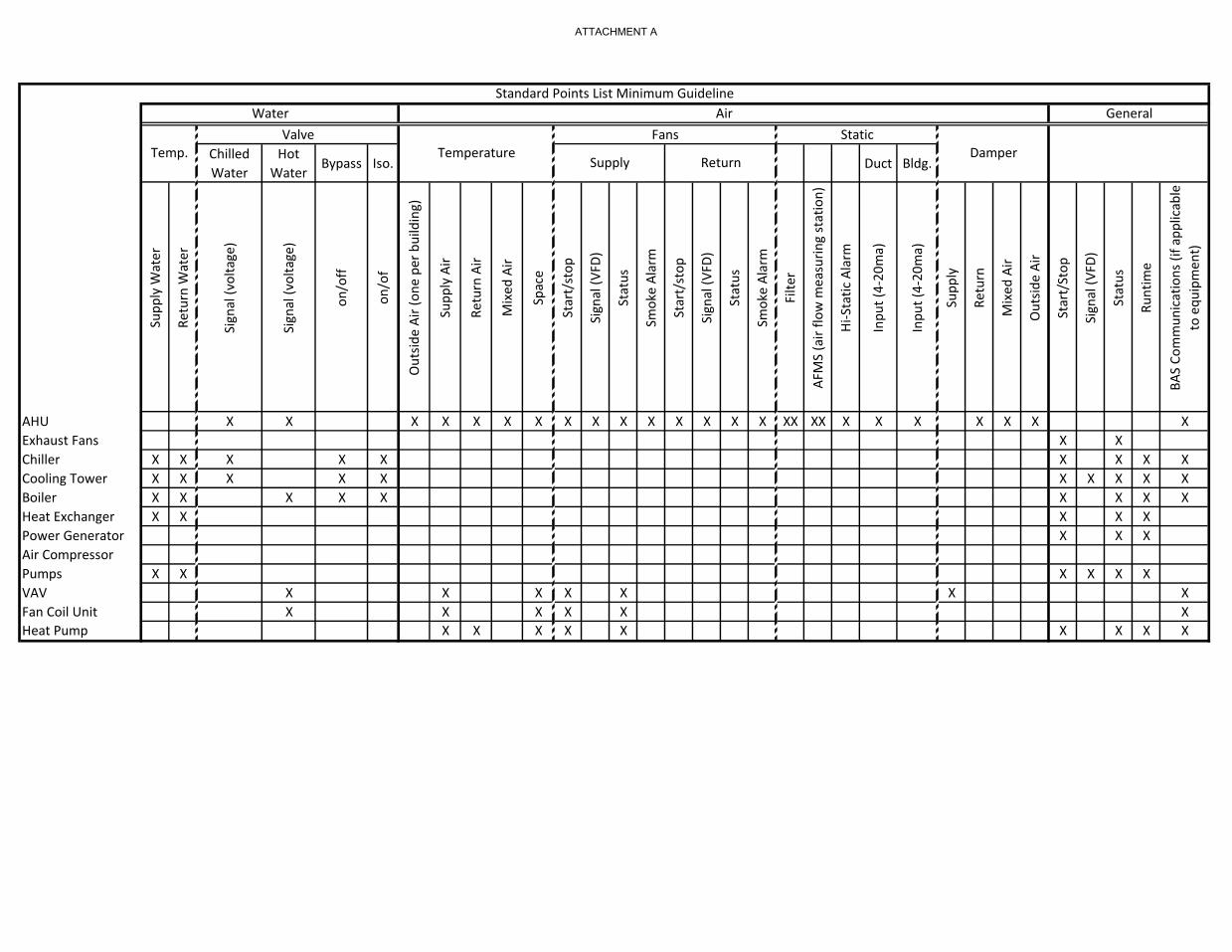
Chilled Water
Hot Water
Bypass Iso. Duct Bldg.Su
pply
Wat
er
Retu
rn W
ater
Sign
al (v
olta
ge)
Sign
al (v
olta
ge)
on/o
ff
on/o
f
Out
side
Air (
one
per b
uild
ing)
Supp
ly A
ir
Retu
rn A
ir
Mix
ed A
ir
Spac
e
Star
t/st
op
Sign
al (V
FD)
Stat
us
Smok
e Al
arm
Star
t/st
op
Sign
al (V
FD)
Stat
us
Smok
e Al
arm
Filte
r
AFM
S (a
ir flo
w m
easu
ring
stat
ion)
Hi-S
tatic
Ala
rm
Inpu
t (4-
20m
a)
Inpu
t (4-
20m
a)
Supp
ly
Retu
rn
Mix
ed A
ir
Out
side
Air
Star
t/St
op
Sign
al (V
FD)
Stat
us
Runt
ime
BAS
Com
mun
icat
ions
(if a
pplic
able
to
equ
ipm
ent)
AHU X X X X X X X X X X X X X X X XX XX X X X X X X XExhaust Fans X XChiller X X X X X X X X XCooling Tower X X X X X X X X X XBoiler X X X X X X X X XHeat Exchanger X X X X XPower Generator X X XAir CompressorPumps X X X X X XVAV X X X X X X XFan Coil Unit X X X X X XHeat Pump X X X X X X X X X
ValveWater
Standard Points List Minimum GuidelineGeneral
Temp. DamperTemperature
Air
Supply Return
Fans Static
ATTACHMENT A
Minimum Graphics Design for the AOC
Building Automation
System
All graphics will be created and animated to represent the following examples enclosed. This document is a minimum requirement for all systems in any project, which will be displayed graphically and presented to the owner for their review and approval. Inclusion in this document does not require inclusion on every project. All physical equipment will be represented on or in a graphic.
ATTACHMENT A

Table of Contents Description Page # Introduction I Logging into the System 1 Home Page Screen Overview 2 Master Schedule 3 Thermal Graphic Floor Plans 4-6 Variable Air Volume Box Graphics 6-7 AHU’s Graphics 8-10 Chiller Room Graphics 10-11 Cooling Tower Graphics 11-12 Secondary Pump Graphics 12-13 Boiler Room Graphics 13-14 Roof Exhaust Fan Graphics 14-15 Smoke Fire Panel Graphics 15-16
ATTACHMENT A
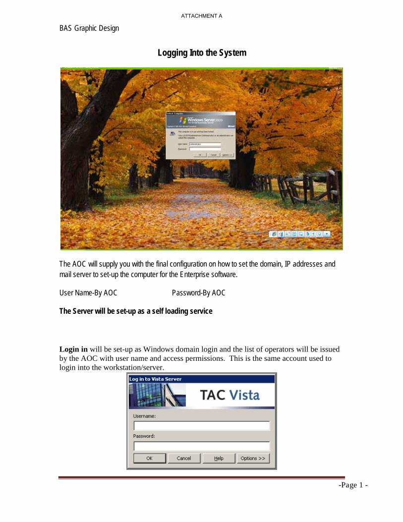
BAS Graphic Design
-Page 1 -
Logging Into the System
The AOC will supply you with the final configuration on how to set the domain, IP addresses and mail server to set-up the computer for the Enterprise software.
User Name-By AOC Password-By AOC
The Server will be set-up as a self loading service
Login in will be set-up as Windows domain login and the list of operators will be issued by the AOC with user name and access permissions. This is the same account used to login into the workstation/server.
ATTACHMENT A
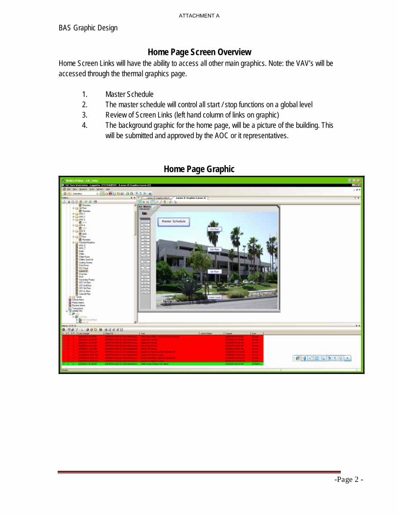
BAS Graphic Design
-Page 2 -
Home Page Screen Overview Home Screen Links will have the ability to access all other main graphics. Note: the VAV’s will be accessed through the thermal graphics page.
1. Master Schedule 2. The master schedule will control all start / stop functions on a global level 3. Review of Screen Links (left hand column of links on graphic) 4. The background graphic for the home page, will be a picture of the building. This
will be submitted and approved by the AOC or it representatives.
Home Page Graphic
ATTACHMENT A
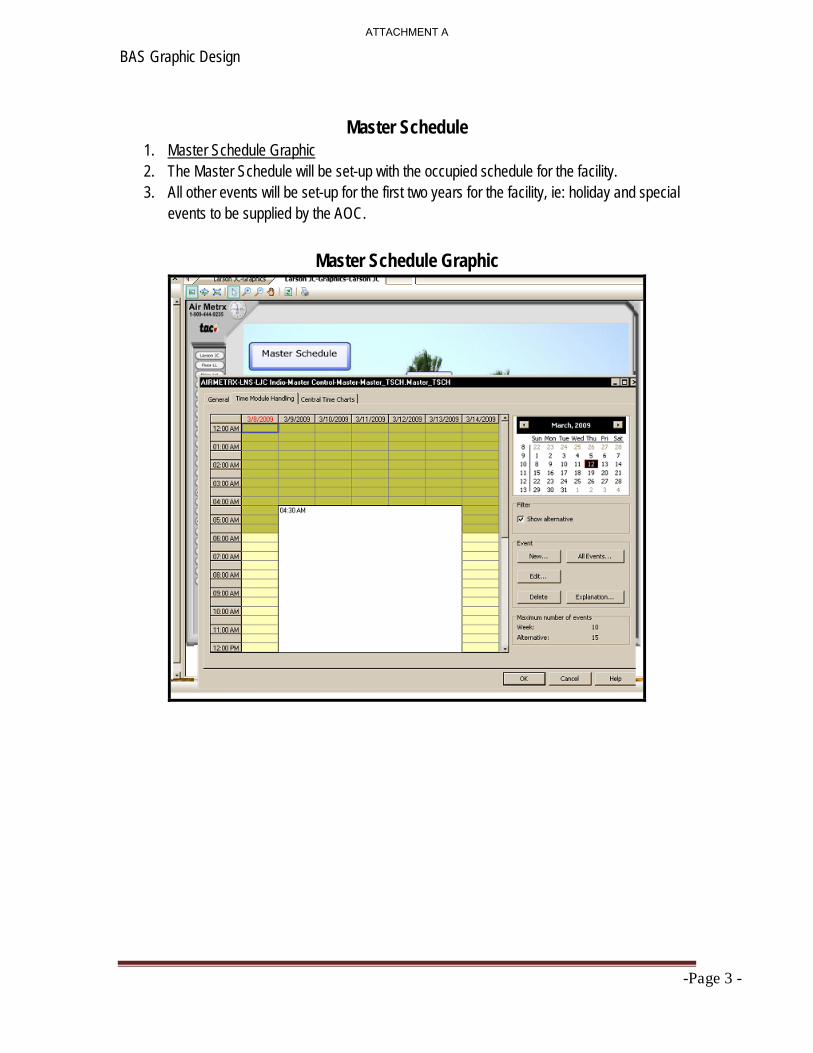
BAS Graphic Design
-Page 3 -
Master Schedule
1. Master Schedule Graphic 2. The Master Schedule will be set-up with the occupied schedule for the facility. 3. All other events will be set-up for the first two years for the facility, ie: holiday and special
events to be supplied by the AOC.
Master Schedule Graphic
ATTACHMENT A

BAS Graphic Design
-Page 4 -
Thermal Graphic Floor Plans All floors will be represented in a graphic form, (no less than one graphic per floor), which will be displayed with the minimum layers as described below.
1. The master set point for each VAV box, which will be a forcible set point. (See Figure 3)
2. A thermostat that displays the space temperature that will magnify when the curser goes over it. (See Figure 2) and (See Figure 3), for layer.
3. Hyper Link to each VAV box. (See Figure 3) 4. An (f ) next to the space temperature will display the zone has been forced. (See
Figure 3) 5. Zone # per engineering plan. (See Figure 3) 6. A color changing layer that represents the shape of the zone being supplied by the
zone. It will change color based on deviation in space temperature. Note: If the space temperature is overrode or modified, the layer will track the change. (See Figure 1) Graphic Temperature Colors in figure 1. All scaling and color will be matched unless authorized by the AOC. (See Figure 3)
7. Hyper link to all VAV’s and all other major parts of the system on this page.
Thermal Graphic Floor Plans
ATTACHMENT A

BAS Graphic Design
-Page 5 -
Graphic Temperature Colors
Figure 1
Reading Area Temperatures on the Floor Graphics
Figure 2
Layer Properties
ATTACHMENT A

BAS Graphic Design
-Page 6 -
Figure 3
Variable Air Volume Box Review
Each type of VAV box will have its own graphical representation. (One graphic for each zone) The minimum graphical representation as seen in figures 4-6 below.
1. The damper and heating coil will be dynamic. The damper will open and close based on damper position and the hot water coil will go from blue to red using 6 distinct colors based on valve position.
2. Damper position display will magnify when the curser goes over it. (See Figure 6) 3. The following will be global set points to each VAV controller from the master
controller. Application Mode ( HVAC_Cool when heating is not available and auto all other times). Occupancy Zone space temperature set point and emergency command unless otherwise called out by the AOC or it representatives.
4. The VAV DAT will be tied into the OAT and have no effect on the control of the zone.
5. If a CO2 sensor is present the zone will reset based on CO2 level, 650 ppm and below normal operations. From 650 to 1100 the box will open to 100% of damper position unless otherwised called out by the AOC or it representatives.
6. The links are as follows: home screen, floor plan, AHU and Central Plant, if applies.
7. All zones for afterhours override will bring on the associated AHU and Central Plant if needed. The zone will be set-up for two hours intervals.
Variable Air Volume Box Graphics
ATTACHMENT A

BAS Graphic Design
-Page 7 -
Figure 4
VAV Box with Re-Heat Coil
Figure 5
VAV Box with CO2 Monitor
Figure 6
ATTACHMENT A

BAS Graphic Design
-Page 8 -
Air Handling Unit Graphics The AHU’s graphics will represent the actual layout of the unit it is controlling. The look and feel will be matched based on figures 7 through 10.
1. All dampers, fans, filters, cooling coils, reset buttons, alarming, forced by operator and heating coils will be dynamic.
· The damper and indicator will open and close based on damper position. · The hot water coil will go from gray to red for hot water using 6 distinct
colors based on valve position. · The chilled water coil will go from gray to blue for chilled water using 6
distinct colors based on valve position. · The filter will flash when it is dirty. · All equipment in alarm will flash (alarm) with a white background over the
piece of equipment in alarm. · An (f ) next to the device and will display that the device has been forced. · The reset button will go from red to green when pressed and back to red
after reset is released.(Auto) 2. All process variables will be displayed with the set points. 3. Emergency shutdown will be on each page for the unit represented. 4. A time schedule for that unit that will operate the AHU, the associated zones and
the central plant. 5. Average thermal load will be displayed form the zone and will reset the discharge
temperature based on load.
AHU’s Graphics
ATTACHMENT A

BAS Graphic Design
-Page 9 -
Figure 7
Figure 8
Room/Area Air Handling Units
ATTACHMENT A

BAS Graphic Design
-Page 10 -
Figure 9
Figure 10
Chiller Room Graphics The chiller room graphics will represent the actual layout of the central plant as it is controlling. The look and feel will be matched based on figure 11.
1. All chiller, pumps, valves, reset buttons, alarming, water flow arrows and forced by
operator will be dynamic. · The chiller will display a change of state by showing the vanes moving. · The valves will go from 0-100% based on valve position. · All equipment in alarm will flash (alarm) with a white background over the
piece of equipment in alarm. · An (f ) next to the device and will display that the device has been forced. · The reset button will go from red to green when pressed and back to red
after reset is released. (Auto) · Water flow arrows will move in the direction of the water when the
equipment is occupied. 2. All process variables will be displayed with the set points. 3. Emergency shutdown will be on each page for the unit represented.
Chiller Room Graphics
ATTACHMENT A

BAS Graphic Design
-Page 11 -
Figure 11
Cooling Tower Graphics
The cooling tower graphics will represent the actual layout of the central plant as it is controlling. The look and feel will be matched based on figure 12.
4. All cooling towers, pumps, valves, reset buttons, alarming, water flow arrows and forced by
operator will be dynamic. · The cooling tower will display water flowing and fan moving in the change
of state (on) for that piece of equipment. · The valves will go from 0-100% based on valve position. · All equipment in alarm will flash (alarm) with a white background over the
piece of equipment in alarm. · An (f ) next to the device and will display that the device has been forced. · The reset button will go from red to green when pressed and back to red
after reset is released. (Auto) · Water flow arrows will move in the direction of the water when the
equipment is occupied. 5. All process variables will be displayed with the set points. 6. Emergency shutdown will be on each page for the unit represented.
ATTACHMENT A
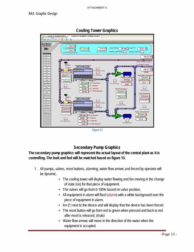
BAS Graphic Design
-Page 12 -
Cooling Tower Graphics
Figure 12
Secondary Pump Graphics The secondary pump graphics will represent the actual layout of the central plant as it is controlling. The look and feel will be matched based on figure 13.
1. All pumps, valves, reset buttons, alarming, water flow arrows and forced by operator will
be dynamic. · The cooling tower will display water flowing and fan moving in the change
of state (on) for that piece of equipment. · The valves will go from 0-100% based on valve position. · All equipment in alarm will flash (alarm) with a white background over the
piece of equipment in alarm. · An (f ) next to the device and will display that the device has been forced. · The reset button will go from red to green when pressed and back to red
after reset is released. (Auto) · Water flow arrows will move in the direction of the water when the
equipment is occupied.
ATTACHMENT A

BAS Graphic Design
-Page 13 -
2. All process variables will be displayed with the set points. 3. Emergency shutdown will be on each page for the unit represented. 4. The reset schedule will be displayed on the graphic if used.
Secondary Pump Graphics
Figure 13
Boiler Room Graphics The boiler room graphics will represent the actual layout of the central plant as it is controlling. The look and feel will be matched based on figure 14.
1. All boiler, pumps, valves, reset buttons, alarming, water flow arrows and forced by operator
will be dynamic.
· The boiler will display the flames moving and the fan moving in the change of state (on) for that piece of equipment.
· The valves will go from 0-100% based on valve position. · All equipment in alarm will flash (alarm) with a white background over the
piece of equipment in alarm. · An ( f ) next to the device and will display that the device has been forced. · The reset button will go from red to green when pressed and back to red
after reset is released. (Auto)
ATTACHMENT A

BAS Graphic Design
-Page 14 -
· Water flow arrows will move in the direction of the water when the equipment is occupied.
2. All process variables will be displayed with the set points. 3. Emergency shutdown will be on each page for the unit represented. 4. The reset schedule will be displayed on the graphic if used.
Boiler Room Graphics
Figure 14
Roof Exhaust Fan Graphics The exhaust fans graphics will represent the actual layout of the central plant as it is controlling. The look and feel will be matched based on figure 15.
1. All exhaust fans, reset buttons, alarming and forced by operator will be dynamic.
· The exhaust fans will display the color red for stop and green for run. · All equipment in alarm will flash (alarm) with a white background over the
piece of equipment in alarm. · An (f ) next to the device and will display that the device has been forced. · The reset button will go from red to green when pressed and back to red
after reset is released. (Auto)
ATTACHMENT A

BAS Graphic Design
-Page 15 -
Roof Exhaust Fan Graphics
Figure 15
Smoke Fire Panel Graphics The smoke fire panel graphics will represent the actual layout of the panel on multiple graphics. The look and feel will be matched based on figure 16-20.
1. All dampers, alarming, forced by operator will be dynamic.
· All indication will be off if the panel is disabled. When enabled the
indicators will display whether the dampers are in the open or closed position.
· All equipment in alarm will flash (alarm) with a white background over the piece of equipment in alarm.
· An ( f ) next to the device and will display that the device has been forced.
Smoke Fire Panel Graphics
ATTACHMENT A

BAS Graphic Design
-Page 16 -
Figure 16 Figure 17
Figure 18 Figure 19 Figure 20
The graphics listed above are a general guideline and are the minimum design standards. All graphics need to be submitted and approved by the AOC before installing on the host as a final product.
ATTACHMENT A