projector pa622u/pa522u pa672w/pa572w pa722x/pa622x · eu-wide legislation as implemented in each...
TRANSCRIPT

Projector
PA622U/PA522U PA672W/PA572W PA722X/PA622XUser’s Manual
Model No.NP-PA622U/NP-PA522U/NP-PA672W/NP-PA572W/NP-PA722X/NP-PA622X

Ver. 1 1/2014
• Apple,Mac,MacOS,andMacBookaretrademarksofAppleInc.registeredintheU.S.andothercountries.
• Microsoft,Windows,WindowsVista, InternetExplorer, .NETFrameworkandPowerPointareeitheraregisteredtrademarkortrademarkofMicrosoftCorporationintheUnitedStatesand/orothercountries.
• MicroSaverisaregisteredtrademarkofKensingtonComputerProductsGroup,adivisionofACCOBrands.
• Adobe,AdobePDF,AdobeReader,andAcrobatareeitherregisteredtrademarksortrademarksofAdobeSystemsIncorporatedintheUnitedStatesand/orothercountries.
• VirtualRemoteToolusesWinI2C/DDClibrary,©NicomsoftLtd.
• HDMI,theHDMILogoandHigh-DefinitionMultimediaInterfacearetrademarksorregisteredtrademarksofHDMILicensingLLC.
• DisplayPortandDisplayPortComplianceLogoaretrademarksownedbytheVideoElectronicsStandardsAssocia-tion.
• TrademarkPJLinkisatrademarkappliedfortrademarkrightsinJapan,theUnitedStatesofAmericaandothercountriesandareas.
• Wi-Fi®,Wi-FiAlliance®,andWi-FiProtectedAccess(WPA,WPA2)®are registered trademarksof theWi-FiAlli-ance.
• Blu-rayisatrademarkofBlu-rayDiscAssociation
• CRESTRONandROOMVIEWareregisteredtrademarksofCrestronElectronics,Inc.intheUnitedStatesandothercountries.
• Otherproductandcompanynamesmentionedinthisuser’smanualmaybethetrademarksorregisteredtrademarksoftheirrespectiveholders.
NOTES(1)Thecontentsofthisuser’smanualmaynotbereprintedinpartorwholewithoutpermission.
(2)Thecontentsofthisuser’smanualaresubjecttochangewithoutnotice.
(3)Greatcarehasbeentakeninthepreparationofthisuser’smanual;however,shouldyounoticeanyquestionablepoints,errorsoromissions,pleasecontactus.
(4)Notwithstandingarticle(3),NECwillnotberesponsibleforanyclaimsonlossofprofitorothermattersdeemedtoresultfromusingtheProjector.

i
Important InformationSafety CautionsPrecautionsPleasereadthismanualcarefullybeforeusingyourNECprojectorandkeepthemanualhandyforfuturereference.
CAUTIONToturnoffmainpower,besuretoremovetheplugfrompoweroutlet.Thepoweroutletsocketshouldbeinstalledasneartotheequipmentaspossible,andshouldbeeasilyaccessible.
CAUTIONTOPREVENTSHOCK,DONOTOPENTHECABINET.THEREAREHIGH-VOLTAGECOMPONENTSINSIDE.REFERSERVICINGTOQUALIFIEDSERVICEPERSONNEL.
Thissymbolwarnstheuserthatuninsulatedvoltagewithintheunitmaybesufficienttocauseelectricalshock.Therefore,itisdangeroustomakeanykindofcontactwithanypartinsideoftheunit.
Thissymbolalertstheuserthatimportantinformationconcerningtheoperationandmaintenanceofthisunithasbeenprovided.Theinformationshouldbereadcarefullytoavoidproblems.
WARNING:TOPREVENTFIREORSHOCK,DONOTEXPOSETHISUNITTORAINORMOISTURE.DONOTUSETHISUNIT’SPLUGWITHANEXTENSIONCORDORINANOUTLETUNLESSALLTHEPRONGSCANBEFULLYINSERTED.
DOC Compliance Notice (for Canada only)ThisClassBdigitalapparatuscomplieswithCanadianICES-003.
Machine Noise Information Regulation - 3. GPSGV,Thehighestsoundpressurelevelislessthan70dB(A)inaccordancewithENISO7779.
CAUTIONAvoiddisplayingstationaryimagesforaprolongedperiodoftime.DoingsocanresultintheseimagesbeingtemporarilysustainedonthesurfaceoftheLCDpanel.Ifthisshouldhappen,continuetouseyourprojector.Thestaticbackgroundfrompreviousimageswilldisappear.
Disposing of your used product
EU-widelegislationasimplementedineachMemberStaterequiresthatusedelectricalandelectronicprod-uctscarryingthemark(left)mustbedisposedofseparatelyfromnormalhouseholdwaste.Thisincludesprojectorsandtheirelectricalaccessoriesorlamps.Whenyoudisposeofsuchproducts,pleasefollowtheguidanceofyourlocalauthorityand/orasktheshopwhereyoupurchasedtheproduct.Aftercollectingtheusedproducts,theyarereusedandrecycledinaproperway.Thiseffortwillhelpusreducethewastesaswellasthenegativeimpactsuchasmercurycontainedinalamptothehumanhealthandtheenvironmentattheminimumlevel.ThemarkontheelectricalandelectronicproductsonlyappliestothecurrentEuropeanUnionMemberStates.

ii
Important Information
WARNING TO CALIFORNIA RESIDENTS:Handlingthecablessuppliedwiththisproductwillexposeyoutolead,achemicalknowntotheStateofCaliforniatocausebirthdefectsorotherreproductiveharm.WASHHANDSAFTERHANDLING.
RF Interference (for USA only)
WARNINGTheFederalCommunicationsCommissiondoesnotallowanymodificationsorchangestotheunitEXCEPTthosespecifiedbyNECDisplaySolutionsofAmerica,Inc.inthismanual.Failuretocomplywiththisgovernmentregu-lationcouldvoidyourrighttooperatethisequipment.ThisequipmenthasbeentestedandfoundtocomplywiththelimitsforaClassBdigitaldevice,pursuanttoPart15oftheFCCRules.Theselimitsaredesignedtoprovidereasonableprotectionagainstharmfulinterferenceinaresidentialinstallation.Thisequipmentgenerates,uses,andcanradiateradiofrequencyenergyand,ifnotinstalledandusedinaccordancewiththeinstructions,maycauseharmfulinterferencetoradiocommunications.However,thereisnoguaranteethatinterferencewillnotoccurinaparticularinstallation.Ifthisequipmentdoescauseharmfulinterferencetoradioortelevisionreception,whichcanbedeterminedbyturningtheequipmentoffandon,theuserisencouragedtotrytocorrecttheinterferencebyoneormoreofthefollowingmeasures:
• Reorientorrelocatethereceivingantenna.• Increasetheseparationbetweentheequipmentandreceiver.• Connecttheequipmentintoanoutletonacircuitdifferentfromthattowhichthereceiverisconnected.• Consultthedealeroranexperiencedradio/TVtechnicianforhelp.
ForUKonly:InUK,aBSapprovedpowercordwithmouldedplughasaBlack(fiveAmps)fuseinstalledforusewiththisequipment.Ifapowercordisnotsuppliedwiththisequipmentpleasecontactyoursupplier.
Important SafeguardsThesesafetyinstructionsaretoensurethelonglifeofyourprojectorandtopreventfireandshock.Pleasereadthemcarefullyandheedallwarnings.
Installation• Donotplacetheprojectorinthefollowingconditions:- onanunstablecart,stand,ortable.- nearwater,baths,ordamprooms.- indirectsunlight,nearheaters,orheatradiatingappliances.- inadusty,smokyorsteamyenvironment.- onasheetofpaperorcloth,rugsorcarpets.• Ifyouwishtohavetheprojectorinstalledontheceiling:- Donotattempttoinstalltheprojectoryourself.- Theprojectormustbeinstalledbyqualifiedtechniciansinordertoensureproperoperationandreducetheriskofbodilyinjury.- Inaddition,theceilingmustbestrongenoughtosupporttheprojectorandtheinstallationmustbeinaccordancewithanylocalbuildingcodes.- Pleaseconsultyourdealerformoreinformation.

iii
Important Information
WARNING• Donotcoverthelenswiththelenscaporequivalentwhiletheprojectorison.Doingsocanleadtomeltingofthecapduetotheheatemittedfromthelightoutput.
• Donotplaceanyobjects,whichareeasilyaffectedbyheat,infrontoftheprojectorlens.Doingsocouldleadtotheobjectmeltingfromtheheatthatisemittedfromthelightoutput.
Donotusetheprojectorwithitleaningtotheleftandright.Thismayresultinamalfunction.However,portraitinstal-lationispossible*(whenacustom-designedstandismade).Forportraitinstallation,installtheprojectorwiththeairintakeatthebottomandleaveaspaceofatleast130mmbelowtheairintake.
130 mm or more
Fire and Shock Precautions • Ensurethatthereissufficientventilationandthatventsareunobstructedtopreventthebuild-upofheatinsideyourprojector.Allowenoughspacebetweenyourprojectorandawall.(→pagevii)• Donottrytotouchtheventilationoutletontheleftfront(whenseenfromthefront)asitcanbecomeheatedwhiletheprojectoristurnedonandimmediatelyaftertheprojectoristurnedoff.Partsoftheprojectormaybecometem-porarilyheatediftheprojectoristurnedoffwiththePOWERbuttonoriftheACpowersupplyisdisconnectedduringnormalprojectoroperation. Usecautionwhenpickinguptheprojector.
• Preventforeignobjectssuchaspaperclipsandbitsofpaperfromfallingintoyourprojector.Donotattempttoretrieveanyobjectsthatmightfallintoyourprojector.Donotinsertanymetalobjectssuchasawireorscrewdriverintoyourprojector.Ifsomethingshouldfallintoyourprojector,disconnectitimmediatelyandhavetheobjectremovedbyaqualifiedservicepersonnel.• Donotplaceanyobjectsontopoftheprojector.• Donottouchthepowerplugduringathunderstorm.Doingsocancauseelectricalshockorfire.• Theprojectorisdesignedtooperateonapowersupplyof100-240VAC50/60Hz.Ensurethatyourpowersupplyfitsthisrequirementbeforeattemptingtouseyourprojector.• Donotlookintothelenswhiletheprojectorison.Seriousdamagetoyoureyescouldresult.
• Keepanyitems(magnifyingglassetc.)outofthelightpathoftheprojector.Thelightpathbeingprojectedfromthelensisextensive,thereforeanykindofabnormalobjectsthatcanredirectlightcomingoutofthelens,cancauseanunpredictableoutcomesuchasafireorinjurytotheeyes.• Donotplaceanyobjects,whichareeasilyaffectedbyheat,infrontofaprojectorexhaustvent. Doingsocouldleadtotheobjectmeltingorgettingyourhandsburnedfromtheheatthatisemittedfromtheex-haust.

iv
Important Information
• Handlethepowercordcarefully.Adamagedorfrayedpowercordcancauseelectricshockorfire.- Donotuseanypowercordotherthantheonesuppliedwiththeprojector.- Donotbendortugthepowercordexcessively.- Donotplacethepowercordundertheprojector,oranyheavyobject.- Donotcoverthepowercordwithothersoftmaterialssuchasrugs.- Donotheatthepowercord.- Donothandlethepowerplugwithwethands.• Turnofftheprojector,unplugthepowercordandhavetheprojectorservicedbyaqualifiedservicepersonnelunderthefollowingconditions:- Whenthepowercordorplugisdamagedorfrayed.- Ifliquidhasbeenspilledintotheprojector,orifithasbeenexposedtorainorwater.- Iftheprojectordoesnotoperatenormallywhenyoufollowtheinstructionsdescribedinthisuser’smanual.- Iftheprojectorhasbeendroppedorthecabinethasbeendamaged.- Iftheprojectorexhibitsadistinctchangeinperformance,indicatinganeedforservice.• Disconnectthepowercordandanyothercablesbeforecarryingtheprojector.• Turnofftheprojectorandunplugthepowercordbeforecleaningthecabinetorreplacingthelamp.• Turnofftheprojectorandunplugthepowercordiftheprojectorisnottobeusedforanextendedperiodoftime.• WhenusingaLANcable: Forsafety,donotconnecttotheconnectorforperipheraldevicewiringthatmighthaveexcessivevoltage.
CAUTION• Donotusethetilt-footforpurposesotherthanoriginallyintended.Misusessuchasgrippingthetilt-footorhang-ingonthewallcancausedamagetotheprojector.• Donotsendtheprojectorinthesoftcasebyparceldeliveryserviceorcargoshipment.Theprojectorinsidethesoftcasecouldbedamaged.• Select[HIGH]inFanmodeifyoucontinuetousetheprojectorforconsecutivedays.(Fromthemenu,select[SETUP]→[OPTIONS(1)]→[FANMODE]→[MODE]→[HIGH].)• Donotmovetheprojectorbyholdingthecablecover.Doingsomayresult intheprojectorfallingorcausinginjury.• Donotunplugthepowercablefromthewalloutletorprojectorwhentheprojectorispoweredon.DoingsocancausedamagetotheACINconnectoroftheprojectorand(or)theprongplugofthepowercable. ToturnofftheACpowersupplywhentheprojectorispoweredon,useapowerstripequippedwithaswitchandabreaker.• DonotturnofftheACpowerfor60secondsafterthelampisturnedonandwhilethePOWERindicatorisblink-ingblue.Doingsocouldcauseprematurelampfailure.
Caution on Handling the Optional LensWhenshippingtheprojectorwiththelens,removethelensbeforeshippingtheprojector.Alwaysattachthedustcaptothelenswheneveritisnotmountedontheprojector.Thelensandthelensshiftmechanismmayencounterdamagecausedbyimproperhandlingduringtransportation.Donotholdthelenspartwhencarryingtheprojector.Doingsocouldcausethefocusringtorotate,resultinginaccidentaldroppingoftheprojector.
Remote Control Precautions• Handletheremotecontrolcarefully.• Iftheremotecontrolgetswet,wipeitdryimmediately.• Avoidexcessiveheatandhumidity.• Donotshort,heat,ortakeapartbatteries.• Donotthrowbatteriesintofire.• Ifyouwillnotbeusingtheremotecontrolforalongtime,removethebatteries.• Ensurethatyouhavethebatteries’polarity(+/−)alignedcorrectly.• Donotusenewandoldbatteriestogether,orusedifferenttypesofbatteriestogether.• Disposeofusedbatteriesaccordingtoyourlocalregulations.

v
Important Information
Note for US ResidentsThelampinthisproductcontainsmercury.PleasedisposeaccordingtoLocal,StateorFederalLaws.
Lamp Replacement• Usethespecifiedlampforsafetyandperformance.• Toreplacethelamp,followallinstructionsprovidedonpage142.• Besuretoreplacethelampandfilterwhenthemessage[THE LAMP HAS REACHED THE END OF ITS USABLE
LIFE. PLEASE REPLACE THE LAMP AND FILTER. USE THE SPECIFIED LAMP FOR SAFETY AND PERFOR-MANCE.]appears.Ifyoucontinuetousethelampafterthelamphasreachedtheendofitsusablelife,thelampbulbmayshatter,andpiecesofglassmaybescatteredinthelampcase.Donottouchthemasthepiecesofglassmaycauseinjury. Ifthishappens,contactyourdealerforlampreplacement.
A Lamp CharacteristicTheprojectorhasahigh-pressuremercurylampasalightsource.Alamphasacharacteristicthatitsbrightnessgraduallydecreaseswithage.Alsorepeatedlyturningthelamponandoffwillincreasethepossibilityofitslowerbrightness.
CAUTION:• DONOTTOUCHTHELAMPimmediatelyafterithasbeenused.Itwillbeextremelyhot.Turntheprojectoroffandthendisconnectthepowercord.Allowatleastonehourforthelamptocoolbeforehandling.• Whenremovingthelampfromaceiling-mountedprojector,makesurethatnooneisundertheprojector.Glassfragmentscouldfallifthelamphasbeenburnedout.
About High Altitude mode• Set[FANMODE]to[HIGHALTITUDE]whenusingtheprojectorataltitudesapproximately5249feet/1600metersorhigher. Usingtheprojectorataltitudesapproximately5249feet/1600metersorhigherwithoutsettingto[HIGHALTITUDE]cancausetheprojectortooverheatandtheprotectorcouldshutdown.Ifthishappens,waitacoupleminutesandturnontheprojector.• Usingtheprojectorataltitudeslessthanapproximately5249feet/1600metersandsettingto[HIGHALTITUDE]cancausethelamptoovercool,causingtheimagetoflicker.Switch[FANMODE]to[AUTO].• Usingtheprojectorataltitudesapproximately5249feet/1600metersorhighercanshortenthelifeofopticalcom-ponentssuchasthelamp.
About Copyright of original projected pictures:Pleasenotethatusingthisprojectorforthepurposeofcommercialgainortheattractionofpublicattentioninavenuesuchasacoffeeshoporhotelandemployingcompressionorexpansionofthescreenimagewiththefollowingfunc-tionsmayraiseconcernabouttheinfringementofcopyrightswhichareprotectedbycopyrightlaw.[ASPECTRATIO],[KEYSTONE],Magnifyingfeatureandothersimilarfeatures.
Turkish RoHS information relevant for Turkish marketEEE Yönetmeliğine Uygundur.
Thisdeviceisnotintendedforuseinthedirectfieldofviewatvisualdisplayworkplaces.Toavoidincommodingreflec-tionsatvisualdisplayworkplacesthisdevicemustnotbeplacedinthedirectfieldofview.

vi
Important Information
Health precautions to users viewing 3D images
Beforeviewing,besuretoreadhealthcareprecautionsthatmaybefoundintheuser’smanualincludedwithyour3Deyeglassesoryour3DcompatiblecontentsuchasBlu-rayDiscs,videogames,computer’svideofilesandthelike.Toavoidanyadversesymptoms,heedthefollowing:• Donotuse3Deyeglassesforviewinganymaterialotherthan3Dimages.• Allowadistanceof2m/7feetorgreaterbetweenthescreenandauser.Viewing3Dimagesfromtoocloseadistancecanstrainyoureyes.• Avoidviewing3Dimagesforaprolongedperiodoftime.Takeabreakof15minutesorlongeraftereveryhourofviewing.• Ifyouoranymemberofyourfamilyhasahistoryoflight-sensitiveseizures,consultadoctorbeforeviewing3Dimages.• Whileviewing3Dimages,ifyougetsicksuchasnausea,dizziness,queasiness,headache,eyestrain,blurryvision,convulsions,andnumbness,stopviewingthem.Ifsymptomsstillpersist,consultadoctor.• View3Dimagesfromthefrontofthescreen.Viewingfromananglemaycausefatigueoreyestrain.
Power management functionInordertokeeppowerconsumptionlow,thefollowingpowermanagementfunctions(1)and(2)havebeensetwhenshippedfromthefactory.Pleasedisplaytheon-screenmenuandchangethesettings(1)and(2)accordingtotheaimofusingtheprojector.
1. STANDBY MODE (Factory preset: NORMAL)
• When[NORMAL]isselectedfor[STANDBYMODE],thefollowingconnectorsandfunctionswillnotwork:
HDMIOUTconnector,AUDIOOUTconnector,Ethernet/HDBaseTPort,USB-APort,LANfunctions,MailAlertfunction
(→page114)
2. AUTO POWER OFF (Factory preset: 60 minutes)
• When[1:00]isselectedfor[AUTOPOWEROFF],youcanenabletheprojectortoautomaticallyturnoffin1hourifthereisnosignalreceivedbyanyinputorifnooperationisperformed.
(→page115)

vii
Important Information
Clearance for Installing the ProjectorAllowampleclearancebetweentheprojectoranditssurroundingsasshownbelow.Thehightemperatureexhaustcomingoutofthedevicemaybesuckedintothedeviceagain.AvoidinstallingtheprojectorinaplacewhereairmovementfromtheHVACisdirectedattheprojector.HeatedairfromtheHVACcanbetakeninbytheprojector'sintakevent.Ifthishappens,thetemperatureinsidetheprojectorwillrisetoohighcausingtheover-temperatureprotectortoautomaticallyturnofftheprojectorspower.
Example 1 – If there are walls on both sides of the projector.
20cm/7.9"orgreater 13cm/5.1"orgreater
Filtercover(Ventilation(inlet))
Lampcover
NOTE:The drawing shows the proper clearance required for the front, back and top of the projector.
Example 2 – If there is a wall behind the projector.
10cm/3.9"orgreater
Ventilation(outlet)
NOTE:The drawing shows the proper clearance required for the back, sides and top of the projector.
Example 3 – In the case of portrait projection.
Filtercover(Ventilation(inlet))
13cm/5.1"orgreater
NOTE:• Thedrawingshowstheproperclearancerequiredforthefront,backandtopoftheprojector.• Seepage134 for an installation example on portrait projection.
viii
Table of ContentsImportant Information ............................................................................................ i
1. Introduction ...........................................................................................................1❶What’sintheBox? ..........................................................................................................1❷IntroductiontotheProjector ...........................................................................................2
CongratulationsonYourPurchaseoftheProjector ..................................................2Installation .................................................................................................................2Videos .......................................................................................................................2Network .....................................................................................................................3Energy-saving ...........................................................................................................3Maintenance .............................................................................................................3Aboutthisuser’smanual ...........................................................................................4
❸PartNamesoftheProjector ...........................................................................................5Front/Top ...................................................................................................................5Rear ..........................................................................................................................6ControlPanel/IndicatorSection ................................................................................7TerminalPanelFeatures ...........................................................................................8
❹PartNamesoftheRemoteControl ................................................................................9BatteryInstallation ..................................................................................................10RemoteControlPrecautions ...................................................................................10OperatingRangeforWirelessRemoteControl .......................................................11
2. Projecting an Image (Basic Operation) ...............................................12❶FlowofProjectinganImage .........................................................................................12❷ConnectingYourComputer/ConnectingthePowerCord ..............................................13❸TurningontheProjector ...............................................................................................14
NoteonStartupscreen(MenuLanguageSelectscreen) .......................................15❹SelectingaSource .......................................................................................................16
Selectingthecomputerorvideosource..................................................................16❺AdjustingthePictureSizeandPosition ........................................................................18
Adjustingtheverticalpositionofaprojectedimage(Lensshift) .............................19Focus ......................................................................................................................20Applicablelens:NP30ZL .........................................................................................21Applicablelens:NP11FL .........................................................................................22Zoom .......................................................................................................................23AdjustingtheTiltFeet .............................................................................................23
❻OptimizingComputerSignalAutomatically ..................................................................24AdjustingtheImageUsingAutoAdjust ...................................................................24
❼TurningUporDownVolume .........................................................................................24❽TurningofftheProjector ...............................................................................................25❾AfterUse.......................................................................................................................26
3. Convenient Features ......................................................................................27❶TurningofftheImageandSound .................................................................................27❷FreezingaPicture ........................................................................................................28❸EnlargingaPicture .......................................................................................................28❹ChangingEcoMode/CheckingEnergy-SavingEffectUsingEcoMode[ECO
MODE] ....................................................................................................................29

ix
Table of Contents
CheckingEnergy-SavingEffect[CARBONMETER] ..............................................30❺UsingtheOptionalRemoteMouseReceiver(NP01MR) .............................................31❻CorrectingHorizontalandVerticalKeystoneDistortion[CORNERSTONE] .................33❼PreventingtheUnauthorizedUseoftheProjector[SECURITY] ..................................36❽Projecting3Dvideos.....................................................................................................39
Proceduretowatch3Dvideosusingthisprojector .................................................39Whenvideoscannotbeviewedin3D .....................................................................41
❾ControllingtheProjectorbyUsinganHTTPBrowser ..................................................42
4. Multi-Screen Projection ...............................................................................48❶Thingsthatcanbedoneusingmulti-screenprojection ................................................48
Case1.Usingasingleprojectortoprojecttwotypesofvideos[PIP/PICTUREBYPICTURE] .........................................................................................................48Case2.Usingfourprojectors(liquidcrystalpanel:XGA)toprojectvideoswitharesolutionof1920×1080pixels[TILING]............................................................49Thingstonotewheninstallingprojectors ................................................................51
❷DisplayingTwoPicturesattheSameTime ...................................................................52Projectingtwoscreens ............................................................................................53Switchingthemaindisplaywiththesub-displayandviceversa .............................54Restrictions .............................................................................................................55
❸DisplayingaPictureUsing[EDGEBLENDING] ...........................................................56Settingtheoverlapofprojectionscreens ................................................................57BlackLevelAdjustment ...........................................................................................60
5. Using On-Screen Menu .................................................................................62❶UsingtheMenus ...........................................................................................................62❷MenuElements .............................................................................................................63❸ListofMenuItems ........................................................................................................64❹MenuDescriptions&Functions[INPUT] ......................................................................70
1:HDMI1 ..................................................................................................................702:HDMI2 ..................................................................................................................703:DisplayPort ...........................................................................................................704:BNC .....................................................................................................................705:BNC(CV) ..............................................................................................................706:BNC(Y/C) .............................................................................................................707:COMPUTER ........................................................................................................708:HDBaseT .............................................................................................................70ENTRYLIST ...........................................................................................................70TESTPATTERN ......................................................................................................70
❺MenuDescriptions&Functions[ADJUST] ...................................................................74[PICTURE] ..............................................................................................................74[IMAGEOPTIONS] .................................................................................................78[VIDEO] ...................................................................................................................82[3DSETTINGS] ......................................................................................................84
❻MenuDescriptions&Functions[DISPLAY] ..................................................................85[PIP/PICTUREBYPICTURE] .................................................................................85[GEOMETRICCORRECTION] ...............................................................................87[EDGEBLENDING] ................................................................................................91[MULTISCREEN]....................................................................................................92
x
Table of Contents
❼MenuDescriptions&Functions[SETUP] .....................................................................94[MENU] ...................................................................................................................94[INSTALLATION] .....................................................................................................96[CONTROL] ............................................................................................................99[NETWORKSETTINGS] .......................................................................................107[SOURCEOPTIONS] ...........................................................................................112[POWEROPTIONS] .............................................................................................114ReturningtoFactoryDefault[RESET] ..................................................................116
❽MenuDescriptions&Functions[INFO.] .....................................................................118[USAGETIME] ......................................................................................................118[SOURCE(1)] ........................................................................................................119[SOURCE(2)] ........................................................................................................119[WIREDLAN] ........................................................................................................119[VERSION(1)] .......................................................................................................120[OTHERS] .............................................................................................................120[CONDITIONS] .....................................................................................................121[HDBaseT] ............................................................................................................122
6. Connecting to Other Equipment ...........................................................123❶Mountingalens(soldseparately) ...............................................................................123
Mountingthelens..................................................................................................123Removingthelens ................................................................................................124
❷MakingConnections ...................................................................................................125AnalogRGBsignalconnection .............................................................................125DigitalRGBsignalconnection ..............................................................................126ConnectinganExternalMonitor ...........................................................................129ConnectingYourBlu-rayPlayerorOtherAVEquipment .......................................130ConnectingComponentInput ...............................................................................131ConnectingHDMIInput.........................................................................................132ConnectingtoaHDBaseTtransmissiondevice(soldcommercially) ....................133Portraitprojection(verticalorientation) .................................................................134ConnectingtoaWiredLAN ..................................................................................137
7. Maintenance .....................................................................................................138❶CleaningtheFilters.....................................................................................................138❷CleaningtheLens.......................................................................................................141❸CleaningtheCabinet ..................................................................................................141❹ReplacingtheLampandtheFilters ............................................................................142
8. User Supportware ..........................................................................................147❶OperatingEnvironmentforSoftwareIncludedonCD-ROM .......................................147
NamesandFeaturesofBundledSoftwarePrograms ...........................................147Downloadservice .................................................................................................147OperatingEnvironment .........................................................................................147
❷InstallingSoftwareProgram .......................................................................................148InstallationforWindowssoftware ..........................................................................148
❸OperatingtheProjectorViatheLAN(VirtualRemoteTool) ........................................151ConnecttheprojectortoaLAN. ............................................................................152
❹ControllingtheProjectoroveraLAN(PCControlUtilityPro4/Pro5) ........................154

xi
Table of Contents
9. Appendix ..............................................................................................................158❶Throwdistanceandscreensize .................................................................................158
Lenstypesandthrowdistance .............................................................................158Tablesofscreensizesanddimensions ................................................................161Lensshiftingrange ................................................................................................162
❷CompatibleInputSignalList .......................................................................................164❸Specifications .............................................................................................................167❹CabinetDimensions ...................................................................................................169❺Mountingthecablecover(soldseparately) ................................................................170❻Pinassignmentsandsignalnamesofmainconnectors .............................................171❼Troubleshooting ..........................................................................................................173
IndicatorMessages ...............................................................................................173CommonProblems&Solutions ............................................................................175Ifthereisnopicture,orthepictureisnotdisplayedcorrectly. ...............................177
❽PCControlCodesandCableConnection ..................................................................178❾TroubleshootingCheckList .........................................................................................179

1
1. Introduction❶ What’s in the Box?Makesureyourboxcontainseverythinglisted.Ifanypiecesaremissing,contactyourdealer.Pleasesavetheoriginalboxandpackingmaterialsifyoueverneedtoshipyourprojector.
Projector
Dustcapforlens* Theprojectorisshippedwithout
alens.Forthetypesoflensandthrowdistances,seepage158.
Remotecontrol(7N900961)
AAalkalinebatteries(x2)
Inputselectionchar-acterseal
Powercord(US:7N080241)(EU:7N080022)
Lenstheftpreventionscrew(24V00841)Thisscrewmakesitdifficulttoremovethelensmountedontheprojector.(→page124)
Straps(24J23901)(forpreventinglampcoverfromfalling)Attachingthestrapstothelampcoverpreventsthemfromfallingwhentheprojectorissuspendedfromtheceiling.
For North America onlyRegistrationcardLimitedwarrantyFor customers in Europe: YouwillfindourcurrentvalidGuar-anteePolicyonourWebSite:www.nec-display-solutions.com
• ImportantInfomation(ForNorthAmerica:7N8N4121)(ForOthercountriesthanNorthAmerica:7N8N4121and7N8N4131)
• QuickSetupGuide(ForNorthAmerica:7N8N4141)(ForOthercountriesthanNorthAmerica:7N8N4141and7N8N4151)
NECProjectorCD-ROMUser’smanual(PDF)andtheutilitysoftware(7N951971)
2
1. Introduction
❷ Introduction to the ProjectorThissectionintroducesyoutoyournewprojectoranddescribesthefeaturesandcontrols.
Congratulations on Your Purchase of the ProjectorThisprojectorisoneoftheverybestprojectorsavailabletoday.Theprojectorenablesyoutoprojectpreciseimagesupto500inchesacross(measureddiagonally)fromyourPCorMaccomputer(desktopornotebook),VCR,Blu-rayplayer,ordocumentcamera.Youcanusetheprojectoronatabletoporcart,youcanusetheprojectortoprojectimagesfrombehindthescreen,andtheprojectorcanbepermanentlymountedonaceiling*1.Theremotecontrolcanbeusedwirelessly.
*1 Donotattempttomounttheprojectoronaceilingyourself.
Theprojectormustbeinstalledbyqualifiedtechniciansinordertoensureproperoperationandreducetheriskofbodilyinjury.
Inaddition,theceilingmustbestrongenoughtosupporttheprojectorandtheinstallationmustbeinaccordancewithanylocalbuildingcodes.Pleaseconsultyourdealerformoreinformation.
Installation
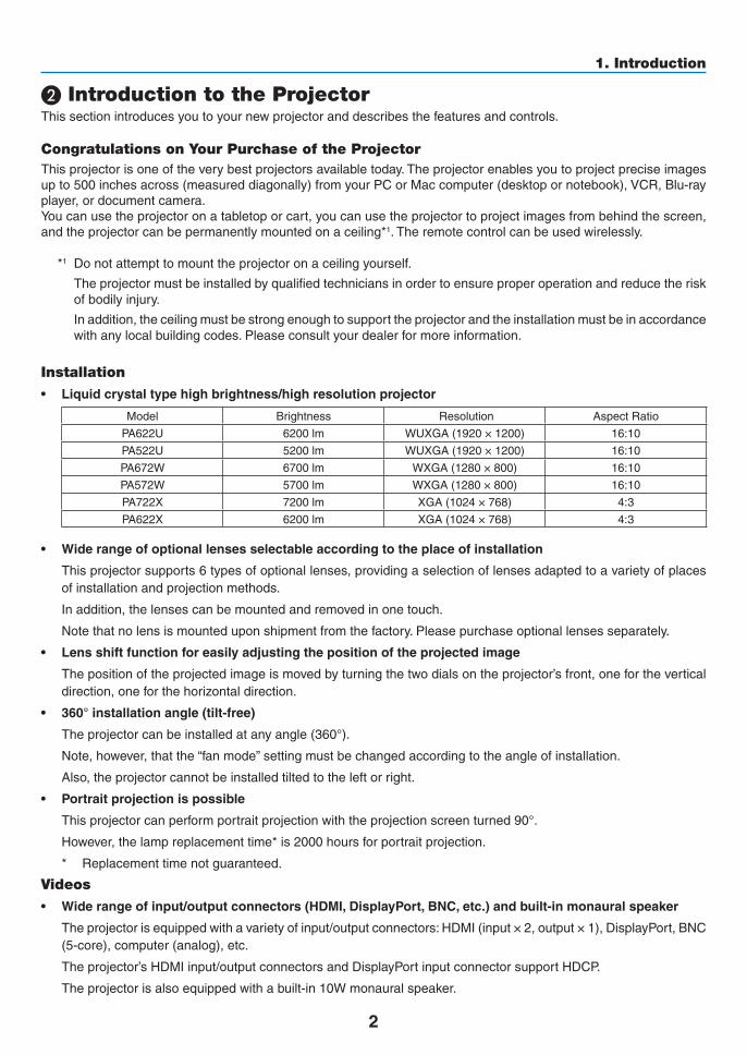
• Liquidcrystaltypehighbrightness/highresolutionprojector
Model Brightness Resolution AspectRatio
PA622U 6200lm WUXGA(1920×1200) 16:10
PA522U 5200lm WUXGA(1920×1200) 16:10
PA672W 6700lm WXGA(1280×800) 16:10
PA572W 5700lm WXGA(1280×800) 16:10
PA722X 7200lm XGA(1024×768) 4:3
PA622X 6200lm XGA(1024×768) 4:3
• Widerangeofoptionallensesselectableaccordingtotheplaceofinstallation
Thisprojectorsupports6typesofoptionallenses,providingaselectionoflensesadaptedtoavarietyofplacesofinstallationandprojectionmethods.
Inaddition,thelensescanbemountedandremovedinonetouch.
Notethatnolensismounteduponshipmentfromthefactory.Pleasepurchaseoptionallensesseparately.
• Lensshiftfunctionforeasilyadjustingthepositionoftheprojectedimage
Thepositionoftheprojectedimageismovedbyturningthetwodialsontheprojector’sfront,onefortheverticaldirection,oneforthehorizontaldirection.
• 360°installationangle(tilt-free)
Theprojectorcanbeinstalledatanyangle(360°).
Note,however,thatthe“fanmode”settingmustbechangedaccordingtotheangleofinstallation.
Also,theprojectorcannotbeinstalledtiltedtotheleftorright.
• Portraitprojectionispossible
Thisprojectorcanperformportraitprojectionwiththeprojectionscreenturned90°.
However,thelampreplacementtime*is2000hoursforportraitprojection.
* Replacementtimenotguaranteed.
Videos
• Widerangeofinput/outputconnectors(HDMI,DisplayPort,BNC,etc.)andbuilt-inmonauralspeaker
Theprojectorisequippedwithavarietyofinput/outputconnectors:HDMI(input×2,output×1),DisplayPort,BNC(5-core),computer(analog),etc.
Theprojector’sHDMIinput/outputconnectorsandDisplayPortinputconnectorsupportHDCP.
Theprojectorisalsoequippedwithabuilt-in10Wmonauralspeaker.

3
1. Introduction
• EquippedwithHDBaseTinputterminal
ThisprojectorisequippedwithaHDBaseTinputterminalwhichcanbeconnectedtoaHDBaseTtransmissiondevicesoldcommercially.
HDBaseTisaconnectionstandardforhomeappliancesthatisestablishedbytheHDBaseTAlliance.
• Simultaneousdisplayof2images(PIP/PICTUREBYPICTURE)
Twoimagescanbeprojectedsimultaneouslywithasingleprojector.
Therearetwotypesoflayoutsforthetwoimages:“picture-in-picture”inwhichasub-pictureisdisplayedonthemainpicture,and“picture-by-picture”inwhichthemainandsubpicturesaredisplayednexttoeachother.
• Multi-screenprojectionusingmultipleprojectors
ThisprojectorisequippedwithmultipleHDMIinput&outputterminalsthatcanconnectmultipleprojectorsinadigitalchain.Ahighqualitypictureisachievedbydividingandprojectinghighresolutionvideosamongthevariousprojectors.
Furthermore,theboundariesofthescreensaresmoothedusinganedgeblendingfunction.
• Seamlessswitchfunctionforsmootherscreenchangeswhenswitchingthesignal
Whentheinputconnectorisswitched,theimagedisplayedbeforeswitchingisheldsothatthatthenewimagecanbeswitchedtowithoutabreakduetoabsenceofasignal.
• SupportsHDMI3Dformat
Thisprojectorcanbeusedtowatchvideosin3Dusingcommercially-availableactiveshutter-type3Deyewearand3DemittersthatsupportXpand3D.
Network
• Convenientutilitysoftware(UserSupportware)providedasstandard
ThethreeutilitysoftwarestoredintheenclosedNECProjectorCD-ROM(VirtualRemoteTool,PCControlUtilityPro4(forWindows)andPCControlUtilityPro5(forMacOS))canbeused.ThefollowingthreeutilitysoftwareontheCD-ROMcannotbeused.
ImageExpressUtilityLite(forWindows/MacOS),ImageExpressUtility2.0(forWindows)andDesktopControlUtility1.0(forWindows)
Energy-saving
• Energy-saving design with a standby power consumption of 0.11 watts (100-130V)/0.16 watts (200-240V)
Whentheon-screenmenu’sstandbymodeissetto“NORMAL”,thepowerconsumptioninthestandbymodeis0.11watts.
• “Ecomode”forlowpowerconsumptionand“CarbonMeter”display
Theprojector is equippedwith an“ecomode” for reducingpower consumptionduringuse.Furthermore, thepower-savingeffectwhentheecomodeissetisconvertedintotheamountofreductionsofCO2emissionsandthisisindicatedontheconfirmationmessagedisplayedwhenthepoweristurnedoffandat“Information”ontheon-screenmenu(CARBONMETER).
Maintenance
• Maximumlampreplacementtimeof4000hoursandnoneedtocleanthefilters
Whenusedintheecomode,thelampreplacementtime*isextendedtoamaximumof4000hours.
*Thistimeisnotguaranteed.
Furthermore,thisprojectoruseslarge2-layerfilters.Whenthesefiltersarereplacedwithnewoneswhenchangingthelamp,thereisnoneedforregularfiltercleaning.

4
1. Introduction
About this user’s manualThefastestwaytogetstartedistotakeyourtimeanddoeverythingrightthefirsttime.Takeafewminutesnowtoreviewtheuser’smanual.Thismaysaveyoutimelateron.Atthebeginningofeachsectionofthemanualyou’llfindanoverview.Ifthesectiondoesn’tapply,youcanskipit.
5
1. Introduction
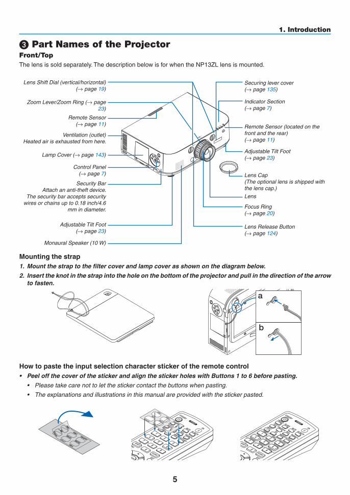
❸ Part Names of the ProjectorFront/TopThelensissoldseparately.ThedescriptionbelowisforwhentheNP13ZLlensismounted.
ControlPanel(→page7)
LensShiftDial(vertical/horizontal)(→page19)
Lens
RemoteSensor(locatedonthefrontandtherear)(→page11)
RemoteSensor(→page11)
ZoomLever/ZoomRing(→page23)
LensCap(Theoptionallensisshippedwiththelenscap.)
FocusRing(→page20)
AdjustableTiltFoot (→page23)
IndicatorSection(→page7)
Securinglevercover(→page135)
LensReleaseButton(→page124)
AdjustableTiltFoot(→page23)
Ventilation(outlet)Heatedairisexhaustedfromhere.
Mounting the strap1. Mount the strap to the filter cover and lamp cover as shown on the diagram below.
2. Insert the knot in the strap into the hole on the bottom of the projector and pull in the direction of the arrow to fasten.
a
b
Howtopastetheinputselectioncharacterstickeroftheremotecontrol• PeeloffthecoverofthestickerandalignthestickerholeswithButtons1to6beforepasting.
• Pleasetakecarenottoletthestickercontactthebuttonswhenpasting.
• Theexplanationsandillustrationsinthismanualareprovidedwiththestickerpasted.
LampCover(→page143)
SecurityBarAttachananti-theftdevice.
Thesecuritybaracceptssecuritywiresorchainsupto0.18inch/4.6
mmindiameter.
MonauralSpeaker(10W)

6
1. Introduction
TerminalPanel(→page8)
RearRemoteSensor(locatedonthefrontandtherear)(→page11)
ACInputConnectthesuppliedpowercord’sthree-pinplughere,andplugtheotherendintoanactivewalloutlet.(→page13)
* ThissecurityslotsupportstheMicroSaver®SecuritySystem.
Built-inSecuritySlot( )*
Cablecoverconnection (rightandleft)
Screwholesandgroovesfortheoptionalcablecover
(→page170)
Ventilation(inlet)/FilterCover(→page138,145)
Ventilation(outlet)Heatedairisexhaustedfromhere.
7
1. Introduction
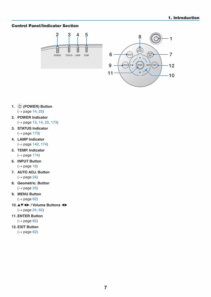
Control Panel/Indicator Section
11 10
7
2 3 4 5 8 1
6
129
1. (POWER)Button (→page14,25)
2. POWER Indicator (→page13,14,25,173)
3. STATUS Indicator (→page173)
4. LAMP Indicator (→page142,174)
5. TEMP. Indicator (→page174)
6. INPUTButton (→page16)
7. AUTO ADJ. Button (→page24)
8. Geometric. Button (→page33)
9. MENU Button (→page62)
10.▲▼◀▶/VolumeButtons◀▶ (→page24,62)
11. ENTER Button (→page62)
12. EXIT Button (→page62)

8
1. Introduction
Terminal Panel Features
2 3112 8 910 11
7
4
5 15 1613 14 6
1. HDMI1INConnector(TypeA) (→page126,128,132,171)
2. HDMI2INConnector(TypeA) (→page126,128,132,171)
3. DisplayPortINConnector (→page126,171)
4. BNCIN[R/Cr/CV,G/Y/Y,B/Cb/C,H,V]Connec-tors(BNC×5)
(→page125,130)
5. BNC(CV)InputConnector(BNC×1) (→page130)
6. BNC(Y/C)InputConnector(BNC×2) (→page130)
7. BNCAUDIOINMiniJack(StereoMini) (→page128,130)
8. COMPUTERIN/ComponentInputConnector(MiniD-Sub15Pin)
(→page13,125)
9. COMPUTERAUDIOINMiniJack(StereoMini) (→page13,125)
10.Ethernet/HDBaseTPort(RJ-45) (→page133,172)
11.USB-APort(TypeA) (→page172) (Forfutureexpansion.Thisportallowsforpowersup-ply.)
12.HDMIOUTConnector(TypeA) (→page129)
13.AUDIOOUTMiniJack(StereoMini) (→page129)
14.3DSYNCConnector(MiniDIN4Pin) (→page39)
15.PCCONTROLPort(D-Sub9Pin) (→page172) Use this port to connect aPC or control system.Thisenablesyoutocontroltheprojectorusingserialcommunicationprotocol.Ifyouarewritingyourownprogram,typicalPCcontrolcodesareonpage178.
16.REMOTEConnector(StereoMini) Use this connector forwired remote control of theprojectorusingtheNECoptionalremotecontrol.
Connect the projector andoptional remote controlusingacommerciallyavailablewiredremotecontrolcable.
NOTE: • Whenaremotecontrolcable isconnectedtotheREMOTE
connector, infrared remote control operations cannot be performed.
• When [HDBaseT] is selected in the [REMOTE SENSOR]and the projector is connected to a commercially-available transmissiondevicethatsupportsHDBaseT,remotecontroloperations in infra-red cannot be carried out if transmission of remote control signals has been set up in the transmission device.However,remotecontrolusinginfraredrayscanbecarried out when the power supply of the transmission device is switched off.

9
1. Introduction
❹ Part Names of the Remote Control
8. TEST Button (→page70)
9. Edge Blend. Button (→page91)
10.Multi.Button (→page92)
11. Geometric. Button (→page33)
12. INPUT Button (→page16)
13. PIP Button (→page53)
14.PBP/POPButton (→page53)
15. AUTO ADJ. Button (→page24)
16.1(HDMI1)Button (→page16)
17.2(HDMI2)Button (→page16)
18.3(DisplayPort)Button (→page16)
19.4(BNC)Button (→page16)
20.5(BNC(CV))Button (→page16)
21.6(BNC(Y/C))Button (→page16)
22.7(Computer)Button (→page16)
23.8(HDBaseT)Button (→page16)
24.9(USB-A)Button (→page16)
25. ID SET Button (→page105)
26.NumericKeypadButton/CLEAR Button
(→page105)
27. MENU Button (→page62)
28. EXIT Button (→page62)
1. Infrared Transmitter (→page11)
2. POWER ON Button (→page14)
3. STANDBY Button (→page25)
4. FREEZE Button (→page28)
5. BLANKButton (→page27)
6. MUTEButton (→page27)
7. AV-MUTEButton (→page27)
29. ▲▼◀▶ Button (→page62)
30.ENTERButton (→page62)
31.L-CLICKButton* (→page32)
32.R-CLICKButton* (→page32)
33.VOL./FOCUS(+)(−)Button (→page24)
34.D-ZOOM/ZOOM(+)(−)Button (→page28) (“ZOOM”Buttondoesnotworkonthisseriesofprojectors)
35. SHUTTER Button (not available on this series ofprojectors)
36.LENSSHIFTButton (not available on this series ofprojectors)
37. PICTURE Button (→page74,76)
38. DISPLAY Button (→page85)
39. ASPECT Button (→page80)
40.COLORButton (→page76)
41. 3D Set. Button (→page39)
42. SETUP Button (→page94)
43. CTL Button (→page31,32)
44. ECO Button (→page29)
45. INFO Button (→page118)
46.HELPButton (→page118)
1
35489
1213
26711101514
16
1922
2523
17
27
31
33
35
30
21
28
29
20
32
2426
18
34
36
43
44
4645
374038
4241
39
* The▲▼◀▶,L-CLICKandR-CLICKbuttonsworkonlywhenaUSBcableisconnectedwithyourcomputer.

10
1. Introduction
Battery Installation1. Press the catch and remove
the battery cover.2. Install new ones (AA). En-
sure that you have the bat-teries’ polarity (+/−) aligned correctly.
3. Slip the cover back over the batteries until it snaps into place.
NOTE:Donotmixdifferenttypesofbatteriesornewand old batteries.
1
2 12
Remote Control Precautions
• Handletheremotecontrolcarefully.
• Iftheremotecontrolgetswet,wipeitdryimmediately.
• Avoidexcessiveheatandhumidity.
• Donotshort,heat,ortakeapartbatteries.
• Donotthrowbatteriesintofire.
• Ifyouwillnotbeusingtheremotecontrolforalongtime,removethebatteries.
• Ensurethatyouhavethebatteries’polarity(+/−)alignedcorrectly.
• Donotusenewandoldbatteriestogether,orusedifferenttypesofbatteriestogether.
• Disposeofusedbatteriesaccordingtoyourlocalregulations.

11
1. Introduction
Operating Range for Wireless Remote Control
40m/1575inch
40m/1575inch
Remotecontrol
Remotesensoronprojectorcabinet
40m/1575inch
40m/1575inch
20m/787inch
20m/787inch
20m/787inch
20m/787inch
15m/591inch
15m/591inch
15m/591inch
15m/591inch
• Theinfraredsignaloperatesbyline-of-sightuptoadistanceofabovemetersandwithina60-degreeangleoftheremotesensorontheprojectorcabinet.
• Theprojectorwillnotrespondifthereareobjectsbetweentheremotecontrolandthesensor,orifstronglightfallsonthesensor.Weakbatterieswillalsopreventtheremotecontrolfromproperlyoperatingtheprojector.

12
Thissectiondescribeshowtoturnontheprojectorandtoprojectapictureontothescreen.
❶ Flow of Projecting an Image
Step 1• Connectingyourcomputer/Connectingthepowercord(→ page 13)
Step 2 • Turningontheprojector(→ page 14)
Step 3 • Selectingasource(→ page 16)
Step 4• Adjustingthepicturesizeandposition(→ page 18)
• Correctingkeystonedistortion[KEYSTONE](→ page 33)
Step 5• Adjustingapictureandsound
- Optimizingacomputersignalautomatically(→page24)
- Turningupordownvolume(→page24)
Step 6• Makingapresentation
Step 7• Turningofftheprojector(→ page 25)
Step 8• Afteruse(→ page 26)
2. Projecting an Image (Basic Operation)

13
2. Projecting an Image (Basic Operation)
❷ Connecting Your Computer/Connecting the Power Cord
1. Connectyourcomputertotheprojector.
Thissectionwillshowyouabasicconnectiontoacomputer.Forinformationaboutotherconnections,see“(2)MakingConnections”onpage125.
Connectthedisplayoutputterminal(miniD-sub15pin)onthecomputertothecomputervideoinputterminalontheprojectorwithacommercially-availablecomputercable(withferritecore)andthenturntheknobsofthecon-nectorstosecurethem.
2. Connectthesuppliedpowercordtotheprojector.
Firstconnectthesuppliedpowercord’sthree-pinplugtotheACINoftheprojector,andthenconnecttheotherplugofthesuppliedpowercordinthewalloutlet.
Uponconnectingthepowercable,thePOWERindicatoroftheprojectorwilllightupinorange.Iftherearenoinputsignals,thedevicewillgointothestandbymodeafterabout10secondsandlightupinred*.
TheSTATUSindicatorwilllightoff*.
*Thiswillapplyforbothindicatorswhen[NORMAL]isselectedfor[STANDBYMODE].SeethePowerIndicatorsection.(→page173)
COMPUTER IN
MakesurethattheprongsarefullyinsertedintoboththeACINandthewalloutlet.
Towalloutlet
Computercable(withferritecore)(soldcommercially)
CAUTION:PartsoftheprojectormaybecometemporarilyheatediftheprojectoristurnedoffwiththePOWERbuttonoriftheACpowersupplyisdisconnectedduringnormalprojectoroperation.Usecautionwhenpickinguptheprojector.

14
2. Projecting an Image (Basic Operation)
Standby Blinking Power On
Steady red light Blinking blue light
Steady blue light
❸ Turning on the Projector
1. Remove the lens cap.
2. Press the (POWER) button on the projector cabinet or the POWER ON button on the remote control.
ThePOWERindicatorwill lightup inblue fromredandthenstartblinking.Afterthat,theimagewillbeprojectedontothescreen.
TIP: • Whenthemessage“PROJECTORISLOCKED!ENTERYOUR
PASSWORD.” is displayed, it means that the [SECURITY]feature is turned on. (→ page 36)
• When the ECO message is displayed, it means that [ON] isselectedfor[ECOMESSAGE].(→ page 95)
• PressingbuttonssuchaspowerbuttonandMENUbuttonwillmakesound.Toturnoffthebeepsound,select[OFF]for[BEEP]from the menu. (→ page 106)
Afteryouturnonyourprojector,ensurethatthecomputerorvideosourceisturnedon.
NOTE: A blue screen (blue background) is displayed when no signal is being input (by factory default menu settings).
(→page173)
15
2. Projecting an Image (Basic Operation)
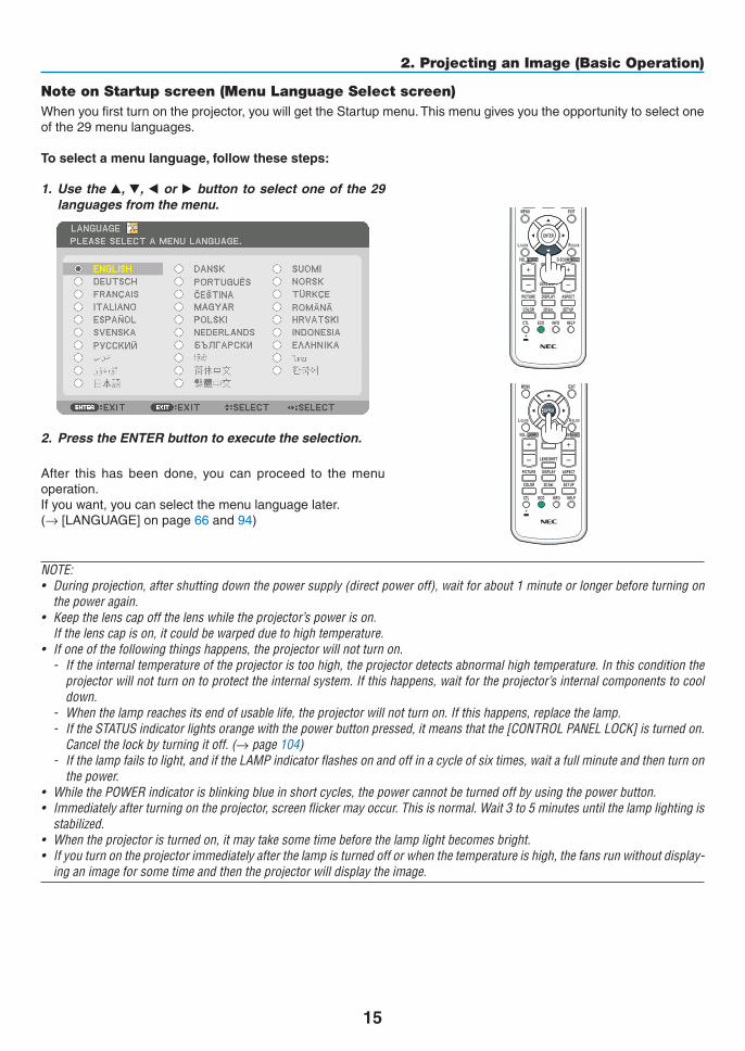
Note on Startup screen (Menu Language Select screen)Whenyoufirstturnontheprojector,youwillgettheStartupmenu.Thismenugivesyoutheopportunitytoselectoneofthe29menulanguages.
Toselectamenulanguage,followthesesteps:
1. Use the ▲, ▼, ◀ or ▶ button to select one of the 29 languages from the menu.
2. Press the ENTER button to execute the selection.
After this has been done, you can proceed to themenuoperation.Ifyouwant,youcanselectthemenulanguagelater.(→[LANGUAGE]onpage66and94)
NOTE: • Duringprojection,aftershuttingdownthepowersupply(directpoweroff),waitforabout1minuteorlongerbeforeturningon
the power again.• Keepthelenscapoffthelenswhiletheprojector’spowerison. If the lens cap is on, it could be warped due to high temperature.• Ifoneofthefollowingthingshappens,theprojectorwillnotturnon.
- If the internal temperature of the projector is too high, the projector detects abnormal high temperature. In this condition the projectorwillnotturnontoprotecttheinternalsystem.Ifthishappens,waitfortheprojector’sinternalcomponentstocooldown.
- Whenthelampreachesitsendofusablelife,theprojectorwillnotturnon.Ifthishappens,replacethelamp.- IftheSTATUSindicatorlightsorangewiththepowerbuttonpressed,itmeansthatthe[CONTROLPANELLOCK]isturnedon.
Cancelthelockbyturningitoff.(→ page 104)- Ifthelampfailstolight,andiftheLAMPindicatorflashesonandoffinacycleofsixtimes,waitafullminuteandthenturnon
the power.• WhilethePOWERindicatorisblinkingblueinshortcycles,thepowercannotbeturnedoffbyusingthepowerbutton.• Immediatelyafterturningontheprojector,screenflickermayoccur.Thisisnormal.Wait3to5minutesuntilthelamplightingis
stabilized.• Whentheprojectoristurnedon,itmaytakesometimebeforethelamplightbecomesbright.• Ifyouturnontheprojectorimmediatelyafterthelampisturnedofforwhenthetemperatureishigh,thefansrunwithoutdisplay-
ing an image for some time and then the projector will display the image.

16
2. Projecting an Image (Basic Operation)
❹ Selecting a SourceSelecting the computer or video sourceNOTE: Turn on the computer or video source equipment connected to the projector.
DetectingtheSignalAutomaticallyPresstheINPUTbuttonfor1secondorlonger.Theprojectorwillsearchfortheavailableinputsourceanddisplayit.Theinputsourcewillchangeasfollows:
HDMI1→HDMI2→DisplayPort→BNC→BNC(CV)→BNC(Y/C)→ COMUPTER→HDBaseT→HDMI1→ …
• Pressitbrieflytodisplaythe[INPUT]screen.
Pressthe▼/▲buttonstomatchthetargetinputterminalandthenpresstheENTERbuttontoswitchtheinput.Todeletethemenudisplayinthe[INPUT]screen,presstheMENUorEXITbutton.
TIP: If no input signal is present, the input will be skipped.
Using the Remote ControlPress any oneof the 1/HDMI 1, 2/HDMI 2, 3/DisplayPort, 4/BNC, 5/BNC(CV),6/BNC(Y/C),7/Computer,or8/HDBaseTbuttons.

17
2. Projecting an Image (Basic Operation)
Selecting Default Source Youcansetasourceasthedefaultsourcesothatitwillbedisplayedeachtimetheprojectoristurnedon.
1. Press the MENU button.
Themenuwillbedisplayed.
2. Press the ▶buttontoselect[SETUP]andpressthe▼buttonortheENTERbuttontoselect[BASIC].
3. Press the ▶buttontoselect[SOURCEOPTIONS].
4. Press the ▼buttonfourtimestoselect[DEFAULTINPUTSELECT]andpresstheENTERbutton.
The[DEFAULTINPUTSELECT]screenwillbedisplayed.
(→page112)
5. Select a source as the default source, and press the ENTER button.
6. Press the EXIT button a few times to close the menu.
7. Restart the projector.
Thesourceyouselectedinstep5willbeprojected.
NOTE:Evenwhen[AUTO]isturnedon,the[HDBaseT]willnotbeautomaticallyselected.Tosetyournetworkasthedefaultsource,select[HDBaseT].
TIP: • WhentheprojectorisinStandbymode,applyingacomputersignalfromacomputerconnectedtotheCOMPUTERINinputwill
powerontheprojectorandsimultaneouslyprojectthecomputer’simage. ([AUTOPOWERONSELECT]→ page 115)• OntheWindows7keyboard,acombinationoftheWindowsandPkeysallowsyoutosetupexternaldisplayeasilyandquickly.
18
2. Projecting an Image (Basic Operation)
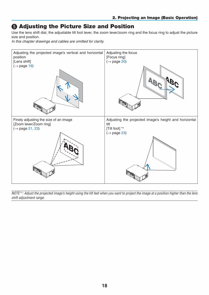
❺ Adjusting the Picture Size and PositionUsethelensshiftdial,theadjustabletiltfootlever,thezoomlever/zoomringandthefocusringtoadjustthepicturesizeandposition.Inthischapterdrawingsandcablesareomittedforclarity.
Adjusting theprojected image’sverticalandhorizontalposition[Lensshift](→page19)
Adjustingthefocus[Focusring](→page20)
Finelyadjustingthesizeofanimage[Zoomlever/Zoomring](→page21,23)
Adjusting the projected image’s height and horizontaltilt[Tiltfoot]*¹(→page23)
NOTE*1:Adjusttheprojectedimage’sheightusingthetiltfeetwhenyouwanttoprojecttheimageatapositionhigherthanthelensshift adjustment range.

19
2. Projecting an Image (Basic Operation)
Adjusting the vertical position of a projected image (Lens shift)
CAUTIONPerformtheadjustmentfrombehindorfromthesideoftheprojector.Adjustingfromthefrontcouldexposeyoureyestostronglightwhichcouldinjurethem.
Downward
Upward
Lensshiftdial(Horizontal)
Lensshiftdial(Vertical)
RightwardLeftward
• Turnthelensshiftdialsclockwiseorcounterclockwise.
VerticaldialTurnthisclockwiseorcounterclockwisetoadjusttheprojectionpositionintheverticaldirection.Approximateturningrange:About6turnscounterclockwise,about2turnsclockwisewhenthelensisatthecenterposition.
HorizontaldialTurnthisclockwiseorcounterclockwisetoadjusttheprojectionpositioninthehorizontaldirection.Approximateturningrange:About1 turncounterclockwise,about1 turnclockwisewhenthe lens isat thecenterposition.
NOTE:• Thedialscanbeturnedmorethanonefullturn,buttheprojectionpositioncannotbemovedmorethantherangeindicatedon
the following page.• Ifthelensisshiftedtothemaximuminthediagonaldirection,theedgesofthescreenwillbedarkorshaded.• Theverticalshiftadjustmentmustbefinishedwithanimageshiftedupward.Ifyoufinishtheverticalshiftadjustmentwithan
image shifted down, the zoom/focus adjustments or strong shaking may cause a projected image to slightly shift down.• ThelensshiftfunctioncannotbeusedwhenusingtheseparatelysoldNP11FLlens.

20
2. Projecting an Image (Basic Operation)
TIP: • ThediagrambelowshowsthelensshiftadjustmentrangeforthePA622UandPA522U(projectionmode:desktopfront).Toraise
the projection position higher than this, use the tilt feet. (→ page 23)• ForthePA672W/PA572W/PA722X/PA622Xandtheceilingmount/frontprojectionlensshiftadjustmentrange,seepage162,
163.
100%V
50%V
10%V100%H30%H 30%H
10%H 10%H
Heightofprojectedimage
Widthofprojectedimage
PA622U/PA522U
Descriptionofsymbols:Vindicatesvertical(heightoftheprojectedimage),Hindicateshorizontal(widthoftheprojectedim-age).
FocusApplicablelens:NP12ZL/NP13ZL/NP14ZL/NP15ZLUsetheFOCUSringtoobtainthebestfocus.
Focusring

21
2. Projecting an Image (Basic Operation)
Applicable lens: NP30ZLTheNP30ZLlensunitalignstheperipheralfocusaroundtheopticalaxis.
Peripheralfocusring
FocusRing
ZoomLever
1. Turn the focus ring left and right to align the focus around the optical axis.
* Thediagramshowsanexamplewhenthelensshiftismovedtothetop.Thetopofthescreenisadjusted.
Whenthelensisinthecenter,thecenterofthescreenisadjusted.
FocusRing
Opticalaxis
2. Turn the peripheral focus ring to the left and right to align the focus of the overall screen.
Atthispoint,thefocusaroundtheopticalaxisadjustedin(1)remainsunchanged. Peripheralfocus
ring

22
2. Projecting an Image (Basic Operation)
Applicable lens: NP11FLWiththeNP11FLlens,adjustthefocusandpicturedistortion.Preparations:Turnthelensshiftdials(verticalandhorizontal)ontheprojectortoreturnthelensshifttothecenter.Approximatelenscenterposition(explainedhereforthedesktopfrontprojectionmode)
Horizontal dial �������� First turn the dial to the left edge, then turn it further so that the knob is horizontal� From this position, turn the dial 1 full turn clockwise�
Vertical dial ������������ First turn the dial to the bottom edge, then turn it further so that the knob is horizontal�From this position, turn the dial 2 full turns counterclockwise�
1. Turn the distortion ring to the left edge.
Distortionring
Lensshiftdials
2. Turn the focus lever clockwise and counterclockwise to adjust the focus at the center of the screen.
Focuslever
3. Use the distortion ring to correct the screen’s distor-tion.
(Thisalsobringstheedgesofthescreenintofocus.)
4. Use the focus lever to adjust the screen’s overall fo-cus.
* If thefocusat thecenterof thescreen isoff, turnthedistortionringalittlecounterclockwise.Thefocusatthecenterofthescreencannowbeadjustedwiththefocuslever.

23
2. Projecting an Image (Basic Operation)
Adjusting the Tilt Feet1. Turn the left and right tilt feet to adjust.
Thetiltfeetlengthenandshortenwhenturned.
Theheightoftheprojectedimageisadjustedbyturningtheleftandrighttiltfeet.
If theprojectedimageistilted,turnoneofthetilt feet toadjust theimagesothatitislevel.
• Iftheprojectedimageisdistorted,see“3-6CorrectingHorizontalandVerticalKeystoneDistortion[CORNERSTONE]”(→page33) and“[GEOMETRICCORRECTION]”(→page87).
• Thetiltfeetcanbelengthenedbyamaximumof20mm.
• Thetiltfeetcanbeusedtotilttheprojectorbyamaximumof4º.
NOTE:• Donotlengthenthetiltfeetanymorethan20mm/0.8".Doingsowillmakethe
tiltfeet’smountsectionunstableandcouldcausethetiltfeettocomeofftheprojector.
• Donotuse the tilt feet foranypurposeother thanadjusting theprojector’sprojection angle.
Handlingthetiltfeetimproperly,suchascarryingtheprojectorbygraspingthetilt feet or hooking it onto a wall using the tilt feet, could damage the projec-tor.
ZoomTurnthezoomleverorzoomringclockwiseandcounterclockwise.• TheseparatelysoldNP11FLlensdoesnothaveazoomring.
Zoomring
Up
Tiltfoot
Down

24
2. Projecting an Image (Basic Operation)
❻ Optimizing Computer Signal AutomaticallyAdjusting the Image Using Auto AdjustOptimizingacomputerimageautomatically.(COMPUTER/BNC(AnalogRGB))PresstheAUTOADJ.buttontooptimizeacomputerimageautomatically.Thisadjustmentmaybenecessarywhenyouconnectyourcomputerforthefirsttime.
[Poorpicture]
[Normalpicture]
NOTE:Somesignalsmaytaketimetodisplayormaynotbedisplayedcorrectly.• IftheAutoAdjustoperationcannotoptimizethecomputersignal,trytoadjust[HORIZONTAL],[VERTICAL],[CLOCK],and[PHASE]
manually. (→ page 78, 79)
❼ Turning Up or Down VolumeSoundlevelfromthespeakercanbeadjusted.
TIP:Whennomenusappear,the◀ and ▶ buttons on the projector cabinet work as a volume control.
NOTE:• Volumecontrolisnotavailablewiththe◀ or ▶ button when an image is enlarged
byusingtheD-ZOOM(+)buttonorwhenthemenuisdisplayed.
Increasevolume
Decreasevolume

25
2. Projecting an Image (Basic Operation)
❽ Turning off the Projector
To turn off the projector:1. First, press the (POWER) button on the projector
cabinet or the POWER OFF button on the remote con-trol.
The[POWEROFF/AREYOUSURE?/CARBONSAV-INGS-SESSION0.000[g-CO2]]messagewillappear.
2. Secondly, press the ENTER button or press the (POWER) or the POWER OFF button again.
Thelampwillgooffandthepowersupplywillbecut.Atthispoint,iftherearenoinputsignals,theprojectorwillgointo thestandbymodeafterabout10seconds.When instandbymode,thePOWERindicatorwilllightredandtheSTATUSindicatorwilllightoffwhen[NORMAL]isselectedfor[STANDBYMODE].
Power On
Steady blue light
Standby
Steady red lightPress twice
CAUTION:PartsoftheprojectormaybecometemporarilyheatediftheprojectoristurnedoffwiththePOWERbuttonoriftheACpowersupplyisdisconnectedduringnormalprojectoroperation.Usecautionwhenpickinguptheprojector.
NOTE:• WhilethePOWERindicatorisblinkingblueinshortcycles,thepowercannotbeturnedoff.• Youcannotturnoffthepowerfor60secondsimmediatelyafterturningitonanddisplayinganimage.• Donotunplugthepowercordfromtheprojectororfromthepoweroutletwhileanimageisbeingprojected.Doingsocould
deterioratetheprojector’sACinputconnectororthepowerplug’scontact.ToturnofftheACpowerwhileanimageisbeingprojected,usethepowerstrip’sswitch,thebreaker,etc.
• DonotdisconnecttheACpowersupplytotheprojectorwithin10secondsofmakingadjustmentorsettingchangesandclosingthemenu.Doingsocancauselossofadjustmentsandsettings.

26
2. Projecting an Image (Basic Operation)
❾ After UsePreparation:Makesurethattheprojectoristurnedoff.
1. Unplug the power cord.
2. Disconnect any other cables.
3. Mount the lens cap on the lens.
4. Before moving the projector, screw in the tilt feet if they have been lengthened.

27
❶ Turning off the Image and SoundTheprojectedvideoandtheoutputsoundfromtheinternalspeakerandsoundoutputterminalwilldisappearmomentarily.
PresstheBLANKbutton.Theprojectedvideowillbecutoff.
Press the MUTE button.Theprojectedaudiowillbecutoff.
PresstheAV-MUTEbutton.Theprojectedvideoandaudiowillbecutoff.
• Pressthebuttonsonemoretimeforthecancelledvideoandaudiotoappearagain. WhenAV-MUTEandBLANKarecontinuedforsometime,theenergy-savingfunctionwillactivatetolowerthelamppower.
NOTE: • When the AV-MUTE and BLANK buttons are pressed immediately after the
energy-saving function is activated, sometimes the brightness may not return to normal immediately.
TIP:• Thevideowilldisappearbutnotthemenudisplay.
3. Convenient Features

28
3. Convenient Features
❷ Freezing a PicturePress theFREEZEbutton to freezeapicture.Pressagain to resumemotion.
NOTE: The image is frozen but the original video is still playing back.
❸ Enlarging a PictureYoucanenlargethepictureuptofourtimes.
NOTE:Themaximummagnificationmaybelessthanfourtimesdependingonthe signal.
Todoso:
1. Press the D-ZOOM (+) button to magnify the picture.
2. Press the ▲▼◀▶ button. Theareaofthemagnifiedimagewillbemoved
3. Press the D-ZOOM (−) button.
EachtimetheD-ZOOM(−)buttonispressed,theimageisreduced.
NOTE: • Theimagewillbeenlargedorreducedatthecenterofthescreen.• Displayingthemenuwillcancelthecurrentmagnification.

29
3. Convenient Features
❹ Changing Eco Mode/Checking Energy-Saving Effect Using Eco Mode [ECO MODE]Thisfeatureenablesyoutoselecttwobrightnessmodesofthelamp:OFFandONmodes.Thelamplifecanbeextendedbyturningonthe[ECOMODE].
[ECOMODE] Description
[OFF] Thisisthedefaultsetting(100%Brightness).
[ON] Lowlamppowerconsumption(approx.80%Brightness).
Toturnonthe[ECOMODE],dothefollowing:1. PresstheECObuttonontheremotecontroltodisplay[ECOMODE]screen.
2. Use the ▲ or ▼buttontoselect[ON].
3. Press the ENTER button.
Tochangefrom[ON]to[OFF],GobacktoStep2andselect[OFF].RepeatStep3.
NOTE: • The[ECOMODE]canbechangedbyusingthemenu. Select[SETUP]→[INSTALLATION]→[LAMPMODE]→[ECOMODE].• Thelampliferemainingandlamphoursusedcanbecheckedin[USAGETIME].Select[INFO.]→[USAGETIME].• [ECOMODE]isalwayssetto[OFF]for1minuteimmediatelyafterthelampisturnedon.Thelampconditionwillnotbeaffected
evenwhen[ECOMODE]ischanged.• Afteralapseof1minutefromwhentheprojectordisplaysablue,blackorlogoscreen,[ECOMODE]willautomaticallyswitchto
[ON].• Iftheprojectorisoverheatedin[OFF]mode,theremaybeacasewherethe[ECOMODE]automaticallychangesto[ON]mode
toprotecttheprojector.Thisiscalled“ForcedECOMode”.WhentheprojectorisintheForcedEcoMode,thepicturebrightnessdecreasesslightlyandtheTEMP.indicatorlightsorange.AtthesametimetheThermometersymbol[ ]isdisplayedatthebot-tom right of the screen.
Whentheprojectorcomesbacktonormaltemperature,theForcedEcoModeiscancelledandthe[ECOMODE]returnsto[OFF]mode.
30
3. Convenient Features
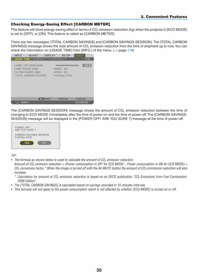
Checking Energy-Saving Effect [CARBON METER]Thisfeaturewillshowenergy-savingeffectintermsofCO2emissionreduction(kg)whentheprojector’s[ECOMODE]issetto[OFF],or[ON].Thisfeatureiscalledas[CARBONMETER].
Therearetwomessages:[TOTALCARBONSAVINGS]and[CARBONSAVINGS-SESSION].The[TOTALCARBONSAVINGS]messageshowsthetotalamountofCO2emissionreductionfromthetimeofshipmentuptonow.Youcanchecktheinformationon[USAGETIME]from[INFO.]ofthemenu.(→page118)
The[CARBONSAVINGS-SESSION]messageshowstheamountofCO2emissionreductionbetweenthetimeofchangingtoECOMODEimmediatelyafterthetimeofpower-onandthetimeofpower-off.The[CARBONSAVINGS-SESSION]messagewillbedisplayedinthe[POWEROFF/AREYOUSURE?]messageatthetimeofpower-off.
TIP:• TheformulaasshownbelowisusedtocalculatetheamountofCO2 emission reduction. AmountofCO2emissionreduction=(PowerconsumptioninOFFforECOMODE−PowerconsumptioninONforECOMODE)×
CO2conversionfactor.*WhentheimageisturnedoffwiththeAV-MUTEbuttontheamountofCO2 emmission reduction will also increase.* CalculationforamountofCO2emissionreductionisbasedonanOECDpublication“CO2EmissionsfromFuelCombustion,
2008Edition”.• The[TOTALCARBONSAVINGS]iscalculatedbasedonsavingsrecordedin15minutesintervals.• Thisformulawillnotapplytothepowerconsumptionwhichisnotaffectedbywhether[ECOMODE]isturnedonoroff.

31
3. Convenient Features
❺ Using the Optional Remote Mouse Receiver (NP01MR)Theoptionalremotemousereceiverenablesyoutooperateyourcomputer’smousefunctionsfromtheremotecontrol.Itisagreatconvenienceforclickingthroughyourcomputer-generatedpresentations.
ConnectingtheremotemousereceivertoyourcomputerIfyouwishtousetheremotemousefunction,connectthemousereceiverandcomputer.Themousereceivercanbeconnecteddirectlytothecomputer’sUSBport(typeA).
NOTE:DependingonthetypeofconnectionorOSinstalledonyourcomputer,youmayhavetorestartyourcomputerorchangeyour computer settings.
When operating a computer via the remote mouse receiver
When connecting using the USB terminalForPC,themousereceivercanonlybeusedwithaWindowsXP*,WindowsVista,Windows7,orMacOSX10.0.0orlateroperatingsystem.
*NOTE:InSP1orolderversionofWindowsXP,ifthemousecursorwillnotmovecorrectly,dothefollowing:CleartheEnhancepointerprecisioncheckboxunderneaththemousespeedsliderintheMousePropertiesdialogbox[PointerOptionstab].
NOTE:WhenusingPowerPointforMacOS,theCTLbuttonandthepage▼/▲ buttons (page up and down) on the remote control will be disabled.
NOTE:Waitatleast5secondsafterdisconnectingthemousereceiverbeforereconnectingitandviceversa.Thecomputermaynotidentify the mouse receiver if it is repeatedly connected and disconnected in rapid intervals.
Remotemousereceiver
Computer
ToUSBportofPCorMac
Remotesensorontheremotemousereceiver
7m/22feet

32
3. Convenient Features
Operatingyourcomputer’smousefromtheremotecontrolYoucanoperateyourcomputer’smousefromtheremotecontrol.
CTL Button + PAGE ▼/▲ Button ������������������������������ scrolls the viewing area of the window or to move to the previous or next slide in PowerPoint on your
computer�▲▼◀▶ Buttons ���� moves the mouse cursor on your computer�L-CLICK Button ������ works as the mouse left button�R-CLICK Button ����� works as the mouse right button�
NOTE:• Whenyouoperatethecomputerusingthe▲▼◀ or ▶ button with the menu displayed, both the menu and the mouse pointer
willbeaffected.Closethemenuandperformthemouseoperation.• WhenusingPowerPointforMacOS,theCTLbuttonandthepage▼/▲ buttons (page up and down) on the remote control will
be disabled.
About Drag Mode:BypressingtheL-CLICKorR-CLICKbuttonfor2or3secondsthenreleasing,thedragmodeissetandthedragoperationcanbeperformedsimplybypressingthe▲▼◀▶button.Todroptheitem,presstheL-CLICK(orR-CLICK)button.Tocancelit,presstheR-CLICK(orL-CLICK)button.
TIP:YoucanchangethePointerspeedontheMousePropertiesdialogboxontheWindows.Formoreinformation,seetheuserdocumentation or online help supplied with your computer.

33
3. Convenient Features
❻ Correcting Horizontal and Vertical Keystone Distortion [COR-NERSTONE]
Usethe[CORNERSTONE]featuretocorrectkeystone(trapezoidal)distortiontomakethetoporbottomandtheleftorrightsideofthescreenlongerorshortersothattheprojectedimageisrectangular.
1. Press and hold the Geometric. button for a minimum of 2 seconds to reset current adjustments.
Currentadjustmentsfor[GEOMETRICCORRECTION]willbecleared.
2. Project an image so that the screen is smaller than the area of the raster.
Projectedimage
Thedrawingshowstheupperrightcorner.
3. Pick up any one of the corners and align the corner of the image with a corner of the screen.
4. Press the Geometric. button.
Displaythe[GEOMETRICCORRECTION]screenoftheon-screenmenu.
34
3. Convenient Features
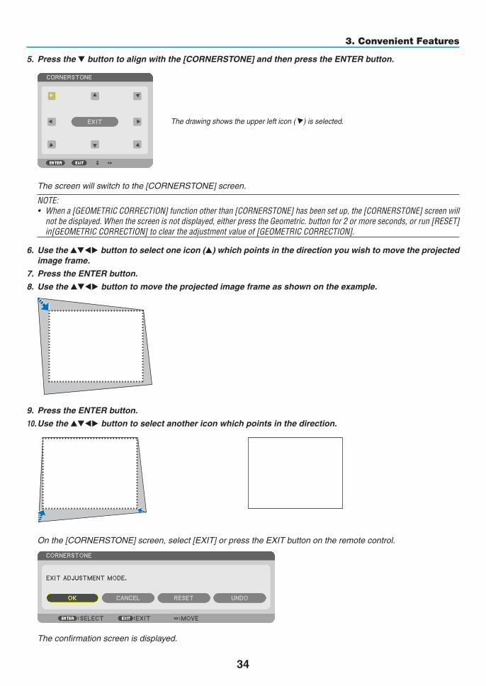
5. Press the ▼buttontoalignwiththe[CORNERSTONE]andthenpresstheENTERbutton.
Thedrawingshowstheupperlefticon( )isselected.
Thescreenwillswitchtothe[CORNERSTONE]screen.
NOTE:• Whena[GEOMETRICCORRECTION]functionotherthan[CORNERSTONE]hasbeensetup,the[CORNERSTONE]screenwill
notbedisplayed.Whenthescreenisnotdisplayed,eitherpresstheGeometric.buttonfor2ormoreseconds,orrun[RESET]in[GEOMETRICCORRECTION]tocleartheadjustmentvalueof[GEOMETRICCORRECTION].
6. Use the ▲▼◀▶ button to select one icon (▲) which points in the direction you wish to move the projected image frame.
7. Press the ENTER button.
8. Use the ▲▼◀▶ button to move the projected image frame as shown on the example.
9. Press the ENTER button.
10. Use the ▲▼◀▶ button to select another icon which points in the direction.
Onthe[CORNERSTONE]screen,select[EXIT]orpresstheEXITbuttonontheremotecontrol.
Theconfirmationscreenisdisplayed.

35
3. Convenient Features
11. Press the ◀ or ▶buttontohighlightthe[OK]andpresstheENTERbutton.
Thiscompletesthe[CORNERSTONE]correction.
• Select[CANCEL]andpresstheENTERbuttontoreturntothe[CORNERSTONE]screen.
Selecting[CANCEL]willreturntotheadjustmentscreenwithoutsavingchanges(Step3).Selecting[RESET]willreturntothefactorydefault.Selecting[UNDO]willexitwithoutsavingchanges.
NOTE: • Evenwhentheprojectoristurnedon,thelastusedcorrectionvaluesareapplied.• Carryouteitheroneofthefollowingactionstocleartheadjustmentvalueof[CORNERSTONE].
• InStep11,select[RESET]andthenpresstheENTERbutton.• PresstheGeometric.buttonfor2ormoreseconds.• Run[DISPLAY]→[GEOMETRICCORRECTION]→[RESET]intheon-screenmenu.
• UsingCORNERSTONEcorrectioncancausetheimagetobeslightlyblurredbecausethecorrectionismadeelectronically.

36
3. Convenient Features
❼ Preventing the Unauthorized Use of the Projector [SECURITY]AkeywordcanbesetforyourprojectorusingtheMenutoavoidoperationbyanunauthorizeduser.Whenakeywordisset,turningontheprojectorwilldisplaytheKeywordinputscreen.Unlessthecorrectkeywordisentered,thepro-jectorcannotprojectanimage.•The[SECURITY]settingcannotbecancelledbyusingthe[RESET]ofthemenu.
ToenabletheSecurityfunction:
1. Press the MENU button.
Themenuwillbedisplayed.
2. Press the ▶ button twice to select [SETUP] and press the▼ button or the ENTER button to select [MENU].
3. Press the ▶buttontoselect[CONTROL].
4. Press the ▼buttonthreetimestoselect[SECURITY]andpresstheENTERbutton.
TheOFF/ONmenuwillbedisplayed.
5. Press the ▼buttontoselect[ON]andpresstheENTERbutton.
The[SECURITYKEYWORD]screenwillbedisplayed.
6. Type in a combination of the four ▲▼◀▶ buttons and press the ENTER button.
NOTE: A keyword must be 4 to 10 digits in length.
The[CONFIRMKEYWORD]screenwillbedisplayed.
NOTE:Makeanoteofyourpasswordandstoreitinasafeplace.

37
3. Convenient Features
7. Type in the same combination of ▲▼◀▶ buttons and press the ENTER button.
Theconfirmationscreenwillbedisplayed.
8. Select[YES]andpresstheENTERbutton.
TheSECURITYfunctionhasbeenenabled.
To turn on the projector when [SECURITY] is enabled:
1. Press the POWER button.
Theprojectorwillbeturnedonanddisplayamessagetotheeffectthattheprojectorislocked.
2. Press the MENU button.
3. Type in the correct keyword and press the ENTER button. The projector will display an image.
NOTE: The security disable mode is maintained until the main power is turned off or unplugging the power cord.

38
3. Convenient Features
To disable the SECURITY function:
1. Press the MENU button.
Themenuwillbedisplayed.
2.Select[SETUP]→[CONTROL]→[SECURITY]andpresstheENTERbutton.
TheOFF/ONmenuwillbedisplayed.
3. Select[OFF]andpresstheENTERbutton.
TheSECURITYKEYWORDscreenwillbedisplayed.
4. Type in your keyword and press the ENTER button.
Whenthecorrectkeywordisentered,theSECURITYfunctionwillbedisabled.
NOTE:Ifyouforgetyourkeyword,contactyourdealer.Yourdealerwillprovideyouwithyourkeywordinexchangeforyourrequestcode.YourrequestcodeisdisplayedintheKeywordConfirmationscreen.Inthisexample[NB52-YGK8-2VD6-K585-JNE6-EYA8]is a request code.

39
3. Convenient Features
❽ Projecting 3D videosThisprojectorcanbeusedtowatchvideosin3Dusingcommercially-availableactiveshutter-type3Deyewear.Inordertosynchronizethe3Dvideoandeyewear,acommercially-available3Demitterneedstobeconnectedtotheprojector(ontheprojectorside).The3Deyewearreceivesinformationfromthe3Demitterandperformsopeningandclosingontheleftandright.
CAUTION
Health precautionsBeforeuse,pleasemakesuretoreadanyhealthprecautionsthatmaybestatedintheoperatingmanualsenclosedwiththe3Deyewearand3Dvideosoftware(Blu-rayplayer,games,computeranimationfiles,etc.).Pleasetakenoteofthefollowinginordertoavoidadversehealtheffects.• Pleasedonotusethe3Deyewearforpurposesotherthantowatch3Dvideos.• Pleasekeepadistanceofatleast2mawayfromthescreenwhenwatchingvideos.Watchingavideotooclosetothescreenwillincreaseeyefatigue.• Pleasedonotwatchvideoscontinuouslyforalongperiodoftime.Pleasetakea15minutes’breakaftereveryhourofwatching.• Pleaseconsultadoctorbeforewatchingifyouoranyofyourfamilymembershaveahistoryofsufferingfromseizurescausedbylightsensitivity.• Pleasestopwatchingimmediatelyandtakearestwhenyoufeelphysicallyunwellwhilewatching(vomiting,gid-diness,nausea,headaches,soreeyes,blurredvision,crampsanddumbnessinthelimbs,etc.).Pleaseconsultadoctorifthesymptomspersist.• Pleasewatcha3Dvideodirectlyinfrontofthescreen.Ifyouwatcha3Dvideoobliquelyfromthesides,thismayresultinphysicalandeyefatigue.
3Deyewearand3DemitterpreparationsPleaseuseanactiveshutter-type3DeyewearthatconformswiththeVESAstandard.Acommercially-availableRFtypemadebyXpandisrecommended.
3D eyewear ������������ Xpand X105-RF3D emitter Xpand ��� AD025-RF-X1
Procedure to watch 3D videos using this projector1. Connectthevideodevicetotheprojector.
2. Switch on the power supply to the projector.
3. Run the 3D video software and project the video using the projector.
Thishasbeenautomaticallysetupwhenshippedfromthefactory.Whena3Dvideocannotbeprojected,itmaybebecausethe3Ddetectionsignalsarenotincludedorbecausetheyarenotdetectablebytheprojector.
Pleasemanuallyselecttheformat.
4. Select the 3D video format.
(1)Pressthe“3DSet.”buttonontheremotecontrol.

40
3. Convenient Features
The[3DSETTINGS]screenwillbedisplayed.
(2)Pressthe▼buttontoalignthecursorwiththe[FORMAT]andpresstheENTERbutton.
Theformatscreenwillbedisplayed.
(3)Selecttheinputsignalformatusingthe▼buttonandthenpresstheENTERbutton.
The3Dsettingsscreenwilldisappearandthe3Dvideowillbeprojected.
PresstheMENUbuttonandtheon-screenmenuwilldisappear.
The3Dcautionmessagescreenwillbedisplayedwhenswitching toa3Dvideo (default factorysettingwhenshipped).Pleasereadthe“HealthPrecautions”onthepreviouspagetowatchvideosinthecorrectmanner.Thescreenwilldisappearafter60secondsorwhentheENTERbuttonispressed.(→page95)
5. Turn on the power supply of the 3D eyewear and wear the eyewear to watch the video.
Anormalvideowillbeshownwhena2Dvideoisinput.
Towatcha3Dvideoin2D,select[OFF(2D)]inthe[FORMAT]screenmentionedabovein(3).
NOTE:• Uponswitchingto3Dimage,thefollowingfunctionswillbecancelledanddisabled.[BLANKING],[PIP/PICTUREBYPICTURE],
[GEOMETRICCORRECTION],[EDGEBLENDING]([GEOMETRICCORRECTION]and[EDGEBLENDING]adjustmentvalueswillbe maintained.)
• Theoutputmaynotautomaticallyswitchtoa3Dvideodependingonthe3Dinputsignal.• ChecktheoperatingconditionsdescribedintheusermanualoftheBlu-rayplayer.• PleaseconnecttheDINterminalofthe3Demittertothe3DSYNCofthemainprojector.• The3Deyewearallowsvideostobeviewedin3Dbyreceivingsynchronizedopticalsignalsoutputfromthe3Demitter. Asaresult,the3Dimagequalitymaybeaffectedbyconditionssuchasthebrightnessofthesurroundings,screensize,viewing
distance, etc.• Whenplayinga3Dvideosoftwareonacomputer,the3DimagequalitymaybeaffectedifthecomputerCPUandgraphicschip
performance are low. Please check the required operating environment of the computer that is stated in the operating manual attachedtothe3Dvideosoftware.
• Dependingonthesignal,[FORMAT]and[L/RINVERT]maynotbeabletobeselected.Pleasechangethesignalinthatcase.
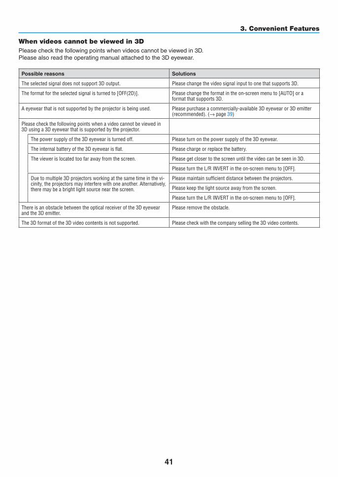
41
3. Convenient Features
When videos cannot be viewed in 3DPleasecheckthefollowingpointswhenvideoscannotbeviewedin3D.Pleasealsoreadtheoperatingmanualattachedtothe3Deyewear.
Possible reasons Solutions
The selected signal does not support 3D output� Please change the video signal input to one that supports 3D�
The format for the selected signal is turned to [OFF(2D)]� Please change the format in the on-screen menu to [AUTO] or a format that supports 3D�
A eyewear that is not supported by the projector is being used� Please purchase a commercially-available 3D eyewear or 3D emitter (recommended)� (→ page 39)
Please check the following points when a video cannot be viewed in 3D using a 3D eyewear that is supported by the projector�
The power supply of the 3D eyewear is turned off� Please turn on the power supply of the 3D eyewear�
The internal battery of the 3D eyewear is flat� Please charge or replace the battery�
The viewer is located too far away from the screen� Please get closer to the screen until the video can be seen in 3D�
Please turn the L/R INVERT in the on-screen menu to [OFF]�
Due to multiple 3D projectors working at the same time in the vi-cinity, the projectors may interfere with one another� Alternatively, there may be a bright light source near the screen�
Please maintain sufficient distance between the projectors�
Please keep the light source away from the screen�
Please turn the L/R INVERT in the on-screen menu to [OFF]�
There is an obstacle between the optical receiver of the 3D eyewear and the 3D emitter�
Please remove the obstacle�
The 3D format of the 3D video contents is not supported� Please check with the company selling the 3D video contents�
42
3. Convenient Features
❾ Controlling the Projector by Using an HTTP BrowserOverviewTheHTTPServerfunctionprovidessettingsandoperationsfor:1. Settingforwirednetwork(NETWORKSETTINGS)
TousewiredLANconnection,connecttheprojectortothecomputerwithacommerciallyavailableLANcable.(→ page137)
2. Setting Alert Mail (ALERT MAIL)
Whentheprojectorisconnectedtoawirednetwork,lampreplacetimeorerrormessageswillbesentviae-mail.
3. Operating the projector
Poweron/off,selectinginput,volumecontrolandpictureadjustmentsarepossible.
4. SettingPJLinkPASSWORDandAMXBEACON
AccesstotheHTTPserverfunctionisavailable:• StarttheWebbrowseronthecomputerviathenetworkconnectedtotheprojectorandenterthefollowing
URL :
http://<the projector’s IP address> /index.html
TIP:ThefactorysettingIPaddressis[DHCPON].
NOTE: • Tousetheprojectorinanetwork,consultwithyournetworkadministratoraboutnetworksettings.• Thedisplay’sorbutton’sresponsecanbesloweddownoroperationmaynotbeaccepteddependingthesettingsofyournet-
work. Shouldthishappen,consultyournetworkadministrator.Theprojectormaynotrespondifitsbuttonsarerepeatedlypressedin
rapidintervals.Shouldthishappen,waitamomentandrepeat.Ifyoustillcan’tgetanyresponse,turnoffandbackontheprojec-tor.
• IfthePROJECTORNETWORKSETTINGSscreendoesnotappearinthewebbrowser,presstheCtrl+F5keystorefreshyourwebbrowser (or clear the cache).
• Thisprojectoruses“JavaScript”and“Cookies”andthebrowsershouldbesettoacceptthesefunctions.Thesettingmethodwillvarydependingontheversionofbrowser.Pleaserefertothehelpfilesandtheotherinformationprovidedinyoursoftware.
Preparation before UseConnecttheprojectortoacommerciallyavailableLANcablebeforeengaginginbrowseroperations.(→page137)Operationwithabrowserthatusesaproxyservermaynotbepossibledependingonthetypeofproxyserverandthesettingmethod.Althoughthetypeofproxyserverwillbeafactor,itispossiblethatitemsthathaveactuallybeensetwillnotbedisplayeddependingontheeffectivenessofthecache,andthecontentssetfromthebrowsermaynotbereflectedinoperation.Itisrecommendedthataproxyservernotbeusedunlessitisunavoidable.

43
3. Convenient Features
Handling of the Address for Operation via a BrowserRegardingtheactualaddressthatisenteredfortheaddressorenteredtotheURLcolumnwhenoperationofthepro-jectorisviaabrowser,thehostnamecanbeusedasitiswhenthehostnamecorrespondingtotheIPaddressoftheprojectorhasbeenregisteredtothedomainnameserverbyanetworkadministrator,orthehostnamecorrespondingtotheIPaddressoftheprojectorhasbeensetinthe“HOSTS”fileofthecomputerbeingused.
Example1:Whenthehostnameoftheprojectorhasbeensetto“pj.nec.co.jp”,accessisgainedtothenetworksettingbyspecifying http://pj.nec.co.jp/index.html fortheaddressortheentrycolumnoftheURL.
Example2:WhentheIPaddressoftheprojectoris“192.168.73.1”,accessisgainedtothenetworksettingbyspecifying http://192.168.73.1/index.html fortheaddressortheentrycolumnoftheURL.
PROJECTOR ADJUSTMENT
POWER:Thiscontrolsthepoweroftheprojector.ON ������������������������� Power is switched on�OFF ������������������������ Power is switched off�
VOLUME:Thiscontrolsthevolumeoftheprojector.▲ ��������������������������� Increases the volume adjustment value�▼ ��������������������������� Decreases the volume adjustment value�
AV-MUTE:Thiscontrolsthemutefunctionoftheprojector.PICTURE ON ���������� Mutes the video�PICTURE OFF ��������� Cancels the video muting�SOUND ON ������������ Mutes the audio�SOUND OFF ����������� Cancels the audio muting�ALL ON ������������������ Mutes each of the video, and audio functions�ALL OFF ����������������� Cancels the muting of each of the video, and audio functions�

44
3. Convenient Features
PICTURE:Controlsthevideoadjustmentoftheprojector.BRIGHTNESS ▲ ���� Increases the brightness adjustment value�BRIGHTNESS ▼ ���� Decreases the brightness adjustment value�CONTRAST ▲ �������� Increases the contrast adjustment value�CONTRAST ▼ �������� Decreases the contrast adjustment value�COLOR ▲ �������������� Increases the color adjustment value�COLOR ▼ �������������� Decreases the color adjustment value�HUE ▲ ������������������� Increases the hue adjustment value�HUE ▼ ������������������� Decreases the hue adjustment value�SHARPNESS ▲ ����� Increases the sharpness adjustment value�SHARPNESS ▼ ����� Decreases the sharpness adjustment value�• Thefunctionsthatcanbecontrolledwillvarydependingonthesignalbeinginputtotheprojector.(→page76,
77)
SOURCESELECT:Thisswitchestheinputconnectoroftheprojector.HDMI1 ������������������� Switches to the HDMI 1 IN connector�HDMI2 ������������������� Switches to the HDMI 2 IN connector�DisplayPort ������������ Switches to the DisplayPort�BNC ����������������������� Switch to BNC (analog RGB) video input�BNC(CV) ���������������� Switch to BNC (CV) video input�BNC(Y/C) ��������������� Switch to BNC (Y/C) video input�COMPUTER ����������� Switches to the COMPUTER IN connector�HDBaseT ���������������� Switch to image input sent from a transmission device that supports HDBaseT�
PROJECTORSTATUS:Thisdisplaystheconditionoftheprojector.LAMP LIFE REMAINING �����Displays the remaining life of the lamp as a percentage�LAMP HOURS USED �����������Displays how many hours the lamp has been used�FILTER HOURS USED ���������Displays how many hours the filter has been used�ERROR STATUS ������������������Displays the status of errors occurring within the projector�
LOGOFF:Loggingoffyourprojectorandreturningtotheauthenticationscreen(LOGONscreen).

45
3. Convenient Features
NETWORK SETTINGS
•SETTINGS
WIRED
SETTING SetforwiredLAN.
APPLY ApplyyoursettingstowiredLAN.
PROFILE1/PROFILE2 TwosettingscanbesetforwiredLANconnection.SelectPROFILE1orPROFILE2.
DISABLE TurnoffwiredLANconnection
DHCPON AutomaticallyassignIPaddress,subnetmask,andgatewaytotheprojectorfromyourDHCPserver.
DHCPOFF SetIPaddress,subnetmask,andgatewaytotheprojectorassignedbyyournetworkadministrator.
IPADDRESS SetyourIPaddressofthenetworkconnectedtotheprojector.
SUBNETMASK Setyoursubnetmasknumberofthenetworkconnectedtotheprojector.
GATEWAY Setthedefaultgatewayofthenetworkconnectedtotheprojector.
AUTODNSON DHCPserverwillautomaticallyassign IPaddressofDNSserverconnected to theprojector.
AUTODNSOFF SetyourIPaddressofDNSserverconnectedtotheprojector.

46
3. Convenient Features
•NAME
PROJECTORNAME Enteranameforyourprojectorso thatyourcomputercan identify theprojector.Aprojectornamemustbe16charactersorless.TIP:Projectornamewillnotbeaffectedevenwhen[RESET]isdonefromthemenu.
HOSTNAME Enterthehostnameofthenetworkconnectedtotheprojector.Ahostnamemustbe15orless.
DOMAINNAME Enter thedomainnameof thenetworkconnectedtotheprojector.Adomainnamemustbe60charactersorless.
•ALERTMAIL
ALERTMAIL Thisoptionwillnotifyyourcomputeroflampreplacetimeorerrormessagesviae-mailwhenusingwiredLAN.PlacingacheckmarkwillturnontheAlertMailfeature.ClearingacheckmarkwillturnofftheAlertMailfeature.Sampleofamessagetobesentfromtheprojector:Thelampandfiltersareattheendofitsusablelife.Pleasereplacethelampandfilters.ProjectorName:NECProjectorLampHoursUsed:100[H]
SENDER’SADDRESS Entersender’saddress.
SMTPSERVERNAME EntertheSMTPservernametobeconnectedtotheprojector.
RECIPIENT’SADDRESS1,2,3
Enteryourrecipient’saddress.Uptothreeaddressescanbeentered.
TESTMAIL SendatestmailtocheckwhetheryoursettingsarecorrectornotNOTE:• Ifyouexecuteatest,youmaynotreceiveanAlertmail.Shouldthishappen,checkifnetwork
settings are correct.• Ifyouenteredanincorrectaddressinatest,youmaynotreceiveanAlertmail.Shouldthis
happen,checkiftheRecipient’sAddressiscorrect.
SAVE Clickthisbuttontosaveyoursettingstotheprojector’smemory.

47
3. Convenient Features
•NETWORKSERVICE
PJLinkPASSWORD SetapasswordforPJLink*.Apasswordmustbe32charactersorless.Donotforgetyourpassword.However,ifyouforgetyourpassword,consultwithyourdealer.
HTTPPASSWORD SetapasswordforHTTPserver.Apasswordmustbe10charactersorless.Whenapasswordissetup,youwillbepromptedforyourusername(arbitrary)andpasswordduringLOGON.
AMXBEACON TurnonorofffordetectionfromAMXDeviceDiscoverywhenconnectingtothenetworksupportedbyAMX’sNetLinxcontrolsystem.TIP: WhenusingadevicethatsupportsAMXDeviceDiscovery,allAMXNetLinxcontrolsystemwillrec-ognizethedeviceanddownloadtheappropriateDeviceDiscoveryModulefromanAMXserver.PlacingacheckmarkwillenabledetectingtheprojectorfromAMXDeviceDiscovery.ClearingacheckmarkwilldisabledetectingtheprojectorfromAMXDeviceDiscovery.
NOTE: If you forget your password, contact your dealer.
*WhatisPJLink?PJLinkisastandardizationofprotocolusedforcontrollingprojectorsofdifferentmanufacturers.Thisstandardproto-colisestablishedbyJapanBusinessMachineandInformationSystemIndustriesAssociation(JBMIA)in2005.TheprojectorsupportsallthecommandsofPJLinkClass1.SettingofPJLinkwillnotbeaffectedevenwhen[RESET]isdonefromthemenu.
•INFORMATION
WIREDLAN DisplayalistofsettingsofwiredLANconnection.
UPDATE Reflectsettingswhentheyarechanged.

48
4. Multi-Screen Projection❶ Things that can be done using multi-screen projectionThisprojectorcanbeusedsinglyorarrangedinmultipleunitsformulti-screenprojection.Wewillintroduceanexampleusingtwoprojectionscreenshere.
Case 1Usingasingleprojectortoprojecttwotypesofvideosatthesametime[PIP/PICTUREBYPICTURE]
Case 2Usingfourprojectors(liquidcrystalpanel:XGA)toprojectvideowitharesolutionof1920×1080pixels[TILING]
Case 1. Using a single projector to project two types of videos [PIP/PICTURE BY PIC-TURE]
Connection example and projection image
Inthecaseof[PICTUREBYPICTURE] Inthecaseof[PIP]
On-screen menu operationsDisplay[DISPLAY]→[PIP/PICTUREBYPICTURE]→[MODE]screenintheon-screenmenuandselect[PIP]or[PICTUREBYPICTURE].Fordetails,pleasereferto“4-2DisplayingTwoPicturesattheSameTime”.(→page52)

49
4. Multi-Screen Projection
Case 2. Using four projectors (liquid crystal panel: XGA) to project videos with a resolution of 1920 × 1080 pixels [TILING]
Connection example and projection image
On-screen menu operations1 Four similar videos are displayed when four projectors are projected.
Pleaserequesttheretailstoretoadjusttheprojectionpositionofeachprojector.

50
4. Multi-Screen Projection
2 Operate the on-screen menu using the four respective projectors to divide the image into four portions.
Display[DISPLAY]→[MULTISCREEN]→[PICTURESETTING]Screenintheon-screenmenuandselect[TIL-ING].
(1)Inthescreenforsettingthenumberofhorizontalunits,select[2UNITS].(numberofunitsinthehorizontaldirec-tion)
(2)Inthescreenforsettingthenumberofverticalunits,select[2UNITS].(numberofunitsintheverticaldirec-tion)
(3)Inthescreenforsettingthehorizontalorder,select[1stUNIT]or[2ndUNIT].
(lookatthescreens,theoneontheleftisthe[1stUNIT]whiletheoneontherightisthe[2ndUNIT])
(4)Inthescreenforsettingtheverticalorder,selectthe[1stUNIT]orthe[2ndUNIT].
(lookatthescreens,theoneatthetopisthe[1stUNIT]whiletheoneatthebottomisthe[2ndUNIT])
3 Adjust the lens shift of each projector to fine-tune the boundaries of the screen.
Forfurtherfine-tuning,adjustusing[DISPLAY]→[EDGEBLENDING]intheon-screenmenuforeachprojector.
Fordetails,pleasereferto“4-3DisplayingaPictureUsing[EDGEBLENDING]”.
(→page56)
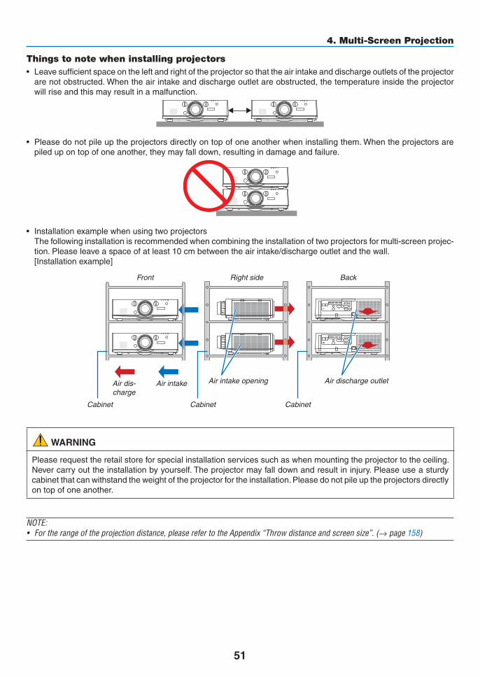
51
4. Multi-Screen Projection
Things to note when installing projectors• Leavesufficientspaceontheleftandrightoftheprojectorsothattheairintakeanddischargeoutletsoftheprojectorarenotobstructed.Whentheairintakeanddischargeoutletareobstructed,thetemperatureinsidetheprojectorwillriseandthismayresultinamalfunction.
• Pleasedonotpileuptheprojectorsdirectlyontopofoneanotherwheninstallingthem.Whentheprojectorsarepiledupontopofoneanother,theymayfalldown,resultingindamageandfailure.
• Installationexamplewhenusingtwoprojectors Thefollowinginstallationisrecommendedwhencombiningtheinstallationoftwoprojectorsformulti-screenprojec-tion.Pleaseleaveaspaceofatleast10cmbetweentheairintake/dischargeoutletandthewall.[Installationexample]
Airintakeopening Airdischargeoutlet
CabinetCabinetCabinet
Airdis-charge
Airintake
Front Rightside Back
WARNING
Pleaserequesttheretailstoreforspecialinstallationservicessuchaswhenmountingtheprojectortotheceiling.Nevercarryouttheinstallationbyyourself.Theprojectormayfalldownandresultininjury.Pleaseuseasturdycabinetthatcanwithstandtheweightoftheprojectorfortheinstallation.Pleasedonotpileuptheprojectorsdirectlyontopofoneanother.
NOTE:• Fortherangeoftheprojectiondistance,pleaserefertotheAppendix“Throwdistanceandscreensize”.(→ page 158)

52
4. Multi-Screen Projection
❷ Displaying Two Pictures at the Same TimeTheprojectorhasafeaturethatallowsyoutoviewtwodifferentsignalssimultaneously.Youhavetwomodes:PIPmodeandPICTUREBYPICTUREmode.Theprojectionvideointhefirstscreendisplayisknownasthemaindisplaywhiletheprojectionvideothatiscalledoutsubsequentlyisknownasthesub-display.Selecttheprojectionfunctionunder[DISPLAY]→[PIP/PICTUREBYPICTURE]→[MODE]intheon-screenmenu(thedefaultfactorysettingwhenshippedisPIP).(→page85)• Asinglescreenisprojectedwhenpoweristurnedon.
Picture in Picture functionAsmallsub-displayisdisplayedinsidethemaindisplay.
Thesub-displaycanbesetupandadjustedasfollows.(→page86)• Selectwhethertodisplaythesub-displayatthetopright,topleft,bottomrightorbottomleftofthescreen(thesizeofthesub-displaycanbeselectedandthepositioncanbefine-tuned)• Switchthemaindisplaywiththesub-display
Main Display
Sub-Display
PicturebypicturefunctionDisplaythemaindisplayandsub-displaysidebyside.
Themaindisplayandsub-displaycanbesetupandadjustedasfollows.(→ page86)• Selectingthedisplayboundary(ratio)ofthemaindisplayandsub-display• Switchthemaindisplayandsub-display
Main Display Sub-Display
Input terminals that can be used for the main screen and sub-screen.Themainscreenandsub-screencanprovidethefollowinginputterminals.• Themaindisplayandsub-displaysupportcomputersignalsuptoWUXGA@60HzRB.
Sub-Display or additional displayHDMI1 HDMI2 DisplayPort BNC BNC(CV) BNC(Y/C) COMPUTER HDBaseT
Main Display
HDMI1No
Yes Yes Yes YesNoHDMI2 Yes Yes Yes Yes
DisplayPort Yes Yes Yes YesBNC Yes Yes Yes
NoNo Yes
BNC(CV) Yes Yes Yes Yes YesBNC(Y/C) Yes Yes Yes Yes YesCOMPUTER Yes Yes Yes No Yes Yes No YesHDBaseT No Yes Yes Yes Yes No
NOTE:• Somesignalsmaynotappeardependingontheresolution.

53
4. Multi-Screen Projection
Projecting two screens1. PresstheMENUbuttontodisplaytheon-screenmenuandselect [DISPLAY]→ [PIP/PICTUREBYPIC-
TURE].
Thisdisplaysthe[PIP/PICTUREBYPICTURE]screenintheon-screenmenu.
2. Select[SUBINPUT]usingthe▼/▲ buttons, and press the ENTER button.
Thisdisplaysthe[SUBINPUT]screen.
3. Select the input signal using the ▼/▲ buttons, and press the ENTER button.
The[PIP](PICTUREINPICTURE)or[PICTUREBYPICTURE]screensetupunder[MODE]isprojected.(→page85)
• Whenthesignalnameisdisplayedingrey,thismeansthatitcannotbeselected.
• ThesignalcanalsobeselectedbypressingthePIPbuttonorPBP/POPbuttonontheremotecontrol.
4. Press the MENU button.
Theon-screenmenuwilldisappear.
5. Whenreturningtosinglescreen,displaythe[PIP/PICTUREBYPICTUE]screenonemoretimeandselect[OFF]inthe[SUBINPUT]screenoftheStep3.
TIP:• Duringdual-screenprojection,iftheselectedinputisnotsupportedbythesub-screen,thesub-screenwillappearasablack
screen.

54
4. Multi-Screen Projection
Switching the main display with the sub-display and vice versa1. PresstheMENUbuttontodisplaytheon-screenmenuandselect [DISPLAY]→ [PIP/PICTUREBYPIC-
TURE].
Thisdisplaysthe[PIP/PICTUREBYPICTURE]screenintheon-screenmenu.
2. Select[PICTURESWAP]usingthe▼/▲ buttons and then press the ENTER button.
Displaythescreenforswitchingthedisplaypositions.
3. Select[ON]usingthe▼ button and then press the ENTER button.
Thevideoofthemaindisplaywillswitchwiththatofthesub-display.
Whenturned“OFF” Whenturned“ON”
Sub-displayvideo
Maindisplayvideo Sub-displayvideo
Maindisplayvideo
ThesignaloutputfromtheHDMIoutputterminaldoesnotchangeevenifthedisplaypositionsareswitched.
4. Press the menu button.
Theon-screenmenuwilldisappear.

55
4. Multi-Screen Projection
Restrictions
• Thefollowingoperationsareenabledonlyforthemaindisplay.
• Audio-visualadjustments
• Videomagnification/compressionusingthepartialD-ZOOM/ZOOM+/−buttons.
However,magnification/compressionisuptothepositionssetin[PICTUREBYPICTUREBORDER]only.
• TESTPATTERN
• Thefollowingoperationsareenabledforboththemaindisplayandsub-display.Theseoperationscannotbeap-pliedindividually.
• Momentarydeletionofvideo/audio
• Videopause
• [PIP/PICTUREBYPICTURE]cannotbeusedwhena3Dvideoisbeingdisplayed.
• Whenusingthe[PIP/PICTUREBYPICTURE]function,[CLOSEDCAPTION]and[DYNAMICCONTRAST]canbeused.
• [PIP/PICTUREBYPICTURE]cannotbeusedwhenthesignalinputhasaresolutionof1920×1200ormore.
• TheHDMIoutputterminalhasarepeaterfunction.Theoutputresolutionislimitedbythemaximumresolutionoftheconnectedmonitorandprojector.

56
4. Multi-Screen Projection
❸ Displaying a Picture Using [EDGE BLENDING]Ahighresolutionvideocanbeprojectedonanevenbiggerscreenbycombiningmultipleprojectorsontheleft,right,topandbottom.Thisprojectorisequippedwithan“EDGEBLENDINGFunction”thatmakestheedges(boundaries)oftheprojectionscreenindistinguishable.
NOTE:• Forprojectorthrowdistances,referto“Throwdistanceandscreensize”onpage158.• BeforeperformingtheEdgeBlendingfunction,placetheprojectorinthecorrectpositionsothattheimagebecomessquarein
the appropriate size, and then make optical adjustments (lens shift, focus, and zoom).• Adjustthebrightnessofeachprojectorusing[LAMPADJUST]under[LAMPMODE].Inaddition,use[REF.WHITEBALANCE]to
adjustthe[CONTRAST],[BRIGHTNESS]and[UNIFORMITY].
Before explaining use of the Edge Blending functionThissectionexplainsthecasefor“Example:Placingtwoprojectorssidebyside”.Asshown,theprojectedimageontheleftisreferredtoas“ProjectorA”andtheprojectedimageontherightisreferredto“ProjectorB”.Unlessotherwisespecifiedhereinafter,the“projector”isusedtomeanbothAandB.
Example:Placingtwoprojectorssidebyside
EdgeBlendingarea
Projectedarea Projectedarea
ProjectorA ProjectorB
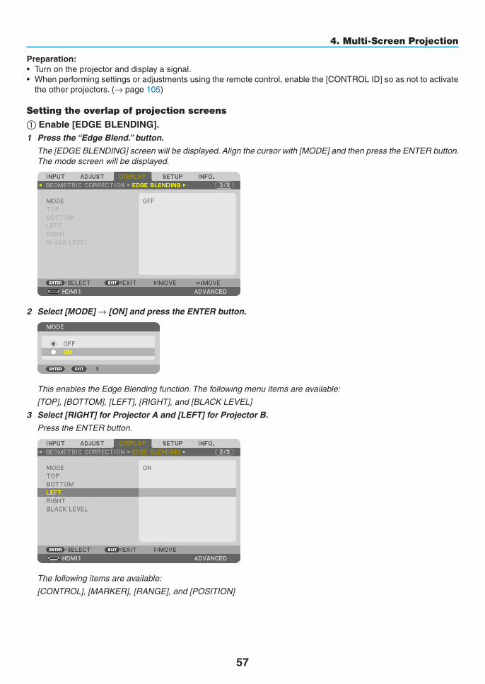
57
4. Multi-Screen Projection
Preparation:• Turnontheprojectoranddisplayasignal.• Whenperformingsettingsoradjustmentsusingtheremotecontrol,enablethe[CONTROLID]soasnottoactivatetheotherprojectors.(→page105)
Setting the overlap of projection screens
① Enable [EDGE BLENDING].1 Press the “Edge Blend.” button.
The[EDGEBLENDING]screenwillbedisplayed.Alignthecursorwith[MODE]andthenpresstheENTERbutton.Themodescreenwillbedisplayed.
2 Select[MODE]→[ON]andpresstheENTERbutton.
ThisenablestheEdgeBlendingfunction.Thefollowingmenuitemsareavailable:
[TOP],[BOTTOM],[LEFT],[RIGHT],and[BLACKLEVEL]
3 Select[RIGHT]forProjectorAand[LEFT]forProjectorB.
PresstheENTERbutton.
Thefollowingitemsareavailable:
[CONTROL],[MARKER],[RANGE],and[POSITION]

58
4. Multi-Screen Projection
4 Select[CONTROL]→[ON]andpresstheENTERbutton.
Each[TOP],[BOTTOM],[LEFT],[RIGHT],and[BLACKLEVEL]hasitsown[CONTROL],[MARKER],[RANGE],and[POSITION].
• ForProjectorA,setthe[CONTROL]forthe[TOP],[LEFT]and[BOTTOM]to[OFF].SimilarlyforProjectorB,setthe[CONTROL]forthe[TOP],[RIGHT]and[BOTTOM]to[OFF].
② Adjust [RANGE] and [POSITION] to determine an area of overlapped edges of images projected from each projector.Turningon[MARKER]willdisplaymarkersinmagentaandgreen.Themagentamarkerisusedfor[RANGE]andgreenonefor[POSITION].
[RANGE](Determineanareaofoverlappededgesofimages.)
[POSITION](Determinethepositionofoverlappededgesofimages.)Greenmarker
Turnon[RIGHT]
Magentamarker
Turnon[LEFT]
Magentamarker
* The2screensareseparatedinthediagramforexplanatorypurposes.

59
4. Multi-Screen Projection
1 Adjust[RANGE].
Usethe◀ or ▶buttontoadjusttheoverlappedarea.
TIP:• Adjusttooverlaponeprojector’markerwiththeotherprojector’smarker.
2 Adjust[POSITION].
Usethe◀ or ▶buttontoalignoneedgewiththeotheredgeofoverlappedimages.
TIP:• Whendisplayingasignalwithadifferentresolution,performtheEdgeBlendingfunctionfromthestart.• Settingof[MARKER]willnotbesavedandreturnto[OFF]whentheprojectoristurnedoff.• Todisplayorhidethemarkerwhiletheprojectorisrunning,turnonoroff[MARKER]fromthemenu.

60
4. Multi-Screen Projection
Black Level AdjustmentThisadjuststheblackleveloftheoverlappingareaandthenon-overlappingareaofthemulti-screen(EDGEBLEND-ING).Adjustthebrightnesslevelifyoufeelthedifferenceistoolarge.
NOTE: Thisfunctionisenabledonlywhen[MODE]isturnedon.Adjustableareavariesdependingonwhatcombinationof[TOP],[BOTTOM],[LEFT]and[RIGHT]areturnedon.
Example:AdjustingtheBlackLevelwhenplacingtwoprojectorssidebyside
Widthofoverlap
Adjust[CENTER] Adjust[CENTER]
ProjectorA’simage
ProjectorB’simage
Adjust[CENTER-RIGHT] Adjust[CENTER-LEFT]
1. Turnon[MODE]
2. Select[BLACKLEVEL]andpresstheENTERbutton.
Thescreenwillswitchtotheblackleveladjustmentscreen.
3. Use the ▼ or ▲ button to select an item and use the ◀ or ▶ to adjust the black level.
Dothisfortheotherprojectorifnecessary.
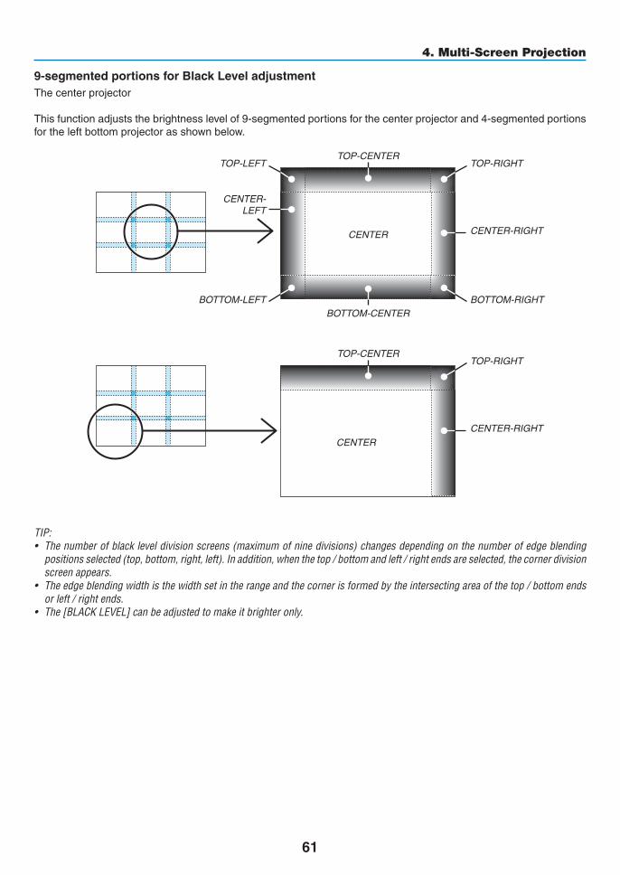
61
4. Multi-Screen Projection
9-segmentedportionsforBlackLeveladjustmentThecenterprojector
Thisfunctionadjuststhebrightnesslevelof9-segmentedportionsforthecenterprojectorand4-segmentedportionsfortheleftbottomprojectorasshownbelow.
TOP-LEFT
BOTTOM-LEFT
CENTER-LEFT
TOP-RIGHT
CENTER-RIGHT
BOTTOM-RIGHT
TOP-CENTER
CENTER
CENTER
BOTTOM-CENTER
TOP-RIGHT
CENTER-RIGHT
TOP-CENTER
TIP:• Thenumberofblackleveldivisionscreens(maximumofninedivisions)changesdependingonthenumberofedgeblending
positions selected (top, bottom, right, left). In addition, when the top / bottom and left / right ends are selected, the corner division screen appears.
• Theedgeblendingwidthisthewidthsetintherangeandthecornerisformedbytheintersectingareaofthetop/bottomendsor left / right ends.
• The[BLACKLEVEL]canbeadjustedtomakeitbrighteronly.
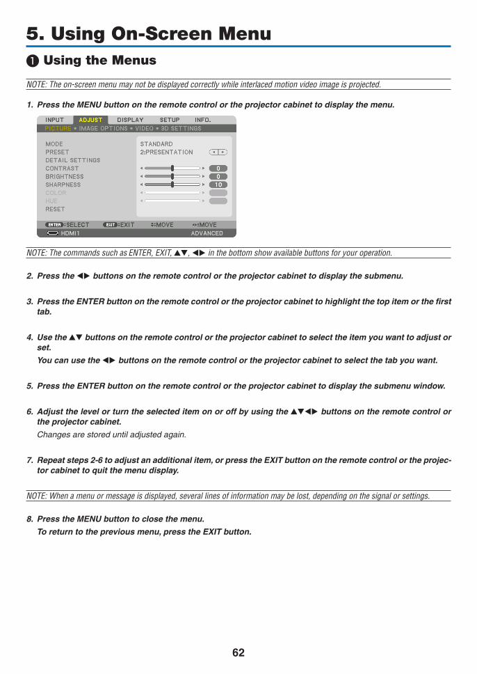
62
5. Using On-Screen Menu❶ Using the Menus
NOTE: The on-screen menu may not be displayed correctly while interlaced motion video image is projected.
1. Press the MENU button on the remote control or the projector cabinet to display the menu.
NOTE: The commands such as ENTER,EXIT,▲▼, ◀▶ in the bottom show available buttons for your operation.
2. Press the ◀▶ buttons on the remote control or the projector cabinet to display the submenu.
3. Press the ENTER button on the remote control or the projector cabinet to highlight the top item or the first tab.
4. Use the ▲▼ buttons on the remote control or the projector cabinet to select the item you want to adjust or set.
You can use the ◀▶ buttons on the remote control or the projector cabinet to select the tab you want.
5. Press the ENTER button on the remote control or the projector cabinet to display the submenu window.
6. Adjust the level or turn the selected item on or off by using the ▲▼◀▶ buttons on the remote control or the projector cabinet.
Changesarestoreduntiladjustedagain.
7. Repeat steps 2-6 to adjust an additional item, or press the EXIT button on the remote control or the projec-tor cabinet to quit the menu display.
NOTE:Whenamenuormessageisdisplayed,severallinesofinformationmaybelost,dependingonthesignalorsettings.
8. Press the MENU button to close the menu.
To return to the previous menu, press the EXIT button.

63
5. Using On-Screen Menu
❷ Menu ElementsSlidebar
Solidtriangle
Menumode
Tab
Radiobutton
HighAltitudesymbol
ECOmodesymbol
Menuwindowsordialogboxestypicallyhavethefollowingelements:
Highlight ����������������������������� Indicates the selected menu or item� Solid triangle ���������������������� Indicates further choices are available� A highlighted triangle indicates the item is active� Tab �������������������������������������� Indicates a group of features in a dialog box� Selecting on any tab brings its page to the front�Radio button �����������������������Use this round button to select an option in a dialog box�Source �������������������������������� Indicates the currently selected source�Menu mode ������������������������ Indicates the current menu mode: BASIC or ADVANCED�Off Timer remaining time ���� Indicates the remaining countdown time when the [OFF TIMER] is preset�Slide bar ����������������������������� Indicates settings or the direction of adjustment�ECO mode symbol �������������� Indicates [ECO MODE] is set�Key Lock symbol ���������������� Indicates the [CONTROL PANEL LOCK] is enabled�Thermometer symbol ��������� Indicates the [ECO MODE] is forcibly set to [ON] mode because the internal temperature is too
high�High Altitude symbol ���������� Indicates the [FAN MODE] is set to [HIGH ALTITUDE] mode�
Source
Availablebuttons
Thermometersymbol
KeyLocksymbol
OffTimerremainingtime
Highlight

64
5. Using On-Screen Menu
* Theasterisk(*)indicatesthatthedefaultsettingvariesdependingonthesignal.*1 The[GAMMACORRECTION]itemisavailablewhenanitemotherthan[DICOMSIM.]isselectedfor[REFERENCE].*2 The[SCREENSIZE]itemisavailablewhen[DICOMSIM.]isselectedfor[REFERENCE].*3 When[PRESENTATION]or[HIGH-BRIGHT]isselectedin[REFERENCE],the[COLORTEMPERATURE]isnotavailable.
•Basicmenuitemsareindicatedbyshadedarea.❸ List of Menu ItemsSomemenuitemsarenotavailabledependingontheinputsource.Menu Item Default Options
INPUT
1:HDMI1 *2:HDMI2 *3:DisplayPort *4:BNC *5:BNC(CV) *6:BNC(Y/C) *7:COMPUTER *8:HDBaseTENTRY LISTTEST PATTERN
ADJUST
PICTURE
MODE STANDARD STANDARD, PROFESSIONAL
PRESET * HIGH-BRIGHT, PRESENTATION, VIDEO, MOVIE, GRAPHIC, sRGB, DICOM SIM�
DETAIL SETTINGS
GENERAL
REFERENCE * HIGH-BRIGHT, PRESENTATION, VIDEO, MOVIE, GRAPHIC, sRGB, DICOM SIM�
GAMMA CORRECTION*1 DYNAMIC, NATURAL, BLACK DETAILSCREEN SIZE*2 * LARGE, MEDIUM, SMALLCOLOR TEMPERATURE*3 *DYNAMIC CONTRAST * OFF, MOTION IMAGE, STILL IMAGE
WHITE BALANCECONTRAST R 0CONTRAST G 0CONTRAST B 0BRIGHTNESS R 0BRIGHTNESS G 0BRIGHTNESS B 0
COLOR CORRECTIONRED 0GREEN 0BLUE 0YELLOW 0MAGENTA 0CYAN 0
CONTRAST 50BRIGHTNESS 50SHARPNESS 10COLOR 50HUE 0RESET
IMAGE OPTIONS
CLOCK *PHASE *HORIZONTAL *VERTICAL *BLANKING * TOP, BOTTOM, LEFT, RIGHTOVERSCAN * AUTO, 0[%], 5[%], 10[%]
ASPECT RATIO
* (COMPUTER) AUTO, 4:3, 5:4, 16:9, 15:9, 16:10, NATIVE
* (COMPONENT/VIDEO/S-VIDEO) AUTO, 4:3, LETTERBOX, WIDE SCREEN, ZOOM
* (COMPONENT/VIDEO/S-VIDEO) AUTO, 4:3 WINDOW, LETTERBOX, WIDE SCREEN, FULL
INPUT RESOLUTION * –
VIDEO
NOISE REDUCTIONRANDOM NR * OFF, LOW, MEDIUM, HIGHMOSQUITO NR OFF OFF, LOW, MEDIUM, HIGHBLOCK NR OFF OFF, LOW
DEINTERLACE NORMAL NORMAL, MOVIE, STILLCONTRAST ENHANCEMENT
MODE AUTO OFF, AUTO, NORMALGAIN
SIGNAL TYPE AUTO AUTO, RGB, COMPONENTVIDEO LEVEL AUTO AUTO, NORMAL, ENHANCED
3D SETTINGS
STEREO VIEWER SINGLE SINGLE, DUAL LEFT, DUAL RIGHTSTEREO FILTER SINGLE SINGLE, DUAL LEFT, DUAL RIGHT
FORMAT AUTOAUTO, OFF(2D), FRAME PACKING, SIDE BY SIDE(HALF), SIDE BY SIDE(FULL), TOP AND BOTTOM, FRAME ALTERNATIVE, LINE ALTERNATIVE
L/R INVERT OFF OFF, ON

65
5. Using On-Screen Menu
Menu Item Default Options
DISPLAY
PIP/PICTURE BY PICTURE
SUB INPUT OFF, HDMI1, HDMI2, DisplayPort, BNC, BNC(CV), BNC(Y/C), COMPUTER, HDBaseT
MODE PIP, PICTURE BY PICTUREPICTURE SWAP OFF OFF, ON
PIP SETTING
START POSITION TOP-LEFT, TOP-RIGHT, BOTTOM-LEFT, BOTTOM-RIGHTHORIZONTAL POSITIONVERTICAL POSITIONSIZE LARGE, MEDIUM, SMALL
BORDER
GEOMETRIC CORRECTION
KEYSTONE
HORIZONTALVERTICALTILTTHROW RATIO
CORNERSTONE TOP-LEFT, TOP, TOP-RIGHT, LEFT, RIGHT, BOTTOM-LEFT, BOTTOM, BOTTOM-RIGHT
HORIZONTAL CORNER TOP-LEFT, TOP, TOP-RIGHT, LEFT, RIGHT, BOTTOM-LEFT, BOTTOM, BOTTOM-RIGHT
VERTICAL CORNER TOP-LEFT, TOP, TOP-RIGHT, LEFT, RIGHT, BOTTOM-LEFT, BOTTOM, BOTTOM-RIGHT
PINCUSHION TOP, BOTTOM, LEFT, RIGHTPC TOOL OFF OFF, 1, 2, 3RESET
EDGE BLENDING
MODE OFF OFF, ON
TOP
CONTROL ON OFF, ONMARKER ON OFF, ONRANGEPOSITION
BOTTOM
CONTROL ON OFF, ONMARKER ON OFF, ONRANGEPOSITION
LEFT
CONTROL ON OFF, ONMARKER ON OFF, ONRANGEPOSITION
RIGHT
CONTROL ON OFF, ONMARKER ON OFF, ONRANGEPOSITION
BLACK LEVEL
TOP-LEFTTOP-CENTERTOP-RIGHTCENTER-LEFTCENTERCENTER-RIGHTBOTTOM-LEFTBOTTOM-CENTERBOTTOM-RIGHT
MULTI SCREEN
WHITE BALANCE
MODE OFF OFF, ONCONTRAST WCONTRAST RCONTRAST GCONTRAST BBRIGHTNESS WBRIGHTNESS RBRIGHTNESS GBRIGHTNESS B
PICTURE SETTING
MODE OFF OFF, ZOOM, TILING
ZOOM
HORIZONTAL ZOOMVERTICAL ZOOMHORIZONTAL POSITIONVERTICAL POSITION
TILING
WIDTH 1 UNIT, 2 UNITS, 3 UNITS, 4 UNITSHEIGHT 1 UNIT, 2 UNITS, 3 UNITS, 4 UNITSHORIZONTAL POSITION 1st UNIT, 2nd UNIT, 3rd UNIT, 4th UNITVERTICAL POSITION 1st UNIT, 2nd UNIT, 3rd UNIT, 4th UNIT

66
5. Using On-Screen Menu
Menu Item Default Options
SETUP
MENU
LANGUAGE ENGLISH
ENGLISH, DEUTSCH, FRANÇAIS, ITALIANO, ESPAÑOL, SVENSKA, 日本語DANSK, PORTUGUÊS, ČEŠTINA, MAGYAR, POLSKI, NEDERLANDS, SUOMINORSK, TÜRKÇE, РУССКИЙ, , Ελληνικά, 中文, 한국어ROMÂNĂ, HRVATSKA, БЪЛГАРСКИ, INDONESIA, हिन्दी, ไทย,
, 繁體中文COLOR SELECT COLOR COLOR, MONOCHROMEINPUT DISPLAY ON OFF, ONMESSAGE DISPLAY ON OFF, ONID DISPLAY ON OFF, ONECO MESSAGE OFF OFF, ON3D CAUTION MESSAGE ON OFF, ON
DISPLAY TIME AUTO 45 SEC MANUAL, AUTO 5 SEC, AUTO 15 SEC, AUTO 45 SEC
FILTER MESSAGE OFF OFF, 100[H], 500[H], 1000[H], 2000[H]
INSTALLATION
ORIENTATION AUTO AUTO, DESKTOP FRONT, CEILING REAR, DESKTOP REAR, CEILING FRONT
SCREEN TYPE FREE FREE, 4:3 SCREEN, 16:9 SCREEN, 16:10 SCREEN
WALL COLOR OFFOFF, WHITEBOARD, BLACKBOARD, BLACKBOARD (GRAY), LIGHT YELLOW, LIGHT GREEN, LIGHT BLUE, SKY BLUE, LIGHT ROSE, PINK
FAN MODE AUTO AUTO, HIGH, HIGH ALTITUDE
LAMP MODE ECO MODE OFF OFF, ONLAMP ADJUST
REF� WHITE BALANCE
CONTRAST RCONTRAST GCONTRAST BBRIGHTNESS RBRIGHTNESS GBRIGHTNESS BUNIFORMITY RUNIFORMITY B
STATIC CONVERGENCE
HORIZONTAL RHORIZONTAL GHORIZONTAL BVERTICAL RVERTICAL GVERTICAL B

67
5. Using On-Screen Menu
Menu Item Default Options
SETUP CONTROL
TOOLS
ADMINISTRA-TOR MODE
MENU MODE ADVANCED ADVANCED, BASICNOT SAVE SETTING VALUES OFF OFF, ONNEW PASSWORDCONFIRM PASSWORD
PROGRAM TIMER
ENABLE OFF OFF, ON
SETTINGS
EDIT
ACTIVE OFF, ON
DAY SUN, MON, TUE, WED, THU, FRI, SAT, MON-FRI, MON-SAT, EVERY DAY
TIMEFUNCTION POWER, INPUT, ECO MODEADVANCED SETTINGSPOWER OFF, ON
INPUT HDMI1, HDMI2, DisplayPort, BNC, BNC(CV), BNC(Y/C), COMPUTER, HDBaseT
ECO MODE OFF, ONREPEAT OFF, ON
DELETEUPDOWNBACK
DATE AND TIME SETTINGS
TIME ZONE SETTIMGS
GMT
-12:00, -11:30, -11:00, -10:30, -10:00, -09:30, -09:00, -08:30, -08:00, -07:30, -07:00, -06:30, -06:00, -05:30, -05:00, -04:30, -04:00, -03:30, -03:00, -02:30, -02:00, -01:30, -01:00, -00:30, 00:00, +00:30, +01:00, +01:30, +02:00, +02:30, +03:00, +03:30, +04:00, +04;30, +05:00, +05:30, +06:00, +06:30, +07:00, +07:30, +08:00, +08:30, +09:00, +09:30, +10:00, +10:30, +11:00, +11:30, +12:00, +12:30, +13:00
DATE AND TIME SETTINGS
DATE MM/DD/YYYYTIME HH:MMINTERNET TIME SERVER OFF, ON
IP ADDRESSUPDATE
SUMMER TIME SETTINGS
ENABLE OFF, ONMON(START) 1, 2, 3, 4, 5, 6, 7, 8, 9, 10, 11, 12
DAY(START)FIRST WEEK, SECOND WEEK, THIRD WEEK, FOURTH WEEK, LAST WEEKSUN, MON, TUE, WED, THU, FRI, SAT
TIME(START)MON(EXIT) 1, 2, 3, 4, 5, 6, 7, 8, 9, 10, 11, 12
DAY(EXIT)FIRST WEEK, SECOND WEEK, THIRD WEEK, FOURTH WEEK, LAST WEEKSUN, MON, TUE, WED, THU, FRI, SAT
TIME(EXIT)TIME DIFFERENCE +01:00, +00:30, -00:30, -01:00
MOUSE (Note) Cannot be used for this device�CONTROL PANEL LOCK OFF OFF, ONSECURITY OFF OFF, ONCOMMUNICATION SPEED 38400bps 4800bps, 9600bps, 19200bps, 38400bps, 115200bps
CONTROL ID CONTROL ID NUMBER 1 1–254CONTROL ID OFF OFF, ON
REMOTE SENSOR FRONT/BACK FRONT/BACK, FRONT, BACK, HDBase-T
BEEP ON OFF, ON

68
5. Using On-Screen Menu
Menu Item Default Options
SETUP
NETWORK SETTINGS
WIRED LAN
PROFILES DISABLE, PROFILE 1, PROFILE 2DHCP OFF, ONIP ADDRESS 192�168�0�10SUBNET MASK 255�255�255�0GATEWAY 192�168�0�1AUTO DNS OFF, ONDNS CONFIGURATIONRECONNECT
PROJECTOR NAME PROJECTOR NAME PA622U Series
DOMAIN HOST NAME necpjDOMAIN NAME
ALERT MAIL
ALERT MAIL OFF, ONHOST NAMEDOMAIN NAMESENDER'S ADDRESSSMTP SERVER NAMERECIPIENT'S ADDRESS 1RECIPIENT'S ADDRESS 2RECIPIENT'S ADDRESS 3TEST MAIL
NETWORK SERVICE
HTTP SERVER
NEW PASSWORDCONFIRM PASSWORD
PJLink NEW PASSWORDCONFIRM PASSWORD
AMX BEACON OFF, ON
SOURCE OPTIONS
AUTO ADJUST NORMAL OFF, NORMAL, FINE
COLOR SYSTEM BNC(VIDEO) AUTO AUTO, NTSC3�58, NTSC4�43, PAL, PAL-M, PAL-N, PAL60, SECAMBNC(Y/C) AUTO AUTO, NTSC3�58, NTSC4�43, PAL, PAL-M, PAL-N, PAL60, SECAM
AUDIO SELECT
HDMI1 HDMI1 HDMI1, BNCHDMI2 HDMI2 HDMI2, BNCDisplayPort DisplayPort DisplayPort, BNCHDBaseT HDBaseT HDBaseT, BNC
DEFAULT INPUT SELECT LAST LAST, AUTO, HDMI1, HDMI2, DisplayPort, BNC, BNC(CV), BNC(Y/C), COMPUTER, HDBaseT
SEAMLESS SWITCHING OFF OFF, ON
CLOSED CAPTION OFF OFF, CAPTION1, CAPTION2, CAPTION3, CAPTION4, TEXT1, TEXT2, TEXT3, TEXT4
BACKGROUND BLUE BLUE, BLACK, LOGO
POWER OPTIONS
STANDBY MODE NORMAL NORMAL, HDBaseT STANDBYDIRECT POWER ON OFF OFF, ONAUTO POWER ON SELECT OFF OFF, HDMI1, HDMI2, DisplayPort, COMPUTER, HDBaseTAUTO POWER OFF 1:00 OFF, 0:05, 0:10, 0:15, 0:20, 0:30, 1:00OFF TIMER OFF OFF, 0:30, 1:00, 2:00, 4:00, 8:00, 12:00, 16:00
RESET
CURRENT SIGNALALL DATAALL DATA (INCLUDING ENTRY LIST)CLEAR LAMP HOURSCLEAR FILTER HOURS

69
5. Using On-Screen Menu
Menu Item Default Options
INFO�
USAGE TIME
LAMP LIFE REMAININGLAMP HOURS USEDFILTER HOURS USEDTOTAL CARBON SAVINGS
SOURCE(1)
INPUT TERMINALRESOLUTIONHORIZONTAL FREQUENCYVERTICAL FREQUENCYSYNC TYPESYNC POLARITYSCAN TYPESOURCE NAMEENTRY NO�
SOURCE(2)
SIGNAL TYPEVIDEO TYPEBIT DEPTHVIDEO LEVELLINK RATELINK LANE3D FORMAT
WIRED LAN
IP ADDRESSSUBNET MASKGATEWAYMAC ADDRESS
VERSION(1)FIRMWAREDATASUB-CPU
OTHERS
DATE TIMEPROJECTOR NAMEMODEL NO�SERIAL NUMBERCONTROL ID (when [CONTROL ID] is set)
CONDITIONS
INTAKE TEMPERATUREEXHAUST TEMPERATUREINSTALLATION POSITIONX-AXISY-AXISZ-AXIS
HDBaseT
SIGNAL QUALITYOPERATION MODELINK STATUSHDMI STATUS

70
5. Using On-Screen Menu
❹ Menu Descriptions & Functions [INPUT]
1:HDMI1ThisprojectsthevideoofthedeviceconnectedtotheHDMI1INterminal.
2:HDMI2ThisprojectsthevideoofthedeviceconnectedtotheHDMI2INterminal.
3:DisplayPortThisprojectsthevideoofthedeviceconnectedtotheDisplayPortinputterminal.
4:BNCThisprojectsthevideoofthedeviceconnectedtothevideoinputterminal.(ThisprojectstheanalogRGBsignalorcomponentsignal.)
5:BNC(CV)ThisprojectsthevideoofthedeviceconnectedtotheBNC(CV)videoinputterminal.(Thisprojectsthecompositevideosignal.)
6:BNC(Y/C)ThisprojectsthevideoofthedeviceconnectedtotheBNC(Y/C)videoinputterminal.(ThisprojectstheS-videosignal.)
7:COMPUTERThisprojectsthevideoofthedeviceconnectedtothecomputervideoinputterminal.(ThisprojectstheanalogRGBsignalorcomponentsignal.)
8:HDBaseTProjectingtheHDBaseTorWIREDLANsignal.
ENTRY LISTDisplaysalistofsignals.Seethefollowingpages.
TEST PATTERNClosesthemenuandswitchestothetestpatternscreen.

71
5. Using On-Screen Menu
UsingtheEntryListWhenanysourceadjustmentsaremade,theadjustmentsareautomaticallyregisteredintheEntryList.The(adjust-mentvaluesof)registeredsignalscanbeloadedfromtheEntryListwhenevernecessary.However,onlyupto100patternscanberegisteredintheEntryList.When100patternshavebeenregisteredintheEntryList,anerrormessageisthendisplayedandnoadditionalpatternscanberegistered.Youshouldthusdelete(adjustmentvaluesof)signalsthatarenolongerneeded.
DisplayingtheEntrylist1. Press the MENU button.
Themenuwillbedisplayed.
2. Press the ◀ or ▶buttontoselect[INPUT].
TheINPUTlistwillbedisplayed.
3. Use the ◀, ▶, ▲, or ▼toselect[ENTRYLIST]andpresstheENTERbutton.
TheENTRYLISTwindowswillbedisplayed.
IftheENTRYLISTwindowisnotdisplayed,switchthemenuto[ADVANCED].
Toswitchthemenubetween[ADVANCED]and[BASIC],select[SETUP]→[CONTROL]→[TOOLS]→[ADMIN-ISTRATORMODE]→[MENUMODE].(→page99)

72
5. Using On-Screen Menu
EnteringthecurrentlyprojectedsignalintotheEntryList[STORE]
1. Press the ▲ or ▼ button to select any number.
2. Press the ◀ or ▶buttontoselect[STORE]andpresstheENTERbutton.
CallingupasignalfromtheEntryList[LOAD]Pressthe▲ or ▼buttontoselectasignalandpresstheENTERbutton.
EditingasignalfromtheEntryList[EDIT]
1. Press the ▲ or ▼ button to select a signal you wish to edit.
2. Press the ◀, ▶, ▲, or ▼buttontoselect[EDIT]andpresstheENTERbutton.
TheEditwindowwillbedisplayed.
SOURCENAME Enterasignalname.Upto18alphanumericcharacterscanbeused.INPUT Theinputterminalcanbechanged.SwitchingbetweenHDMI1/HDMI2/DisplayPort/BNC/
BNC(CV)/BNC(Y/C)/Computerispossible.LOCK Setso that theselectedsignalcannotbedeletedwhen [ALLDELETE] isexecuted.The
changesmadeafterLOCKexecutioncannotbesaved.SKIP Setsothattheselectedsignalwillbeskippedduringautosearch.
3. Settheaboveitemsandselect[OK]andpresstheENTERbutton.
NOTE: The input terminal cannot be changed to the currently projected signal.

73
5. Using On-Screen Menu
CuttingasignalfromtheEntryList[CUT]
1. Press the ▲ or ▼ button to select a signal you wish to delete.
2. Press the ◀, ▶, ▲, or ▼buttontoselect[CUT]andpresstheENTERbutton.
ThesignalwillbedeletedfromtheEntryListandthedeletedsignalwillbedisplayedontheclipboardatthebottomoftheEntryList.
NOTE:• Thecurrentlyprojectedsignalcannotbedeleted.• Whenthelockedsignalisselected,itwillbedisplayedingraywhichindicatesitisnotavailable.
TIP:• DataontheclipboardcanbepassedontotheEntryList.• DataontheclipboardwillnotbelostaftertheEntryListisclosed.
CopyingandpastingasignalfromtheEntryList[COPY]/[PASTE]
1. Press the ▲ or ▼ button to select a signal you wish to copy.
2. Press the ◀, ▶, ▲, or ▼buttontoselect[COPY]andpresstheENTERbutton.
ThecopiedsignalwillbedisplayedontheclipboardatthebottomoftheEntryList.
3. Press the ◀ or ▶ button to move to the list.
4. Press the ▲ or ▼ button to select a signal.
5. Press the ◀, ▶, ▲, or ▼buttontoselect[PASTE]andpresstheENTERbutton.
Dataontheclipboardwillbepastedtothesignal.
DeletingallthesignalsfromtheEntryList[ALLDELTE]
1. Press the ◀, ▶, ▲, or ▼buttontoselect[ALLDELETE]andpresstheENTERbutton.
Theconfirmationmessagewillbedisplayed.
2. Press the ◀ or ▶buttontoselect[YES]andpresstheENTERbutton.
NOTE: The locked signal cannot be deleted.

74
5. Using On-Screen Menu
❺ Menu Descriptions & Functions [ADJUST][PICTURE]
[MODE]Thisfunctionallowsyoutodeterminehowtosavesettingsfor[DETAILSETTINGS]of[PRESET]foreachinput.
STANDARD ������������ Saves settings for each item of [PRESET] (Preset 1 through 7)PROFESSIONAL ����� Saves all the settings of [PICTURE] for each input�
NOTE: • When[TESTPATTERN]isdisplayed,[MODE]cannotbeselected.
[PRESET]Thisfunctionallowsyoutoselectoptimizedsettingsforyourprojectedimage.Youcanadjustneutraltintforyellow,cyanormagenta.Therearesevenfactorypresetsoptimizedforvarioustypesofimages.Youcanalsouse[DETAILSETTINGS]tosetuseradjustablesettingstocustomizeeachgammaorcolor.Yoursettingscanbestoredin[PRESET1]to[PRESET7].
HIGH-BRIGHT �������� Recommended for use in a brightly lit room�PRESENTATION ����� Recommended for making a presentation using a PowerPoint file�VIDEO �������������������� Recommended for typical TV program viewing�MOVIE ������������������� Recommended for movies�GRAPHIC ��������������� Recommended for graphics�sRGB ��������������������� Standard color valuesDICOM SIM� ���������� Recommended for DICOM simulation format�
NOTE: • The[DICOMSIM.]optionisfortraining/referenceonlyandshouldnotbeusedforactualdiagnosis.• DICOMstandsforDigitalImagingandCommunicationsinMedicine.ItisastandarddevelopedbytheAmericanCollegeofRadiol-
ogy(ACR)andtheNationalElectricalManufacturersAssociation(NEMA). Thestandardspecifieshowdigitalimagedatacanbemovedfromsystemtosystem.

75
5. Using On-Screen Menu
[DETAIL SETTINGS]
[GENERAL]Storing Your Customized Settings [REFERENCE]Thisfunctionallowsyoutostoreyourcustomizedsettingsin[PRESET1]to[PRESET7].First,selectabasepresetmodefrom[REFERENCE],thenset[GAMMACORRECTION]and[COLORTEMPERA-TURE].
HIGH-BRIGHT �������� Recommended for use in a brightly lit room�PRESENTATION ����� Recommended for making a presentation using a PowerPoint file�VIDEO �������������������� Recommended for typical TV program viewing�MOVIE ������������������� Recommended for movies�GRAPHIC ��������������� Recommended for graphics�sRGB ��������������������� Standard color values�DICOM SIM� ���������� Recommended for DICOM simulation format�
Selecting Gamma Correction Mode [GAMMA CORRECTION]Eachmodeisrecommendedfor:
DYNAMIC �������������� Creates a high-contrast picture�NATURAL ��������������� Natural reproduction of the picture�BLACK DETAIL ������� Emphasizes detail in dark areas of the picture�
NOTE:Thisfunctionisnotavailablewhen[DICOMSIM.]isselectedfor[DETAILSETTINGS].
Selecting Screen Size for DICOM SIM [SCREEN SIZE]Thisfunctionwillperformgammacorrectionappropriateforthescreensize.
LARGE ������������������� For screen size of 150"MEDIUM ���������������� For screen size of 100"SMALL ������������������� For screen size of 50"
NOTE:Thisfunctionisavailableonlywhen[DICOMSIM.]isselectedfor[DETAILSETTINGS].

76
5. Using On-Screen Menu
Adjusting Color Temperature [COLOR TEMPERATURE]Thisoptionallowsyoutoselectthecolortemperatureofyourchoice.Avaluebetween5000Kand10500Kcanbesetin100Kunits.
NOTE:When[PRESENTATION]or[HIGH-BRIGHT]isselectedin[REFERENCE],thisfunctionisnotavailable.
Adjusting Brightness and Contrast [DYNAMIC CONTRAST]Whenset,themostoptimalcontrastratioisadjustedaccordingtothevideo.
OFF ������������������������ Dynamic contrast is disabled�MOTION IMAGE ����� Most optimal settings for moving images�STILL IMAGE ��������� Most optimal settings for static images� Rapidly follows any changes in the video�
NOTE:• Dependingontheconditions,projectorsettingssuchas[DYNAMICCONTRAST]maynotbeabletobeselected.
Adjusting White Balance [WHITE BALANCE]Thisallowsyoutoadjustthewhitebalance.Contrastforeachcolor(RGB)toadjustthewhitelevelofthescreen;Brightnessforeachcolor(RGB)isusedtoadjusttheblacklevelofthescreen.
[COLOR CORRECTION]Correctsthecolorforallsignals.Adjuststhetoneforthecolorsred,green,blue,yellow,magentaandcyan.
RED HUE +Direction Magentadirection−Direction Yellowdirection
SATURATION +Direction Vivid−Direction Weak
GREEN HUE +Direction Yellowdirection−Direction Cyandirection
SATURATION +Direction Vivid−Direction Weak
BLUE HUE +Direction Cyandirection−Direction Magentadirection
SATURATION +Direction Vivid−Direction Weak
YELLOW HUE +Direction Reddirection−Direction Greendirection
SATURATION +Direction Vivid−Direction Weak
MAGENTA HUE +Direction Bluedirection−Direction Reddirection
SATURATION +Direction Vivid−Direction Weak
CYAN HUE +Direction Greendirection−Direction Bluedirection
SATURATION +Direction Vivid−Direction Weak
[CONTRAST]Adjuststheintensityoftheimageaccordingtotheincomingsignal.
[BRIGHTNESS]Adjuststhebrightnesslevelorthebackrasterintensity.
[SHARPNESS]Controlsthedetailoftheimage.

77
5. Using On-Screen Menu
[COLOR]Increasesordecreasesthecolorsaturationlevel.
[HUE]Variesthecolorlevelfrom+/−greento+/−blue.Theredlevelisusedasreference.
Inputsignal CONTRAST BRIGHTNESS SHARPNESS COLOR HUE
RGBsystemof“COMPUTER/Display-Port/HDMI/HDBaseT”
Yes Yes Yes No No
COMPONENTsystemof“COMPUTER/DisplayPort/HDMI/HDBaseT”
Yes Yes Yes Yes Yes
CompositeVideo/S-Video Yes Yes Yes Yes Yes
Yes=Adjustable,No=Notadjustable
NOTE:• When[TESTPATTERN]isdisplayed,[CONTRAST],[BRIGHTNESS],[SHARPNESS],[COLOR]and[HUE]cannotbeadjusted.
[RESET]Thesettingsandadjustmentsfor[PICTURE]willbereturnedtothefactorysettingswiththeexceptionofthefollowing;Presetnumbersand[REFERENCE]withinthe[PRESET]screen.Thesettingsandadjustmentsunder[DETAILSETTINGS]withinthe[PRESET]screenthatarenotcurrentlyselectedwillnotbereset.

78
5. Using On-Screen Menu
[IMAGE OPTIONS]
AdjustingClockandPhase[CLOCK/PHASE]ThisallowsyoutomanuallyadjustCLOCKandPHASE.
CLOCK ������������������� Use this item to fine tune the computer image or to remove any vertical banding that might appear� This function adjusts the clock frequencies that eliminate the horizontal banding in the image�This adjustment may be necessary when you connect your computer for the first time�
PHASE ������������������� Use this item to adjust the clock phase or to reduce video noise, dot interference or cross talk� (This is evident when part of your image appears to be shimmering�)Use [PHASE] only after the [CLOCK] is complete�
NOTE:The[CLOCK]and[PHASE]itemsareavailableforRGBsignalsonly.
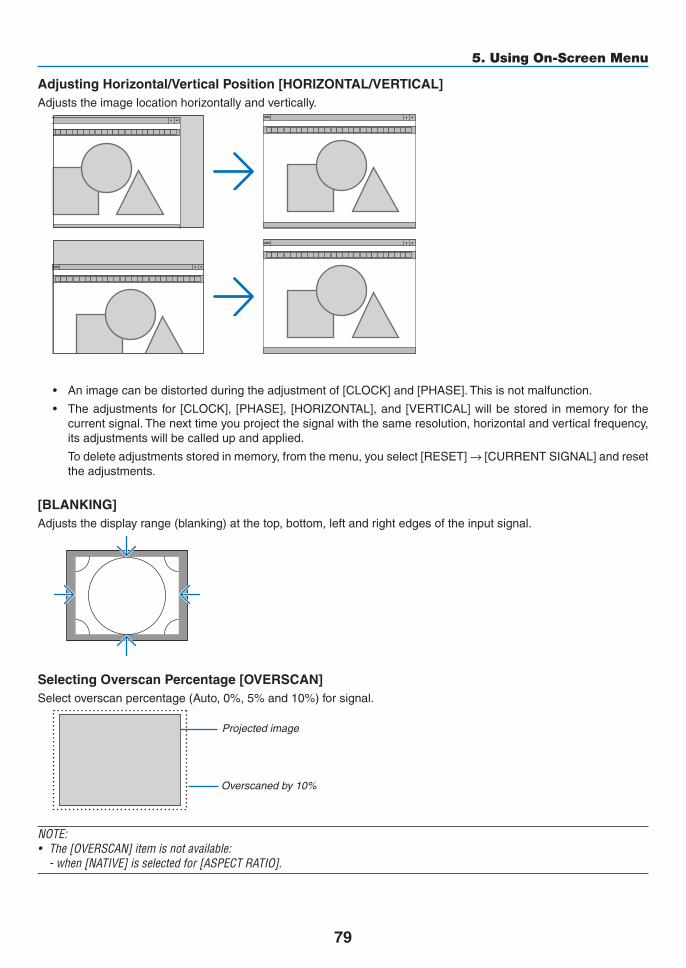
79
5. Using On-Screen Menu
AdjustingHorizontal/VerticalPosition[HORIZONTAL/VERTICAL]Adjuststheimagelocationhorizontallyandvertically.
• Animagecanbedistortedduringtheadjustmentof[CLOCK]and[PHASE].Thisisnotmalfunction.
• Theadjustments for [CLOCK], [PHASE], [HORIZONTAL],and[VERTICAL]willbestored inmemoryfor thecurrentsignal.Thenexttimeyouprojectthesignalwiththesameresolution,horizontalandverticalfrequency,itsadjustmentswillbecalledupandapplied.
Todeleteadjustmentsstoredinmemory,fromthemenu,youselect[RESET]→[CURRENTSIGNAL]andresettheadjustments.
[BLANKING]Adjuststhedisplayrange(blanking)atthetop,bottom,leftandrightedgesoftheinputsignal.
SelectingOverscanPercentage[OVERSCAN]Selectoverscanpercentage(Auto,0%,5%and10%)forsignal.
Projectedimage
Overscanedby10%
NOTE: • The[OVERSCAN]itemisnotavailable: -when[NATIVE]isselectedfor[ASPECTRATIO].

80
5. Using On-Screen Menu
Selecting the Aspect Ratio [ASPECT RATIO]Usethisfunctiontoselectthescreen’svertical:horizontalaspectratio.Selectthescreentype(4:3screen,16:9screenor16:10screen)atthescreensettingbeforesettingtheaspectratio.(→page97)Theprojectorautomaticallyidentifiesthesignalbeinginputandsetstheoptimumaspectratio.
For Computer signal
ForComponent/Video/S-Videosignals
Whenthescreentypeissetto4:3 Whenthescreentypeissetto16:9or16:10
Resolution AspectRatioVGA 640×480 4:3SVGA 800×600 4:3XGA 1024×768 4:3WXGA 1280×768 15:9WXGA 1280×800 16:10HD(FWXGA) 1366×768 approx.16:9WXGA+ 1440×900 16:10SXGA 1280×1024 5:4SXGA+ 1400×1050 4:3WXGA++ 1600×900 16:9UXGA 1600×1200 4:3WSXGA+ 1680×1050 16:10FHD(1080P) 1920×1080 16:9WUXGA 1920×1200 16:10WQXGA 2560×1600 16:10
Options Function
AUTO Theprojectorwillautomaticallydeterminetheincomingsignalanddisplayitinitsaspectratio.Theprojectormayerroneouslydeterminetheaspectratiodependingonitssignal.Ifthisoccurs,selecttheappropriateaspectratiofromthefollowing.
4:3 Theimageisdisplayedin4:3aspectratio.
5:4 Theimageisdisplayedin5:4aspectratio
16:9 Theimageisdisplayedin16:9aspectratio
15:9 Theimageisdisplayedin15:9aspectratio
16:10 Theimageisdisplayedin16:10aspectratio

81
5. Using On-Screen Menu
Options Function
NATIVE Theprojectordisplaysthecurrentimageinitstrueresolutionwhentheincomingcomputersignalhasalowerorhigherresolutionthantheprojector’snativeresolution.(→page2)Whentheincomingcomputersignalhasahigherresolutionthantheprojector'snativeresolution,thecenterofanimagewillbedisplayed.
LETTERBOX Theimageofaletterboxsignal(16:9)isstretchedequallyinthehorizontalandverticaldirectionstofitthescreen.
WIDESCREEN Theimageofasqueezesignal(16:9)isstretchedleftandrightin16:9.
ZOOM Theimageofasqueezesignal(16:9)isstretchedleftandrightin4:3.Partsofthedisplayedimagearecroppedattheleftandrightedgesandthereforenotvisible.
FULL Projecttofullscreensize.
TIP:• Imagepositioncanbeadjustedverticallyusing[POSITION]whenthe[16:9],[15:9],or[16:10]aspectratiosareselected.• Theterm“letterbox”referstoamorelandscape-orientedimagewhencomparedtoa4:3image,whichisthestandardaspect
ratio for a vide source. Theletterboxsignalhasaspectratioswiththevistasize“1.85:1”orcinemascopesize“2.35:1”formoviefilm.• Theterm“squeeze”referstothecompressedimageofwhichaspectratioisconvertedfrom16:9to4:3.
[INPUT RESOLUTION]TheresolutionisassignedautomaticallywhentheresolutionoftheinputsignalfromthecomputervideoinputterminalorBNCvideoinputterminal(analogRGB)cannotbedistinguished.

82
5. Using On-Screen Menu
[VIDEO]
Using Noise Reduction [NOISE REDUCTION]Whenprojectingavideoimage,youcanusethe[NOISEREDUCTION]functiontoreducethescreennoise(roughnessanddistortion).Thisdeviceisequippedwiththreetypesofnoisereductionfunctions.Selectthefunctionaccordingtothetypeofnoise.Dependingonthenoiselevel,thenoisereductioneffectcanbesetto[OFF],[LOW],[MEDIUM]or[HIGH].[NOISEREDUCTION]canbeselectedforSDTV,HDTVsignalandcomponentsignalinput.
RANDOM NR ��������� Reduces flickering random noise in an image� MOSQUITO NR ������ Reduces mosquito noise that appears around the edges of an image during Blu-ray playback�BLOCK NR ������������� Reduces block noise or mosaic-like patterns by selecting ON�
Selecting Interlaced Progressive Conversion Process Mode [DEINTERLACE]Thisfunctionallowsyoutoselectaninterlaced-to-progressiveconversionprocessforvideosignals.
NORMAL ���������������� Automatically distinguishes a moving image from a static image to create a distinct image� Please select [MOVIE] if there are any obvious jitter and noises�
MOVIE ������������������� Select when projecting moving images� This is suitable for signals with a lot of jitter and noise�STILL ��������������������� Select when projecting static images� The video will flicker when a moving image is projected�
NOTE:ThisfunctionisnotavailablewithRGBsignals.
[CONTRAST ENHANCEMENT]Usingthecharacteristicsofthehumaneye,apicturequalitywithasenseofcontrastandresolutionisachieved.
OFF ������������������������ Suite vision is switched off�AUTO ��������������������� Contrast and picture quality are automatically improved using the suite vision function�NORMAL ���������������� Adjust the gain manually�

83
5. Using On-Screen Menu
[SIGNAL TYPE]SelectionofRGBandcomponentsignals.Normally,thisissetto[AUTO].Pleasechangethesettingifthecoloroftheimageremainsunnatural.
AUTO ��������������������� Automatically distinguishes RGB and component signals�RGB ����������������������� Switches to the RGB input�COMPONENT ��������� Switches to the component signal input�
[VIDEOLEVEL]SelectionofthevideosignallevelwhenconnectinganexternaldevicetotheHDMI1INterminal,HDMI2INterminal,DisplayPortinputterminal,andHDBaseTinputterminaloftheprojector.
AUTO ��������������������� The video level is switched automatically based on the information from the device outputting the signal�Depending on the connected device, this setting may not be made properly� In this case, switch to [NORMAL” or “ENHANCED” from the menu and view with the optimum setting�
NORMAL ���������������� This disables the enhanced mode�ENHANCED ������������ This improves the image’s contrast, expressing the dark and light sections more dynamically�SUPER WHITE ������� The video contrast is improved and the dark areas appear more dynamic�

84
5. Using On-Screen Menu
[3D SETTINGS]
Pleasereferto“3-8Projecting3Dvideos”(→page39)fortheoperation.
STEREOVIEWERStackupasingleormultipleprojectorsandcarryoutthesettingsforprojecting3Dvideos.Selecttheleft/rightset-tingsofthe3Deyewearusingthestereoviewer.
SINGLE ������������������ Use a single projector to project 3D videos�DUAL LEFT ������������ Use a dedicated projector for displaying videos on the left�DUAL RIGHT ���������� Use a dedicated projector for displaying videos on the right�
STEREO FILTERStackupasingleormultipleprojectorsandcarryoutthesettingsforprojecting3Dvideos.Imagesettingfor3DglassesmadebyInfitec.
SINGLE ������������������ Use a single projector to project 3D videos�DUAL LEFT ������������ Use a dedicated projector for displaying videos on the left�DUAL RIGHT ���������� Use a dedicated projector for displaying videos on the right�
FORMATSelectthe3Dvideoformat(recording/transmissionformat).Selecttomatchthe3Dbroadcastand3Dmedia.Nor-mally,[AUTO]isselected.Pleaseselectthe3Dinputsignalformatwhenthe3Ddetectionsignaloftheformatcannotbedistinguished.
L/RINVERTInvertthedisplayorderoftheleftandrightvideos.Select[ON]ifyoufeeluncomfortablewiththe3Ddisplaywhen[OFF]isselected.

85
5. Using On-Screen Menu
❻ Menu Descriptions & Functions [DISPLAY][PIP/PICTURE BY PICTURE]
SUB INPUTSelecttheinputsignaltobedisplayedinthesub-display.Pleasereferto“4-2DisplayingTwoPicturesattheSameTime”(→page52)fordetailsontheoperation.
MODESelecteitherPIPorPICTUREBYPICTUREwhenswitchingto2-screendisplay.
PICTURE SWAPThevideosinthemaindisplayandsub-displaywillbeswitched.Pleasereferto“4-2DisplayingTwoPicturesattheSameTime”(→page54)fordetails.
PIP SETTINGSelectthedisplayposition,positionadjustmentandsizeofthesub-displayinthePIPscreen.
START POSITION ��� Selection of the display position of the sub-display when switching to the PIP screen�HORIZONTAL POSITION ������������������������������ Adjust the display position of the sub-display in the horizontal direction� The respective corners will serve
as reference points�VERTICAL POSITION ������������������������������ Adjust the display position of the sub-display in the vertical direction� The respective corners will serve as
reference points�SIZE ����������������������� Select the display size of the sub-display�

86
5. Using On-Screen Menu
TIP:Thehorizontalpositionandverticalpositionaretheamountofmovementfromthereferencepoints.Forexample,whenTOP-LEFTis adjusted, the position is displayed with the same amount of movement even if displayed with other starting positions.The maximum amount of movement is half the resolution of the projector.
ReferencepointAdjustusingthehorizon-talposition
Sub-display Maindisplay
Referencepoint
Adjustusingtheverticalposition
TOP-LEFT TOP-RIGHT
BOTTOM-LEFT BOTTOM-RIGHT
ReferencepointReferencepoint
BORDERSelectthedisplayboundaryofthemaindisplayandsub-displayofthe[PICTUREBYPICTURE]screen.
Displayboundary
Maindisplay Sub-displayMaindisplay Sub-display MaindisplaySub-display
TIP:• ForPA622U/PA522U,sixstagescanbeselected.• ForPA672W/PA572W/PA722X/PA622X,threestagescanbeselected.

87
5. Using On-Screen Menu
[GEOMETRIC CORRECTION]
KEYSTONEDisplaythetrapezoidcorrectionscreenandadjustthetrapezoidaldistortionoftheprojectionscreen.Todisplaythe[KEYSTONE]screen,select→[DISPLAY]→[GEOMETRICCORRECTION]→[KEYSTONE]intheon-screenmenu.The[GEOMETRICCORRECTION]screencanalsobedisplayedbypressingtheGeometric.buttonontheremotecontrol.
HORIZONTAL ��������� Adjustments when projecting from a diagonal direction to the screen�
VERTICAL �������������� Adjustments when projecting from the top or bottom direction to the screen�
TILT ����������������������� Adjusts the distortion when performing trapezoidal correction with the screen moved in the vertical direction using the lens shift�
THROW RATIO ������� Adjusts according to the projection ratio of the optional lens used�
Modelnameoflensunit
Adjustmentrange
NP11FL 8NP30ZL 8–10NP12ZL 12–15NP13ZL 15–30NP14ZL 29–47NP15ZL 46–71
NOTE:• Whenpowerissuppliedtothedevice,theadjustmentvalueofthe[KEYSTONE]usedpreviouslyisretainedevenifthegradient
of the device is changed.• Whenclearingtheadjustmentvalueof[KEYSTONE],presstheGeometric.buttonfor2ormoreseconds.• Whensettingother[GEOMETRICCORRECTION]functions,the[KEYSTONE]menucannotbeselected.Whenperformingtrapezoidal
correction,presstheGeometric.buttonfor2ormoresecondstocleartheadjustmentvalueof[GEOMETRICCORRECTION].• Aselectricalcorrection iscarriedoutby [KEYSTONE], thebrightnessmaybe reducedor thescreenqualitymaydeteriorate
sometimes.

88
5. Using On-Screen Menu
CORNERSTONEDisplaythe4-pointcorrectionscreenandadjustthetrapezoidaldistortionoftheprojectionscreen.Pleasereferto“CorrectingHorizontalandVerticalKeystoneDistortion[CORNERSTONE]”(→page33)fordetailsontheoperation.
HORIZONTALCORNER/VERTICALCORNERDistortioncorrectionforcornerprojectionsuchaswallsurfaces.
HORIZONTAL CORNER ������������������������������ Performs correction for projection onto a wall lying at an angle to the horizontal direction�
* Reverse angle correction is also possible�VERTICAL CORNER ������������������������������ Performs correction for projection onto a wall lying at an angle to the vertical direction�
* Reverse angle correction is also possible�
NOTE:• Whenthemaximumadjustmentrangeisexceeded,distortionadjustmentisdisabled.Setuptheprojectoratanoptimalangleas
the deterioration in the image quality increases as the distortion adjustment volume gets larger.• Pleasenotethattheimagewillgooutoffocusduetothedifferenceinthedistancebetweentheupperandlowerorleftandright
sidesandthecenterofthescreenforprojectionscuttingacrosscorners.Lenseswithshortfocalpointsarealsonotrecommendedfor projections cutting across corners as the image will go out of focus.

89
5. Using On-Screen Menu
Adjustment method1. Alignthecursorwiththe[HORIZONTALCORNER]or[VERTICALCORNER]ofthe[GEOMETRICCORREC-
TION]menuandthenpresstheENTERbutton.
• Theadjustmentscreenwillbedisplayed.
2. Press the ▼▲◀▶ buttons to align the cursor (yellow box) with the target adjustment point and then press the ENTER button.
• Thecursorwillchangeintoanadjustmentpoint(yellowincolor).
3. Press the ▼▲◀▶ buttons to adjust the corners or sides of the screen and then press the ENTER button.
• Theadjustmentpointwillgobacktobeingacursor(yellowbox).
Explanationofscreentransition
• Theadjustmentpointsofthefourcorners(a,c,fandhinthedrawing)willmoveindependently.
• Thefollowingadjustmentpointsdifferatthe[HORIZONTALCORNER]and[VERTICALCORNER].
HORIZONTALCORNER:WhenPointbinthedrawingismoved,andtheuppersideandPointgaremoved,thelowersidewillmoveinaparallelmanner.
VERTICALCORNER:WhenPointdinthedrawingismoved,andtheleftsideandPointearemoved,therightsidewillmoveinaparallelmanner.
[Adjustmentpointsofthe[HORIZONTALCORNER]screenandmovementpointsoftheprojectionscreen]
a
b
b c
d e
f g h
a c
d e
fg
h
PointbwillbedisplacedinaparallelmanneratthesametimeasPointsa,b,c
PointgwillbedisplacedinaparallelmanneratthesametimeasPointsf,g,h
[Adjustmentpointsofthe[VERTICALCORNER]screenandmovementpointsoftheprojectionscreen]
a
a
b
bc
cd
dee
f
f
g
gh
h
PointdwillbedisplacedinaparallelmanneratthesametimeasPointsa,d,f
PointewillbedisplacedinaparallelmanneratthesametimeasPointsf,g,h
4. Start from Step 2 onwards to adjust the other points.
5. When the adjustment is completed, press the ▼▲◀▶buttonstoalignthecursorwiththe[EXIT]intheadjustment screen and then press theENTER button.
• Switchtothe[GEOMETRICCORRECTION]menuscreen.

90
5. Using On-Screen Menu
PINCUSHIONAdjustthecurvedistortionoftheprojectionscreen.
TOP ������������������������ Adjust the curve distortion of the upper edge of the projection screen�
BOTTOM ���������������� Adjust the curve distortion of the lower edge of the projection screen�
LEFT ���������������������� Adjust the curve distortion of the left edge of the projection screen�
RIGHT �������������������� Adjust the curve distortion of the right edge of the projection screen�
TOP
LEFT RIGHT
BOTTOM
PC TOOLRecallthegeometriccorrectiondatathatisregisteredintheprojectorbeforehand.Therearethreetypesofregistereddata.
NOTE:• KEYSTONE,CORNERSTONE,andPINCUSHIONcannotbeselectedwhensettingthegeometriccorrectionusingaPCtool.• Toclearthe[GEOMETRICCORRECTION]datathathasbeensetup,presstheGeometric.buttonfor2ormoreseconds.• Aselectricalcorrectioniscarriedout ingeometriccorrection,thebrightnessmaybeaffectedandthepicturequalitymaybe
degraded.
RESETResettheadjustmentvaluethathasbeensetupinGEOMETRICCORRECTION(returntotheinitialvalue).

91
5. Using On-Screen Menu
[EDGE BLENDING]
Thisadjuststheedges(boundaries)oftheprojectionscreenwhenprojectinghighresolutionvideosusingacombina-tionofseveralprojectorsintheup,down,leftandrightpositions.
MODEThisenablesordisablestheEDGEBLENDINGfunction.WhenMODEissettoON,theTOP,BOTTOM,LEFT,RIGHTandBLACKLEVELsettingscanbeadjusted.
TOP/BOTTOM/LEFT/RIGHTThisselectstheEDGEBLENDINGlocationsontheleft,right,topandbottomonthescreen.Thefollowingsettingscanbeadjustedwhenanitemisselected.(→page57)
CONTROL �������������� Enable TOP, BOTTOM, LEFT and RIGHT functions�MARKER ���������������� Set whether to display marker or not when adjusting the range and display position� When turned on, a
magenta marker for adjusting the range adjustment and a green marker for adjusting the display position will be displayed�
RANGE ������������������� Adjust the range (width) of the edge blending�POSITION �������������� Adjust the display position of the edge blending�
BLACKLEVELDividethescreenintoninepartsandkeeptheblackleveluniformforeachprojector.TheninedivisionsscreensareTOP-LEFT,TOP-CENTER,TOP-RIGHT,CENTER-LEFT,CENTER,CENTER-RIGHT,BOTTOM-LEFT,BOTTOM-CENTERandBOTTOM-RIGHT.(→page60)
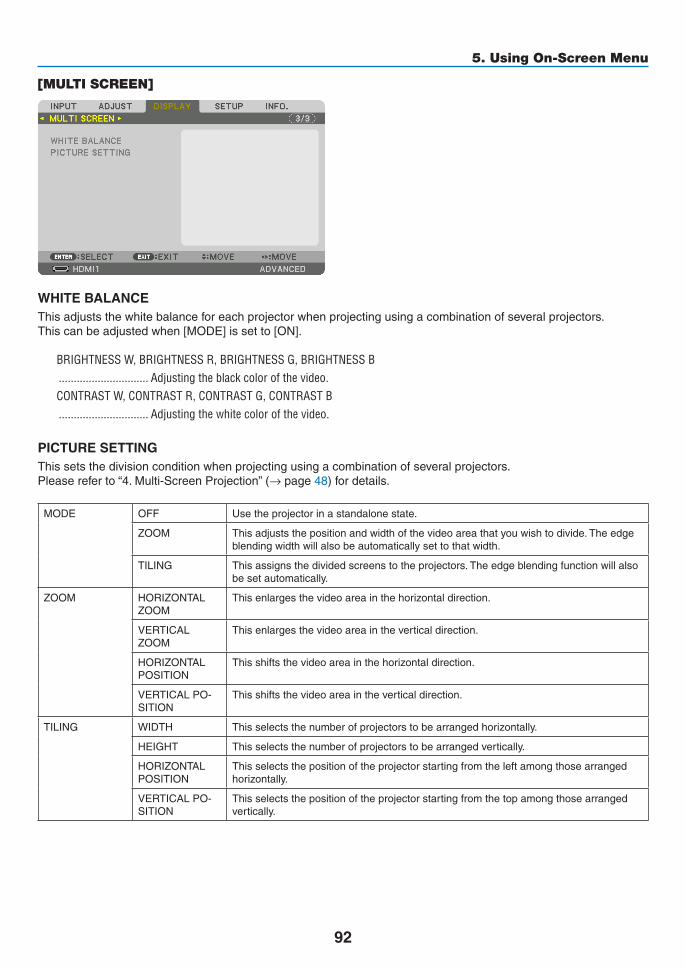
92
5. Using On-Screen Menu
[MULTI SCREEN]
WHITE BALANCEThisadjuststhewhitebalanceforeachprojectorwhenprojectingusingacombinationofseveralprojectors.Thiscanbeadjustedwhen[MODE]issetto[ON].
BRIGHTNESS W, BRIGHTNESS R, BRIGHTNESS G, BRIGHTNESS B ������������������������������ Adjusting the black color of the video�CONTRAST W, CONTRAST R, CONTRAST G, CONTRAST B ������������������������������ Adjusting the white color of the video�
PICTURE SETTINGThissetsthedivisionconditionwhenprojectingusingacombinationofseveralprojectors.Pleasereferto“4.Multi-ScreenProjection”(→page48)fordetails.
MODE OFF Usetheprojectorinastandalonestate.
ZOOM Thisadjuststhepositionandwidthofthevideoareathatyouwishtodivide.Theedgeblendingwidthwillalsobeautomaticallysettothatwidth.
TILING Thisassignsthedividedscreenstotheprojectors.Theedgeblendingfunctionwillalsobesetautomatically.
ZOOM HORIZONTALZOOM
Thisenlargesthevideoareainthehorizontaldirection.
VERTICALZOOM
Thisenlargesthevideoareaintheverticaldirection.
HORIZONTALPOSITION
Thisshiftsthevideoareainthehorizontaldirection.
VERTICALPO-SITION
Thisshiftsthevideoareaintheverticaldirection.
TILING WIDTH Thisselectsthenumberofprojectorstobearrangedhorizontally.
HEIGHT Thisselectsthenumberofprojectorstobearrangedvertically.
HORIZONTALPOSITION
Thisselectsthepositionoftheprojectorstartingfromtheleftamongthosearrangedhorizontally.
VERTICALPO-SITION
Thisselectsthepositionoftheprojectorstartingfromthetopamongthosearrangedvertically.

93
5. Using On-Screen Menu
Conditions for using tilingAlltheprojectorsneedtofulfilthefollowingconditions.• Thepanelsizemustbethesame• Theprojectionscreensizemustbethesame• Theleftandrightendsortopandbottomendsoftheprojectionscreenmustbeconsistent.• Thesettingsfortheleftandrightedgesoftheedgeblendingarethesame• ThesettingsforthetopandbottomedgesoftheedgeblendingarethesameIfthetilingconditionsaresatisfied,thevideoscreenoftheprojectorateachinstallationpositionwillbeautomaticallyextractedandprojected.Ifthetilingconditionsarenotsatisfied,adjustthevideoscreenoftheprojectorateachinstallationpositionusingthezoomfunction.
Tilingsettingexample)Numberofhorizontalunits=2,Numberofverticalunits=2
Horizontalorder=SecondunitVerticalorder=Firstunit

94
5. Using On-Screen Menu
❼ Menu Descriptions & Functions [SETUP]
[MENU]
Selecting Menu Language [LANGUAGE] Youcanchooseoneof29languagesforon-screeninstructions.
NOTE:Yoursettingwillnotbeaffectedevenwhen[RESET]isdonefromthemenu.
Selecting Menu Color [COLOR SELECT]Youcanchoosebetweentwooptionsformenucolor:COLORandMONOCHROME.
TurningOn/OffSourceDisplay[INPUTDISPLAY]ThisoptionturnsonoroffinputnamedisplaysuchasHDMI1,HDMI2,DisplayPort,BNC,BNC(CV),BNC(Y/C),COM-PUTER,HDBaseTtobedisplayedonthetoprightofthescreen.
Turning messages on and off [MESSAGE DISPLAY]Thisoptionselectswhetherornottodisplayprojectormessagesatthebottomoftheprojectedimage.Evenwhen“OFF”isselected,thesecuritylockwarningisdisplayed.Thesecuritylockwarningturnsoffwhenthesecuritylockiscanceled.
TurningON/OFFControlID[IDDISPLAY]ID DISPLAY ����������� This option turns on or off the ID number which is displayed when the ID SET button on the remote control
is pressed� (→ page 105)
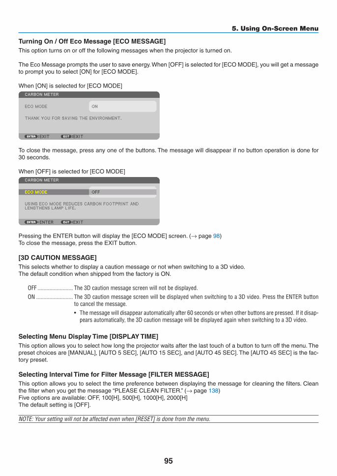
95
5. Using On-Screen Menu
TurningOn/OffEcoMessage[ECOMESSAGE]Thisoptionturnsonoroffthefollowingmessageswhentheprojectoristurnedon.
TheEcoMessagepromptstheusertosaveenergy.When[OFF]isselectedfor[ECOMODE],youwillgetamessagetopromptyoutoselect[ON]for[ECOMODE].
When[ON]isselectedfor[ECOMODE]
Toclosethemessage,pressanyoneofthebuttons.Themessagewilldisappearifnobuttonoperationisdonefor30seconds.
When[OFF]isselectedfor[ECOMODE]
PressingtheENTERbuttonwilldisplaythe[ECOMODE]screen.(→page98)Toclosethemessage,presstheEXITbutton.
[3D CAUTION MESSAGE]Thisselectswhethertodisplayacautionmessageornotwhenswitchingtoa3Dvideo.ThedefaultconditionwhenshippedfromthefactoryisON.
OFF ������������������������ The 3D caution message screen will not be displayed�ON ������������������������� The 3D caution message screen will be displayed when switching to a 3D video� Press the ENTER button
to cancel the message�• Themessagewilldisappearautomaticallyafter60secondsorwhenotherbuttonsarepressed.Ifitdisap-
pears automatically, the 3D caution message will be displayed again when switching to a 3D video�
SelectingMenuDisplayTime[DISPLAYTIME]Thisoptionallowsyoutoselecthowlongtheprojectorwaitsafterthelasttouchofabuttontoturnoffthemenu.Thepresetchoicesare[MANUAL],[AUTO5SEC],[AUTO15SEC],and[AUTO45SEC].The[AUTO45SEC]isthefac-torypreset.
Selecting Interval Time for Filter Message [FILTER MESSAGE]Thisoptionallowsyoutoselectthetimepreferencebetweendisplayingthemessageforcleaningthefilters.Cleanthefilterwhenyougetthemessage“PLEASECLEANFILTER.”(→page138)Fiveoptionsareavailable:OFF,100[H],500[H],1000[H],2000[H]Thedefaultsettingis[OFF].
NOTE:Yoursettingwillnotbeaffectedevenwhen[RESET]isdonefromthemenu.

96
5. Using On-Screen Menu
[INSTALLATION]
Selecting Projector Orientation [ORIENTATION]Thisreorientsyourimageforyourtypeofprojection.Theoptionsare:desktopfrontprojection,ceilingrearprojection,desktoprearprojection,andceilingfrontprojection.
NOTE: • Pleaseconsulttheretailstoreifyourequirespecialinstallationservicese.g.whenmountingtheprojectortoaceiling.Neverinstall
the projector on your own. This may result in the projector falling down and causing injury to people.• Whenusingtheprojectorsuspendedfromaceiling,ensurethatpeopledonotstaybelowtheprojector.Intheeventthelamp
were to break, there is a risk that glass fragments may fall from the projector.
AUTO ��������������������� This automatically detects and projects the DESKTOP FRONT and CEILING FRONT�
NOTE:• TheDESKTOPREARandCEILINGREARwillnotbedetected.Pleaseselectmanually.
DESKTOPFRONT CEILINGREAR
DESKTOPREAR CEILINGFRONT
TIP:• CheckwhethertheautomaticDESKTOPFRONTisinstalledwithin±10degreesforfloorinstallationandwhethertheCEILING
FRONTiswithin±10degreesforceilinginstallation.Selectmanuallywhentheprojectionscreenisinverted.
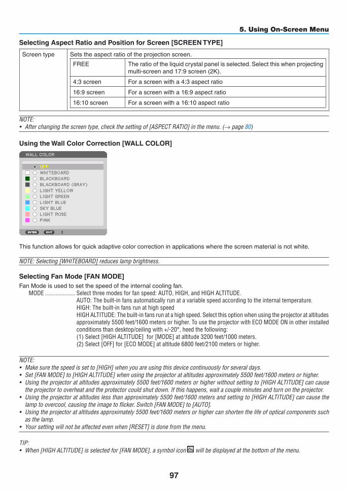
97
5. Using On-Screen Menu
Selecting Aspect Ratio and Position for Screen [SCREEN TYPE]
Screentype Setstheaspectratiooftheprojectionscreen.
FREE Theratiooftheliquidcrystalpanelisselected.Selectthiswhenprojectingmulti-screenand17:9screen(2K).
4:3screen Forascreenwitha4:3aspectratio
16:9screen Forascreenwitha16:9aspectratio
16:10screen Forascreenwitha16:10aspectratio
NOTE:• Afterchangingthescreentype,checkthesettingof[ASPECTRATIO]inthemenu.(→ page 80)
Using the Wall Color Correction [WALL COLOR]
Thisfunctionallowsforquickadaptivecolorcorrectioninapplicationswherethescreenmaterialisnotwhite.
NOTE:Selecting[WHITEBOARD]reduceslampbrightness.
Selecting Fan Mode [FAN MODE]FanModeisusedtosetthespeedoftheinternalcoolingfan.
MODE �������������������� Select three modes for fan speed: AUTO, HIGH, and HIGH ALTITUDE�AUTO: The built-in fans automatically run at a variable speed according to the internal temperature�HIGH: The built-in fans run at high speedHIGH ALTITUDE: The built-in fans run at a high speed� Select this option when using the projector at altitudes approximately 5500 feet/1600 meters or higher� To use the projector with ECO MODE ON in other installed conditions than desktop/ceiling with +/-20°, heed the following:(1) Select [HIGH ALTITUDE] for [MODE] at altitude 3200 feet/1000 meters�(2) Select [OFF] for [ECO MODE] at altitude 6800 feet/2100 meters or higher�
NOTE: • Makesurethespeedissetto[HIGH]whenyouareusingthisdevicecontinuouslyforseveraldays.•Set[FANMODE]to[HIGHALTITUDE]whenusingtheprojectorataltitudesapproximately5500feet/1600metersorhigher.• Usingtheprojectorataltitudesapproximately5500feet/1600metersorhigherwithoutsettingto[HIGHALTITUDE]cancause
the projector to overheat and the protector could shut down. If this happens, wait a couple minutes and turn on the projector.•Usingtheprojectorataltitudeslessthanapproximately5500feet/1600metersandsettingto[HIGHALTITUDE]cancausethe
lamptoovercool,causingtheimagetoflicker.Switch[FANMODE]to[AUTO].•Usingtheprojectorataltitudesapproximately5500feet/1600metersorhighercanshortenthelifeofopticalcomponentssuch
as the lamp.• Yoursettingwillnotbeaffectedevenwhen[RESET]isdonefromthemenu.
TIP: • When[HIGHALTITUDE]isselectedfor[FANMODE],asymbolicon will be displayed at the bottom of the menu.

98
5. Using On-Screen Menu
[LAMP MODE]Wheneco-modeissetto[ON],theCO2emissions(calculatedfromthereductioninpowerconsumption)oftheprojec-torcanbereduced.Theeco-modereducespowerconsumptionbymainlyloweringthebrightnessofthelamp.Asaresult,thelampreplacementtime(asaguide)*isextended.(→page118)* Replacementtimenotguaranteed.
LAMP ADJUST ������� This can be set when the eco-mode is set to [OFF]� Adjust the lamp to match the brightness of each projector when projecting a multi-screen display using multiple projectors�
ECOMODE OFF Thelampluminance(brightness)willbecome100%andthescreenwillturnbright.Theluminanceofthelampcanbesetusingthelampadjustment.
ON Thelampluminance(brightness)willbecomeapproximately80%andthelampreplacementtime(estimated)*willbeextended.* Thereplacementtimeisnotguaranteed.
LAMPADJUST Whenthe[ECOMODE]issetto[OFF],[LAMPADJUST]isenabled.Adjustthelamptomatchthebrightnessofeachprojectorwhenprojectingamulti-screendisplayusingmultipleprojectors.
[REF. WHITE BALANCE]Thisfeatureallowsyoutoadjustthewhitebalanceforallsignals.Thewhiteandblacklevelsofthesignalareadjustedforoptimumcolorreproduction.Uniformityisalsoadjustedwhentheredness(R)andblueness(B)ofthewhitecolorinthescreen’shorizontal(left/right)directionareuneven.
CONTRAST R/CONTRAST G/CONTRAST B ������������������������������ These adjust the picture’s white color�BRIGHTNESS R/BRIGHTNESS G/BRIGHTNESS B ������������������������������ These adjust the picture’s black color�UNIFORMITY R ������ The further this is set to the + side, the stronger the redness on the left side of the picture (increasing
towards the left edge) and the weaker the redness on the right side of the picture (decreasing towards the right edge)�This is reversed when set to the – side�
UNIFORMITY B ������ The further this is set to the + side, the stronger the blueness on the left side of the picture (increasing towards the left edge) and the weaker the blueness on the right side of the picture (decreasing towards the right edge)�This is reversed when set to the – side�
[STATICCONVERGENCE]Thisfeaturesallowsyoutoadjustforcolordeviationinthepicture.Thiscanbeadjustedinunitsof±1pixelinthehorizontaldirectionforHORIZONTALR,GandB,intheverticaldirec-tionforVERTICALR,GandB.
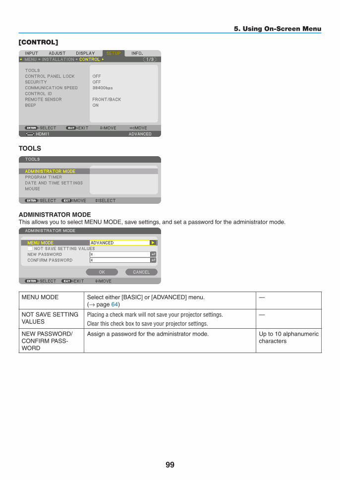
99
5. Using On-Screen Menu
[CONTROL]
TOOLS
ADMINISTRATOR MODEThisallowsyoutoselectMENUMODE,savesettings,andsetapasswordfortheadministratormode.
MENUMODE Selecteither[BASIC]or[ADVANCED]menu.(→page64)
—
NOTSAVESETTINGVALUES
Placing a check mark will not save your projector settings�Clear this check box to save your projector settings�
—
NEWPASSWORD/CONFIRMPASS-WORD
Assignapasswordfortheadministratormode. Upto10alphanumericcharacters

100
5. Using On-Screen Menu
PROGRAM TIMER
Thisoption turnson/standby theprojectorandchangesvideosignals,andselectsECOmodeautomaticallyataspecifiedtime.
NOTE:• Beforeusing[PROGRAMTIMER],makesurethatthe[DATEANDTIME]featureisset.(→ page 103) MakesurethattheprojectorisinthestandbyconditionwiththePOWERcordconnected. The projector has a built-in clock. The clock will keep working for about two weeks after the main power is turned off. If the main
power is not supplied to the projector for two weeks or more, the built-in clock stops working.
Setting a new program timer1. On the PROGRAM TIMER screen, use the ▲ or ▼buttontoselect[SETTINGS]andpresstheENTERbut-
ton.
The[PROGRAMLIST]screenwillbedisplayed.
2. Select a blank program number and press the ENTER button.
The[EDIT]screenwillbedisplayed.
3. Make settings for each item as required.
ACTIVE ������������������ Place a check mark to enable the program�DAY ������������������������ Select days of the week for the program timer� To execute the program from Monday to Friday, select [MON-
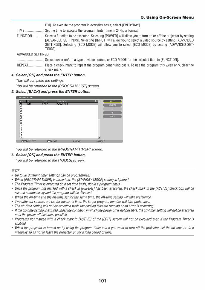
101
5. Using On-Screen Menu
FRI]� To execute the program in everyday basis, select [EVERYDAY]�TIME ���������������������� Set the time to execute the program� Enter time in 24-hour format�FUNCTION ������������� Select a function to be executed� Selecting [POWER] will allow you to turn on or off the projector by setting
[ADVANCED SETTINGS]� Selecting [INPUT] will allow you to select a video source by setting [ADVANCED SETTINGS]� Selecting [ECO MODE] will allow you to select [ECO MODE] by setting [ADVANCED SET-TINGS]�
ADVANCED SETTINGS ������������������������������ Select power on/off, a type of video source, or ECO MODE for the selected item in [FUNCTION]�REPEAT ������������������ Place a check mark to repeat the program continuing basis� To use the program this week only, clear the
check mark�4. Select[OK]andpresstheENTERbutton.
Thiswillcompletethesettings.
Youwillbereturnedtothe[PROGRAMLIST]screen.
5. Select[BACK]andpresstheENTERbutton.
Youwillbereturnedtothe[PROGRAMTIMER]screen.
6. Select[OK]andpresstheENTERbutton.
Youwillbereturnedtothe[TOOLS]screen.
NOTE:• Upto30differenttimersettingscanbeprogrammed.• When[PROGRAMTIMER]isturnedon,the[STANDBYMODE]settingisignored.• TheProgramTimerisexecutedonasettimebasis,notinaprogrambasis.• Oncetheprogramnotmarkedwithacheckin[REPEAT]hasbeenexecuted,thecheckmarkinthe[ACTIVE]checkboxwillbe
cleared automatically and the program will be disabled.• Whentheon-timeandtheoff-timesetforthesametime,theoff-timesettingwilltakepreference.• Twodifferentsourcesaresetforthesametime,thelargerprogramnumberwilltakepreference.• Theon-timesettingwillnotbeexecutedwhilethecoolingfansarerunningoranerrorisoccurring.• Iftheoff-timesettingisexpiredundertheconditioninwhichthepoweroffisnotpossible,theoff-timersettingwillnotbeexecuted
until the power off becomes possible.• Programsnotmarkedwithacheckmarkin[ACTIVE]ofthe[EDIT]screenwillnotbeexecutedeveniftheProgramTimeris
enabled.• Whentheprojectoristurnedonbyusingtheprogramtimerandifyouwanttoturnofftheprojector,settheoff-timeordoit
manually so as not to leave the projector on for a long period of time.

102
5. Using On-Screen Menu
Activating the program timer
1. Select[ENABLE]onthe[PROGRAMTIMER]screenandpresstheENTERbutton.
Theselectionscreenwillbedisplayed.
2. Press the ▼buttontoalignthecursorwith[ON]andthenpresstheENTERbutton.
Returntothe[PROGRAMTIMER]screen.
NOTE:• Whentheeffectivesettingsofthe[PROGRAMTIMER]havenotbeensetto[ON],theprogramwillnotbeexecutedevenifthe
[ACTIVE]itemsintheprogramlisthavebeenticked.• Evenwhentheeffectivesettingsofthe[PROGRAMTIMER]aresetto[ON],the[PROGRAMTIMER]willnotworkuntilthe[PRO-
GRAMTIMER]screenisclosed.
Changing the programmed settings
1. Onthe[PROGRAMLIST]screen,selectaprogramyouwanttoeditandpresstheENTERbutton.
2. Changethesettingsonthe[EDIT]screen.
3. Select[OK]andpresstheENTERbutton.
Theprogrammedsettingswillbechanged.
Youwillbereturnedtothe[PROGRAMLIST]screen.
Changing the order of programs
1. Onthe[PROGRAMLIST]screen,selectaprogramwhoseorderyouwanttochangeandpressthe▶ but-ton.
2. Press the ▼ button to select ▲ or ▼.
3. Press the ENTER button a few times to select a row to which you wish to move the program.
Theorderoftheprogramswillbechanged.
Deleting the programs
1. Onthe[PROGRAMLIST]screen,selectaprogramnumberyouwanttodeleteandpressthe▶ button.
2. Press the ▼buttontoselect[DELETE].
3. Press the ENTER button.
Theconfirmationscreenwillbedisplayed.
4. Select[YES]andpresstheENTERbutton.
Theprogramwillbedeleted.
Thiswillcompletedeletingtheprogram.
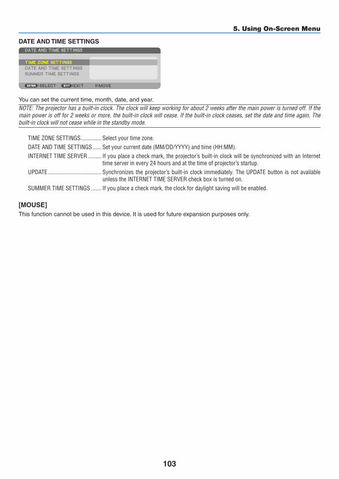
103
5. Using On-Screen Menu
DATE AND TIME SETTINGS
Youcansetthecurrenttime,month,date,andyear.NOTE:Theprojectorhasabuilt-inclock.Theclockwillkeepworkingforabout2weeksafterthemainpoweristurnedoff.Ifthemainpowerisofffor2weeksormore,thebuilt-inclockwillcease.Ifthebuilt-inclockceases,setthedateandtimeagain.Thebuilt-in clock will not cease while in the standby mode.
TIME ZONE SETTINGS �������������� Select your time zone�DATE AND TIME SETTINGS ������ Set your current date (MM/DD/YYYY) and time (HH:MM)� INTERNET TIME SERVER ��������� If you place a check mark, the projector’s built-in clock will be synchronized with an Internet
time server in every 24 hours and at the time of projector’s startup�UPDATE ������������������������������������ Synchronizes the projector’s built-in clock immediately� The UPDATE button is not available
unless the INTERNET TIME SERVER check box is turned on�SUMMER TIME SETTINGS ������� If you place a check mark, the clock for daylight saving will be enabled�
[MOUSE]Thisfunctioncannotbeusedinthisdevice.Itisusedforfutureexpansionpurposesonly.

104
5. Using On-Screen Menu
DisablingtheCabinetButtons[CONTROLPANELLOCK]ThisoptionturnsonorofftheCONTROLPANELLOCKfunction.
NOTE:• Howtocancelthe[CONTROLPANELLOCK] Whenthe[CONTROLPANELLOCK]issetto[ON],presstheEXITbuttonortheINPUTbuttononthemainbodyforabout10
secondstocancelthe[CONTROLPANELLOCK]setting.
TIP: • Whenthe[CONTROLPANELLOCK]isturnedon,akeylockicon[ ]willbedisplayedatthebottomrightofthemenu.• ThisCONTROLPANELLOCKdoesnotaffecttheremotecontrolfunctions.
EnablingSecurity[SECURITY]ThisfeatureturnsonorofftheSECURITYfunction.Unlessthecorrectkeywordisentered,theprojectorcannotprojectanimage.(→page36)
NOTE:Yoursettingwillnotbeaffectedevenwhen[RESET]isdonefromthemenu.
Selecting Communication Speed [COMMUNICATION SPEED]ThisfeaturesetsthebaudrateofthePCControlport(D-Sub9P).Itsupportsdataratesfrom4800to115200bps.Thedefaultis38400bps.Selecttheappropriatebaudrateforyourequipmenttobeconnected(dependingontheequipment,alowerbaudratemayberecommendedforlongcableruns).
NOTE:• Select[38400bps]orlesswhenusingthesuppliedsoftwareprograms.• Yourselectedcommunicationspeedwillnotbeaffectedevenwhen[RESET]isdonefromthemenu.

105
5. Using On-Screen Menu
Setting ID to the Projector [CONTROL ID]YoucanoperatemultipleprojectorsseparatelyandindependentlywiththesingleremotecontrolthathastheCONTROLIDfunction.IfyouassignthesameIDtoalltheprojectors,youcanconvenientlyoperatealltheprojectorstogetherusingthesingleremotecontrol.Todoso,youhavetoassignanIDnumbertoeachprojector.
CONTROL ID NUMBER �������Select a number from 1 to 254 you wish to assign to your projector�CONTROL ID �����������������������Select [OFF] to turn off the CONTROL ID setting and select [ON] to turn on the CONTROL ID set-
ting�
NOTE: • When[ON]isselectedfor[CONTROLID],theprojectorcannotbeoperatedbyusingtheremotecontrolthatdoesnotsupport
theCONTROLIDfunction.(Inthiscasethebuttonsontheprojectorcabinetcanbeused.)• Yoursettingwillnotbeaffectedevenwhen[RESET]isdonefromthemenu.•PressingandholdingtheENTERbuttonontheprojectorcabinetfor10secondswilldisplaythemenuforcancelingtheControl
ID.
Assigning or Changing the Control ID1. Turn on the projector.
2. Press the ID SET button on the remote control.
TheCONTROLIDscreenwillbedisplayed.
IftheprojectorcanbeoperatedwiththecurrentremotecontrolID,the[AC-TIVE]willbedisplayed.IftheprojectorcannotbeoperatedwiththecurrentremotecontrolID,the[INACTIVE]willbedisplayed.Tooperatetheinactiveprojector,assignthecontrolIDusedfortheprojectorbyusingthefollowingprocedure(Step3).
3. Press one of numeric keypad buttons while pressing and holding the ID SET button on the remote control.
Example:
Toassign“3”,pressthe“3”buttonontheremotecontrol.
NoIDmeansthatalltheprojectorscanbeoperatedtogetherwithasingleremotecontrol.Toset“NoID”,enter“000”orpresstheCLEARbutton.
TIP:TherangeofIDsisfrom1to254.4. Release the ID SET button.
TheupdatedCONTROLIDscreenwillbedisplayed.
NOTE: •TheIDscanbeclearedinafewdaysafterthebatteriesarerundownorremoved.•Accidentallypressinganyoneofthebuttonsoftheremotecontrolwillclearcurrently
specifiedIDwithbatteriesremoved.

106
5. Using On-Screen Menu
Turning On or Off Remote Sensor [REMOTE SENSOR]Thisoptiondetermineswhichremotesensorontheprojectorisenabledinwirelessmode.Theoptionsare:FRONT/BACK,FRONT,BACK,andHDBaseT.
NOTE:• TheremotecontroloftheprojectorwillnotbeabletoreceivesignalsifthepowersupplyoftheHDBaseTtransmissiondevice
connectedtotheprojectorisswitchedonwhenthishasbeensetto“HDBaseT”.
TIP:• Iftheremotecontrolsystemdoesnotfunctionwhendirectsunlightorstrongilluminationstrikestheremotecontrolsensorof
the projector, change another option.
EnablingKeySoundandErrorSound[BEEP]This feature turnsonoroff thebuttonsoundoralarmwhenanerroroccursor the followingoperationsareper-formed.
• Displayingthemainmenu
• Switchingsources
• Resettingdatabyusing[RESET]
• PressingPOWERONorSTANDBYbutton

107
5. Using On-Screen Menu
[NETWORK SETTINGS]
Important:• Consultwithyournetworkadministratoraboutthesesettings.• WhenusingawiredLANconnection,connectaLANcable(Ethernetcable)totheLANport(RJ-45)oftheprojector.(→ page
137)
TIP:Thenetworksettingsyoumakewillnotbeaffectedevenwhen[RESET]isdonefromthemenu.
Hints on How to Set Up LAN Connection
To set up the projector for a LAN connection:Select[WIREDLAN]→[PROFILES]→[PROFILE1]or[PROFILE2].TwosettingscanbesetforwiredLAN.Nextturnonorofffor[DHCP],[IPADDRESS],[SUBNETMASK],and[GATEWAY]andselect[OK]andpresstheENTERbutton.(→page108)TorecallLANsettingsstoredintheprofilenumber:Select[PROFILE1]or[PROFILE2]forwiredLAN,andthenselect[OK]andpresstheENTERbutton.(→page108)To connect a DHCP server:Turnon[DHCP]forwiredLAN.Select[ON]andpresstheENTERbutton.TospecifyIPaddresswithoutusingtheDHCPserver,turnoff[DHCP].(→page108)
To receive lamp replacement time or error messages via e-mail:Select[ALERTMAIL],andset[SENDER'SADDRESS],[SMTPSERVERNAME],and[RECIPIENT'SADDRESS].Last,select[OK]andpresstheENTERbutton.(→page110)

108
5. Using On-Screen Menu
WIRED LAN
PROFILES • Thesettings forusing thebuilt-inEthernet/HDBaseTport intheprojectorcanberecordedintheprojectormemoryintwoways.• Select[PROFILE1]or[PROFILE2]andthendosettingsfor[DHCP]andtheotheroptions. Afterdoingthis,select[OK]andpresstheENTERbutton.Thiswillstoreyoursettingsinmemory.• Torecallthesettingsfrommemory: Afterselecting[PROFILE1]or[PROFILE2]fromthe[PRO-FILES]list. Select[OK]andpresstheENTERbutton.• Select[DISABLE]whennotconnectingtoawiredLAN
—
DHCP PlaceacheckmarktoautomaticallyassignanIPaddresstotheprojectorfromyourDHCPserver.ClearthischeckboxtoregistertheIPaddressorsubnetmasknumberobtainedfromyournetworkadministrator.
—
IPADDRESS SetyourIPaddressofthenetworkconnectedtotheprojectorwhen[DHCP]isturnedoff.
Upto12numericcharacters
SUBNETMASK Setyoursubnetmasknumberofthenetworkconnectedtotheprojectorwhen[DHCP]isturnedoff.
Upto12numericcharacters
GATEWAY Setthedefaultgatewayofthenetworkconnectedtotheprojectorwhen[DHCP]isturnedoff.
Upto12numericcharacters
AUTODNS PlaceacheckmarktoautomaticallyassigntheIPaddressofyourDNSserverconnectedtotheprojectorfromyourDHCPserver.ClearthischeckboxtosettheIPaddressofyourDNSserverconnectedtotheprojector.
Upto12numericcharacters
DNSCONFIGURA-TION
SettheIPaddressofyourDNSserveronthenetworkconnectedtotheprojectorwhen[AUTODNS]iscleared.
Upto12numericcharacters
RECONNECT Retrytoconnecttheprojectortoanetwork.Trythisifyouhavechanged[PROFILES].
—

109
5. Using On-Screen Menu
PROJECTOR NAME
PROJECTORNAME Setauniqueprojectorname. Upto16alphanu-mericcharactersandsymbols
DOMAINSetahostnameanddomainnameoftheprojector.
HOSTNAME Setahostnameoftheprojector. Upto15alphanumericcharacters
DOMAINNAME Setadomainnameoftheprojector. Upto60alphanumericcharacters

110
5. Using On-Screen Menu
ALERT MAIL
ALERTMAIL Thisoptionwillnotifyyourcomputeroflampreplacetimeorerrormessagesviae-mailwhenusingwirelessorwiredLAN.
Placing a checkmark will turn on the Alert Mail feature�Clearing a checkmark will turn off the Alert Mail feature�
Sample of a message to be sent from the projector:
Thelampandfiltersareat theendof itsusable life.Pleasereplacethelampandfilters.ProjectorName:NECProjectorLampHoursUsed:100[H]
—
HOSTNAME Typeinahostname. Upto15alphanumericcharacters
DOMAINNAME Typeinadomainnameofthenetworkconnectedtotheprojec-tor.
Upto60alphanumericcharacters
SENDER'SAD-DRESS
Specifythesender’saddress. Upto60alphanu-mericcharactersandsymbols
SMTPSERVERNAME
TypeintheSMTPservernametobeconnectedtotheprojec-tor.
Upto60alphanumericcharacters
RECIPIENT'SAD-DRESS1,2,3
Typeinyourrecipient’saddress. Upto60alphanu-mericcharactersandsymbols
TESTMAIL Sendatestmailtocheckifyoursettingsarecorrect.NOTE:• Ifyouenteredanincorrectaddressinatest,youmaynotreceivean
Alert mail. Should this happen, check if the Recipient’s Address iscorrectly set.
• Unless any one of the [SENDER'S ADDRESS], [SMTP SERVER'SNAME]or[RECIPIENT'SADDRESS1-3]isselected,[TESTMAIL]isnot available.
• Besuretohighlight[OK]andpresstheENTERbuttonbeforeexecuting[TESTMAIL].
—

111
5. Using On-Screen Menu
NETWORKSERVICE
HTTPSERVER SetapasswordforyourHTTPserver. Upto10alphanumericcharacters
PJLink This option allows you to set a passwordwhen you use thePJLinkfeature.NOTE: • Donotforgetyourpassword.However,ifyouforgetyourpassword,
consult with your dealer. • WhatisPJLink? PJLinkisastandardizationofprotocolusedforcontrollingprojectors
of different manufacturers. This standard protocol is established by JapanBusinessMachineandInformationSystemIndustriesAssocia-tion(JBMIA)in2005.
TheprojectorsupportsallthecommandsofPJLinkClass1.• SettingofPJLinkwillnotbeaffectedevenwhen[RESET]isdonefrom
the menu.
Upto32alphanumericcharacters
AMXBEACON Turnonoroff fordetection fromAMXDeviceDiscoverywhenconnectingtothenetworksupportedbyAMX’sNetLinxcontrolsystem.
TIP: WhenusingadevicethatsupportsAMXDeviceDiscovery,allAMXNetLinxcontrol system will recognize the device and download the appropriate DeviceDiscoveryModulefromanAMXserver.
Placing a checkmark will enable detecting the projector from AMX Device Discovery�Clearing a checkmark will disable detecting the projector from AMX Device Discovery�
—

112
5. Using On-Screen Menu
[SOURCE OPTIONS]
Setting Auto Adjust [AUTO ADJUST]ThisfeaturesetstheAutoAdjustmodesothatthecomputersignalcanbeautomaticallyormanuallyadjustedfornoiseandstability.Youcanautomaticallymakeadjustmentintwoways:[NORMAL]and[FINE].
OFF ������������������������ The computer signal will not be automatically adjusted� You can manually optimize the computer signal�NORMAL ���������������� Default setting� The computer signal will be automatically adjusted� Normally select this option�FINE ����������������������� Select this option if fine adjustment is needed� It takes more time to switch to the source than when [NOR-
MAL]is selected�
TIP:• Thedefaultsettingwhenshippedfromthefactoryis[NORMAL].• WhentheAUTOADJ.buttonispressed,thesame[FINE]adjustmentiscarriedout.
[COLOR SYSTEM]ThisfeatureallowsyoutoselecttheTVvideosignal,whichdiffersfromcountrytocountry(NTSC,PAL,etc.).Thisissetto[AUTO]byfactorydefault.Setthisiftheprojectorcannotidentifythesignalautomatically.
[AUDIO SELECT]ThisselectstheaudioinputoftheHDMI1INterminal,HDMI2INterminal,DisplayPortinputterminalandEthernet/HDBaseTport.Wheninputtinganalogaudio,connecttheaudiooutputterminaloftheconnectingdevicewiththeBNCaudioinputterminalandsettheAudioSelectto“BNC”.
Selecting Default Source [DEFAULT INPUT SELECT]Youcansettheprojectortodefaulttoanyoneofitsinputseachtimetheprojectoristurnedon.
LAST ���������������������� Sets the projector to default to the previous or last active input each time the projector is turned on�AUTO ��������������������� Searches for an active source in order of HDMI1 → HDMI2 → DisplayPort → BNC → BNC(CV) → BNC(Y/C)
→ COMPUTER → HDBaseT and displays the first found source�HDMI1 ������������������� Displays the digital source from the HDMI 1 IN connector every time the projector is turned on� HDMI2 ������������������� Displays the digital source from the HDMI 2 IN connector every time the projector is turned on� DisplayPort ������������ Displays the digital source from the DisplayPort every time the projector is turned on� BNC ����������������������� Project the input signal from the BNC video input terminalBNC(CV) ���������������� Project the input signal from the BNC(CV) video input terminal�BNC(Y/C) ��������������� Project the input signal from the BNC(Y/C) video input terminal�COMPUTER ����������� Displays the computer signal from the COMPUTER IN connector every time the projector is turned on�HDBaseT ���������������� Project the HDBaseT signal�

113
5. Using On-Screen Menu
[SEAMLESS SWITCHING]Whentheinputconnectorisswitched,theimagedisplayedbeforeswitchingisheldtoswitchtothenewimagewithoutabreakduetoabsenceofasignal.
Setting Closed Caption [CLOSED CAPTION]ThisoptionsetsseveralclosedcaptionmodesthatallowtexttobesuperimposedontheprojectedimageofVideoorS-Video.Thesubtitlesandtextwillbedisplayedashortwhileaftertheon-screenmenudisappears.
OFF ������������������������ This exits the closed caption mode�CAPTION 1-4 ��������� Text is superimposed�TEXT 1-4 ���������������� Text is displayed�
SelectingaColororLogoforBackground[BACKGROUND]Use this feature to display a blue/black screen or logowhen no signal is available.The default background is[BLUE].
NOTE: • Evenwhenthebackgroundlogoisselected,iftwopicturesaredisplayedin[PIP/PICTUREBYPICTURE]mode,thebluebackground
is displayed without the logo when there is no signal.

114
5. Using On-Screen Menu
[POWER OPTIONS]
Selecting Power-saving in [STANDBY MODE]Settingthepowerconsumptioninthestandbymode.
NORMAL ���������������� In the standby mode, the power consumption of the projector is 0�11 W (100-130 V)/0�16 W (200-240 V)�In the standby mode, the POWER indicator lights up in red while the STATUS indicator will go off�• Whensetto[NORMAL],thefollowingterminalsandfunctionswillbedisabled.HDMIoutputterminals,
audio output terminals, Ethernet/HDBaseT port, USB-A port, LAN function, mail notification functionHDBaseT STANDBY ������������������������������ Compared to [NORMAL], the power consumption in the standby mode is higher but power can be supplied
to the projector using a wired LAN�In the standby mode, the power indicator will light up in orange while the status indicator will be turned off�
Important:• When[HDBaseTSTANDBY]isselected,[AUTOPOWEROFF]willturngreyincolorandbedisabledand[0:15]willbeselected
automatically.• Inthefollowingconditions,the[STANDBYMODE]settingwillbedisabledandtheprojectorwillgointothesleepmode.
* Sleepmodereferstothemodewherebythefunctionalrestrictionsduetothe[STANDBYMODE]settingareremoved.• When[ENABLE]isselectedunder[NETWORKSERVICE]→[AMXBEACON]• When[HDBaseT]isselectedunder[CONTROL]→[REMOTESENSOR]• WhenasignalisbeingreceivedfromaHDBaseTtransmissiondevice
• When[NORMAL]isselected,the[AUTOPOWERONSELECT]displayturnsgreyincolorandisdisabled,and[OFF]isautomati-cally selected.
NOTE:• WhenconnectingtoaHDBaseTtransmissiondevicesoldcommercially,ifthetransmissiondeviceissettotransmitremotecontrol
signals, the power consumption of the projector in the standby mode will increase.
TIP: • Yoursettingwillnotbeaffectedevenwhen[RESET]isdonefromthemenu.• ThepowerconsumptioninthestandbymodewillnotbeincludedincalculatingCO2 emission reduction.
Enabling Direct Power On [DIRECT POWER ON]Turnstheprojectoronautomaticallywhenthepowercordisinsertedintoanactivepoweroutlet.ThiseliminatestheneedtoalwaysusethePOWERbuttonontheremotecontrolorprojectorcabinet.

115
5. Using On-Screen Menu
TurningOntheProjectorByApplyingComputerSignal[AUTOPOWERONSELECT]Thissettingautomaticallyprojectsanycomputersignalthatisinputwhentheprojectorisinthestandbymode.Connecttotheinputterminalontheprojectorusingacableandputtheprojectorinthestandbymode.Whenusingthe[AUTOPOWERONSELECT],setthe[STANDBYMODE]to[HDBaseTSTANDBY],turnonthepowersupplyofthetransmissiondeviceandkeepitinaconnectedstate.
OFF ������������������������ AUTO POWER ON SELECT function will be switch off�HDMI1, HDMI2, DisplayPort, COMPUTER, HDBaseT ������������������������������ When a computer signal of a selected input terminal is detected, the power supply of the projector will be
turned on automatically and the computer screen will be projected�
NOTE: • ThisfunctionwillnotworkforcomputersignalssuchasSynconGreenorCompositeSyncandwhencomponentsignalsare
inputtothecomputerorBNCvideoinputterminal.• IfyouwanttotesttheAUTOPOWERONSELECTafterswitchingoffthepowersupplyoftheprojector,waitforthreeormore
secondsfirstafterswitchingoffthepowerbeforeinputtinganycomputersignal.Whenthepowersupplyisswitchedoffandtheprojector goes into the standby mode, the projector will continue to remain in the standby mode without power supply being restored if a computer signal continues to be input to the projector.
Enabling Power Management [AUTO POWER OFF]Whenthisoptionisselectedyoucanenabletheprojectortoautomaticallyturnoff(attheselectedtime:0:05,0:10,0:15,0:20,0:30,1:00)ifthereisnosignalreceivedbyanyinputorifnooperationisperformed.
NOTE:• ThepowerwillnotgooffautomaticallywhenasignalfromtheEthernet/HDBaseTportisbeingprojected.• [AUTOPOWEROFF]appearsingreywhenthe[STANDBYMODE]issetto[HDBaseTSTANDBY]and[0:15]willbesetautomati-
cally.
Using Off Timer [OFF TIMER]1. Select your desired time between 30 minutes and 16 hours: OFF, 0:30, 1:00, 2:00, 4:00, 8:00, 12:00, 16:00.
2. Press the ENTER button on the remote control.
3. The remaining time starts counting down.
4. The projector will turn off after the countdown is complete.
NOTE:• Tocancelthepresettime,set[OFF]forthepresettimeorturnoffthepower.• Whentheremainingtimereaches3minutesbeforetheprojectoristurnedoff,the[THEPROJECTORWILLTURNOFFWITHIN3
MINUTES]messagewillbedisplayedonthebottomofthescreen.

116
5. Using On-Screen Menu
Returning to Factory Default [RESET]TheRESETfeatureallowsyoutochangeadjustmentsandsettingstothefactorypresetfora(all)source(s)exceptthefollowing:
[CURRENT SIGNAL]Resetstheadjustmentsforthecurrentsignaltothefactorypresetlevels.Theitemsthatcanberesetare:[PRESET],[CONTRAST],[BRIGHTNESS],[COLOR],[HUE],[SHARPNESS],[AS-PECTRATIO],[HORIZONTAL],[VERTICAL],[CLOCK],[PHASE],and[OVERSCAN].
[ALL DATA]Resetalltheadjustmentsandsettingsforallthesignalstothefactorypreset.AllitemscanberesetEXCEPT[LANGUAGE],[BACKGROUND],[FILTERMESSAGE],[EDGEBLENDING],[MULTISCREEN],[SCREENTYPE],[GEOMETRICCORRECTION],[REF.WHITEBALANCE],[STATICCONVERGENCE],[ADMINISTRATORMODE], [CONTROLPANELLOCK], [SECURITY], [COMMUNICATIONSPEED], [CONTROLID],[STANDBYMODE],[FANMODE],[LAMPLIFEREMAINING],[LAMPHOURSUSED],[FILTERHOURSUSED],[TOTALCARBONSAVINGS],and[WIREDLAN].Toresetthelampusagetime,see“ClearingLampHourMeter[CLEARLAMPHOURS]”below.
[ALLDATA(INCLUDINGENTRYLIST)]Resetalltheadjustmentsandsettingsforallthesignalstothefactorypresetexcept[LANGUAGE],[BACKGROUND],[FILTERMESSAGE],[EDGEBLENDING],[MULTISCREEN],[SCREENTYPE],[GEOMETRICCORRECTION],[REF.WHITEBALANCE],[STATICCONVERGENCE],[ADMINISTRATORMODE],[CONTROLPANELLOCK],[SECURITY],[COMMUNICATIONSPEED],[CONTROLID],[STANDBYMODE],[FANMODE],[LAMPLIFEREMAINING],[LAMPHOURSUSED],[FILTERHOURSUSED],[TOTALCARBONSAVINGS],and[WIREDLAN].Alsodeletesallthesignalsinthe[ENTRYLIST]andreturnstothefactorypreset.
NOTE:LockedsignalsinEntryListcannotbereset.
Clearing Lamp Hour Meter [CLEAR LAMP HOURS]Resetsthelampclockbacktozero.Selectingthisoptiondisplayssubmenuforaconfirmation.Select[YES]andpresstheENTERbutton.
NOTE: • Elapsedtimeofthelampusewillnotbeaffectedevenwhen[RESET]isdonefromthemenu.• Performing[CLEARLAMPHOURS]willreturnthe[LAMPADJUST]in[LAMPMODE]toitsdefaultadjustments.Whentheprojec-
torisusedformulti-screenprojection,use[LAMPADJUST]toadjustthebrightnessagain.

117
5. Using On-Screen Menu
Clearing the Filter Usage Hours [CLEAR FILTER HOURS]Resetsthefilterusagebacktozero.Selectingthisoptiondisplayssubmenuforaconfirmation.Select[YES]andpresstheENTERbutton.
The[OFF]itemisselectedfor[FILTERMESSAGE]atthetimeofshipment.When[OFF]isselected,youdonotneedtoclearthefilterusagehour.
NOTE:Elapsedtimeofthefilterusewillnotbeaffectedevenwhen[RESET]isdonefromthemenu.

118
5. Using On-Screen Menu
❽ Menu Descriptions & Functions [INFO.]Displaysthestatusofthecurrentsignalandlampusage.Thisitemhasninepages.Theinformationincludedisasfollows:
TIP:PressingtheHELPbuttonontheremotecontrolwillshowthe[INFO.]menuitems.
[USAGE TIME]
[LAMPLIFEREMAINING](%)*[LAMPHOURSUSED](H)[FILTERHOURSUSED](H)[TOTALCARBONSAVINGS](kg-CO2)
* Theprogressindicatorshowsthepercentageofremainingbulblife.
Thevalueinformsyouoftheamountoflampusage.Whentheremaininglamptimereaches0,theLAMPLIFEREMAININGbarindicatorchangesfrom0%to100Hoursandstartscountingdown.
Iftheremaininglamptimereaches0hours,theprojectorwillnotturnon.
• ThemessagetotheeffectthatthelamporthefiltersshouldbereplacedwillbedisplayedforoneminutewhentheprojectoristurnedonandwhenthePOWERbuttonontheprojectorortheremotecontrolispressed.
Todismissthismessage,pressanybuttonontheprojectorortheremotecontrol.
Lamplife(H)
Replacement lampECO MODE During portrait
installationNORMAL
(OFF)ECO(ON)
3000 4000 2000 NP26LP
• [TOTALCARBONSAVINGS]
Thisdisplaystheestimatedcarbonsavinginformationinkg.Thecarbonfootprintfactorinthecarbonsavingcal-culationisbasedontheOECD(2008Edition).(→page30)

119
5. Using On-Screen Menu
[SOURCE(1)]
INPUTTERMINAL RESOLUTIONHORIZONTALFREQUENCY VERTICALFREQUENCYSYNCTYPE SYNCPOLARITYSCANTYPE SOURCENAMEENTRYNO.
[SOURCE(2)]
SIGNALTYPE VIDEOTYPEBITDEPTH VIDEOLEVELLINKRATE LINKLANE
[WIRED LAN]
IPADDRESS SUBNETMASKGATEWAY MACADDRESS
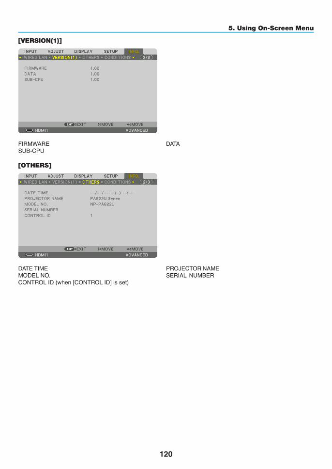
120
5. Using On-Screen Menu
[VERSION(1)]
FIRMWARE DATASUB-CPU
[OTHERS]
DATETIME PROJECTORNAMEMODELNO. SERIALNUMBERCONTROLID(when[CONTROLID]isset)

121
5. Using On-Screen Menu
[CONDITIONS]
INTAKETEMPERATURE EXHAUSTTEMPERATUREINSTALLATIONPOSITION X-AXISY-AXIS Z-AXIS
AbouttheX-AXIS,Y-AXISandZ-AXISCONDITIONS* ArrowdirectionoftheZ-AXISinthefigurerepresentsthetopoftheprojector.
X-AXIS ������������������� Display the projector image at an angle of −100 – +100 degrees to the horizontal in the X-axis direction�
X-AXISvalueof theprojector
HorizontalplaneX-axis
Gravitydirection
Y-AXIS ������������������� Display the projector image at an angle of −100 – +100 degrees to the horizontal in the Y-axis direction�
Y-AXISvalueof theprojector
HorizontalplaneY-axis Gravitydirection
Z-AXIS ������������������� Display the projector image at an angle of −100 – +100 degrees to the vertical in the Z-axis direction�
Z-AXISvalueof theprojector
HorizontalplaneZ-axis
Gravitydirection

122
5. Using On-Screen Menu
[HDBaseT]
SIGNALQUALITY OPERATIONMODELINKSTATUS HDMISTATUS

123
❶ Mounting a lens (sold separately)Sixseparatebayonetstylelensescanbeusedwiththisprojector.ThedescriptionsherearefortheNP13ZL(2xzoom)lens.Mountotherlensesinthesamemanner.
NOTE:• Theprojectorandlensesaremadeofprecisionparts.Donotsubjectthemtoshockorexcessiveforces.• Removetheseparatelysoldlenswhenmovingtheprojector.Ifnot,thelenscouldbesubjecttoshockwhiletheprojectorisbeing
moved, damaging the lens and the lens shift mechanism.• Turnoffthepowerandwaitforthecoolingfantostopbeforemountingorremovingthelens.• Nevertouchthelenssurfacewhiletheprojectorisoperating.• Beverycarefulnottoletdirt,grease,etc.,onthelenssurfaceandnottoscratchthelenssurface.• Performtheseoperationsonaflatsurfaceoverapieceofcloth,etc.,topreventthelensfromgettingscratched.• Whenleavingthelensofftheprojectorforlongperiodsoftime,mountthedustcapontheprojectortopreventdustordirtfrom
getting inside.• Ifyouhavemultipleprojectors,becarefulofthefollowing:
- WhenmountingalensdesignedexclusivelyforthisprojectorontoanotherprojectorintheNPseries,besuretoremovethelensattachmentbeforemountingthelensontheprojector.Thelenscannotbemountedifitsattachmentison.Forthetypesoflensesthatcanbemountedandinstructionsonremovingthem,seethelense’soperatinginstructions.
- Other types of lenses cannot be mounted on this projector.
Mounting the lens1. Remove the dust cap from the projector.
2. Remove the lens cap on the back of the lens.
3. Insert the lens onto the projector with the yellow-marked protrusion on the lens facing upwards.
Thereisapositioningslitontheprojector’slensinsertionslot.Insertthelensslowlyallthewayin,keepingthepositioningslitatthesameangle.
Guidingnotch
Yellowmark
6. Connecting to Other Equipment

124
6. Installation and Connections
4. Turn the lens clockwise.
Turnuntilaclickisheard.
Thelensisnowfastenedontotheprojector.
TIP:MountingthelenstheftpreventionscrewFastenthelenstheftpreventionscrewincludedwiththeprojectortothebottom of the projector so that the lens cannot be removed easily.
Removing the lens
1. While pressing the lens release button on the projector’s front panel fully in, turn the lens counterclockwise.
Thelenscomesoff.
NOTE: • Checkthefollowingareasifthelensunitcannotberemovedeven
when the lens release button is pressed.1.Checkwhetherthetheftpreventionscrewsofthelensunithave
been installed.2.Thelensreleasebuttonmaybelockedsometimes.Inthatcase,
turn the lens fully to the right. The lens release button lock will be released.
2. Slowly pull the lens off the projector.
• Afterremovingthelens,mountthelenscaps(frontandback)includedwiththelensbeforestoringthelens.
• Ifnolensisgoingtobemountedontheprojector,mountthedustcapincludedwiththeprojector.

125
6. Installation and Connections
❷ Making ConnectionsAcomputercable,BNCcable(5-coretype),HDMIcable,oraDisplayPortcablecanbeusedtoconnecttoacom-puter.Theconnectioncableisnotenclosedwiththeprojector.Pleasegetreadyasuitablecablefortheconnection.
Analog RGB signal connection
• Connectthecomputercabletothedisplayoutputterminal(miniD-sub15pin)onthecomputerandthecomputervideoinputterminalontheprojector.Pleaseuseacomputercableattachedwithaferritecore.
• Whenconnectingthedisplayoutputterminal(miniD-sub15pin)onthecomputertotheBNCvideoinputterminal,useaconversioncabletoconverttheBNCcable(5core)toaminiD-sub15pincable.
• Selectthesourcenameforitsappropriateinputconnectorafterturningontheprojector.
InputconnectorINPUTbuttonontheprojector
cabinetButtonontheremotecontrol
COMPUTERIN 7:COMPUTER 7/COMPUTER
BNCIN 4:BNC 4/BNC
COMPUTER IN
BNC IN
AUDIO IN
AUDIO IN
Computercable(soldcommercially)
Stereomini-plugaudiocable(notsupplied)
RGB-to-BNCcable(notsupplied)
Stereomini-plugaudiocable(notsupplied)
NOTE: Please check the operating manual of the computer as the name, position and direc-tion of the terminal may differ depending on the computer.
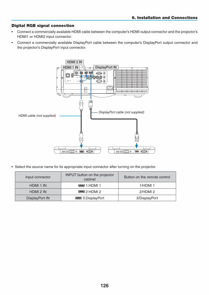
126
6. Installation and Connections
Digital RGB signal connection
• ConnectacommerciallyavailableHDMIcablebetweenthecomputer’sHDMIoutputconnectorandtheprojector’sHDMI1orHDMI2inputconnector.
• ConnectacommerciallyavailableDisplayPortcablebetweenthecomputer’sDisplayPortoutputconnectorandtheprojector’sDisplayPortinputconnector.
• Selectthesourcenameforitsappropriateinputconnectorafterturningontheprojector.
InputconnectorINPUTbuttonontheprojector
cabinetButtonontheremotecontrol
HDMI1IN 1:HDMI1 1/HDMI1
HDMI2IN 2:HDMI2 2/HDMI2
DisplayPortIN 3:DisplayPort 3/DisplayPort
DisplayPort INHDMI 1 IN
HDMI 2 IN
HDMIcable(notsupplied)DisplayPortcable(notsupplied)

127
6. Installation and Connections
Cautions when connecting an HDMI cable• UseacertifiedHighSpeedHDMI®CableorHighSpeedHDMI®CablewithEthernet.
CautionswhenconnectingaDisplayPortcable• UseacertifiedDisplayPortcable.
• Dependingonthecomputer,sometimemayberequireduntiltheimageisdisplayed.
• SomeDisplayPortcables(commerciallyavailable)havelocks.
• Todisconnectthecable,pressthebuttononthetopofthecable’sconnector,thenpullthecableout.
• PowercanbesuppliedtotheconnectingdevicefromtheDisplayPortinputterminal(maximumof1.65W).How-ever,powerwillnotbesuppliedtothecomputer.
• WhensignalsfromadevicethatusesasignalconverteradapterareconnectedtotheDisplayPortinputconnector,insomecasestheimagemaynotbedisplayed.
• WhentheHDMIoutputofacomputerisconnectedtotheDisplayPortinputconnector,useaconverter(commer-ciallyavailable).

128
6. Installation and Connections
CautionswhenusingaDVIsignal• WhenthecomputerhasaDVIoutputconnector,useacommerciallyavailableconvertercabletoconnect thecomputertotheprojector’sHDMI1orHDMI2inputconnector(onlydigitalvideosignalscanbeinput).Also,con-nectthecomputer’saudiooutputtotheprojector’sBNCaudioinputconnector.Inthiscase,switchtheHDMI1orHDMI2settingaton-screenmenu’saudioselectionontheprojectorto[BNC].(→page112)
Toconnectthecomputer’sDVIoutputconnectortotheprojector’sDisplayPortinputconnector,useacommerciallyavailableconverter.
HDMI 1 INHDMI 2 IN
AUDIO IN
NOTE:WhenViewingaDVIDigitalSignal• Turnoffthepowerofthecomputerandprojectorbeforeconnecting.• Lowerthecomputer’svolumesettingbeforeconnectinganaudiocabletotheheadphonesconnector.Whenusingwithacomputer
connected to the projector, adjust the volume of both the projector and computer to set the appropriate volume level.• Ifthecomputerhasamini-jacktypeaudiooutputconnector,werecommendconnectingtheaudiocabletothatconnector.• Whenavideodeckisconnectedviaascanconverter,etc.,thedisplaymaynotbecorrectduringfast-forwardingandrewind-
ing.• UseaDVI-to-HDMIcablecompliantwithDDWG(DigitalDisplayWorkingGroup)DVI(DigitalVisualInterface)revision1.0stan-
dard.Thecableshouldbewithin197"/5mlong.• TurnofftheprojectorandthePCbeforeconnectingtheDVI-to-HDMIcable.• ToprojectaDVIdigitalsignal:Connectthecables,turntheprojectoron,thenselecttheHDMIinput.Finally,turnonyourPC. Failuretodosomaynotactivatethedigitaloutputofthegraphicscardresultinginnopicturebeingdisplayed.Shouldthishappen,
restartyourPC.• SomegraphicscardshavebothanalogRGB(15-pinD-Sub)andDVI(orDFP)outputs.Useofthe15-pinD-Subconnectormay
result in no picture being displayed from the digital output of the graphics card.• DonotdisconnecttheDVI-to-HDMIcablewhiletheprojector isrunning.If thesignalcablehasbeendisconnectedandthen
reconnected,animagemaynotbecorrectlydisplayed.Shouldthishappen,restartyourPC.• TheCOMPUTERvideoinputconnectorssupportWindowsPlugandPlay.TheBNCvideoinputconnectordoesnotsupportWin-
dows Plug and Play.• AMacsignaladapter(commerciallyavailable)mayberequiredtoconnectaMaccomputer. ToconnectaMaccomputerequippedwithaMiniDisplayPorttotheprojector,useacommerciallyavailableMiniDisplayPort→
DisplayPortconvertercable.
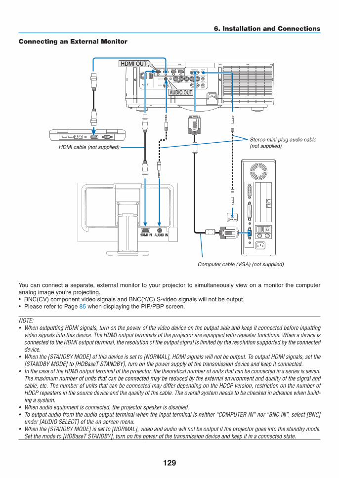
129
6. Installation and Connections
HDMI IN AUDIO IN
HDMI OUT
AUDIO OUT
Connecting an External Monitor
Youcanconnectaseparate,externalmonitortoyourprojectortosimultaneouslyviewonamonitorthecomputeranalogimageyou’reprojecting.• BNC(CV)componentvideosignalsandBNC(Y/C)S-videosignalswillnotbeoutput.• PleaserefertoPage85whendisplayingthePIP/PBPscreen.
NOTE:• WhenoutputtingHDMIsignals,turnonthepowerofthevideodeviceontheoutputsideandkeepitconnectedbeforeinputting
videosignalsintothisdevice.TheHDMIoutputterminalsoftheprojectorareequippedwithrepeaterfunctions.WhenadeviceisconnectedtotheHDMIoutputterminal,theresolutionoftheoutputsignalislimitedbytheresolutionsupportedbytheconnecteddevice.
• Whenthe[STANDBYMODE]ofthisdeviceissetto[NORMAL],HDMIsignalswillnotbeoutput.TooutputHDMIsignals,setthe[STANDBYMODE]to[HDBaseTSTANDBY],turnonthepowersupplyofthetransmissiondeviceandkeepitconnected.
• InthecaseoftheHDMIoutputterminaloftheprojector,thetheoreticalnumberofunitsthatcanbeconnectedinaseriesisseven.The maximum number of units that can be connected may be reduced by the external environment and quality of the signal and cable,etc.ThenumberofunitsthatcanbeconnectedmaydifferdependingontheHDCPversion,restrictiononthenumberofHDCPrepeatersinthesourcedeviceandthequalityofthecable.Theoverallsystemneedstobecheckedinadvancewhenbuild-ing a system.
• Whenaudioequipmentisconnected,theprojectorspeakerisdisabled.• Tooutputaudiofromtheaudiooutputterminalwhentheinputterminalisneither“COMPUTERIN”nor“BNCIN”,select[BNC]
under[AUDIOSELECT]oftheon-screenmenu.• Whenthe[STANDBYMODE]issetto[NORMAL],videoandaudiowillnotbeoutputiftheprojectorgoesintothestandbymode.
Setthemodeto[HDBaseTSTANDBY],turnonthepowerofthetransmissiondeviceandkeepitinaconnectedstate.
Computercable(VGA)(notsupplied)
Stereomini-plugaudiocable(notsupplied)HDMIcable(notsupplied)

130
6. Installation and Connections
Connecting Your Blu-ray Player or Other AV EquipmentComponentvideosignal/S-videosignalconnection
• Selectthesourcenameforitsappropriateinputconnectorafterturningontheprojector.
InputconnectorINPUTbuttonontheprojector
cabinetButtonontheremotecontrol
BNC(CV)IN 5:BNC(CV) 5/BNC(CV)
BNC(Y/C)IN 6:BNC(Y/C) 6/BNC(Y/C)
NOTE:• TheBNC(analogRGB/component),BNC(CV)andBNC(Y/C)audioinputterminalsareshared.
CV Y C
BNC(C) IN
AUDIO INBNC(CV) IN
BNC(Y) IN
Audiocable(notsupplied)BNCcable(notsupplied)
Audioequipment
Audiocable(notsupplied)

131
6. Installation and Connections
Connecting Component Input
• Selectthesourcenameforitsappropriateinputconnectorafterturningontheprojector.
InputconnectorINPUTbuttonontheprojector
cabinetButtonontheremotecontrol
COMPUTERIN 7:COMPUTER 7/COMPUTER
BNCIN 4:BNC 4/BNC
NOTE:• Whenthesignalformatissetto[AUTO](defaultfactorysettingwhenshipped),thecomputersignalandcomponentsignalare
automatically distinguished and switched. If the signals cannot bedistinguished, select [COMPONENT]under [ADJUST]→ [VIDEO]→[SIGNALTYPE]intheon-screenmenuoftheprojector.
• ToconnecttoavideodevicewithaDconnector,usethesoldseparatelyDconnectorconverteradapter(modelADP-DT1E).
AUDIO INCOMPUTER IN
AUDIO IN
15-pin-to-RCA(female)×3cableadapter(ADP-CV1E) BNC(male)-to-RCA(male)conversioncable×3
(soldcommercially)
Stereominiplug-to-RCAaudiocable(notsupplied)
ComponentvideoRCA×3cable(notsupplied)
Blu-rayplayer AudioEquipment

132
6. Installation and Connections
Connecting HDMI InputYoucanconnecttheHDMIoutputofyourBlu-rayplayer,harddiskplayer,ornotebooktypePCtotheHDMI1INorHDMI2INconnectorofyourprojector.
InputconnectorINPUTbuttonontheprojector
cabinetButtonontheremotecontrol
HDMI1IN 1:HDMI1 1/HDMI1
HDMI2IN 2:HDMI2 2/HDMI2
TIP:ForusersofaudiovideoequipmentwithanHDMIconnector:Select“Enhanced”ratherthan“Normal”ifHDMIoutputisswitchablebetween“Enhanced”and“Normal”.This will provide improved image contrast and more detailed dark areas.Formoreinformationonsettings,refertotheinstructionmanualoftheaudiovideoequipmenttobeconnected.
• WhenconnectingtheHDMI1INorHDMI2INconnectoroftheprojectortotheBlu-rayplayer,theprojector’svideolevelcanbemadesettingsinaccordancewiththeBlu-rayplayer’svideolevel.Inthemenuselect[ADJUST]→ [VIDEO]→[VIDEOLEVEL]andmakenecessarysettings.
• IftheHDMIinputsoundcannotbeheard,inthemenuselect[AUDIOSELECT]→[HDMI1]or[HDMI2].
• If theHDMI input’ssound isnotoutput,check that [SOURCEOPTIONS]→ [AUDIOSELECT]→ [HDMI1]or[HDMI2]ontheprojector’son-screenmenuissetto“HDMI”.(→page112)
HDMI 1 IN HDMI 2 IN
Audiocable(notsupplied)
HDMIcable(notsupplied)UseHighSpeedHDMI® Cable.

133
6. Installation and Connections
Connecting to a HDBaseT transmission device (sold commercially)HDBaseTisaconnectionstandardforhomeappliancesthatisestablishedbytheHDBaseTAlliance.UseaLANcablesoldcommerciallytoconnecttheEthernet/HDBaseTportoftheprojector(RJ-45)toaHDBaseTtransmissiondevicesoldcommercially.TheEthernet/HDBaseTportoftheprojectorsupportsHDMIsignals(HDCP)fromtransmissiondevices,controlsignalsfromexternaldevices(serial,LAN)andremotecontrolsignals(IRcommands).
Connection example
Ethernet/HDBaseT
Computer(forcontroluse)Computer(foroutputuse)
Exampleofatransmissiondevice
Ourcompany’sremotecontrol(PX750U/PH1000U/PH1400USeries)
HDMIoutputvideodevice
NOTE:• Pleaseuseashieldedtwistedpair(STP)cableofCategory5eorhigherfortheLANcable(soldcommercially).• ThemaximumtransmissiondistanceovertheLANcableis100m.(themaximumdistanceis70mfora4Ksignal)• Pleasedonotuseothertransmissionequipmentbetweentheprojectorandtransmissionequipment.Thepicturequalitymaybe
degraded as a result.• ThisprojectorisnotguaranteedtoworkwithallHDBaseTtransmissiondevicessoldcommercially.

134
6. Installation and Connections
Portrait projection (vertical orientation)Portraitscreensfromacomputercanbeprojectedbyinstallingtheprojec-torinaverticalorientation.Allthescreenssuchastheon-screenmenuwillberotatedinancounter-clockwisedirection.
Theprojectorisequippedwithasensortoautomaticallydetecttheinstal-lationstate.Whentheprojectorisinstalledinaportraitconfigurationforthefirsttimewiththelamplitup,acautionmessagetoindicatethattheoperatingtimeofthelampmaybeshortenedwillbedisplayed.Thismessagewillautomaticallydisappearwhentheinstallationstateoftheprojectorisreturnedtotheoriginalstate.
Precautions during installation• Pleasedonotinstalltheprojectorinaverticalorientationontopofthefloorortableonitsown.Theairinletmaybeobstructed,resultingintheprojectorgettingwarmandthepossibilityoffireandmalfunctionoccurring.
• Forverticalinstallation,installtheprojectorwiththeairinlet(filter)facingdownwards.Astandforsupportingtheprojectorneedstobemadeforthispurpose.Inthiscase,thestandmustbedesignedsuchthatthecenterofgravityoftheprojectorislocatedwellwithinthelegsofthestand.Ifnot,theprojectormayfalloverandresultininjury,damageandmalfunction.
• Donotusethelensshiftfunctionwhenperformingportraitprojection.Usethepositionofthelensshiftmecha-nisminthecenter(lenscenter).
NOTE:• Thelampreplacementtime(asaguide)*isabout2000hoursforportraitprojection.
* Replacementtimeisnotguaranteed.• Wheninstallinginaportraitconfigurationforthefirsttime,portraitprojectioncannotbeusedwhenthenumberoflamphours
usedshownunder[INFO.]→[USAGETIME]→[LAMPHOURSUSED]intheon-screenmenuexceeds1900hours.• Whenthe[FANMODE]issettoamodeotherthan[AUTO],portraitprojectioncannotbeused.
Design and manufacturing conditions for the standPleaseengageaninstallationserviceproviderforthedesignandmanufactureofthecustomizedstandtobeusedforportraitprojection.Pleaseensurethatthefollowingarecompliedwithwhendesigningthestand.1. Maintainanopeningofatleast310×170mmsoasnottoobstructtheairinlet/filteroftheprojector.
2. Maintainadistanceofatleast130mmbetweentheprojectorairinletandthefloor(fortheopeningofthefiltercover).
3. Usethefourscrewholesatthebackoftheprojectortosecureittothestand.
Screwholecenterdimension:200×250mm
Screwholedimensionontheprojector:M4withamaximumdepthof8mm.
* Pleasedesignthestandsuchthattherearlegsatthebackoftheprojectordonotcontactthestand.Thefrontlegscanbeturnedandremoved.
4. Horizontaladjustmentmechanism(forexample,boltsandnutsinfourlocations)
5. Pleasedesignthestandsuchthatitdoesnottoppleovereasily.

135
6. Installation and Connections
Reference drawings* Thedrawingshowingthedimensionalrequirementsisnotanactualstanddesigndrawing.
[Side View] [Front View]
Screw holes for 4 - M4 use
Tilt foot (remove)
130 or greater
200
Filter cover (when opened)
Horizontal adjuster
[Bottom View]
Filter cover
310 or greater
Rear foot
Lens shift securing method
1. Pull the securing lever cover towards you to remove it.
• Thecovercannotbedetachedfromtheprojector.
2. Turn the screws to the left to loosen them.
• Screwscannotberemoved.
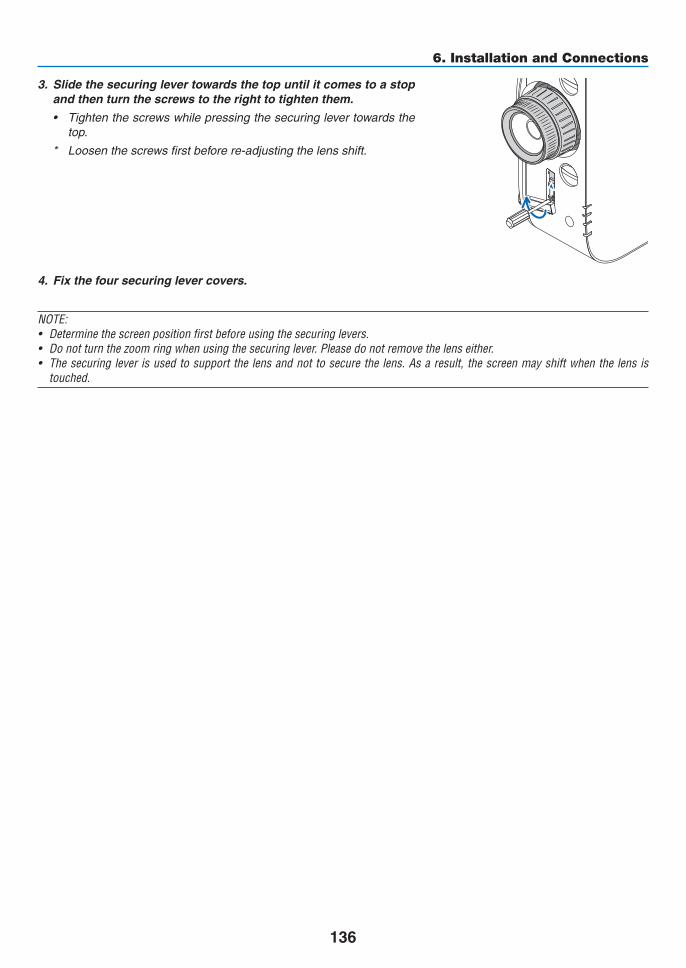
136
6. Installation and Connections
3. Slide the securing lever towards the top until it comes to a stop and then turn the screws to the right to tighten them.
• Tightenthescrewswhilepressingthesecuringlevertowardsthetop.
* Loosenthescrewsfirstbeforere-adjustingthelensshift.
4. Fix the four securing lever covers.
NOTE:• Determinethescreenpositionfirstbeforeusingthesecuringlevers.• Donotturnthezoomringwhenusingthesecuringlever.Pleasedonotremovethelenseither.• Thesecuringleverisusedtosupportthelensandnottosecurethelens.Asaresult,thescreenmayshiftwhenthelensis
touched.

137
6. Installation and Connections
Connecting to a Wired LANTheprojectorcomesstandardwithaEthernet/HDBaseTport(RJ-45)whichprovidesaLANconnectionusingaLANcable.TouseaLANconnection,youarerequiredtosettheLANontheprojectormenu.Select[SETUP]→[NETWORKSETTINGS]→[WIREDLAN].(→page107).
Example of LAN connectionExampleofwiredLANconnection
Server
Hub
LANcable(notsupplied)
NOTE: Use a Category 5 or higher LANcable.

138
7. MaintenanceThissectiondescribesthesimplemaintenanceproceduresyoushouldfollowtocleanthefilters,thelens,thecabinet,andtoreplacethelampandthefilters.
❶ Cleaning the FiltersTheair-filterspongekeepsdustanddirtfromgettinginsidetheprojectorandshouldbefrequentlycleaned.Ifthefilterisdirtyorclogged,yourprojectormayoverheat.
WARNING• Pleasedonotuseaspraycontainingflammablegastoremovedustattachedtothefilters,etc.Doingsomayresultinfires.
NOTE:Themessageforfiltercleaningwillbedisplayedforoneminuteaftertheprojectoristurnedonoroff.Whenthemessageisdisplayed,cleanthefilters.Thetimetocleanthefiltersissetto[OFF]attimeofshipment.(→ page 95)To cancel the message, press any button on the projector cabinet or the remote control.
The two-layerfilteron theprojector improvescoolinganddust-proofcapabilitiescomparedwith theconventionalmodels.Theoutsides(intakeside)ofthefirstandsecondlayerfiltersremovedust.Tocleanthefilter,detachthefilterunitandthefiltercover.
CAUTION• Beforecleaningthefilters,turnofftheprojector,disconnectthepowercordandthenallowthecabinettocool.Failuretodosocanresultinelectricshockorburninjuries.
1. Press down on the buttons on the left and right and then pull the filter cover towards you to open it.
Thecoverwillopenabout90degreesbeforeitstops.
Filtercover Button
When mounting the projector to a ceiling
Thefiltercoverwillopenabout90degreesbeforeitcomestoastopatthestopperposition.Removeyourhandsasthestopperwillbedetachedifitisopenedfurther.Thefiltercoverwillstopatapositionofabout90degrees.
However,thefiltercovermaycloseiftheprojectorvibrates.

139
7. Maintenance
2. Remove the filter unit by pulling out the tab.
Filterunit Tab
3. Remove the four filters.
Holdandremovethefiltersfittedtothetwosidesofthefilterunit.
4. Use a vacuum cleaner to vacuum all the dust inside.
Getridofdustinthefilter.
NOTE: • Wheneveryouvacuumthefilter,usethesoftbrushattachmentto
vacuum.Thisistoavoiddamagetothefilter.• Donotwashthefilterwithwater.Doingsocanresultinfilterclog-
ging.
5. Remove the dust on the front and back of the filter unit.
• Pleasealsoremovealldustfromthefiltercoverofthepro-jector.

140
7. Maintenance
6. Attach 4 new filters to both sides of the filter unit.
The installation locations of the filters are differentiated bywhetherthereareanyslits(notches).Installthefilterundertheflangearoundthefilterunitasfollows.
(1)Attachthe2filterswithtransparentframesfittedtothegripstothesideofthefilterunitwheretheknobislocated.
• Turnoverthesideofthefilterwiththetransparentboxandtheninstallit.
(2)Attachthe2filterswiththeblacklinestothesideofthefilterunitwherethereisnoknob.
• Turnover thesideof thefilterwith theblack line,andtheninserttheslitsintotheprotrusionsonthefilterunittoinstallit.
Flange
Knob
Slit
7. Mount the filter unit back onto the projector cabinet.
Insertthefilterunitontotheprojectorwiththesidesonwhichtheleftandrighthooksarelocatedontheoutside.
Hook
8. Closethefiltercover.
Afterclosing,pushthefiltercovernearthebuttonsuntila“click”soundisheard.Thefiltercoverwillbesecuredinposition.
Button
9. Clearthefilterusagehours.
Plugthepowercordintothewalloutlet,andthenturnontheprojector.
Fromthemenu,select[RESET]→[CLEARFILTERHOURS].(→page117)
Theintervaltimetocleanthefiltersissetto[OFF]attimeofshipment.Whenusingtheprojectorasitis,youdonotclearthefilterusage

141
7. Maintenance
❷ Cleaning the Lens• Turnofftheprojectorbeforecleaning.
• Theprojectorhasaplasticlens.Useacommerciallyavailableplasticlenscleaner.
• Donotscratchormarthelenssurfaceasaplasticlensiseasilyscratched.
• Neverusealcoholorglasslenscleanerasdoingsowillcausedamagetotheplasticlenssurface.
WARNING• Pleasedonotuseaspraycontainingflammablegastoremovedustattachedtothelens,etc.Doingsomayresultinfires.
❸ Cleaning the CabinetTurnofftheprojector,andunplugtheprojectorbeforecleaning.• Useadrysoftclothtowipedustoffthecabinet.
Ifheavilysoiled,useamilddetergent.
• Neverusestrongdetergentsorsolventssuchasalcoholorthinner.
• Whencleaningtheventilationslitsorthespeakerusingavacuumcleaner,donotforcethebrushofthevacuumcleanerintotheslitsofthecabinet.
Vacuumthedustofftheventilationslits.
• Cloggedventilationslitsmaycauseariseintheinternaltemperatureoftheprojector,resultinginmalfunction.
• Donotscratchorhitthecabinetwithyourfingersoranyhardobjects
• Contactyourdealerforcleaningtheinsideoftheprojector.
NOTE:Donotapplyvolatileagentsuchasinsecticideonthecabinet,thelens,orthescreen.Donotleavearubberorvinylproductinprolongedcontactwithit.Otherwisethesurfacefinishwillbedeterioratedorthecoatingmaybestrippedoff.

142
7. Maintenance
❹ Replacing the Lamp and the FiltersWhenthelampreachestheendofitslife,theLAMPindicatorinthecabinetwillblinkredandthemessage“THELAMPHASREACHEDTHEENDOFITSUSABLELIFE.PLEASEREPLACETHELAMPANDFILTER.USETHESPECIFIEDLAMPFORSAFETYANDPERFORMANCE.”willappear(*).Eventhoughthelampmaystillbeworking,replacethelamptomaintaintheoptimalprojectorperformance.Afterreplacingthelamp,besuretoclearthelamphourmeter.(→page116)
CAUTION• DONOTTOUCHTHELAMPimmediatelyafterithasbeenused.Itwillbeextremelyhot.Turntheprojectoroffandthendisconnectthepowercord.Allowatleastonehourforthelamptocoolbeforehandling.
• Usethespecifiedlampforsafetyandperformance.
• DONOTREMOVEANYSCREWSexceptonelampcoverscrewandtwolamphousingscrews.Youcouldreceiveanelectricshock.
• Donotbreaktheglassonthelamphousing.
Keepfingerprintsofftheglasssurfaceonthelamphousing.Leavingfingerprintsontheglasssurfacemightcauseanunwantedshadowandpoorpicturequality.
• Theprojectorwillturnoffandgointostandbymodewhenyoucontinuetousetheprojectorforanother100hoursafterthelamphasreachedtheendofitslife.Ifthishappens,besuretoreplacethelamp.Ifyoucontinuetousethelampafterthelampreachestheendofitslife,thelampbulbmayshatter,andpiecesofglassmaybescatteredinthelampcase.Donottouchthemasthepiecesofglassmaycauseinjury.Ifthishappens,contactyourNECdealerforlampreplacement.
*NOTE: This message will be displayed under the following conditions:• foroneminuteaftertheprojectorhasbeenpoweredon• whenthe (POWER)buttonontheprojectorcabinetortheSTANDBYbuttonontheremotecontrolispressed
To turn off the message, press any button on the projector cabinet or the remote control.
Optionallampandtoolsneededforreplacement:
• Phillipsscrewdriver(plus-head)
• Replacementlamp: NP26LP
Flow of Replacing the Lamp and the Filters
Step 1. Replace the lamp
Step 2. Replace the filters (→ page 145)
Step 3. Clearthelampusagehoursandthefilterusagehours(→ page 116, 117)

143
7. Maintenance
To replace the lamp: 1. Remove the lamp cover.
(1)Loosenthelampcoverscrew
• Thelampcoverscrewisnotremovable.
(2)Pullthebottomofthelampcovertowardsyouandremoveit.
2. Remove the lamp housing.
(1)Loosenthetwoscrewssecuringthelamphousinguntilthephillipsscrewdrivergoesintoafreewheelingcondi-tion.
• Thetwoscrewsarenotremovable.
• Thereisaninterlockonthiscasetopreventtheriskofelectricalshock.Donotattempttocircumventthisinterlock.
(2)Removethelamphousingbyholdingit.
CAUTION:Makesurethatthelamphousingiscoolenoughtobeforeremovingit.
Interlock Guidehole

144
7. Maintenance
3. Install a new lamp housing.
(1)Insertanewlamphousinguntilthelamphousingispluggedintothesocket.
(2)Positionsothattheguideholeinthebottomrightofthelamphouseisovertheprotrusionontheprojectorthenpressallthewayin.
(3)Secureitinplacewiththetwoscrews.
• Besuretotightenthescrews.
4. Reattach the lamp cover.
(1)Insertthetopedgeofthelampcoverintothegrooveintheprojectorandclosethelampcover.
(2)Tightenthescrewtosecurethelampcover.
• Besuretotightenthescrew.
This completes the lamp replacement.Goontothefilterreplacement.
NOTE: • Whenyoucontinuetousetheprojectorforanother100hoursafterthelamphasreachedtheendofitslife,theprojectorcannot
turnonandthemenuisnotdisplayed.Ifthishappens,presstheHELPbuttonontheremotecontrolfor10secondstoresetthelampclockbacktozero.Whenthelamptimeclockisresettozero,theLAMPindicatorgoesout.
• Forportraitprojection,thepowersupplywillbeswitchedoffwhenthelampreplacementtime(estimated)*isreached.Alampreplacement message will be displayed 100 hours before the lamp replacement time is reached.* The replacement time is not guaranteed.

145
7. Maintenance
Toreplacethefilters:Fourfiltersarepackagedwiththereplacementlamp.Honeycombfilter(coarsemesh):Largeandsmallsizes(attachedtotheoutsideofthefilterunit)Accordionfilter(finemesh):Largeandsmallsizes(attachedtotheinsideofthefilterunit)
NOTE: • Replaceallfourfiltersatthesametime.• Beforereplacingthefilters,wipeoffdustanddirtfromtheprojectorcabinet.• Theprojectorisprecisionequipment.Keepoutdustanddirtduringfilterreplacement.• Donotwashthefilterswithsoapandwater.Soapandwaterwilldamagethefiltermembrane.• Putfiltersintoplace.Incorrectattachmentofafiltermaycausedustanddirttogetintotheinsideoftheprojector.
Beforereplacingthefilters,replacethelamp.(→page143)
1. Press down on the buttons on the left and right and then pull the filter cover towards you to open it.
Thecoverwillopenabout90degreesbeforeitstops.
When mounting the projector to a ceiling
Thefiltercoverwillopenabout90degreesbeforeitcomestoastopatthestopperposition.Removeyourhandsasthestopperwillbedetachedifitisopenedfurther.Thefiltercoverwillstopatapositionofabout90degrees.
However,thefiltercovermaycloseiftheprojectorvibrates.
Filtercover Button
2. Remove the filter unit by pulling out the tab.
Filterunit Tab

146
7. Maintenance
3. Remove the four filters.
Holdontothefiltersfittedtobothsidesofthefilterunittoremovethefilterunit.
4. Remove dust from the filter unit and the filter cover.
Cleanbothoutsideandinside.
5. Attach 4 new filters to both sides of the filter unit.
Theinstallationlocationsofthefiltersaredifferentiatedbywhetherthereareanyslits(notches).Installthefilterundertheflangearoundthefilterunitasfollows.
(1)Attachthe2filterswithtransparentframesfittedtothegripstothesideofthefilterunitwheretheknobislo-cated.
• Turnoverthesideofthefilterwiththetransparentboxandtheninstallit.
(2)Attachthe2filterswiththeblacklinestothesideofthefilterunitwherethereisnoknob.
• Turnoverthesideofthefilterwiththeblackline,andtheninserttheslitsintotheprotrusionsonthefilterunittoinstallit.
6. Mount the filter unit back onto the projector cabinet.
Insertthefilterunitontotheprojectorwiththesidesonwhichtheleftandrighthooksarelocatedontheoutside.
7. Closethefiltercover.
Afterclosing,pushthefiltercovernearthebuttonsuntila“click”soundisheard.Thefiltercoverwillbesecuredinposition.
Thiscompletesthefilterreplacement.Goontotheclearinglampandfilterhourmeters.
Toclearthelampusagehoursandthefilterusagehours:1. Place the projector where you use it.
2. Plug the power cord into the wall outlet, and then turn on the projector.
3. Clearthelampusagehoursandthefilterusagehours.
1. Fromthemenu,select[RESET]→[CLEARLAMPHOURS]andresetthelampusagehours.
2. Select[CLEARFILTERHOURS]andresetthefilterusagehours.(→page117)

147
8. User Supportware❶ Operating Environment for Software Included on CD-ROMNames and Features of Bundled Software Programs
Nameofsoftwareprogram Features
VirtualRemoteTool(Windowsonly)
Whenthecomputerandprojectorareconnectedusinganetwork(wiredLAN),suchoperationsasturningtheprojector’spoweronandoffandswitchingthesignalcanbeperformed.Itisalsopossibletosendanimagetotheprojectorandregisteritasthebackgroundlogo.Oncetheimageisregistered,itcanbelockedtopreventthelogofrombeingoverwritten.
PCControlUtilityPro4PCControlUtilityPro5(forMacOS)
ThisisasoftwareprogramusedtooperatetheprojectorfromthecomputerwhenthecomputerandtheprojectorareconnectedwithLAN.(→page137)• PCControlUtilityPro4canbeusedwithaserialconnection.
* ThefollowingthreesoftwareontheCD-ROMcannotbeusedinthisdevice. ImageExpressUtilityLite(forWindows/MacOS),ImageExpressUtility2.0(forWindows)andDesktopControlUtility1.0(forWindows)
Download serviceFortheupdateinformationaboutthesesoftwareprograms,visitourwebsite:URL:http://www.nec-display.com/dl/en/index.html
Operating EnvironmentThefollowingistheoperatingenvironmentforImageExpressUtilityLite.Fortheoperatingenvironmentofothersoft-wareprogram,refertothehelpfunctionofeachsoftwareprogram.
[Windows]
SupportedOS Windows8(CoreEdition)Windows8ProWindows8EnterpriseWindows7HomeBasicWindows7HomePremiumWindows7ProfessionalWindows7UltimateWindows7EnterpriseWindowsVistaHomeBasicWindowsVistaHomePremiumWindowsVistaBusinessWindowsVistaUltimateWindowsVistaEnterpriseWindowsXPHomeEdition(32-bitversion)ServicePack3orlaterWindowsXPProfessional(32-bitversion)ServicePack3orlater• Windowspower-savingfunctionisnotsupported.• Tousetheaudiotransfercapability,Windows8/Windows7/WindowsVistaServicePack1orlaterisrequired.
[Mac]
SupportedOS MacOSXv10.6,v10.7,v10.8
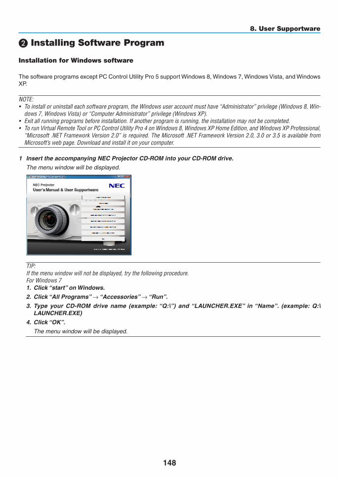
148
8. User Supportware
❷ Installing Software Program
Installation for Windows software
ThesoftwareprogramsexceptPCControlUtilityPro5supportWindows8,Windows7,WindowsVista,andWindowsXP.
NOTE:• Toinstalloruninstalleachsoftwareprogram,theWindowsuseraccountmusthave“Administrator”privilege(Windows8,Win-
dows7,WindowsVista)or“ComputerAdministrator”privilege(WindowsXP).• Exitallrunningprogramsbeforeinstallation.Ifanotherprogramisrunning,theinstallationmaynotbecompleted.• TorunVirtualRemoteToolorPCControlUtilityPro4onWindows8,WindowsXPHomeEdition,andWindowsXPProfessional,
“Microsoft.NETFrameworkVersion2.0”isrequired.TheMicrosoft.NETFrameworkVersion2.0,3.0or3.5isavailablefromMicrosoft’swebpage.Downloadandinstallitonyourcomputer.
1 InserttheaccompanyingNECProjectorCD-ROMintoyourCD-ROMdrive.
Themenuwindowwillbedisplayed.
TIP:If the menu window will not be displayed, try the following procedure.ForWindows71. Click“start”onWindows.
2. Click“AllPrograms”→ “Accessories” → “Run”.
3. Type your CD-ROM drive name (example:“Q:\”) and“LAUNCHER.EXE” in“Name”. (example: Q:\LAUNCHER.EXE)
4. Click“OK”.
Themenuwindowwillbedisplayed.

149
8. User Supportware
2 Clickasoftwareprogramyouwishtoinstallonthemenuwindow.
Theinstallationwillstart.
• Followtheinstructionsontheinstallerscreenstocompletetheinstallation.
TIP:
Uninstalling a Software ProgramPreparation:Exit thesoftwareprogrambeforeuninstalling.Touninstall thesoftwareprogram, theWindowsuseraccountmusthave“Administrator”privilege(Windows8,Windows7,andWindowsVista)or“ComputerAdministrator”privilege(WindowsXP).
•ForWindows8/Windows7/WindowsVista1 Click“Start”andthen“ControlPanel”.
TheControlPanelwindowwillbedisplayed.
2 Click“Uninstallaprogram”under“Programs”
The“ProgramsandFeatures”windowwillbedisplayed.
3 Select the software program and click it.
4 Click“Uninstall/Change”or“Uninstall”.
•Whenthe“UserAccountControl”windowsisdisplayed,click“Continue”.
Followtheinstructionsonthescreenstocompletetheuninstallation.
•ForWindowsXP1 Click“Start”andthen“ControlPanel”.
TheControlPanelwindowwillbedisplayed.
2 Double-click “Add / Remove Programs”.
TheAdd/RemoveProgramswindowwillbedisplayed.
3 Clickthesoftwareprogramfromthelistandthenclick“Remove”.
Followtheinstructionsonthescreenstocompletetheuninstallation.

150
8. User Supportware
Using on Mac OS
Step 1: Install PC Control Utility Pro 5 on the computer.
1. InserttheaccompanyingNECProjectorCD-ROMinyourMacCD-ROMdrive.
TheCD-ROMiconwillbedisplayedonthedesktop.
2. Double-clicktheCD-ROMicon.
TheCD-ROMwindowwillbedisplayed.
3. Double-click the “Mac OS X” folder.
4. Double-click“PCControlUtility.mpkg”.
Theinstallerwillstart.
5. Click“Next”.
“ENDUSERLICENSEAGREEMENT”screenwillbedisplayed.
6. Read“ENDUSERLICENSEAGREEMENT”andclick“Next”.
Theconfirmationwindowwillbedisplayed
7. Click“Iacceptthetermsinthelicenseagreement”.
Followtheinstructionsontheinstallerscreenstocompletetheinstallation.
TIP:
•Uninstallingasoftwareprogram1. Putthe“PCControlUtilityPro5”foldertotheTrashicon.
2. PuttheconfigurationfileofPCControlUtilityPro5totheTrashicon.
• TheconfigurationfileofPCControlUtilityPro5islocatedin“/Users/<yourusername>/ApplicationData/NECProjectorUserSupportware/PCControlUtilityPro5”.

151
8. User Supportware
❸ Operating the Projector Via the LAN (Virtual Remote Tool)Thiswillhelpyouperformoperationssuchasprojector’spoweronoroffandsignalselectionviaaLANconnection.Itisalsousedtosendanimagetotheprojectorandregisteritasthelogodataoftheprojector.Afterregisteringit,youcanlockthelogotopreventitfromchanging.
Control FunctionsPowerOn/Off,signalselection,picturefreeze,picturemute,audiomute,Logotransfertotheprojector,andremotecontroloperationonyourPC.
VirtualRemotescreen
RemoteControlWindow Toolbar
ThissectionprovidesanoutlineofpreparationforuseofVirtualRemoteTool.ForinformationonhowtouseVirtualRemoteTool,seeHelpofVirtualRemoteTool.(→page153)
NOTE:• Logodata(graphics)thatcanbesenttotheprojectorwithVirtualRemoteToolhasthefollowingrestrictions: (OnlyviaserialorLANconnection)
* Filesize:Within256kilobytes* Imagesize:Withintheresolutionoftheprojector* Fileformat:PNG(Fullcolor)
• Logodata(image)sentusingtheVirtualRemoteToolwillbedisplayedinthecenterwiththesurroundingareainblack.• Toputthedefault“NEClogo”backinthebackgroundlogo,youneedtoregisteritasthebackgroundlogobyusingtheimage
file (PA622U/NP-PA522U: \Logo\necpj_bbwux.png, PA672W/PA572W: \Logo\necpj_bbwx.png, PA722X/NP-PA622X: \Logo\necpj_bb_x.png)includedonthesuppliedNECProjectorCD-ROM.
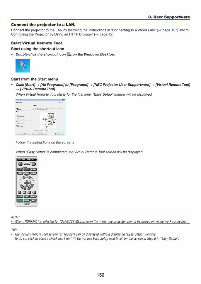
152
8. User Supportware
Connect the projector to a LAN.ConnecttheprojectortotheLANbyfollowingtheinstructionsin“ConnectingtoaWiredLAN”(→page137)and“9.ControllingtheProjectorbyUsinganHTTPBrowser”(→page42)
Start Virtual Remote Tool
Start using the shortcut icon• Double-clicktheshortcuticon on the Windows Desktop.
Start from the Start menu• Click[Start]→[AllPrograms]or[Programs]→[NECProjectorUserSupportware]→[VirtualRemoteTool]
→[VirtualRemoteTool].
WhenVirtualRemoteToolstartsforthefirsttime,“EasySetup”windowwillbedisplayed.
Followtheinstructionsonthescreens
When“EasySetup”iscompleted,theVirtualRemoteToolscreenwillbedisplayed.
NOTE:• When[NORMAL]isselectedfor[STANDBYMODE]fromthemenu,theprojectorcannotbeturnedonvianetworkconnection.
TIP:• TheVirtualRemoteToolscreen(orToolbar)canbedisplayedwithoutdisplaying“EasySetup”window. Todoso,clicktoplaceacheckmarkfor“ DonotuseEasySetupnexttime”onthescreenatStep6in“EasySetup”.
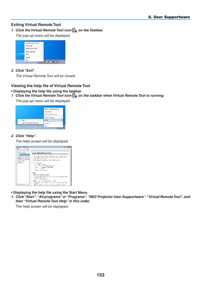
153
8. User Supportware
ExitingVirtualRemoteTool1 ClicktheVirtualRemoteToolicon on the Taskbar.
Thepop-upmenuwillbedisplayed.
2 Click“Exit”.
TheVirtualRemoteToolwillbeclosed.
ViewingthehelpfileofVirtualRemoteTool•Displayingthehelpfileusingthetaskbar1 ClicktheVirtualRemoteToolicon onthetaskbarwhenVirtualRemoteToolisrunning.
Thepop-upmenuwillbedisplayed.
2. Click“Help”.
TheHelpscreenwillbedisplayed.
•DisplayingthehelpfileusingtheStartMenu.1. Click“Start”.“Allprograms”or“Programs”.“NECProjectorUserSupportware”.“VirtualRemoteTool”.and
then“VirtualRemoteToolHelp”inthisorder.
TheHelpscreenwillbedisplayed.

154
8. User Supportware
❹ Controlling the Projector over a LAN (PC Control Utility Pro 4/Pro 5)Usingtheutilitysoftware“PCControlUtilityPro4”or“PCControlUtilityPro5”includedonthecompanionNECPro-jectorCD-ROM,theprojectorcanbecontrolledfromacomputeroveraLAN.PCControlUtilityPro4isaprogramcompatiblewithWindows.(→thispage)PCControlUtilityPro5isaprogramcompatiblewithMacOS.(→page157)
Control FunctionsPowerOn/Off,signalselection,picturefreeze,picturemute,audiomute,adjusting,errormessagenotification,eventschedule.
ScreenofPCControlUtilityPro4
ThissectionprovidesanoutlineofpreparationforuseofPCControlUtilityPro4/Pro5.ForinformationonhowtousePCControlUtilityPro4/Pro5,seeHelpofPCControlUtilityPro4/Pro5.(→page156,157)
Step1:InstallPCControlUtilityPro4/Pro5onthecomputer.Step2:ConnecttheprojectortoaLAN.Step3:StartPCControlUtilityPro4/Pro5.
• TorunPCControlUtilityPro4onWindows8,WindowsXPHomeEditionandWindowsXPProfessional,“Microsoft.NETFramework”isrequired.TheMicrosoft.NETFrameworkVersion2.0,3.0or3.5isavailablefromMicrosoft’swebpage.Downloadandinstalltheitonyourcomputer.
TIP:• PCControlUtilityPro4canbeusedwithaserialconnection.
Using on Windows
Step 1: Install PC Control Utility Pro 4 on the computer
NOTE:• Toinstalloruninstall theprogram,theWindowsuseraccountmusthave[Administrator]privilege(Windows8,Windows7,
WindowsVistaandWindowsXP)• Exitallrunningprogramsbeforeinstallation.Ifanotherprogramisrunning,theinstallationmaynotbecompleted.
1 InserttheaccompanyingNECProjectorCD-ROMintoyourCD-ROMdrive.
Themenuwindowwillbedisplayed.

155
8. User Supportware
TIP:If the menu window will not be displayed, try the following procedure.ForWindows7:1. Click“start”onWindows.
2. Click“AllPrograms”→ “Accessories” → “Run”.
3. Type your CD-ROM drive name (example:“Q:\”) and“LAUNCHER.EXE” in“Name”. (example: Q:\LAUNCHER.EXE)
4. Click“OK”.
themenuwindowwillbedisplayed.
2 Click“PCControlUtilityPro4”onthemenuwindow.
Theinstallationwillstart.
Whentheinstallationiscomplete,theWelcomewindowwillbedisplayed.
3 Click“Next”.
“ENDUSERLICENSEAGREEMENT”screenwillbedisplayed.
Read“ENDUSERLICENSEAGREEMENT”carefully.
4 If you agree, click “I accept the terms in the license agreement” and then click “Next”.
• Followtheinstructionsontheinstallerscreenstocompletetheinstallation.
• Whentheinstallationiscomplete,youwillreturntothemenuwindow.
TIP:•UninstallingPCControlUtilityPro4TouninstallPCControlUtilityPro4,dothesameproceduresstatedasin“UninstallingaSoftwareProgram”.(→ page 149)

156
8. User Supportware
Step 2: Connect the projector to a LAN.ConnecttheprojectortotheLANbyfollowingtheinstructionsin“ConnectingtoaWiredLAN”(→page137)and“9.ControllingtheProjectorbyUsinganHTTPBrowser”(→page42)
Step 3: Start PC Control Utility Pro 4Click“Start”→“Allprograms”or“Programs”→“NECProjectorUserSupportware”→“PCControlUtilityPro4”→ “PCControlUtilityPro4”.
NOTE: • FortheSchedulefunctionofthePCControlutilityPro4towork,youmusthaveyourcomputerrunningandnotinstandby/
sleepmode.Select“PowerOptions”fromthe“ControlPanel”inWindowsanddisableitsstandby/sleepmodebeforerunningthescheduler.
[Example]ForWindows7:Select“ControlPanel”→“SystemandSecurity”→“PowerOptions”→“Changewhenthecomputersleeps”→“Putthecomputertosleep”→“Never”.NOTE: • When[NORMAL]isselectedfor[STANDBYMODE]fromthemenu,theprojectorcannotbeturnedonviathenetwork(wiredLAN)
connection.
TIP:
ViewingtheHelpofPCControlUtilityPro4• DisplayingtheHelpfileofPCControlUtilityPro4whileitisrunning.
Click“Help(H)”→“Help(H)…”ofwindowofPCControlUtilityPro4inthisorder.
Thepop-upmenuwillbedisplayed.
• DisplayingthehelpfileusingtheStartMenu.
Click“Start”→“Allprograms”or“Programs”→“NECProjectorUserSupportware”→“PCControlUtilityPro4”→ “PCControlUtilityPro4Help”.
TheHelpscreenwillbedisplayed.
157
8. User Supportware
Using on Mac OS
Step 1: Install PC Control Utility Pro 5 on the computer1. InserttheaccompanyingNECProjectorCD-ROMinyourMacCD-ROMdrive.
TheCD-ROMiconwillbedisplayedonthedesktop.
2. Double-clicktheCD-ROMicon.
TheCD-ROMwindowwillbedisplayed.
3. Double-click the “Mac OS X” folder.
4. Double-click“PCControlUtility.mpkg”.
Theinstallerwillstart.
5. Click“Next”.
“ENDUSERLICENSEAGREEMENT”screenwillbedisplayed.
6. Read“ENDUSERLICENSEAGREEMENT”andclick“Next”.
Theconfirmationwindowwillbedisplayed
7. Click“Iacceptthetermsinthelicenseagreement”.
Followtheinstructionsontheinstallerscreenstocompletetheinstallation.
Step 2: Connect the projector to a LANConnecttheprojectortotheLANbyfollowingtheinstructionsin“ConnectingtoaWiredLAN”(→page137)and“❾ ControllingtheProjectorbyUsinganHTTPBrowser”(→page42)
Step 3: Start PC Control Utility Pro 51. Open your Applications folder in Mac OS.
2. Clickthe“PCControlUtilityPro5”folder.
3. Clickthe“PCControlUtilityPro5”icon.
PCControlUtilityPro5willstart.
NOTE: • FortheSchedulefunctionofthePCControlutilityPro5towork,youmusthaveyourcomputerrunningandnotinsleepmode.
Select“EnergySaver”fromthe“SystemPreferences”inMacanddisableitssleepmodebeforerunningthescheduler.• When[NORMAL]isselectedfor[STANDBYMODE]fromthemenu,theprojectorcannotbeturnedonviathenetwork(wiredLAN)
connection. TIP:
ViewingtheHelpofPCControlUtilityPro5•DisplayingtheHelpfileofPCControlUtilityPro5whileitisrunning.• Fromthemenubar,click“Help”→“Help”inthisorder.
TheHelpscreenwillbedisplayed.
•DisplayingtheHelpusingtheDock1. Open “Application Folder” in Mac OS.
2. Clickthe“PCControlUtilityPro5”folder.
3. Clickthe“PCControlUtilityPro5Help”icon.
TheHelpscreenwillbedisplayed.

158
9. Appendix
❶ Throw distance and screen sizeSixseparatebayonetstylelensescanbeusedonthisprojector.Refertotheinformationonthispageandusealenssuitedfortheinstallationenvironment(screensizeandthrowdistance).Forinstructionsonmountingthelens,seepage123.
Lens types and throw distancePA722X/PA622X
Screensize LensmodelnameNP11FL NP30ZL NP12ZL NP13ZL NP14ZL NP15ZL
30" 0.7-0.940" 0.6 0.9-1.2 1.2 - 2.460" 1.0 1.0-1.3 1.4-1.9 1.8-3.7 3.6-5.8 5.7 - 8.780" 1.3 1.3-1.7 1.9-2.5 2.4-4.9 4.8 - 7.8 7.6 - 11.6100" 1.6 1.6 - 2.1 2.4-3.2 3.0-6.1 6.0-9.7 9.6-14.6120" 2.0 2.0 - 2.6 2.9-3.8 3.7-7.4 7.3-11.7 11.5 - 17.6150" 2.5 2.5-3.2 3.7-4.8 4.6-9.2 9.1-14.7 14.4 - 22.0200" 3.3-4.3 4.9-6.4 6.1-12.3 12.2-19.6 19.3-29.4240" 4.0 - 5.2 5.9-7.7 7.4 - 14.8 14.7-23.6 23.2-35.3300" 5.0 - 6.5 7.4-9.6 9.2-18.5 18.4-29.5 29.1-44.2400" 6.7 - 7.7 9.8-12.8 12.3-24.7 24.6-39.4 38.8-59.0500" 8.4-10.9 12.3-16.0 15.4-30.8 30.7-49.2 48.6-73.8
TIPCalculationofthethrowdistancefromthescreensizeNP11FLlensthrowdistance(m)=H×0.8:0.6m(min.)to2.5m(max.)NP30ZLlensthrowdistance(m)=H×0.8toH×1.1:1.0m(min.)to10.9m(max.)NP12ZLlensthrowdistance(m)=H×1.2toH×1.6:0.7m(min.)to16.0m(max.)NP13ZLlensthrowdistance(m)=H×1.5toH×3.0:1.2m(min.)to30.8m(max.)NP14ZLlensthrowdistance(m)=H×3.0toH×4.8:3.6m(min.)to49.2m(max.)NP15ZLlensthrowdistance(m)=H×4.7toH×7.3:5.7m(min.)to73.8m(max.)“H”(Horizontal)referstothescreenwidth.*Figuresdifferbyseveral%withthetableabovebecausethecalculationisapproximate.Ex.:Throwdistancewhenprojectingona150"screenwiththePA722X/PA622XusingtheNP13ZLlens:Accordingtothe“ScreenSize(forreference)”table(→ page 161),H(screenwidth)=304.8cm.Thethrowdistanceis304.8cm×1.5to304.8cm×3.0=457.2cmto914.4cm(becauseofthezoomlens).

159
9. Appendix
PA672W/PA572W
Screensize LensmodelnameNP11FL NP30ZL NP12ZL NP13ZL NP14ZL NP15ZL
30" 0.7 - 1.040" 0.7 1.0-1.3 1.2 - 2.560" 1.0 1.0-1.3 1.5 - 2.0 1.9-3.8 3.7-6.0 5.9-9.180" 1.4 1.4 - 1.8 2.0 - 2.6 2.5 - 5.1 5.0 - 8.1 7.9-12.1100" 1.7 1.7 - 2.2 2.5-3.3 3.2-6.4 6.3-10.1 9.9-15.2120" 2.1 2.0 - 2.7 3.0-4.0 3.9-7.7 7.6 - 12.2 12.0-18.3150" 2.6 2.6-3.4 3.8-5.0 4.8-9.6 9.5-15.3 15.0-22.9200" 3.4-4.5 5.1 - 6.6 6.4 - 12.8 12.7 - 20.4 20.1-30.6240" 4.1 - 5.4 6.1 - 8.0 7.7 - 15.4 15.3-24.5 24.1-36.8300" 5.2 - 6.8 7.7 - 10.0 9.6-19.2 19.1-30.7 30.2-46.0400" 6.9-9.0 10.2-13.3 12.8 - 25.7 25.5-40.9 40.4 - 61.4500" 8.7-11.3 12.8 - 16.7 16.0-32.1 31.9-51.2 50.5-76.9
TIPCalculationofthethrowdistancefromthescreensizeNP11FLlensthrowdistance(m)=H×0.8:0.7m(min.)to2.6m(max.)NP30ZLlensthrowdistance(m)=H×0.8toH×1.0:1.0m(min.)to11.3m(max.)NP12ZLlensthrowdistance(m)=H×1.2toH×1.5:0.7m(min.)to16.7m(max.)NP13ZLlensthrowdistance(m)=H×1.5toH×3.0:1.2m(min.)to32.1m(max.)NP14ZLlensthrowdistance(m)=H×2.9toH×4.7:3.7m(min.)to51.2m(max.)NP15ZLlensthrowdistance(m)=H×4.6toH×7.1:5.9m(min.)to76.9m(max.)“H”(Horizontal)referstothescreenwidth.*Figuresdifferbyseveral%withthetableabovebecausethecalculationisapproximate.Ex.:Throwdistancewhenprojectingona150"screenwiththePA672W/PA572WusingtheNP13ZLlens:Accordingtothe“ScreenSize(forreference)”table(→ page 161),H(screenwidth)=323.1cm.Thethrowdistanceis323.1cm×1.5to323.1cm×3.0=484.7cmto969.3cm(becauseofthezoomlens).
PA622U/PA522U
Screensize LensmodelnameNP11FL NP30ZL NP12ZL NP13ZL NP14ZL NP15ZL
30" 0.7-0.940" 0.7 1.0-1.3 1.2 - 2.560" 1.0 1.0-1.3 1.5-1.9 1.9-3.8 3.7-6.0 5.9-9.080" 1.4 1.4 - 1.8 2.0 - 2.6 2.5 - 5.1 5.0 - 8.0 7.9-12.1100" 1.7 1.7 - 2.2 2.5-3.3 3.2-6.3 6.3-10.1 9.9-15.1120" 2.1 2.0 - 2.7 3.0-3.9 3.8-7.6 7.5 - 12.1 11.9-18.2150" 2.6 2.6-3.4 3.8-4.9 4.8-9.5 9.4-15.2 14.9-22.8200" 3.4-4.5 5.1 - 6.6 6.4 - 12.7 12.6-20.3 20.0-30.5240" 4.1 - 5.4 6.1-7.9 7.6-15.3 15.2 - 24.4 24.0-36.6300" 5.2 - 6.8 7.6-9.9 9.6-19.1 19.0-30.5 30.1-45.8400" 6.9-9.0 10.2-13.2 12.8 - 25.5 25.4 - 40.7 40.1 - 61.1500" 8.7-11.3 12.7 - 16.5 16.0-31.9 31.8-50.9 50.2 - 76.4
TIPCalculationofthethrowdistancefromthescreensizeNP11FLlensthrowdistance(m)=H×0.8:0.5m(min.)to2.6m(max.)NP30ZLlensthrowdistance(m)=H×0.8toH×1.0:1.0m(min.)to11.3m(max.)NP12ZLlensthrowdistance(m)=H×1.2toH×1.5:0.7m(min.)to16.5m(max.)NP13ZLlensthrowdistance(m)=H×1.5toH×3.0:1.2m(min.)to31.9m(max.)NP14ZLlensthrowdistance(m)=H×2.9toH×4.7:3.7m(min.)to50.9m(max.)NP15ZLlensthrowdistance(m)=H×4.6toH×7.1:5.9m(min.)to76.4m(max.)“H”(Horizontal)referstothescreenwidth.*Figuresdifferbyseveral%withthetableabovebecausethecalculationisapproximate.Ex.:Throwdistancewhenprojectingona150"screenwiththePA622U/PA522UusingtheNP13ZLlens:Accordingtothe“ScreenSize(forreference)”table(→ page 161),H(screenwidth)=323.1cm.Thethrowdistanceis323.1cm×1.5to323.1cm×3.0=484.7cmto969.3cm(becauseofthezoomlens).

160
9. Appendix
Projection range for the different lenses
40-150"
30-500"
40-500" 60-500"
60-500"
60-500"
NP12ZL
NP14ZL
NP11FL
NP30ZL
NP-PA622U/NP-PA522U: 0.7–2.6 mNP-PA672W/NP-PA572W: 0.7–2.6 mNP-PA722X/NP-PA622X: 0.6–2.5 m
NP-PA622U/NP-PA522U: 1.0–11.3 mNP-PA672W/NP-PA572W: 1.0–11.3 mNP-PA722X/NP-PA622X: 1.0–10.9 m
NP-PA622U/NP-PA522U: 1.0–11.3 mNP-PA672W/NP-PA572W: 1.0–11.3 mNP-PA722X/NP-PA622X: 1.0–10.9 m
NP13ZL NP-PA622U/NP-PA522U: 1.2–31.9 mNP-PA672W/NP-PA572W: 1.2–32.1 mNP-PA722X/NP-PA622X: 1.2–30.8 m
NP-PA622U/NP-PA522U: 3.7–50.9 mNP-PA672W/NP-PA572W: 3.7–51.2 mNP-PA722X/NP-PA622X: 3.6–49.2 m
NP15ZL NP-PA622U/NP-PA522U: 5.9–76.4 mNP-PA672W/NP-PA572W: 5.9–76.9 mNP-PA722X/NP-PA622X: 5.7–73.8 m

161
9. Appendix
Tables of screen sizes and dimensions
PA722X/PA622X
PA622U/PA522U/PA672W/PA572W
Screenheight
Screenheight
Screenwidth
Screenwidth
4:3screensize(di-agonal)
16:10screensize(di-agonal)
Size(inches) Screenwidth Screenheight(inches) (cm) (inches) (cm)
30 24 61.0 18 45.740 32 81.3 24 61.060 48 121.9 36 91.480 64 162.6 48 121.9
100 80 203.2 60 152.4120 96 243.8 72 182.9150 120 304.8 90 228.6200 160 406.4 120 304.8240 192 487.7 144 365.8300 240 609.6 180 457.2400 320 812.8 240 609.6500 400 1016.0 300 762.0
Size(inches) Screenwidth Screenheight(inches) (cm) (inches) (cm)
30 25.4 64.6 15.9 40.440 33.9 86.2 21.2 53.860 50.9 129.2 31.8 80.880 67.8 172.3 42.4 107.7
100 84.8 215.4 53.0 134.6120 101.8 258.5 63.6 161.5150 127.2 323.1 79.5 201.9200 169.6 430.8 106.0 269.2240 203.5 516.9 127.2 323.1300 254.4 646.2 159.0 403.9400 339.2 861.6 212.0 538.5500 424.0 1077.0 265.0 673.1

162
9. Appendix
Lens shifting rangeThisprojectorisequippedwithalensshiftfunctionforadjustingthepositionoftheprojectedimagebyturningthelensshiftdials.Thelenscanbeshiftedwithintherangeshownbelow.
NOTE: • ThelensshiftfunctioncannotbeusedwhenusingtheNP11FLlens.• Pleasedonotusethelensshiftfunctionwhenprojectingportraitimages.Pleaseuseitwiththelensinthecenter.
* Refertothelensshifttableonthenextpageforthedrawingnumberofthelensshiftrange.
Desk/frontprojection
100%V
100%H
1
23 4
10%H 10%H
Widthofprojectedimage
Heightofprojectedimage
Descriptionofsymbols:Vindicatesvertical(heightoftheprojectedimage),Hindicateshorizontal(widthofthepro-jectedimage).
Ceiling/frontprojector
100%V
100%H
10%H 10%H
1
2
3 4
Heightofprojectedimage
Widthofprojectedimage

163
9. Appendix
Lens shift tableApplicablemodels Drawingnumber Lensunit
NP30ZL NP12ZL NP13ZL NP14ZL NP15ZLNP-PA622U/NP-PA522U
① 50%V 50%V 50%V 50%V 50%V② 10%V 10%V 10%V 10%V 10%V③ 20%H* 30%H 30%H 30%H 30%H④ 20%H* 30%H 30%H 30%H 30%H
NP-PA672W/NP-PA572W
① 50%V 60%V 60%V 60%V 60%V② 10%V 10%V 10%V 10%V 10%V③ 20%H 30%H 30%H 30%H 30%H④ 20%H 30%H 30%H 30%H 30%H
NP-PA722X/NP-PA622X
① 35%V 50%V 50%V 50%V 50%V② 10%V 10%V 10%V 10%V 10%V③ 20%H 30%H 30%H 30%H 30%H④ 20%H 30%H 30%H 30%H 30%H
* ForPA622U/PA522U,theshiftrangeinthehorizontaldirectionisupto15%Hwhenusingthelensunit“NP13ZL”toprojectascreenexceedingModel150.
Ex.:Whenprojectingona150"screenTheexplanationisforaPA722X/PA622Xprojector(4:3panel)withaNP12ZLlensfitted.• PleasereplacethescreendimensionsandmaximumshiftvalueinthecalculationsforthePA672W/PA572WandPA622U/PA522Uprojectors(16:10panel)aswell.Accordingtothetablesofscreensizesanddimensions(→page161),H=304.8cm,V=228.6cm.Adjustmentrangeintheverticaldirection:Theprojectedimagecanbemovedupwards0.5×228.6cm=114cm,downwards0.1×228.6cm=22cm(whenthelensisatthecenterposition).Foraceiling/frontinstallation,theabovefiguresareinverted.Adjustmentrangeinthehorizontaldirection:Theprojectedimagecanbemovedtotheleft0.3×304.8cm=91cm,totheright0.3×304.8cm=91cm.*Figuresdifferbyseveral%becausethecalculationisapproximate.

164
9. Appendix
❷ Compatible Input Signal ListAnalog Computer Signal
Signal Resolution(dots) AspectRatio RefreshRate(Hz)VGA 640 × 480 4 : 3 60/72/75/85/iMacSVGA 800 × 600 4 : 3 56/60/72/75/85/iMacXGA 1024 × 768 *1 4 : 3 60/70/75/85/iMacXGA+ 1152 × 864 4 : 3 60/70/75/85
WXGA
1280 × 768 *2 15 : 9 601280 × 800 *2 16 : 10 601360 × 768 *5 16 : 9 *4 601366 × 768 *5 16 : 9 *4 60
Quad-VGA 1280 × 960 4 : 3 60/75/85SXGA 1280 × 1024 5 : 4 60/75/85SXGA+ 1400 × 1050 4 : 3 60/75WXGA+ 1440 × 900 16 : 10 60WXGA++ 1600 × 900 16 : 9 60UXGA 1600 × 1200 *3 4 : 3 60/65/70/75WSXGA+ 1680 × 1050 16 : 10 60WUXGA 1920 × 1200 *3 16 : 10 60(ReducedBlanking)2K 2048 × 1080 17 : 9 60FullHD 1920 × 1080 *3 16 : 9 60MAC13" 640 × 480 4 : 3 67MAC16" 832 × 624 4 : 3 75MAC19" 1024 × 768 4 : 3 75MAC21" 1152 × 870 *6 4 : 3 *4 75MAC23" 1280 × 1024 5 : 4 65
ComponentSignal Resolution(dots) AspectRatio RefreshRate(Hz)
HDTV(1080p) 1920 × 1080 16 : 9 50/60HDTV(1080i) 1920 × 1080 16 : 9 48/50/60HDTV(720p) 1280 × 720 16 : 9 50/60SDTV(480p) 720 × 480 4:3/16:9 60SDTV(576p) 720 × 576 4:3/16:9 50SDTV(480i) 720 × 480 4:3/16:9 60SDTV(576i) 720 × 576 4:3/16:9 50
CompositeVideo/S-VideoSignal AspectRatio RefreshRate(Hz)
NTSC 4 : 3 60PAL 4 : 3 50PAL60 4 : 3 60SECAM 4 : 3 50

165
9. Appendix
HDMISignal Resolution(dots) AspectRatio RefreshRate(Hz)
VGA 640 × 480 4 : 3 60SVGA 800 × 600 4 : 3 60XGA 1024 × 768 *1 4 : 3 60HD 1280 × 720 *2 16 : 9 60
WXGA1280 × 768 *2 15 : 9 601280 × 800 *2 16 : 10 601366 × 768 *5 16 : 9 *4 60
Quad-VGA 1280 × 960 4 : 3 60SXGA 1280 × 1024 5 : 4 60SXGA+ 1400 × 1050 4 : 3 60WXGA+ 1440 × 900 16 : 10 60WXGA++ 1600 × 900 16 : 9 60WSXGA+ 1680 × 1050 16 : 10 60UXGA 1600 × 1200 *3 4 : 3 60FullHD 1920 × 1080 *3 16 : 9 60WUXGA 1920 × 1200 *3 16 : 10 602K 2048 × 1080 17 : 9 60WQHD iMac27"
2560 × 1440 16 : 9 60
WQXGA 2560 × 1600 16 : 10 60(ReducedBlanking)
4K3840 × 2160 16 : 9 23.98/24/25/29.97/304096 × 2160 17 : 9 24
HDTV(1080p) 1920 × 1080 16 : 9 24/25/30/50/60HDTV(1080i) 1920 × 1080 16 : 9 48/50/60HDTV(720p) 1280 × 720 16 : 9 50/60SDTV(480i/p) 720/1440 × 480 4:3/16:9 60SDTV(576i/p) 720/1440 × 576 4:3/16:9 50
HDMI 3DSignalResolution(dots) RefreshRate(Hz) AspectRatio 3DFormat
1920 × 1080p
23.98/24
16 : 9
FramePackingSideBySideTopandBottom
25SideBySideTopandBottom
50SideBySideTopandBottom
59.94/60SideBySideTopandBottom
1920 × 1080i50
TopandBottomSideBySide
59.94/60TopandBottomSideBySide
1280 × 720p
50FramePackingSideBySideTopandBottom
59.94/60FramePackingSideBySideTopandBottom

166
9. Appendix
DisplayPortSignal Resolution(dots) AspectRatio RefreshRate(Hz)
VGA 640 × 480 4 : 3 60SVGA 800 × 600 4 : 3 60XGA 1024 × 768 *1 4 : 3 60HD 1280 × 720 *2 16 : 9 60
WXGA1280 × 768 *2 15 : 9 601280 × 800 *2 16 : 10 601366 × 768 *5 16 : 9 *4 60
Quad-VGA 1280 × 960 4 : 3 60SXGA 1280 × 1024 5 : 4 60SXGA+ 1400 × 1050 4 : 3 60WXGA+ 1440 × 900 16 : 10 60WXGA++ 1600 × 900 16 : 9 60WSXGA+ 1680 × 1050 16 : 10 60UXGA 1600 × 1200 *3 4 : 3 60FullHD 1920 × 1080 *3 16 : 9 60WUXGA 1920 × 1200 *3 16 : 10 60(ReducedBlanking)2K 2048 × 1080 17 : 9 60WQHD iMac27"
2560 × 1440 16 : 9 60
WQXGA 2560 × 1600 16 : 10 60(ReducedBlanking)
4K3840 × 2160 16 : 9 23.98/24/25/29.97/304096 × 2160 17 : 9 24
HDTV(1080p) 1920 × 1080 16 : 9 24/25/30/50/60HDTV(720p) 1280 × 720 16 : 9 50/60SDTV(480i/p) 720/1440 × 480 4:3/16:9 60SDTV(576i/p) 720/1440 × 576 4:3/16:9 50
DisplayPort3DSignalResolution(dots) RefreshRate(Hz) AspectRatio 3DFormat
1920 × 1080p
23.98/24
16 : 9
FramePackingSideBySideTopandBottom
25SideBySideTopandBottom
50SideBySideTopandBottom
59.94/60SideBySideTopandBottom
100 FrameSequential120 FrameSequential
1920 × 1080i50
TopandBottomSideBySide
59.94/60TopandBottomSideBySide
1280 × 720p
50FramePackingSideBySideTopandBottom
100 FrameSequential
59.94/60FramePackingSideBySideTopandBottom
120 FrameSequential
*1 NativeresolutiononXGAmodel(PA722X/PA622X)*2 NativeresolutiononWXGAmodel(PA672W/PA572W)*3 NativeresolutiononWUXGAmodel(PA622U/PA522U)*4 ApproximateValue*5 Theprojectormayfailtodisplaythesesignalscorrectlywhen[AUTO]isselectedfor[ASPECTRATIO]intheon-screenmenu. Thefactorydefaultis[AUTO]for[ASPECTRATIO].Todisplaythesesignals,select[16:9]for[ASPECTRATIO].*6 Theprojectormayfailtodisplaythesesignalscorrectlywhen[AUTO]isselectedfor[ASPECTRATIO]intheon-screenmenu. Thefactorydefaultis[AUTO]for[ASPECTRATIO].Todisplaythesesignals,select[4:3]for[ASPECTRATIO].
• Signalsexceedingtheprojector’sresolutionarehandledwithAdvancedAccuBlend.• WithAdvancedAccuBlend,thesizeofcharactersandruledlinesmaybeunevenandcolorsmaybeblurred.• Uponshipment,theprojectorissetforsignalswithstandarddisplayresolutionsandfrequencies,butadjustmentsmayberequireddependingonthetypeofcomputer.

167
9. Appendix
❸ SpecificationsModelname PA622U/PA522U/PA672W/PA572W/PA722X/PA622XMethod ThreeprimarycolorliquidcrystalshutterprojectionmethodSpecificationsofmainparts
Liquidcrystalpanel
Size PA722X/PA622X:0.79"(withMLA)×3(aspectratio:4:3)PA672W/PA572W:0.76"(withMLA)×3(aspectratio:16:10)PA622U/PA522U:0.76"(withMLA)×3(aspectratio:16:10)
Pixels(*1) PA722X/PA622X:786,432(1024dots×768lines)PA672W/PA572W:1,024,000(1280dots×800lines)PA622U/PA522U:2,304,000(1920dots×1200lines)
Projectionlenses Zoom Manual(zoomrangedependsonlens)Focus ManualLensshifting Manual
Lightsource PA722X/PA672W/PA622U:350WAClamp(264WwhenEcomodeison)PA622X/PA572W/PA522U:330WAClamp(264WwhenEcomodeison)
Opticaldevice Opticalisolationbydichroicmirror,combiningbydichroicprismLightoutput(*2) (*3) ECOOFF PA722X:7200lm,PA622X:6200lm,PA672W:6700lm,PA572W:5700lm,PA622U:
6200lm,PA522U:5200lmContrastratio(*2)(allwhite/allblack) PA722X/PA672W/PA622U:6000:1
PA622X/PA572W/PA522U:5000:1Screensize(throwdistance) 30"to500"(throwdistancedependsonlens)Colorreproducibility 10-bitcolorprocessing(approx.1.07billioncolors)(*4)
Audiooutput Built-in10WmonauralspeakerScanningfrequency Horizontal Analog:15kHz,24to100kHz(24kHzorgreaterforRGBinputs),conformingto
VESAstandardsDigital:15kHz,24to153kHz,conformingtoVESAstandards
Vertical Analog:48Hz,50to85Hz,100,120HzconformingtoVESAstandardsDigital:24,25,30,48Hz,50to85Hz,100,120HzconformingtoVESAstandards
Mainadjustmentfunctions Manualzoom,manualfocus,manuallensshift,inputsignalswitching(HDMI1/HDMI2/DisplayPort/BNC/BNC(CV)/BNC(Y/C)/COMPUTER/HDBaseT),autoimageadjust-ment,pictureenlarging,picturepositionadjustment,muting(bothvideoandaudio),poweron/standby,on-screendisplay/selection,etc.
Max.displayresolution(horizontal×vertical)
Analog:1920×1200(handledwithAdvancedAccuBlend)Digital:4096×2160(handledwithAdvancedAccuBlend)
InputsignalsR,G,B,H,V RGB:0.7Vp-p/75Ω
Y:1.0Vp-p/75Ω(withNegativePolaritySync)Cb,Cr(Pb,Pr):0.7Vp-p/75ΩH/VSync:4.0Vp-p/TTLCompositeSync:4.0Vp-p/TTLSynconG:1.0Vp-p/75Ω(withSync)
Compositevideo 1.0Vp-p/75ΩS-Video Y:1.0Vp-p/75Ω
C:286Vp-p/75ΩComponent Y:1.0Vp-p/75Ω(withSync)
Cb,Cr(Pb,Pr):0.7Vp-p/75ΩDTV:480i,480p,720p,1080i,1080p(60Hz)
576i,576p,720p,1080i(50Hz)DVD:Progressivesignal(50/60Hz)
Audio 0.5Vrms/22kΩorgreaterInput/outputconnectors
Computer/Com-ponent
Videoinput MiniD-Sub15-pin×1,BNCconnector×5Audioinput Stereominijack×2Audiooutput Stereominijack×1(commonforallsignals)
HDMI Videoinput HDMI®ConnectortypeA×2DeepColor(colordepth):8-/10-/12-bitcompatibleColorimetry:RGB,YcbCr444andYcbCr422compatibleLipSynccompatible,HDCPcompatible(*5),Supports4Kand3D
Videooutput RepeaterAudioinput HDMI:Samplingfrequency–32/44.1/48kHz,Samplingbits–16/20/24bits
HDBaseT Videoinput DeepColor(colordepth):Support8/10/12bitsColorimetry:SupportRGB,YCbCr444andYCbCr422SupportLipSync,HDCP(*5),4K,3D
Audioinput Samplingfrequency:32/44.1/48kHzSamplingbit:16/20/24bit

168
9. Appendix
Modelname PA622U/PA522U/PA672W/PA572W/PA722X/PA622XDisplayPort Videoinput DisplayPort×1
Datarate:2.7Gbps/1.62GbpsNo.lanes:1lane/2lanes/4lanesColordepth:6-bit,8-bit,10-bitColorimetry:RGB,YcbCr444andYcbCr422compatibleHDCPcompatible(*5)
Audioinput DisplayPort:Samplingfrequency–32/44.1/48kHz,Samplingbits–16/20/24bitsBNC(CV) Videoinput BNC×1
Audioinput (sharedwiththeBNC,BNC(CV),BNC(Y/C)audioinputterminals)BNC(Y/C) Videoinput BNC×2
Audioinput (sharedwiththeBNC,BNC(CV),BNC(Y/C)audioinputterminals)PCcontrolconnector D-Sub9-pin×1USBport USBtypeA×1Ethernet/HDBaseTport RJ-45×1,SupportsBASE-TXRemoteconnector Stereominijack×13DSYNCoutputterminal 5V/10mA,synchronizedsignaloutputfor3Duse
Usageenvironment Operatingtemperature:5to40ºC(*6)
Operatinghumidity:20to80%(withnocondensation)Storagetemperature:-10to50ºC(*6)
Storagehumidity:20to80%(withnocondensation)Operatingaltitude:0to2700m/8800feet(1700to2700m/5500to8800feet:Set[FANMODE]to[HIGHALUTITUDE])
Powersupply 100-240VAC,50/60HzPowercon-sumption
Ecomodeoff PA722X/PA672W/PA622U:483W(100-130V)/460W(200-240V)PA622X/PA572W/PA522U:463W(100-130V)/440W(200-240V)
Ecomodeon PA722X/PA672W/PA622U/PA622X/PA572W/PA522U:377W(100-130V)/362W(200-240V)
STANDBY(NORAML) 0.11 WSTANDBY(HDBaseTSTANDBY)
7.0 W
Ratedinputcurrent PA722X/PA672W/PA622U:5.5A-2.2APA622X/PA572W/PA522U:5.1A-2.2A
Externaldimensions 19.7"(width)×5.68"(height)×14.1"(depth)/499(width)×142(height)×359(depth)mm(notincludingprotrudingparts)19.7"(width)×6.38"(height)×14.5"(depth)/499(width)×162(height)×368(depth)mm(includingprotrudingparts)
Weight 18.5lbs/8.4kg(notincludinglens)
*1 Effectivepixelsaremorethan99.99%.*2 Thisisthelightoutputvalue(lumens)whenthe[PRESET]modeissetto[HIGH-BRIGHT].Thelightoutputvalueswilldropto80%when[ON]isselectedfor[ECOMODE].Ifanyothermodeisselectedasthe[PRESET]mode,thelightoutputvaluemaydropslightly.
*3 CompliancewithISO21118-2005*4 Fullcolor(approx.16.77millioncolorsorgreater)whentheHDBaseTinputconnectorisselected.*5 HDMI®(DeepColor,LipSync)withHDCP WhatisHDCP/HDCPtechnology? HDCPisanacronymforHigh-bandwidthDigitalContentProtection.HighbandwidthDigitalContentProtection(HDCP)isasystemforpreventingillegalcopyingofvideodatasentoveraHigh-DefinitionMultimediaInterface(HDMI).
IfyouareunabletoviewmaterialviatheHDMIinput,thisdoesnotnecessarilymeantheprojectorisnotfunctioningproperly.WiththeimplementationofHDCP,theremaybecasesinwhichcertaincontentisprotectedwithHDCPandmightnotbedisplayedduetothedecision/intentionoftheHDCPcommunity(DigitalContentProtection,LLC).
Video:DeepColor;8/10/12-bit,LipSync Audio:LPCM;upto2ch,samplerate32/44.1/48KHz,samplebit;16/20/24-bit*6 35to40ºC–“Forcedecomode” (PA622U/PA522Uwillshifttotheeco-modeinstagesstartingfrom33°C.)• Thesespecificationsandtheproduct’sdesignaresubjecttochangewithoutnotice.

169
9. Appendix
250 (9.8)
162
(6.4
)
359
(14.
1)
368
(14.
5)
78.5
(3.1
)14
2 (5
.6)
200
(7.9
)
499 (19.6)
❹ Cabinet Dimensions
Lenscenter
Lenscenter
Holesforceilingmount
Unit:mm(inch)
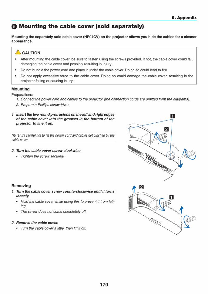
170
9. Appendix
❺ Mounting the cable cover (sold separately)
Mountingtheseparatelysoldcablecover(NP04CV)ontheprojectorallowsyouhidethecablesforacleanerappearance.
CAUTION• Aftermountingthecablecover,besuretofastenusingthescrewsprovided.Ifnot,thecablecovercouldfall,damagingthecablecoverandpossiblyresultingininjury.
• Donotbundlethepowercordandplaceitunderthecablecover.Doingsocouldleadtofire.
• Donotapplyexcessive forceto thecablecover.Doingsocoulddamagethecablecover, resulting in theprojectorfallingorcausinginjury.
MountingPreparations:
1. Connectthepowercordandcablestotheprojector(theconnectioncordsareomittedfromthediagrams).
2. PrepareaPhillipsscrewdriver.
1. Insert the two round protrusions on the left and right edges of the cable cover into the grooves in the bottom of the projector to line it up.
NOTE:Becarefulnottoletthepowercordandcablesgetpinchedbythecable cover.
2. Turn the cable cover screw clockwise.
• Tightenthescrewsecurely.
1
2
Removing1. Turn the cable cover screw counterclockwise until it turns
loosely.
• Holdthecablecoverwhiledoingthistopreventitfromfall-ing.
• Thescrewdoesnotcomecompletelyoff.
2. Remove the cable cover.
• Turnthecablecoveralittle,thenliftitoff.
1
2

171
9. Appendix
❻ Pin assignments and signal names of main connectorsCOMPUTER IN/ Component Input Connector (Mini D-Sub 15 Pin)
Connection and signal level of each pin
51 42 310
11 12 13 14 156 97 8
Signal LevelVideosignal:0.7Vp-p(Analog)Syncsignal:TTLlevel
Pin No. RGBSignal(Analog) YCbCr Signal1 Red Cr2 GreenorSynconGreen Y3 Blue Cb4 Ground5 Ground6 RedGround CrGround7 GreenGround YGround8 BlueGround CbGround9 NoConnection10 SyncSignalGround11 NoConnection12 Bi-directionalDATA(SDA)13 HorizontalSyncorCompositeSync14 VerticalSync15 DataClock
HDMI 1 IN/HDMI 2 IN Connector (Type A)
1 3 5 7 9 11 13 15 17 192 4 6 8 10 12 14 16 18
Pin No. Signal Pin No. Signal1 TMDSData2+ 11 TMDSClockShield2 TMDSData2Shield 12 TMDSClock−3 TMDSData2− 13 CEC4 TMDSData1+ 14 Disconnection5 TMDSData1Shield 15 SCL6 TMDSData1− 16 SDA7 TMDSData0+ 17 DDC/CECgrounding8 TMDSData0Shield 18 +5Vpowersupply9 TMDSData0− 19 Hotplugdetection10 TMDSClock+
DisplayPort IN Connector
1 3 5 7 9 11 13 15 17 192 4 6 8 10 12 14 16 18 20
Pin No. Signal Pin No. Signal1 Mainlinklane3− 11 Grounding02 Grounding3 12 Mainlinklane0+3 Mainlinklane3+ 13 Configuration14 Mainlinklane2− 14 Configuration25 Grounding2 15 Supplementarychannel+6 Mainlinklane2+ 16 Grounding47 Mainlinklane1− 17 Supplementarychannel−8 Grounding1 18 Hotplugdetection9 Mainlinklane1+ 19 Return10 Mainlinklane0− 20 +3.3Vpowersupply
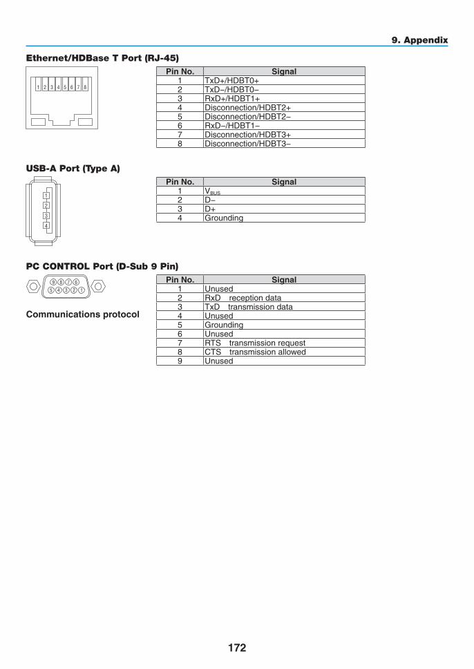
172
9. Appendix
Ethernet/HDBase T Port (RJ-45)
1 2 3 4 5 6 7 8
Pin No. Signal1 TxD+/HDBT0+2 TxD−/HDBT0−3 RxD+/HDBT1+4 Disconnection/HDBT2+5 Disconnection/HDBT2−6 RxD−/HDBT1−7 Disconnection/HDBT3+8 Disconnection/HDBT3−
USB-A Port (Type A)
1
3
2
4
Pin No. Signal1 VBUS2 D−3 D+4 Grounding
PC CONTROL Port (D-Sub 9 Pin)
12345
6789
Communications protocol
Pin No. Signal1 Unused2 RxD receptiondata3 TxD transmissiondata4 Unused5 Grounding6 Unused7 RTS transmissionrequest8 CTS transmissionallowed9 Unused

173
9. Appendix
❼ TroubleshootingThissectionhelpsyouresolveproblemsyoumayencounterwhilesettinguporusingtheprojector.
Indicator Messages
Power Indicator
Indicatordisplay Projectorstatus ProcedureOff Powerisoff. –Flashing Blue(shortflashes) Preparingtoturnpoweron Waitawhile.
Blue(longflashes) Offtimer(enabled)Programtimer(offtimeenabled)
–
Orange(shortflashes)
Projectorcooling Waitawhile.
Orange(longflashes) Programtimer(ontimeenabled)Lit Blue Poweron –
Red Standbymode(NORMAL) –Orange Standbymode(HDBaseTSTANDBY) –
Status Indicator
Indicatordisplay Projectorstatus ProcedureOff Noproblem,or
standbymode–
Flashing Red(cyclesof1)
Coverproblem Thelampcoverisnotproperlymounted.Mountitproperly.(→ Page144)
Red(cyclesof4)
Fanproblem Thecoolingfanhasstoppedturning.ContactanNECprojectorcustomersupportcenterforrepairs.
Flashing Orange Networkconflict It is not possible to connect theprojector’s built-in LANandwirelessLANsimultaneouslytothesamenetwork.Toconnecttheprojector’sbuilt-inLANandwirelessLANsimultaneously,connectthemtodifferentnetworks.
Lit Green STANDBYMODEinsleepmode*
–
Orange Buttonhasbeenpressedwhileprojec-torisinkeylockmode
Theprojector’skeysarelocked.Thesettingmustbecanceledtooperatetheprojector.(→Page104)
Projector’sIDnumberandremotecontrol’sIDnumberdonotmatch
CheckthecontrolIDs.(→Pages105)
* Sleepmodereferstothestatewherebythefunctionalrestrictionsduetothestandbymodesettingareremoved.

174
9. Appendix
Lamp Indicator
Indicatordisplay Projectorstatus ProcedureOff Thelampisturnedoff. –Flashing Green Preparingtorelightlampafter
lightinghasfailedWaitawhile.
Red Lampreplacementgraceperiod
Thelamphasreachedtheendofitsservicelifeandisnowinthereplacementgraceperiod(100hours).Re-placethelampassoonaspossible.(→page142)
Red(cyclesof6)
Lampdoesnotlight Thelamphasnotturnedon.Waitatleast1minute,thenturnthepowerbackon.Ifthelampstilldoesnotlight,contactanNECprojectorcustomersupportcenter.
Lit Red Lampusagetimeexceeded Thelamphasexceededitsusagetime.Theprojector’spowercannotbeturnedonuntilthelampisreplaced.(→page142)
Green Lamplit –
Temp. Indicator
Indicatordisplay Projectorstatus ProcedureOff NoproblemFlashing Red(cyclesof2) Temperatureproblem The temperature protector has beenactivated. If the
roomtemperatureishigh,movetheprojectortoacoolplace.Iftheproblemstillpersists,contactanNECprojec-torcustomersupportcenter.
Lit Orange Highsurroundingtemperature Thesurroundingtemperature ishigh.Lower theroomtemperature.
If the temperature protector is activatedIftheprojector’sinternaltemperaturerisesabnormally,thelampturnsoffandthetemperatureindicatorflashes(re-peatedlyincyclesof2).Itmayhappenthattheprojector’stemperatureprotectorissimultaneouslyactivatedandtheprojector’spowerturnsoff.Ifthishappens,dothefollowing:- Unplugthepowercordfromthepoweroutlet.
- Ifusinginaplacewherethesurroundingtemperatureishigh,movetheprojectortoadifferent,coolplace.
- Ifthereisdustintheventilationholes,clean.(→pages138and141)
- Waitassuchabout1hourfortheprojector’sinternaltemperaturetolower.

175
9. Appendix
Common Problems & Solutions(→“Power/Status/LampIndicator”onpage174.)
Problem CheckTheseItems
Does not turn onor shut down
• Checkthatthepowercordispluggedinandthatthepowerbuttonontheprojectorcabinetortheremotecontrolis on� (→ pages 13, 14)
• Ensurethatthelampcoverisinstalledcorrectly.(→ page 144)• Checktoseeiftheprojectorhasoverheated.Ifthereisinsufficientventilationaroundtheprojectororiftheroom
where you are presenting is particularly warm, move the projector to a cooler location�• Checktoseeifyoucontinuetousetheprojectorforanother100hoursafterthelamphasreachedtheendofits
life� If so, replace the lamp� After replacing the lamp, reset the lamp hours used� (→ page 116)• Thelampmayfailtolight.Waitafullminuteandthenturnonthepoweragain.• Set[FANMODE]to[HIGHALTITUDE]whenusingtheprojectorataltitudesapproximately5500feet/1600meters
or higher� Using the projector at altitudes approximately 5500 feet/1600 meters or higher without setting to [HIGH ALTITUDE] can cause the projector to overheat and the projector could shut down� If this happens, wait a couple minutes and turn on the projector� (→ page 97)
If you turn on the projector immediately after the lamp is turned off, the fans run without displaying an image for some time and then the projector will display the image� Wait for a moment�
Will turn off • Ensurethatthe[OFFTIMER],[AUTOPOWEROFF]or[PROGRAMTIMER]isoff.(→ page 100, 115)
No picture • Checkiftheappropriateinputisselected.(→ page 16) If there is still no picture, press the INPUT button or one of the input buttons again�
• Ensureyourcablesareconnectedproperly.• Usemenustoadjustthebrightnessandcontrast.(→ page 76)• Ensurethatthelenscoverisopen.(→ page 14)• Resetthesettingsoradjustmentstofactorypresetlevelsusingthe[RESET]intheMenu.(→ page 116)• EnteryourregisteredkeywordiftheSecurityfunctionisenabled.(→ page 36)• IftheHDMIinputortheDisplayPortsignalcannotbedisplayed,trythefollowing.
- Reinstall your driver for the graphics card built in your computer, or use the updated driver� For reinstalling or updating your driver, refer to the user guide accompanied with your computer or graphics
card, or contact the support center for your computer manufacturer� Install the updated driver or OS on your own responsibility� We are not liable for any trouble and failure caused by this installation�
• SignalsmaynotbesupporteddependingontheHDBaseTtransmissiondevice.IRandRS232Ccannotbeusedin certain cases as well�
• BesuretoconnecttheprojectorandnotebookPCwhiletheprojectorisinstandbymodeandbeforeturningonthe power to the notebook PC�
In most cases the output signal from the notebook PC is not turned on unless connected to the projector before being powered up�* If the screen goes blank while using your remote control, it may be the result of the computer’s screen-saver
or power management software�• Seealsothepage177�
Picture suddenly becomes dark
• CheckiftheprojectorisintheForcedECOmodebecauseoftoohighambienttemperature.Ifthisisthecase,lower the internal temperature of the projector by selecting [HIGH] for [FAN MODE]� (→ page 97)
Color tone or hue is unusual
• Checkifanappropriatecolorisselectedin[WALLCOLOR].Ifso,selectanappropriateoption.(→ page 97)• Adjust[HUE]in[PICTURE].(→ page 77)
Image isn’t square to the screen
• Repositiontheprojectortoimproveitsangletothescreen.(→ page 18)• UsetheKeystonecorrectionfunctiontocorrectthetrapezoiddistortion.(→ page 33)
Picture is blurred • Adjustthefocus.(→ page 20)• Repositiontheprojectortoimproveitsangletothescreen.(→ page 18)• Ensure that the distance between the projector and screen is within the adjustment range of the lens.
(→ page 158)• Hasthelensbeenshiftedbyanamountexceedingtheguaranteedrange?(→ page 162)• Condensationmayformonthelensiftheprojectoriscold,broughtintoawarmplaceandisthenturnedon.
Should this happen, let the projector stand until there is no condensation on the lens�
Flicker appears on screen
• Set[FANMODE]tootherthan[HIGHALTITUDE]modewhenusingtheprojectorataltitudesapproximately5500feet/1600 meters or lower� Using the projector at altitudes less than approximately 5500 feet/1600 meters and setting to [HIGH ALTITUDE] can cause the lamp to overcool, causing the image to flicker� Switch [FAN MODE] to [AUTO]� (→ page 97)
Image is scrolling vertically, horizontally or both
• Checkthecomputer’sresolutionandfrequency.Makesurethattheresolutionyouaretryingtodisplayissupportedby the projector� (→ page 164)
• AdjustthecomputerimagemanuallywiththeHorizontal/Verticalinthe[IMAGEOPTIONS].(→ page 79)

176
9. Appendix
Problem CheckTheseItems
Remote control does not work
• Installnewbatteries.(→ page 10)• Makesuretherearenoobstaclesbetweenyouandtheprojector.• Standwithin22feet(7m)oftheprojector.(→ page 11)• Toperformcomputermouseoperationsusingtheprojector’sremotecontrol,connecttheoptionalmousereceiver
to the computer� (→ page 31)
Indicator is lit or blinking
• SeethePOWER/STATUS/LAMPIndicator.(→ page 173)
Cross color in RGB mode
• PresstheAUTOADJ.buttonontheprojectorcabinetortheremotecontrol.(→ page 24)• Adjustthecomputerimagemanuallywith[CLOCK]/[PHASE]in[IMAGEOPTIONS]inthemenu.(→ page 78)
Formoreinformationcontactyourdealer.

177
9. Appendix
If there is no picture, or the picture is not displayed correctly.
• PoweronprocessfortheprojectorandthePC.
BesuretoconnecttheprojectorandnotebookPCwhiletheprojectorisinstandbymodeandbeforeturningonthepowertothenotebookPC.
InmostcasestheoutputsignalfromthenotebookPCisnotturnedonunlessconnectedtotheprojectorbeforebeingpoweredup.
NOTE:Youcancheckthehorizontalfrequencyofthecurrentsignalintheprojector’smenuunderInformation.Ifitreads“0kHz”,this means there is no signal being output from the computer. (→ page 119 or go to next step)
• Enablingthecomputer’sexternaldisplay.
DisplayinganimageonthenotebookPC’sscreendoesnotnecessarilymeanitoutputsasignaltotheprojector.WhenusingaPCcompatiblelaptop,acombinationoffunctionkeyswillenable/disabletheexternaldisplay.Usu-ally,thecombinationofthe“Fn”keyalongwithoneofthe12functionkeysgetstheexternaldisplaytocomeonoroff.Forexample,NEClaptopsuseFn+F3,whileDelllaptopsuseFn+F8keycombinationstotogglethroughexternaldisplayselections.
• Non-standardsignaloutputfromthecomputer
IftheoutputsignalfromanotebookPCisnotanindustrystandard,theprojectedimagemaynotbedisplayedcorrectly.Shouldthishappen,deactivatethenotebookPC’sLCDscreenwhentheprojectordisplayisinuse.EachnotebookPChasadifferentwayofdeactivate/reactivatethelocalLCDscreensasdescribedinthepreviousstep.Refertoyourcomputer’sdocumentationfordetailedinformation.
• ImagedisplayedisincorrectwhenusingaMac
WhenusingaMacwiththeprojector,settheDIPswitchoftheMacadapter(notsuppliedwiththeprojector)ac-cordingtoyourresolution.Aftersetting,restartyourMacforthechangestotakeaffect.
ForsettingdisplaymodesotherthanthosesupportedbyyourMacandtheprojector,changingtheDIPswitchonaMacadaptermaybounceanimageslightlyormaydisplaynothing.Shouldthishappen,settheDIPswitchtothe13"fixedmodeandthenrestartyourMac.Afterthat,restoretheDIPswitchestoadisplayablemodeandthenrestarttheMacagain.
NOTE:AVideoAdaptercablemanufacturedbyAppleComputerisneededforaMacBookwhichdoesnothaveaminiD-Sub15-pin connector.
• MirroringonaMacBook
* WhenusingtheprojectorwithaMacBook,outputmaynotbesetto1024×768unless“mirroring”isoffonyourMacBook.Refertoowner’smanualsuppliedwithyourMaccomputerformirroring.
• FoldersoriconsarehiddenontheMacscreen
Foldersoriconsmaynotbeseenonthescreen.Shouldthishappen,select[View]→[Arrange]fromtheApplemenuandarrangeicons.
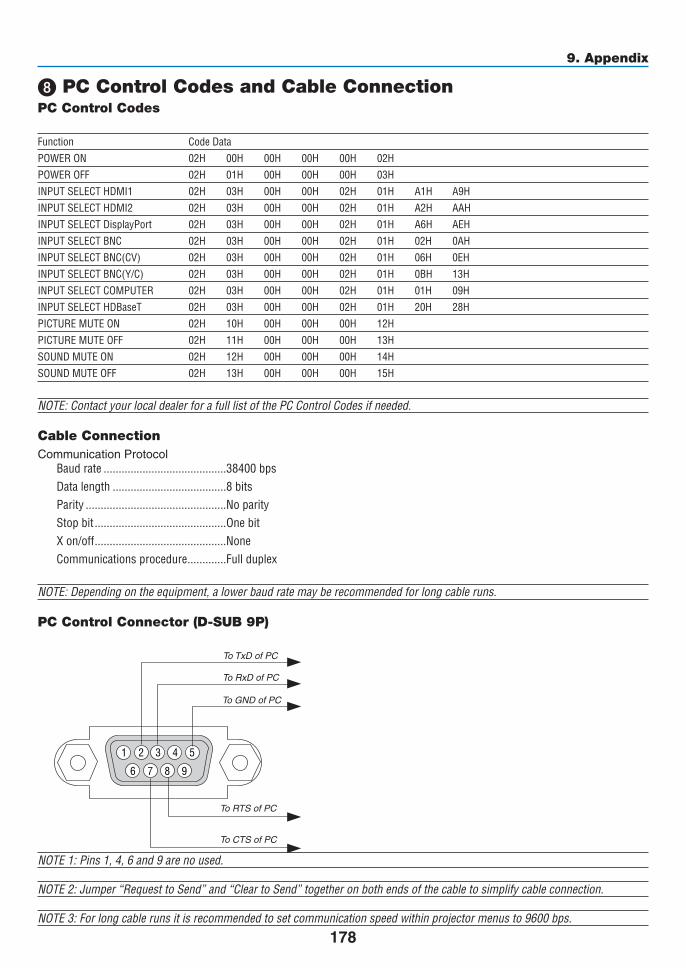
178
9. Appendix
❽ PC Control Codes and Cable ConnectionPC Control Codes
Function Code Data
POWER ON 02H 00H 00H 00H 00H 02H
POWER OFF 02H 01H 00H 00H 00H 03H
INPUT SELECT HDMI1 02H 03H 00H 00H 02H 01H A1H A9H
INPUT SELECT HDMI2 02H 03H 00H 00H 02H 01H A2H AAH
INPUT SELECT DisplayPort 02H 03H 00H 00H 02H 01H A6H AEH
INPUT SELECT BNC 02H 03H 00H 00H 02H 01H 02H 0AH
INPUT SELECT BNC(CV) 02H 03H 00H 00H 02H 01H 06H 0EH
INPUT SELECT BNC(Y/C) 02H 03H 00H 00H 02H 01H 0BH 13H
INPUT SELECT COMPUTER 02H 03H 00H 00H 02H 01H 01H 09H
INPUT SELECT HDBaseT 02H 03H 00H 00H 02H 01H 20H 28H
PICTURE MUTE ON 02H 10H 00H 00H 00H 12H
PICTURE MUTE OFF 02H 11H 00H 00H 00H 13H
SOUND MUTE ON 02H 12H 00H 00H 00H 14H
SOUND MUTE OFF 02H 13H 00H 00H 00H 15H
NOTE:ContactyourlocaldealerforafulllistofthePCControlCodesifneeded.
Cable ConnectionCommunicationProtocol
Baud rate �����������������������������������������38400 bpsData length ��������������������������������������8 bitsParity �����������������������������������������������No parityStop bit ��������������������������������������������One bitX on/off ��������������������������������������������NoneCommunications procedure �������������Full duplex
NOTE:Dependingontheequipment,alowerbaudratemayberecommendedforlongcableruns.
PC Control Connector (D-SUB 9P)
NOTE 1: Pins 1, 4, 6 and 9 are no used.
NOTE2:Jumper“RequesttoSend”and“CleartoSend”togetheronbothendsofthecabletosimplifycableconnection.
NOTE3:Forlongcablerunsitisrecommendedtosetcommunicationspeedwithinprojectormenusto9600bps.
1 52 43
6 7 98
ToGNDofPC
ToRxDofPC
ToTxDofPC
ToRTSofPC
ToCTSofPC
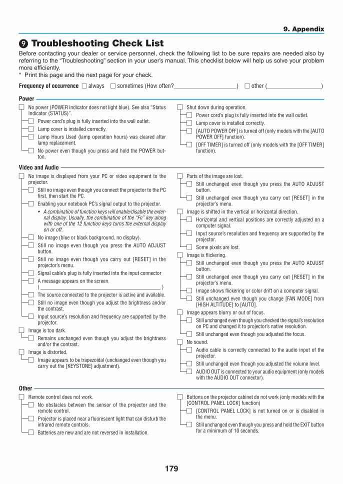
179
9. Appendix
❾ Troubleshooting Check ListBeforecontactingyourdealerorservicepersonnel,checkthefollowinglisttobesurerepairsareneededalsobyreferringtothe“Troubleshooting”sectioninyouruser’smanual.Thischecklistbelowwillhelpussolveyourproblemmoreefficiently.* Printthispageandthenextpageforyourcheck.
Frequency of occurrence □ always □sometimes(Howoften?_____________________) □other(__________________)
Power□ No power (POWER indicator does not light blue)� See also “Status
Indicator (STATUS)”�Power cord’s plug is fully inserted into the wall outlet�□
Lamp cover is installed correctly�□
Lamp Hours Used (lamp operation hours) was cleared after □lamp replacement�No power even though you press and hold the POWER but-□ton�
□ Shut down during operation�Power cord’s plug is fully inserted into the wall outlet�□
Lamp cover is installed correctly�□
[AUTO POWER OFF] is turned off (only models with the [AUTO □POWER OFF] function)�[OFF TIMER] is turned off (only models with the [OFF TIMER] □function)�
Video and Audio□ No image is displayed from your PC or video equipment to the
projector�Still no image even though you connect the projector to the PC □first, then start the PC�Enabling your notebook PC’s signal output to the projector�□
• Acombinationoffunctionkeyswillenable/disabletheexter-naldisplay.Usually,thecombinationofthe“Fn”keyalongwithoneofthe12functionkeysturnstheexternaldisplayon or off.
No image (blue or black background, no display)�□
Still no image even though you press the AUTO ADJUST □button�Still no image even though you carry out [RESET] in the □projector’s menu�Signal cable’s plug is fully inserted into the input connector□
A message appears on the screen�□(_____________________________________________)The source connected to the projector is active and available�□
Still no image even though you adjust the brightness and/or □the contrast�Input source’s resolution and frequency are supported by the □projector�
□ Image is too dark�Remains unchanged even though you adjust the brightness □and/or the contrast�
□ Image is distorted�Image appears to be trapezoidal (unchanged even though you □carry out the [KEYSTONE] adjustment)�
□ Parts of the image are lost�Still unchanged even though you press the AUTO ADJUST □button�Still unchanged even though you carry out [RESET] in the □projector’s menu�
□ Image is shifted in the vertical or horizontal direction�Horizontal and vertical positions are correctly adjusted on a □computer signal�Input source’s resolution and frequency are supported by the □projector�Some pixels are lost�□
□ Image is flickering�Still unchanged even though you press the AUTO ADJUST □button�Still unchanged even though you carry out [RESET] in the □projector’s menu�Image shows flickering or color drift on a computer signal�□
Still unchanged even though you change [FAN MODE] from □[HIGH ALTITUDE] to [AUTO]�
□ Image appears blurry or out of focus�Still unchanged even though you checked the signal’s resolution □on PC and changed it to projector’s native resolution�Still unchanged even though you adjusted the focus�□
□ No sound�Audio cable is correctly connected to the audio input of the □projector�Still unchanged even though you adjusted the volume level�□
AUDIO OUT is connected to your audio equipment (only models □with the AUDIO OUT connector)�
Other□ Remote control does not work�
No obstacles between the sensor of the projector and the □remote control�Projector is placed near a fluorescent light that can disturb the □infrared remote controls�Batteries are new and are not reversed in installation� □
□ Buttons on the projector cabinet do not work (only models with the [CONTROL PANEL LOCK] function)
[CONTROL PANEL LOCK] is not turned on or is disabled in □the menu�Still unchanged even though you press and hold the EXIT button □for a minimum of 10 seconds�

180
9. Appendix
In the space below please describe your problem in detail.
Information on application and environment where your projector is used
Projector PC
Blu-rayplayer
Projector
Model number:Serial No�:Date of purchase:Lamp operating time (hours):Eco Mode: □ OFF □ ONInformation on input signal:
Horizontal synch frequency [ ] kHzVertical synch frequency [ ] HzSynch polarity H □ (+) □ (−) V □ (+) □ (−)Synch type □ Separate □ Composite □ Sync on Green
STATUS Indicator:Steady light □ Orange □ GreenFlashing light [ ] cycles
Remote control model number:
Installation environment
Screen size: inchScreen type: □ White matte □ Beads □ Polarization
□ Wide angle □ High contrastThrow distance: feet/inch/mOrientation: □ Ceiling mount □ DesktopPower outlet connection:□ Connected directly to wall outlet□ Connected to power cord extender or other (the
numberofconnectedequipment______________)□ Connected to a power cord reel or other (the number
ofconnectedequipment______________)
Computer
Manufacturer:
Model number:
Notebook PC □ / Desktop □
Native resolution:
Refresh rate:
Video adapter:
Other:
Videoequipment
VCR, Blu-ray player, Video camera, Video game or other
Manufacturer:
Model number:Signal cable
NECstandardorothermanufacturer’scable?Model number: Length: inch/m
Distribution amplifierModel number:
SwitcherModel number:
AdapterModel number:

©NECDisplaySolutions,Ltd.2014 7N951971