prolec ltd., 25 benson road, nuffield industrial estate ...€¦ · prolec ltd. cannot anticipate...
TRANSCRIPT
560371-000 Issue 2.01
Weighloader
Operators Manual
Prolec Ltd., 25 Benson Road, Nuffield Industrial Estate, Poole, Dorset, England BH17 0GB

560371-000 Issue 2.01

560371-000 Issue 2.01
Note: Prolec Ltd. reserves the right to amend specifications, information and designs without notice. Prolec Ltd. cannot anticipate every possible circumstance that might involve a potential hazard and the warnings given in this manual are not all inclusive. The correct functioning of this equipment is dependant upon correct installation, calibration and user operation.
560371-000 Issue 2.01
Contents Page 1 Introduction 3 2 Weighloader Operation screen 5 2.1 Using Menu & Alpha numeric keypad 6 3 Totalise Weighing – Quick Reference 7 4 Target Weighing – Quick Reference 8 5 Switching On 9 6 Forced Tare Operation 9 7 Tare 10 8 Switching Off 11 9 Standby Mode 11 10 Weighing Mode selection 12 11 Kickout Weighing 13 12 Fly By Weighing 14 13 Totalise Weighing 15 13.1 Selecting Totalise Weighing 15 13.2 Manual Add 15 13.3 Auto Add 15 14 Target Weighing 16 14.1 Selecting Target Weighing 16 14.2 Target – Operation 17 14.3 Manual Add 17 14.4 Auto Add 17 14.5 Entering New Target 18 15 Load Units selection 19
Weighloader - Operators Manual
Page 1

560371-000 Issue 2.01
Contents Page 16 Display Settings 20 17 Bucket Selection 21 17.1 Editing Bucket Name 21 18 Products and Long Totals 22 18.1 Viewing & Selecting Product / Long Totals 22 18.2 Editing a Product / Long Total Name 23 18.3 Clearing Product / Long Totals record 23 19 Setting Time Date and Alarms 24 20 Operator Trim 26 20.1 Operator Trim Adjustment 26 20.2 Reset Trim 27 21 Printer Operations Introduction 28 21.1 Printing a Ticket 28 21.2 Printing Long Totals 29 21.3 Adding a Loader Name 30 21.4 Adding a Company Header 30 21.5 Adding a Operator Name 31 21.6 Adding a Customer Name 32 21.7 Adding a Comment 33 21.8 Changing the Paper Roll 34 21.9 Printer Diagnostics 34 22 Fault Finding Guide 35 22.1 General Operational Errors 35 22.2 Electrical Errors 35 22.3 Proximity Switch Errors 35 22.4 Diagnostics 36 22.5 Incorrect Loads 38 22.6 Error Table 39
Weighloader - Operators Manual
Page 2
560371-000 Issue 2.01
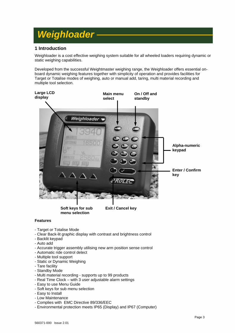
Soft keys for sub menu selection
Exit / Cancel key
On / Off and standby
Main menu select
Alpha-numeric keypad
Enter / Confirm key
Large LCD display
Features - Target or Totalise Mode - Clear Back-lit graphic display with contrast and brightness control - Backlit keypad - Auto add - Accurate trigger assembly utilising new arm position sense control - Automatic ride control detect - Multiple tool support - Static or Dynamic Weighing - Tare facility - Standby Mode - Multi material recording - supports up to 99 products - Real Time Clock – with 3 user adjustable alarm settings - Easy to use Menu Guide - Soft keys for sub menu selection - Easy to Install - Low Maintenance - Complies with EMC Directive 89/336/EEC - Environmental protection meets IP65 (Display) and IP67 (Computer)
1 Introduction
Weighloader Weighloader is a cost effective weighing system suitable for all wheeled loaders requiring dynamic or static weighing capabilities. Developed from the successful Weightmaster weighing range, the Weighloader offers essential on-board dynamic weighing features together with simplicity of operation and provides facilities for Target or Totalise modes of weighing, auto or manual add, taring, multi material recording and multiple tool selection.
Page 3
560371-000 Issue 2.01
Weighing operation A choice of two weighing operation types are provided : Kick-out weighing (static) or Fly By (dynamic) weighing. The system achieves its weighing by monitoring the pressures in the main lift ram at the selected trigger point. The trigger point is selected during calibration to give optimum performance. The trigger point is monitored using a specially designed sensor arrangement which provides an accurate point of reference and lift speed information.
Ride Control Ride control affects the arm ram pressures during lifting operations and has been known to cause problems with other weighing systems. Prolec recommend that for the best weighing performance ride control is switch off during weighing. Weighloader can monitor the ride control activity and be calibrated so that it automatically compensates for ride control. But this is very much dependent on make & model of loader. Testing at install will indicate if weighing with ride control enabled is possible.
Weighing Modes A choice of two weighing modes are offered : Totalise (Count Up) or Target (Count Down ) either of which are selectable during operation. Either mode can be operated with both weighing operation types. The ability to „trim‟ the final bucket when in target mode is possible with both weighing operation types. Totalise Mode provides the facility to monitor the accumulated loads lifted. Target Mode provides the ability to set a target load. This facility can be used when loading a truck etc. to its known (target) capacity.
Kick-out Weighing Kick-out weighing will stop the arm from being lifted any further when the trigger point is reached. This then allows the operator to move the machine whilst the weighing calculation is taking place. When the load is displayed the operator is then free to move the arm to the required height to tip off the load. Kick-out weighing provides the facility of a final bucket weighing which allows the operator to tip off a portion of the load until the preset target is reached (target / count down mode only). Fly-by Weighing Fly-by weighing allows the operator to continue the lifting of the arm past the trigger point. There is no speed restriction as the system automatically compensates for different arm lift speeds. It is rec-ommended that the machine remains static when weighing in this mode. Fly-by weighing provides the facility of a final bucket kick-out weighing which allows the operator to tip off a portion of the load until the preset target is reached (target / count down mode only).
Page 4
560371-000 Issue 2.01
Load Lifted
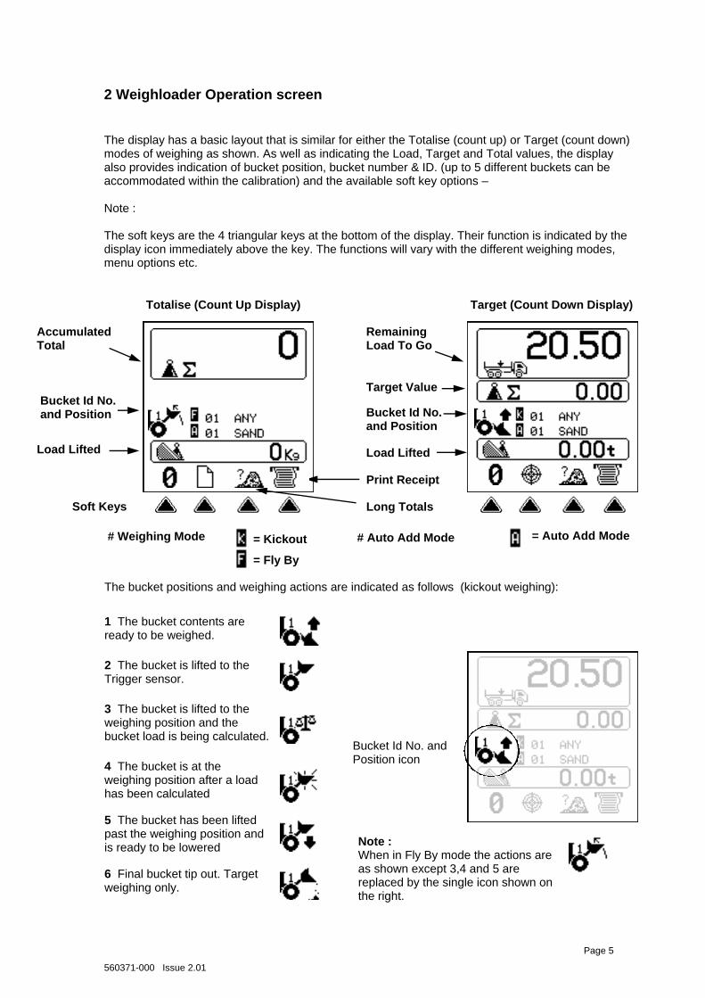
The display has a basic layout that is similar for either the Totalise (count up) or Target (count down) modes of weighing as shown. As well as indicating the Load, Target and Total values, the display also provides indication of bucket position, bucket number & ID. (up to 5 different buckets can be accommodated within the calibration) and the available soft key options – Note : The soft keys are the 4 triangular keys at the bottom of the display. Their function is indicated by the display icon immediately above the key. The functions will vary with the different weighing modes, menu options etc.
2 Weighloader Operation screen
The bucket positions and weighing actions are indicated as follows (kickout weighing):
1 The bucket contents are ready to be weighed.
2 The bucket is lifted to the Trigger sensor.
3 The bucket is lifted to the weighing position and the bucket load is being calculated.
4 The bucket is at the weighing position after a load has been calculated
5 The bucket has been lifted past the weighing position and is ready to be lowered
Totalise (Count Up Display) Target (Count Down Display)
Soft Keys
Accumulated Total
Load Lifted
Target Value
Remaining Load To Go
Bucket Id No. and Position
6 Final bucket tip out. Target weighing only.
Bucket Id No. and Position icon
Bucket Id No. and Position
Note : When in Fly By mode the actions are as shown except 3,4 and 5 are replaced by the single icon shown on the right.
Page 5
# Auto Add Mode = Auto Add Mode # Weighing Mode = Kickout
= Fly By
Print Receipt
Long Totals
560371-000 Issue 2.01
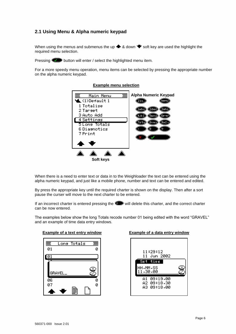
When using the menus and submenus the up & down soft key are used the highlight the required menu selection. Pressing button will enter / select the highlighted menu item. For a more speedy menu operation, menu items can be selected by pressing the appropriate number on the alpha numeric keypad.
Page 6
2.1 Using Menu & Alpha numeric keypad
Alpha Numeric Keypad
Soft keys
When there is a need to enter text or data in to the Weighloader the text can be entered using the alpha numeric keypad, and just like a mobile phone, number and text can be entered and edited. By press the appropriate key until the required charter is shown on the display. Then after a sort pause the curser will move to the next charter to be entered. If an incorrect charter is entered pressing the will delete this charter, and the correct charter can be now entered. The examples below show the long Totals recode number 01 being edited with the word “GRAVEL” and an example of time data entry windows.
Example menu selection
Example of a text entry window Example of a data entry window
560371-000 Issue 2.01
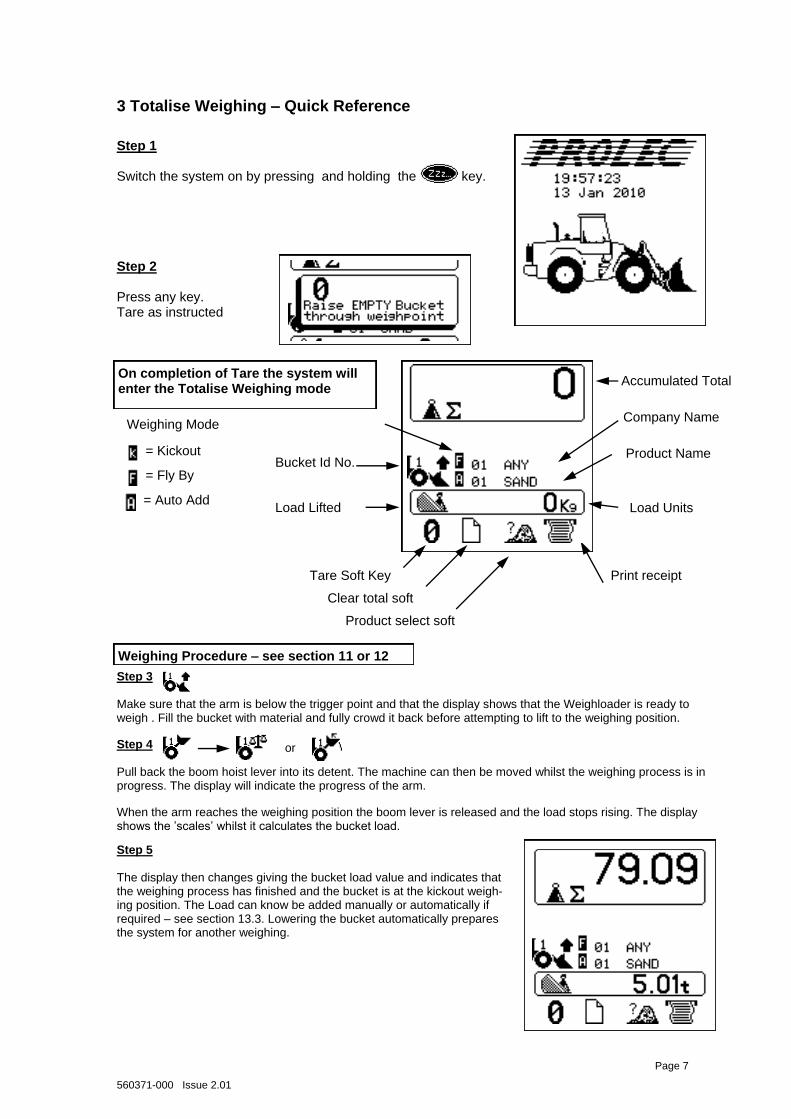
Product Name
3 Totalise Weighing – Quick Reference
Step 2 Press any key. Tare as instructed
Bucket Id No.
Accumulated Total
Load Lifted
Tare Soft Key
Clear total soft
On completion of Tare the system will enter the Totalise Weighing mode
Load Units
Step 4 Pull back the boom hoist lever into its detent. The machine can then be moved whilst the weighing process is in progress. The display will indicate the progress of the arm.
When the arm reaches the weighing position the boom lever is released and the load stops rising. The display shows the ‟scales‟ whilst it calculates the bucket load.
Step 5 The display then changes giving the bucket load value and indicates that the weighing process has finished and the bucket is at the kickout weigh-ing position. The Load can know be added manually or automatically if required – see section 13.3. Lowering the bucket automatically prepares the system for another weighing.
Step 3 Make sure that the arm is below the trigger point and that the display shows that the Weighloader is ready to weigh . Fill the bucket with material and fully crowd it back before attempting to lift to the weighing position.
Weighing Procedure – see section 11 or 12
Product select soft
or
Weighing Mode
= Kickout
= Fly By
Page 7
Company Name
Print receipt
= Auto Add
Step 1 Switch the system on by pressing and holding the key.
560371-000 Issue 2.01
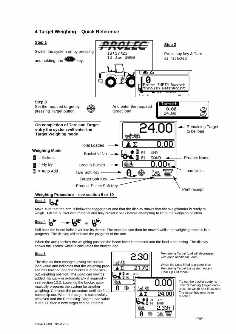
Target Soft Key
4 Target Weighing – Quick Reference
Step 2 Press any key & Tare as instructed
Bucket Id No
Remaining Target to be load
Load in Bucket
Tare Soft Key
On completion of Tare and Target entry the system will enter the Target Weighing mode
Load Units
Product Name
Step 3 Set the required target by pressing Target button
And enter the required target load
Total Loaded
Product Select Soft Key
When the arm reaches the weighing position the boom lever is released and the load stops rising. The display shows the ‟scales‟ whilst it calculates the bucket load.
Step 3 Make sure that the arm is below the trigger point and that the display shows that the Weighloader is ready to weigh . Fill the bucket with material and fully crowd it back before attempting to lift to the weighing position.
Weighing Procedure – see section 9 or 10
Step 4 Pull back the boom hoist lever into its detent. The machine can then be moved whilst the weighing process is in progress. The display will indicate the progress of the arm.
Remaining Target load will decreases with each additional Load
When the Load lifted is greater than Remaining Target the system enters Final Tip Out mode
Tip out the bucket contents until Remaining Target load = 0.00. Re weigh and if OK add. The target has now been reached.
Step 5 The display then changes giving the bucket load value and indicates that the weighing proc-ess has finished and the bucket is at the kick-out weighing position. The Load can now be added manually or automatically if required – see section 13.3. Lowering the bucket auto-matically prepares the system for another weighing. Continue the procedure until the final bucket tip out. When the target is successfully achieved and the Remaining Target Load value is at 0.00 then a new target can be entered.
or
Weighing Mode
= Kickout
= Fly By
Page 8
= Auto Add
Print receipt
Step 1 Switch the system on by pressing and holding the key.
560371-000 Issue 2.01
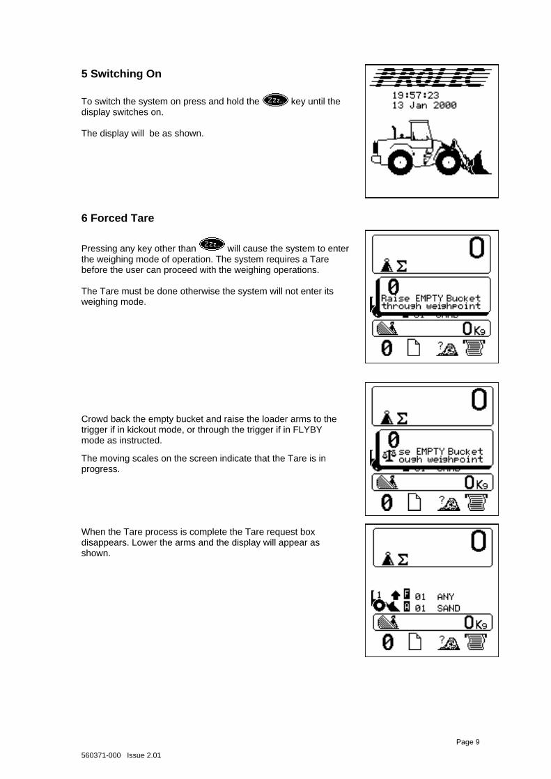
Crowd back the empty bucket and raise the loader arms to the trigger if in kickout mode, or through the trigger if in FLYBY mode as instructed.
The moving scales on the screen indicate that the Tare is in progress.
When the Tare process is complete the Tare request box disappears. Lower the arms and the display will appear as shown.
6 Forced Tare
Page 9
Pressing any key other than will cause the system to enter the weighing mode of operation. The system requires a Tare before the user can proceed with the weighing operations. The Tare must be done otherwise the system will not enter its weighing mode.
5 Switching On
To switch the system on press and hold the key until the display switches on. The display will be as shown.
560371-000 Issue 2.01
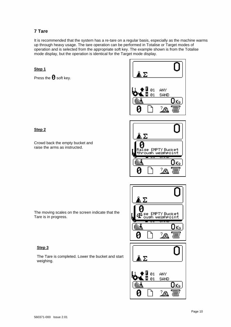
7 Tare
It is recommended that the system has a re-tare on a regular basis, especially as the machine warms up through heavy usage. The tare operation can be performed in Totalise or Target modes of operation and is selected from the appropriate soft key. The example shown is from the Totalise mode display, but the operation is identical for the Target mode display.
Step 1 Press the soft key.
Step 2 Crowd back the empty bucket and raise the arms as instructed.
The moving scales on the screen indicate that the Tare is in progress.
Step 3 The Tare is completed. Lower the bucket and start weighing.
Page 4 Page 10
560371-000 Issue 2.01
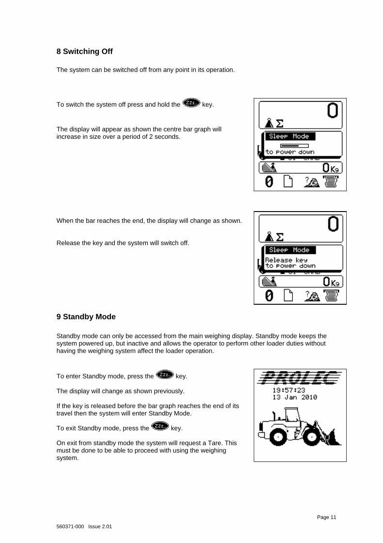
8 Switching Off
The system can be switched off from any point in its operation.
When the bar reaches the end, the display will change as shown. Release the key and the system will switch off.
9 Standby Mode
Standby mode can only be accessed from the main weighing display. Standby mode keeps the system powered up, but inactive and allows the operator to perform other loader duties without having the weighing system affect the loader operation.
Page 11
To enter Standby mode, press the key. The display will change as shown previously. If the key is released before the bar graph reaches the end of its travel then the system will enter Standby Mode. To exit Standby mode, press the key. On exit from standby mode the system will request a Tare. This must be done to be able to proceed with using the weighing system.
To switch the system off press and hold the key.
The display will appear as shown the centre bar graph will increase in size over a period of 2 seconds.
560371-000 Issue 2.01
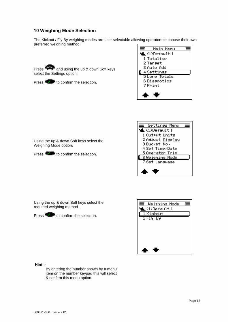
10 Weighing Mode Selection
The Kickout / Fly By weighing modes are user selectable allowing operators to choose their own preferred weighing method.
Using the up & down Soft keys select the required weighing method. Press to confirm the selection.
Using the up & down Soft keys select the Weighing Mode option. Press to confirm the selection.
Press and using the up & down Soft keys select the Settings option. Press to confirm the selection.
Page 12
Hint :- By entering the number shown by a menu item on the number keypad this will select & confirm this menu option.
560371-000 Issue 2.01
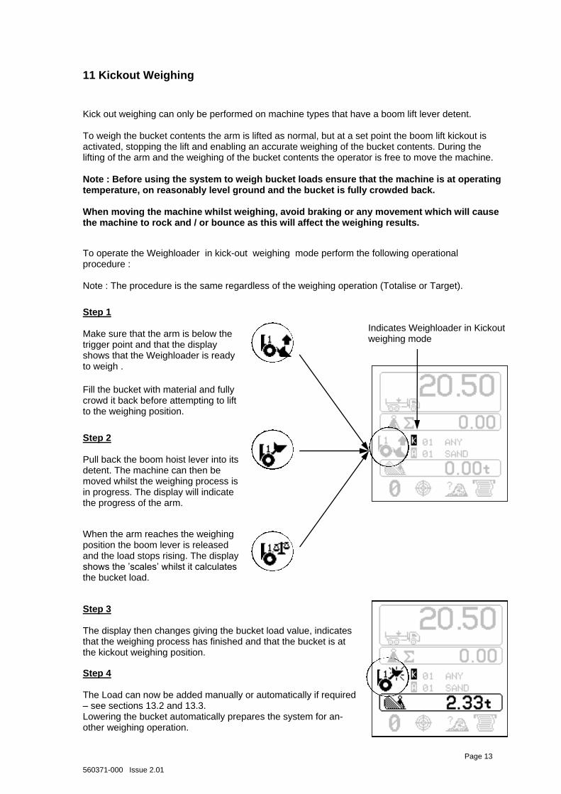
Kick out weighing can only be performed on machine types that have a boom lift lever detent. To weigh the bucket contents the arm is lifted as normal, but at a set point the boom lift kickout is activated, stopping the lift and enabling an accurate weighing of the bucket contents. During the lifting of the arm and the weighing of the bucket contents the operator is free to move the machine. Note : Before using the system to weigh bucket loads ensure that the machine is at operating temperature, on reasonably level ground and the bucket is fully crowded back. When moving the machine whilst weighing, avoid braking or any movement which will cause the machine to rock and / or bounce as this will affect the weighing results.
11 Kickout Weighing
To operate the Weighloader in kick-out weighing mode perform the following operational procedure : Note : The procedure is the same regardless of the weighing operation (Totalise or Target).
Step 2 Pull back the boom hoist lever into its detent. The machine can then be moved whilst the weighing process is in progress. The display will indicate the progress of the arm.
When the arm reaches the weighing position the boom lever is released and the load stops rising. The display shows the ‟scales‟ whilst it calculates the bucket load.
Step 3 The display then changes giving the bucket load value, indicates that the weighing process has finished and that the bucket is at the kickout weighing position.
Step 4 The Load can now be added manually or automatically if required – see sections 13.2 and 13.3. Lowering the bucket automatically prepares the system for an-other weighing operation.
Step 1 Make sure that the arm is below the trigger point and that the display shows that the Weighloader is ready to weigh .
Fill the bucket with material and fully crowd it back before attempting to lift to the weighing position.
Indicates Weighloader in Kickout weighing mode
Page 13
560371-000 Issue 2.01
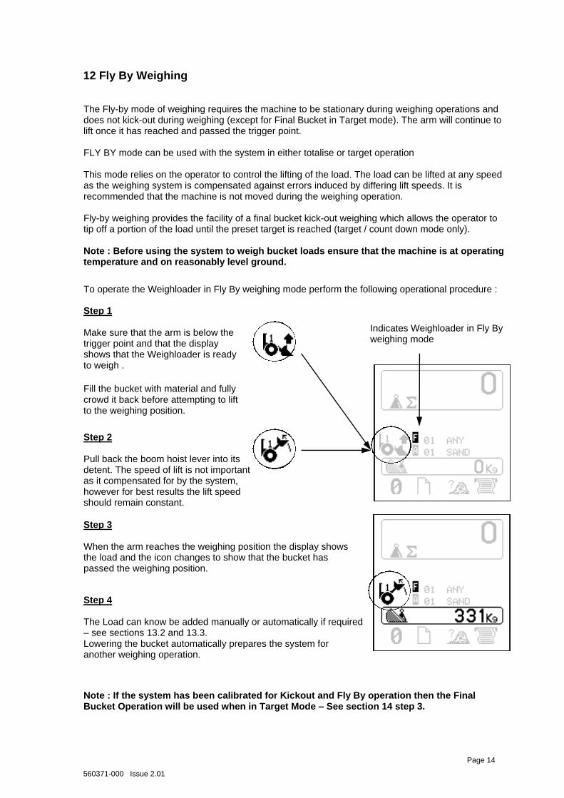
The Fly-by mode of weighing requires the machine to be stationary during weighing operations and does not kick-out during weighing (except for Final Bucket in Target mode). The arm will continue to lift once it has reached and passed the trigger point. FLY BY mode can be used with the system in either totalise or target operation This mode relies on the operator to control the lifting of the load. The load can be lifted at any speed as the weighing system is compensated against errors induced by differing lift speeds. It is recommended that the machine is not moved during the weighing operation. Fly-by weighing provides the facility of a final bucket kick-out weighing which allows the operator to tip off a portion of the load until the preset target is reached (target / count down mode only). Note : Before using the system to weigh bucket loads ensure that the machine is at operating temperature and on reasonably level ground.
12 Fly By Weighing
To operate the Weighloader in Fly By weighing mode perform the following operational procedure :
Step 2 Pull back the boom hoist lever into its detent. The speed of lift is not important as it compensated for by the system, however for best results the lift speed should remain constant.
Step 3 When the arm reaches the weighing position the display shows the load and the icon changes to show that the bucket has passed the weighing position.
Step 4 The Load can know be added manually or automatically if required – see sections 13.2 and 13.3. Lowering the bucket automatically prepares the system for another weighing operation.
Step 1 Make sure that the arm is below the trigger point and that the display shows that the Weighloader is ready to weigh .
Fill the bucket with material and fully crowd it back before attempting to lift to the weighing position.
Indicates Weighloader in Fly By weighing mode
Note : If the system has been calibrated for Kickout and Fly By operation then the Final Bucket Operation will be used when in Target Mode – See section 14 step 3.
Page 14
560371-000 Issue 2.01
Soft Keys select menu option
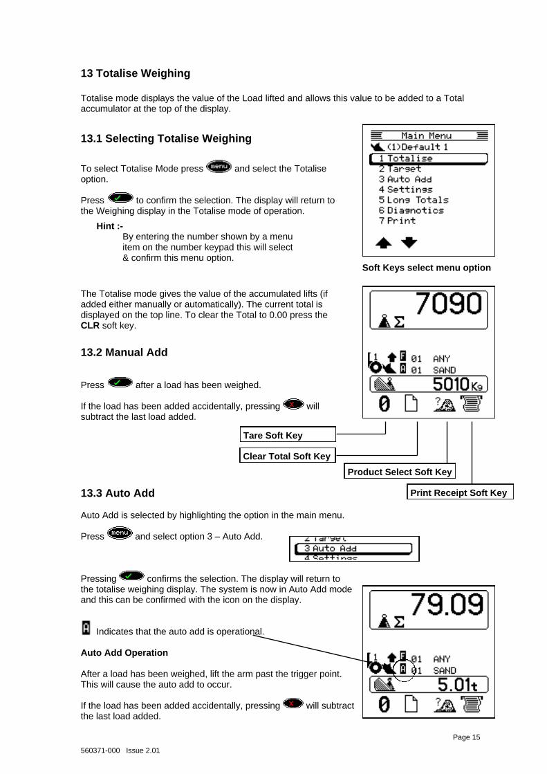
13 Totalise Weighing
Totalise mode displays the value of the Load lifted and allows this value to be added to a Total accumulator at the top of the display.
13.1 Selecting Totalise Weighing
Page 15
The Totalise mode gives the value of the accumulated lifts (if added either manually or automatically). The current total is displayed on the top line. To clear the Total to 0.00 press the CLR soft key.
To select Totalise Mode press and select the Totalise option. Press to confirm the selection. The display will return to the Weighing display in the Totalise mode of operation.
13.2 Manual Add Press after a load has been weighed. If the load has been added accidentally, pressing will subtract the last load added.
13.3 Auto Add Auto Add is selected by highlighting the option in the main menu. Press and select option 3 – Auto Add. Pressing confirms the selection. The display will return to the totalise weighing display. The system is now in Auto Add mode and this can be confirmed with the icon on the display.
Indicates that the auto add is operational.
Auto Add Operation After a load has been weighed, lift the arm past the trigger point. This will cause the auto add to occur. If the load has been added accidentally, pressing will subtract the last load added.
Hint :- By entering the number shown by a menu item on the number keypad this will select & confirm this menu option.
Clear Total Soft Key
Product Select Soft Key
Tare Soft Key
Print Receipt Soft Key
560371-000 Issue 2.01
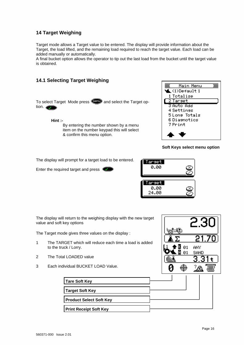
The Target mode gives three values on the display : 1 The TARGET which will reduce each time a load is added
to the truck / Lorry. 2 The Total LOADED value 3 Each individual BUCKET LOAD Value.
To select Target Mode press and select the Target op-tion.
Soft Keys select menu option
The display will prompt for a target load to be entered. Enter the required target and press
The display will return to the weighing display with the new target value and soft key options
Tare Soft Key
Target Soft Key
Product Select Soft Key
14 Target Weighing
Target mode allows a Target value to be entered. The display will provide information about the Target, the load lifted, and the remaining load required to reach the target value. Each load can be added manually or automatically. A final bucket option allows the operator to tip out the last load from the bucket until the target value is obtained.
14.1 Selecting Target Weighing
Page 16
Print Receipt Soft Key
Hint :- By entering the number shown by a menu item on the number keypad this will select & confirm this menu option.
560371-000 Issue 2.01
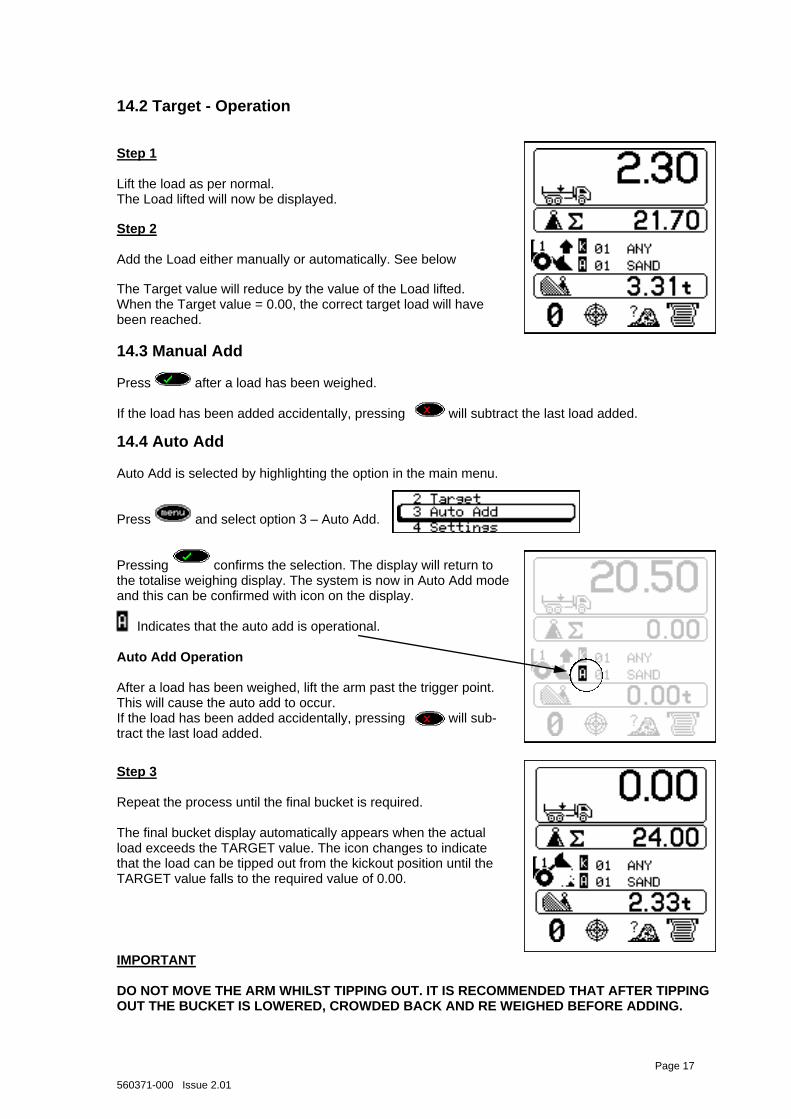
Step 3 Repeat the process until the final bucket is required. The final bucket display automatically appears when the actual load exceeds the TARGET value. The icon changes to indicate that the load can be tipped out from the kickout position until the TARGET value falls to the required value of 0.00.
14.2 Target - Operation
14.3 Manual Add Press after a load has been weighed. If the load has been added accidentally, pressing will subtract the last load added.
Step 1 Lift the load as per normal. The Load lifted will now be displayed.
The Target value will reduce by the value of the Load lifted. When the Target value = 0.00, the correct target load will have been reached.
Step 2 Add the Load either manually or automatically. See below
14.4 Auto Add Auto Add is selected by highlighting the option in the main menu. Press and select option 3 – Auto Add. Pressing confirms the selection. The display will return to the totalise weighing display. The system is now in Auto Add mode and this can be confirmed with icon on the display.
Indicates that the auto add is operational.
Auto Add Operation After a load has been weighed, lift the arm past the trigger point. This will cause the auto add to occur. If the load has been added accidentally, pressing will sub-tract the last load added.
IMPORTANT DO NOT MOVE THE ARM WHILST TIPPING OUT. IT IS RECOMMENDED THAT AFTER TIPPING OUT THE BUCKET IS LOWERED, CROWDED BACK AND RE WEIGHED BEFORE ADDING.
Page 17
560371-000 Issue 2.01
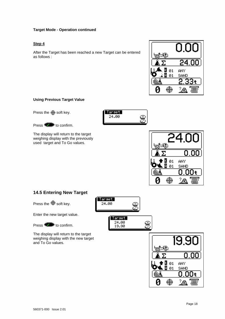
Target Mode - Operation continued
Step 4 After the Target has been reached a new Target can be entered as follows :
14.5 Entering New Target
Press the soft key.
Enter the new target value.
Using Previous Target Value
Press the soft key.
Page 18
Press to confirm. The display will return to the target weighing display with the previously used target and To Go values.
Press to confirm. The display will return to the target weighing display with the new target and To Go values.
560371-000 Issue 2.01
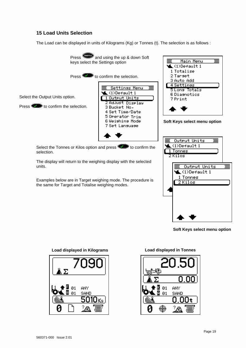
15 Load Units Selection
The Load can be displayed in units of Kilograms (Kg) or Tonnes (t). The selection is as follows :
Soft Keys select menu option
Examples below are in Target weighing mode. The procedure is the same for Target and Totalise weighing modes.
Soft Keys select menu option
Load displayed in Kilograms Load displayed in Tonnes
Page 19
Select the Tonnes or Kilos option and press to confirm the selection. The display will return to the weighing display with the selected units.
Select the Output Units option. Press to confirm the selection.
Press and using the up & down Soft keys select the Settings option Press to confirm the selection.
C
560371-000 Issue 2.01
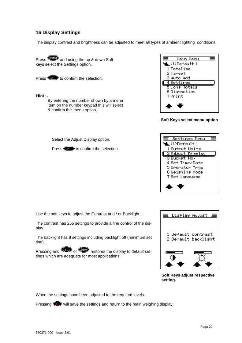
16 Display Settings
The display contrast and brightness can be adjusted to meet all types of ambient lighting conditions.
Soft Keys adjust respective setting.
Page 20
When the settings have been adjusted to the required levels. Pressing will save the settings and return to the main weighing display.
Press and using the up & down Soft keys select the Settings option. Press to confirm the selection.
Select the Adjust Display option. Press to confirm the selection.
Soft Keys select menu option
Use the soft keys to adjust the Contrast and / or Backlight. The contrast has 255 settings to provide a fine control of the dis-play. The backlight has 8 settings including backlight off (minimum set ting). Pressing and or restores the display to default set-tings which are adequate for most applications.
Hint :- By entering the number shown by a menu item on the number keypad this will select & confirm this menu option.
560371-000 Issue 2.01
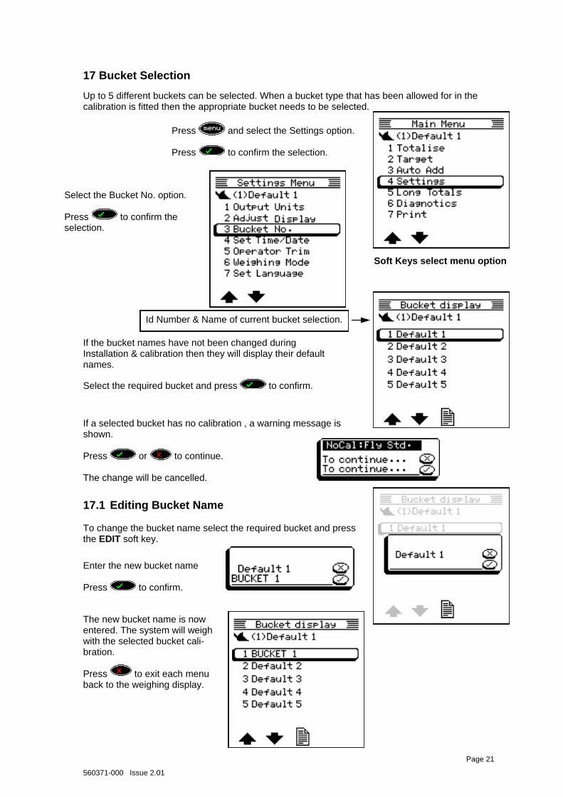
17 Bucket Selection
Up to 5 different buckets can be selected. When a bucket type that has been allowed for in the calibration is fitted then the appropriate bucket needs to be selected.
Soft Keys select menu option
If the bucket names have not been changed during Installation & calibration then they will display their default names.
Select the required bucket and press to confirm.
To change the bucket name select the required bucket and press the EDIT soft key.
Id Number & Name of current bucket selection.
17.1 Editing Bucket Name
Page 21
If a selected bucket has no calibration , a warning message is shown. Press or to continue. The change will be cancelled.
Press and select the Settings option. Press to confirm the selection.
Select the Bucket No. option. Press to confirm the selection.
The new bucket name is now entered. The system will weigh with the selected bucket cali-bration. Press to exit each menu back to the weighing display.
Enter the new bucket name Press to confirm.
560371-000 Issue 2.01
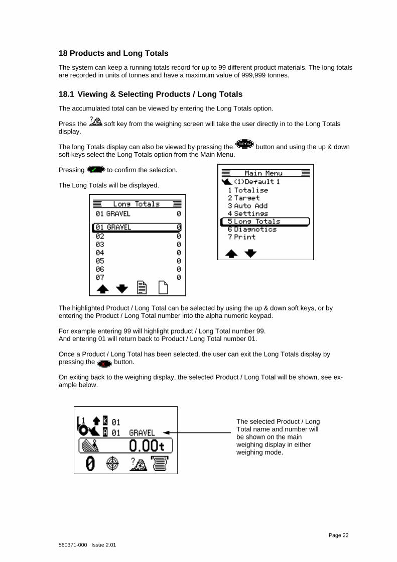
18 Products and Long Totals
The system can keep a running totals record for up to 99 different product materials. The long totals are recorded in units of tonnes and have a maximum value of 999,999 tonnes.
The accumulated total can be viewed by entering the Long Totals option. Press the soft key from the weighing screen will take the user directly in to the Long Totals display. The long Totals display can also be viewed by pressing the button and using the up & down soft keys select the Long Totals option from the Main Menu. Pressing to confirm the selection. The Long Totals will be displayed.
18.1 Viewing & Selecting Products / Long Totals
Page 22
The highlighted Product / Long Total can be selected by using the up & down soft keys, or by entering the Product / Long Total number into the alpha numeric keypad. For example entering 99 will highlight product / Long Total number 99. And entering 01 will return back to Product / Long Total number 01. Once a Product / Long Total has been selected, the user can exit the Long Totals display by pressing the button. On exiting back to the weighing display, the selected Product / Long Total will be shown, see ex-ample below.
The selected Product / Long Total name and number will be shown on the main weighing display in either weighing mode.
560371-000 Issue 2.01
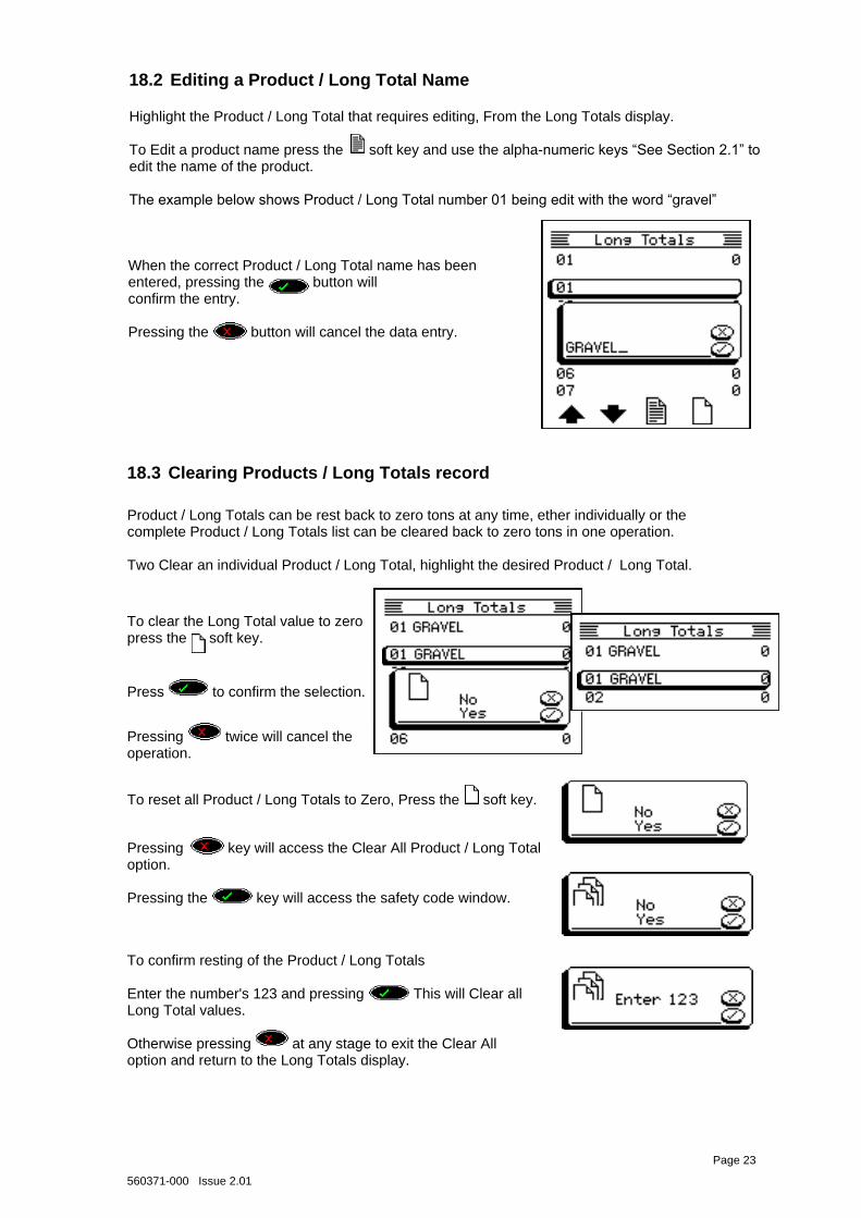
18.3 Clearing Products / Long Totals record
To confirm resting of the Product / Long Totals Enter the number's 123 and pressing This will Clear all Long Total values. Otherwise pressing at any stage to exit the Clear All option and return to the Long Totals display.
Page 23
Press to confirm the selection.
Pressing key will access the Clear All Product / Long Total option. Pressing the key will access the safety code window.
To clear the Long Total value to zero press the soft key.
18.2 Editing a Product / Long Total Name
Highlight the Product / Long Total that requires editing, From the Long Totals display. To Edit a product name press the soft key and use the alpha-numeric keys “See Section 2.1” to edit the name of the product. The example below shows Product / Long Total number 01 being edit with the word “gravel”
When the correct Product / Long Total name has been entered, pressing the button will confirm the entry. Pressing the button will cancel the data entry.
Product / Long Totals can be rest back to zero tons at any time, ether individually or the complete Product / Long Totals list can be cleared back to zero tons in one operation. Two Clear an individual Product / Long Total, highlight the desired Product / Long Total.
Pressing twice will cancel the operation.
To reset all Product / Long Totals to Zero, Press the soft key.
560371-000 Issue 2.01
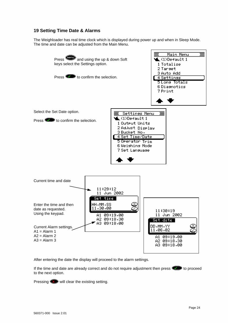
19 Setting Time Date & Alarms
The Weighloader has real time clock which is displayed during power up and when in Sleep Mode. The time and date can be adjusted from the Main Menu.
Enter the time and then date as requested. Using the keypad.
Current time and date
Current Alarm settings. A1 = Alarm 1 A2 = Alarm 2 A3 = Alarm 3
Page 24
After entering the date the display will proceed to the alarm settings. If the time and date are already correct and do not require adjustment then press to proceed to the next option. Pressing will clear the existing setting.
Press and using the up & down Soft keys select the Settings option. Press to confirm the selection.
Select the Set Date option. Press to confirm the selection.
560371-000 Issue 2.01
Set alarms 1,2 and 3 as required.
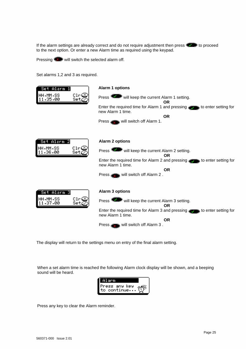
The display will return to the settings menu on entry of the final alarm setting.
Page 25
If the alarm settings are already correct and do not require adjustment then press to proceed to the next option. Or enter a new Alarm time as required using the keypad. Pressing will switch the selected alarm off.
When a set alarm time is reached the following Alarm clock display will be shown, and a beeping sound will be heard. Press any key to clear the Alarm reminder.
Alarm 1 options Press will keep the current Alarm 1 setting.
OR Enter the required time for Alarm 1 and pressing to enter setting for new Alarm 1 time.
OR Press will switch off Alarm 1.
Alarm 2 options Press will keep the current Alarm 2 setting.
OR Enter the required time for Alarm 2 and pressing to enter setting for new Alarm 1 time.
OR Press will switch off Alarm 2 .
Alarm 3 options Press will keep the current Alarm 3 setting.
OR Enter the required time for Alarm 3 and pressing to enter setting for new Alarm 1 time.
OR Press will switch off Alarm 3 .
560371-000 Issue 2.01
20 Operator Trim
It is possible for the system to be adjusted by the operator for any discrepancies that may occur when the system is being compared to a Weighbridge during Truck loading operations.
If the results of the Weighloader differs from the Weighbridge by an unacceptable amount that exceeds the system specification then the procedure for adjustment is as follows :
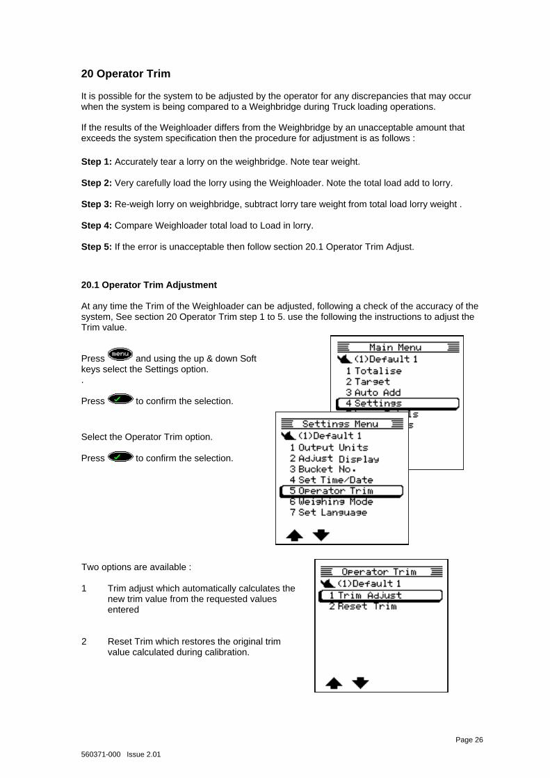
Two options are available : 1 Trim adjust which automatically calculates the new trim value from the requested values entered 2 Reset Trim which restores the original trim value calculated during calibration.
Page 26
Press and using the up & down Soft keys select the Settings option. . Press to confirm the selection.
Select the Operator Trim option. Press to confirm the selection.
Step 1: Accurately tear a lorry on the weighbridge. Note tear weight. Step 2: Very carefully load the lorry using the Weighloader. Note the total load add to lorry. Step 3: Re-weigh lorry on weighbridge, subtract lorry tare weight from total load lorry weight . Step 4: Compare Weighloader total load to Load in lorry. Step 5: If the error is unacceptable then follow section 20.1 Operator Trim Adjust.
20.1 Operator Trim Adjustment At any time the Trim of the Weighloader can be adjusted, following a check of the accuracy of the system, See section 20 Operator Trim step 1 to 5. use the following the instructions to adjust the Trim value.
560371-000 Issue 2.01
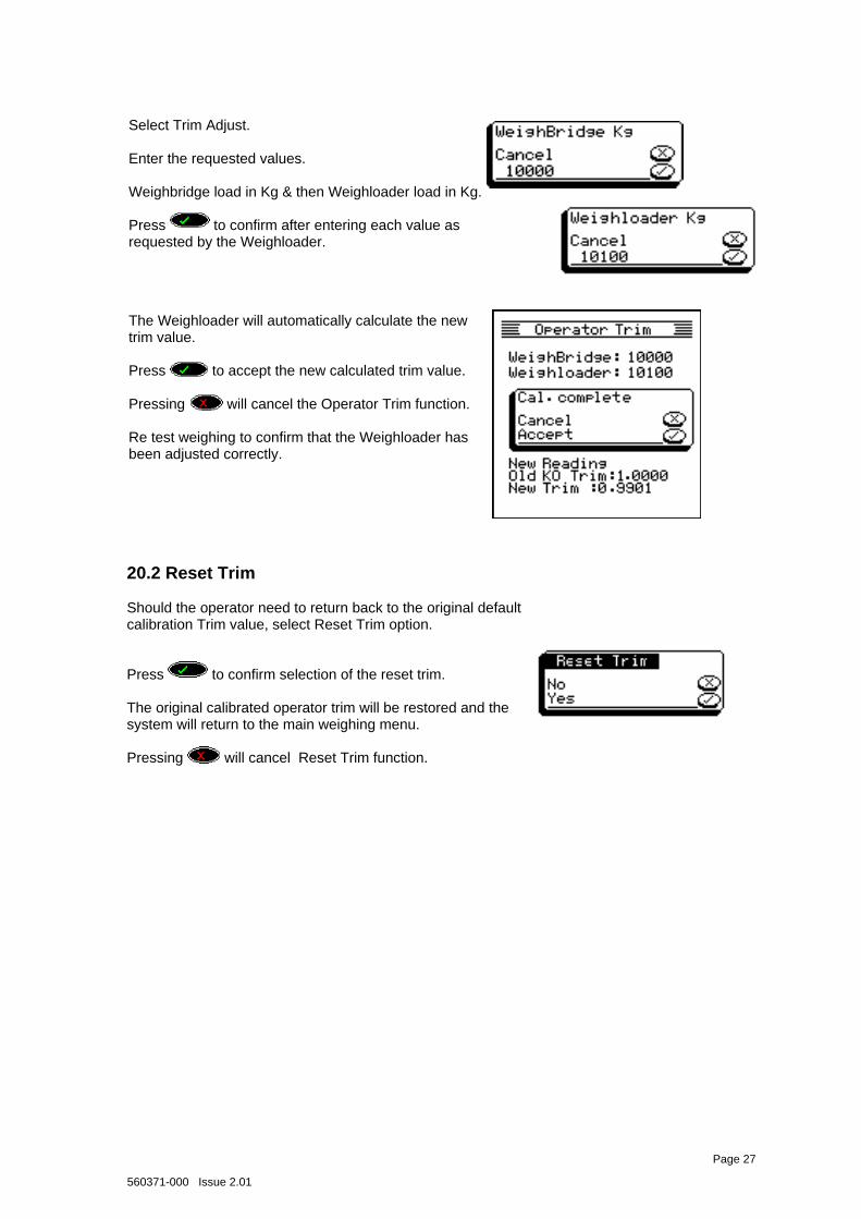
20.2 Reset Trim Should the operator need to return back to the original default calibration Trim value, select Reset Trim option. Press to confirm selection of the reset trim. The original calibrated operator trim will be restored and the system will return to the main weighing menu. Pressing will cancel Reset Trim function.
Page 27
Select Trim Adjust. Enter the requested values. Weighbridge load in Kg & then Weighloader load in Kg. Press to confirm after entering each value as requested by the Weighloader.
The Weighloader will automatically calculate the new trim value. Press to accept the new calculated trim value. Pressing will cancel the Operator Trim function. Re test weighing to confirm that the Weighloader has been adjusted correctly.
560371-000 Issue 2.01
Page 28
21 Printer Operations Introduction The Weighloader Printer offers a simple method of providing a hardcopy of what has been loaded. The printer output can be left at the default output or you can add as many of the fields which are discussed below.
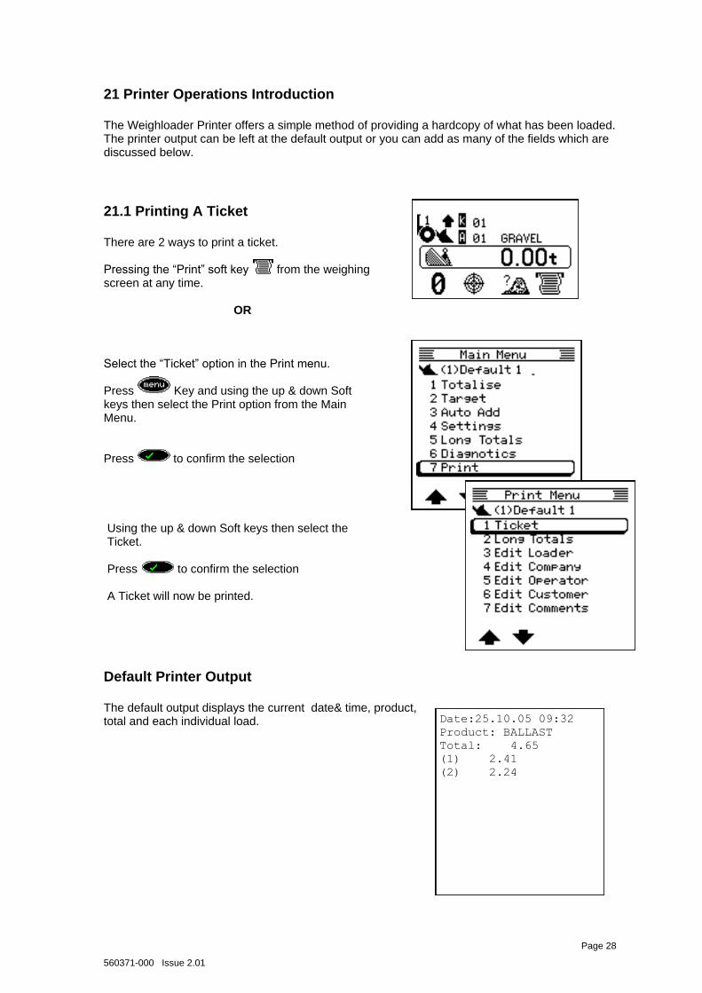
21.1 Printing A Ticket There are 2 ways to print a ticket. Pressing the “Print” soft key from the weighing screen at any time.
OR
Default Printer Output The default output displays the current date& time, product, total and each individual load.
Date:25.10.05 09:32
Product: BALLAST
Total: 4.65
(1) 2.41
(2) 2.24
Select the “Ticket” option in the Print menu. Press Key and using the up & down Soft keys then select the Print option from the Main Menu. Press to confirm the selection
Using the up & down Soft keys then select the Ticket. Press to confirm the selection A Ticket will now be printed.
560371-000 Issue 2.01
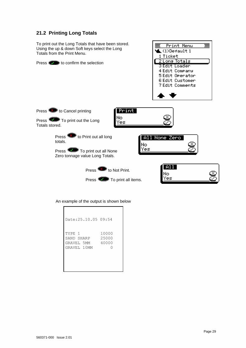
21.2 Printing Long Totals To print out the Long Totals that have been stored. Using the up & down Soft keys select the Long Totals from the Print Menu. Press to confirm the selection
Date:25.10.05 09:54
TYPE 1 10000
SAND SHARP 25000
GRAVEL 5MM 40000
GRAVEL 10MM 0
An example of the output is shown below
Page 29
Press to Cancel printing Press To print out the Long Totals stored.
Press to Print out all long totals. Press To print out all None Zero tonnage value Long Totals.
Press to Not Print. Press To print all items.
560371-000 Issue 2.01
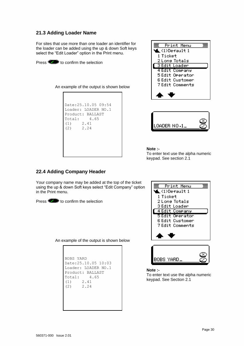
21.3 Adding Loader Name For sites that use more than one loader an identifier for the loader can be added using the up & down Soft keys select the “Edit Loader” option in the Print menu. Press to confirm the selection
Date:25.10.05 09:54
Loader: LOADER NO.1
Product: BALLAST
Total: 4.65
(1) 2.41
(2) 2.24
An example of the output is shown below
Page 30
22.4 Adding Company Header Your company name may be added at the top of the ticket using the up & down Soft keys select “Edit Company” option in the Print menu. Press to confirm the selection
BOBS YARD
Date:25.10.05 10:03
Loader: LOADER NO.1
Product: BALLAST
Total: 4.65
(1) 2.41
(2) 2.24
An example of the output is shown below
Note :- To enter text use the alpha numeric keypad. See section 2.1
Note :- To enter text use the alpha numeric keypad. See Section 2.1
560371-000 Issue 2.01
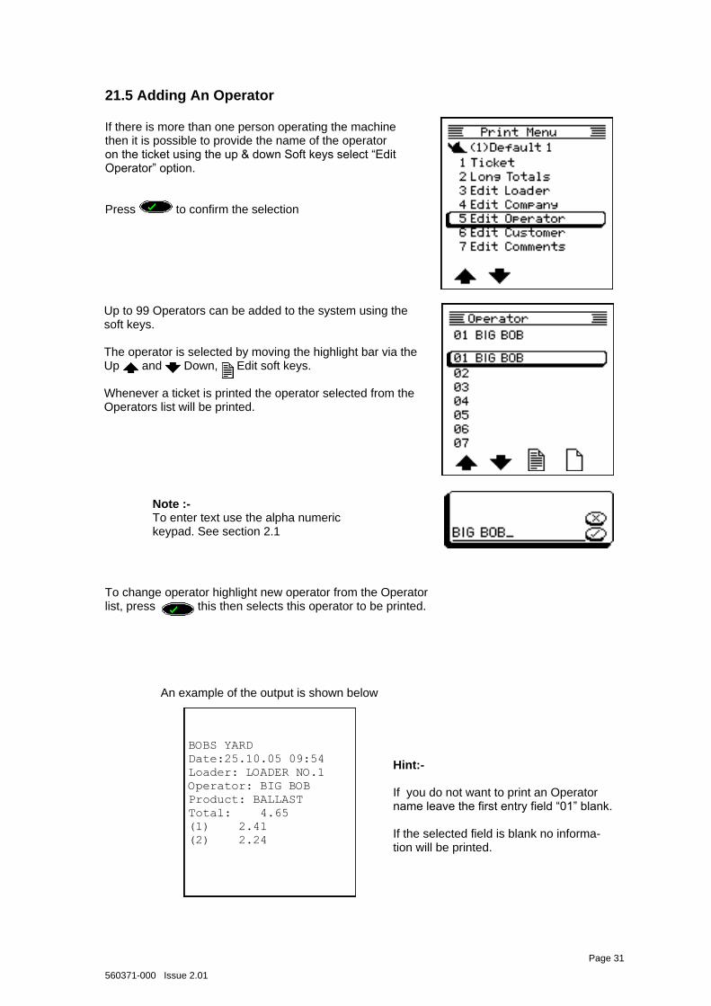
21.5 Adding An Operator If there is more than one person operating the machine then it is possible to provide the name of the operator on the ticket using the up & down Soft keys select “Edit Operator” option. Press to confirm the selection
BOBS YARD
Date:25.10.05 09:54
Loader: LOADER NO.1
Operator: BIG BOB
Product: BALLAST
Total: 4.65
(1) 2.41
(2) 2.24
An example of the output is shown below
Page 31
Up to 99 Operators can be added to the system using the soft keys. The operator is selected by moving the highlight bar via the Up and Down, Edit soft keys. Whenever a ticket is printed the operator selected from the Operators list will be printed.
To change operator highlight new operator from the Operator list, press this then selects this operator to be printed.
Hint:- If you do not want to print an Operator name leave the first entry field “01” blank. If the selected field is blank no informa-tion will be printed.
Note :- To enter text use the alpha numeric keypad. See section 2.1
560371-000 Issue 2.01
Page 32
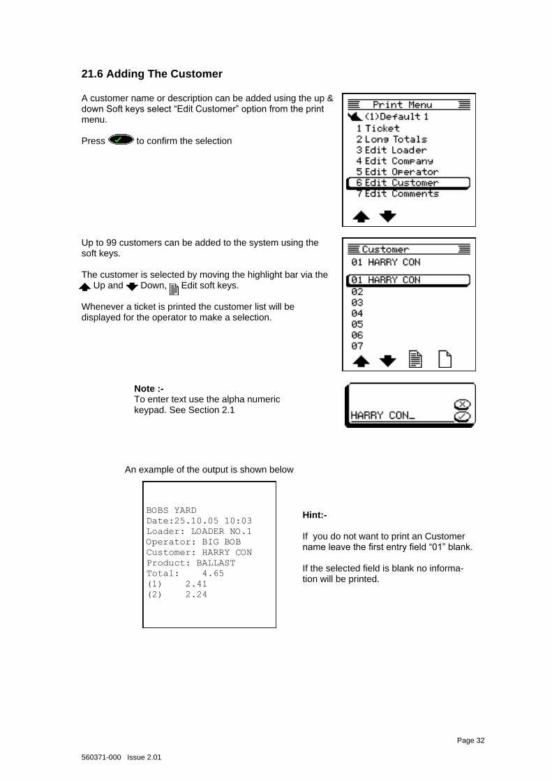
21.6 Adding The Customer A customer name or description can be added using the up & down Soft keys select “Edit Customer” option from the print menu. Press to confirm the selection
BOBS YARD
Date:25.10.05 10:03
Loader: LOADER NO.1
Operator: BIG BOB
Customer: HARRY CON
Product: BALLAST
Total: 4.65
(1) 2.41
(2) 2.24
An example of the output is shown below
Up to 99 customers can be added to the system using the soft keys. The customer is selected by moving the highlight bar via the
Up and Down, Edit soft keys.
Whenever a ticket is printed the customer list will be displayed for the operator to make a selection.
Hint:- If you do not want to print an Customer name leave the first entry field “01” blank. If the selected field is blank no informa-tion will be printed.
Note :- To enter text use the alpha numeric keypad. See Section 2.1
560371-000 Issue 2.01
Page 33
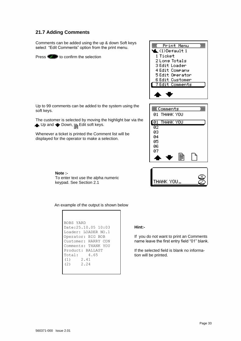
21.7 Adding Comments Comments can be added using the up & down Soft keys select “Edit Comments” option from the print menu. Press to confirm the selection
BOBS YARD
Date:25.10.05 10:03
Loader: LOADER NO.1
Operator: BIG BOB
Customer: HARRY CON
Comments: THANK YOU
Product: BALLAST
Total: 4.65
(1) 2.41
(2) 2.24
An example of the output is shown below
Up to 99 comments can be added to the system using the soft keys. The customer is selected by moving the highlight bar via the
Up and Down, Edit soft keys.
Whenever a ticket is printed the Comment list will be displayed for the operator to make a selection.
Hint:- If you do not want to print an Comments name leave the first entry field “01” blank. If the selected field is blank no informa-tion will be printed.
Note :- To enter text use the alpha numeric keypad. See Section 2.1
560371-000 Issue 2.01
Page 34
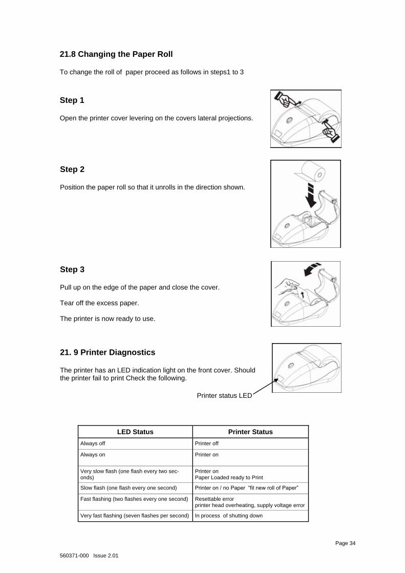
21.8 Changing the Paper Roll To change the roll of paper proceed as follows in steps1 to 3
Step 1 Open the printer cover levering on the covers lateral projections.
Step 2 Position the paper roll so that it unrolls in the direction shown.
Step 3 Pull up on the edge of the paper and close the cover. Tear off the excess paper. The printer is now ready to use.
21. 9 Printer Diagnostics The printer has an LED indication light on the front cover. Should the printer fail to print Check the following.
Printer status LED
LED Status Printer Status
Always off Printer off
Always on Printer on
Very slow flash (one flash every two sec-onds)
Printer on Paper Loaded ready to Print
Slow flash (one flash every one second) Printer on / no Paper “fit new roll of Paper”
Fast flashing (two flashes every one second) Resettable error printer head overheating, supply voltage error
Very fast flashing (seven flashes per second) In process of shutting down
560371-000 Issue 2.01
22 Fault Finding Guide The Weighloader is an advanced computer controlled weighing system and no attempt to repair any component of the system should be made by anyone other than a PROLEC service engineer or agent. Prolec supports a nation-wide network of fully trained service engineers. Warranty claims, service work, technical information and spare parts are available by contacting : Prolec Ltd 25 Benson Road Nuffield Industrial Estate Poole Dorset BH17 0GB Tel: 01202 681190 Fax: 01202 677909 There are some system faults which can be resolved on site and the following provides a guide for the investigation of these faults.
22.1 General Operational If the system does not perform as expected during its operation refer to the relevant section of the operators manual. If a particular aspect of the system is providing troublesome to use and cannot be solved by reference to the operators manual then call Prolec for assistance. This may save time and money if the need of a PROLEC service engineer is not actually required.
22.2 Electrical Errors If the system will not switch on, check the following : a) Check the power cable and system cable from the computer/display for damage. b) Check for any blown fuses (inline with the power cable or within the fuse box). Replace any damaged fuses with the same type & rating fuse and retry the system. If the system will still not switch on then the system requires the attention of a PROLEC service engineer.
22.3 Proximity Switch Errors If when operating the system in its Kickout Weighing or Fly-By mode the weight of the load does not appear on the display or the kick out (Kickout Weighing only) does not occur during weighing, check the following : a) Use the Diagnostics option See Section 22.4 and check for proximity switch operation. If a switch is faulty then : b) Check that the 'trigger switch assembly' is still in position and passes near the proximity sensors when the arm is lifted. If the 'trigger finger' is not in the required position (is bent or damaged) then it needs to be moved to the correct position. If this is not possible or the correct position is unknown then the system requires the attention of a PROLEC service engineer. c) Check the cable between the proximity sensors and computer box for damage. If the cable is damaged then the system requires the attention of a PROLEC service engineer. If the weight of the load does still not appear during weighing, then contact Prolec for support, we will try to resolve the problem by phone.
Page 35
560371-000 Issue 2.01
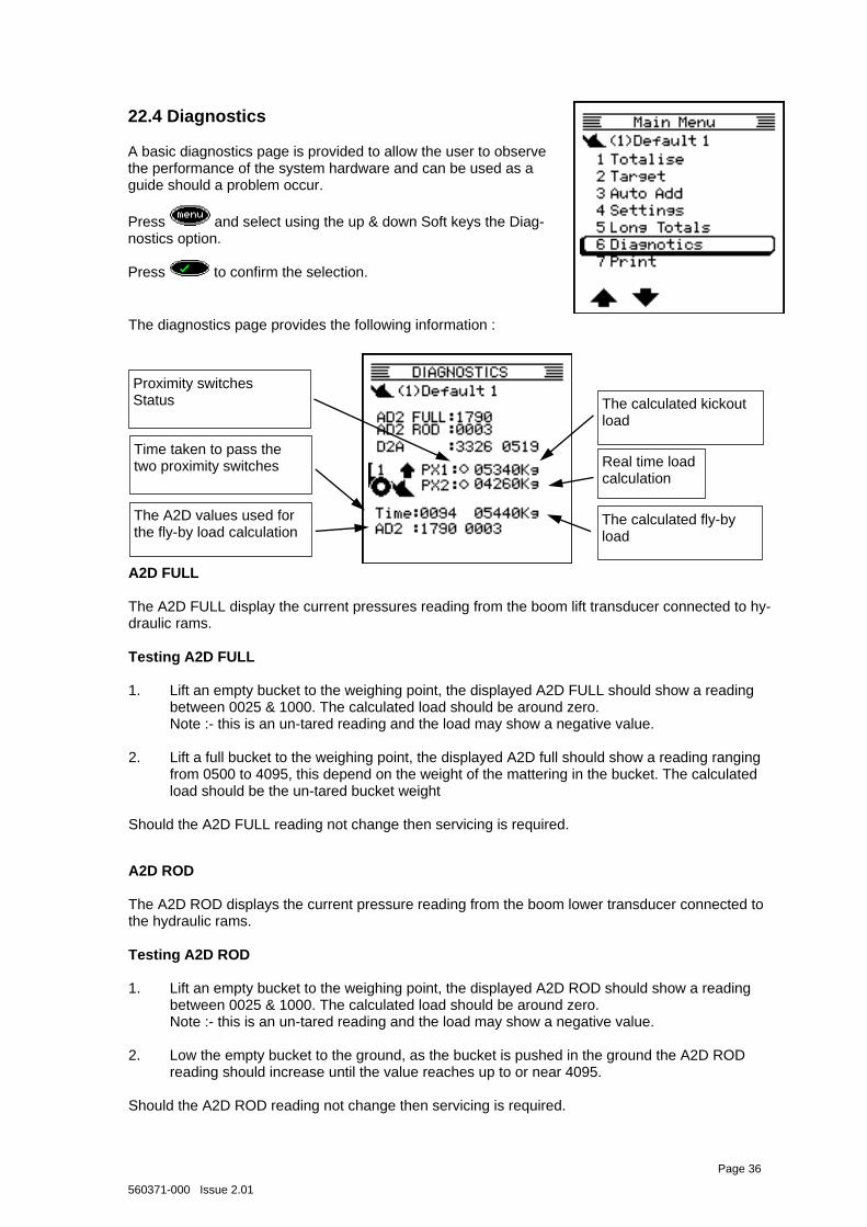
22.4 Diagnostics
A basic diagnostics page is provided to allow the user to observe the performance of the system hardware and can be used as a guide should a problem occur.
A2D FULL The A2D FULL display the current pressures reading from the boom lift transducer connected to hy-draulic rams. Testing A2D FULL 1. Lift an empty bucket to the weighing point, the displayed A2D FULL should show a reading
between 0025 & 1000. The calculated load should be around zero. Note :- this is an un-tared reading and the load may show a negative value. 2. Lift a full bucket to the weighing point, the displayed A2D full should show a reading ranging from 0500 to 4095, this depend on the weight of the mattering in the bucket. The calculated load should be the un-tared bucket weight Should the A2D FULL reading not change then servicing is required.
A2D ROD The A2D ROD displays the current pressure reading from the boom lower transducer connected to the hydraulic rams. Testing A2D ROD 1. Lift an empty bucket to the weighing point, the displayed A2D ROD should show a reading
between 0025 & 1000. The calculated load should be around zero. Note :- this is an un-tared reading and the load may show a negative value. 2. Low the empty bucket to the ground, as the bucket is pushed in the ground the A2D ROD
reading should increase until the value reaches up to or near 4095. Should the A2D ROD reading not change then servicing is required.
The diagnostics page provides the following information :
Page 36
Press and select using the up & down Soft keys the Diag-nostics option. Press to confirm the selection.
Real time load calculation
The calculated kickout load
Time taken to pass the two proximity switches
The A2D values used for the fly-by load calculation
The calculated fly-by load
Proximity switches Status
560371-000 Issue 2.01
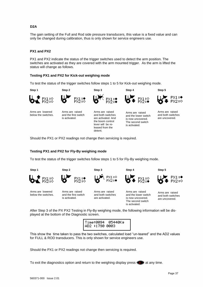
D2A The gain setting of the Full and Rod side pressure transducers, this value is a fixed value and can only be changed during calibration, thus is only shown for service engineers use.
PX1 and PX2 PX1 and PX2 indicate the status of the trigger switches used to detect the arm position. The switches are activated as they are covered with the arm mounted trigger. As the arm is lifted the status will change as follows.
To exit the diagnostics option and return to the weighing display press at any time.
Page 37
Testing PX1 and PX2 for Kick-out weighing mode To test the status of the trigger switches follow steps 1 to 5 for Kick-out weighing mode.
Should the PX1 or PX2 readings not change then servicing is required.
Arms are raised and the lower switch is now uncovered. The second switch is activated.
Arms are lowered below the switches.
Arms are raised and the first switch is activated.
Arms are raised and both switches are activated.
Arms are raised and both switches are uncovered.
Step 1 Step 2 Step 3 Step 4 Step 5
Arms are raised and the lower switch is now uncovered. The second switch is activated.
Arms are lowered below the switches.
Arms are raised and the first switch is activated.
Arms are raised and both switches are activated. And the boom control lever will be re-leased from the detent.
Arms are raised and both switches are uncovered.
Step 1 Step 2 Step 3 Step 4 Step 5
Testing PX1 and PX2 for Fly-By weighing mode To test the status of the trigger switches follow steps 1 to 5 for Fly-By weighing mode.
After Step 3 of the PX PX2 Testing in Fly-By weighing mode, the following information will be dis-played at the bottom of the Diagnostic screen. This show the time taken to pass the two switches, calculated load “un-teared” and the AD2 values for FULL & ROD transducers. This is only shown for service engineers use. Should the PX1 or PX2 readings not change then servicing is required.
560371-000 Issue 2.01
22.5 Incorrect Loads If the displayed weight is obviously incorrect then : a) Check that the bucket is empty before weighing or taring. b) Check that the transducer connections to the full and rod side of the arm lift ram are not damaged or leaking. c) Check that the proximity switches have not been disturbed. d) Follow the Operator Trim procedure – see section 20. e) If the performance of the Weighloader is questionable then copy the following page and fill the form in as recommended. Fax/send the completed form to Prolec. Prolec will check the recorded loads and offer advice about the performance of the Weighloader and take suitable action. Note : If unfamiliar with the operation then read the manual first
Page 38
560371-000 Issue 2.01
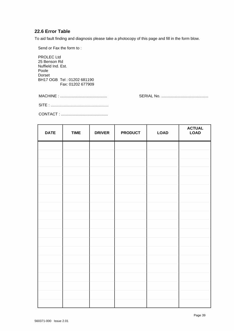
To aid fault finding and diagnosis please take a photocopy of this page and fill in the form blow.
DATE
TIME
DRIVER
PRODUCT
LOAD
ACTUAL LOAD
Send or Fax the form to : PROLEC Ltd 25 Benson Rd Nuffield Ind. Est. Poole Dorset BH17 OGB Tel : 01202 681190 Fax: 01202 677909
MACHINE : ........................................... SERIAL No. ........................................... SITE : ..................................................... CONTACT : ...........................................
22.6 Error Table
Page 39

560371-000 Issue 2.01
Servicing Prolec supports a nationwide network of fully trained service engineers. Warranty claims, service work, technical information and spare parts are available by contacting : Prolec Ltd 25 Benson Road Nuffield Industrial Estate Poole Dorset BH17 OGB Tel : 01202 681190

560371-000 Issue 2.01
Prolec Ltd., 25 Benson Road, Nuffield Industrial Estate, Poole, Dorset, England BH17 0GB
PROLEC LTD 25 BENSON ROAD NUFFIELD INDUSTRIAL ESTATE POOLE, DORSET ENGLAND, BH17 0GB Operators Manual 560371-000 Issue 2.01
+44 (0) 1202 681190
+44 (0) 1202 677909
www.prolec.co.uk