prolevel fmc 661 level measurement - axon automation€¦ · prolevel fmc 661 level measurement...
TRANSCRIPT

prolevelFMC 661Level Measurement
Operating Instructions
BA 142F/00/en/07.98a016562-1000valid for Software 1.x
Hauser+EndressNothing beats know-how


Short Instructions
..Quick configuration for level measurement
Function Matrix Action1 Reset transmitter V9H5 Enter 671
Press »E« to register entry - Omit if commissioned as in Section 4.1
2 »Empty« calibration* V0H1 Fill vessel 0…40% full (probe covered)Enter level in %, m, ft, etc.Press »E« to register entry
3 »Full« calibration* V0H2 Fill vessel 60…100% full Enter level in %, m, ft, etc.Press »E« to register entry
4 0/4 mA signal V0H3
V0H5
V0H6
Enter 0 for 0…20 mA signal, 1 for 4…20 mA signal Press »E« to register entry Enter level for 0/4 mA signal (if not 0)
Press »E« to register entry Enter level for 20 mA signal (if not 100)
Press »E« to register entry
5 Relays 1a and 1b V1H0
V1H1
Enter level for switching in calibration unitsPress »E« to register entry
Enter fail-safe mode: 0 = minimum, 1 = maximumPress »E« to register
6 Relays 2a and 2b V1H5
V1H6
V1H9
Enter level for switching in calibration unitsPress »E« to register entry
Enter fail-safe mode: 0 = minimum, 1 = maximumPress »E« to register
Enter 1 = Relay 2 assigned to channel 1Press »E« to register entry
* Can be performed in reverse order
+
+
4 yellow relay LEDs, 1 red alarm LED, 1 green operation LED LC display
Operation
Selects vertical matrix position
Selects horizontal matrix position
Select position V0H0
Selects next digit
Move decimal point
Increases value of digit
Decreases value of digit
Registers entry
Short Instructions Prolevel FMC 661
Endress+Hauser


Table of Contents
Short Instructions . . . . . . . front cover
Notes on Safety . . . . . . . . . . . . . 3
1 Introduction . . . . . . . . . . . . . . 51.1 Application . . . . . . . . . . . . . . . 61.2 Measuring system . . . . . . . . . . . . 71.3 Measuring principle . . . . . . . . . . . . 81.4 Functional description . . . . . . . . . . . 91.5 Technical data . . . . . . . . . . . . . 10
2 Installation . . . . . . . . . . . . . . 122.1 Probes and sensors . . . . . . . . . . . 132.2 Prolevel FMC 661 installation . . . . . . . 142.3 Transmitter wiring . . . . . . . . . . . . 152.4 Sensor connection . . . . . . . . . . . 162.5 Rackbus RS-485 option . . . . . . . . . 18
3 Controls . . . . . . . . . . . . . . . 193.1 Operating matrix . . . . . . . . . . . . 193.2 Keyboard and display . . . . . . . . . . 203.3 Commulog VU 260 Z . . . . . . . . . . 213.4 Rackbus RS-485 (option) . . . . . . . . 22
4 Level Measurement . . . . . . . . . . 234.1 Commissioning . . . . . . . . . . . . 234.2 Calibration . . . . . . . . . . . . . . 244.3 Analogue Outputs . . . . . . . . . . . 304.4 Relays . . . . . . . . . . . . . . . . 324.5 Measured value display . . . . . . . . . 344.6 Parameter locking . . . . . . . . . . . 34
5 Level Measurement with Limit Switch . . 355.1 Level measurement with automatic calibration
correction . . . . . . . . . . . . . . . 365.2 External limit switch . . . . . . . . . . . 39
6 Trouble-Shooting . . . . . . . . . . . 406.1 Fault recognition . . . . . . . . . . . . 406.2 Incorrect measurements . . . . . . . . . 426.3 Simulated operating mode . . . . . . . . 436.4 Exchanging transmitters and sensors . . . . 446.5 Repairs . . . . . . . . . . . . . . . . 45
7 Appendix . . . . . . . . . . . . . . . 467.1 Calibration and linearisation in volume units . 46
Index . . . . . . . . . . . . . . . . 48
Operating matrix . . . . . . . back cover
Prolevel FMC 661 Table of Contents
Endress+Hauser 1

Table of Contents Prolevel FMC 661
2 Endress+Hauser

Notes on Safety
Approved usageThe Prolevel FMC 661 is a field transmitter for level measurement which can be usedwith a variety of capacitance probes and hydrostatic sensors. It has been designed tooperate safely in accordance with current technical and safety standards, and must beinstalled by qualified personnel according to the instructions in this manual.
The manufacturer accepts no responsibility for any damage arising from incorrect use,installation or operation of the equipment. Changes or modifications to the equipmentnot expressly approved in the operating manual or by the bodies reponsible forcompliance may void the user’s authority to operate the equipment.
CertificatesThe Prolevel FMC 661 transmitter is available with certificate of conformity for use withprobes and sensors operating in hazardous areas. The Table below indicates thecombinations available and conditions for installation. Full details can be taken from thecertificates. Please note that where quoted technical data differs from that listed inSection 1.5, that in the certificate applies.
Certificate Instruments Notes
Certificate of Conformity PTB No. Ex-96.D.2074
Prolevel FMC 661 [EEx ia] IIC, install outside Ex-area
CSALR 53988-81
FMC 661 Class I, II, IIIDiv. IGroups A-G
FMJ.I. 0Z2A7.AX
FMC 661 Class I, II, IIIDiv. IGroups A-G
PTB Certificate ofConformity PTB Ex 93.C.2171 X
ZE 104F/00/dfor GermanyZE 103F/00/d, e, ffor foreign countries
PTB Nr. Ex-93.C.2062 XZE 097F/00/d
Capacitance probesMulticap DC 11, DC 16, DC 21, DC 26
with electronic insert EC 37 Z or EC 47 Z
EEx ia IIC T4…T6suitable for installation on Channel 1of Prolevel FMC 661
Certificate of ConformityPTB Nr. Ex-96.D.2017 X
DB 50…53with FEB 17 or FEB 17 P
EEx ia IICT4…T6
KEMA No. Ex-92.C.8494ZE 076F/00/d, e, ffor foreign countries
Liquiphant FDL 30, 31, 35, 36
EEx ib IIC T6suitable for installation on Channel 2of Prolevel FMC 661
Type approvalBVS 93.4.8004 B
Capacitance probes11 450 S; 21265 S withelectronic insert EC 17 Z
Dust-Ex, Zone 10 (Germany)suitable for installation on Channel 2of Prolevel FMC 661
German LloydNo. 97517 HH
Prolevel FMC 661Capacitance probesInsert EC 37 Z or EC 47 ZInsert EC 17 Z
Level indication on channel 1(EC 37 Z or EC 47 Z)Level limit detection on channel 2(EC 17 Z)Suitable for unlimited use within theRules
German LloydNo. 99350-97HH
DB 50, 50 L, 52, 53with FEB 17 or FEB 17 B
Prolevel FMC 661 Notes on Safety
Endress+Hauser 3
Safety conventions
In order to highlight safety-relevant or alternate operation procedures in the manual thefollowing conventions have been used, each indicated by a corresponding icon in themargin.
Note!• A note highlights actions or procedures which, if not performed correctly, may
indirectly affect operation or may lead to an instrument response which is notplanned.
Caution!• Caution indicates actions or procedures which, if not performed correctly, may lead
to personal injury or incorrect functioning of the instrument
Warning!• A warning indicates actions or procedures which, if not performed correctly, will lead
to personal injury, a safety hazard or destruction of the instrument
Note!
Warning!
Caution!
Notes on Safety Prolevel FMC 661
4 Endress+Hauser

1 Introduction
The Prolevel FMC 661 field transmitter measures level with hydrostatic pressure sensorsor capacitance probes. It may be installed, commissioned and maintained by authorisedpersonnel only. The operating manual must have been read and understood before theequipment is installed: instructions are to be followed exactly.
In this manualSince it is not possible to describe all applications in detail, the standard application,continuous level measurement, has been used as the basis for the functional description.Other applications as listed in Section 1.1 are described in Chapter 5. The operatinginstructions are structured as follows:
• Chapter 1: Introduction; contains general information including application, measurement principle, functional description and technical data.
• Chapter 2: Installation; contains hardware configuration, installation instructions andconnection diagrams.
• Chapter 3: Controls; describes operation with the front panel keys, Commulog VU 260 Z, and via the Rackbus RS-485 interface.
• Chapter 4: Calibration and Operation; tells you how to commission the Prolevel for the standard application including calibration, linearisation, analogue outputs, relays and locking the parameter matrix.
• Chapter 5: Level Measurement with Limit Switch; describes the automatic calibration correction and other operatingmodes of the Prolevel FMC 661.
• Chapter 6: Trouble-Shooting; contains a description of the self-checking system with error messages, the simulation feature as well as instructions for configuration on replacement of the transmitter, probe or electronic insert.
• Appendix: Contains a flowchart for calibration and linearisation using volume units.
• Index: lists key words to help you find information quickly.
Short instructionsShort instructions for the standard set-up, continuous level measurement, which is usedin 80% of applications, are to be found in the front cover. We advise you to commissionas described in Section 4.1. before using this procedure as this ensures that probes canbe exchanged without the need for re-calibration.
Further documentationIn addition to this manual, the following publications provide information on configurationof the Prolevel FMC 661.
• BA 028F Commulog VU 260 Z handheld terminal• BA 134F Rackbus RS-485
The installation of the probes, electronic inserts and accessories is described in thedocumentation accompanying these articles - see text for references. When installingprobes in explosion hazardous areas the instructions included in the accompanyingprobe certification must also be observed.
Prolevel FMC 661 Chapter 1: Introduction
Endress+Hauser 5

1.1 Application
The Prolevel FMC 661 is designed for level measurement with a capacitance probe orhydrostatic pressure sensor. A second channel allows level limit detection with a vibrationsensor, i.e. Liquiphant or Soliphant, or capacitance probe. The applications describedin this manual are as follows:
• Level or volume measurement …Chapter 4• Level limit detection …Chapter 5• Level measurement with automatic calibration correction …Chapter 5.
Prolevel transmitters may also be used for applications in explosion hazardous areasand possess intrinsically-safe sensor circuits conforming to EEx ia IIC. A list of certificatedcombinations is to be found in »Notes on Safety« preceding this chapter.
Endress+Hauser
PROLEVELFMC661 123.4
1A1B2A2B3
HV
+
E_
1
1
2
0/4...20 mAlimit relays
Prolevel FMC 661transmitter
BA142_01
Liquids
Bulk solids
Channel 1
hazardous area safe area
or
or
Channel 1
alarmrelay
Fig. 1.1:Standard application showingProlevel FMC 661 controlling
level measurement➀ Capacitance probe
➁ Hydrostatic probe
Endress+Hauser
PROLEVELFMC 661 123.4
1A1B2A2B3
HV
+
E_
1
2Min
hazardous area
BA142_02
Max
safe area
FMC 661
Fig. 1.2:Left:
Prolevel FMC 661 with Liquiphant limit switch
➀ Maximum fail-safe mode➁ Minumum fail-safe mode
Right:Prolevel FMC 661 with
simultaneous level measurementand limit switching
➀ Capacitance level probe➁ Hydrostatic level sensor
➂ Limit switch
The same arrangement is usedfor automatic calibration
correction
or
channel 2
Endress+Hauser
PROLEVELFMC 661 123.4
1A1B2A2B3
HV
+
E_
1
3
2
channel 2 limitswitch
channel 1 level
BA142_03
hazardous area safe area
or
FMC 661
Chapter 1: Introduction Prolevel FMC 661
6 Endress+Hauser
1.2 Measuring system
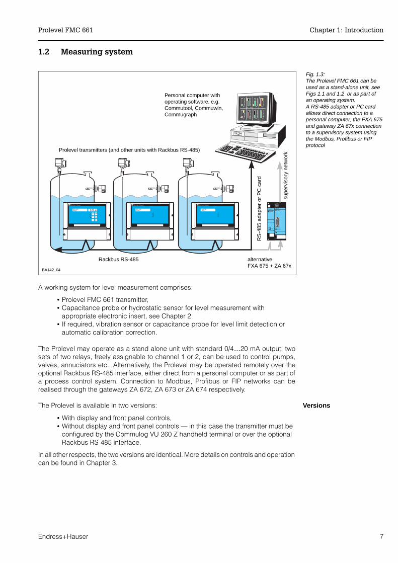
A working system for level measurement comprises:
• Prolevel FMC 661 transmitter,• Capacitance probe or hydrostatic sensor for level measurement with
appropriate electronic insert, see Chapter 2• If required, vibration sensor or capacitance probe for level limit detection or
automatic calibration correction.
The Prolevel may operate as a stand alone unit with standard 0/4…20 mA output; twosets of two relays, freely assignable to channel 1 or 2, can be used to control pumps,valves, annuciators etc.. Alternatively, the Prolevel may be operated remotely over theoptional Rackbus RS-485 interface, either direct from a personal computer or as part ofa process control system. Connection to Modbus, Profibus or FIP networks can berealised through the gateways ZA 672, ZA 673 or ZA 674 respectively.
VersionsThe Prolevel is available in two versions:
• With display and front panel controls,• Without display and front panel controls — in this case the transmitter must be
configured by the Commulog VU 260 Z handheld terminal or over the optionalRackbus RS-485 interface.
In all other respects, the two versions are identical. More details on controls and operationcan be found in Chapter 3.
Endress+Hauser
PROLEVELFMC671
1A1B2A2B3
Endress+Hauser
PROLEVELFMC671
1A1B2A2B3
Endress+Hauser
PROLEVELFMC671 123.4
1A1B2A2B3
HV
+
E_
ZA 673
RACKBUS
PROFIBUS
FXA 675
ON
12 RB/485
BA142_04
Prolevel transmitters (and other units with Rackbus RS-485)
Rackbus RS-485
Personal computer withoperating software, e.g.Commutool, Commuwin,Commugraph
alternativeFXA 675 + ZA 67x
supe
rvis
ory
netw
ork
RS
-485
ada
pter
or
PC
car
d
Fig. 1.3:The Prolevel FMC 661 can beused as a stand-alone unit, seeFigs 1.1 and 1.2 or as part ofan operating system. A RS-485 adapter or PC cardallows direct connection to apersonal computer, the FXA 675and gateway ZA 67x connectionto a supervisory system usingthe Modbus, Profibus or FIPprotocol
Prolevel FMC 661 Chapter 1: Introduction
Endress+Hauser 7
1.3 Measuring principle
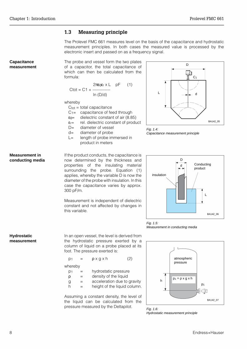
The Prolevel FMC 661 measures level on the basis of the capacitance and hydrostaticmeasurement principles. In both cases the measured value is processed by theelectronic insert and passed on as a frequency signal.
Capacitancemeasurement
The probe and vessel form the two platesof a capacitor, the total capacitance ofwhich can then be calculated from theformula:
2πε0εr x L pF (1) Ctot = C1 + -------------
ln (D/d)
wherebyCtot = total capacitanceC1= capacitance of feed throughε0= dielectric constant of air (8.85)εr= rel. dielectric constant of productD= diameter of vesseld= diameter of probeL= length of probe immersed in
product in meters
Measurement inconducting media
If the product conducts, the capacitance isnow determined by the thickness andproperties of the insulating materialsurrounding the probe. Equation (1)applies, whereby the variable D is now thediameter of the probe with insulation. In thiscase the capacitance varies by approx.300 pF/m.
Measurement is independent of dielectricconstant and not affected by changes inthis variable.
Hydrostaticmeasurement
In an open vessel, the level is derived fromthe hydrostatic pressure exerted by acolumn of liquid on a probe placed at itsfoot. The pressure exerted is:
p1 = ρ x g x h (2)
whereby p1 = hydrostatic pressureρ = density of the liquidg = acceleration due to gravityh = height of the liquid column.
Assuming a constant density, the level ofthe liquid can be calculated from thepressure measured by the Deltapilot.
C1
BA142_05
dL
D
Fig. 1.4:Capacitance measurement principle
BA142_06
d Conductingproduct
L
D
insulation
Fig. 1.5:Measurement in conducting media
BA142_07
p1 = ρ x g x hh
atmospheric pressure
p1
Fig. 1.6:Hydrostatic measurement principle
Chapter 1: Introduction Prolevel FMC 661
8 Endress+Hauser

1.4 Functional description
Fig. 1.7 is a block diagram of the Prolevel FMC 661. The transmitter supplies the powerto the sensor. The capacitance or pressure measured by the sensor is converted into afrequency signal by the electronic insert located in its head and transmitted to the Prolevelover a two-core cable. The signal is then processed to provide six operating modes.
Signal processingBy calibrating at two levels, »empty« and »full«, the frequency signal is converted to alevel measurement in the units entered during calibration. In mode 5, the measured valueat channel 1 is then corrected. For non-linear volume/level relationships, volume can becalculated from level via the vessel characteristic which describes the shape of thevessel. The signal resulting from the calibration and linearisation provides a standard0/4...20 mA output, proportional to level or volume. Any portion of the measuring rangecan be taken to provide a scaled output. The two sets of two relays can be assigned toeither measuring channel to provide level control by switching pumps on and off.
All measured values and the complete configuration can be accessed via the optionalRackbus RS-485 interface.
Fail-safe operationIf a fault condition is detected, e.g. a break in sensor - transmitter cable, the analoguesignal switches to -10 % or +110 % level or holds the last measured value. The alarmrelay de-energises and the red LED on the front panel lights. In addition, each set ofrelays can be set to switch on or off as required.
Hz
cap./press.
electronicinsert
analog
digital
current
sensitivity [Hz/pF]
offset [Hz]
offset [pF] sensitivity [pF/cm]
range upper limitV2
range lower limitV1
frequency volume
V2V1
level
volumeH2
H1
level
cap./press.
level
zero point shift
levellimitdetection
switch pointhysteresismin. / max. fail-safe modeswitching delay
frequency2
relay 1a, 1b
relay 2a, 2b
BA142_08
Channel 1
Channel 2
Fig. 1.7:Signal processing in theProlevel FMC 661 for singlechannel operation (leveland/or limit switching)
Mode in V8H0 Function
0 Simultaneous level measurement and limit detection on channels 1 and 2
1 Level measurement on channel 1 only
2 Limit detection on channel 2 only
5 Corrected level measurement — the level measurement at channel 1 iscorrected when the product covers the limit switch at channel 2
6 Simulation of level, volume or current at channel 1
7 Simulation of limit detection at channel 2
Table 1.1:Prolevel FMC 661 operatingmodes
Prolevel FMC 661 Chapter 1: Introduction
Endress+Hauser 9

1.5 Technical data
General specifications
Input characteristics
Output characteristics
Manufacturer: Endress+Hauser GmbH+Co.
Designation: Prolevel FMC 661
Function: Transmitter for level measurement with capacitance and hydrostaticprobes as well as level limit detection with capacitance and vibrationprobes
Input signal: Level proportional PFM signal
Interfaces: 0/4…20 mA, Rackbus RS 485 (option)
Reference conditions: to IEC 770 (TU = 25°C) or as specified
Miscellaneous: CE mark
Signal input, channel 1
Signal: Pulse frequency modulated signal from connected probe or sensor
Explosion protection: PTB [EEx ia] IIC, FM, CSA, intrinsically safe signal circuits separatedfrom each other and rest of the electronics
Probe or sensor: Multicap or other capacitance probe with EC 37 Z or EC 47 Zelectronic insertDeltapilot S hydrostatic sensor with FEB 17/FEB 17 P
Switch input, channel 2
Signal : Pulse frequency modulated signal from connected probe or sensor
Limit switch: Multicap probe with EC 16 Z or EC 17 Z electronic insertother capacitance probe with EC 17 Z electronic insertLiquiphant FDL 30 / FDL 31 / FDL 35 / FDL 36Soliphant DM 90 Z / DM 91 Z / DM 92 Z
Analog output
Output: 0... 20 mA, switchable to 4... 20 mASignal underflow: -2 mA;Signal overflow: + 22 ± 0.2 mA
Output on alarm: selectable +110%, -10% or hold
Current limitation: 23 mA
Temperaturecoefficient:
0.3%/10 K of range end value
RFI (E = 10 V/m) 1 %
Warm-up time: 1 s
Output damping: 0 to 100 s, selectable
Max. load: 600 Ω
Load effect: negligible
Relays
Type: 5 relays with potential-free changeover contacts
Function: 2 pairs of two limit relays with freely selectable switch points andhysteresis for operation in min. or max. fail-safe mode1 alarm relay (de-energises on fault condition)
Switching capacity: 6 A, 250 VAC ; 750 VA at cos ϕ = 0.7, 1500 VA at cos ϕ = 16 A, 250 VDC; 200 W
Chapter 1: Introduction Prolevel FMC 661
10 Endress+Hauser
Output characteristics(continued)
Power supply
Environment
Mechanicalspecifications
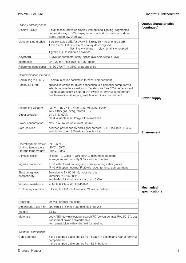
Display and keyboard
Display (LCD): 4 digit measured value display with optional lighting, segmentedcurrent display in 10% steps, various indicators (communication,signal underflow, overflow)
Light emitting diodes: 1 yellow status LED for every limit relay (lit = relay energised)1 red alarm LED, lit = alarm — relay de-energised;
flashing = warning — relay remains energised1 green LED to indicate power on
Keyboard: 6 keys for parameter entry, option available without keys
Interfaces: 0/4…20 mA, Rackbus RS 485 (option)
Reference conditions: to IEC 770 (TU = 25°C) or as specified
Communication interface
Commulog VU 260 Z: 2 communication sockets in terminal compartment
Rackbus RS 485 optional interface for direct connection to a personal computer viaadapter or interface card, or to Rackbus via FXA 675 interface cardRackbus address via 6-gang DIP-switch in terminal compartmentbus termination via 4-gang switch in terminal compartment
Alternating voltage:
Direct voltage:
230 V / 115 V / 110 V (85...253 V), 50/60 Hz or 24 V / 48 V (20...55V), 50/60 Hz or24 V (16...60V), residual ripple max. 2 Vpp within tolerance
Power consumption: max. 7 W, switch-on current 880 mA
Safe isolation: between power supply and signal outputs, CPU, Rackbus RS-485,switch-on current 880 mA and electronics
Operating temperature:Limiting temperature:Storage temperature:
0°C…60°C -20°C…60°C-40°C…80°C
Climatic class: to Table 10, Class R, DIN 40 040, instrument outdoors, average annual humidity 95%, dew permissible
Ingress protection: IP 66 with closed housing and corresponding cable glandsIP 40 with open housing, IP 20 with open terminal compartment
Electromagnetic compatibility:
Emission to EN 50 081-2, industrial useImmunity to EN 50 082-2 and NAMUR industrial standard, at 10 V/m
Vibration resistance: to Table 6, Class W, DIN 40 040
Explosion protection: [EEx ia] IIC, FM, CSA see also "Notes on Safety"
Housing: for wall- or post-mounting
Dimensions (l x b x h) 292 mm x 176 mm x 253 mm, see Fig. 2.3
Weight: 2.6 kg
Materials: body ABS (acrylnitrilbutadenestyrol)/PC (polycarbonate), RAL 5012 (blue)transparent cover, polycarbonatefront panel, blue with white field for labelling
Electrical connection
Cable entries: 5 pre-stamped cable entries Pg 16 each in bottom and rear of terminalcompartment4 pre-stamped cable entries Pg 13.5 in bottom
Prolevel FMC 661 Chapter 1: Introduction
Endress+Hauser 11

2 Installation
This Chapter describes:
• Probes and sensors for the Prolevel FMC 661• Installation of the Prolevel FMC 661• Transmitter wiring• Sensor connection.• Hardware configuration for Rackbus RS-485 option.
Fig 2.1 shows the structure of the chapter.
Technicians and fitters It is assumed that suitably qualified personnel are to be used for the installation andelectrical connection of the system components. This is particularly important when thesensors are to be installed in hazardous areas. Please note the following:
Warning!• The Prolevel FMC 661 transmitter must be installed outside explosion hazardous
areas. • Observe the specifications in the certificates as well as local regulations when
mounting the sensors in hazardous areas
Warning!
BA142_09
Mounting theProleveltransmitter
Wiring theProleveltransmitter
MeasuringsystemProbe constants
Wiring thesensors andprobes
Wiring andconfiguration forRackbus RS-485
2.1 2.2 2.3
2.4 2.5
Fig. 2.1:Structure of Chapter 2,
Installation
Chapter 2: Installation Prolevel FMC 661
12 Endress+Hauser

2.1 Probes and sensors
Table 2.1 lists the sensors most frequently used with the Prolevel FMC 661 transmitter.In addition to those listed, all probes which can be used with an EC 17 Z, EC 37 Z orEC 47 Z electronic insert can be connected to the transmitter. Installation hints can betaken from the appropriate Technical Information Sheet.
Sensor constantsDeltapilot S hydrostatic pressure sensors and EC 37 Z/47 Z inserts are supplied with thesensor constants zero frequency »fo« and sensitivity »∆f« or »S«, see Fig. 2.2. ForDeltapilot S sensors the constants depend on the measuring range, see Table 2.2. Notethese constants and enter them into fields V3H5 and V3H6 during commissioning,Section 4.1. This dispenses with the need for a recalibration of the transmitter onreplacement of the sensor or insert.
PrincipleChannel 1 Channel 2
Probe TI sheet Insert Probe TI sheet Insert
Capacitance DC 11 TI 169FDC 16 TI 096FDC 21 TI 208FDC 26 TI 209F11 322 Z E 11.81.0311 500 Z TI 161F21 211 E 10.73.18Multicap TE, TA, E, A
TI 239, 240, 242, 243
EC 37 ZEC 47 Z
DC 11 TI 169FDC 16 TI 096FDC 21 TI 208FDC 26 TI 209F11 450 (Z/St) TI 19711 961 (Z) E 04.77.0421 262 (Z/St) TI 22721 265 (Z/St) TI 195Multicap TE, TA, E, A
EC 17 ZEC 16 ZFEC 22
Hydrostaticpressure
Deltapilot S TI 257DB 50, 50 L, 51, 52, 53
FEB17FEB 17P
Not suitable
Vibration Not suitable Liquiphant DL 17 Z 013154-0008FDL 30/31/35/36 TI 185F
Soliphant DM 90 Z…92 Z TI 124F
BA042
EL 17 ZEM 17 Z
Table 2.1:Selection of probes suitable foruse with the Prolevel FMC 661
1 3 6542+ I
II
CA (pF) C(S)(pF)
17d4
d4 / z47
18d2
d2 / z28
FMC480ZFMC470ZFMC671 / 672 / 676 / 677ZHAA420Z
1MHz
EC 47 Z
Ex
0,6526,805S
I IIfo 475,3 57,2
EC10015EP8
BA142_10
sensor constants
Fig. 2.2:Location of sensor constants onEC 37 Z/47 Z electronic insertand Deltapilot S DB 4x housing
Cell type
Electronic insert FEB 17/FEB 17 P
Range f 0 ∆f Range f 0 ∆f
0.1 bar BA 0…100 mbar 200 10 DA -100…100 mbar 200 5
0.4 bar BB 0…400 mbar 200 2.5 DB -400…400 mbar 200 1.25
1.2 bar BC 0…1200 mbar 200 0.833 DC -900…1200 mbar 200 0.476
4.0 bar BD 0…4000 mbar 200 0.25 DD -900…4000 mbar 200 0.204
Table 2.2:Measuring ranges and sensorconstants of Deltapilot S DB 5x
Prolevel FMC 661 Chapter 2: Installation
Endress+Hauser 13

2.2 Prolevel FMC 661 installation
Location Where possible, find a shady, protected spot in which to mount the Prolevel transmitter:
• Nominal operating temperature: 0°C…+60°C
Use a protective hood or provide cooling if the ambient temperature exceeds +60°C. Fortemperatures below -20°C insulate the instrument.
Mounting The Prolevel FMC 661, with IP 66 protective housing, can be mounted on a wall or postoutdoors or in the control room. Fig. 2.3 gives details for wall mounting.
Fig. 2.4 shows how the Prolevel can bepost-mounted with the all-weather cover.The fastenings (nuts and bolts) for bothpost mounting and all-weather cover aresupplied with the units.
• Post mounting:Material: galvanised steel (for 2" post Order No. 919 566-0000; for 1" post: 919 566-1000); stainless steel 1.4301 (≅ SS 304 H)(for 2" post Order No. 919 566-0001; for 1" post: 919 566-1001); Weight: 1 kg
• Prolevel all-weather cover:Material: Aluminium, blue paint-finish;Order No. 919567-000Material: Steel 1.4301 (≅SS 304 H),blue paint-finish; Order No. 919567-001
BA142_11
292
min. 52106
253
275.5
gapmin. 69
201
ø 4.5
Fig. 2.3:Dimensions in mm of Prolevel
FMC 661 housing1" = 25.4 mm
BA142_12
Fig. 2.4:Post-mounting with all-weather cover
Chapter 2: Installation Prolevel FMC 661
14 Endress+Hauser

2.3 Transmitter wiring
Warning!• Make electrical connections with the power supply switched off! • The PE terminal strip must be grounded externally (contact protection)!• When wiring up probes and sensors in explosion hazardous areas, observe the
instructions on the certificate and other local regulations.
Terminal stripThe terminal strip for cable diameters up to 2.5 mm2 is located in a separate connectioncompartment. Fig. 2.5 shows the wiring diagram for the Prolevel FMC 661 (Terminal 3 isreserved for the internal protective ground):
• Remove the plastic cover from the front of the connection compartment • Press out the pre-stamped cable entries as required
bottom: 5 x Pg 16, 4 x Pg 13.5; rear: 4 x Pg 16.
PowerThe power requirements are printed on the nameplate at the right-hand side of thenameplate, see also Section 1.5, "Technical Data".
• If the specifications on the nameplate do not correspond to those of yourpower supply, do not connect up - you may damage the instrument!
• Connect the protective ground to the metallic terminal strip provided at the left— this ensures safe isolation and contact protection.
• Current output, relay outputs, power connection and sensor input are allelectrically isolated from one another.
Analogue outputs Only one non-floating device can be connected to the current output.
• There is no limit to the number of floating devices, other than that imposed byconsiderations of the maximum load of 600 Ω.
RelaysFor the switching capacity of the relays see the technical data in Section 1.5.
• Relays 1a and 1b are normally assigned to channel 1• Relays 2a and 2b are normally assigned to channel 2.
The assignment can be changed by software, see Section 4.4.
RS-485 [EEx ia] IICB DGND A
L+ L-L1 N
L+ L-16
...60
VD
C85
...25
3 VA
C20
...55
VA
C
L1 N PE
0/4.
..20
mA
Sen
sor 1
Sen
sor 2R
xD/T
xD-P
RxD
/TxD
-ND
GN
DR
S-4
85
1 2 3 4 5 81 82 91 923111 21 41
1b1a 2a 2b
51 613212 22 42 52 623313 23 43 53 60
- + - +
BA142_13
curr
ent 1
rela
ys c
hann
el 1
rela
ys c
hann
el 2
alar
m r
elay
PE
term
inal
str
ipgr
ound
ext
erna
lly
optio
nal i
nter
face
leve
l sen
sor
limit
switc
h
Com
mul
og V
U 2
60Z
bus
switc
hes
Fig. 2.5:Terminal assignments forProlevel FMC 661
Warning!
Prolevel FMC 661 Chapter 2: Installation
Endress+Hauser 15

2.4 Sensor connection
Sensor cable Use commercial 2-core installation cable, max. line resistance 25 Ω/core, for the sensor/transmitter cable — the Prolevel satisfies the quoted EMC standards with this cable.
Level probes andsensors, channel 1
The Prolevel FMC 661 can be operated with a variety of sensor types, each requiring adifferent electronic insert. For Channel 1, continuous level measurement:
• EC 37 Z or EC 47 Z for capacitance and Multicap probesEB 17 or EB 27 P for Deltapilots S
Level limit switch,channel 2:
The level limit switch may be a vibration probe — Liquiphant (liquids) or Soliphant (solids)— or a capacitance probe, with electronic insert
• EC 16 Z/EC 17 Z for Multicap probes EC 17 Z for other capacitance probes
• EL 17 Z for Liquiphant probesEM 17 Z for Soliphant probes
EC 37 Z and EC 47 Z The electronic inserts EC 37 Z and EC 47 Z have two measuring ranges which can beselected by inserting a bridge between terminals 4 and 5 of the insert, see Fig 2.6. Fullinstructions on selection of the insert are to be found in Publication E 07.80.06/1c.
• Note the zero frequency fo____ and sensitivity S_____on the insert for therange you have selected.
EC 17 Z The EC 17 Z electronic insert can be used at Channel 2 with capacitance and Multicapprobes for limit level switching. The connection diagram is shown in Fig. 2.6. Technicalinformation is given in Publication E 11.84.04/1a.
EC 16 Z The EC 16 Z electronic insert is for use on channel 2 with the Multicap probes with activebuild-up compensation. Wire it up as described in the Technical Information SheetTI 170F delivered with the insert.
81 82
BA142_14
Channel 1
Insert bridge for Range II (standard) Remove for Range I
Groundconnection
Fig. 2.6:Connection diagram for
electronic insertsLeft: Capacitance/Multicap
EC 37 Z/EC 47 ZRight: Capacitance/Multicap
EC 17 Z
91 92 Insert bridge ifconductivebuild-up on probe
Channel 2
Groundconnection
Insert bridge(see instructions)
BA142_15
Chapter 2: Installation Prolevel FMC 661
16 Endress+Hauser

FEB 17 and FEB 17 PThe FEB 17/FEB 17 P electronic insert canbe used at Channel 1 with Deltapilot SDB 5x… sensors to measure level andvolume in open vessels. The sensorconstants are listed in Tabel 2.2.
• Note the zero frequency fo_____ andsensitivity ∆f _____ of the probe
EL 17 Z and EM 17 ZThe EL 17 Z electronic inserts can be usedat Channel 2 with Liquiphant sensors forlimit level switching. For Soliphant sensorsthe EM 17 Z insert is used. Publications013154-0008 and BA 042 (014897-0002)contain full installation instructions.
81 82
FEB 17/FEB 17 P
1 2 3 4
BA142_56
Channel 1
Fig. 2.7:Connection diagram for Deltapilot S withFEB 17/FEB 17 P electronic insert
91 92
BA142_16
Channel 2
Fig. 2.8:Connection diagram for Liquiphant/Soliphantelectronic inserts EL 17 Z/EM 17 Z
Prolevel FMC 661 Chapter 2: Installation
Endress+Hauser 17
2.5 Rackbus RS-485 option
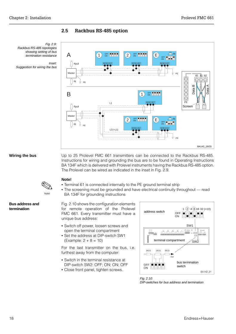
Wiring the bus Up to 25 Prolevel FMC 661 transmitters can be connected to the Rackbus RS-485.Instructions for wiring and grounding the bus are to be found in Operating InstructionsBA 134F which is delivered with Prolevel instruments having the Rackbus RS-485 option.The Prolevel can be wired as indicated in the inset in Fig. 2.9.
Note!• Terminal 61 is connected internally to the PE ground terminal strip• The screening must be grounded and have electrical continuity throughout — read
BA 134F for grounding instructions
Bus address andtermination
Fig. 2.10 shows the configuration elementsfor remote operation of the ProlevelFMC 661. Every transmitter must have aunique bus address:
• Switch off power, loosen screws andopen the terminal compartment
• Set the address at DIP-switch SW1(Example: 2 + 8 = 10)
For the last transmitter on the bus, i.e.furthest away from the computer:
• Switch in the terminal resistance atDIP-switch SW2: OFF; ON; ON; OFF
• Close front panel, tighten screws.
A
L1
L2 (> L1)
Master
Rpull
Rt
Master
Rpull
Rt
1 OFFON
60 61 62
2 EOFFON
OFFON
60 61 6260 61 62
1 OFFON
60 61 62
2 EOFFON
OFFON
60 61 6260 6162
B
PE
PE
Rt150Ω
Rt150Ω
PE
PE
BA142_19/20
Fig. 2.9:Rackbus RS-485 topologies
showing setting of bustermination resistance
Inset:Suggestion for wiring the bus
SW1
1 2 4 8 16 32
150 Ω 392 Ω392Ω
+5V
(=10)
ONOFF
ONOFF
RS-485 [EEx ia] IICB DGND A
L+ L-L1 N 1b1a 2a 2b
- + - +
SW2
BA142_21
bus terminationswitch
address switch
terminal compartment
Fig. 2.10:DIP-switches for bus address and termination
61
PE
60 62
Dat
a B
Dat
a A
Screen
Note!
Chapter 2: Installation Prolevel FMC 661
18 Endress+Hauser

3 Controls
This Chapter describes how the Prolevel FMC 661 transmitter is operated. It is dividedinto the following sections:
• Operating matrix• Keyboard and display• Commulog VU 260 Z handheld terminal• Rackbus RS-485.
3.1 Operating matrix
All functions, including the analogue outputs and relay switch points are configured viathe operating matrix, see Figs 3.1 and 3.2:
• Each field in the matrix is accessed by a vertical (V) and horizontal (H)position which can be entered at the front panel of the Prolevel FMC 661, bythe Commulog VU 260 Z or for the Rackbus RS-485 from a personal computer.
A matrix card, reproduced at the back of this manual, is delivered with the ProlevelFMC 661 transmitter.
Prolevel FMC 661 display
Parameter at current matrixposition
Pressed togetherMove to V0H0
Move H0 …H9, H0 Move V0…V9, V0
BA142_22
Current matrix position
Fig. 3.1:Prolevel FMC 661Parameter matrix operation withfunction of V and H keys.The complete matrix has 10 x 10fields, although not all are used
Diagnostics key - pressto display errormessage when iconblinks
Escape key - press tomove to field 00
Entry key - press to callor quit parameter entryMatrix selection keys -
press to move about matrix BA142_23
Commulog display
Parameter
Bar chart of analogue signal
Fig. 3.2:Commulog VU 260 Z display andkey functions
The Tag No. and measurementunits are entered in the VA levelwhich can be accessed by theCommulog or via the RackbusRS-485 interface only
Prolevel FMC 661 Chapter 3: Controls
Endress+Hauser 19

3.2 Keyboard and display
Fig. 3.1 shows the LC-display with matrix of the Prolevel FMC 661, Fig. 3.3 its front panel.Table 3.1 below describes the function of the operating keys.
• Changes are not possible if the matrix has been locked (Section 4.6). • Non-flashing parameters are either read-only indications or locked entry fields.
Endress+Hauser
PROLEVELFMC 671 123.4
1A1B2A2B3
HV
+
E_
VH0 0
Measured value display
4 yellow limit relay LEDs• lit, relay energised
Parameter entry keysRed alarm relay LED• Lights on fault condition,
relay de-energises• Flashes on warning
relay remains energised
Matrix selection keys
Communications indicator
Matrix position indicator
BA142_24
10-step segmented displayshowing percentage 0/4 …20 mA signal
Current underflow/overflowindicator
Green operational LED• Lights in normal operation
Fig. 3.3:Front panel of the
Prolevel FMC 661 transmitter
The transmitter is also availablewithout the keyboard
Keys Function
Matrix selection
• Press V to select the vertical position.
• Press H to select the horizontal position
• Press simultaneously to select the measured value field, V0H0
Parameter entry
• Select the digit to be changed. The digit at the extreme left is selected and flashes.
• Move to the next digit by pressing »⇒« again. When the last digitis reached »⇒« selects the leftmost digit again.
• To change the position of the decimal point, press down both »⇒« and »+«. The decimal point moves 1 space to the right.
• Increases the value of the flashing digit
• Decreases the value of the flashing digit• To enter a negative number decrease the leftmost digit until a
minus sign appears in front of it
• Press »E« to register entry. • Unregistered entries remain ineffective and the instrument will
operate with the old value.
+
+
Table 3.1:Prolevel FMC 661
Parameter entry and display keys
Chapter 3: Controls Prolevel FMC 661
20 Endress+Hauser

3.3 Commulog VU 260 Z
The Prolevel FMC 661 without keyboard can be configured with the Commulog VU 260 Zhandheld terminal, Figs 3.2 and 3.4. A full description of Commulog operation is to befound in Operation Instructions BA 028. Table 3.2 summarizes the key functions.
Warning!• The power and relay terminals in the terminal compartment are live!.
RS-485
B DGND A
L+ L-L1 N 1b1a 2a 2b
- + - +
FMC 671 Z
Warning! Warning!
BA142_25
Measured value andsegmented current display
Function keys
Matrix selectionkeys
Warning!power and relay terminalsare live!
Commulog sockets
terminal compartment
Fig. 3.4:Configuration with handheldterminal Commulog VU 260 Z
The Prolevel FMC 661 appearsas device FMC 671 Z
Keys Function
Matrix selection
• Select matrix position
• »Escape key«, selects the position V0H0
• Displays error message if diagnostics icon flashes• Press »Escape« to reset fault alarm and return to last position
Parameter entry
• Calls the parameter entry mode• Quits parameter entry mode and registers the entered value
• Select the digit to be changed: the selected digit flashes.
• Enter the desired value: If the parameter is alphanumeric:- The ⇑ key scans through all characters starting from
"-" through: 0,1,..,9,.,/,+, space, Z,Y,X,W,..- The ⇓ key scans through all characters starting from
"-" through: A,B,..,Y,Z, space,+,/,.,9,8,...
• Move the decimal point:- ⇐ and ⇑ together to move left or- ⇒ and ⇑ together to move right.
• Restores original value and quits entry mode.The Commulog stays at the selected matrix field.
+
+
Table 3.2:Prolevel FMC 661Parameter entry and displaykeys for Commulog VU 260 Z
Warning!
Prolevel FMC 661 Chapter 3: Controls
Endress+Hauser 21

3.4 Rackbus RS-485 (option)
Prolevel FMC 661 transmitters with Rackbus RS-485 interface can be configured from apersonal computer using one of the Endress+Hauser operating programs:
• Fieldmanager 485 Version 5.0 and Commugraph 485 if connected to thecomputer via a RS-485/RS-232C converter or RS-485 card.
• Commuwin, Commutec operating program, Commutool if connected via theFXA 675 and gateway ZA 67x.
The operation corresponds to that of the keyboard version. Full details of the programscan be taken from, e.g. Operating Instructions BA 134F, which is delivered with allProlevel transmitters with Rackbus RS-485 interface.
Note!• The Prolevel appears in all programs with the designation "FMC 671 Z"
H0 H1 H2 H3 H4V0V1V2V3V4
H5 H6 H7 H8 H9
V5V6V7V8V9VA
V0H2
7.00full calibration 7.00 m
Selection of horizontalposition H0 …H9
Selection of vertical position V0…VA
BA142_26
parameter entry
4 x 5 field portion ofmatrix scrolled onmonitor
Fig. 3.5:Parameter entry in configuration
software
Note!
Chapter 3: Controls Prolevel FMC 661
22 Endress+Hauser

4 Level Measurement
This chapter is concerned with the level measurement functions (operating mode 1 inV8H0, default) of the Prolevel FMC 661; the principle sections describe:
• Commissioning• Calibration: — for upright cylindrical tanks
— for horizontal cylindrical tanks— for tanks with conical outlet— dry calibration for hydrostatic sensors
• Analogue outputs• Relays• Display of measured values• Locking the parameter matrix.
With the exception of the dry calibration, the configuration procedure is independent ofwhether a hydrostatic pressure sensor or capacitance probe is connected to the Prolevel.
4.1 Commissioning
When programming the Prolevel for the first time, reset the module to the factory basedparameters, see Table in back cover. Then enter the probe constants fo and S (∆f) —measured at 25°C. This ensures that the EC 37 Z/EC 47 Z electronic insert or Deltapilotcan be replaced without the need for recalibration, see Section 6.4.
Step Matrix Entry Significance1 V9H5 e.g. 671 Enter any number 670…679 to reset transmitter2 - »E« Register entry
3 V3H5 e.g. 475.3 Enter zero frequency fo (offset) of electronic insert or sensor4 - »E« Register entry
5 V3H6 e.g. 6.805 Enter sensitivity, S or ∆f, of electronic insert or sensor6 - »E« Register entry
V0H0
fo, S/ f
BA142_27
Measuredvalues
Standardcalibration
Analogue output
RelaysParameterlock
4.1
4.2
4.3
4.4 4.5
Calibrationhorizontalcylinder
Calibrationconicaltank
"Dry"calibrationρgh
Sensorconstants
4.6
Fig. 4.1:Procedure: calibration andoperation for level measurement
Prolevel FMC 661 Chapter 4: Level Measurement
Endress+Hauser 23

4.2 Calibration
This section describes three methods of calibration which require the tank or silo to befilled and the entry of:
• an »empty« level at V0H1 and• a »full« level at V0H2.
The fourth method can be used to make a »dry« calibration for hydrostatic sensors. Forhorizontal cylinders and tanks with conical outlet, users requiring a volume or weightmeasurement can activate the linearisation procedure.
Note!• Prolevel is not bound to specific level units: during calibration it merely assigns the
numbers entered to the measured frequencies for »empty« and »full«.
1) Standard calibrationfor upright cylinders # Matrix Entry Remarks
1 V0H1 E Tank empty, currentlevel in your units
2 - »E« Register entry
3 V0H2 F Tank full, currentlevel in your units
4 - »E« Register entry
5 V0H0 Level Measured value inthe units selected.
Note!• The calibration can be performed in
reverse order.• For bulk solids (capacitance probes!),
the probe measures the depth ofemersion in the product only. Accountfor any filling mound or outflowdepression by the entered levels.
• Density correction, see p. 29.
After calibration If the product level is entered in %:
• % level is displayed at V0H0• the 0/4…20 mA signal range
corresponds to 0…100% level• relays 1a and 1b switch at 90% in
maximum fail-safe mode.
Next step … If the level is entered in length, volume orweight units, the analogue output andrelays must be set, see p. 30…33.
Note!
V0H1
V0H2
»Empty« level E(0…40%)
Deltapilot
capacitance probe
»Full« level F(60…100%)
BA142_28
probe or sensorcovered
Fig. 4.2:Parameters for standard calibration
Note!
Chapter 4: Level Measurement Prolevel FMC 661
24 Endress+Hauser

2) Calibration for horizontal cylinders# Matrix Entry Remarks
1 V0H1 E Tank empty, currentlevel in %, m, ft
2 - »E« Register entry
3 V0H2 F Tank full, currentlevel in %, m, ft
4 - »E« Register entry
After calibration the level can be read off atV0H0 in %, ft or m.
Linearisation, horizontalcylinder
A volume measurement can be made bycalling the linearisation table for horizontalcylinders. Two parameters are entered:
• Tank diameter, D• Tank volume, V.
# Matrix Entry Remarks5 V2H7 D Tank diameter,
%, m or ft6 - »E« Register entry
7 V2H8 V Tank volume*,hl, gal…
8 - »E« Register entry
9 V2H0 1 Activate linearisation10 - »E« Register entry
* If V =100 is entered, % volume is measured
OffsetThe linearisation starts at the tank bottom.If the zero point of the calibration does notstart at the same point you must now entera negative offset in the units of calibration.
# Matrix Entry Remarks1. V3H4 –OFF Offset, m or ft2 - »E« Register entry
After linearisation• Volume is displayed at V0H0• Level is displayed at V0H9• Density correction, p. 29.
Next step …Set analogue output and relays in volumeunits, see p. 30…33.
Note!• For linearisation volume => level,
see Appendix, p 46.
V0H1
V0H2
D (V2H7)
E = 0?OFF (V3H4)
V (V2H8)
»Empty« level E(0…40%)
»Full« level F(60…100%)
BA142_29
probe or sensor covered
100%
100% for entries in %
0% for entries in %
0%
100%
Zero point for linearisation
Emptycalibration E
Fig. 4.3:Parameters for calibration and linearisation in ahorizontal cylinder
Level %: refer E% and F% to thebottom (0%) and the top (100%)of the tank! D is then 100%
Note!
Prolevel FMC 661 Chapter 4: Level Measurement
Endress+Hauser 25

3) Calibration for tankswith conical outlet # Matrix Entry Remarks
1 V0H1 E Tank empty, currentlevel in %, m, ft
2 - »E« Register entry
3 V0H2 F Tank full, currentlevel in %, m, ft
4 - »E« Register entry
After calibration the level can be read off atV0H0 in %, m, or ft. Volume or weight canbe measured after a) manual or b) semi-automatic entry of a linearisation table.
a) Linearisation, manual You require a linearisation table, H/V orH/G, max. 30 pairs in increasing order
• Level H in %, m or ft• Volume V or weight G in customer units.
# Matrix Entry Remarks5 V2H1 0 Manual6 - »E« Register entry
7 V2H2 1 Table no.8 - »E« Register entry
9 V2H3 V/G1…30 Volume/weight*10 - »E« Register entry
11 V2H4 H1…30 Level m or ft*12 - »E« Register entry
13 V2H5 »E« Next table no.*— springs to V2H3
*Repeat # 9…13 until all values entered
13 V2H0 3 Activate "manual"14 - »E« Register entry
Note!• First pair ~ 0 % level, in %, m, ft.
last pair ~ 100 % level, in %, m, ft. • On error E602 or E604, correct table.
Re-activate linearisation in V2H0.• For linearisation volume => level,
see Appendix, p. 47.
After linearisation • Volume/weight is displayed at V0H0• Level is displayed at V0H9• Density correction, p. 29.
Next step … Set analogue output and relays in volumeor weight units, p. 30…33.
Note!
123
45
67
8
H
V/G
V0H1
V0H2
V2H0...V2H5
BA142_30
»Empty« level E(0…40%)
»Full« level F(60…100%)
probe or sensorcovered
V2H4H1
H2…H30
V2H3V/G1
V/G2…V/G30
0% = start of linearisation
Fig. 4.4:Parameters for calibration and linearisation in a tankwith conical outlet
Chapter 4: Level Measurement Prolevel FMC 661
26 Endress+Hauser

b) Semi-automatic linearisation
After calibration, p. 26, the semi-automaticlinearisation can be made:
• Enter known volume V/weight G in V2H3• Level is displayed in V2H4
No. Matrix Entry Remarks5 V2H1 1 Semi-automatic6 - »E« Register entry
7 V2H2 1 Table no.8 - »E« Register entry
9 V2H3 V/G1…30 Volume/weight*10 - »E« Register entry
11 V2H4 »E« Register level H1…30*
12 V2H5 »E« Next table no.*— springs to V2H3
*Repeat # 9…12 until all values entered
13 V2H0 3 Activate "manual"14 - »E« Register entry
Note!• On error E602 or E604, correct table. Re-activate linearisation in V2H0.
After linearisation• Volume/weight is displayed at V0H0• Level is displayed at V0H9• Density correction, p. 29.
Next step …Set analogue output and relays in volume or weight units, p. 30…33.
Deletion of value pairsTo delete a pair of values:
• Enter table number in V2H2• Enter 9999 in V2H3 or V2H4
Deletion of linearisationThere are two possibilities for deleting alinearisation:
• Enter "0" in V2H0: The linearisation isde-activated but the table remainsstored— Enter 1 (horizontal cylinder) or 3 (linearisation table) to re-activate.
• Enter "4" in V2H0: the manual orsemi-automatic linearisation is deleted,V2H0 = 0— The linearisation for horizontalcylinders is deactivated but remainsstored.
Note!
V2H0...V2H5
BA142_31
probe or sensorcovered
»Empty« level E
»Full« level F
volumemeasurement
0% = start of linearisation
Fig. 4.5:Parameters for calibration and semi-automaticlinearisation in a tank with conical outlet
H1H2H3......Hn
V1V2V3......Vn
H1H2H3......Hn
V1V2V3......Vn
H1H2H3......Hn
V1V2V3......Vn
V2H0 = 0
V2H0 = 1, 3
V2H0 = 4
BA142_32
Fig. 4.6:De-activating a linearisation
Prolevel FMC 661 Chapter 4: Level Measurement
Endress+Hauser 27

4) » Dry calibration« A dry calibration for hydrostatic sensors requires:
• the »empty« level at which the measurement should start• the maximum height of the liquid column at »full« level and• the density of the liquid• the calculated offset and sensitivity of the display.
Caution!• The sensor constants must have been entered as per Section 4.1.• Check the calibration during the first filling of the tank! If your calculations are
incorrect the levels measured will be incorrect also!
Example: display in %display for p zero = 0
Calculate the pressure in mbar acting atthe sensor for the desired »empty« leveland the span (»full« - »empty«):
pmbar = 10 x ρ (kg/dm3) x g (m/s2) x ∆h (m)
For 0.45 m water, display = 0%, For 10.45 m water, display = 100%Span (0%…100%) = 10 m
• pzero = 10 x 1.0 x 9.807 x 0.45= 44.13 mbar
pspan = 10 x 1.0 x 9.807 x 10.00 = 980.7 mbar
• Offset = pzero = 44.13 mbarSensitivity = pspan/span = 980.7/100
9.807 mbar/%
Sensor calibration# Matrix Entry Remarks1 V0H2 e.g. 100 Full level (100%)2 - »E« Register entry
3 V3H1 e.g. 44.13 Offset in mbar4 - »E« Register entry
5 V3H2 e.g. 9.807 Sensitivity mbar/%6 - »E« Register entry
7 V0H0 **.** Measured value %
The Prolevel now measures 0 at 44.13 mbar
Next step … Set analogue outputs and relays in %, seep. 30…33.
Caution!
sensor zero, f0 frequency (V3H5)
f (Hz)
P mbarlevel
BA142_33
offsetV3H1
disp
lay
sens
itivi
tym
bar/
digi
t, V
3H2
sensor sensitivity ∆f, S(V3H2)
Fig. 4.7:Offset and sensitivities for dry calibration
VH0 0
VH0 0
100
0 »Empty«, e.g. 0.45 m
»Full« e.g. 10.45 m
pempty = ρ x g x 0.45e.g. = 44.13 mbar
span
= 1
00%
= e
.g. 1
0 m
BA142_34
sensor zeropoint
display
sensoroffset
Fig. 4.8:Parameters for dry calibration, display in %
ρgh
Chapter 4: Level Measurement Prolevel FMC 661
28 Endress+Hauser

Example: display in hldisplay for p zero ≠ 0
Calculate the pressure in mbar acting at the sensor for the desired »empty« level andthe span (»full« - »empty«):
pmbar = 10 x ρ (kg/dm3) x g (m/s2) x ∆h (m)
For 0.0 m water, display = 50 hlFor 10.0 m water, display = 2000 hlSpan (50…2000 = 1950) = 10 m
• pzero = 10 x 1.0 x 9.807 x 0.0 = 0.0 mbarp1950 = pspan = 10 x 1.0 x 9.807 x 10.00 = 980.7 mbar
• Offset = pzero = = 0.0 mbarSensitivity = pspan/span = 980.7/1950 = 0.5029 mbar/hl
Sensor calibration# Matrix Entry Remarks1 V0H2 e.g. 2000 Full level (100%)2 - »E« Register entry
3 V3H1 0.0 Offset in mbar4 - »E« Register entry
5 V3H2 e.g. .5029 Sensitivity mbar/hl6 - »E« Register entry
The Prolevel now measures 0 at 0 mbar — anegative level offset must be entered, p. 25
7 V3H4 e.g. -50 Level offset8 - »E« Register entry
Next step …Set analogue outputs and relays in the units used for calibration, e.g. hl, see p. 30…33.
Density correction forhydrostatic sensor
If the product changes after calibration, the measurement can be corrected by enteringa density factor at V8H7:
Factor = old factor x new densityold density
The measured value is divided by the factor before display.
Note!• For an automatic density correction using an additional external limit switch see
»Calibration Correction« in Chapter 5
Note!
VH0 0
VH0 050
2000
»Empty« = 0.0 m
»Full« e.g. 10 m
pempty = ρ x g x 0.0e.g. = 0 mbar
span
= 2
000
- 50
= 1
950
=
e.g.
10
m
BA142_35
negative level offsetsensor zeropoint
display
Fig. 4.9:Parameters for dry calibration, display in hl
Prolevel FMC 661 Chapter 4: Level Measurement
Endress+Hauser 29
4.3 Analogue Outputs
This section describes the setting of the analogue outputs. The following parameters canbe entered or changed:
• Analogue signal range• Output damping• Value for 0/4 mA and 20 mA• Output at fault
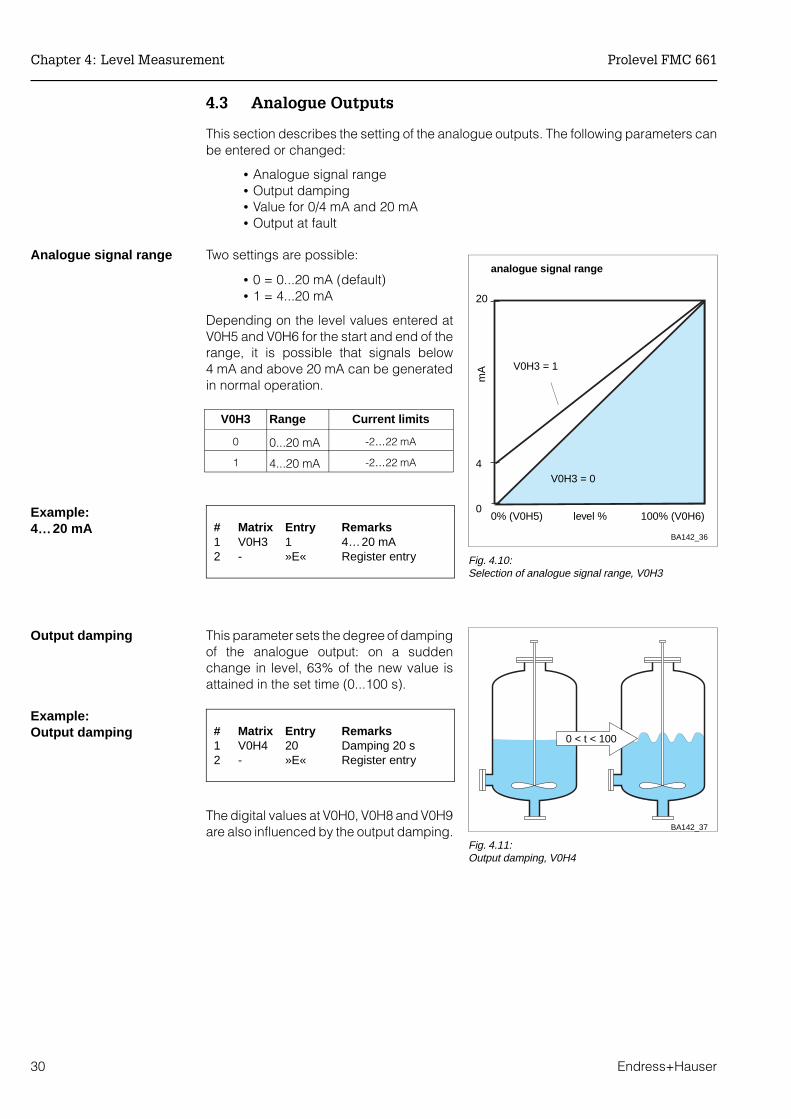
Analogue signal range Two settings are possible:
• 0 = 0...20 mA (default)• 1 = 4...20 mA
Depending on the level values entered atV0H5 and V0H6 for the start and end of therange, it is possible that signals below4 mA and above 20 mA can be generatedin normal operation.
V0H3 Range Current limits
0 0...20 mA -2…22 mA
1 4...20 mA -2…22 mA
Example:4…20 mA # Matrix Entry Remarks
1 V0H3 1 4…20 mA2 - »E« Register entry
Output damping This parameter sets the degree of dampingof the analogue output: on a suddenchange in level, 63% of the new value isattained in the set time (0...100 s).
Example:Output damping # Matrix Entry Remarks
1 V0H4 20 Damping 20 s2 - »E« Register entry
The digital values at V0H0, V0H8 and V0H9are also influenced by the output damping.
100% (V0H6)0% (V0H5)0
20
level %
BA142_36
analogue signal range
4
mA
V0H3 = 0
V0H3 = 1
Fig. 4.10:Selection of analogue signal range, V0H3
0 < t < 100
BA142_37
Fig. 4.11:Output damping, V0H4
Chapter 4: Level Measurement Prolevel FMC 661
30 Endress+Hauser
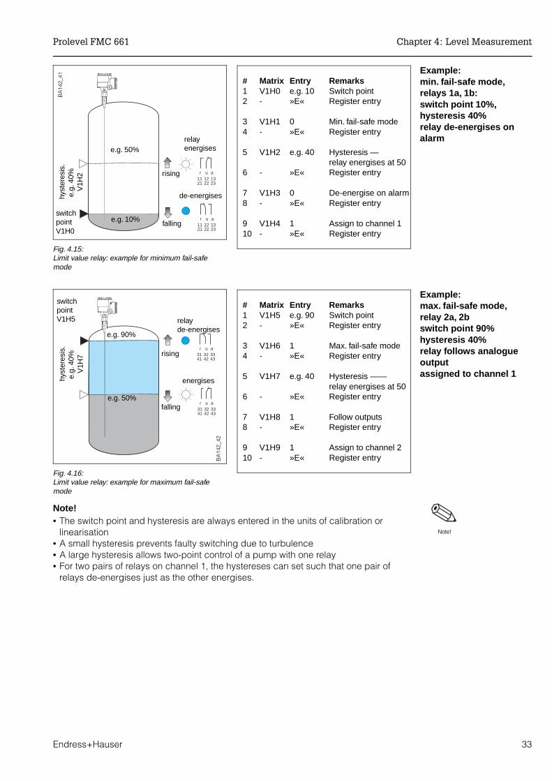
Value for 4 mA and 20 mA
The 4mA (V0H5) and 20 mA (V0H6) values,default values 0% and 100%, determinethe levels at which the analogue signalrange begins and ends.
Example:4 mA = 20%, 20 mA = 80%
# Matrix Entry Remarks1 V0H5 20 4mA value, 20 %2 - »E« Register entry
3 V0H6 80 20 mA value, 80%4 - »E« Register entry
Note!• Set in calibration/linearisation units• When V0H3 = 0, V0H5 = 0 mA value
Output on alarmThe analogue output can be set such thatit takes on distinctive values when a faultwith alarm is detected. Depending on thesetting in V1H3/V1H8, the relays may alsofollow the analogue output. The entry ismade in V0H7:
• 0 = -10% of signal range• 1 = +110% of signal range (default)• 2 = last value is held
Example:Output -10 % on alarm# Matrix Entry Remarks
1 V0H7 0 -10% on alarm2 - »E« Register entry
The current values set on an alarm areshown in the table
V0H3 =Current on alarm when V0H7 =
0: (-10%) 1: (+110%) 2: hold
0: 0…20 mA ≤ -2 mA ≥ 22.0 mA last value
1: 4…20 mA ≤ -2 mA ≥ 22.0 mA last value
Caution!• If setting 2 is chosen, the fault recognition system on the 0/4…20 mA signal line is
effectively deactivated. Although the transmitter recognises a fault, i.e. the alarmrelay de-energises and the associated LED lights, the signal output to any follow-upinstrumentation appears to indicate a correct measured value.
0%
100%
V0H5
V0H6
leve
l
0/4 mA 20 mA
BA142_38
Fig. 4.12:Value for 4 mA and 20 mA, V0H5 and V0H6
t
-2
4
0
2220
V0H71 = +110%
2 = hold value
mA
BA142_39
0 = -10%
alarm
Fig. 4.13:Output on alarm, V0H7
Note!
Caution!
Prolevel FMC 661 Chapter 4: Level Measurement
Endress+Hauser 31

4.4 Relays
Operating modes The Prolevel FMC 661 has five independent relays with potential-free changeovercontacts. Relays 1a, 1b, 2a and 2b are limit relays, relay 3 is an alarm relay which alwaysde-energises on fault condition. Relays 1a and 1b are set together, as are 2a and 2b. Five parameters set the limit relays, Table 4.1 summarises their function:
Relay on alarm The limit relays respond to an alarm according to the entry at V1H3/V1H8 (0 =de-energise, 1 = as Table 4.2). When the relays are assigned to the external limit switch(see Chapter 5) they always de-energises on alarm.
r u a r u a r u a3 51 52 53 51 52 53 51 52 53
11 12 13 21 22 2331 32 3341 42 43
11 12 13 21 22 2331 32 3341 42 43
11 12 13 21 22 2331 32 3341 42 43
1a1b2a2b
r u a r u a r u a
power failure: de-energised
Limit relays 1a, 1b , 2a, 2byellow LEDs
Alarm relay 3red LED
faultnormal operationBA142_40
normal operation
power failure: de-energised
Fig. 4.14:Relay LEDs as a function of relay
status:limit relay: lit, energised
out, de-energisedalarm relay (default setting):
lit, de-energisedout, energised
Parameter Matrix position forrelays
Entry/Function
1a, 1b 2a, 2b
Switch point V1H0 V1H5 Relay switch point in calibration/linearisation units
Fail-safe mode V1H1 V1H6 0: minimum fail-safe mode: — the relayde-energises when the level drops below theswitch point, see Fig. 4.15.
1: maximum fail-safe mode — the relayde-energises when the level rises above theswitch point, see Fig 4.16.
Hysteresis V1H2 V1H7 Range at end of which the relay energises again
Relay on alarm V1H3 V1H8 0: de-energised1: as analogue output: see Table 4.2.
Relay assignment V1H4 V1H9 1: channel 12: channel 2
Table 4.1:Parameters for setting limit relays
Setting at V0H7 Minimum fail-safe mode Maximum fail-safe mode
0 = -10% (≤ -2 mA) Relay de-energises Relay energises
1 = +110% (≥ +22 mA) Relay energises Relay de-energises
Table 4.2:Relay response on fault
condition when V1H3/V1H8 = 1.
Chapter 4: Level Measurement Prolevel FMC 661
32 Endress+Hauser
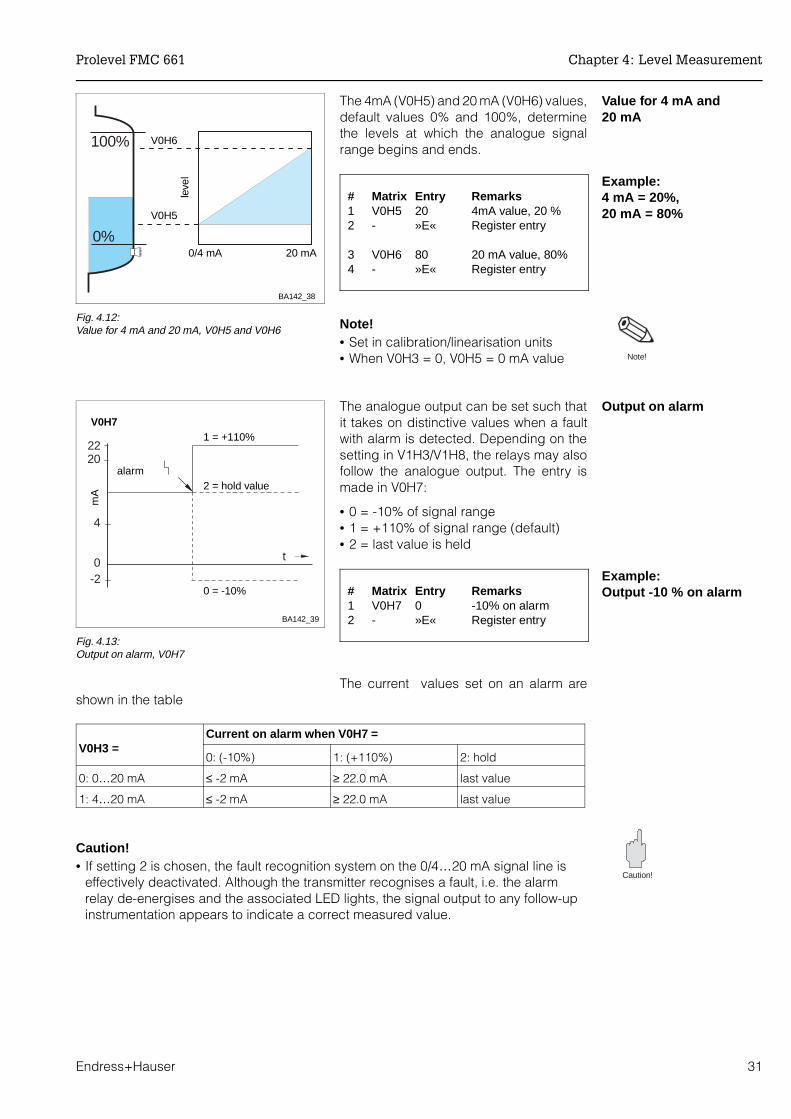
Example: min. fail-safe mode,relays 1a, 1b: switch point 10%,hysteresis 40% relay de-energises onalarm
# Matrix Entry Remarks1 V1H0 e.g. 10 Switch point2 - »E« Register entry
3 V1H1 0 Min. fail-safe mode4 - »E« Register entry
5 V1H2 e.g. 40 Hysteresis —relay energises at 50
6 - »E« Register entry
7 V1H3 0 De-energise on alarm8 - »E« Register entry
9 V1H4 1 Assign to channel 110 - »E« Register entry
Example: max. fail-safe mode,relay 2a, 2bswitch point 90%hysteresis 40%relay follows analogueoutputassigned to channel 1
# Matrix Entry Remarks1 V1H5 e.g. 90 Switch point2 - »E« Register entry
3 V1H6 1 Max. fail-safe mode4 - »E« Register entry
5 V1H7 e.g. 40 Hysteresis ——relay energises at 50
6 - »E« Register entry
7 V1H8 1 Follow outputs8 - »E« Register entry
9 V1H9 1 Assign to channel 210 - »E« Register entry
Note!• The switch point and hysteresis are always entered in the units of calibration or
linearisation• A small hysteresis prevents faulty switching due to turbulence• A large hysteresis allows two-point control of a pump with one relay• For two pairs of relays on channel 1, the hystereses can set such that one pair of
relays de-energises just as the other energises.
11 12 1321 22 23
r u a
11 12 1321 22 23
r u a
rising
falling
de-energiseshyst
eres
is.
e.g
. 40%
V
1H2
relayenergises
switchpoint V1H0
BA
142_
41
e.g. 50%
e.g. 10%
Fig. 4.15:Limit value relay: example for minimum fail-safemode
31 32 3341 42 43
r u a
31 32 3341 42 43
r u arising
falling
relayde-energises
hyst
eres
is.
e.g
. 40%
V
1H7
energises
switchpoint V1H5
BA
142_
42
e.g. 50%
e.g. 90%
Fig. 4.16:Limit value relay: example for maximum fail-safemode
Note!
Prolevel FMC 661 Chapter 4: Level Measurement
Endress+Hauser 33

4.5 Measured value display
The measured value can be read at V0H0. In addition to this, several other fields containsystem information which might be needed, e.g., for trouble-shooting etc.. Table 4.3summarises the displays.
4.6 Parameter locking
When all parameter entries have been made, the matrix can be locked by entering anycode number less that 670 or greater than 679 in V8H9.
Step Matrix Entry Remarks1 V8H9 e.g. 888 Enter any code from 000 - 669 or from 680 - 9992 - »E« Register entry
After locking, all entries can be displayed but not changed.
• The lock is released when a number between 670 and 679 is entered at V8H9.
Note your parameters! The instrument is now configured. Note your parameters in the table at the back of themanual - if you have to replace the transmitter, these can be simply entered in thereplacement Prolevel FMC 661. For level probes on channel 1 there is no need torecalibrate.
Channel 1 Measured value Remarks
V0H0 Level or volume Display in %, m, ft, hl, m3, ft3, t etc. according tocalibration and/or linearisation.The entries for the 0/4 mA and 20 mA value at V0H5and V0H6 control the 10-step LCD bar diagram.
V0H8 Current measuringfrequency channel 1
Displays the frequency which is actually measuredby the probe. Can be used as a fault check (mustchange as level changes)
V0H9 Measured value beforelinearisation
Indicates level before linearisation in the units usedfor calibration
V8H7 Factor for calibrationcorrection
For operating mode 5, displays correction factorused in calibration.Can also be used to enter a density factor whenused with a Deltapilot S
V8H8 Current measuringfrequency channel 2
Displays measuring frequency for Channel 2 whenoperating modes 0, 2 and 5 are selected.
V9H0 Current error code Error code of fault with highest priority appears onfault condition, alarm LED lights or blinks
V9H1 Last error code The previous error can be read and deleted here -press »E« to delete
V9H3 Software version withinstrument code
The first two figures indicate the instrument, the last,the software version; 33 = Version 3.3
V9H4 Rackbus address Indicates RS-485 address set at DIP-switches
Table 4.3:Matrix positions of measured
value displays
Chapter 4: Level Measurement Prolevel FMC 661
34 Endress+Hauser

5 Level Measurement with Limit Switch
This chapter describes the configuration of the Prolevel FMC 661 operating with anexternal limit switch for:
• Level measurement with automatic calibration correction
The external limit switch can also be used for:
• Level measurement on channel 1 with level switching on channel 2• Level limit switching on channel 2 only
The setting of the analogue output, relays, measured value display and parameter uploadand locking are described in Chapter 4.
V0H0
BA142_43
Correctedlevelmeasurement
Measuredvalues
Levelmeasurement+ limit switch
Analogue output
Relays
Correction bydensity factor
Parameter lock
5.1 5.2
4.3 4.4 4.5
4.6
External limitswitch only
Fig. 5.1:Summary: Corrected levelmeasurement and otherapplications with an external limitswitch
Prolevel FMC 661 Chapter 5: Level Measurement with Limit Switch
Endress+Hauser 35

5.1 Level measurement with automatic calibration correction
This level measurement mode employs a Liquiphant or capacitance probe on channel2 to check the validity of the calibration on channel 1. If a descrepancy is found, e.g.because of a change in dielectric constant for capacitance probes or in density forhydrostatic sensors, the level display is corrected.
The level calibration is corrected every time the product passes the external limit switch,i.e. uncovered ⇒ covered or covered ⇒ uncovered.
• If the measured level is less than the installation height of the external limitswitch when this is covered, the value at V8H3 or its volume equivalent isdisplayed at V0H0 until the next automatic calibration,
• If the measured level is greater than the installation height of the external limitswitch when this is uncovered, the value at V8H3 or its volume equivalent isdisplayed at V0H0 until the next automatic calibration.
Installation hints Install the external limit switch where:
• it is frequently covered and uncovered (increases frequency of correction)• as near as possible to 100% (ensures greatest accuracy)
- we recommend a height between 70…90%.
Note!• For Deltapilot S, always use a Liquiphant switch. The use of a capacitance limit
switch causes faulty operation.• Product properties may not change during a filling operation, since there is no
means of continuous compensation.• The external limit switch must operate with all densities (or dielectric constants)
encountered.• If overspill must be avoided at all costs, a separate system must be installed.• The automatic correction mode is not recommended for use with bulk solids.
Note!
Endress+Hauser
PROLEVELFMC671 123.4
1A1B
2A2B3
HV
+
E_
Endress+Hauser
PROLEVELFMC671 123.4
1A1B
2A2B3
HV
+
E_
Liquiphantchannel 2
capacitance probe
channel 1
channel 1
hydrostatic sensor
BA142_44
Liquiphantchannel 2σ, ε ρ
∆h
0%0%
∆h
Fig. 5.2:Level measurement with
automatic calibration correction:for dielectric constant with
capacitance probesfor density with hydrostatic
sensorsA capacitance probe can be
used instead of the Liquiphant(applies to Multicap only)
Chapter 5: Level Measurement with Limit Switch Prolevel FMC 661
36 Endress+Hauser
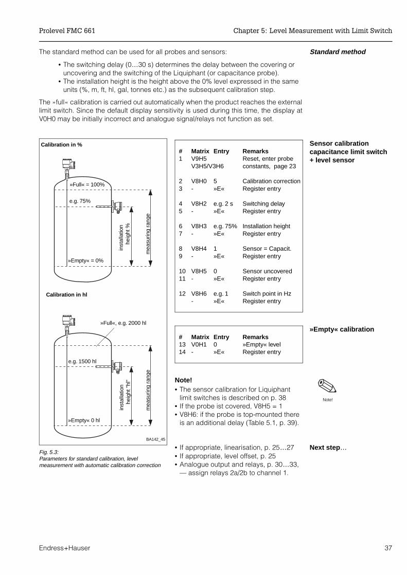
Standard methodThe standard method can be used for all probes and sensors:
• The switching delay (0…30 s) determines the delay between the covering oruncovering and the switching of the Liquiphant (or capacitance probe).
• The installation height is the height above the 0% level expressed in the sameunits (%, m, ft, hl, gal, tonnes etc.) as the subsequent calibration step.
The »full« calibration is carried out automatically when the product reaches the externallimit switch. Since the default display sensitivity is used during this time, the display atV0H0 may be initially incorrect and analogue signal/relays not function as set.
Sensor calibrationcapacitance limit switch+ level sensor
# Matrix Entry Remarks1 V9H5 Reset, enter probe
V3H5/V3H6 constants, page 23
2 V8H0 5 Calibration correction3 - »E« Register entry
4 V8H2 e.g. 2 s Switching delay5 - »E« Register entry
6 V8H3 e.g. 75% Installation height7 - »E« Register entry
8 V8H4 1 Sensor = Capacit.9 - »E« Register entry
10 V8H5 0 Sensor uncovered11 - »E« Register entry
12 V8H6 e.g. 1 Switch point in Hz- »E« Register entry
»Empty« calibration# Matrix Entry Remarks13 V0H1 0 »Empty« level14 - »E« Register entry
Note!• The sensor calibration for Liquiphant
limit switches is described on p. 38• If the probe ist covered, V8H5 = 1 • V8H6: if the probe is top-mounted there
is an additional delay (Table 5.1, p. 39).
Next step … • If appropriate, linearisation, p. 25…27• If appropriate, level offset, p. 25• Analogue output and relays, p. 30…33,
— assign relays 2a/2b to channel 1.
Note!
BA142_45
»Full« = 100%
inst
alla
tion
h
eigh
t %
mea
surin
g ra
nge
e.g. 75%
»Empty« = 0%
»Full«, e.g. 2000 hl
inst
alla
tion
h
eigh
t "hl
"
mea
surin
g ra
nge
e.g. 1500 hl
»Empty« 0 hl
Calibration in %
Calibration in hl
Fig. 5.3:Parameters for standard calibration, levelmeasurement with automatic calibration correction
Prolevel FMC 661 Chapter 5: Level Measurement with Limit Switch
Endress+Hauser 37

Calibration with partiallyfilled vessel
If the following calibration is initially carried out with a hydrostatic pressure sensor usingwater (ρ = 1.0), density can be measured and read off from V8H7.
• If the product changes, the system can be quickly adapted to the newproduct by entering a its density at V8H7. This ensures that the correct level ismeasured as the vessel is filled.
Sensor calibrationLiquiphant limit switch +level probe
# Matrix Entry Remarks1 V9H5 Reset, enter probe
V3H5/V3H6 constants, page 23
2 V8H0 5 Calibration correction3 - »E« Register entry
4 V8H2 e.g. 2 s Switching delay5 - »E« Register entry
6 V8H3 e.g. 75% Installation height7 - »E« Register entry
8 V8H4 0 Sensor = Liquiphant9 - »E« Register entry
Level calibration# Matrix Entry Remarks10 V8H7 1 At »empty« level,
set corr. factor to 111 - »E« Register entry
12 V0H1 e.g. 10% »Empty« level13 - »E« Register entry
14 V8H7 1 At »full« levelset corr. factor to 1
15 - »E« Register entry
16 V0H2 e.g. 90% »Full« level17 - »E« Register entry
Note!• The best accuracy is attained when the
difference between »full« and »empty«levels is as great as possible.
• If the operating mode is temporarilyquit, the Prolevel measures by usingthe sensitivity V3H2 x V8H3. Theindication remains correct as long asthe same product is in the tank.
Next step … • If appropriate, linearisation, p. 25…27• Analogue output and relays, p. 30…33
— assign relays 2a/2b to channel 1.
100%
inst
alla
tion
h
eigh
t
mea
surin
g ra
nge
e.g. 75%
»Empty« e.g. 10%
0%
Note!
V0H1, V8H7
V0H2, V8H7
BA142_46
»Full« e.g. 90%
0%
mea
surin
g ra
nge
Fig. 5.4:Parameters for calibration with partially filled vessel
Chapter 5: Level Measurement with Limit Switch Prolevel FMC 661
38 Endress+Hauser

5.2 External limit switch
Level measurement withlevel switching
Operating mode 0 (V8H0 = 0) of the Prolevel FMC 661 allows level measurement onchannel 1 and separate level switching on channel 2:
# Matrix Remarks1 V9H5/V3H5/V3H6 Reset, enter sensor constants
2 V8H0 Select and register operating mode 0 (=0)
3 V0H1…V0H7 Level calibration, analogue output, Chapter 4.
4 V8H2…V8H6 Calibrate limit switch, capacitance p. 37, Liquiphant p 38.
5 V1H0…V1H4, V1H6 Set relays, for limit switch set fail-safe mode only
Level limit switchingOperating mode 2 (V8H0 = 2) provides level limit switching on channel 2 only. The limitswitch calibration is as described under "Sensor calibration", capacitance probes p. 37,Liquiphant, p 38. For a top-mounted capacitance switch there is an additional delay, seeTable 5.1:
• Set the relay fail-safe mode only• If V1H4 = 2 (channel 2), copy the values in V1H5/V1H7 to V1H0/V1H2.
Endress+Hauser
PROLEVELFMC661 123.4
1A1B
2A2B3
HV
+
E_
capacitance probechannel 1
hydrostatic sensor
BA142_47
Liquiphantchannel 2 max. fail-safe mode
Fig. 5.5:Level measurement and limitswitching on separate channels
Product Dielectricconstant εr
Conductivity Switch point
with ground tube without groundtube
Solvents, oil, fuel <3 low ca. 150 mm ca. 500 mm
dry bulk solids <3 low ca. 350 mm(cable probe)
moist bulk solids >3 medium ca. 150 mm(cable probe)
Table 5.1:Switch point deviation as afunction of product for topmounted capacitance probes anddefault value of 1 Hz = 5 pF
Prolevel FMC 661 Chapter 5: Level Measurement with Limit Switch
Endress+Hauser 39

6 Trouble-Shooting
The Prolevel FMC 661 provides a number of aids for setting up and operating the modulecorrectly. This Chapter contains the following:
• Fault recognition system• Error message and trouble-shooting tables• Simulated operating mode• Commissioning replacement transmitters and sensors• Repairs.
6.1 Fault recognition
Alarms If the Prolevel FMC 661 transmitter recognizes a fault condition where furthermeasurement is impossible, i.e. an alarm:
• the red alarm LED lights (LED 3) and the alarm relay trips• the limit value relays assume respond according to the setting in V1H3/V1H8.• the code for a diagnostic message is to be found in V9H0.
If several faults occur together, the code for the one with the highest priority is displayed.The others can be called up by pressing the »+« or »-« key when field V9H0 is selected.
If the cause of the fault is rectified, its code is no longer displayed:
• the code for the last fault rectified is retained in V9H1• this message can be cleared by pressing the »E« key.
If the power fails, all relays de-energise.
Warnings If the Prolevel FMC 661 transmitter has detected a fault condition where furthermeasurement is possible, i.e. a warning:
• the red alarm LED flashes but the transmitter functions as normal, however,depending on the fault the measured value may be incorrect
• the alarm relay remains energised• the appropriate code is to be found in V9H0.
The codes and error messages are listed in Table 6.1 in the order of their priority.
0% !!
BA142_48
6.1Fault recognition
6.2Incorrectmeasurement
Table 6.1Error messages
Table 6.2Trouble-shooting
6.3Simulation
External limit switchLevelVolume
6.4Maintenance andrepair
Fig. 6.1:Trouble-shooting and fault
elimination for the Prolevel FMC 661
Chapter 6: Trouble-Shooting Prolevel FMC 661
40 Endress+Hauser

Code Type Cause and Remedy
E 101-106 Alarm Fault in instrument electronics- Call Endress+Hauser Service
E 107 Alarm Battery voltage too low- Make back-up of entered parameters immediately- Have battery changed at once by trained personel or ring for service
E 201-202 Alarm Fault in probe on channel 1 (f < 35 Hz; f > 3000 Hz)- Check probe and electronic insert
E 301-302 Alarm Fault in probe on channel 2 (f < 35 Hz; f > 3000 Hz)- Check probe and electronic insert
E 400 Alarm Fault in probe on channels 1 + 2- Check probe, electronic insert and wiring
E 401 Alarm Fault in probe or wiring, channel 1- Check probe, electronic insert and wiring- Incorrect operating mode
E 402 Alarm Fault in probe or wiring, channel 2- Check probe, electronic insert and wiring- Incorrect operating mode
E 600 Warning PFM transmission internal code check- can be ignored if it appears only briefly
E 601 Warning PFM transmission internal code check- can be ignored if it appears only briefly
E 602 Warning Linearisation does not rise monotonously (volume does not increasewith level)- Check and re-enter correct values, reactivate linearization
E 604 Warning Linearisation has less than two sets of values- Enter more values, reactivate linearization
E 606 Warning No stored factory linearization (V2H6 = 0)- Select another linearisation function at V2H0
E 608 Warning Value in V0H5 greater than that in V0H6- Check input
E 610 Warning Calibration fault, channel 1 (»empty« level > »full« level)- Repeat calibration
E 613 Warning Instrument in simulation mode, channel 1- Switch back when finished
E 614 Warning Instrument in simulation mode, channel 2- Switch back when finished
Table 6.1:Error messages Prolevel FMC 661
Prolevel FMC 661 Chapter 6: Trouble-Shooting
Endress+Hauser 41

6.2 Incorrect measurements
Trouble-shooting table Table 6.2 summarises the most common operating errors which lead to incorrectmeasurement by the Prolevel transmitter.
Sensor/channel
Fault Cause and remedy
CapacitanceChannel 1
Measured value wrong • Incorrect calibration? Check measuredvalue before linearisation, V0H9
- if not correct, check whether full and emptycalibration correct V0H1/V0H2
- If correct, check linearization parameters- Check operating mode, V8H0• Change in product- recalibrate for new product• Probe damaged, bent or pressed to side of
vessel- check and remedy• Condensation in connection compartment
Deltapilot SChannel 1
Measured value wrong • Incorrect calibration? Check measured value before linearisation, V0H9
- if not correct, check whether full and emptycalibration correct V0H1/V0H2
- If correct, check linearization parameters- Check operating mode, V8H0• Change in density of product- recalibrate - for Mode 0, 1, 5, enter new density at V8H7• Sensor damaged- check and remedy
Capacitanceor Deltapilot SChannel 1
Relays do not trip correctly • Incorrect settings, e.g. configured in wrongunits
- Check correct units used for all relay settings- Check relay assignments, V1H4, V1H9- Simulate settings in simulation mode - see
Section 6.3, if the relays LEDs switch, checkwiring
CapacitanceChannel 2
Does not switch correctly • Incorrect calibration?- V1H7 ≥ V8H6?- change in product, build-up on probe• Build-up on probe- wire electronic insert for build-up, see
Section 2.4• Settings wrong- type of probe, fail-safe function, switching
delay• Probe damaged, bent or pressed to side of
wall
LiquiphantSoliphantChannel 2
Does not switch correctly • Build-up on probe- clean regularly• Settings wrong- type of probe, fail-safe function, switching
delay• Probe damaged or bent
Table 6.2:Trouble shooting table for
incorrect function without errormessage
Chapter 6: Trouble-Shooting Prolevel FMC 661
42 Endress+Hauser

6.3 Simulated operating mode
This function is intended primarily for checking the correct function of the system:
• Enter 6 at V8H0 to activate the simulation mode for level measurement• Enter 7 at V8H0 to activate the simulation mode for level switching• Enter 0 at V8H0 to terminate simulation and resume normal measurements.
When the simulation mode is activated, the alarm relay flashes (Warning E613 or E614).The following simulations are possible:
Matrix Entry Simulated variable
V9H6 (V8H0 = 7) 0 = switch uncovered100 = switch covered
External limit switchfor Liquiphant values reversed
V9H7 (V8H0 = 6) Level Level, current, volume
V9H8 (V8H0 = 6) Volume Volume, current
V9H9 (V8H0 = 6) Current Current
The level simulation mode takes the last measured value as default value in V9H7.
Example:Simulation of volumeand current by entry oflevel in V9H7
# Matrix Entry Significance1 V8H0 6 Select simulation2 - »E« Register entry
3 V9H7 e.g. 80% Enter level4 - »E« Register entry
5 V9H8 **.** Volume for level
6 V9H9 **.** Current for level
7 V8H0 e.g. 1 Measurement mode8 - »E« Register entry
Example:Simulation of current byentry of volume in V9H8
# Matrix Entry Significance1 V8H0 6 Select simulation2 - »E« Register entry
3 V9H8 e.g. 500 Volume = 500 hl
4 V9H9 **.** Current for volume
5 V8H0 e.g. 1 Measurement mode6 - »E« Register entry
Example:Simulation of coveredexternal limit switch
# Matrix Entry Significance1 V8H0 7 Select simulation2 - »E« Register entry
3 V9H6 100 Switch covered
4 V8H0 e.g. 0 Measurement mode5 - »E« Register entry
V9H7
volu
me,
cur
rent
mA
level units
V9H8
curr
ent m
A
volume unitsBA142_49
Fig. 6.2:Simulation mode
Prolevel FMC 661 Chapter 6: Trouble-Shooting
Endress+Hauser 43

6.4 Exchanging transmitters and sensors
FMC 661 transmitter If the Prolevel FMC 661 has to be exchanged, the replacement need not be recalibrated.Simply enter the settings which you have noted in the Table at the back of the manual.For versions with Rackbus RS-485 interface, the parameters can be downloaded fromthe computer.
• Sequences requiring a particular order must be re-entered in that order• Any linearisation must be manually reactivated by entering the mode in V2H0.
Capacitance probeswith EC 37 Z/EC 47 Z
For level measurement, provided the sensor constants were entered before calibration,it is not necessary to recalibrate the instrument when the electronic insert is replaced.On replacement:
• the zero frequency (or offset) fo and • sensitivity S
for the range selected (default Range II) must be entered at V3H5 and V3H6 respectively.Fig. 2.2 shows where the information is to be found on the EC 37 Z and EC 47 Z inserts.
• If a different range is selected, the transmitter must be recalibrated.• If the constants were not entered a recalibration is necessary.
ProcedureStep Matrix Entry Significance1 V3H5 e.g. 57.2 Enter zero frequency (offset)2 - »E« Register entry
3 V3H6 e.g. 0.652 Enter sensitivity4 - »E« Register entry
EC 17 Z insert If the capacitance probe was used for limit switching on channel 2, a recalibration isnecessary.
Deltapilot S Provided a »dry« calibration was made or the sensor constants were entered beforecalibration, it is not necessary to recalibrate the instrument when the electronic insert isreplaced. The measurement can be taken up again as soon as the new constants havebeen entered in the matrix.
• If the old sensor constants were not entered, the system must be recalibrated.
The new sensor constants are found in table 2.2., p. 13.
• fo is the zero frequency (or offset)— the zero frequency may also be read from V0H8 when the probe isunpressurised. This value gives slightly better accuracy, since it accounts forthe orientation of the probe.
• ∆f is the sensitivity
Liquiphant No recalibration is necessary if the Liquiphant is exchanged.
Chapter 6: Trouble-Shooting Prolevel FMC 661
44 Endress+Hauser

6.5 Repairs
Should the Prolevel FMC 661 transmitter or its sensor need to be repaired byEndress+Hauser, please send it to your nearest Service Centre with a note containingthe following information:
• An exact description of the application for which it was used.• The physical and chemical properties of the product measured.• A short description of the fault.
Caution!• Special precautions must be observed when sending probes for repair:
• Remove all visible traces of product from the probe.• If the product can impair health, i.e. is corrosive, poisonous, carcinogenic,
radioactive etc., please check that the probe is thoroughly decontaminated.• If the last traces of dangerous products cannot be removed, e.g. product has
penetrated into fissures or diffused into plastic parts, we kindly ask you not tosend the probe for repair.
Caution!
Prolevel FMC 661 Chapter 6: Trouble-Shooting
Endress+Hauser 45

7 Appendix
7.1 Calibration and linearisation in volume units
Use the following two procedures if you can calibrate in volume units only but still requirea linearisation.
Linearisation, horizontalcylinder
The parameters must be entered in theorder below. Two parameters are entered:
• Tank diameter, D• Tank volume, V.
# Matrix Entry Remarks1 V9H5 670 Reset2 - »E« Register entry
3 V3H5 fo Zero frequency4 - »E« Register entry
5 V3H6 ∆f Sensitivity6 - »E« Register entry
7 V3H0 1 Volume units8 - »E« Register entry
9 V2H7 D Tank diameter, %, m or ft
10 - »E« Register entry
11 V2H8 V Tank volume*,hl, gal…
12 - »E« Register entry
13 V2H0 1 Activate linearisation14 - »E« Register entry
15 V0H1 E Tank empty, currentvolume in hl, gal…
16 - »E« Register entry
17 V0H2 F Tank full, currentvolume in hl, gal…
18 - »E« Register entry
Note!• D determines the level units at V0H9• If V =100 is entered, the calibration
must be made in % volume units
After linearisation • Volume is displayed at V0H0• Level is displayed at V0H9
Next step … Set analogue output and relays in volumeunits, see p. 30…33.
V0H1
V0H2
D (V2H7)
V (V2H8)
»Empty« vol. E(0…40%)
»Full« vol. F(60…100%)
BA142_50
probe or sensor covered
zero point for calibration
zero point for calibration
100% = V (V2H8)
Fig. 7.1:Parameters for calibration and linearisation in ahorizontal cylinder
Note!
Chapter 7: Appendix Prolevel FMC 661
46 Endress+Hauser

Linearisation for tankswith conical outlet
You require a linearisation table, H/V orH/G, max. 30 pairs in increasing order
• Level H in %, m or ft• Volume V or weight G in customer units.
# Matrix Entry Remarks1 V9H5 670 Reset2 - »E« Register entry
3 V3H5 fo Zero frequency4 - »E« Register entry
5 V3H6 ∆f Sensitivity6 - »E« Register entry
7 V3H0 1 Volume units8 - »E« Register entry
9 V2H1 0 Manual10 - »E« Register entry
11 V2H2 1 Table no.12 - »E« Register entry
13 V2H3 V/G1…30 Volume/weight*14 - »E« Register entry
15 V2H4 H1…30 Level m or ft*16 - »E« Register entry
17 V2H5 »E« Next table no.*— springs to V2H3
*Repeat #13…17 until all values entered
18 V2H0 3 Activate "manual"19 - »E« Register entry
20 V0H1 E Tank empty, currentvolume in hl, gal…
21 - »E« Register entry
22 V0H2 F Tank full, currentvolume in hl, gal…
23 - »E« Register entry
Note!• First pair ~ 0 % level, in %, m, ft.
last pair ~ 100 % level, in %, m, ft. • On error E602 or E604, correct table.
Re-activate linearisation in V2H0.
After linearisation• Volume/weight is displayed at V0H0• Level is displayed at V0H9
Next step …Set analogue output and relays in volumeor weight units, p. 30…33.
Note!
123
45
67
8
H
V/G
V0H1
V0H2
V2H0...V2H5
BA142_51
»Empty« volume E(0…40%)
»Full« volume F(60…100%)
probe or sensorcovered
V2H4
H1
H2…H30
V2H3
V/G1
V/G2…V/G30
zero point of calibration =zero point of linearisation
zero point of calibration
Fig. 7.2:Parameters for calibration and linearisation in a tankwith conical outlet
Prolevel FMC 661 Chapter 7: Appendix
Endress+Hauser 47
Index
AAlarm 31 - 32, 40All-weather cover 14Ambient temperature 14Analogue output 13, 30, 31
4 mA and 20 mA values 31output damping 30output on alarm 31signal range 30
Application 6
BBus address and termination 18
CCalibration
»dry« for hydrostatic sensors 28horizontal cylinders 25level 24level measurement with calibration correction 37 - 38upright cylinders 24
Certificates 3Commulog VU 260 Z 18, 19, 21Controls 19 - 22
DDeltapilot sensors 44Density correction 28 - 29, 38
EElectronic inserts 16Environment 11Error messages 41External limit switch 39
GGeneral specifications 10
IInput characteristics 10Installation 12 - 18
KKeyboard and display 20
LLevel limit switching 39Level measurement 23 - 34Level measurement with level switching 39Linearisation 46 - 47
Deletion of value pairs 27horizontal cylindrical tanks 25, 46semi-automatic with controlled filling 27tanks with conical outlet 47
Location 14
MMax. fail-safe mode 33Measured value display 34Measuring system 7Mechanical specifications 11Min. fail-safe mode 33Mounting 14
OOperating matrix 19Operating mode 9, 36, 39Operating parameters back coverOutput characteristics 10 - 11
PParameter lock 34Post mounting 14Power supply 18Probes and sensors 13
RRackbus RS-485 15, 18, 22Relays 9, 15, 32, 40
alarm relay 40assignment 32fail-safe mode 32hysteresis 32min. and max. fail-safe mode 33operating modes 32relay on alarm 32switch point 32
Remote operation 18Repairs 45
SSafety 3Sensor cable 16Sensor constants 12, 23, 44Sensors, exchange of 44Simulated operation 43
TTechnical data 10Terminal resistance 18Trouble-shooting 40 - 45
WWarning 4, 40Wiring
Rackbus RS-485 18Sensors 16Transmitter 15
Prolevel FMC 661 Index
48 Endress+Hauser

Operating Matrix
Operating and default parameters
Enter your operating parameters in the matrix below.
H0 H1 H2 H3 H4 H5 H6 H7 H8 H9
V0
V1
V2
V3
V4
V5
V6
V7
V8
V9
Display field
The default parameters are as indicated below.
H0 H1 H2 H3 H4 H5 H6 H7 H8 H9
V0 0.0 100.0 0 1 0.0 100.0 1
V1 90.0 1 2.0 0 1 90.0 1 0.1 0 2
V2 0 0 1 0.0 0.0 1 100 100
V3 0 0.0 10.0 0.0 0.0 1.0
V4
V5
V6
V7
V8 1 1 90.0 1 0 1.0 1.0 670
V9 E E 532 0 0.0 0.0 0.0 0.0
Display field
Prolevel FMC 661 Operating matrix
Endress+Hauser

H0 H1 H2 H3 H4 H5 H6 H7 H8 H9
V0CalibrationChannel 1
Measuredvalue
Emptycalibration
Fullcalibration
Selectcurrent
0=0…20mA
1=4…20mA
Outputdamping
(s)
Value for0/4 mA
Value for20 mA
Safetyalarm
0 = -10%
1=+110%
2=Hold
Actualmeasuringfrequencychannel 1
Measuredvaluebefore
linearization
V1Limit valueChannel 1
Relay 1switching
point
Relay 1fail-safe mode
0 = min.
1 = max.
Relay 1hysteresis
Relay 1at alarm
0 = de-energise
1 = as V0H7
SelectRelay 1
1 = channel 1
2 = channel 2
Relay 2switching
point
Relay 2fail-safe mode
0 = min.
1 = max.
Relay 2hysteresis
Relay 2at alarm
0 = de-energise
1 = as V0H7
SelectRelay 2
1 = channel 1
2 = channel 2
V2LinearisationChannel 1
Linearisation0=linear
1= hor. cylinder3=manual4=clear 3
Level inputmode
0=manual1=auto.
Table No.
(1…30)
InputVolume/Weight
InputLevel
NextTable No.
Diameterfor
horizontalcylinder
Volumefor
horizontalcylinder
V3ExtendedCalibrationChannel 1
Calibrationmode0=level
1= volume
Offset Sensitivity Zero offsetvalue
Offsetof device
(zerofrequency)
Sensitivityof device
For Serviceonly
(0 mA D/Acalibration)
For Serviceonly
20 mA D/Acalibration)
V4
V5
V6 .
V7
V8Operatingmode
0 = level/switch1= level
2 = switch5 = corr. level6 = sim. FMC7 = sim. FTC
Switchdelay time
(s)
Sensorposition forcorr. cal.
Type ofsensor
0=DL 17 Z 1=EC 17 Z
CalibrationEC 17 Z0=free
1=covered
CalibrationEC 17 ZSwitch point
0.1…100 Hz
Factor forcalibrationcorrection
Actualfrequencymeasuringchannel 2
Securitylocking
< 670 or> 679
V9ServiceandSimulation
Currentdiagnostic
code
Last diagnostic
codeE=clear
Instrumentand
Softwareversion
Rackbusaddress
Reset todefaultvalues
670…679
Simulationfrequency
Simulationlevel
Simulationvolume
Simulationcurrent
VAVU 260 ZZA 672only
Tag. No.channel 1
Tag No.channel 2
Units channel 1
beforelinearisation
Units channel 1
afterlinearisation
Display channel 1
beforelinearisation
Displaychannel 1
afterlinearisation
Display field
Parameter Matrix
Operating matrix Prolevel FMC 661
Endress+Hauser


Europe
Austria Endress+Hauser Ges.m.b.H.WienTel. (01) 88056-0, Fax (01) 88056-35
BelarusBelorgsintezMinskTel. (01 72) 26 31 66, Fax (0172) 263111
Belgium Endress+Hauser S.A./N.V.BrusselsTel. (02) 2480600, Fax (02) 2480553
BulgariaINTERTECH-AUTOMATIONSofiaTel. (02) 65 28 09, Fax (02) 652809
Croatia Endress+Hauser GmbH+Co.ZagrebTel. (01) 6601418, Fax (01) 6601418
CyprusI+G Electrical Services Co. Ltd.NicosiaTel. (02) 48 47 88, Fax (02) 484690
Czech Republic Endress+Hauser GmbH+Co.PrahaTel. (026) 6 78 42 00, Fax (0 26) 6784179
Denmark Endress+Hauser A/SSøborgTel. (31) 67 31 22, Fax (31) 673045
EstoniaElvi-AquaTartuTel. (7) 422726, Fax (7) 422727
Finland Endress+Hauser OyEspooTel. (90) 8596155, Fax (90) 8596055
France Endress+HauserHuningueTel. 89696768, Fax 89694802
Germany Endress+Hauser Meßtechnik GmbH+Co.Weil am RheinTel. (07621) 9 75-01, Fax (07621) 9 75-5 55
Great Britain Endress+Hauser Ltd.ManchesterTel. (01 61) 2865000, Fax (01 61) 9981841
GreeceI & G Building Services Automation S.A.AthensTel. (01) 9241500, Fax (01) 9221714
HungaryMile Ipari-ElektroBudapestTel. (01) 2615535, Fax (01) 2615535
IcelandVatnshreinsun HFReykjavikTel. (05) 88 96 16, Fax (05) 889613
IrelandFlomeaco Company Ltd.KildareTel. (045) 868615, Fax (045) 868182
Italy Endress+Hauser Italia S.p.A.Cernusco s/N MilanoTel. (02) 92 10 64 21, Fax (02) 92107153
JugoslaviaMeris d.o.o.BeogradTel. (11) 4442966, Fax (11) 43 00 43
LatviaRaita Ltd.RigaTel. (02) 25 47 95, Fax (02) 7 25 89 33
LithuaniaAgava Ltd.KaunasTel. (07) 20 24 10, Fax (07) 207414
Luxembourg Endress+Hauser S.A./N.V.BrusselsTel. (02) 2 48 06 00, Fax (02) 2 48 05 53
Netherland Endress+Hauser B.V.NaardenTel. (0 35) 6958611, Fax (035) 6 95 88 25
Norway Endress+Hauser A/STranbyTel. (0 32) 85 10 85, Fax (0 32) 85 11 12
PolandEndress+Hauser Polska Sp. z o.o.WarszawyTel. (0 22) 7201090, Fax (022) 7 20 10 85
PortugalTecnisis - Tecnica de Sistemas IndustriaisLinda-a-VelhaTel. (01) 4 17 26 37, Fax (01) 4 18 52 78
RomaniaRomconseng SRLBucharestTel. (01) 4 10 16 34, Fax (01) 4 10 16 34
RussiaEndress+Hauser Moscow OfficeMoscowTel., Fax: see Endress+Hauser GmbH+Co.Instruments International
Slovak RepublicTranscom Technik s.r.o.BratislavaTel. (7) 5213161, Fax (7) 5 21 31 81
SloveniaEndress+Hauser D.O.O.LjubljanaTel. (0 61) 1592217, Fax (061) 1 59 22 98
Spain Endress+Hauser S.A.BarcelonaTel. (93) 4 80 33 66, Fax (93) 4 73 38 39
Sweden Endress+Hauser ABSollentunaTel. (08) 6 26 16 00, Fax (08) 6 26 94 77
Switzerland Endress+Hauser AGReinach/BL 1Tel. (0 61) 7156222, Fax (061) 7 11 16 50
TurkeyIntek Endüstriyel Ölcü ve Kontrol SistemleriIstanbulTel. (0212) 2 75 13 55, Fax (0212) 2 66 27 75
UkraineIndustria UkraïnaKievTel. (44) 2 68 52 13, Fax (44) 2 68 52 13
Africa
EgyptAnasiaHeliopolis/CairoTel. (02) 4 17 90 07, Fax (02) 4 17 90 08
MoroccoOussama S.A.CasablancaTel. (02) 241338, Fax (02) 40 26 57
NigeriaJ F Technical Invest. Nig. Ltd.LagosTel. (1) 62 23 45 46, Fax (1) 62 23 45 48
South Africa Endress+Hauser Pty. Ltd.SandtonTel. (0 11) 4441386, Fax (011) 4 44 19 77
TunisiaControle, Maintenance et RegulationTunisTel. (01) 793077, Fax (01) 78 85 95
America
Argentina Endress+Hauser Argentina S.A.Buenos AiresTel. (01) 5 23 80 08, Fax (01) 5 22 05 46
BoliviaTritec S.R.L.CochabambaTel. (042) 5 69 93, Fax (0 42) 50981
Brazil Samson Endress+Hauser Ltda.Sao PauloTel. (011) 5 36 34 55, Fax (0 11) 5363067
Canada Endress+Hauser Ltd.Burlington, OntarioTel. (905) 6 81 92 92, Fax (9 05) 6819444
ChileDIN Instrumentos Ltda.SantiagoTel. (02) 2050100, Fax (02) 2258139
ColombiaColsein Ltd.Bogota D.C.Tel. (01) 2367659, Fax (01) 6107868
Costa RicaEURO-TEC S.A.San JoseTel. 2 96 15 42, Fax 2961542
EcuadorInsetec Cia. Ltda.QuitoTel. (02) 25 12 42, Fax (02) 461833
GuatemalaACISA Automatizacion Y Control Industrial S.A.Ciudad de Guatemala, C.A.Tel. (02) 34 59 85, Fax (02) 327431
Mexico Endress+Hauser I.I.Mexico CityTel. (5) 5 68 96 58, Fax (5) 5684183
ParaguayIncoel S.R.L.AsuncionTel. (021) 213989, Fax (021) 2 65 83
UruguayCircular S.A.MontevideoTel. (02) 92 57 85, Fax (02) 929151
USA Endress+Hauser Inc.Greenwood, IndianaTel. (317) 5 35-7138, Fax (317) 5 35-1489
VenezuelaH. Z. Instrumentos C.A.CaracasTel. (02) 9798813, Fax (02) 9799608
Asia
China Endress+Hauser Shanghai
Instrumentation Co. Ltd.ShanghaiTel. (021) 64646700, Fax (021) 64747860
Endress+Hauser Beijing OfficeBeijingTel. (010) 68344058, Fax (010) 68344068
Hong Kong Endress+Hauser (H.K.) Ltd.Hong KongTel. 25283120, Fax 28654171
India Endress+Hauser India Branch OfficeMumbaiTel. (022) 6 04 55 78, Fax (0 22) 6040211
IndonesiaPT Grama BazitaJakartaTel. (21) 7975083, Fax (21) 7975089
Japan Sakura Endress Co., Ltd.TokyoTel. (04 22) 54 06 11, Fax (0422) 550275
Malaysia Endress+Hauser (M) Sdn. Bhd.Petaling Jaya, Selangor Darul EhsanTel. (03) 7334848, Fax (03) 7338800
PakistanSpeedy AutomationKarachiTel. (021) 7 72 29 53, Fax (0 21) 7736884
Papua-NeuguineaSBS Electrical Pty LimitedPort MoresbyTel. 53 25 11 88, Fax 53 25 95 56
PhilippinesBrenton Industries Inc.Makati Metro ManilaTel. (2) 8430661-5, Fax (2) 8 17 57 39
Singapore Endress+Hauser (S.E.A.) Pte., Ltd.SingaporeTel. 4688222, Fax 4 66 68 48
South Korea Endress+Hauser (Korea) Co., Ltd.SeoulTel. (02) 6 58 72 00, Fax (02) 6 59 28 38
TaiwanKingjarl CorporationTaipei R.O.C.Tel. (02) 7 18 39 38, Fax (02) 7 13 41 90
Thailand Endress+Hauser Ltd.BangkokTel. (2) 9967811-20, Fax (2) 9967810
VietnamTan Viet Bao Co. Ltd.Ho Chi Minh CityTel. (08) 8 33 52 25, Fax (08) 8 33 52 27
IranTelephone Technical Services Co. Ltd.TehranTel. (0 21) 8746750, Fax(0 21) 8737295
IsraelInstrumetrics Industrial Control Ltd.Tel-AvivTel. (03) 6 48 02 05, Fax (03) 6 47 19 92
JordanA.P. Parpas Engineering S.A.AmmanTel. (06) 5 53 92 83, Fax (06) 5 53 92 05
Kingdom of Saudi ArabiaAnasiaJeddahTel. (02) 6 71 00 14, Fax (02) 6 72 59 29
KuwaitKuwait Maritime & Mercantile Co. K.S.C.SafatTel. 2434752, Fax 2 44 14 86
LebanonNabil IbrahimJbeilTel. (3) 25 40 51, Fax (9) 94 40 80
Sultanate of OmanMustafa & Jawad Sience & Industry Co.L.L.C.RuwiTel. 60 20 09, Fax 60 70 66
United Arab EmiratesDescon Trading EST.DubaiTel. (04) 359522, Fax (04) 35 96 17
YemenYemen Company for Ghee and Soap IndustryTaizTel. (04) 230664, Fax (04) 21 23 38
Australia + New Zealand
AustraliaGEC Alsthom LTD.SydneyTel. (02) 96450777, Fax (02) 97 43 70 35
New ZealandEMC Industrial InstrumentationAucklandTel. (09) 4 44 92 29, Fax (09) 4 44 11 45
All other countries
Endress+Hauser GmbH+Co.Instruments International
D-Weil am RheinGermanyTel. (0 76 21) 975-02, Fax (0 76 21) 97 53 45
12.97/MTM
BA 142F/00/en/07.98a016562-1000CCS/CV4.2
Members of the Endress+Hauser group
Hauser+Endress
http://www.endress.com