proline prosonic flow 93c foundation fieldbus -...
TRANSCRIPT

BA00146D/06/EN/13.10
71121229
Valid as of version:
V 3.00.XX
Description of Device Functions
Proline Prosonic Flow 93C
FOUNDATION Fieldbus
Ultrasonic flow measuring system
9
0000 0001 0002 0003 0004 0005000AAAA
1000 1001 1002 1003 1004 1005100BAAB
2000 2001 2002 2003 2004 2005200CAAC
3000 3001 3002 3003 3004 3005300DAAD
4000 4001 4002 4003 4004 4005400EAAE
5000 5001 5002 5003 5004500FAAF
4200
5200
4201
5201
4202
5202
4203
5203
4204 4205420
520
2400 2401 2402 2403 2404 2405240CCA
2200 2201 2202 2203 2204 2205220CBA
0200 0201 0202 0203 0204 0205020

Device Functions of the Proline Prosonic Flow 93 FOUNDATION Fieldbus
2 Endress+Hauser
Operation of Proline Prosonic Flow 93C FOUNDATION Fieldbus
- with local operation: see Page 3
- with FOUNDATION Fieldbus: see Page 75

Device Functions of the Proline Prosonic Flow 93C FOUNDATION Fieldbus Content for Local operation
Endress+Hauser 3
Content for Local operation
1 Using this Manual . . . . . . . . . . . . . . . . . . . . . . . . . . . . . . . . . . . . . . . . . . . . . . . . . 5
1.1 Using the table of contents to locate a function description . . . . . . . . . . . . . . . . . . . . . . 5
1.2 Using the graphic of the function matrix to locate a function description . . . . . . . . . . . 5
1.3 Using the index of the function matrix to locate a function description . . . . . . . . . . . . . 5
2 Function matrix . . . . . . . . . . . . . . . . . . . . . . . . . . . . . . . . . . . . . . . . . . . . . . . . . . . 6
2.1 General layout of the function matrix . . . . . . . . . . . . . . . . . . . . . . . . . . . . . . . . . . . . . 6
2.1.1 Blocks (A, B, C, etc.) . . . . . . . . . . . . . . . . . . . . . . . . . . . . . . . . . . . . . . . . . . . . 6
2.1.2 Groups (AAA, AEA, CAA, etc.) . . . . . . . . . . . . . . . . . . . . . . . . . . . . . . . . . . . . 6
2.1.3 Function groups (000, 020, 060, etc.) . . . . . . . . . . . . . . . . . . . . . . . . . . . . . . . 6
2.1.4 Functions (0000, 0001, 0002, etc.) . . . . . . . . . . . . . . . . . . . . . . . . . . . . . . . . . 6
2.1.5 Codes identifying cells . . . . . . . . . . . . . . . . . . . . . . . . . . . . . . . . . . . . . . . . . . . 7
2.2 Illustration of the function descriptions . . . . . . . . . . . . . . . . . . . . . . . . . . . . . . . . . . . . 7
2.3 Display lines on the local display . . . . . . . . . . . . . . . . . . . . . . . . . . . . . . . . . . . . . . . . . 8
2.4 Function matrix of the Prosonic Flow 93C FOUNDATION Fieldbus . . . . . . . . . . . . . . . 8
3 Block MEASURED VARIABLES . . . . . . . . . . . . . . . . . . . . . . . . . . . . . . . . . . . 9
3.1 Group MEASURING VALUES . . . . . . . . . . . . . . . . . . . . . . . . . . . . . . . . . . . . . . . . . . 10
3.1.1 Function group MAIN VALUES CH1 . . . . . . . . . . . . . . . . . . . . . . . . . . . . . . . 10
3.1.2 Function group MAIN VALUES CH2 . . . . . . . . . . . . . . . . . . . . . . . . . . . . . . . 10
3.1.3 Function group CALCULATED MAIN VALUES . . . . . . . . . . . . . . . . . . . . . . . .11
3.2 SYSTEM UNITS groups . . . . . . . . . . . . . . . . . . . . . . . . . . . . . . . . . . . . . . . . . . . . . . . 12
3.2.1 Function group CONFIGURATION . . . . . . . . . . . . . . . . . . . . . . . . . . . . . . . . 12
3.2.2 Function group ADDITIONAL CONFIGURATION . . . . . . . . . . . . . . . . . . . . 14
4 Block QUICK-SETUP . . . . . . . . . . . . . . . . . . . . . . . . . . . . . . . . . . . . . . . . . . . . . 16
4.1 Quick Setup . . . . . . . . . . . . . . . . . . . . . . . . . . . . . . . . . . . . . . . . . . . . . . . . . . . . . . . 17
4.1.1 Quick Setup "Commissioning" . . . . . . . . . . . . . . . . . . . . . . . . . . . . . . . . . . . . 17
4.1.2 Data backup/transmission . . . . . . . . . . . . . . . . . . . . . . . . . . . . . . . . . . . . . . . .18
5 Block USER INTERFACE . . . . . . . . . . . . . . . . . . . . . . . . . . . . . . . . . . . . . . . . . 19
5.1 Group CONTROL . . . . . . . . . . . . . . . . . . . . . . . . . . . . . . . . . . . . . . . . . . . . . . . . . . . 20
5.1.1 Function group BASIC CONFIGURATION . . . . . . . . . . . . . . . . . . . . . . . . . . 20
5.1.2 Function group UNLOCKING/LOCKING . . . . . . . . . . . . . . . . . . . . . . . . . . . .22
5.1.3 Function group OPERATION . . . . . . . . . . . . . . . . . . . . . . . . . . . . . . . . . . . . . .23
5.2 Group MAIN LINE . . . . . . . . . . . . . . . . . . . . . . . . . . . . . . . . . . . . . . . . . . . . . . . . . . 24
5.2.1 Function group CONFIGURATION . . . . . . . . . . . . . . . . . . . . . . . . . . . . . . . . 24
5.2.2 Function group MULTIPLEX . . . . . . . . . . . . . . . . . . . . . . . . . . . . . . . . . . . . . .26
5.3 Group ADDITION LINE . . . . . . . . . . . . . . . . . . . . . . . . . . . . . . . . . . . . . . . . . . . . . . 27
5.3.1 Function group CONFIGURATION . . . . . . . . . . . . . . . . . . . . . . . . . . . . . . . . 27
5.3.2 Function group MULTIPLEX . . . . . . . . . . . . . . . . . . . . . . . . . . . . . . . . . . . . . .29
5.4 Group INFORMATION LINE . . . . . . . . . . . . . . . . . . . . . . . . . . . . . . . . . . . . . . . . . . 31
5.4.1 Function group CONFIGURATION . . . . . . . . . . . . . . . . . . . . . . . . . . . . . . . . 31
5.4.2 Function group MULTIPLEX . . . . . . . . . . . . . . . . . . . . . . . . . . . . . . . . . . . . . .33
6 Block TOTALIZERS . . . . . . . . . . . . . . . . . . . . . . . . . . . . . . . . . . . . . . . . . . . . . . 35
6.1 Group TOTALIZER (1 to 3) . . . . . . . . . . . . . . . . . . . . . . . . . . . . . . . . . . . . . . . . . . . . 36
6.1.1 Function group CONFIGURATION . . . . . . . . . . . . . . . . . . . . . . . . . . . . . . . . 36
6.1.2 Function group OPERATION . . . . . . . . . . . . . . . . . . . . . . . . . . . . . . . . . . . . . 38
6.2 Group HANDLING TOTAL. . . . . . . . . . . . . . . . . . . . . . . . . . . . . . . . . . . . . . . . . . . . 39

Content for Local operation Device Functions of the Proline Prosonic Flow 93C FOUNDATION Fieldbus
4 Endress+Hauser
7 Block BASIC FUNCTION . . . . . . . . . . . . . . . . . . . . . . . . . . . . . . . . . . . . . . . . 40
7.1 Group FOUNDATION FIELDBUS . . . . . . . . . . . . . . . . . . . . . . . . . . . . . . . . . . . . . . . 41
7.1.1 Function group CONFIGURATION . . . . . . . . . . . . . . . . . . . . . . . . . . . . . . . . 41
7.1.2 Function group FUNCTION BLOCKS . . . . . . . . . . . . . . . . . . . . . . . . . . . . . . . 42
7.1.3 Function group INFORMATION . . . . . . . . . . . . . . . . . . . . . . . . . . . . . . . . . . . 43
7.2 Group PROCESS PARAMETER (CH1 to CH2) . . . . . . . . . . . . . . . . . . . . . . . . . . . . . . 44
7.2.1 Function group CONFIGURATION . . . . . . . . . . . . . . . . . . . . . . . . . . . . . . . . 44
7.2.2 Function group ADJUSTMENT . . . . . . . . . . . . . . . . . . . . . . . . . . . . . . . . . . . . 46
7.2.3 Function group LIQUID DATA . . . . . . . . . . . . . . . . . . . . . . . . . . . . . . . . . . . . 47
7.3 Group SYSTEM PARAMETER (CH1 to CH2) . . . . . . . . . . . . . . . . . . . . . . . . . . . . . . . 50
7.3.1 Function group CONFIGURATION . . . . . . . . . . . . . . . . . . . . . . . . . . . . . . . . 50
7.4 Group SENSOR DATA (CH1 to CH2) . . . . . . . . . . . . . . . . . . . . . . . . . . . . . . . . . . . . . 52
7.4.1 Function group CONFIGURATION . . . . . . . . . . . . . . . . . . . . . . . . . . . . . . . . 52
7.4.2 Function group MEASURING TUBE . . . . . . . . . . . . . . . . . . . . . . . . . . . . . . . . 53
7.4.3 Function group SENSOR PARAMETER . . . . . . . . . . . . . . . . . . . . . . . . . . . . . . 54
7.4.4 Function group CALIBRATION DATA. . . . . . . . . . . . . . . . . . . . . . . . . . . . . . . 56
7.4.5 Function group ORIG. FACT. CALIBR. . . . . . . . . . . . . . . . . . . . . . . . . . . . . . 57
8 Block SUPERVISION . . . . . . . . . . . . . . . . . . . . . . . . . . . . . . . . . . . . . . . . . . . . . 58
8.1 Group SYSTEM (SYSTEM CH2) . . . . . . . . . . . . . . . . . . . . . . . . . . . . . . . . . . . . . . . . . 59
8.1.1 Function group CONFIGURATION . . . . . . . . . . . . . . . . . . . . . . . . . . . . . . . . 59
8.1.2 Function group OPERATION . . . . . . . . . . . . . . . . . . . . . . . . . . . . . . . . . . . . . 60
8.2 Group VERSION INFO . . . . . . . . . . . . . . . . . . . . . . . . . . . . . . . . . . . . . . . . . . . . . . . . 63
8.2.1 Function group DEVICE . . . . . . . . . . . . . . . . . . . . . . . . . . . . . . . . . . . . . . . . . 63
8.2.2 Function group SENSOR . . . . . . . . . . . . . . . . . . . . . . . . . . . . . . . . . . . . . . . . 63
8.2.3 Function group AMPLIFIER . . . . . . . . . . . . . . . . . . . . . . . . . . . . . . . . . . . . . . 63
8.2.4 Function group F-CHIP . . . . . . . . . . . . . . . . . . . . . . . . . . . . . . . . . . . . . . . . . 64
8.2.5 Function group I/O MODULE . . . . . . . . . . . . . . . . . . . . . . . . . . . . . . . . . . . . 64
9 Factory settings . . . . . . . . . . . . . . . . . . . . . . . . . . . . . . . . . . . . . . . . . . . . . . . . . . 65
9.1 SI units . . . . . . . . . . . . . . . . . . . . . . . . . . . . . . . . . . . . . . . . . . . . . . . . . . . . . . . . . . . 65
9.1.1 Low flow cutoff, totalizer . . . . . . . . . . . . . . . . . . . . . . . . . . . . . . . . . . . . . . . . 65
9.1.2 Language . . . . . . . . . . . . . . . . . . . . . . . . . . . . . . . . . . . . . . . . . . . . . . . . . . . . 65
9.1.3 Length, temperature . . . . . . . . . . . . . . . . . . . . . . . . . . . . . . . . . . . . . . . . . . . . 65
9.2 US units (for USA and Canada only) . . . . . . . . . . . . . . . . . . . . . . . . . . . . . . . . . . . . . . 66
9.2.1 Low flow cutoff, totalizer . . . . . . . . . . . . . . . . . . . . . . . . . . . . . . . . . . . . . . . . 66
9.2.2 Language, length, temperature . . . . . . . . . . . . . . . . . . . . . . . . . . . . . . . . . . . . 66
10 Index Function matrix . . . . . . . . . . . . . . . . . . . . . . . . . . . . . . . . . . . . . . . . . . . 67
11 Index . . . . . . . . . . . . . . . . . . . . . . . . . . . . . . . . . . . . . . . . . . . . . . . . . . . . . . . . . . . . . 70

Device Functions of the Proline Prosonic Flow 93C FOUNDATION Fieldbus 1 Using this Manual
Endress+Hauser 5
1 Using this Manual
There are various ways of locating the description of a function of your choice in the manual:
1.1 Using the table of contents to locate a function
description
The designations of all the cells in the function matrix are listed in the table of contents. You can
use these unambiguous designations (such as USER INTERFACE, INPUTS, OUTPUTS, etc.) to
choose whichever functions are applicable to a particular set of conditions. The page references
show you exactly where to find the detailed descriptions of the functions in question.
The table of contents is on Page 3.
1.2 Using the graphic of the function matrix to locate a
function description
This step-by-step, top-down approach starts with the blocks, the highest level, and works down
through the matrix to the description of the function you need:
1. All blocks available, and their related groups, are illustrated on Page 6. Select the block (or the
group within the block) which you need for your application and use the page reference to
locate the information corresponding to the next level.
2. The page in question contains a graphic showing of the block with all its subordinate groups,
function groups and functions. Select the function which you need for your application and use
the page reference to locate the detailed function description.
1.3 Using the index of the function matrix to locate a
function description
Each "cell" in the function matrix (blocks, groups, function groups, functions) has a unique identifier
in the form of a code consisting of one or three letters or a three- or four-digit number. The code
identifying a selected "cell" appears at the top right on the local display.
Example:
A0001653-EN
The function matrix index lists the codes for all the available "cells" in alphabetic and consecutive
order, complete with the page references for the corresponding functions.
The index to the function matrix is on Page 6.
2 Function matrix Device Functions of the Proline Prosonic Flow 93C FOUNDATION Fieldbus
6 Endress+Hauser
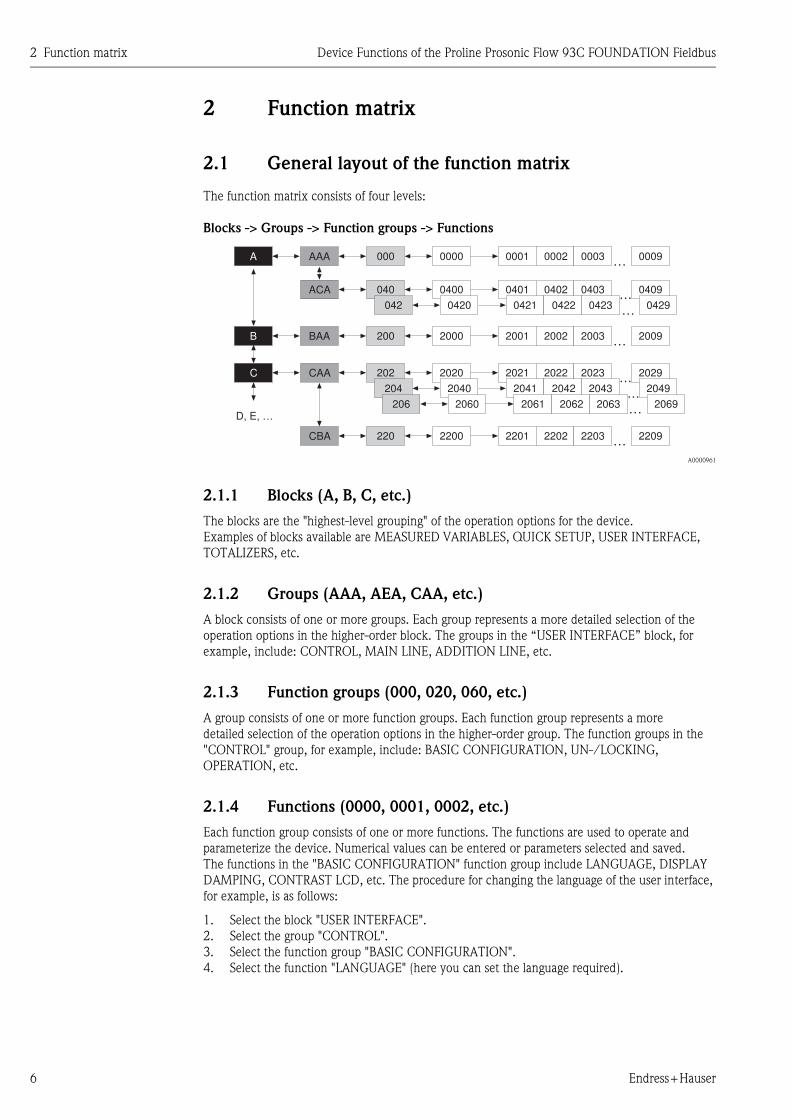
2 Function matrix
2.1 General layout of the function matrix
The function matrix consists of four levels:
Blocks -> Groups -> Function groups -> Functions
A0000961
2.1.1 Blocks (A, B, C, etc.)
The blocks are the "highest-level grouping" of the operation options for the device.
Examples of blocks available are MEASURED VARIABLES, QUICK SETUP, USER INTERFACE,
TOTALIZERS, etc.
2.1.2 Groups (AAA, AEA, CAA, etc.)
A block consists of one or more groups. Each group represents a more detailed selection of the
operation options in the higher-order block. The groups in the “USER INTERFACE” block, for
example, include: CONTROL, MAIN LINE, ADDITION LINE, etc.
2.1.3 Function groups (000, 020, 060, etc.)
A group consists of one or more function groups. Each function group represents a more
detailed selection of the operation options in the higher-order group. The function groups in the
"CONTROL" group, for example, include: BASIC CONFIGURATION, UN-/LOCKING,
OPERATION, etc.
2.1.4 Functions (0000, 0001, 0002, etc.)
Each function group consists of one or more functions. The functions are used to operate and
parameterize the device. Numerical values can be entered or parameters selected and saved.
The functions in the "BASIC CONFIGURATION" function group include LANGUAGE, DISPLAY
DAMPING, CONTRAST LCD, etc. The procedure for changing the language of the user interface,
for example, is as follows:
1. Select the block "USER INTERFACE".
2. Select the group "CONTROL".
3. Select the function group "BASIC CONFIGURATION".
4. Select the function "LANGUAGE" (here you can set the language required).
…
…
…
…
…
…
…
…
0001
2001
0401
2021
2201
0002
2002
0402
2022
2202
0003
2003
0403
2023
2203
0009
2009
0409
2029
2209
0429
2049
2069
0421
2041
0422
2042
0423
2043
20632061 2062
0000
2000
0400
2020
2200
0420
2040
2060
000
200
040
202
220
042
204
206
AAA
BAA
ACA
CAA
CBA
D, E, …
A
B
C

Device Functions of the Proline Prosonic Flow 93C FOUNDATION Fieldbus 2 Function matrix
Endress+Hauser 7
2.1.5 Codes identifying cells
Each cell (block, group, function group and function) in the function matrix has an individual,
unique code.
Blocks:
The code is a letter (A, B, C, etc.)
Groups:
The code consists of three letters (AAA, ABA, BAA, etc.).
The first letter matches the block code (i.e. each group in block A has a code starting with an A_ _;
the codes of the groups in block B start with a B _ _, and so on). The other two letters are for
identifying the group within the respective block.
Function groups:
The code consists of three digits (000, 001, 100, etc.)
Functions:
The code consists of four digits (0000, 0001, 0201, etc.).
The first three digits are the same as the code for the function group.
The last digit in the code is a counter for the functions in the function group, incrementing from 0
to 9 (e.g. function 0005 is the sixth function in group 000).
2.2 Illustration of the function descriptions
A0004822-EN
Fig. 1: Example for the description of a function
1 Name of the function
2 Number of the function (appears on the local display)
3 Description of the function
4 Selection or entry options or display
5 Factory setting (the measuring device is delivered with this setting/selected option)
Block Group Function group Functions
2000 2001 2002200CAAC
A0001251
UNIT LENGTH 0424 For selecting the unit for displaying the length of the nominal diameter.
The unit you select here is also valid for:- Nominal diameter of sensor, see Function NOMINAL DIAMETER (6804).
Options:
Factory setting:
MILLIMETERINCH
MILLIMETER
1 2 3
5 4

2 Function matrix Device Functions of the Proline Prosonic Flow 93C FOUNDATION Fieldbus
8 Endress+Hauser
2.3 Display lines on the local display
The local display is split into various display lines.
A0001253
Fig. 2: Local display
1 Main line
2 Additional line
3 Information line
The values are assigned to the individual lines in the USER INTERFACE block, → Page 19.
2.4 Function matrix of the Prosonic Flow 93C
FOUNDATION Fieldbus
BLOCKS GROUPS FUNCTION
GROUPS
MEASURED VARIABLES A → MEASURING VALUES AAA → Page 10
(→ Page 9) SYSTEM UNITS ACA → Page 12
↓
QUICK-SETUP B → Commissioning and application setups → Page 16
(→ Page 16)
↓
USER INTERFACE C → CONTROL CAA → Page 20
(→ Page 19) MAIN LINE CCA → Page 24
ADDITION LINE CEA → Page 27
↓ INFORMATION LINE CGA → Page 31
TOTALIZER D → TOTALIZER 1 DAA → Page 36
(→ Page 35) TOTALIZER 2 DAB → Page 36
↓ TOTALIZER 3 DAC → Page 36
HANDLING TOTALIZER DJA → Page 39
↓
BASIC FUNCTION G → FOUNDATION FIELDBUS GGA → Page 41
(→ Page 40)PROCESS PARAMETER (CH1 to
CH2)GIA, GIB → Page 44
SYSTEM PARAMETER (CH1 to CH2) GLA, GLB → Page 50
↓ SENSOR DATA (CH1 to CH2) GNA, GNB → Page 52
SUPERVISION J → SYSTEM JAA → Page 59
(→ Page 58) SYSTEM CH2 JAB → Page 59
VERSION INFO JCA → Page 63
Esc
E+-
1
2
3

Device F
un
ction
s of th
e Pro
line P
roso
nic F
low
93
C F
OU
ND
AT
ION
Field
bu
s3
Blo
ck M
EA
SUR
ED
VA
RIA
BLE
S
En
dress+
Hau
ser9
3B
lock
ME
ASU
RE
D V
AR
IAB
LE
S
Functions
FORMAT
DATE/TIME (0429) P. 15
UNIT
VELOCITY(0425) P. 15
FLOW VELOCAVG.
(0087) P. 11
UNIT
LENGTH(0424) P. 14
SOUND VELOC. AVG
(0086) P. 11
UNIT VOLUME(0403) P. 13
UNIT VISCOSITY
(0423) P. 14
→
→
→
SIGNAL STRENGTH CH1
(0007) P. 10
SIGNAL
STRENGTH CH2(0067) P. 10
VOLUME FLOWAVG.
(0083) P. 11
UNIT VOLUME FLOW
(0402) P. 12
UNIT
TEMPERATURE (0422)P. 14
↑↑
↑↑
↑
Function
groups
MAIN VALUES CH1
(000) P. 10
↑↓MAIN VALUES
CH2(006) P. 10
↑↓CALC.
MAIN VALUES(008) P. 11
CONFIGURATION
(040) P. 12
↑↓ADDITIONAL
CONFIGURATION(042) P. 14
↑↑
Groups
MEASURING VALUES
(AAA) P. 10
↑↓
↑↓
SYSTEM UNITS
(ACA) P. 12
↑
Block
MEASURED VARIABLES

3 Block MEASURED VARIABLES Device Functions of the Proline Prosonic Flow 93C FOUNDATION Fieldbus
10 Endress+Hauser
3.1 Group MEASURING VALUES
3.1.1 Function group MAIN VALUES CH1
3.1.2 Function group MAIN VALUES CH2
MEASURED
VARIABLESA → MEASURING VALUES
AAA→ MAIN VALUES CH1
000
Functional descriptionMEASURED VARIABLES→ MEASURING VALUES→ MAIN VALUES CH1
SIGNAL STRENGTH CH1
(0007)
The signal strength appears on the display (channel 1).
Display:
4-digit fixed point number (e.g. 80.0)
! Note!
To ensure reliable measurement takes place, Prosonic Flow requires a signal
strength of > 30.
MEASURED
VARIABLESA → MEASURING VALUES
AAA→ MAIN VALUES CH2
006
Functional descriptionMEASURED VARIABLES→ MEASURING VALUES→ MAIN VALUES CH2
SIGNAL STRENGTH CH2
(0067)
The signal strength appears on the display (channel 2).
Display:
4-digit fixed-point number
(e.g. 80.0)
! Note!
To ensure reliable measurement takes place, Prosonic Flow requires a signal
strength of > 30.

Device Functions of the Proline Prosonic Flow 93C FOUNDATION Fieldbus 3 Block MEASURED VARIABLES
Endress+Hauser 11
3.1.3 Function group CALCULATED MAIN VALUES
MEASURED
VARIABLESA → MEASURING VALUES AAA → CALC. MAIN VALUES 008
Functional descriptionMEASURED VARIABLES→ MEASURING VALUES→ CALCULATED MAIN VALUES
The calculated measured values appear on the display. The measured values of both channels are used when calculating
the values.
! Note!
� The engineering units of all the measured variables shown here can be set in the "SYSTEM UNITS" group.
� If the fluid in the pipe flows backwards, a negative sign prefixes the flow reading on the display.
VOLUME FLOW
AVERAGE
(0083)
The average volume flow appears on the display. Calculated from the measured values:
(VOLUME FLOW CH1 + VOLUME FLOW CH2) · 1/2
Display:
5-digit floating-point number, including unit and sign
(e.g. 5.5445 dm3/min; 1.4359 m3/h; –731.63 gal/d; etc.)
SOUND VELOCITY
AVERAGE
(0086)
The average sound velocity appears on the display. Calculated from the measured values:
(SOUND VELOCITY CH1 + SOUND VELOCITY CH2) · 1/2
Display:
5-digit fixed-point number, incl. units
(e.g. 1400.0 m/s, 5249.3 ft/s)
FLOW
VELOCITY AVERAGE
(0087)
The average flow velocity appears on the display. Calculated from the measured values:
(FLOW VEL. CH1 + FLOW VEL. CH2) · 1/2
Display:
5-digit floating-point number, including unit and sign
(e.g. 8.0000 m/s, 26.247 ft/s)

3 Block MEASURED VARIABLES Device Functions of the Proline Prosonic Flow 93C FOUNDATION Fieldbus
12 Endress+Hauser
3.2 SYSTEM UNITS groups
3.2.1 Function group CONFIGURATION
MEASURED
VARIABLESA → MEASURING VALUES
AAA
↓
SYSTEM UNITS ACA → CONFIGURATION 040
Functional descriptionMEASURED VARIABLES→ SYSTEM UNITS→ CONFIGURATION
You can select the units for measured variables in this function group.
! Note!
The units selected here have no effect on the FOUNDATION Fieldbus. They are only used for the local display and for
assigned instrument functions.
UNIT VOLUME FLOW
(0402)
Use this function to select the unit for displaying the volume flow.
The unit you select here is also valid for:
� Simulation
� Low flow cut off
Options:
! Note!
The following units of time (…) can be selected:
s = second, m = minute, h = hour, d = day
Metric:
Cubic centimeter → cm³/…
Cubic decimeter → dm³/…
Cubic meter → m³/…
Milliliter → ml/…
Liter → l/…
Hectoliter → hl/…
Megaliter → Ml/… MEGA
US:
Cubic centimeter → cc/…
Acre foot → af/…
Cubic foot → ft³/…
Fluid ounce → oz f/…
Gallon → US gal/…
Million gallon → US Mgal/…
Barrel (normal fluids: 31.5 gal/bbl) → US bbl/… NORM.
Barrel (beer: 31.0 gal/bbl) → US bbl/… BEER
Barrel (petrochemicals: 42.0 gal/bbl) → US bbl/… PETR.
Barrel (filling tanks: 55.0 gal/bbl) → US bbl/… TANK
Imperial:
Gallon → imp. gal/…
Mega gallon → imp. Mgal/…
Barrel (beer: 36.0 gal/bbl) → imp. bbl/… BEER
Barrel (petrochemicals: 34.97 gal/bbl) → imp. bbl/… PETR.
Factory setting:
Depends on country (dm³/m...m³/h or US gal/m...US Mgal/d)

Device Functions of the Proline Prosonic Flow 93C FOUNDATION Fieldbus 3 Block MEASURED VARIABLES
Endress+Hauser 13
UNIT VOLUME
(0403)
Use this function to select the unit for displaying the volume.
Options:
Metric:
Cubic centimeter → cm³
Cubic decimeter → dm³
Cubic meter → m³
Milliliter → ml
Liter → lHectoliter → hl
Megaliter → Ml MEGA
US:
Cubic centimeter → cc
Acre foot → af
Cubic foot → ft³Fluid ounce → oz f
Gallon → US gal
Million gallon → US Mgal
Barrel (normal fluids: 31.5 gal/bbl) → US bbl NORM.FL.
Barrel (beer: 31.0 gal/bbl) → US bbl BEER
Barrel (petrochemicals: 42.0 gal/bbl) → US bbl PETROCH.
Barrel (filling tanks: 55.0 gal/bbl) → US bbl TANK
Imperial:
Gallon → imp. gal
Mega gallon → imp. Mgal
Barrel (beer: 36.0 gal/bbl) → imp. bbl BEER
Barrel (petrochemicals: 34.97 gal/bbl) → imp. bbl PETROCH.
Factory setting:
Depends on country (dm³...m³ or US gal...US Mgal) → Page 65 ff.
! Note!
� The unit of the totalizers is independent of your choice here. The unit for each
totalizer is selected separately for the totalizer in question.
� The unit selected in this function is only for showing the values on the local display,
i.e. the measuring system does not use it for further processing of the measured
variables.
Functional descriptionMEASURED VARIABLES→ SYSTEM UNITS→ CONFIGURATION

3 Block MEASURED VARIABLES Device Functions of the Proline Prosonic Flow 93C FOUNDATION Fieldbus
14 Endress+Hauser
3.2.2 Function group ADDITIONAL CONFIGURATION
MEASURED
VARIABLESA → MEASURING VALUES
AAA
↓
SYSTEM UNITS ACA → CONFIGURATION 040
↓
ADDITIONAL
CONFIGURATION
042
Functional descriptionMEASURED VARIABLES→ SYSTEM UNITS→ ADDITIONAL CONFIGURATION
! Note!
The units selected here have no effect on the FOUNDATION Fieldbus. They are only used for the local display and for
assigned instrument functions.
UNIT TEMPERATURE
(0422)
Use this function to select the unit for displaying the fluid temperature.
! Note!
The fluid temperature is entered in the TEMPERATURE function (→ Page 47).
Options:
°C (Celsius)
K (Kelvin)
°F (Fahrenheit)
R (Rankine)
Factory setting:
Depends on country (°C or °F) → Page 65 ff.
UNIT VISCOSITY
(0423)
Use this function to select the unit for fluid viscosity.
! Note!
The viscosity is entered in the function (→ Page 48).
Options:
mm2/s
cSt
St
Factory setting:
mm2/s
UNIT LENGTH (0424) Use this function to select the unit for the measure of length.
The unit you select here is valid for:
� Nominal diameter
� Diameter
� Wall thickness
Options:
MILLIMETER
INCH
Factory setting:
Depends on country (MILLIMETER or INCH)

Device Functions of the Proline Prosonic Flow 93C FOUNDATION Fieldbus 3 Block MEASURED VARIABLES
Endress+Hauser 15
UNIT VELOCITY
(0425)
Use this function to select the unit for displaying the velocity.
The unit you select here is also valid for:
� Sound velocity
� Flow velocity
Options:
m/s
ft/s
Factory setting:
m/s
FORMAT DATE/TIME
(0429)
Use this function to select the date and time format of the calibration history.
Options:
DD.MM.YY 24 H
MM/DD/YY 12 H A/P
DD.MM.YY 12 H A/P
MM/DD/YY 24 H
Factory setting:
DD.MM.YY 24 H
Functional descriptionMEASURED VARIABLES→ SYSTEM UNITS→ ADDITIONAL CONFIGURATION

4 Block QUICK-SETUP Device Functions of the Proline Prosonic Flow 93C FOUNDATION Fieldbus
16 Endress+Hauser
4 Block QUICK-SETUP
Block GroupFunction
groupsFunctions
QUICK-SETUP
(B)→ →
QS-COMMISSION.
(1002) P. 16→
T-DAT SAVE/LOAD
(1009) P. 16
Functional descriptionQUICK-SETUP
SETUP
COMMISSIONING
(1002)
Use this function to start the Quick Setup menu for commissioning.
Options:
YES
NO
Factory setting:
NO
! Note!
You will find a flowchart of the "COMMISSIONING" Quick Setup menu on Page 17.
Please refer to the Operating Instructions for Prosonic Flow 93C FOUNDATION
Fieldbus, BA00154D, for more information on Quick Setup menus.
T-DAT SAVE/LOAD
(1009)
Use this function to save the parameter settings / configuration of the transmitter in a
transmitter DAT (T-DAT), or to load the parameter settings from the T-DAT into the
EEPROM (manual security function).
Application examples:
� After commissioning, the current measuring point parameters can be saved to the T-
DAT as a backup.
� If the transmitter is replaced for some reason, the data from the T-DAT can be loaded
into the new transmitter (EEPROM).
Options:
CANCEL
SAVE (from EEPROM to T-DAT)
LOAD (from the T-DAT into EEPROM)
Factory setting:
CANCEL
! Note!
� If the power supply fails, the totalizer readings are automatically saved to the
EEPROM.
� The option "LOAD" cannot be executed if the T-DAT is empty or faulty.
� The option "LOAD" and "SAVE" cannot be executed if no T-DAT is present.

Device Functions of the Proline Prosonic Flow 93C FOUNDATION Fieldbus 4 Block QUICK-SETUP
Endress+Hauser 17
4.1 Quick Setup
In the case of measuring devices without a local display, the individual parameters and functions
must be configured via the operating program, e.g. FieldCare.
If the measuring device is equipped with a local display, all the important device parameters for
standard operation, as well as additional functions, can be configured quickly and easily by means
of the following Quick Setup menus.
4.1.1 Quick Setup "Commissioning"
a0008715-en
Note!
� The display returns to the function SETUP COMMISSIONING (1002) if you press the ESC key
combination during parameter interrogation.
� The "Commissioning" Quick Setup must be carried out before one of the Quick Setups explained
below is run.
m The "DELIVERY SETTINGS" option sets every selected unit to the factory setting.
The "ACTUAL SETTINGS" accepts the units you configured beforehand.
n Only units not yet configured in the current Quick Setup are offered for selection in each cycle. The volume unit is
derived from the volume flow unit.
o The "YES" option remains visible until all the units have been configured.
"NO" is the only option displayed when no further units are available.
p The "automatic parameterization of the display" option contains the following basic settings/factory settings
YES Main line = volume flow
Additional line = Totalizer 1
Information line = Operating/system condition
NO The existing (selected) settings remain.
q The execution of other Quick Setups is described in the following sections.
++ +E E
0424 042504230402 0422
1002B
2000
Esc
E+-
XXX.XXX.XX
HOME-POSITION
n
o
m
p
q
UnitVolume Flow
UnitTemperature
UnitViscosity
UnitLength
UnitVelocity
QSCommission.
Language
Presetting
Quick Setup
System Units
Volume Viscosity Length Velocity Quit
Configure another unit? NOYES
Selection system units
Autom. configuration display?
Another quick setup?
NO
NO
Automatical parameterizationof the display
YES
Temperature
Deliver Settingsy
Selection pre-settings
Actual Settings

4 Block QUICK-SETUP Device Functions of the Proline Prosonic Flow 93C FOUNDATION Fieldbus
18 Endress+Hauser
4.1.2 Data backup/transmission
Using the T-DAT SAVE/LOAD function, you can transfer data (device parameters and settings)
between the T-DAT (exchangeable memory) and the EEPROM (device storage unit).
This is required in the following instances:
� Creating a backup: current data are transferred from an EEPROM to the T-DAT.
� Replacing a transmitter: current data are copied from an EEPROM to the T-DAT and then
transferred to the EEPROM of the new transmitter.
� Duplicating data: current data are copied from an EEPROM to the T-DAT and then transferred to
EEPROMs of identical measuring points.
! Note!
For information on installing and removing the T-DAT, see Operating Instructions for Prosonic Flow
93C FOUNDATION Fieldbus, BA00145D.
a0001221-en
Fig. 3: Data backup/transmission with T-DAT SAVE/LOAD function
Information on the LOAD and SAVE options available:
LOAD: Data are transferred from the T-DAT to the EEPROM.
! Note!
� Any settings already saved on the EEPROM are deleted.
� This option is only available, if the T-DAT contains valid data.
� This option can only be executed if the software version of the T-DAT is the same or newer than
that of the EEPROM. Otherwise, the error message "TRANSM. SW-DAT" appears after restarting
and the LOAD function is then no longer available.
SAVE:
Data are transferred from the EEPROM to the T-DAT
FEsc
E+-
XXX.XXX.XX
F F
FF FF
P P
PP
N
O
T-DATSAVE/LOAD
Quick Setup
HOMEPOSITION
LOAD
YES NO
CANCELSAVE
YES NO
Restart of themeasuring device
Input issaved

Device F
un
ction
s of th
e Pro
line P
roso
nic F
low
93
C F
OU
ND
AT
ION
Field
bu
s5
Blo
ck U
SER
INT
ER
FA
CE
En
dress+
Hau
ser19
5B
lock
USE
R IN
TE
RFA
CE
Functions
XLINE CALC. M. VAL.
(2009) P. 21
BACKLIGHT
(2004) P. 21
ACCESS CODE
CNTR(2023) P. 21
DISPLAY MODE
(2403) P. 28
DISPLAY MODE
(2423) P. 30
DISPLAY MODE
(2603) P. 32
DISPLAY MODE
(2623) P. 34
CONTRASTLCD
(2003) P. 21
STATUS ACCESS(2022) P. 22
FORMAT
(2202) P. 25
FORMAT
(2222) P. 26
FORMAT
(2402) P. 28
FORMAT
(2422) P. 30
FORMAT
(2602) P. 32
FORMAT
(2622) P. 34
DISPLAY DAMPING
(2002) P. 20
DEFINE PRIVATE
CODE(2021) P. 22
100% VALUE
(2201) P. 24
100% VALUE
(2221) P. 26
100% VALUE
(2401) P. 27
100% VALUE
(2421) P. 29
100% VALUE
(2601) P. 32
100% VALUE
(2621) P. 33
→
→
→
→
→
→
→
→
LANGUAGE
(2000) P. 20
ACCESS CODE(2020) P. 22
TEST DISPLAY
(2040) P. 23
ASSIGN
(2200) P. 24
ASSIGN
(2220) P. 26
ASSIGN
(2400) P. 27
ASSIGN
(2420) P. 29
ASSIGN
(2600) P. 31
ASSIGN
(2620) P. 33
↑↑
↑↑
↑↑
↑↑
↑
Function
groups
BASIC CONFIGURATION
(200) P. 23
↑↓UNLOCKING/LO
CKING(202) P. 22
↑↓OPERATION
(204) P. 23
CONFIGURATION
(220) P. 24
↑↓MULTIPLEX
(222) P. 26
CONFIGURATION
(240) P. 27
↑↓MULTIPLEX
(242) P. 29
CONFIGURATION
(260) P. 31
↑↓MULTIPLEX
(262) P. 33
↑↑
↑↑
Groups
CONTROL
(CAA) P. 20
↑↓
↑↓MAIN LINE
(CCA) P. 24
↑↓
↑↓ADDITION LINE
(CEA) P. 27
↑↓
↑↓INFORMATION
LINE(CGA) P. 31
↑
Block
USER INTERFACE
(C)

5 Block USER INTERFACE Device Functions of the Proline Prosonic Flow 93C FOUNDATION Fieldbus
20 Endress+Hauser
5.1 Group CONTROL
5.1.1 Function group BASIC CONFIGURATION
USER INTERFACE C → CONTROL CAA → BASIC CONFIGURATION 200
Functional descriptionUSER INTERFACE → CONTROL → BASIC CONFIGURATION
LANGUAGE
(2000)
Use this function to select the language for all texts, parameters and messages shown on
the local display.
! Note!
The displayed options depend on the available language group shown in the LANGUAGE
GROUP function (8226).
Options:
Language group
WEST EU / USA
Language group
EAST EU / SCAND.
Language group ASIA
Language group
CHINESE
ENGLISH
DEUTSCH
FRANCAIS
ESPANOL
ITALIANO
NEDERLANDS
PORTUGUESE
ENGLISH
NORSK
SVENSKA
SUOMI
POLISH
CZECH
RUSSIAN
ENGLISH
BAHASA INDONESIA
JAPANESE (syllabary)
CHINESE
ENGLISH
Factory setting:
Depends on country → Page 65
! Note!
� If you press the P keys simultaneously when starting, the language is set to
ENGLISH.
� You can change the language group via the configuration software FieldCare.
Please do not hesitate to contact your Endress+Hauser sales office if you have any
questions.
DISPLAY DAMPING
(2002)
Use this function to enter a time constant defining how the display reacts to severely
fluctuating flow variables, either very quickly (enter a low time constant) or with
damping (enter a high time constant).
User input:
0 to 100 seconds
Factory setting:
1 s
! Note!
Setting the time constant to zero seconds switches off damping.

Device Functions of the Proline Prosonic Flow 93C FOUNDATION Fieldbus 5 Block USER INTERFACE
Endress+Hauser 21
CONTRAST LCD
(2003)
Use this function to optimize display contrast to suit local operating conditions.
User input:
10…100%
Factory setting:
50%
BACKLIGHT
(2004)
Use this function to optimize the backlight to suit local operating conditions.
User input:
10…100%
Factory setting:
50%
X-LINE CALCULATED
MAIN VALUES
(2009)
This function defines which calculated main value from the measured values of both
channels is displayed. The option CALCULATED VOLUME FLOW must be selected in
the ASSIGN function (2200, main line), (2400, additional line), (2600, information line)
so that the value appears in the line desired.
Options:
(CH1 + CH2)/2
Factory setting:
(CH1 + CH2)/2
Functional descriptionUSER INTERFACE → CONTROL → BASIC CONFIGURATION

5 Block USER INTERFACE Device Functions of the Proline Prosonic Flow 93C FOUNDATION Fieldbus
22 Endress+Hauser
5.1.2 Function group UNLOCKING/LOCKING
USER INTERFACE C → CONTROL CAA → BASIC CONFIGURATION 200
↓
UNLOCKING/LOCKING 202
Functional descriptionDISPLAY → CONTROL → UNLOCKING/LOCKING
ACCESS CODE
(2020)
All data of the measuring system are protected against inadvertent change. Programming
is disabled and the settings cannot be changed until a code is entered in this function. If
you press the OS keys in any function, the measuring system automatically goes to this
function and the prompt to enter the code appears on the display (when programming is
disabled).
You can enable programming by entering your personal code (factory setting = 93, see
DEF.PRIVATE CODE (2021)) .
User input:
Max. 4-digit number: 0 to 9999
! Note!
� The programming levels are disabled if you do not press a key within 60 seconds
following automatic return to the HOME position.
� You can also disable programming in this function by entering any number (other than
the defined private code).
� The Endress+Hauser service organization can be of assistance if you mislay your
personal code.
� In this function, access to programming is only valid for local configuration. If
functions or parameters are to be changed via the FOUNDATION Fieldbus,
programming must be enabled separately in the parameter "Un/Locking - Access
Code" (Transducer Blocks).
DEF. PRIVATE CODE
(2021)
Use this function to specify a personal code number for enabling programming in the
ACCESS CODE function.
User input:
0 to 9999 (max. 4-digit number)
Factory setting:
93
! Note!
� Programming is always enabled with the code "0".
� Programming has to be enabled before this code can be changed. When programming
is disabled this function is not available, thus preventing others from accessing your
personal code.
STATUS ACCESS
(2022)
Use this function to check the access status for the function matrix.
Display:
ACCESS CUSTOMER (parameterization enabled)
LOCKED (parameterization disabled)
ACCESS CODE
COUNTER
(2023)
The number of times the private or service code was entered to access the device appears
on the display.
Display:
Integer (delivery status: 0)

Device Functions of the Proline Prosonic Flow 93C FOUNDATION Fieldbus 5 Block USER INTERFACE
Endress+Hauser 23
5.1.3 Function group OPERATION
USER INTERFACE C → CONTROL CAA → BASIC CONFIGURATION 200
↓
UNLOCKING/LOCKING 202
↓
OPERATION 204
Functional descriptionUSER INTERFACE → CONTROL → OPERATION
TEST DISPLAY
(2040)
Use this function to test the operability of the local display and its pixels.
Options:
OFF
ON
Factory setting:
OFF
Test sequence:
1. Start the test by selecting ON.
2. All pixels of the main line, additional line and information line are darkened for
minimum 0.75 seconds.
3. Main line, additional line and information line show an "8" in each field for minimum
0.75 seconds.
4. Main line, additional line and information line show a "0" in each field for minimum
0.75 seconds.
5. Main line, additional line and information line show nothing (blank display) for
minimum 0.75 seconds.
When the test completes the local display returns to its initial state and the setting
changes to OFF.

5 Block USER INTERFACE Device Functions of the Proline Prosonic Flow 93C FOUNDATION Fieldbus
24 Endress+Hauser
5.2 Group MAIN LINE
5.2.1 Function group CONFIGURATION
USER INTERFACE C → CONTROL CAA
↓
MAIN LINE CCA → CONFIGURATION 220
Functional descriptionDISPLAY→ MAIN LINE → CONFIGURATION
1 = Main line
2 = Additional line
3 = Information line
A0001253
ASSIGN
(2200)
Use this function to define the display value assigned to the main line (the top line of the
local display) during normal measuring operation.
Options:
OFF
CALCULATED VOLUME FLOW
CALCULATED VOLUME FLOW IN %
SOUND VELOCITY AVERAGE
SIGNAL STRENGTH (CH1 to CH2)
FLOW VELOCITY AVERAGE
TOTALIZER 1 TO 3
AI1 to AI8 - OUT VALUE
PID - IN VALUE (controlled variable)
PID - CAS IN VALUE (external set point)
PID - OUT VALUE (manipulated variable)
! Note!
If a channel is not visible, it does not appear in the options. Channels can be displayed or
hidden by means of the MEASUREMENT function (6880).
Factory setting:
CALCULATED VOLUME FLOW
100% VALUE
(2201) ! Note!
This function is not available unless the CALCULATED VOLUME FLOW IN % setting
was selected in the ASSIGN function (2200).
Use this function to define the flow value to be shown on the display as the 100% value.
User input:
5-digit floating-point number
Factory setting:
Depends on nominal diameter and country [700 to 27800 m3/hr or
3100 to 44500 imp.gal/min. or 81 to 176 imp.Mgal/day] → Page 65.
Esc
E+-
1
2
3

Device Functions of the Proline Prosonic Flow 93C FOUNDATION Fieldbus 5 Block USER INTERFACE
Endress+Hauser 25
FORMAT
(2202)
Use this function to define the maximum number of places after the decimal point
displayed for the reading in the main line.
Options:
XXXXX. – XXXX.X – XXX.XX – XX.XXX – X.XXXX
Factory setting:
X.XXXX
! Note!
� Note that this setting only affects the reading as it appears on the display, it has no
influence on the accuracy of the system's calculations.
� The places after the decimal point as computed by the measuring device cannot
always be displayed, depending on this setting and the engineering unit. In such
instances an arrow appears on the display between the measuring value and the
engineering unit (e.g. 1.2 → m3/h), indicating that the measuring system is
computing with more decimal places than can be shown on the display.
Functional descriptionDISPLAY→ MAIN LINE → CONFIGURATION

5 Block USER INTERFACE Device Functions of the Proline Prosonic Flow 93C FOUNDATION Fieldbus
26 Endress+Hauser
5.2.2 Function group MULTIPLEX
USER INTERFACE C → CONTROL CAA
↓
MAIN LINE CCA → CONFIGURATION 220
↓
MULTIPLEX 222
Functional descriptionUSER INTERFACE → MAIN LINE → MULTIPLEX
ASSIGN
(2220)
Use this function to define a second reading to be displayed in the main line alternatively
(every 10 seconds) with the reading defined in the ASSIGN function (2200).
Options:
OFF
CALCULATED VOLUME FLOW
CALCULATED VOLUME FLOW IN %
SOUND VELOCITY AVERAGE
SIGNAL STRENGTH (CH1 to CH2)
FLOW VELOCITY AVERAGE
TOTALIZER 1 TO 3
AI1 to AI8 - OUT VALUE
PID - IN VALUE (controlled variable)
PID - CAS IN VALUE (external set point)
PID - OUT VALUE (manipulated variable)
! Note!
If a channel is not visible, it does not appear in the options. Channels can be displayed or
hidden by means of the MEASUREMENT function (6880).
Factory setting:
OFF
100% VALUE
(2221) ! Note!
This function is not available unless the CALCULATED VOLUME FLOW IN % setting
was selected in the ASSIGN function (2200).
Use this function to define the flow value to be shown on the display as the 100% value.
User input:
5-digit floating-point number
Factory setting:
Depends on nominal diameter and country [700 to 27800 m3/hr or
3100 to 44500 imp.gal/min. or 81 to 176 imp.Mgal/day] → Page 65.
FORMAT
(2222)
Use this function to define the maximum number of places after the decimal point for the
second value displayed in the main line.
Options:
XXXXX. – XXXX.X – XXX.XX – XX.XXX – X.XXXX
Factory setting:
X.XXXX
! Note!
� Note that this setting only affects the reading as it appears on the display, it has no
influence on the accuracy of the system's calculations.
� The places after the decimal point as computed by the measuring device cannot
always be displayed, depending on this setting and the engineering unit. In such
instances an arrow appears on the display between the measuring value and the
engineering unit (e.g. 1.2 → m3/h), indicating that the measuring system is
computing with more decimal places than can be shown on the display.

Device Functions of the Proline Prosonic Flow 93C FOUNDATION Fieldbus 5 Block USER INTERFACE
Endress+Hauser 27
5.3 Group ADDITION LINE
5.3.1 Function group CONFIGURATION
USER INTERFACE C → CONTROL CAA
↓
MAIN LINE CCA
↓
ADDITION LINE CEA → CONFIGURATION 240
Functional descriptionDISPLAY→ ADDITIONAL LINE→ CONFIGURATION
1 = Main line
2 = Additional line
3 = Information line
A0001253
ASSIGN
(2400)
Use this function to define the display value assigned to the additional line (the middle
line of the local display) during normal measuring operation.
Options:
OFF
CALCULATED VOLUME FLOW
CALCULATED VOLUME FLOW IN %
SOUND VELOCITY AVERAGE
SIGNAL STRENGTH (CH1 to CH2)
FLOW VELOCITY AVERAGE
CALCULATED VOLUME FLOW BARGRAPH %
SIGNAL STRENGTH BARGRAPH % (CH1 to CH2)
TOTALIZER (1 to 3)
FLOW DIRECTION (CH1 to CH2)
CALCULATED FLOW DIRECTION
AI1 to AI8 - OUT VALUE
PID - IN VALUE (controlled variable)
PID - CAS IN VALUE (external set point)
PID - OUT VALUE (manipulated variable)
DEVICE PD-TAG (tag name)
Factory setting:
TOTALIZER 1
! Note!
If a channel is not visible, it does not appear in the options. Channels can be displayed or
hidden by means of the MEASUREMENT function (6880).
100% VALUE
(2401) ! Note!
This function is not available unless one of the following was selected in the ASSIGN
function (2400):
� CALCULATED VOLUME FLOW IN %
� CALCULATED VOLUME FLOW BARGRAPH %
Use this function to define the flow value to be shown on the display as the 100% value.
User input:
5-digit floating-point number
Factory setting:
Depends on nominal diameter and country [700 to 27800 m3/hr or
3100 to 44500 imp.gal/min. or 81 to 176 imp.Mgal/day] → Page 65.
Esc
E+-
1
2
3

5 Block USER INTERFACE Device Functions of the Proline Prosonic Flow 93C FOUNDATION Fieldbus
28 Endress+Hauser
FORMAT
(2402) ! Note!
This function is not available unless a number was selected in the ASSIGN function
(2400).
Use this function to define the maximum number of places after the decimal point
displayed for the reading in the additional line.
Options:
XXXXX. – XXXX.X – XXX.XX – XX.XXX – X.XXXX
Factory setting:
X.XXXX
! Note!
� Note that this setting only affects the reading as it appears on the display, it has no
influence on the accuracy of the system's calculations.
� The places after the decimal point as computed by the measuring device cannot
always be displayed, depending on this setting and the engineering unit. In such
instances an arrow appears on the display between the measuring value and the
engineering unit (e.g. 1.2 → m3/h), indicating that the measuring system is
computing with more decimal places than can be shown on the display.
DISPLAY MODE
(2403) ! Note!
This function is not available unless the CALCULATED VOLUME FLOW BARGRAPH IN
% or SIGNAL STRENGTH BAR GRAPH setting was selected in the ASSIGN function
(2420).
Use this function to define the format of the bar graph.
Options:
STANDARD (Simple bar graph with 25 / 50 / 75% gradations and integrated sign).
A0001258
SYMMETRY (Symmetrical bar graph for positive and negative directions of flow, with
–50 / 0 / +50% gradations and integrated sign).
A0001259
Factory setting:
STANDARD
Functional descriptionDISPLAY→ ADDITIONAL LINE→ CONFIGURATION

Device Functions of the Proline Prosonic Flow 93C FOUNDATION Fieldbus 5 Block USER INTERFACE
Endress+Hauser 29
5.3.2 Function group MULTIPLEX
USER INTERFACE C → CONTROL CAA
↓
MAIN LINE CCA
↓
ADDITION LINE CEA → CONFIGURATION 240
↓
MULTIPLEX 242
Functional descriptionUSER INTERFACE → ADDITION LINE → MULTIPLEX
ASSIGN
(2420)
Use this function to define a second reading to be displayed in the additional line
alternatively (every 10 seconds) with the reading defined in the ASSIGN function (2400).
Options:
OFF
CALCULATED VOLUME FLOW
CALCULATED VOLUME FLOW IN %
SOUND VELOCITY AVERAGE
SIGNAL STRENGTH (CH1 to CH2)
FLOW VELOCITY AVERAGE
CALCULATED VOLUME FLOW BARGRAPH %
SIGNAL STRENGTH BARGRAPH % (CH1 to CH2)
TOTALIZER (1 to 3)
CALCULATED FLOW DIRECTION
AI1 to AI8 - OUT VALUE
PID - IN VALUE (controlled variable)
PID - CAS IN VALUE (external set point)
PID - OUT VALUE (manipulated variable)
DEVICE PD-TAG (tag name)
Factory setting:
OFF
! Note!
� Multiplex mode is suspended as soon as a fault / notice message is generated.
� If a channel is not visible, it does not appear in the options. Channels can be displayed
or hidden by means of the MEASUREMENT function (6880).
100% VALUE
(2421) ! Note!
This function is not available unless one of the following was selected in the ASSIGN
function (2420):
� CALCULATED VOLUME FLOW IN %
� CALCULATED VOLUME FLOW BARGRAPH %
Use this function to define the flow value to be shown on the display as the 100% value.
User input:
5-digit floating-point number
Factory setting
Depends on nominal diameter and country [700 to 27800 m3/hr or
3100 to 44500 imp.gal/min. or 81 to 176 imp.Mgal/day] → Page 65.

5 Block USER INTERFACE Device Functions of the Proline Prosonic Flow 93C FOUNDATION Fieldbus
30 Endress+Hauser
FORMAT
(2422) ! Note!
This function is not available unless a number was selected in the ASSIGN function
(2420).
Use this function to define the maximum number of places after the decimal point for the
second value displayed in the additional line.
Options:
XXXXX. – XXXX.X – XXX.XX – XX.XXX – X.XXXX
Factory setting:
X.XXXX
! Note!
� Note that this setting only affects the reading as it appears on the display, it has no
influence on the accuracy of the system's calculations.
� The places after the decimal point as computed by the measuring device cannot
always be displayed, depending on this setting and the engineering unit. In such
instances an arrow appears on the display between the measuring value and the
engineering unit (e.g. 1.2 m3/h), indicating that the measuring system is computing
with more decimal places than can be shown on the display.
DISPLAY MODE
(2423) ! Note!
This function is not available unless the CALCULATED VOLUME FLOW BARGRAPH IN
% or SIGNAL STRENGTH BAR GRAPH setting was selected in the ASSIGN function
(2420).
Use this function to define the format of the bar graph.
Options:
STANDARD (Simple bar graph with 25 / 50 / 75% gradations and integrated sign).
A0001258
SYMMETRY (Symmetrical bar graph for positive and negative directions of flow, with
–50 / 0 / +50% gradations and integrated sign).
A0001259
Factory setting:
STANDARD
Functional descriptionUSER INTERFACE → ADDITION LINE → MULTIPLEX

Device Functions of the Proline Prosonic Flow 93C FOUNDATION Fieldbus 5 Block USER INTERFACE
Endress+Hauser 31
5.4 Group INFORMATION LINE
5.4.1 Function group CONFIGURATION
USER INTERFACE C → CONTROL CAA
↓
MAIN LINE CCA
↓
ADDITION LINE CEA
↓
INFORMATION LINE CGA → CONFIGURATION 260
Functional descriptionDISPLAY→ INFORMATION LINE→ CONFIGURATION
1 = Main line
2 = Additional line
3 = Information line
A0001253
ASSIGN
(2600)
Use this function to define the display value assigned to the information line (the bottom
line of the local display) during normal measuring operation.
Options:
OFF
CALCULATED VOLUME FLOW
CALCULATED VOLUME FLOW IN %
SOUND VELOCITY AVERAGE
SIGNAL STRENGTH (CH1 to CH2)
FLOW VELOCITY AVERAGE
CALCULATED VOLUME FLOW BARGRAPH %
SIGNAL STRENGTH BARGRAPH % (CH1 to CH2)
TOTALIZER (1 to 3)
OPERATING/SYSTEM CONDITIONS
CALCULATED FLOW DIRECTION
AI1 to AI8 - OUT VALUE
PID - IN VALUE (controlled variable)
PID - CAS IN VALUE (external set point)
PID - OUT VALUE (manipulated variable)
DEVICE PD-TAG (tag name)
Factory setting:
OPERATING/SYSTEM CONDITIONS
! Note!
If a channel is not visible, it does not appear in the options. Channels can be displayed or
hidden by means of the MEASUREMENT function (6880).
Esc
E+-
1
2
3

5 Block USER INTERFACE Device Functions of the Proline Prosonic Flow 93C FOUNDATION Fieldbus
32 Endress+Hauser
100% VALUE
(2601) ! Note!
This function is not available unless one of the following was selected in the ASSIGN
function (2400):
� CALCULATED VOLUME FLOW IN %
� CALCULATED VOLUME FLOW BARGRAPH %
Use this function to define the flow value to be shown on the display as the 100% value.
User input:
5-digit floating-point number
Factory setting:
Depends on nominal diameter and country [700 to 27800 m3/hr or
3100 to 44500 imp.gal/min. or 81 to 176 imp.Mgal/day] → Page 65.
FORMAT
(2602) ! Note!
This function is not available unless a number was selected in the ASSIGN function
(2600).
Use this function to define the maximum number of places after the decimal point
displayed for the reading in the information line.
Options:
XXXXX. – XXXX.X – XXX.XX – XX.XXX – X.XXXX
Factory setting:
X.XXXX
! Note!
� Note that this setting only affects the reading as it appears on the display, it has no
influence on the accuracy of the system's calculations.
� The places after the decimal point as computed by the measuring device cannot
always be displayed, depending on this setting and the engineering unit. In such
instances an arrow appears on the display between the measuring value and the
engineering unit (e.g. 1.2 → m3/h), indicating that the measuring system is
computing with more decimal places than can be shown on the display.
DISPLAY MODE
(2603) ! Note!
This function is not available unless the CALCULATED VOLUME FLOW BARGRAPH
IN % or SIGNAL STRENGTH BAR GRAPH setting was selected in the ASSIGN function
(2600).
Use this function to define the format of the bar graph.
Options:
STANDARD (Simple bar graph with 25 / 50 / 75% gradations and integrated sign).
A0001258
SYMMETRY (Symmetrical bar graph for positive and negative directions of flow, with
–50 / 0 / +50% gradations and integrated sign).
A0001259
Factory setting:
STANDARD
Functional descriptionDISPLAY→ INFORMATION LINE→ CONFIGURATION

Device Functions of the Proline Prosonic Flow 93C FOUNDATION Fieldbus 5 Block USER INTERFACE
Endress+Hauser 33
5.4.2 Function group MULTIPLEX
USER INTERFACE C → CONTROL CAA
↓
MAIN LINE CCA
↓
ADDITION LINE CEA
↓
INFORMATION LINE CGA → CONFIGURATION 260
↓
MULTIPLEX 262
Functional descriptionUSER INTERFACE → INFORMATION LINE → MULTIPLEX
ASSIGN
(2620)
Use this function to define a second reading to be displayed in the information line
alternatively (every 10 seconds) with the reading defined in the ASSIGN function (2600).
Options:
OFF
CALCULATED VOLUME FLOW
CALCULATED VOLUME FLOW IN %
SOUND VELOCITY AVERAGE
FLOW VELOCITY AVERAGE
CALCULATED VOLUME FLOW BARGRAPH % (CH1 to CH2)
SIGNAL STRENGTH BARGRAPH % (CH1 to CH2)
TOTALIZER (1 to 3)
OPERATING/SYSTEM CONDITIONS
FLOW DIRECTION (CH1 to CH2)
CALCULATED FLOW DIRECTION
AI1 to AI8 - OUT VALUE
PID - IN VALUE (controlled variable)
PID - CAS IN VALUE (external set point)
PID - OUT VALUE (manipulated variable)
DEVICE PD-TAG (tag name)
Factory setting:
OFF
! Note!
� Multiplex mode is suspended as soon as a fault / notice message is generated.
� If a channel is not visible, it does not appear in the options. Channels can be displayed
or hidden by means of the MEASUREMENT function (6880).
100% VALUE
(2621) ! Note!
This function is not available unless one of the following was selected in the ASSIGN
function (2400):
� CALCULATED VOLUME FLOW IN %
� CALCULATED VOLUME FLOW BARGRAPH %
Use this function to define the flow value to be shown on the display as the 100% value.
User input:
5-digit floating-point number
Factory setting:
Depends on nominal diameter and country [700 to 27800 m3/hr or
3100 to 44500 imp.gal/min. or 81 to 176 imp.Mgal/day] → Page 65.

5 Block USER INTERFACE Device Functions of the Proline Prosonic Flow 93C FOUNDATION Fieldbus
34 Endress+Hauser
FORMAT
(2622) ! Note!
This function is not available unless a number was selected in the ASSIGN function
(2600).
Use this function to define the maximum number of places after the decimal point for the
second value displayed in the information line.
Options:
XXXXX. – XXXX.X – XXX.XX – XX.XXX – X.XXXX
Factory setting:
X.XXXX
! Note!
� Note that this setting only affects the reading as it appears on the display, it has no
influence on the accuracy of the system's calculations.
� The places after the decimal point as computed by the measuring device cannot
always be displayed, depending on this setting and the engineering unit. In such
instances an arrow appears on the display between the measuring value and the
engineering unit (e.g. 1.2 → m3/h), indicating that the measuring system is
computing with more decimal places than can be shown on the display.
DISPLAY MODE
(2623) ! Note!
This function is not available unless the CALCULATED VOLUME FLOW BARGRAPH IN
% or SIGNAL STRENGTH BAR GRAPH setting was selected in the ASSIGN function
(2620).
Use this function to define the format of the bar graph.
Options:
STANDARD (Simple bar graph with 25 / 50 / 75% gradations and integrated sign).
A0001258
SYMMETRY (Symmetrical bar graph for positive and negative directions of flow, with
–50 / 0 / +50% gradations and integrated sign).
A0001259
Factory setting:
STANDARD
Functional descriptionUSER INTERFACE → INFORMATION LINE → MULTIPLEX

Device F
un
ction
s of th
e Pro
line P
roso
nic F
low
93
C F
OU
ND
AT
ION
Field
bu
s6
Blo
ck T
OT
ALIZ
ER
S
En
dress+
Hau
ser35
6B
lock
TO
TA
LIZ
ER
S
Functions
RESET
TOTALIZER(3003) P. 37
RESET TOTALIZER
(3003) P. 37
RESET TOTALIZER(3003) P. 37
TOTALIZER
MODE(3002) P. 37
TOTALIZER MODE
(3002) P. 37
TOTALIZER MODE
(3002) P. 37
UNIT TOTALIZER(3001 P. 37
OVERFLOW
(3041) P. 38
UNIT TOTALIZER
(3001) P. 37
OVERFLOW
(3041) P. 38
UNIT TOTALIZER(3001) P. 37
OVERFLOW
(3041) P. 38
FAILSAFE MODE
(3801) P. 39
→
→
→
→
→
→
→
ASSIGN
(3000) P. 36
SUM
(3040) P. 38
ASSIGN
(3000) P. 36
SUM
(3040) P. 38
ASSIGN
(3000) P. 36
SUM
(3040) P. 38
RESET ALL
TOTAL.(3800) P. 39
↑↑
↑↑
↑↑
↑
Function
groups
CONFIGURATIO
N(300) P. 36
↑↓OPERATION
(304) P. 38
CONFIGURATION
(300) P. 36
↑↓OPERATION
(304) P. 38
CONFIGURATION
(300) P. 36
↑↓OPERATION
(304) P. 38
↑↑
↑↑
Groups
TOTALIZERS 1 (DAA) P. 36
↑↓
↑↓
TOTALIZERS 2
(DAB) P. 36
↑↓
↑↓
TOTALIZERS 3(DAC)P. 36
↑↓
↑↓HANDLING
TOTALIZER(DJA) P. 39
↑
Block
TOTALIZERS
(D)P. 888

6 Block TOTALIZERS Device Functions of the Proline Prosonic Flow 93C FOUNDATION Fieldbus
36 Endress+Hauser
6.1 Group TOTALIZER (1 to 3)
6.1.1 Function group CONFIGURATION
TOTALIZERS D → TOTALIZERS 1 DAA → CONFIGURATION 300
↓
TOTALIZERS 2 DAB → CONFIGURATION 300
↓
TOTALIZERS 3 DAC → CONFIGURATION 300
Functional descriptionTOTALIZERS → TOTALIZERS (1 to 3) → CONFIGURATION
The function descriptions below apply to totalizers 1 to 3; the totalizers are independently configurable.
ASSIGN
(3000)
Use this function to assign a measured variable to the totalizer.
Options (standard):
OFF
VOLUME FLOW AVERAGE
Factory setting:
VOLUME FLOW AVERAGE
! Note!
� The totalizer is reset to "0" as soon as the selection is changed.
� If you select OFF, the only function shown in the CONFIGURATION function group
is the ASSIGN function (3000).

Device Functions of the Proline Prosonic Flow 93C FOUNDATION Fieldbus 6 Block TOTALIZERS
Endress+Hauser 37
UNIT TOTALIZER
(3001)
Use this function to define the unit for the totalizer's measured variable, as selected
beforehand.
Options:
Metric:
Cubic centimeter →cm³
Cubic decimeter → dm³
Cubic meter → m³
Milliliter →ml
Liter → l
Hectoliter → hl
Megaliter → Ml MEGA
US:
Cubic centimeter → cc
Acre foot → af
Cubic foot → ft³
Fluid ounce → oz f
Gallon → US gal
Million gallon → US Mgal
Barrel (normal fluids: 31.5 gal/bbl) →US bbl NORM.FL.
Barrel (beer: 31.0 gal/bbl) →US bbl BEER
Barrel (petrochemicals: 42.0 gal/bbl) →US bbl PETROCH.
Barrel (filling tanks: 55.0 gal/bbl) →US bbl TANK
Imperial:
Gallon → imp. gal
Mega gallon → imp. Mgal
Barrel (beer: 36.0 gal/bbl) → imp. bbl BEER
Barrel (petrochemicals: 34.97 gal/bbl) → imp. bbl PETROCH.
Factory setting:
Depends on nominal diameter and country (m³ or imp.gal...imp.Mgal) → Page 65 ff.
! Note!
The unit selected here has no effect on the FOUNDATION Fieldbus. It is only used for
the local display and for assigned instrument functions.
TOTALIZER MODE
(3002)
Use this function to define how the flow components are to be totaled by the totalizer.
Options:
BALANCE
Positive and negative flow components. The positive and negative flow components are
balanced. In other words, net flow in the flow direction is registered.
FORWARD
Only positive flow components
REVERSE
Negative flow components only
Factory setting:
Totalizer 1 = BALANCE
Totalizer 2 = FORWARD
Totalizer 3 = REVERSE
RESET
TOTALIZER
(3003)
Use this function to reset the sum and the overflow of the totalizer to zero.
Options:
NO
YES
Factory setting:
NO
Functional descriptionTOTALIZERS → TOTALIZERS (1 to 3) → CONFIGURATION

6 Block TOTALIZERS Device Functions of the Proline Prosonic Flow 93C FOUNDATION Fieldbus
38 Endress+Hauser
6.1.2 Function group OPERATION
TOTALIZERS D → TOTALIZERS 1 DAA → CONFIGURATION 300
↓
↓ OPERATION 304
TOTALIZERS 2 DAB → CONFIGURATION 300
↓
↓ OPERATION 304
TOTALIZERS 3 DAC → CONFIGURATION 300
↓
OPERATION 304
Functional descriptionTOTALIZERS → TOTALIZERS (1 to 3) → OPERATION
The function descriptions below apply to totalizers 1 to 3; the totalizers are independently configurable.
SUM
(3040)
Use this function to view the total for the totalizer's measured variable aggregated since
measuring commenced. The value can be positive or negative, depending on the setting
selected in the function TOTALIZER MODE (3002) and the flow direction.
Display:
Max. 7-digit floating-point number, including unit and sign
(e.g. 15467.04 m3; –4925.631 kg)
! Note!
� The effect of the setting in the TOTALIZER MODE function (3002) is as follows:
– If the setting is BALANCE, the totalizer balances flow in the positive and negative
directions.
– If the setting is FORWARD, the totalizer registers only flow in the positive
direction.
– If the setting is REVERSE, the totalizer registers only flow in the negative
direction.
� The totalizers' response to faults is defined in the “FAILSAFE MODE” function
(3801).
OVERFLOW
(3041)
Use this function to view the totaled overflow for the totalizer aggregated since
measuring commenced.
Total flow quantity is represented by a floating-point number consisting of max. 7
digits. You can use this function to view higher numerical values (>9999999) as
overflows. The effective quantity is thus the total of OVERFLOW plus the value
returned by the SUM function.
Example:
Reading for 2 overflows: 2 107 kg (= 20000000 kg).
The value returned by the SUM function = 196845.7 kg
Effective total quantity = 20196845.7 kg
Display:
Integer with exponent, including sign and unit, e.g. 2 107 kg

Device Functions of the Proline Prosonic Flow 93C FOUNDATION Fieldbus 6 Block TOTALIZERS
Endress+Hauser 39
6.2 Group HANDLING TOTAL.
TOTALIZERS D → TOTALIZERS 1 DAA
↓
TOTALIZERS 2 DAB
↓
TOTALIZERS 3 DAC
↓
INVENTORY DGA
↓
HANDLING TOTALIZER DJA → Handling totalizer functions
Functional descriptionTOTALIZERS→ HANDLING TOTALIZER→ Handling totalizer functions
RESET ALL
TOTALIZERS
(3800)
Use this function to reset the totals (including all overflows) of the totalizers (1 to 3) to
zero (= RESET).
Options:
NO
YES
Factory setting:
NO
FAILSAFE MODE
(3801)
Use this function to define the common response of all totalizers (1 to 3) in case of
error.
Options:
STOP
The totalizers are paused until the fault is rectified.
ACTUAL VALUE
The totalizers continue to count based on the current flow measured value. The fault is
ignored.
HOLD VALUE
The totalizers continue to count the flow based on the last valid flow value (before the
fault occurred).
Factory setting:
STOP

7B
lock
BA
SIC F
UN
CT
ION
Device F
un
ctions o
f the P
rolin
e Pro
sonic F
low
93C
FO
UN
DA
TIO
N F
ieldbu
s
40
En
dress+
Hau
ser
7B
lock
BA
SIC
FU
NC
TIO
N
Functions
SOUND VEL.POS.
(6546) P. 49
DD REVISION
(6244) P. 43
SOUND VEL.NEG.
(6545) P. 48
CASCADE IN
(6223) P. 42
DEVICE REVISION
(6243) P. 43
PRESS. SHOCK SUPP.
(6404) P. 45
VISCOSITY
(6543) P. 48
POS. ZERO RETURN
(6605) P. 51
C0
(6806) P. 52
WALL THICKNESS
(6813) P. 53
CABLE LENGTH
(6883) P. 55
DEVICE PD-TAG
(6203) P. 41
PID_IN VALUE
(6222) P. 42
SERIAL NUMBER
(6242) P. 43
OFF VAL. LF CUTOFF
(6403) P. 44
SOUND VEL. LIQ.
(6542) P. 48
FLOW DAMPING
(6603) P. 50
ZERO POINT
(6803) P. 54
PIPE DIAMETER(6812) P. 53
SENSOR CONFIG(6882) P. 54
CORR. FACTOR(6893) P. 56
SIMULATION
(6201) P. 41
PID_OUT VALUE
(6221) P. 42
DEVICE TYPE
(6241) P. 43
ON-VALUE LF CUT OFF
(6402) P. 44
TEMPERATURE
(6541) P. 47
MEASURING MODE
(6601) P. 50
K-FACTOR
(6800)P. 52
NOMINAL
DIAMETER
SENSOR TYPE
(6881) P. 54
ZERO POINT
(6891)P. 56
→
→
→
→
→
→
→
→
→
→
WRITE PROTECT
(6200) P. 41
BLOCK SELECTION(6220) P. 42
MANUFACTURER ID
(6240) P. 43
ASSIGN LF CUT OFF
(6400) P. 44
ZEROPOINT ADJUST
(6480) P. 46
LIQUID
(6540) P. 47
INSTL. DIR. SENSOR
(6600) P. 50
CALIBRATION
DATE(6808) P. 52
PIPE STANDARD
(6810) P. 53
MEASUREMENT
(6880) P. 54
P-FACTOR
(6890)P. 56
CALIBRATION
DATE(6910) P. 57
↑↑
↑↑
↑↑
↑↑
↑↑
↑↑
Function
groups
CONFIGURATION
(620) P. 41
↑↓FUNCTION
BLOCKS (614) P. 42
↑↓INFORMATION
(614) P. 43
CONFIGURATION
(640) P. 44
↑↓ADJUSTMENT
(648) P. 46
↑↓LIQUID DATA
(654) P. 47
CONFIGURATION
(660) P. 50
CONFIGURATION
(680) P. 54
↑↓MEASURING
TUBE(681) P. 53
↑↓
SENSOR PARAM.(688) P. 52
↑↓CALIBRATION
DATA(689) P. 56
↑↓ORIG. FACT.CALIBR.
(691) P. 57
(689) P. 56
↑↑
↑↑
Groups
FOUNDATION
FIELDBUS(GGA) P. 41
↑↓
↑↓PROCESS
PARAMETER (CH1 to
CH2) (GIA;GIB) P. 44
↑↓
↑↓SYSTEM PARAMETER
(CH1 to CH2)
(GLA;GLB) P. 50
↑↓SENSOR DATA
(CH1 to CH2)(GNA;GNB) P. 52
↑
Block
BASIC FUNCTION
(G)

Device Functions of the Proline Prosonic Flow 93C FOUNDATION Fieldbus 7 Block BASIC FUNCTION
Endress+Hauser 41
7.1 Group FOUNDATION FIELDBUS
7.1.1 Function group CONFIGURATION
BASIC FUNCTION G → FOUNDATION FIELDBUS GGA → CONFIGURATION 620
Functional descriptionBASIC FUNCTION → FOUNDATION FIELDBUS → CONFIGURATION
WRITE PROTECT
(6200)
Use this function to check whether the measuring device can be write accessed via the
fieldbus.
Display:
OFF
Write access via FOUNDATION Fieldbus possible
ON
Write protection via FOUNDATION Fieldbus blocked
Factory setting:
OFF
! Note!
Hardware write protection is activated and deactivated by means of a jumper on the
I/O module (see Operating Instructions for Prosonic Flow 93C FOUNDATION
Fieldbus, BA00145D).
SIMULATION
(6201)
Use this function to check whether a simulation in the Analog Input function block is
possible.
Display:
OFF
Simulation in the Analog Input and Discrete Output function block is not possible.
ON
Simulation in the Analog Input and Discrete Output function block is possible.
Factory setting:
ON
! Note!
� Simulation mode is enabled and disabled by means of a jumper on the I/O module
(see Operating Instructions for Prosonic Flow 93C FOUNDATION Fieldbus,
BA00145D).
� The status of the simulation mode is also shown in the parameter BLOCK_ERR of
the Resource Block.
DEVICE PD-TAG
(6203)
Use this function to enter a tag name for the measuring device.
User input:
max. 32-character text, permissible: A-Z, 0-9, +,-, punctuation marks
Factory setting:
E+H_PROSONIC_FLOW_93_XXXXXXXXXXX
(XXXXXXXXXXX = Serial number)

7 Block BASIC FUNCTION Device Functions of the Proline Prosonic Flow 93C FOUNDATION Fieldbus
42 Endress+Hauser
7.1.2 Function group FUNCTION BLOCKS
BASIC FUNCTION G → FOUNDATION FIELDBUS GGA → CONFIGURATION 620
↓
FUNCTION BLOCKS 622
Functional descriptionBASIC FUNCTION → FOUNDATION FIELDBUS → FUNCTION BLOCKS
BLOCK SELECTION
(6220)
In this function, a function block can be selected, whose value and status is shown in
the following functions.
Options:
ANALOG INPUT 1 to 8
PID
Factory setting:
ANALOG INPUT 1
OUT VALUE
(6221)
Displays the output value OUT, incl. unit and status of the Analog Input or PID
function block selected in the function BLOCK SELECTION (6220).
IN VALUE
(6222) ! Note!
This function is not available unless the PID option was selected in the BLOCK
SELECTION (6220) function.
Display:
Displays the controlled variable IN, incl. unit and status of the Analog Input or PID
function block selected in the function BLOCK SELECTION (6220).
CASCADE_IN VALUE
(6223) ! Note!
This function is not available unless the PID option was selected in the BLOCK
SELECTION (6220) function.
Display:
Displays an analog set value, incl. units and status, taken over from an external function
block.
SETPOINT VALUE
(6224) ! Note!
� This function is not available unless the PID option was selected in the BLOCK
SELECTION (6220) function.
� If the service code is used to call this function, this value can be edited.
Display:
Displays the internal set value, incl. units and status, for the PID function block.

Device Functions of the Proline Prosonic Flow 93C FOUNDATION Fieldbus 7 Block BASIC FUNCTION
Endress+Hauser 43
7.1.3 Function group INFORMATION
BASIC FUNCTION G → FOUNDATION FIELDBUS GGA → CONFIGURATION 620
↓
FUNCTION BLOCKS 622
↓
INFORMATION 624
Functional descriptionBASIC FUNCTION → FOUNDATION FIELDBUS → INFORMATION
MANUFACT ID
(6240)
Use this function to view the manufacturer ID in decimal numerical format.
Display:
452B48 (hex) for Endress+Hauser
DEVICE TYPE
(6241)
Use this function to view the device ID in hexadecimal numerical format.
Display:
1059 (hex) for Prosonic Flow 93 FOUNDATION Fieldbus
SERIAL NUMBER
(6242)
Use this function to view the serial number.
Display:
11-digit number
DEVICE REVISION
(6243)
Use this function to view the device revision number.
Display:
1
! Note!
The information displayed here helps ensure that the correct system files (DD = Device
Description) are used for integration into the host system. The system files can be
downloaded from the Internet free of charge (www.endress.com).
Example:
Display in the function DEVICE REVISION (6243) → 03
Information displayed in the function DD REVISION (6244) → 01
Device description files required (DD) → 0301.sym / 0301.ffo
DD REVISION
(6244)
Use this function to view the revision number of the Device Description.
Display:
1
! Note!
The information displayed here helps ensure that the correct system files (DD = Device
Description) are used for integration into the host system. The system files can be
downloaded from the Internet free of charge (www.endress.com).
Example:
Display in the function DEVICE REVISION (6243) → 03
Information displayed in the function DD REVISION (6244) → 01
Device description files required (DD) → 0301.sym / 0301.ffo

7 Block BASIC FUNCTION Device Functions of the Proline Prosonic Flow 93C FOUNDATION Fieldbus
44 Endress+Hauser
7.2 Group PROCESS PARAMETER (CH1 to CH2)
7.2.1 Function group CONFIGURATION
BASIC FUNCTION G → FOUNDATION FIELDBUS GGA
↓
PROCESS PARA. (CH1 to
CH2)
GIA→ CONFIGURATION
640
Functional descriptionBASIC FUNCTION → PROCESS PARAMETER (CH1 to CH2)→ CONFIGURATION
ASSIGN LOW FLOW
CUTOFF
(6400)
Use this function to assign the switching point for low flow cut off.
Options:
OFF
VOLUME FLOW
Factory setting:
VOLUME FLOW
ON-VALUE LOW FLOW
CUT OFF
(6402)
Use this function to assign a value to the switch-on point for low flow cut off.
Low flow cut off is active if the value entered is not equal to 0. The sign of the flow value
is highlighted on the display to indicate that low flow cut off is active.
User input:
5-digit floating-point number
Factory setting:
0 l/s
! Note!
The appropriate unit is taken from the UNIT VOLUME FLOW (0402) function→ Page 12.
OFF-VALUE LOW FLOW
CUT OFF
(6403)
Use this function to enter the switch-off point (b) for low flow cut off. Enter the switch-
off point as a positive hysteresis (H) from the switch-on point (a).
User input:
Integer 0 to 100%
Factory setting:
50%
Example:
A0001245
Q = Flow [volume/time]
t = Time
a = ON-VALUE LOW FLOW CUT OFF (6402) = 200 dm3/h
b = OFF-VALUE LOW FLOW CUT OFF (6403) = 10%
c = Low flow cut off active
1 = Low flow cut off is switched on at 200 dm3/h
2 = Low flow cut off is switched off at 220 dm3/h
1
c c
Q
t
1
2b
a
2
H

Device Functions of the Proline Prosonic Flow 93C FOUNDATION Fieldbus 7 Block BASIC FUNCTION
Endress+Hauser 45
PRESSURE SHOCK
SUPPRESSION
(6404)
The closure of a valve can cause brief but severe movements of the fluid in the piping
system, movements which the measuring system registers. The pulses totaled in this way
result in a totalizer reading error, particularly in the case of batching processes. For this
reason, the measuring device is equipped with pressure shock suppression (= short-term
signal suppression) which can eliminate system-related "disruptions".
! Note!
Note that pressure shock suppression cannot be used unless the low flow cut off is active,
(see function ON-VALUE LOW FLOW CUT OFF on Page 44).
Use this function to define the time span for active pressure shock suppression.
Activation of the pressure shock suppression
Pressure shock suppression is activated after the flow falls below the switch-on point of
the low flow cut off (see point a in graphic).
While pressure shock suppression is active, the following conditions apply:
� Flow reading on display = → 0.
� Totalizer reading → the totalizers are pegged at the last correct value.
Deactivation of the pressure shock suppression
The pressure shock suppression is deactivated after the time interval, set in this function,
has passed (see point b in graphic).
! Note!
The actual flow value is displayed and output when the time interval for
the pressure shock suppression has passed and the flow exceeds the switch-off point of
the low flow cut off (see point c in graphic).
A0001285-EN
m = off-value (low flow cut off), n = on-value (low flow cut off)
a Activated when the on-value for low flow cut off is undershot
b Deactivated once the time specified passes
c Flow values are taken into account again for calculating the pulses
■ Suppressed values
Q Flow
User input:
max. 4-digit number, incl. unit: 0.00 to 100.0 s
Factory setting:
0.00 s
Functional descriptionBASIC FUNCTION → PROCESS PARAMETER (CH1 to CH2)→ CONFIGURATION
nm
a b c
inactive active inactive
t
Pressure shock suppression
Command:Valve closes
Q
Given time
After filling

7 Block BASIC FUNCTION Device Functions of the Proline Prosonic Flow 93C FOUNDATION Fieldbus
46 Endress+Hauser
7.2.2 Function group ADJUSTMENT
BASIC FUNCTION G → FOUNDATION FIELDBUS GGA
↓
PROCESS PARAMETER
CH2
GIA→ CONFIGURATION
640
↓
↓ ADJUSTMENT 648
PROCESS PARAMETER
CH2
GIB→ CONFIGURATION
640
↓
ADJUSTMENT 648
Functional descriptionBASIC FUNCTION → PROCESS PARAMETER (CH1 to CH2) → ADJUSTMENT
ZERO POINT
(6480)
This function enables a zero point adjustment to be automatically carried out. The new
zero point determined by the measuring system is adopted by the ZERO POINT function
(→ Page 56).
User input:
CANCEL
START
Factory setting:
CANCEL
" Caution!
Before carrying out an adjustment, please refer to the Operating Instructions for Prosonic
Flow 93C FOUNDATION Fieldbus, BA00145D, where a detailed description of zero
point adjustment is given.
! Note!
� Programming is locked during zero point adjustment. The message "ZERO ADJUST
RUNNING" appears on the display.
� If the zero point adjustment is not possible, e.g. with a flow velocity > 0.1 m/s, or has
been canceled, then the alarm message "ZERO ADJUST NOT POSSIBLE" is shown on
the display. This error is communicated to the subsequent function blocks via the
status “UNCERTAIN” for the process variables.

Device Functions of the Proline Prosonic Flow 93C FOUNDATION Fieldbus 7 Block BASIC FUNCTION
Endress+Hauser 47
7.2.3 Function group LIQUID DATA
BASIC FUNCTION G → FOUNDATION FIELDBUS GGA
↓
PROCESS PARAMETER
CH2
GIA→ CONFIGURATION
640
↓
ADJUSTMENT 648
↓
LIQUID DATA 654
↓
PROCESS PARAMETER
CH2
GIB→ CONFIGURATION
640
↓
ADJUSTMENT 648
↓
LIQUID DATA 654
Functional descriptionBASIC FUNCTION → PROCESS PARAMETER (CH1 to CH2) → LIQUID DATA
LIQUID
(6540)
Use this function to select the liquid in the pipe.
Options:
WATER, SEA WATER, DISTILLED WATER, AMMONIA, ALCOHOL, BENZENE,
BROMIDE, ETHANOL, GLYCOL, KEROSENE, MILK, METHANOL, TOLUENE, LUBE
OIL, DIESEL, PETROL, OTHERS
! Note!
The selection specifies the values for the sound velocity and viscosity. If OTHERS is
selected, these values must be entered via the SOUND VELOCITY LIQUID (6542) and
VISCOSITY (6543) functions.
Factory setting:
WATER
TEMPERATURE
(6541)
Use this function to enter the process temperature of the liquid. Via the sound velocity,
the value influences the determination of the sensor distance. Enter the process
temperature at normal operating conditions to achieve an optimum configuration of the
measuring system.
User input:
Fixed-point number –273.15 to 726.85 °C (0 to 1000 K)
Factory setting:
20 °C

7 Block BASIC FUNCTION Device Functions of the Proline Prosonic Flow 93C FOUNDATION Fieldbus
48 Endress+Hauser
SOUND VELOCITY
LIQUID
(6542)
This function displays the sound velocity of the liquid. This is determined via the values
entered in the LIQUID (6540) and TEMPERATURE (6541) functions. If you edit the
predetermined value the LIQUID function (6540) will be reset to the option OTHERS.
The sound velocity of the liquid must be entered if the liquid is not listed in the LIQUID
function (6540) and the OTHERS option was selected.
Transmitter search range:
The measuring device searches for the measuring signal within a defined sound velocity
range. You specify the search range in the SOUND VELOCITY NEGATIVE (6545) or
SOUND VELOCITY POSITIVE (6546) functions. An error message is displayed if the
sound velocity of the liquid exceeds the search range.
! Note!
We recommend you select a smaller search range for unfavorable signal conditions
(signal strength < 50%).
A0001246
1 = Sound velocity of the liquid
n = Lower search range: is specified in the SOUND VEL. NEGATIVE function (6545)
o = Upper search range: is specified in the SOUND VEL. POSITIVE function (6546)
User input:
Fixed-point number 400 to 3000 m/s
Factory setting:
1485 m/s
VISCOSITY
(6543)
This function displays the viscosity of the liquid. This is determined via the values
entered in the LIQUID (6540) and TEMPERATURE (6541) functions.
If you edit the predetermined value the LIQUID function (6540) will be reset to the
option OTHERS.
The viscosity must be entered if the liquid is not listed in the LIQUID function (6540)
and the OTHERS option was selected.
User input:
Fixed-point number 0.0 to 5000.0 mm2/s (cSt)
Factory setting:
1 mm2/s
SOUND VELOCITY
NEGATIVE
(6545)
Use this function to specify the lower search range for the sound velocity of the liquid.
User input:
Fixed-point number 0 to 1000 m/s
Factory setting:
500 m/s
! Note!
See the explanations in the SOUND VELOCITY LIQUID function (6542).
Functional descriptionBASIC FUNCTION → PROCESS PARAMETER (CH1 to CH2) → LIQUID DATA
1
v [m/s]2
0-1000
3
0-1000

Device Functions of the Proline Prosonic Flow 93C FOUNDATION Fieldbus 7 Block BASIC FUNCTION
Endress+Hauser 49
SOUND VELOCITY
POSITIVE
(6546)
Use this function to specify the upper search range for the sound velocity of the liquid.
User input:
Fixed-point number 0 to 1000 m/s
Factory setting:
300 m/s
! Note!
See the explanations in the SOUND VELOCITY LIQUID function (6542).
Functional descriptionBASIC FUNCTION → PROCESS PARAMETER (CH1 to CH2) → LIQUID DATA

7 Block BASIC FUNCTION Device Functions of the Proline Prosonic Flow 93C FOUNDATION Fieldbus
50 Endress+Hauser
7.3 Group SYSTEM PARAMETER (CH1 to CH2)
7.3.1 Function group CONFIGURATION
BASIC FUNCTION G → FOUNDATION FIELDBUS GGA
↓
PROCESS PARAMETER
CH2
GIA
↓
PROCESS PARAMETER
CH2
GIB
↓
SYSTEM PARAMETER
CH1
GLA→ CONFIGURATION
660
↓
SYSTEM PARAMETER
CH2
GLB→ CONFIGURATION
660
Functional descriptionBASIC FUNCTION→ SYSTEM PARAMETER CH1 → CONFIGURATION
INSTALLATION
DIRECTION SENSOR
(6600)
Use this function to reverse the sign of the flow quantity, if necessary.
Options:
NORMAL
INVERSE (REVERSE)
Factory setting:
NORMAL
MEASURING MODE
(6601)
Use this function to specify the flow direction for outputting the signal:
Unidirectional:
Signal is only output if the flow direction is positive (forward flow). Flow in the negative
flow direction (reverse flow) is not taken into account or totalized by the measuring
system.
Bidirectional:
Signal is output with flow in both directions (forward and reverse flow).
Options:
UNIDIRECTIONAL
BIDIRECTIONAL
Factory setting:
UNIDIRECTIONAL
FLOW DAMPING
(6603) ! Note!
The system damping acts on all functions and FOUNDATION Fieldbus outputs of the
measuring device.
Use this function to set the filter depth of the digital filter. This reduces the sensitivity of
the measuring signal to interference peaks (e.g. high solids content, gas bubbles in the
fluid, etc.). The system reaction time increases with the filter setting.
User input:
0 to 100 s
Factory setting:
0 s

Device Functions of the Proline Prosonic Flow 93C FOUNDATION Fieldbus 7 Block BASIC FUNCTION
Endress+Hauser 51
POSITIVE ZERO RETURN
(6605)
Use this function to interrupt evaluation of measured variables. This is necessary when a
piping system is being cleaned, for example. This setting acts on all function and outputs
of the measuring device.
The selection has an effect on the volume flow and the totalizer and the corresponding
device functions and outputs of the FOUNDATION Fieldbus interface.
Options:
OFF
ON (signal output is set to the "zero flow" value)
Factory setting:
OFF
! Note!
An active positive zero return is communicated to the subsequent function blocks via the
status “UNCERTAIN” for the process variables.
Functional descriptionBASIC FUNCTION→ SYSTEM PARAMETER CH1 → CONFIGURATION

7 Block BASIC FUNCTION Device Functions of the Proline Prosonic Flow 93C FOUNDATION Fieldbus
52 Endress+Hauser
7.4 Group SENSOR DATA (CH1 to CH2)
7.4.1 Function group CONFIGURATION
BASIC FUNCTION G → FOUNDATION FIELDBUS GGA
↓
PROCESS PARAM. CH2 GIA
↓
PROCESS PARAM. CH2 GIB
↓
SYSTEM PARAM. CH1 GLA
↓
SYSTEM PARAM. CH2 GLB
↓
SENSOR DATA CH1 GNA → CONFIGURATION 680
↓
SENSOR DATA CH2 GNB → CONFIGURATION 680
Functional descriptionBASIC FUNCTION → SENSOR DATA (CH1 to CH2) → CONFIGURATION
! Note!
The function group is only available for measuring devices in "Clamp on" version..
CALIBRATION DATE
(6808)
Use this function to view the calibration date (last calibration).
! Note!
� If the measuring device is delivered without calibration, the display shows the value 1.0.
� If the calibration is reset via the function CALIBRATION DATE (6910), the date is
overwritten.
Display:
Format depends on the selection in function FORMAT DATE/TIME (0429)
K-FACTOR
(6800)
Use this function to view the current calibration factor for the measuring tube and the
measuring sensors.
Display:
5-digit floating-point number, (including sign)
Factory setting:
depends on the nominal diameter and the calibration
ZERO POINT
(6803)
Use this function to view the zero-point correction value for the measuring tube and the
measuring sensors
The calibration at the factory determines the zero-point correction value.
! Note!
If the measuring device is delivered without calibration, the display shows the value 0
Display:
5-digit floating-point number, (including sign)
Factory setting:
depends on the nominal diameter and the calibration
C0
(6806)
Use this function to view the current correction factor of the sound velocity for the
measuring tube and the measuring sensors. The correction factor is determined during
factory calibration.
Display:
Max. 5-digit number
Factory setting:
1.0000 (= no correction)

Device Functions of the Proline Prosonic Flow 93C FOUNDATION Fieldbus 7 Block BASIC FUNCTION
Endress+Hauser 53
7.4.2 Function group MEASURING TUBE
BASIC FUNCTION G → FOUNDATION FIELDBUS GGA
↓
PROCESS PARAM. CH2 GIA
↓
PROCESS PARAM. CH2 GIB
↓
SYSTEM PARAM. CH1 GLA
↓
SYSTEM PARAM. CH2 GLB
↓
SENSOR DATA CH1 GNA → CONFIGURATION 680
↓
MEASURING TUBE 681
↓
SENSOR DATA CH2 GNB → CONFIGURATION 680
↓
MEASURING TUBE 681
Functional descriptionBASIC FUNCTION → SENSOR DATA (CH1 to CH2) → MEASURING TUBE
PIPE STANDARD
(6810)
Use this function to view the pipe standard for the measuring pipe.
Factory setting:
Depends on the measuring pipe
NOMINAL DIAMETER
(6811)
Use this function to view the nominal diameter of the measuring pipe.
Factory setting:
Depends on the measuring pipe
PIPE DIAMETER (6812) Use this function to view the pipe outer diameter of the measuring pipe.
Display:
5-digit floating-point number (incl. unit)
Factory setting:
Depends on the measuring pipe
WALL THICKNESS
(6813)
Use this function to view the wall thickness of the measuring pipe.
Display:
4-digit floating-point number (incl. unit)
Factory setting:
Depends on the measuring pipe

7 Block BASIC FUNCTION Device Functions of the Proline Prosonic Flow 93C FOUNDATION Fieldbus
54 Endress+Hauser
7.4.3 Function group SENSOR PARAMETER
BASIC FUNCTION G → FOUNDATION FIELDBUS GGA
↓
PROCESS PARAM. CH2 GIA
↓
PROCESS PARAM. CH2 GIB
↓
SYSTEM PARAM. CH1 GLA
↓
SYSTEM PARAM. CH2 GLB
↓
SENSOR DATA CH1 GNA → CONFIGURATION 680
↓
MEASURING TUBE 681
↓
SENSOR PARAM. 688
↓
SENSOR DATA CH2 GNB → CONFIGURATION 680
↓
MEASURING TUBE 681
↓
SENSOR PARAM. 688
Functional descriptionBASIC FUNCTION → SENSOR DATA (CH1 to CH2) → SENSOR PARAMETER
MEASUREMENT
(6880)
Options:
INLINE
Factory setting:
INLINE
SENSOR TYPE
(6881) ! Note!
This function is only available if the OFF setting was not selected in the
MEASUREMENT function.
Options:
W-IN-1F-L-C
Factory setting:
W-IN-1F-L-C
SENSOR
CONFIGURATION
(6882)
Use this function to select the configuration for the ultrasonic sensors.
! Note!
Only the DUAL PATH option can be selected for Prosonic Flow 93C.
Options:
DUAL PATH
Factory setting:
DUAL PATH

Device Functions of the Proline Prosonic Flow 93C FOUNDATION Fieldbus 7 Block BASIC FUNCTION
Endress+Hauser 55
CABLE LENGTH
(6883)
Use this function to select the length of the sensor cable.
Options:
LENGTH 5m/15 feet
LENGTH 10m/30 feet
LENGTH 15m/45 feet
LENGTH 30m/90 feet
Factory setting:
Depends on the order code
Functional descriptionBASIC FUNCTION → SENSOR DATA (CH1 to CH2) → SENSOR PARAMETER

7 Block BASIC FUNCTION Device Functions of the Proline Prosonic Flow 93C FOUNDATION Fieldbus
56 Endress+Hauser
7.4.4 Function group CALIBRATION DATA
BASIC FUNCTION G → FOUNDATION FIELDBUS GGA
↓
PROCESS PARAM. CH2 GIA
↓
PROCESS PARAM. CH2 GIB
↓
SYSTEM PARAM. CH1 GLA
↓
SYSTEM PARAM. CH2 GLB
↓
SENSOR DATA CH1 GNA → CONFIGURATION 680
↓
MEASURING TUBE 681
↓
SENSOR PARAM. 688
↓
CALIBRATION DATA 689
↓
SENSOR DATA CH2 GNB → CONFIGURATION 680
↓
MEASURING TUBE 681
↓
SENSOR PARAM. 688
↓
CALIBRATION DATA 689
Functional descriptionBASIC FUNCTION → SENSOR DATA (CH1 to CH2) → CALIBRATION DATA
P-FACTOR
(6890)
Use this function to display the P-factor.
The P-factor describes the effect of the speed distribution of the flow profile in the pipe
and depends on the Reynolds number.
The P-factor is in the range from to 0.98 to 1.02.
ZERO POINT
(6891)
Use this function to call up or manually change the zero point correction currently being
used.
User input:
5-digit floating-point number, including unit and sign (e.g. +10.0 ns)
CORRECTION FACTOR
(6893)
Use this function to enter a correction factor at the client's site.
User input:
5-digit floating-point number
Factory setting:
1.0000 (no correction)

Device Functions of the Proline Prosonic Flow 93C FOUNDATION Fieldbus 7 Block BASIC FUNCTION
Endress+Hauser 57
7.4.5 Function group ORIG. FACT. CALIBR.
BASIC FUNCTION G → FOUNDATION FIELDBUS GGA
↓
PROCESS PARAM. CH2 GIA
↓
PROCESS PARAM. CH2 GIB
↓
SYSTEM PARAM. CH1 GLA
↓
SYSTEM PARAM. CH2 GLB
↓
SENSOR DATA CH1 GNA → CONFIGURATION 680
↓
SENSOR PARAM. 688
↓
CALIBRATION DATA 689
↓
ORIG. FACTORY CALIB. 691
↓
SENSOR DATA CH2 GNB → CONFIGURATION 680
↓
SENSOR PARAM. 688
↓
CALIBRATION DATA 689
↓
ORIG. FACTORY CALIB. 691
Functional descriptionBASIC FUNCTION → SENSOR DATA (CH1 to CH2) → ORIG. FACT. CALIBR.
CALIBRATION DATE
(6910)
This function resets the calibration data of the measuring device to the factory settings.
Procedure:
1. Enter current date.
2. Store it.
The measuring device resets the calibration data to the factory settings and restarts
automatically.
! Note!
� The calibration data reset is recorded in the calibration history.
� The date of the function CALIBRATION DATE (6808) is overwritten.
User input:
Format depends on the selection in function FORMAT DATE/TIME (0429)

8B
lock
SUP
ER
VISIO
ND
evice Fun
ctions o
f the P
rolin
e Pro
sonic F
low
93
C F
OU
ND
AT
ION
Field
bu
s
58
En
dress+
Hau
ser
8B
lock
SU
PE
RV
ISIO
N
Functions
OPERATION
HOURS(8048) P. 62
TROUBLESHOOTI
NG(8047) P. 62
SYSTEM RESET
(8046)P. 62
VALUE SIM.
MEAS.(8044) P. 61
SIM.
MEASURAND(8043) P. 61
SIM. FAILSAFE
MODE(8042) P. 60
VALUE SIM. MEAS.
(8044) P. 61
LANGUAGE GROUP
(8226) P. 64
PERMANENT STORAGE
(8007) P. 59
PREV. SYS.
CONDITION(8041) P. 60
SIM. MEASURAND
(8043) P. 61
SW REV. NO. T-DAT
(8225) P. 63
HW REV. NO. I/O MODULE
(8303) P. 64
→
→
→
→
→
ALARM DELAY
(8005) P. 59
ACT. SYST.
CONDITION(8040) P. 60
SIM. FAILSAFE MODE
(8042) P. 60
DEVICE SOFTWARE
(8100) P. 63
SERIAL NUMBER
(8200) P. 63
SW REV. NO. AMPLIFIER
(8222) P. 63
STATUS F-CHIP
(8240) P. 64
I/O MODULE TYPE
(8300) P. 64
↑↑
↑↑
↑↑
↑↑
Function
groups
CONFIGURATION
(800) P. 59
↑↓OPERATION
(804) P. 60
OPERATION
(804) P. 60
DEVICE
(810) P. 63
↑↓SENSOR
(820) P. 63
↑↓AMPLIFIER
(822) P. 63
↑↓F-CHIP
(824) P. 64
↑↓I/O MODULE
(830) P. 64
↑↑
↑
Groups
SYSTEM
(JAA) P. 59
↑↓
↑↓SYSTEM CH2
(JAB) P. 59
↑↓VERSION INFO
(JCA) P. 63
↑
Block
SUPERVISION
(J)

Device Functions of the Proline Prosonic Flow 93C FOUNDATION Fieldbus 8 Block SUPERVISION
Endress+Hauser 59
8.1 Group SYSTEM (SYSTEM CH2)
8.1.1 Function group CONFIGURATION
SUPERVISION J → SYSTEM JAA → CONFIGURATION 800
Functional descriptionSUPERVISION→ SYSTEM → CONFIGURATION
ALARM DELAY
(8005)
Use this function to specify a time period for suppressing the appearance of fault or notice
messages .
This suppression acts on:
� Display
� Output values (AI blocks) FF interface
User input:
0 to 100 s (in steps of one second)
Factory setting:
0 s
" Caution!
If this function is activated, error and notice messages are delayed by the time
corresponding to the setting before being forwarded to the higher-order controller
(process controller, etc.).
It is therefore imperative to check in advance in order to make sure whether a delay of
this nature could affect the safety requirements of the process. If error and notice
messages cannot be suppressed, a value of 0 seconds must be entered here.
PERMANENT STORAGE
(8007)
This function displays whether permanent storage of all parameters in the EEPROM is
switched on or off.
Options:
OFF
ON
Factory setting:
ON
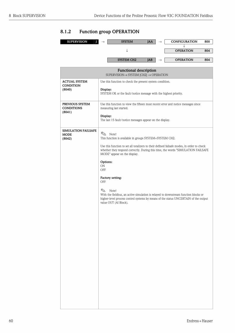
8 Block SUPERVISION Device Functions of the Proline Prosonic Flow 93C FOUNDATION Fieldbus
60 Endress+Hauser
8.1.2 Function group OPERATION
SUPERVISION J → SYSTEM JAA → CONFIGURATION 800
↓
↓ OPERATION 804
SYSTEM CH2 JAB → OPERATION 804
Functional descriptionSUPERVISION→ SYSTEM [CH2] → OPERATION
ACTUAL SYSTEM
CONDITION
(8040)
Use this function to check the present system condition.
Display:
SYSTEM OK or the fault/notice message with the highest priority.
PREVIOUS SYSTEM
CONDITIONS
(8041)
Use this function to view the fifteen most recent error and notice messages since
measuring last started.
Display:
The last 15 fault/notice messages appear on the display.
SIMULATION FAILSAFE
MODE
(8042)
! Note!
This function is available in groups SYSTEM+SYSTEM CH2.
Use this function to set all totalizers to their defined failsafe modes, in order to check
whether they respond correctly. During this time, the words "SIMULATION FAILSAFE
MODE" appear on the display.
Options:
ON
OFF
Factory setting:
OFF
! Note!
With the fieldbus, an active simulation is relayed to downstream function blocks or
higher-level process control systems by means of the status UNCERTAIN of the output
value OUT (AI Block).

Device Functions of the Proline Prosonic Flow 93C FOUNDATION Fieldbus 8 Block SUPERVISION
Endress+Hauser 61
SIMULATION
MEASURAND
(8043)
! Note!
This function is available in groups SYSTEM+SYSTEM CH2.
Use this function to set all totalizers to their defined flow-response modes, in order to
check whether they respond correctly. During this time, the words "SIMULATION
MEASURAND" appear on the display.
Options:
OFF
VOLUME FLOW (CH1 to CH2)
SOUND VELOCITY (CH1 to CH2)
Factory setting:
OFF
" Caution!
� The measuring device cannot be used for measuring while this simulation is in
progress.
� The setting is not saved in the event of a power failure.
! Note!
� An active simulation of the measurand is communicated to the subsequent function
blocks via the status “UNCERTAIN” for the process variables.
� The simulation is independent of the position of the jumper for the simulation mode on
the I/O board.
VALUE SIMULATION
MEASURAND
(8044)
! Note!
This function is available in groups SYSTEM+SYSTEM CH2.
! Note!
The function is not visible unless the function SIMULATION MEASURAND (8043) is
active.
Use this function to specify a selectable value (e.g. 12 m3/s). This is used to test the
associated functions in the device itself and downstream FOUNDATION Fieldbus
function blocks.
User input:
5-digit floating-point number, [unit]
Factory setting:
0 [unit]
" Caution!
� The setting is not saved in the event of a power failure.
� The appropriate unit is taken from the SYSTEM UNITS (ACA) function group
→ Page 12.
Functional descriptionSUPERVISION→ SYSTEM [CH2] → OPERATION

8 Block SUPERVISION Device Functions of the Proline Prosonic Flow 93C FOUNDATION Fieldbus
62 Endress+Hauser
SYSTEM RESET
(8046)
Use this function to perform a reset of the measuring system.
Options:
NO
RESTART SYSTEM (restart without interrupting power supply)
MEASURING TUBE DATA (restore the original calibration data)
! Note!
The T-DAT must be present in order to successfully restore the original calibration data
when the MEASURING TUBE DATA option is selected. If it is not, the error message K-
CAL T-DAT (# 043) appears on the display. For more information, please refer to the
Operating Instructions for Proline Prosonic Flow 93C FOUNDATION Fieldbus,
BA00145D.
Factory setting:
NO
TROUBLESHOOTING
(8047)
This function allows you to remedy errors that occur in the EEPROM. The EEPROM is
divided into various blocks. Only blocks in which an error has occurred are displayed.
Troubleshooting takes place by selecting the respective block and acknowledging using
the F key.
" Caution!
When troubleshooting a block, the parameters of the selected block are reset to the values
according to the factory setting.
Options:
CANCEL
"Faulty block"
OPERATION HOURS
(8048)
The hours of operation of the device appear on the display.
Display:
Depends on the number of hours of operation elapsed:
Hours of operation < 10 hours → display format = 00:00:00 (hr:min:sec)
Hours of operation 10 to 10,000 hours → display format = 0000:00 (hr:min)
Hours of operation > 10,000 hours → display format = 000000 (hr)
Functional descriptionSUPERVISION→ SYSTEM [CH2] → OPERATION

Device Functions of the Proline Prosonic Flow 93C FOUNDATION Fieldbus 8 Block SUPERVISION
Endress+Hauser 63
8.2 Group VERSION INFO
8.2.1 Function group DEVICE
8.2.2 Function group SENSOR
8.2.3 Function group AMPLIFIER
SUPERVISION J → SYSTEM JAA
↓
VERSION INFO JCA → DEVICE 810
Functional descriptionSUPERVISION → VERSION INFO → DEVICE
DEVICE SOFTWARE
(8100)
Displays the current device software version.
SUPERVISION J → SYSTEM JAA
↓
VERSION INFO JCA → DEVICE 810
↓
SENSOR 820
Functional descriptionSUPERVISION → VERSION INFO → SENSOR
SERIAL NUMBER
(8200)
Use this function to view the serial number of the sensor.
SUPERVISION J → SYSTEM JAA
↓
VERSION INFO JCA → DEVICE 810
↓
SENSOR 820
↓
AMPLIFIER 822
Functional descriptionSUPERVISION → VERSION INFO → AMPLIFIER
SOFTWARE REVISION
NUMBER AMPLIFIER
(8222)
Use this function to view the software revision number of the amplifier.
SOFTWARE
REVISION NUMBER
T-DAT
(8225)
Use this function to view the software revision number of the software used to create the
content of the T-DAT.

8 Block SUPERVISION Device Functions of the Proline Prosonic Flow 93C FOUNDATION Fieldbus
64 Endress+Hauser
8.2.4 Function group F-CHIP
8.2.5 Function group I/O MODULE
LANGUAGE GROUP
(8226)
Use this function to view the language group.
The following language groups can be ordered:
WEST EU / USA, EAST EU / SCAND., ASIA, CHINESE.
Display:
available language group
! Note!
� The language options of the available language group are displayed in the LANGUAGE
function (2000).
� You can change the language group via the configuration software FieldCare.
Please do not hesitate to contact your Endress+Hauser sales office if you have any
questions.
SUPERVISION J → SYSTEM JAA
↓
VERSION INFO JCA → DEVICE 810
↓
SENSOR 820
↓
AMPLIFIER 822
↓
F-CHIP 824
Functional descriptionSUPERVISION→ VERSION INFO → F-CHIP
STATUS F-CHIP
(8240)
Use this function to check whether an F-CHIP is installed.
SUPERVISION J → SYSTEM JAA
↓
VERSION INFO JCA → DEVICE 810
↓
SENSOR 820
↓
AMPLIFIER 822
↓
F-CHIP 824
↓
I/O MODULE 830
Functional descriptionSUPERVISION → VERSION INFO → I/O-MODUL
I/O MODULE TYPE
(8300)
Use this function to view the configuration of the I/O module complete with terminal
numbers.
SOFTWARE
REVISION NUMBER
I/O MODULE
(8303)
Use this function to view the software revision number of the I/O module.
Functional descriptionSUPERVISION → VERSION INFO → AMPLIFIER

Device Functions of the Proline Prosonic Flow 93C FOUNDATION Fieldbus 9 Factory settings
Endress+Hauser 65
9 Factory settings
9.1 SI units
9.1.1 Low flow cutoff, totalizer
9.1.2 Language
9.1.3 Length, temperature
Nominal diameter Low flow cut off Totalizer
(approx. v = 0.04 m/s)
[mm] [inch] Volume Vol.
300 12" 10 m3/h m3
350 14" 15 m3/h m3
400 16" 20 m3/h m3
450 18" 20 m3/h m3
500 20" 30 m3/h m3
600 24" 40 m3/h m3
700 28" 55 m3/h m3
– 30" 65 m3/h m3
800 32" 75 m3/h m3
900 36" 90 m3/h m3
1000 40" 115 m3/h m3
– 42" 125 m3/h m3
1200 48" 160 m3/h m3
– 54" 205 m3/h m3
1400 – 220 m3/h m3
– 60" 255 m3/h m3
1600 – 285 m3/h m3
– 66" 305 m3/h m3
1800 72" 360 m3/h m3
– 78" 450 m3/h m3
2000 – 450 m3/h m3
Country Language Country Language
Australia English Japan Japanese
Belgium Francais Malaysia English
Canada English Norway Norsk
Denmark Dansk Austria Deutsch
Germany Deutsch Sweden Svenska
England English Switzerland Deutsch
Finland Suomi Singapore English
France Francais Spain Espanol
Netherlands Nederlands South Africa English
Hong Kong English Thailand English
India English Hungary English
Instruments International English USA English
Italy Italiano
Unit
Length mm
Temperature °C

9 Factory settings Device Functions of the Proline Prosonic Flow 93C FOUNDATION Fieldbus
66 Endress+Hauser
9.2 US units (for USA and Canada only)
9.2.1 Low flow cutoff, totalizer
9.2.2 Language, length, temperature
Nominal diameter Low flow cut off Totalizer
(approx. v = 0.04 m/s)
[inch] [mm] Volume Vol.
12" 300 45 gal/min gal
14" 350 65 gal/min gal
16" 400 90 gal/min gal
18" 450 90 gal/min gal
20" 500 130 gal/min gal
24" 600 175 gal/min gal
28" 700 240 gal/min gal
30" – 275 gal/min gal
32" 800 325 gal/min gal
36" 900 400 gal/min gal
40" 1000 500 gal/min gal
42" – 550 gal/min gal
48" 1200 700 gal/min gal
54" – 1.3 Mgal/d Mgal
– 1400 1.4 Mgal/d Mgal
60" – 1.6 Mgal/d Mgal
– 1600 1.8 Mgal/d Mgal
66" – 1.9 Mgal/d Mgal
72" 1800 2.3 Mgal/d Mgal
78" – 2.9 Mgal/d Mgal
– 2000 2.9 Mgal/d Mgal
Unit
Language English
Length mm
Temperature °C

Device Functions of the Proline Prosonic Flow 93C FOUNDATION Fieldbus 10 Index Function matrix
Endress+Hauser 67
10 Index Function matrix
BlocksA = MEASURED VARIABLES . . . . . . . . . . . . . . . . . . . . . . . 9
B = QUICK SETUP . . . . . . . . . . . . . . . . . . . . . . . . . . . . . 16
C = USER INTERFACE . . . . . . . . . . . . . . . . . . . . . . . . . . 19
D = TOTALIZER . . . . . . . . . . . . . . . . . . . . . . . . . . . . . . . 35
G = BASIC FUNCTION . . . . . . . . . . . . . . . . . . . . . . . . . . 40
J = SUPERVISION . . . . . . . . . . . . . . . . . . . . . . . . . . . . . . 58
GroupsAAA = MEASURING VALUES . . . . . . . . . . . . . . . . . . . . . 10
ACA = SYSTEM UNITS . . . . . . . . . . . . . . . . . . . . . . . . . . 12
CAA = CONTROL . . . . . . . . . . . . . . . . . . . . . . . . . . . . . . 20
CCA = MAIN LINE . . . . . . . . . . . . . . . . . . . . . . . . . . . . . 24
CEA = ADDITIONAL LINE . . . . . . . . . . . . . . . . . . . . . . . 27
CGA = INFORMATION LINE . . . . . . . . . . . . . . . . . . . . . 31
DAA = TOTALIZER 1 . . . . . . . . . . . . . . . . . . . . . . . . . . . 36
DAB = TOTALIZER 2 . . . . . . . . . . . . . . . . . . . . . . . . . . . . 36
DAC = TOTALIZER 3 . . . . . . . . . . . . . . . . . . . . . . . . . . . 36
DJA = HANDLING TOTALIZER . . . . . . . . . . . . . . . . . . . . 39
GGA = FOUNDATION FIELDBUS . . . . . . . . . . . . . . . . . . 41
GIA, GIB = PROCESS PARAMETER (CH1 to CH2) . . . . . 44
GLA, GLB = SYSTEM PARAMETER (CH1...CH2) . . . . . . 50
GNA, GNB = SENSOR DATA (CH1...CH2) . . . . . . . . . . . 52
JAA = SYSTEM . . . . . . . . . . . . . . . . . . . . . . . . . . . . . . . . 59
JAB = SYSTEM CH2 . . . . . . . . . . . . . . . . . . . . . . . . . . . . 60
JCA = VERSION INFO . . . . . . . . . . . . . . . . . . . . . . . . . . . 63
Function groups000 = MAIN VALUES CH1 . . . . . . . . . . . . . . . . . . . . . . . 10
006 = MAIN VALUES CH2 . . . . . . . . . . . . . . . . . . . . . . . 10
008 = CALCULATED MAIN VALUES . . . . . . . . . . . . . . . 11
040 = CONFIGURATION . . . . . . . . . . . . . . . . . . . . . . . . 12
042 = ADDITIONAL CONFIGURATION . . . . . . . . . . . . . 14
200 = BASIC CONFIGURATION . . . . . . . . . . . . . . . . . . . 20
202 = UNLOCKING/LOCKING . . . . . . . . . . . . . . . . . . . . 22
204 = OPERATION . . . . . . . . . . . . . . . . . . . . . . . . . . . . . 23
220 = CONFIGURATION . . . . . . . . . . . . . . . . . . . . . . . . 24
222 = MULTIPLEX . . . . . . . . . . . . . . . . . . . . . . . . . . . . . 26
240 = CONFIGURATION . . . . . . . . . . . . . . . . . . . . . . . . 27
242 = MULTIPLEX . . . . . . . . . . . . . . . . . . . . . . . . . . . . . 29
260 = CONFIGURATION . . . . . . . . . . . . . . . . . . . . . . . . 31
262 = MULTIPLEX . . . . . . . . . . . . . . . . . . . . . . . . . . . . . 33
300 = CONFIGURATION . . . . . . . . . . . . . . . . . . . . . . . . 36
304 = OPERATION . . . . . . . . . . . . . . . . . . . . . . . . . . . . . 38
620 = CONFIGURATION . . . . . . . . . . . . . . . . . . . . . . . . 41
622 = FUNCTION BLOCKS . . . . . . . . . . . . . . . . . . . . . . . 42
624 = INFORMATION . . . . . . . . . . . . . . . . . . . . . . . . . . . 43
640 = CONFIGURATION . . . . . . . . . . . . . . . . . . . . . . . . 44
648 = ADJUSTMENT . . . . . . . . . . . . . . . . . . . . . . . . . . . . 46
654 = LIQUID DATA . . . . . . . . . . . . . . . . . . . . . . . . . . . . 47
660 = CONFIGURATION . . . . . . . . . . . . . . . . . . . . . . . . 50
680 = CONFIGURATION . . . . . . . . . . . . . . . . . . . . . . . . 52
681 = MEASURING TUBE . . . . . . . . . . . . . . . . . . . . . . . . 53
688 = SENSOR PARAMETER . . . . . . . . . . . . . . . . . . . . . . 54
689 = CALIBRATION DATA . . . . . . . . . . . . . . . . . . . . . . 56
691 = ORIG. FACT. CALIBRATION . . . . . . . . . . . . . . . . . 57
800 = CONFIGURATION . . . . . . . . . . . . . . . . . . . . . . . . 59
804 = OPERATION . . . . . . . . . . . . . . . . . . . . . . . . . . . . . 60
810 = DEVICE . . . . . . . . . . . . . . . . . . . . . . . . . . . . . . . . . 63
820 = SENSOR . . . . . . . . . . . . . . . . . . . . . . . . . . . . . . . . . 63
822 = AMPLIFIER . . . . . . . . . . . . . . . . . . . . . . . . . . . . . . 63
824 = F-CHIP . . . . . . . . . . . . . . . . . . . . . . . . . . . . . . . . . 64
830 = I/O MODULE . . . . . . . . . . . . . . . . . . . . . . . . . . . . 64

10 Index Function matrix Device Functions of the Proline Prosonic Flow 93C FOUNDATION Fieldbus
68 Endress+Hauser
Functions 0...0007 = SIGNAL STRENGTH CH1 . . . . . . . . . . . . . . . . . . . 10
0067 = SIGNAL STRENGTH CH2 . . . . . . . . . . . . . . . . . . . 10
0083 = AVERAGE VOLUME FLOW . . . . . . . . . . . . . . . . . 11
0086 = AVERAGE SOUND VELOCITY . . . . . . . . . . . . . . . 11
0087 = AVERAGE FLOW VELOCITY . . . . . . . . . . . . . . . . 11
0402 = UNIT VOLUME FLOW . . . . . . . . . . . . . . . . . . . . . 12
0403 = UNIT VOLUME . . . . . . . . . . . . . . . . . . . . . . . . . . 13
0422 = UNIT TEMPERATURE . . . . . . . . . . . . . . . . . . . . . 14
0423 = UNIT VISCOSITY . . . . . . . . . . . . . . . . . . . . . . . . . 14
0424 = UNIT LENGTH . . . . . . . . . . . . . . . . . . . . . . . . . . . 14
0425 = UNIT VELOCITY . . . . . . . . . . . . . . . . . . . . . . . . . 15
0429 = FORMAT DATE/TIME . . . . . . . . . . . . . . . . . . . . . 15
1...1002 = QUICK SETUP COMMISSIONING . . . . . . . . . . . . 16
1009 = T-DAT SAVE/LOAD . . . . . . . . . . . . . . . . . . . . . . . 16
2...2000 = LANGUAGE . . . . . . . . . . . . . . . . . . . . . . . . . . . . . 20
2002 = DISPLAY DAMPING . . . . . . . . . . . . . . . . . . . . . . . 20
2003 = CONTRAST LCD . . . . . . . . . . . . . . . . . . . . . . . . . 21
2004 = BACKLIGHT . . . . . . . . . . . . . . . . . . . . . . . . . . . . . 21
2009 = X-LINE CALCULATED MAIN VALUES . . . . . . . . . 21
2020 = ACCESS CODE . . . . . . . . . . . . . . . . . . . . . . . . . . . 22
2021 = DEFINE PRIVATE CODE . . . . . . . . . . . . . . . . . . . 22
2022 = STATUS ACCESS . . . . . . . . . . . . . . . . . . . . . . . . . 22
2023 = ACCESS CODE COUNTER . . . . . . . . . . . . . . . . . . 22
2040 = TEST DISPLAY . . . . . . . . . . . . . . . . . . . . . . . . . . . 23
2200 = ASSIGN . . . . . . . . . . . . . . . . . . . . . . . . . . . . . . . . 24
2201 = 100% VALUE . . . . . . . . . . . . . . . . . . . . . . . . . . . . 24
2202 = FORMAT . . . . . . . . . . . . . . . . . . . . . . . . . . . . . . . 25
2220 = ASSIGN . . . . . . . . . . . . . . . . . . . . . . . . . . . . . . . . 26
2221 = 100% VALUE . . . . . . . . . . . . . . . . . . . . . . . . . . . . 26
2222 = FORMAT . . . . . . . . . . . . . . . . . . . . . . . . . . . . . . . 26
2400 = ASSIGN . . . . . . . . . . . . . . . . . . . . . . . . . . . . . . . . 27
2401 = 100% VALUE . . . . . . . . . . . . . . . . . . . . . . . . . . . . 27
2402 = FORMAT . . . . . . . . . . . . . . . . . . . . . . . . . . . . . . . 28
2403 = DISPLAY MODE . . . . . . . . . . . . . . . . . . . . . . . . . . 28
2420 = ASSIGN . . . . . . . . . . . . . . . . . . . . . . . . . . . . . . . . 29
2421 = 100% VALUE . . . . . . . . . . . . . . . . . . . . . . . . . . . . 29
2422 = FORMAT . . . . . . . . . . . . . . . . . . . . . . . . . . . . . . . 30
2423 = DISPLAY MODE . . . . . . . . . . . . . . . . . . . . . . . . . . 30
2600 = ASSIGN . . . . . . . . . . . . . . . . . . . . . . . . . . . . . . . . 31
2601 = 100% VALUE . . . . . . . . . . . . . . . . . . . . . . . . . . . . 32
2602 = FORMAT . . . . . . . . . . . . . . . . . . . . . . . . . . . . . . . 32
2603 = DISPLAY MODE . . . . . . . . . . . . . . . . . . . . . . . . . . 32
2620 = ASSIGN . . . . . . . . . . . . . . . . . . . . . . . . . . . . . . . . 33
2621 = 100% VALUE . . . . . . . . . . . . . . . . . . . . . . . . . . . . 33
2622 = FORMAT . . . . . . . . . . . . . . . . . . . . . . . . . . . . . . . 34
2623 = DISPLAY MODE . . . . . . . . . . . . . . . . . . . . . . . . . . 34
3...3000 = ASSIGN . . . . . . . . . . . . . . . . . . . . . . . . . . . . . . . .36
3001 = UNIT TOTALIZER . . . . . . . . . . . . . . . . . . . . . . . . .37
3002 = TOTALIZER MODE . . . . . . . . . . . . . . . . . . . . . . .37
3003 = RESET TOTALIZER . . . . . . . . . . . . . . . . . . . . . . . .37
3040 = SUM . . . . . . . . . . . . . . . . . . . . . . . . . . . . . . . . . . .38
3041 = OVERFLOW . . . . . . . . . . . . . . . . . . . . . . . . . . . . .38
3800 = RESET ALL TOTALIZERS . . . . . . . . . . . . . . . . . . .39
3801 = FAILSAFE MODE . . . . . . . . . . . . . . . . . . . . . . . . .39
6...6200 = WRITE PROTECTION . . . . . . . . . . . . . . . . . . . . . .41
6201 = SIMULATION . . . . . . . . . . . . . . . . . . . . . . . . . . . .41
6203 = DEVICE PD-TAG . . . . . . . . . . . . . . . . . . . . . . . . .41
6220 = BLOCK SELECTION . . . . . . . . . . . . . . . . . . . . . . .42
6221 = OUT VALUE . . . . . . . . . . . . . . . . . . . . . . . . . . . . .42
6222 = IN VALUE . . . . . . . . . . . . . . . . . . . . . . . . . . . . . . .42
6223 = CASCADE IN VALUE . . . . . . . . . . . . . . . . . . . . . .42
6224 = SETPOINT VALUE . . . . . . . . . . . . . . . . . . . . . . . .42
6240 = MANUFACTURER ID . . . . . . . . . . . . . . . . . . . . . .43
6241 = DEVICE TYPE . . . . . . . . . . . . . . . . . . . . . . . . . . . .43
6242 = SERIAL NUMBER . . . . . . . . . . . . . . . . . . . . . . . . .43
6243 = DEVICE REVISION . . . . . . . . . . . . . . . . . . . . . . . .43
6244 = DD REVISION . . . . . . . . . . . . . . . . . . . . . . . . . . . .43
6400 = ASSIGN LOW FLOW CUT OFF . . . . . . . . . . . . . . .44
6402 = ON-VALUE LOW FLOW CUT OFF . . . . . . . . . . . .44
6403 = OFF-VALUE LOW FLOW CUT OFF . . . . . . . . . . .44
6404 = PRESSURE SHOCK SUPPRESSION . . . . . . . . . . . .45
6480 = ZEROPOINT ADJUSTMENT . . . . . . . . . . . . . . . . .46
6540 = LIQUID . . . . . . . . . . . . . . . . . . . . . . . . . . . . . . . . .47
6541 = TEMPERATURE . . . . . . . . . . . . . . . . . . . . . . . . . .47
6542 = SOUND VELOCITY LIQUID . . . . . . . . . . . . . . . . .48
6543 = VISCOSITY . . . . . . . . . . . . . . . . . . . . . . . . . . . . . .48
6545 = SOUND VELOCITY NEGATIVE . . . . . . . . . . . . . .48
6546 = SOUND VELOCITY POSITIVE . . . . . . . . . . . . . . .49
6600 = INSTALLATION DIRECTION SENSOR . . . . . . . . .50
6601 = MEASURING MODE . . . . . . . . . . . . . . . . . . . . . .50
6603 = FLOW DAMPING . . . . . . . . . . . . . . . . . . . . . . . . .50
6605 = POSITIVE ZERO RETURN . . . . . . . . . . . . . . . . . . .51
6800 = K-FACTOR . . . . . . . . . . . . . . . . . . . . . . . . . . . . . .52
6803 = ZERO POINT . . . . . . . . . . . . . . . . . . . . . . . . . . . .52
6806 = CO . . . . . . . . . . . . . . . . . . . . . . . . . . . . . . . . . . . .52
6808 = CALIBRATION DATE . . . . . . . . . . . . . . . . . . . . . .52
6810 = PIPE STANDARD . . . . . . . . . . . . . . . . . . . . . . . . .53
6811 = NOMINAL DIAMETER . . . . . . . . . . . . . . . . . . . . .53
6812 = PIPE DIAMETER . . . . . . . . . . . . . . . . . . . . . . . . . .53
6813 = WALL THICKNESS . . . . . . . . . . . . . . . . . . . . . . . .53
6880 = MEASUREMENT . . . . . . . . . . . . . . . . . . . . . . . . .54
6881 = SENSOR TYPE . . . . . . . . . . . . . . . . . . . . . . . . . . .54
6882 = SENSOR CONFIGURATION . . . . . . . . . . . . . . . . .54
6883 = CABLE LENGTH . . . . . . . . . . . . . . . . . . . . . . . . . .55
6890 = P-FACTOR . . . . . . . . . . . . . . . . . . . . . . . . . . . . . .56
6891 = ZERO POINT . . . . . . . . . . . . . . . . . . . . . . . . . . . .56
6893 = CORRECTION FACTOR . . . . . . . . . . . . . . . . . . . .56
6910 = CALIBRATION DATE . . . . . . . . . . . . . . . . . . . . . .57

Device Functions of the Proline Prosonic Flow 93C FOUNDATION Fieldbus 10 Index Function matrix
Endress+Hauser 69
8...8005 = ALARM DELAY . . . . . . . . . . . . . . . . . . . . . . . . . . 59
8007 = PERMANENT STORAGE . . . . . . . . . . . . . . . . . . . 59
8040 = ACTUAL SYSTEM CONDITION . . . . . . . . . . . . . 60
8041 = PREVIOUS SYSTEM CONDITIONS . . . . . . . . . . . 60
8042 = SIMULATION FAILSAFE MODE . . . . . . . . . . . . . 60
8043 = SIMULATION MEASURAND . . . . . . . . . . . . . . . . 61
8044 = VALUE SIMULATION MEASURAND . . . . . . . . . 61
8046 = SYSTEM RESET . . . . . . . . . . . . . . . . . . . . . . . . . . 62
8047 = TROUBLESHOOTING . . . . . . . . . . . . . . . . . . . . . 62
8048 = OPERATION HOURS . . . . . . . . . . . . . . . . . . . . . . 62
8100 = DEVICE SOFTWARE . . . . . . . . . . . . . . . . . . . . . . 63
8200 = SERIAL NUMBER . . . . . . . . . . . . . . . . . . . . . . . . 63
8222 = SOFTWARE REVISION NUMBER AMPLIFIER . . . 63
8225 = SOFTWARE REVISION NUMBER T-DAT . . . . . . 63
8226 = LANGUAGE GROUP . . . . . . . . . . . . . . . . . . . . . . 64
8240 = STATUS F-CHIP . . . . . . . . . . . . . . . . . . . . . . . . . 64
8300 = I/O MODULE TYPE . . . . . . . . . . . . . . . . . . . . . . 64
8303 = SOFTWARE REVISION NUMBER I/O MODULE . 64

Device Functions of the Proline Prosonic Flow 93C FOUNDATION Fieldbus 11 Index
Endress+Hauser 70
11 Index
AActual system condition . . . . . . . . . . . . . . . . . . . . . . . . . . 60
Additional configuration . . . . . . . . . . . . . . . . . . . . . . . . . . 14
Additional line
Configuration . . . . . . . . . . . . . . . . . . . . . . . . . . . . . . . 27
Multiplex . . . . . . . . . . . . . . . . . . . . . . . . . . . . . . . . . . 29
Adjustment
Function group . . . . . . . . . . . . . . . . . . . . . . . . . . . . . . 46
Zero point . . . . . . . . . . . . . . . . . . . . . . . . . . . . . . . . . . 46
Alarm delay . . . . . . . . . . . . . . . . . . . . . . . . . . . . . . . . . . . 59
Amplifier (version info) . . . . . . . . . . . . . . . . . . . . . . . . . . . 63
Assign
Additional line . . . . . . . . . . . . . . . . . . . . . . . . . . . . . . 27
Additional line (Multiplex) . . . . . . . . . . . . . . . . . . . . . 29
Information line . . . . . . . . . . . . . . . . . . . . . . . . . . . . . 31
Information line (Multiplex) . . . . . . . . . . . . . . . . . . . . 33
Low flow cut off . . . . . . . . . . . . . . . . . . . . . . . . . . . . . 44
Main line . . . . . . . . . . . . . . . . . . . . . . . . . . . . . . . . . . 24
Main line (Multiplex) . . . . . . . . . . . . . . . . . . . . . . . . . 26
Totalizer . . . . . . . . . . . . . . . . . . . . . . . . . . . . . . . . . . . 36
Available functions . . . . . . . . . . . . . . . . . . . . . . . . . . . . . . . 8
Average flow velocity . . . . . . . . . . . . . . . . . . . . . . . . . . . . 11
Average sound velocity . . . . . . . . . . . . . . . . . . . . . . . . . . . 11
Average volume flow . . . . . . . . . . . . . . . . . . . . . . . . . . . . 11
BBasic configuration (user interface) . . . . . . . . . . . . . . . . . . 20
Basic function
FOUNDATION Fieldbus
Function blocks . . . . . . . . . . . . . . . . . . . . . . . . . 42
Information . . . . . . . . . . . . . . . . . . . . . . . . . . . . 43
Basic functions (Block) . . . . . . . . . . . . . . . . . . . . . . . . . . . 40
Block
Basic function . . . . . . . . . . . . . . . . . . . . . . . . . . . . . . . 40
Display . . . . . . . . . . . . . . . . . . . . . . . . . . . . . . . . . . . . 19
Measured variables . . . . . . . . . . . . . . . . . . . . . . . . . . . . 9
Quick Setup . . . . . . . . . . . . . . . . . . . . . . . . . . . . . . . . 16
Supervision . . . . . . . . . . . . . . . . . . . . . . . . . . . . . . . . . 58
Totalizer . . . . . . . . . . . . . . . . . . . . . . . . . . . . . . . . . . . 35
Block Selection . . . . . . . . . . . . . . . . . . . . . . . . . . . . . . . . . 42
CCable length . . . . . . . . . . . . . . . . . . . . . . . . . . . . . . . . . . . 55
Calculated main values (displaying) . . . . . . . . . . . . . . . . . 21
Calibration
Factory calibration . . . . . . . . . . . . . . . . . . . . . . . . . . . 57
Calibration data
Correction factor . . . . . . . . . . . . . . . . . . . . . . . . . . . . . 56
P-factor . . . . . . . . . . . . . . . . . . . . . . . . . . . . . . . . . . . 56
Sensor data . . . . . . . . . . . . . . . . . . . . . . . . . . . . . . 54, 56
Zero point . . . . . . . . . . . . . . . . . . . . . . . . . . . . . . . . . . 56
Calibration date . . . . . . . . . . . . . . . . . . . . . . . . . . . . . 52, 57
Cascade IN Value . . . . . . . . . . . . . . . . . . . . . . . . . . . . . . . 42
Code
Access . . . . . . . . . . . . . . . . . . . . . . . . . . . . . . . . . . . . . 22
Access counter . . . . . . . . . . . . . . . . . . . . . . . . . . . . . . 22
Customer . . . . . . . . . . . . . . . . . . . . . . . . . . . . . . . . . . 22
Configuration
Additional line . . . . . . . . . . . . . . . . . . . . . . . . . . . . . . 27
FOUNDATION Fieldbus . . . . . . . . . . . . . . . . . . . . . . . 41
Information line . . . . . . . . . . . . . . . . . . . . . . . . . . . . . 31
Main line . . . . . . . . . . . . . . . . . . . . . . . . . . . . . . . . . . 24
Process parameter . . . . . . . . . . . . . . . . . . . . . . . . . . . . 44
Sensor data (CH1...CH2) . . . . . . . . . . . . . . . . . . . . . . . 52
System . . . . . . . . . . . . . . . . . . . . . . . . . . . . . . . . . . . . 59
System parameter (CH1...CH2) . . . . . . . . . . . . . . . . . . 50
System units . . . . . . . . . . . . . . . . . . . . . . . . . . . . . . . . 12
Totalizer . . . . . . . . . . . . . . . . . . . . . . . . . . . . . . . . . . . 36
Contrast LCD . . . . . . . . . . . . . . . . . . . . . . . . . . . . . . . . . . 21
Control
Operation . . . . . . . . . . . . . . . . . . . . . . . . . . . . . . . . . . 23
Unlocking/locking . . . . . . . . . . . . . . . . . . . . . . . . . . . 22
Control (group CAA)
Basic configuration . . . . . . . . . . . . . . . . . . . . . . . . . . . 20
Correction factor . . . . . . . . . . . . . . . . . . . . . . . . . . . . . . . 56
C0 . . . . . . . . . . . . . . . . . . . . . . . . . . . . . . . . . . . . . . . . . . 52
DDamping
Display . . . . . . . . . . . . . . . . . . . . . . . . . . . . . . . . . . . . 20
Flow . . . . . . . . . . . . . . . . . . . . . . . . . . . . . . . . . . . . . . 50
DD Revision . . . . . . . . . . . . . . . . . . . . . . . . . . . . . . . . . . . 43
Define private code . . . . . . . . . . . . . . . . . . . . . . . . . . . . . . 22
Device PD-Tag . . . . . . . . . . . . . . . . . . . . . . . . . . . . . . . . . 41
Device revision . . . . . . . . . . . . . . . . . . . . . . . . . . . . . . . . . 43
Device software . . . . . . . . . . . . . . . . . . . . . . . . . . . . . . . . 63
Device type . . . . . . . . . . . . . . . . . . . . . . . . . . . . . . . . . . . 43
Device (version info) . . . . . . . . . . . . . . . . . . . . . . . . . . . . . 63
Display
Calculated main values . . . . . . . . . . . . . . . . . . . . . . . . 21
Damping . . . . . . . . . . . . . . . . . . . . . . . . . . . . . . . . . . . 20
Language selection . . . . . . . . . . . . . . . . . . . . . . . . . . . 20
Lighting (back lighting) . . . . . . . . . . . . . . . . . . . . . . . . 21
See Display
Test . . . . . . . . . . . . . . . . . . . . . . . . . . . . . . . . . . . . . . 23
User interface (Block C) . . . . . . . . . . . . . . . . . . . . . . . 19
Display lines of local operation . . . . . . . . . . . . . . . . . . . . . . 8
Display mode
Additional line . . . . . . . . . . . . . . . . . . . . . . . . . . . . . . 28
Additional line (Multiplex) . . . . . . . . . . . . . . . . . . . . . 30
Information line . . . . . . . . . . . . . . . . . . . . . . . . . . . . . 32
Information line (Multiplex) . . . . . . . . . . . . . . . . . . . . 34
FFactory calibration . . . . . . . . . . . . . . . . . . . . . . . . . . . . . . 57
Factory settings . . . . . . . . . . . . . . . . . . . . . . . . . . . . . . . . . 65
Failsafe mode
All totalizers . . . . . . . . . . . . . . . . . . . . . . . . . . . . . . . . 39
F-CHIP (version info) . . . . . . . . . . . . . . . . . . . . . . . . . . . . 64

11 Index Device Functions of the Proline Prosonic Flow 93C FOUNDATION Fieldbus
71 Endress+Hauser
Flow damping . . . . . . . . . . . . . . . . . . . . . . . . . . . . . . . . . . 50
Flow velocity
Average . . . . . . . . . . . . . . . . . . . . . . . . . . . . . . . . . . . . 11
Format
Additional line . . . . . . . . . . . . . . . . . . . . . . . . . . . . . . . 28
Additional line (Multiplex) . . . . . . . . . . . . . . . . . . . . . . 30
Date/Time . . . . . . . . . . . . . . . . . . . . . . . . . . . . . . . . . 15
Information line . . . . . . . . . . . . . . . . . . . . . . . . . . . . . . 32
Information line (Multiplex) . . . . . . . . . . . . . . . . . . . . . 34
Main line . . . . . . . . . . . . . . . . . . . . . . . . . . . . . . . . . . . 25
Main line (Multiplex) . . . . . . . . . . . . . . . . . . . . . . . . . . 26
FOUNDATION Fieldbus
Configuration . . . . . . . . . . . . . . . . . . . . . . . . . . . . . . . . 41
Function blocks . . . . . . . . . . . . . . . . . . . . . . . . . . . . . . 42
Information . . . . . . . . . . . . . . . . . . . . . . . . . . . . . . . . . 43
Function group
Additional configuration . . . . . . . . . . . . . . . . . . . . . . . . 14
Adjustment . . . . . . . . . . . . . . . . . . . . . . . . . . . . . . . . . 46
Amplifier . . . . . . . . . . . . . . . . . . . . . . . . . . . . . . . . . . . 63
Basic configuration (user interface) . . . . . . . . . . . . . . . . 20
Calculated main values . . . . . . . . . . . . . . . . . . . . . . . . 11
Configuration
Additional line . . . . . . . . . . . . . . . . . . . . . . . . . . . 27
Calibration data . . . . . . . . . . . . . . . . . . . . . . . 54, 56
FOUNDATION Fieldbus . . . . . . . . . . . . . . . . . . . 41
Information line . . . . . . . . . . . . . . . . . . . . . . . . . . 31
Main line . . . . . . . . . . . . . . . . . . . . . . . . . . . . . . 24
Process parameter . . . . . . . . . . . . . . . . . . . . . . . . 44
Sensor data (CH1...CH2) . . . . . . . . . . . . . . . . . . . 52
Sensor parameter . . . . . . . . . . . . . . . . . . . . . . . . . 54
System . . . . . . . . . . . . . . . . . . . . . . . . . . . . . . . . 59
System parameter (CH1...CH2) . . . . . . . . . . . . . . 50
System units . . . . . . . . . . . . . . . . . . . . . . . . . . . . 12
Totalizer . . . . . . . . . . . . . . . . . . . . . . . . . . . . . . . 36
F-CHIP . . . . . . . . . . . . . . . . . . . . . . . . . . . . . . . . . . . . 64
Function blocks (FOUNDATION Fieldbus) . . . . . . . . . . 42
Information (FOUNDATION Fieldbus) . . . . . . . . . . . . . 43
I/O Module . . . . . . . . . . . . . . . . . . . . . . . . . . . . . . . . . 64
Liquid data . . . . . . . . . . . . . . . . . . . . . . . . . . . . . . . . . 47
Main values . . . . . . . . . . . . . . . . . . . . . . . . . . . . . . . . . 10
Measuring values
Main values CH2 . . . . . . . . . . . . . . . . . . . . . . . . 10
Multiplex
Additional line . . . . . . . . . . . . . . . . . . . . . . . . . . . 29
Information line . . . . . . . . . . . . . . . . . . . . . . . . . . 33
Main line . . . . . . . . . . . . . . . . . . . . . . . . . . . . . . 26
Operation
Display . . . . . . . . . . . . . . . . . . . . . . . . . . . . . . . . 23
System . . . . . . . . . . . . . . . . . . . . . . . . . . . . . . . . 60
Totalizer . . . . . . . . . . . . . . . . . . . . . . . . . . . . . . . 38
Original factory calibration . . . . . . . . . . . . . . . . . . . . . . 57
Pipe data . . . . . . . . . . . . . . . . . . . . . . . . . . . . . . . . . . . 53
Sensor . . . . . . . . . . . . . . . . . . . . . . . . . . . . . . . . . . . . . 63
Unlocking/locking (user interface) . . . . . . . . . . . . . . . . 22
Function matrix
General layout . . . . . . . . . . . . . . . . . . . . . . . . . . . . . . . . 6
Identification code . . . . . . . . . . . . . . . . . . . . . . . . . . . . . 7
Overview . . . . . . . . . . . . . . . . . . . . . . . . . . . . . . . . . . . . 8
GGroup
Additional line . . . . . . . . . . . . . . . . . . . . . . . . . . . . . . .27
Control (User interface) . . . . . . . . . . . . . . . . . . . . . . . .20
FOUNDATION Fieldbus . . . . . . . . . . . . . . . . . . . . . . . .41
Handling Totalizer . . . . . . . . . . . . . . . . . . . . . . . . . . . .39
Information line . . . . . . . . . . . . . . . . . . . . . . . . . . . . . .31
Main line . . . . . . . . . . . . . . . . . . . . . . . . . . . . . . . . . . .24
Measuring values . . . . . . . . . . . . . . . . . . . . . . . . . . . . .10
PROCESS PARAMETER (CH1 to CH2) . . . . . . . . . . . . .44
Sensor data (CH1...CH2) . . . . . . . . . . . . . . . . . . . . . . .52
System . . . . . . . . . . . . . . . . . . . . . . . . . . . . . . . . . . . . .59
System parameter (CH1...CH2) . . . . . . . . . . . . . . . . . .50
System units . . . . . . . . . . . . . . . . . . . . . . . . . . . . . . . . .12
Totalizer (1 to 3) . . . . . . . . . . . . . . . . . . . . . . . . . . . . .36
Version info . . . . . . . . . . . . . . . . . . . . . . . . . . . . . . . . .63
HHandling Totalizer . . . . . . . . . . . . . . . . . . . . . . . . . . . . . . .39
IIllustration of function description . . . . . . . . . . . . . . . . . . . .7
IN Value . . . . . . . . . . . . . . . . . . . . . . . . . . . . . . . . . . . . . .42
Information line
Configuration . . . . . . . . . . . . . . . . . . . . . . . . . . . . . . . .31
Multiplex . . . . . . . . . . . . . . . . . . . . . . . . . . . . . . . . . . .33
Information (FOUNDATION Fieldbus) . . . . . . . . . . . . . . . .43
Installation direction sensor . . . . . . . . . . . . . . . . . . . . . . . .50
I/O Module . . . . . . . . . . . . . . . . . . . . . . . . . . . . . . . . . . . .64
KK-Factor . . . . . . . . . . . . . . . . . . . . . . . . . . . . . . . . . . . . . .52
LLanguage
Factory settings (country) . . . . . . . . . . . . . . . . . . . . . . .65
Language group (display) . . . . . . . . . . . . . . . . . . . . . . .64
Options
. . . . . . . . . . . . . . . . . . . . . . . . . . . . . . . . . . . . . .20
Liquid data (function group) . . . . . . . . . . . . . . . . . . . . . . . .47
Local operation (display lines) . . . . . . . . . . . . . . . . . . . . . . .8
Low flow cut off
Assign . . . . . . . . . . . . . . . . . . . . . . . . . . . . . . . . . . . . .44
Off-value . . . . . . . . . . . . . . . . . . . . . . . . . . . . . . . . . . .44
On-value . . . . . . . . . . . . . . . . . . . . . . . . . . . . . . . . . . .44
MMain line
Configuration . . . . . . . . . . . . . . . . . . . . . . . . . . . . . . . .24
Multiplex . . . . . . . . . . . . . . . . . . . . . . . . . . . . . . . . . . .26
Main values . . . . . . . . . . . . . . . . . . . . . . . . . . . . . . . . . . . .10
Manufacturer ID . . . . . . . . . . . . . . . . . . . . . . . . . . . . . . . .43
Measured variables (block A) . . . . . . . . . . . . . . . . . . . . . . . .9
Measurement . . . . . . . . . . . . . . . . . . . . . . . . . . . . . . . . . .54
Measuring mode . . . . . . . . . . . . . . . . . . . . . . . . . . . . . . . .50
Measuring tube
Diameter . . . . . . . . . . . . . . . . . . . . . . . . . . . . . . . . . . .53
Nominal diameter . . . . . . . . . . . . . . . . . . . . . . . . . . . .53
Pipe standard . . . . . . . . . . . . . . . . . . . . . . . . . . . . . . . .53
Wall thickness . . . . . . . . . . . . . . . . . . . . . . . . . . . . . . .53

Device Functions of the Proline Prosonic Flow 93C FOUNDATION Fieldbus 11 Index
Endress+Hauser 72
Measuring values . . . . . . . . . . . . . . . . . . . . . . . . . . . . . . . 10
Calculated main values . . . . . . . . . . . . . . . . . . . . . . . . 11
Main values . . . . . . . . . . . . . . . . . . . . . . . . . . . . . . . . 10
Main values CH2 . . . . . . . . . . . . . . . . . . . . . . . . . . . . 10
Multiplex
Additional line . . . . . . . . . . . . . . . . . . . . . . . . . . . . . . 29
Information line . . . . . . . . . . . . . . . . . . . . . . . . . . . . . 33
Main line . . . . . . . . . . . . . . . . . . . . . . . . . . . . . . . . . . 26
NNominal diameter . . . . . . . . . . . . . . . . . . . . . . . . . . . . . . 53
OOff-value, low-flow cutoff . . . . . . . . . . . . . . . . . . . . . . . . . 44
On-value, low-flow cutoff . . . . . . . . . . . . . . . . . . . . . . . . . 44
Operation
Display . . . . . . . . . . . . . . . . . . . . . . . . . . . . . . . . . . . . 23
System . . . . . . . . . . . . . . . . . . . . . . . . . . . . . . . . . . . . 60
Totalizer . . . . . . . . . . . . . . . . . . . . . . . . . . . . . . . . . . . 38
Operation hours . . . . . . . . . . . . . . . . . . . . . . . . . . . . . . . . 62
OUT Value . . . . . . . . . . . . . . . . . . . . . . . . . . . . . . . . . . . . 42
Overflow
Totalizer . . . . . . . . . . . . . . . . . . . . . . . . . . . . . . . . . . . 38
PPermanent storage . . . . . . . . . . . . . . . . . . . . . . . . . . . . . . 59
P-factor . . . . . . . . . . . . . . . . . . . . . . . . . . . . . . . . . . . . . . 56
Pipe data . . . . . . . . . . . . . . . . . . . . . . . . . . . . . . . . . . . . . 53
Pipe diameter . . . . . . . . . . . . . . . . . . . . . . . . . . . . . . . . . . 53
Pipe standard . . . . . . . . . . . . . . . . . . . . . . . . . . . . . . . . . . 53
Positive zero return . . . . . . . . . . . . . . . . . . . . . . . . . . . . . 51
Pressure shock suppression . . . . . . . . . . . . . . . . . . . . . . . . 45
Previous system conditions . . . . . . . . . . . . . . . . . . . . . . . . 60
Process parameter Configuration . . . . . . . . . . . . . . . . . . . 44
Process parameter (CH1...CH2), (Group GIA, GIB)
Adjustment . . . . . . . . . . . . . . . . . . . . . . . . . . . . . . . . . 46
Liquid . . . . . . . . . . . . . . . . . . . . . . . . . . . . . . . . . . . . . 47
Liquid data . . . . . . . . . . . . . . . . . . . . . . . . . . . . . . . . . 47
Pipe data . . . . . . . . . . . . . . . . . . . . . . . . . . . . . . . . . . 53
Temperature . . . . . . . . . . . . . . . . . . . . . . . . . . . . . . . . 47
QQuick Setup (Block B)
Commission . . . . . . . . . . . . . . . . . . . . . . . . . . . . . . . . 16
Overview . . . . . . . . . . . . . . . . . . . . . . . . . . . . . . . . . . 16
RReset
All totalizers . . . . . . . . . . . . . . . . . . . . . . . . . . . . . . . . 39
System . . . . . . . . . . . . . . . . . . . . . . . . . . . . . . . . . . . . 62
Totalizer . . . . . . . . . . . . . . . . . . . . . . . . . . . . . . . . . . . 37
SSensor Type . . . . . . . . . . . . . . . . . . . . . . . . . . . . . . . . . . . 54
Sensor data (group GNA, GNB)
Configuration . . . . . . . . . . . . . . . . . . . . . . . . . . . . . . . 52
Original factory calibration . . . . . . . . . . . . . . . . . . . . . 57
Sensor settings . . . . . . . . . . . . . . . . . . . . . . . . . . . . . . 54
Sensor type . . . . . . . . . . . . . . . . . . . . . . . . . . . . . . . . . 54
Sensor parameter . . . . . . . . . . . . . . . . . . . . . . . . . . . . . . . 54
Sensor settings . . . . . . . . . . . . . . . . . . . . . . . . . . . . . . . . . 54
Sensor (version info) . . . . . . . . . . . . . . . . . . . . . . . . . . . . . 63
Serial number . . . . . . . . . . . . . . . . . . . . . . . . . . . . . . . . . . 43
Serial number sensor . . . . . . . . . . . . . . . . . . . . . . . . . . . . 63
Setpoint value . . . . . . . . . . . . . . . . . . . . . . . . . . . . . . . . . . 42
Signal strength
Channel 1 . . . . . . . . . . . . . . . . . . . . . . . . . . . . . . . . . . 10
Channel 2 . . . . . . . . . . . . . . . . . . . . . . . . . . . . . . . . . . 10
Simulation . . . . . . . . . . . . . . . . . . . . . . . . . . . . . . . . . . . . 41
Failsafe mode . . . . . . . . . . . . . . . . . . . . . . . . . . . . . . . 60
Measured variable . . . . . . . . . . . . . . . . . . . . . . . . . . . . 61
Value measured variable . . . . . . . . . . . . . . . . . . . . . . . 61
Software revision number
Amplifier . . . . . . . . . . . . . . . . . . . . . . . . . . . . . . . . . . . 63
I/O Module . . . . . . . . . . . . . . . . . . . . . . . . . . . . . . . . 64
T-DAT . . . . . . . . . . . . . . . . . . . . . . . . . . . . . . . . . . . . 63
Sound velocity
Average . . . . . . . . . . . . . . . . . . . . . . . . . . . . . . . . . . . 11
Liquid . . . . . . . . . . . . . . . . . . . . . . . . . . . . . . . . . . . . . 48
Negative . . . . . . . . . . . . . . . . . . . . . . . . . . . . . . . . . . . 48
Positive . . . . . . . . . . . . . . . . . . . . . . . . . . . . . . . . . . . . 49
Status access . . . . . . . . . . . . . . . . . . . . . . . . . . . . . . . . . . . 22
Status F-CHIP . . . . . . . . . . . . . . . . . . . . . . . . . . . . . . . . . . 64
Sum Totalizer . . . . . . . . . . . . . . . . . . . . . . . . . . . . . . . . . . 38
Supervision (Block J) . . . . . . . . . . . . . . . . . . . . . . . . . . . . . 58
System condition
Actual . . . . . . . . . . . . . . . . . . . . . . . . . . . . . . . . . . . . . 60
Previous . . . . . . . . . . . . . . . . . . . . . . . . . . . . . . . . . . . 60
System parameter (Group GLA, GLB)
Configuration . . . . . . . . . . . . . . . . . . . . . . . . . . . . . . . 50
System units
Additional configuration . . . . . . . . . . . . . . . . . . . . . . . 14
Configuration . . . . . . . . . . . . . . . . . . . . . . . . . . . . . . . 12
System (group JAA)
Configuration . . . . . . . . . . . . . . . . . . . . . . . . . . . . . . . 59
Operation . . . . . . . . . . . . . . . . . . . . . . . . . . . . . . . . . . 60
Reset . . . . . . . . . . . . . . . . . . . . . . . . . . . . . . . . . . . . . . 62
TT-DAT Save/Load . . . . . . . . . . . . . . . . . . . . . . . . . . . 16, 18
Temperature (liquid) . . . . . . . . . . . . . . . . . . . . . . . . . . . . . 47
Test display . . . . . . . . . . . . . . . . . . . . . . . . . . . . . . . . . . . 23
Totalizer
Assign . . . . . . . . . . . . . . . . . . . . . . . . . . . . . . . . . . . . . 36
Configuration . . . . . . . . . . . . . . . . . . . . . . . . . . . . . . . 36
Failsafe mode . . . . . . . . . . . . . . . . . . . . . . . . . . . . . . . 39
Handling Totalizer . . . . . . . . . . . . . . . . . . . . . . . . . . . . 39
Operation . . . . . . . . . . . . . . . . . . . . . . . . . . . . . . . . . . 38
Overflow . . . . . . . . . . . . . . . . . . . . . . . . . . . . . . . . . . 38
Reset . . . . . . . . . . . . . . . . . . . . . . . . . . . . . . . . . . . . . . 37
Sum . . . . . . . . . . . . . . . . . . . . . . . . . . . . . . . . . . . . . . 38
Totalizer Mode . . . . . . . . . . . . . . . . . . . . . . . . . . . . . . 37
Unit . . . . . . . . . . . . . . . . . . . . . . . . . . . . . . . . . . . . . . 37
Totalizer Mode . . . . . . . . . . . . . . . . . . . . . . . . . . . . . . . . . 37
Troubleshooting 62Type
Device . . . . . . . . . . . . . . . . . . . . . . . . . . . . . . . . . . . . 43
I/O Module . . . . . . . . . . . . . . . . . . . . . . . . . . . . . . . . 64
Sensor . . . . . . . . . . . . . . . . . . . . . . . . . . . . . . . . . . . . . 54

11 Index Device Functions of the Proline Prosonic Flow 93C FOUNDATION Fieldbus
73 Endress+Hauser
UUnit
Length . . . . . . . . . . . . . . . . . . . . . . . . . . . . . . . . . . . . . 14
Temperature . . . . . . . . . . . . . . . . . . . . . . . . . . . . . . . . 14
Totalizer . . . . . . . . . . . . . . . . . . . . . . . . . . . . . . . . . . . 37
Velocity . . . . . . . . . . . . . . . . . . . . . . . . . . . . . . . . . . . . 15
Viscosity . . . . . . . . . . . . . . . . . . . . . . . . . . . . . . . . . . . 14
Volume . . . . . . . . . . . . . . . . . . . . . . . . . . . . . . . . . . . . 13
Volume flow . . . . . . . . . . . . . . . . . . . . . . . . . . . . . . . . 12
Unlocking/locking (user interface) . . . . . . . . . . . . . . . . . . . 22
VValue simulation
Measured variable . . . . . . . . . . . . . . . . . . . . . . . . . . . . 61
Version-Info (group JCA)
Amplifier . . . . . . . . . . . . . . . . . . . . . . . . . . . . . . . . . . . 63
F-CHIP . . . . . . . . . . . . . . . . . . . . . . . . . . . . . . . . . . . . 64
I/O Module . . . . . . . . . . . . . . . . . . . . . . . . . . . . . . . . . 64
Sensor . . . . . . . . . . . . . . . . . . . . . . . . . . . . . . . . . . . . . 63
Viscosity . . . . . . . . . . . . . . . . . . . . . . . . . . . . . . . . . . . . . . 48
Volume flow
Average . . . . . . . . . . . . . . . . . . . . . . . . . . . . . . . . . . . . 11
Unit . . . . . . . . . . . . . . . . . . . . . . . . . . . . . . . . . . . . . . . 12
WWall thickness . . . . . . . . . . . . . . . . . . . . . . . . . . . . . . . . . . 53
Write protection . . . . . . . . . . . . . . . . . . . . . . . . . . . . . . . . 41
XXline calculated main values . . . . . . . . . . . . . . . . . . . . . . . 21
ZZero point . . . . . . . . . . . . . . . . . . . . . . . . . . . . . . . . . . 52, 56
Zero point adjustment . . . . . . . . . . . . . . . . . . . . . . . . . . . . 46
Numbers100% value flow
Additional line . . . . . . . . . . . . . . . . . . . . . . . . . . . . . . . 27
Additional line (Multiplex) . . . . . . . . . . . . . . . . . . . . . . 29
Information line . . . . . . . . . . . . . . . . . . . . . . . . . . . . . . 32
Information line (Multiplex) . . . . . . . . . . . . . . . . . . . . . 33
Main line . . . . . . . . . . . . . . . . . . . . . . . . . . . . . . . . . . . 24
Main line (Multiplex) . . . . . . . . . . . . . . . . . . . . . . . . . . 26

11 Index Device Functions of the Proline Prosonic Flow 93C FOUNDATION Fieldbus
74 Endress+Hauser

Device Functions of the Proline Prosonic Flow 93C FOUNDATION Fieldbus Content FOUNDATION Fieldbus
Endress+Hauser 75
Content FOUNDATION Fieldbus
1 Operation via FOUNDATION Fieldbus . . . . . . . . . . . . . . . . . . . . 77
1.1 Block model. . . . . . . . . . . . . . . . . . . . . . . . . . . . . . . . . . . . . . . . . . . . . . . . . . . . . . . . .77
2 Resource Block . . . . . . . . . . . . . . . . . . . . . . . . . . . . . . . . . . . . . . 79
2.1 Selecting the operating mode . . . . . . . . . . . . . . . . . . . . . . . . . . . . . . . . . . . . . . . . . . . .79
2.2 Block status . . . . . . . . . . . . . . . . . . . . . . . . . . . . . . . . . . . . . . . . . . . . . . . . . . . . . . . . .79
2.3 Write protection and simulation . . . . . . . . . . . . . . . . . . . . . . . . . . . . . . . . . . . . . . . . . .80
2.4 Alarm detection and processing . . . . . . . . . . . . . . . . . . . . . . . . . . . . . . . . . . . . . . . . . .80
2.5 Resource Block parameters . . . . . . . . . . . . . . . . . . . . . . . . . . . . . . . . . . . . . . . . . . . . . .81
3 Transducer Blocks. . . . . . . . . . . . . . . . . . . . . . . . . . . . . . . . . . . . 82
3.1 Signal processing . . . . . . . . . . . . . . . . . . . . . . . . . . . . . . . . . . . . . . . . . . . . . . . . . . . . .83
3.2 Important functions, parameters of the Transducer Blocks. . . . . . . . . . . . . . . . . . . . . . .85
3.2.1 Block output values . . . . . . . . . . . . . . . . . . . . . . . . . . . . . . . . . . . . . . . . . . . . .85
3.2.2 Selecting the operating mode . . . . . . . . . . . . . . . . . . . . . . . . . . . . . . . . . . . . . .85
3.2.3 Alarm detection and processing . . . . . . . . . . . . . . . . . . . . . . . . . . . . . . . . . . . .86
3.2.4 Diagnosis . . . . . . . . . . . . . . . . . . . . . . . . . . . . . . . . . . . . . . . . . . . . . . . . . . . . .86
3.2.5 Accessing the device-specific parameters. . . . . . . . . . . . . . . . . . . . . . . . . . . . . .86
3.3 "Flow" Transducer Block parameters. . . . . . . . . . . . . . . . . . . . . . . . . . . . . . . . . . . . . . .87
3.4 "Diagnosis" Transducer Block parameters . . . . . . . . . . . . . . . . . . . . . . . . . . . . . . . . . . .98
3.5 "Service" Transducer Block parameters . . . . . . . . . . . . . . . . . . . . . . . . . . . . . . . . . . . .101
3.6 "Display" Transducer Block parameters . . . . . . . . . . . . . . . . . . . . . . . . . . . . . . . . . . . .101
3.7 "Totalizer" Transducer Block parameters. . . . . . . . . . . . . . . . . . . . . . . . . . . . . . . . . . .116
4 Function blocks. . . . . . . . . . . . . . . . . . . . . . . . . . . . . . . . . . . . . 120
4.1 Signal processing . . . . . . . . . . . . . . . . . . . . . . . . . . . . . . . . . . . . . . . . . . . . . . . . . . . .121
4.2 Important functions and parameters of the Analog Input function blocks . . . . . . . . . . .123
4.2.1 Selecting the operating mode . . . . . . . . . . . . . . . . . . . . . . . . . . . . . . . . . . . . .123
4.2.2 Assignment of the process variable . . . . . . . . . . . . . . . . . . . . . . . . . . . . . . . . .123
4.2.3 Linearization types . . . . . . . . . . . . . . . . . . . . . . . . . . . . . . . . . . . . . . . . . . . . .123
4.2.4 Selection of units . . . . . . . . . . . . . . . . . . . . . . . . . . . . . . . . . . . . . . . . . . . . . .124
4.2.5 Status of the output value OUT . . . . . . . . . . . . . . . . . . . . . . . . . . . . . . . . . . .124
4.2.6 Simulation of input/output. . . . . . . . . . . . . . . . . . . . . . . . . . . . . . . . . . . . . . .125
4.2.7 Diagnosis . . . . . . . . . . . . . . . . . . . . . . . . . . . . . . . . . . . . . . . . . . . . . . . . . . . .125
4.2.8 Rescaling the input value . . . . . . . . . . . . . . . . . . . . . . . . . . . . . . . . . . . . . . . .125
4.2.9 Limit values . . . . . . . . . . . . . . . . . . . . . . . . . . . . . . . . . . . . . . . . . . . . . . . . . .126
4.2.10 Alarm detection and processing . . . . . . . . . . . . . . . . . . . . . . . . . . . . . . . . . . .126
5 Discrete Output function block . . . . . . . . . . . . . . . . . . . . . . . . . 128
5.1 Signal processing . . . . . . . . . . . . . . . . . . . . . . . . . . . . . . . . . . . . . . . . . . . . . . . . . . . .128
5.2 Important functions and parameters of the Discrete Output function block . . . . . . . . .129
5.2.1 Selecting the operating mode . . . . . . . . . . . . . . . . . . . . . . . . . . . . . . . . . . . . .129
5.2.2 Safety behavior. . . . . . . . . . . . . . . . . . . . . . . . . . . . . . . . . . . . . . . . . . . . . . . .129
5.2.3 Assignment between the Discrete Output function block and the
Transducer Block . . . . . . . . . . . . . . . . . . . . . . . . . . . . . . . . . . . . . . . . . . . . . .129
5.2.4 Values for the parameters CAS_IN_D, RCAS_IN_D, OUT_D and SP_D . . . . .130
6 Additional function blocks . . . . . . . . . . . . . . . . . . . . . . . . . . . . 131
7 Index FOUNDATION Fieldbus . . . . . . . . . . . . . . . . . . . . . . . . . 133

Content FOUNDATION Fieldbus Device Functions of the Proline Prosonic Flow 93C FOUNDATION Fieldbus
76 Endress+Hauser

Device Functions of the Proline Prosonic Flow 93C FOUNDATION Fieldbus 1 Operation via FOUNDATION Fieldbus
Endress+Hauser 77
1 Operation via FOUNDATION Fieldbus
1.1 Block model
In the FOUNDATION Fieldbus all the device parameters are categorized according to their
functional properties and task and are generally assigned to three different blocks. A block may be
regarded as a container in which parameters and the associated functionalities are contained.
A FOUNDATION Fieldbus device has the following block types:
� A Resource Block
The Resource Block contains all the device-specific characteristics of the device.
� One or more Transducer Blocks
The Transducer Block contains all the metrology-specific and device-specific parameters of the
device. The measurement principles (e.g. flow, temperature etc.) are depicted in the Transducer
Blocks in accordance with the FOUNDATION Fieldbus specification.
� One or more Function Blocks
Function blocks contain the automation functions of the device.
We distinguish between different function blocks, e.g. Analog Input function block, Analog
Output function block, PID function block (PID controller), etc. Each of these function blocks is
used to process different application functions.
Different automation tasks can be realized depending on the arrangement and connection of the
individual Function Blocks. In addition to these blocks, a field device may have any number of
further Function Blocks e.g. several Analog Input Function Blocks, if more than one process variable
is available from the field device.
The Prosonic Flow 93C FOUNDATION Fieldbus has the following blocks:
� A Resource Block
� Five Transducer Blocks
� Ten function blocks consisting of:
– Eight Analog Input function blocks
– One Discrete Output
– One PID function block
A0009871
Fig. 1: Prosonic Flow 93 FOUNDATION Fieldbus block model
TransducerBlock
ResourceBlock
Analog InputFunction Block
PIDBlock
FOUNDATIONFieldbus Discrete Output
Block

1 Operation via FOUNDATION Fieldbus Device Functions of the Proline Prosonic Flow 93C FOUNDATION Fieldbus
78 Endress+Hauser
The sensor signal is first prepared specifically for the flow in the measuring block (the Transducer
Block). The process variables are then passed to the Analog Input function blocks for technical
processing (e.g. scaling, limit value processing).
The process variables go through the complete function block algorithm and are available to other
function blocks, e.g. the PID block, as a starting variable for connecting the desired application
function.
Using the Discrete Output function block (DO), various actions and functions in the Device
Functions of the Proline Prosonic Flow 93C FOUNDATION Fieldbus can be initiated and controlled
via FOUNDATION Fieldbus.
! Note!
Additional function blocks such as the PID, Arithmetic, Input Selector, Signal Characterizer and
Integrator function block are described in the "FOUNDATION Fieldbus Overview" (BA013S)
Operating Instructions (acquired at: → www.endress.de → download).

Device Functions of the Proline Prosonic Flow 93C FOUNDATION Fieldbus 2 Resource Block
Endress+Hauser 79
2 Resource Block
A Resource Block contains all the data that uniquely identifies and characterizes the field device. It
is an electronic version of a nameplate on the field device. Parameters of the Resource Block include
device type, device name, manufacturer ID, serial number etc.
A further task of the Resource Block is the management of overall parameters and functions that
have an influence on the execution of the remaining blocks in the field device. The Resource Block
is thus the central unit that also checks the device status and thereby influences or controls the
operability of the other blocks and thus also of the device. Since the Resource Block has no block
input and block output data, it cannot be linked with other blocks.
The most important functions and parameters of the Resource Block are listed below; you will find
an overview of all the available parameters starting on Page 79.
2.1 Selecting the operating mode
The operating mode is configured via the MODE_BLK parameter group. The Resource Block
supports the following operating modes:
! Note!
The operating mode OOS is also shown via the parameter BLOCK_ERR. In operating mode OOS, if
write protection is not enabled, you can access all the write parameters without restriction.
2.2 Block status
The current operating status of the Resource Block is shown in the parameter RS_STATE.
The Resource Block can take on the following states:
� AUTO (automatic mode)
� OOS (out of service)
� STANDBY The Resource Block is in the OOS mode.
It is not possible to execute the remaining blocks.
� ONLINE LINKING The connections configured between the function blocks have not
yet been linked.
� ONLINE Normal operating status, the Resource Block is in the AUTO
operating mode. The configured connections between the function
blocks have been established.

2 Resource Block Device Functions of the Proline Prosonic Flow 93C FOUNDATION Fieldbus
80 Endress+Hauser
2.3 Write protection and simulation
Write protection of the device parameters and simulation in the Analog Input and Discrete Output
Function Block can be locked or unlocked via jumper settings on the FOUNDATION Fieldbus
I/O board (see Operating Instructions for Prosonic Flow 93C FOUNDATION Fieldbus,
BA00145D).
The parameter WRITE_LOCK shows the status of the hardware write protection. The following
statuses are possible:
The parameter BLOCK_ERR indicates whether a simulation is possible in the Analog Input and
Discrete Output function block.
2.4 Alarm detection and processing
Process alarms provide information on particular block statuses and block events. The status of the
process alarms is communicated to the fieldbus host system via the parameter BLOCK_ALM. The
parameter ACK_OPTION specifies whether an alarm must be acknowledged via the fieldbus host
system.
The following process alarms are generated by the Resource Block:
Block process alarms
The following block process alarms of the Resource Block are shown via the parameter
BLOCK_ALM:
� OUT OF SERVICE
� SIMULATE ACTVE
Write protection process alarm
If write protection is disabled on the FOUNDATION Fieldbus I/O board, then prior to
communicating the change of status to the fieldbus host system the alarm priority specified in the
parameter WRITE_PRI is checked. The alarm priority specifies the action taken when the write
protection alarm WRITE_ALM is enabled.
! Note!
� If the option of a process alarm has not been enabled in the parameter ACK_OPTION, this
process alarm only has to be acknowledged in the parameter BLOCK_ALM.
� The parameter ALARM_SUM shows the current status of all the process alarms.
� LOCKED Device data cannot be modified via the FOUNDATION Fieldbus
interface.
� NOT LOCKED Device data can be modified via the FOUNDATION Fieldbus
interface.
� Simulation Active Simulation possible in the Analog Input function block via the
SIMULATE parameter and in the Discrete Output function block
via the SIMULATE_D parameter.

Device Functions of the Proline Prosonic Flow 93C FOUNDATION Fieldbus 2 Resource Block
Endress+Hauser 81
2.5 Resource Block parameters
The following table shows the Endress+Hauser-specific parameters of the Resource Block.
! Note!
FOUNDATION Fieldbus parameters are described in the Operating Instructions "FOUNDATION
Fieldbus Overview" (BA013S) (acquired at: → www.endress.de → Download).
Resource Block
Parameter
Write access
with operating
mode
(MODE_BLK)
Description
Sensor - Serial Number read only Use this function to view the sensor serial number.
Amp. - HW Rev.Number read only Use this parameter to view the hardware revision number of the
amplifier.
Amp. - HW Identification read only Use this parameter to view the hardware ID number of the amplifier.
Amp. - SW Rev.Number read only Use this function to view the software revision number of the
amplifier.
Amp. - SW Identification read only Use this function to view the software ID number of the amplifier.
Amp. - Prod.-Number read only Use this parameter to view the production number of the amplifier.
Amp. - SW-Rev.No.
T-DAT
read only Use this function to view the software revision number of the software
used to create the content of the T-DAT.
Amp. - Language Group read only Use this function to view the language group.
I/O - Type read only Use this function to view the I/O module type.
I/O - HW Rev. Number read only Use this function to view the hardware revision number of the I/O
module.
I/O - HW Identification read only Use this parameter to view the hardware ID number of the I/O
module.
I/O - SW Rev. Number read only Use this function to view the software revision number of the I/O
module.
I/O - SW Identification read only Use this parameter to view the software ID number of the I/O
module.
I/O - Prod.Number read only Use this function to view the production number of the I/O module.
Device Software read only Display of the device software number.

3 Transducer Blocks Device Functions of the Proline Prosonic Flow 93C FOUNDATION Fieldbus
82 Endress+Hauser
3 Transducer Blocks
The Transducer Blocks contain all the measurement- and device-specific parameters of the
flowmeter. All the settings directly connected with the flow measurement/application are made
here. They form the interface between the sensor-specific measured value preprocessing and the
Analog Input function blocks required for automation.
A Transducer Block enables you to influence the input and output variables of a function block.
Parameters of a Transducer Block include information about the sensor type, the sensor
configuration, physical units, the calibration, damping, diagnostics etc. as well as the device-specific
parameters. The device-specific parameters and functions are split into several Transducer Blocks,
each covering different task areas.
"Flow" Transducer Block/base index 2600:
This block contains all the flow-specific parameters and functions, e.g. calibration functions, sensor
data, etc. → Page 87
"Diagnosis" Transducer Block/base index 1600:
This block contains all the parameters for system diagnosis, e.g. current system status etc.
→ Page 98
"Service" Transducer Block/base index 1700:
This block contains all the parameters for service
→ Page 101
"Display" Transducer Block/base index 1800:
This Block contains all the parameters for the configuration of the local display
→ Page 101
"Totalizer" Transducer Block/base index 1900:
This Block contains all the parameters for the configuration of the totalizers
→ Page 116

Device Functions of the Proline Prosonic Flow 93C FOUNDATION Fieldbus 3 Transducer Blocks
Endress+Hauser 83
3.1 Signal processing
The following figure shows the internal structure of the individual Transducer Blocks:
A0009873-EN
Fig. 2: Internal structure of the individual Transducer Blocks
F
Transducer Block “TRANSDUCER_CH1”,Flow Channel 1 (Basic index 1400)
Transducer Block “TRANSDUCER_CH2”,Flow Channel 2 (Basic index 1500)
Proline Prosonic Flow 93CFOUNDATION Fieldbus
Calibration DataPipe DataSystem ParameterPressure Shock Suppression
Calibration DataPipe DataSystem ParameterPressure Shock Suppression
Signal-strengh CH2
Signal-strengh CH1
SoundVelocity Avg.
FlowVelocity Avg.
FlowVelocity CH1
FlowVelocity CH2
Vol. FlowDiff.
SoundVelocity CH1
SoundVelocity CH2
Vol. FlowSum
VolumeFlow CH1
CH 2
CH 21
CH 23
CH 30
CH 25
CH 26
CH 27
CH 28
CH 29
CH 20
CH 22
CH 24
CH 31
CH 7
CH 8
CH 9
VolumeFlow CH2
VolumeFlow Avg.
Signals CH1
Signals CH2
Signals Ch1 + CH2
Mode_BLK
Mode_BLK
Auto
Auto
O/S
O/S
Off Value
Off Value
On Value
On Value
Simulation -Measurand
Simulation -Measurand
System Param. -Positive Zero Return
System Param. -Positive Zero Return
Low FlowCut Off-Assign
Low FlowCut Off-Assign
Simulation -Value Measurand
Simulation -Value Measurand
Amplifier
Amplifier
Totalizer 2
�
Totalizer 3
�
Totalizer 1
�
O/S
Mode_BLK
Tot. 1 - Assign
Tot. 2 - Assign
Tot. 3 - Assign
TOT - ModeTOT - Reset
Auto
Transducer Block “TRANSDUCER_DIAG”,Diagnosis (Basic index 1600)
Transducer Block “TRANSDUCER_DISP”,Display (Basic index 1800)
Transducer Block “TRANSDUCER_SERV”,Service (Basic index 1700)
Transducer Block “TRANSDUCER_TOT”,Totalizer (Basic index 1900)
AI Block
Volume Flow CH1
Volume Flow CH1
Volume Flow CH1
Volume Flow CH2
Volume Flow CH2
Volume Flow CH2
Volume Flow Average
Volume Flow Average
Volume Flow Average
Volume Flow Sum
Volume Flow Sum
Volume Flow Sum
Volume Flow Difference
Volume Flow Difference
Volume Flow Difference

3 Transducer Blocks Device Functions of the Proline Prosonic Flow 93C FOUNDATION Fieldbus
84 Endress+Hauser
The Transducer Block "Flow" receives several signals from the sensor as input values (signal strength
CH1 to CH2). Other process variables are derived from these signals. The input signals are further
processed via an amplifier.
The parameter "Simulation - Value Measurand" (see Page 97) allows you to specify a simulation
value for the Transducer Block "Flow" in order to test assigned parameters in the device and
subsequent function blocks.
The parameter "Low Flow Cut Off - On Value" (Page 90) allows you to define a limit value for the
low flow cut off. If the measured flow value is below this limit value then the output value of "0" is
output.
In addition, the parameter "System Param. - Positive Zero Return" (see Page 90) allows you switch
the measured value to "zero flow". This is necessary when a piping system is being cleaned, for
example.
The Transducer Block "Flow" provides the following process variables for the subsequent function
blocks:
� Average volume flow
� Average sound velocity
� Average flow velocity
� Signal strength channel 1
� Signal strength channel 2
In the Transducer Block "Totalizer", a process variable can be assigned to each individual totalizer
(e.g. Average volume flow etc.). The totalizers are also configured here; for example, the parameter
"Totalizer Handling - Reset All" can be used to reset all totalizers simultaneously. For an overview
of all block output variables, refer to → Page 85.
The "Diagnosis" Transducer Block comprises all the parameters and functions necessary for the
diagnosis and maintenance of the device. For example, the parameter "Diag. - Act.Sys.Condition"
indicates the actual system condition and, in case of error, a detailed cause of the error (see → Page 98).
If the measuring device is equipped with a local display, the Transducer Block "Display" can be used
to configure various display parameters such as display language, contrast etc.
! Note!
The Transducer Blocks "Diagnosis" and "Diagnosis" do not have any output variables, i.e. these have
an effect on the measuring device itself only.
The most important functions and parameters of the Transducer Block are listed below. You will
find an overview of all the available parameters starting on → Page 87 ff..

Device Functions of the Proline Prosonic Flow 93C FOUNDATION Fieldbus 3 Transducer Blocks
Endress+Hauser 85
3.2 Important functions, parameters of the Transducer
Blocks
3.2.1 Block output values
The Transducer Blocks make the following output variables (process variables) available. The
CHANNEL parameter in the Analog Input function block is used to assign which process variable is
read in and processed in the downstream Analog Input function block.
! Note!
The "Diagnosis" and "Display" Transducer Blocks do not have any output variables.
3.2.2 Selecting the operating mode
The operating mode is configured via the MODE_BLK parameter group. The Transducer Blocks
support the following operating modes:
� AUTO (automatic mode)
� OOS (out of service)
! Note!
� The block status OOS is also shown via the parameter BLOCK_ERR. In operating mode OOS, if
write protection is not enabled and the release code is entered, you can access all the write
parameters without restriction.
� The following applies for the "Flow" and "Totalizer" Transducer Blocks: In the "OOS" operating
mode, the process variables are updated but the status of the output value OUT (AI Block)
changes to "BAD".
� If problems occur during the configuration of the function blocks → see Operating Instructions
for Proline Prosonic Flow 93C, BA00145D, "Troubleshooting" section.
Block Process variable Channel parameter
(AI Block)
"Flow" Transducer Block Average volume flow 25
Average sound velocity 28
Average flow velocity 29
Signal strength channel 1 30
Signal strength channel 2 31
"Totalizer" Transducer Block Totalizer 1 7
Totalizer 2 8
Totalizer 3 9

3 Transducer Blocks Device Functions of the Proline Prosonic Flow 93C FOUNDATION Fieldbus
86 Endress+Hauser
3.2.3 Alarm detection and processing
The Transducer Blocks do not generate any process alarms. The status of the process variables is
evaluated in the subsequent Analog Input function blocks. If the Analog Input function block does
not receive an input value that can be evaluated from the Transducer Blocks "Flow" or "Totalizer",
then a process alarm is generated. This process alarm is displayed in the BLOCK_ERR parameter of
the Analog Input function block (BLOCK_ERR = Input Failure).
The parameter BLOCK_ERR of the "Diagnosis" Transducer Block displays the device error that
produced the input value that could not be evaluated and thus triggered the process alarm in the
Analog Input function block.
In addition, the active device error is displayed via the "Diagnosis" Transducer Block in the
"Diag. - Act.Sys.Condition" parameter ( → Page 98).
For more information on rectifying errors → See Operating Instructions for Prosonic Flow 93C
FOUNDATION Fieldbus (BA065D), "Troubleshooting" section.
3.2.4 Diagnosis
The status of the device is displayed via the following parameters specified in the FOUNDATION
Fieldbus specification:
� BLOCK_ERR
� Transducer Error
Detailed information on the current device status is displayed via the "Diagnosis" Transducer Block
in the manufacturer-specific parameter "Diag. - Act.Sys.Condition"
( → Page 98).
For more information on rectifying errors →See Operating Instructions for Prosonic Flow 93C
FOUNDATION Fieldbus (BA00145D), "Troubleshooting" section.
3.2.5 Accessing the device-specific parameters
To access the device-specific parameters the following requirements must be met:
1. The hardware write protection must be disabled → see Operating Instructions for Prosonic
Flow 93C FOUNDATION Fieldbus (BA00145D).
2. The correct code must be entered in the parameter
"Access - Code" via the corresponding Transducer Block.

Device Functions of the Proline Prosonic Flow 93C FOUNDATION Fieldbus 3 Transducer Blocks
Endress+Hauser 87
3.3 "Flow" Transducer Block parameters
The following table shows the Endress+Hauser-specific parameters of the "Flow" Transducer Block.
These can only be changed after entering a release code in the "Access - Code"
parameter.
! Note!
FOUNDATION Fieldbus parameters are described in the Operating Instructions "FOUNDATION
Fieldbus Overview" (BA013S) (acquired at: → www.endress.de → Download).
"Flow" Transducer Block /base index 2600
Parameter
Write access with
operating mode
(MODE_BLK)
Description
Un-/Locking -
Access Code
AUTO - OOS All data of the measuring system are protected against inadvertent change.
Only when the code has been entered in this parameter can the
manufacturer-specific parameters be programmed and the device
configuration modified.
You can enable programming by entering:
� Code 93 (factory setting)
� Personal code ("Access - Def.Private Code" parameter → Page 102)
Access
Max. 4-digit number: 0 to 9999
! Note!
� If the hardware write protection is enabled then access to the
manufacturer-specific parameters is blocked even if the right code is
entered.
� You can disable programming again by entering any number (other than
the release code) in this parameter.
� The Endress+Hauser service organization can be of assistance if you
mislay your personal code.
� Certain parameters are not accessible unless a special service code is
entered. This service code is known only to the Endress+Hauser service
organization. Please contact your Endress+Hauser service center if you
require clarification.
Un-/Locking -
Access Status
read only Displays the current status of access to the manufacturer-specific
parameters of the device.
Display:
LOCKED (parameterization disabled)
ACCESS CUSTOMER (parameterization enabled)
ACCESS SERVICE (parameterization enabled)

3 Transducer Blocks Device Functions of the Proline Prosonic Flow 93C FOUNDATION Fieldbus
88 Endress+Hauser
System Unit -
Volume Flow
AUTO - OOS For displaying the desired unit for the volume flow (volume/time).
The unit you select here is also valid for:
� Switching points (limit value, flow direction)
� Low flow cut off
Options:
! Note!
The following units of time can be selected:
s = second, m = minute, h = hour, d = day
Metric:
Cubic centimeter → cm³/...
Cubic decimeter → dm³/...
Cubic meter → m³/...
Milliliter → ml/...
Liter → l/...
Hectoliter → hl/...
Megaliter → Ml/... MEGA
US:
Cubic centimeter → cc/...
Acre foot → af/...
Cubic foot → ft³/...
Fluid ounce → oz f/...
Gallon → US gal/...
Million gallon → US Mgal/...
Barrel (normal fluids: 31.5 gal/bbl) → US bbl/... NORM.
Barrel (beer: 31.0 gal/bbl) → US bbl/... BEER
Barrel (petrochemicals: 42.0 gal/bbl) → US bbl/... PETR.
Barrel (filling tanks: 55.0 gal/bbl) → US bbl/... TANK
Imperial:
Gallon → imp. gal/...
Mega gallon → imp. Mgal/...
Barrel (beer: 36.0 gal/bbl) → imp. bbl/... BEER
Barrel (petrochemicals: 34.97 gal/bbl) → imp. bbl/... PETR.
Factory setting:
Depends on country (dm³/m...m³/h or US gal/m...US Mgal/d)
! Note!
The unit selected here does not have any effect on the desired volume unit
which should be transmitted by means of the FF interface. This setting is
made separately by means of the corresponding Analog Input Function
Block in the XD_SCALE parameter group.
System Value -
Signal Strength
read only Displays the current signal strength. The signal strength is provided to the
subsequent Analog Input function blocks as a process variable.
System Unit
Temperature
AUTO - OOS For selecting the unit for the fluid temperature.
Options:
°C (Celsius)
K (Kelvin)
°F (Fahrenheit)
R (Rankine)
Factory setting:
Depends on country (°C or °F) → Page 65 ff.
"Flow" Transducer Block /base index 2600
Parameter
Write access with
operating mode
(MODE_BLK)
Description

Device Functions of the Proline Prosonic Flow 93C FOUNDATION Fieldbus 3 Transducer Blocks
Endress+Hauser 89
System Unit -
Viscosity
AUTO - OOS For selecting the unit for the viscosity of the fluid.
Options:
mm²/s
cSt
St
Factory setting:
mm²/s
System Unit -
Length
AUTO - OOS For selecting the unit for the length measurement.
The unit you select here is valid for:
� Nominal diameter
� Diameter
� Wall thickness
Options:
MILLIMETER
INCH
Factory setting:
Depends on country (MILLIMETER or INCH) → Page 65 ff.
System Param. -
Installation
Direction
Sensor
AUTO - OOS Use this parameter to reverse the sign of the flow measured variable, if
necessary.
Options:
NORMAL (FORWARD)
INVERSE (REVERSE)
Factory setting:
NORMAL (FORWARD)
System Param. -
Flow Damping
AUTO - OOS! Note!
The system damping acts on all functions of the measuring device.
Specifies the filter depth of the digital filter.
This reduces the sensitivity of the measuring signal to interference peaks
(e.g. high solids content, gas bubbles in the fluid, etc.). The system reaction
time increases with the filter setting. The damping acts on all parameters
and on all downstream function blocks.
User input:
0 to 100 s
Factory setting:
0 s
"Flow" Transducer Block /base index 2600
Parameter
Write access with
operating mode
(MODE_BLK)
Description

3 Transducer Blocks Device Functions of the Proline Prosonic Flow 93C FOUNDATION Fieldbus
90 Endress+Hauser
System Param. -
Positive Zero
Return
AUTO - OOS Use this parameter to interrupt evaluation of measured variables. This is
necessary when a piping system is being cleaned, for example. This setting
acts on all parameter and calculations of the measuring device.
Options:
Off (signal output not interrupted)
ON (signal output is set to the ZERO FLOW value)
Factory setting:
OFF
! Note!
� An active positive zero return is relayed to downstream function blocks
or higher-level process control systems by means of the status
UNCERTAIN of the output value OUT (AI Block).
� Positive zero return can also be controlled using cyclic data transfer via
the Discrete Output function block.
Adjustment -
Adjust Zeropoint
AUTO - OOS This parameter enables a zero point adjustment to be automatically carried
out. The new zero point determined by the measuring system is adopted by
the "Calibration Data - Zero Point" parameter ( → Page 97).
Options:
CANCEL
START
Factory setting:
CANCEL
" Caution!
Before carrying this out, please refer to the Operating Instructions for
Prosonic Flow 93C FOUNDATION Fieldbus (BA00145D) for a detailed
description of the procedure for zero point adjustment.
Low Flow Cut Off -
Assign
AUTO - OOS Use this parameter to assign the switch point for the low flow cutoff.
Options:
OFF
VOLUME FLOW
Factory setting:
OFF
Low Flow Cut Off -
On-Value
AUTO - OOS Use this function to specify the switch-on point for low flow cut off. Low
flow cut off is active if the value entered is not equal to 0.
User input:
5-digit floating-point number
Factory setting:
0.0000
! Note!
� When the low flow cut off is triggered, a flow value of "0" is output via
the output value OUT (AI Block). In addition, the status changes to
UNCERTAIN.
� The unit used is displayed in the parameter "Low Flow Cut Off - Unit"
and determined in the "System Unit - Volume Flow" parameter ( → Page 88).
"Flow" Transducer Block /base index 2600
Parameter
Write access with
operating mode
(MODE_BLK)
Description

Device Functions of the Proline Prosonic Flow 93C FOUNDATION Fieldbus 3 Transducer Blocks
Endress+Hauser 91
Low Flow Cut Off -
Unit
read only Use this parameter to view the unit for the low flow cut off.
! Note!
The unit for the low flow cut off is defined using the parameter "System
Unit - Volume Flow" ( → Page 88).
Low Flow Cut Off -
Off-Value
AUTO - OOS Use this function to enter the switch-off point (b) for low flow cut off.
Enter the switch-off point as a positive hysteresis (H) from the switch-on
point (a).
User input:
Integer 0 to 100%
Factory setting:
50%
A0003882
m = On-value, n = Off-value
a Low flow cut off is switched on
b Low flow cut off is switched off (a + a ⋅ H)
H Hysteresis value: 0 to 100%
■ Low flow cut off active
Q Flow
Process - Pressure
Shock Suppression
AUTO - OOS The closure of a valve can cause brief but severe movements of the fluid in
the piping system, movements which the measuring system registers. The
pulses totaled in this way result in a totalizer reading error, particularly in
the case of batching processes. For this reason, the measuring device is
equipped with pressure shock suppression (= short-term signal
suppression) which can eliminate system-related "disruptions".
! Note!
Note that pressure shock suppression cannot be used unless the low flow
cut off is active (see parameter "Low Flow Cut Off - On-Value" → Page 90).
Use this parameter to define the time span for active pressure shock
suppression.
(Continued on next page)
"Flow" Transducer Block /base index 2600
Parameter
Write access with
operating mode
(MODE_BLK)
Description
t
H
Q
m
nb
a

3 Transducer Blocks Device Functions of the Proline Prosonic Flow 93C FOUNDATION Fieldbus
92 Endress+Hauser
Process - Pressure
Shock Suppression
(Continued)
AUTO - OOS Activation of the pressure shock suppression
Pressure shock suppression is activated once the flow falls below the
switch-on point of the low flow cut off (see point a in graphic).
While pressure shock suppression is active, the following conditions apply:
� Flow reading on display = → 0.
Totalizer reading → the totalizers are pegged at the last correct value.
Deactivation of the pressure shock suppression
The pressure shock suppression is deactivated after the time interval, set in
this function, has passed (see point b in graphic).
! Note!
The actual flow value is displayed and output when the time interval for
the pressure shock suppression has passed and the flow exceeds the
switch-off point of the low flow cut off (see point c in graphic).
A0001285-EN
m = On-value (low flow cut off), n = Off-value (low flow cut off)
a Activated when the on-value for low flow cut off is undershot
b Deactivated once the time specified passes
c Flow values are taken into account again for calculating the pulses
■ Suppressed values
Q Flow
User input:
max. 4-digit number, incl. unit: 0.00 to 100.0 s
Factory setting:
0.00 s
"Flow" Transducer Block /base index 2600
Parameter
Write access with
operating mode
(MODE_BLK)
Description
nm
a b c
inactive active inactive
t
Pressure shock suppression
Command:Valve closes
Q
Given time
After filling

Device Functions of the Proline Prosonic Flow 93C FOUNDATION Fieldbus 3 Transducer Blocks
Endress+Hauser 93
Pipe Data -
Pipe Standard
AUTO - OOS For selecting the standard pipe.
Options:
OTHERS
DIN PN10
DIN PN16
DIN 28610
DIN 28614
DIN 28615
DIN 28619
ANSI SCHEDULE 40
ANSI SCHEDULE 80
AWWA CLASS 50
AWWA CLASS 53
AWWA CLASS 55
Factory setting:
DIN PN10
Pipe Data -
Nominal Diameter
AUTO - OOS Use this function to select the nominal diameter of the pipe.
Options:
OTHER
15/½ IN
DN 25/1IN
DN 40/1½IN
DN 50/2IN
DN 80/3IN
DN 100/4IN
DN 150/6IN
DN 200/8IN
DN 250/10IN
DN 300/12IN
DN 400/16IN
DN 450/18IN
DN 500/20IN
DN 600/24IN
DN 700/28IN
DN 750/30IN
DN 800/32IN
DN 900/36IN
DN 1000/40IN
DN 1200/48IN
DN 1400/54IN
DN 1500/60IN
DN 1600/64IN
DN 1800/72IN
DN 2000/80IN
Factory setting:
DN 80/3IN
Pipe Data -
Unit Nominal
Diameter
read only Displays the unit used in the parameter "Pipe Data - Nominal Diameter".
! Note!
The unit is selected in the parameter "System Unit - Length"
→ Page 89.
"Flow" Transducer Block /base index 2600
Parameter
Write access with
operating mode
(MODE_BLK)
Description

3 Transducer Blocks Device Functions of the Proline Prosonic Flow 93C FOUNDATION Fieldbus
94 Endress+Hauser
Pipe Data -
Unit Reference
Value
read only Displays the unit for the thickness of the reference piece.
! Note!
The unit is selected in the parameter "System Unit - Length"
→ Page 89.
Pipe Data -
Pipe Diameter
AUTO - OOS Entering the pipe diameter.
User input:
Fixed-point number 10.0 to 5000.0 (mm)
Factory setting:
88.9 (mm)
! Note!
The unit used is displayed in the parameter "Pipe Data - Unit Pipe
Diameter".
Pipe Data -
Unit Pipe Diameter
read only Use this parameter to view the unit for the pipe circumference.
! Note!
The unit is selected in the parameter "System Unit - Length"
→ Page 89.
Pipe Data -
Wall Thickness
AUTO - OOS Entering the wall thickness of the pipe.
Measuring the wall thickness
The measurement can be carried out via:
� Local display (Quick Setup "Sensor").
� The FieldTool configuration and service software.
User input:
Fixed-point number 0.1 to 100.0 (mm)
Factory setting:
3.2 (mm)
! Note!
The unit used is displayed in the parameter "Pipe Data - Unit Wall
Thickness".
Pipe Data -
Unit Wall
Thickness
read only Displays the unit for the wall thickness of the pipe.
! Note!
The unit is selected in the parameter "System Unit - Length"
→ Page 89.
"Flow" Transducer Block /base index 2600
Parameter
Write access with
operating mode
(MODE_BLK)
Description

Device Functions of the Proline Prosonic Flow 93C FOUNDATION Fieldbus 3 Transducer Blocks
Endress+Hauser 95
Liquid Data -
Liquid
AUTO - OOS Use this function to select the fluid in the pipe.
Options:
WATER
SEAWATER
DEST. WATER
AMMONIA
ALCOHOL
BENZENE
BROMIDE
ETHANOL
GLYCOL
KEROSENE
MILK
METHANOL
TOLUOL (toluene)
LUBE OIL
FUEL OIL (diesel)
PETROL (gasoline)
OTHERS
Factory setting:
WATER
Liquid Data -
Temperature
AUTO - OOS Entering the temperature of the liquid.
User input:
Fixed-point number -273.15 to 726.85 °C (0 to 1000 K)
Factory setting:
20
! Note!
The unit used is displayed in the parameter "Liquid Data - Unit-
Temperature".
Liquid Data -
Unit Temperature
read only Use this parameter to display the unit for selecting the temperature of the
liquid in the parameter "Liquid Data - Temperature".
! Note!
The unit is selected in the parameter "System Unit - -Temperature" → Page 88.
Liquid Data -
Sound Velocity
Liquid
AUTO - OOS Entering the sound velocity of the liquid.
Measuring the sound velocity of the liquid
The measurement can be carried out via:
� Local display (Quick Setup "Sensor").
� The FieldTool configuration and service software.
User input:
Fixed-point number 400 to 3000
Factory setting:
1487
! Note!
The unit used is displayed in the parameter "Liquid Data - Unit Sound
Velocity Liquid".
"Flow" Transducer Block /base index 2600
Parameter
Write access with
operating mode
(MODE_BLK)
Description

3 Transducer Blocks Device Functions of the Proline Prosonic Flow 93C FOUNDATION Fieldbus
96 Endress+Hauser
Liquid Data -
Unit Sound
Velocity Liquid
read only Use this parameter to display the unit for selecting the sound velocity of the
liquid in the parameter "Liquid Data - Sound Velocity Liquid".
Liquid Data -
Min. Sound
Velocity Liquid
AUTO - OOS Entering the minimum sound velocity of the liquid.
User input:
Fixed-point number 0 to 1000
Factory setting:
500
! Note!
The unit used is displayed in the parameter "Liquid Data - Unit Min. Sound
Velocity Liquid".
Liquid Data -
Unit Min. Sound
Velocity Liquid
read only Use this parameter to display the unit for selecting the minimum sound
velocity of the liquid in the parameter "Liquid Data - Min. Sound Velocity
Liquid".
Liquid Data -
Max. Sound
Velocity Liquid
AUTO - OOS Entering the maximum sound velocity of the liquid.
User input:
Fixed-point number 0 to 1000
Factory setting:
300
! Note!
The unit used is displayed in the parameter "Liquid Data - Unit Max.
Sound Velocity Liquid".
Liquid Data -
Unit Max. Sound
Velocity Liquid
read only Use this parameter to display the unit for selecting the maximum sound
velocity of the liquid in the parameter "Liquid Data - Max. Sound Velocity
Liquid".
Sensor Param. -
Measurement
AUTO - OOS Use this parameter to select which measurement method is to be carried
out.
Options:
INLINE
Factory setting
INLINE
Sensor Param. -
Sensor Type
AUTO - OOS! Note!
This parameter is active only if the option "OFF" has not been selected in
the parameter "Sensor Param. - Measurement".
Options:
W-IN-1F-L-C
Factory setting:
W-IN-1F-L-C
Sensor Param. -
Cable Length
AUTO - OOS Use this function to select the length of the sensor cable.
Options:
LEN. 5m/15 feet
LEN. 10m/30 feet
LEN. 15m/45 feet
LEN. 30m/90 feet
Factory setting:
LEN. 5m/15 feet
"Flow" Transducer Block /base index 2600
Parameter
Write access with
operating mode
(MODE_BLK)
Description

Device Functions of the Proline Prosonic Flow 93C FOUNDATION Fieldbus 3 Transducer Blocks
Endress+Hauser 97
Calibration Data -
Calibration Factor
read only Use this function to view the current calibration factor for the measuring
sensors.
Calibration Data -
Zero Point
AUTO - OOS Display or manual change of the value for the currently used zero point
correction.
User input:
5-digit floating-point number, including unit and sign (e.g. +10.0 ns)
Calibration Data -
Correction Factor
AUTO - OOS Entering a correction factor defined by the customer.
User input:
5-digit floating-point number
Simulation -
Measurand
AUTO - OOS Activation of simulation for volume flow.
Options:
OFF
VOLUME FLOW
Factory setting:
OFF
" Caution!
� The measuring device cannot be used for measuring while this
simulation is in progress.
� The simulation is active independently of the position of the
corresponding jumpers of the I/O board (see Operating Instructions for
Prosonic Flow 93C FOUNDATION Fieldbus, BA00145D, Section 5.4).
� The setting is not saved in the event of a power failure.
! Note!
An active simulation mode is relayed to downstream function blocks or
higher-level process control systems by means of the status UNCERTAIN of
the output value OUT (AI Block).
Simulation -
Value Measurand
AUTO - OOS Use this parameter to specify a selectable value (e.g. 12 m3/s). This is used
to test the associated parameters in the flowmeter itself and downstream
function blocks.
User input:
5-digit floating-point number
Factory setting:
0
! Note!
The unit used is displayed in the parameter "Simulation - Unit".
" Caution!
The setting is not saved in the event of a power failure.
Simulation - Unit read only Displays the unit used in the parameter "Simulation - Value Measurand".
! Note!
The unit is taken from the parameter "System Unit - Volume Flow" ( → Page 88).
Amp. Device
Family
read only This parameter is only used for service purposes.
"Flow" Transducer Block /base index 2600
Parameter
Write access with
operating mode
(MODE_BLK)
Description

3 Transducer Blocks Device Functions of the Proline Prosonic Flow 93C FOUNDATION Fieldbus
98 Endress+Hauser
3.4 "Diagnosis" Transducer Block parameters
The following table shows the Endress+Hauser-specific parameters of the "Diagnosis" Transducer
Block. These can only be changed after entering a release code in the "Access - Code" parameter.
! Note!
FOUNDATION Fieldbus parameters are described in the Operating Instructions "FOUNDATION
Fieldbus Overview" (BA013S) (acquired at: → www.endress.de → Download).
"Diagnosis" Transducer Block/base index 1600
Parameter
Write access
with operating
mode
(MODE_BLK)
Description
Diagnosis -
Actual System
Condition
read only Displays the current system status.
! Note!
A precise error description as well as notes on remedying errors can be
found in the Operating Instructions for Prosonic Flow 93C FOUNDATION
Fieldbus BA00145D.
Diagnosis -
Previous System
Condition
read only Displays the last error message that occurred.
Un-/Locking -
Access Code
AUTO - OOS All data of the measuring system are protected against inadvertent change.
Only when the code has been entered in this parameter can the
manufacturer-specific parameters (E+H parameters) be programmed and
the device configuration modified.
You enable programming by entering:
� Code 93 (factory setting)
� Personal code ( → Page 102)
User input:
max. 4-digit number (0 to 9999)
! Note!
� If the write protection is enabled then access to the manufacturer-
specific parameters is blocked even if the right code is entered. Write
protection can be activated and deactivated by means of jumpers on the
I/O board (→ See Operating Instructions for Prosonic Flow 93C
FOUNDATION Fieldbus, BA00145D).
� You can disable programming again by entering any number (other than
the access code) in this parameter.
� The E+H service organization can be of assistance if you mislay your
personal code.
� The entry made here does not affect the local display. Programming via
the function matrix thus has to be enabled separately.
Un-/Locking -
Access Status
read only Displays the current status of access to the manufacturer-specific
parameters of the device.
Display:
� LOCKED (parameterization disabled)
� ACCESS CUSTOMER (parameterization enabled)
� ACCESS SERVICE (parameterization enabled, access to service level)

Device Functions of the Proline Prosonic Flow 93C FOUNDATION Fieldbus 3 Transducer Blocks
Endress+Hauser 99
System -
Alarm Delay
AUTO - OOS Use this function to define a time span for which the criteria for an error
have to be satisfied without interruption before a fault or notice message is
generated.
! Note!
This alarm delay has an effect – depending on the configuration and type of
error – both on the display and the output values of the FOUNDATION
Fieldbus.
User input:
0 s to 100 s (in one-second increments)
Factory setting:
0 s
" Caution!
If this parameter is used, fault and notice messages are delayed by the time
corresponding to the setting before being forwarded to the downstream
function blocks or the fieldbus host system.
It is therefore imperative to check in advance in order to make sure
whether a delay of this nature could affect the safety requirements of the
process. If error and notice messages cannot be suppressed, a value of 0
seconds must be entered here.
System -
Simulation
Failsafe Mode
AUTO - OOS Use this function to set the totalizers to their defined failsafe modes, in
order to check whether they respond correctly.
The failsafe mode of the totalizers is defined via the "Totalizer Handling -
Failsafe All" parameter ( → Page 119).
! Note!
With the fieldbus, an active simulation is relayed to downstream function
blocks or higher-level process control systems by means of the status
UNCERTAIN of the output value OUT (AI Block).
Options:
OFF
ON
Factory setting:
OFF
System - Reset AUTO - OOS Use this parameter to perform a reset of the measuring system.
Options:
NO
RESTART SYSTEM (restart without interrupting power supply)
ORIGINAL TRANSMITTER DATA
Factory setting:
NO
"Diagnosis" Transducer Block/base index 1600
Parameter
Write access
with operating
mode
(MODE_BLK)
Description

3 Transducer Blocks Device Functions of the Proline Prosonic Flow 93C FOUNDATION Fieldbus
100 Endress+Hauser
System -
Troubleshooting
AUTO - OOS Use this parameter to rectify errors occurring in the EEPROM. The
EEPROM is divided into various blocks. The error is rectified by selecting
the block in question and acknowledging.
" Caution!
When troubleshooting a block, the parameters of the selected block are
reset to the values according to the factory setting.
Options:
CANCEL
MEASURING VALUES
SYSTEM UNITS
DENSITY PARAMETERS
QUICK SETUP
USER INTERFACE
TOTALIZER
COMMUNICATION
PROCESSPARAMETER
SYSTEM PARAMETER
SENSOR DATA
BATCH FUNCTION
ADVANCED DIAGNOSIS
AMPLIFIER PARAMETERS
SUPERVISION
VERSION-INFO
SERVICE & ANALYSIS
PRODUCTION INFO
FILTER PARAMETER
Factory setting:
CANCEL
System -
Operation Time
read-only The total operating time since the flowmeter was commissioned appears on
the display (in seconds).
T-DAT
Save/Load
AUTO - OOS Use this parameter to save the parameter settings / configuration of the
transmitter in a transmitter DAT (T-DAT), or to load the parameter settings
from the T-DAT into the EEPROM.
Application examples:
� After commissioning, the current measuring point parameters can be
saved to the T-DAT as a backup.
� If the transmitter is replaced for some reason, the data from the T-DAT
can be loaded into the new transmitter (EEPROM).
Options:
CANCEL
SAVE (from EEPROM to the T-DAT)
LOAD (from the T-DAT to the EEPROM)
Factory setting:
CANCEL
! Note!
� If the power supply fails, the totalizer readings are automatically saved to
the EEPROM.
� The option "LOAD" cannot be executed if the T-DAT is empty or faulty.
� The option "LOAD" and "SAVE" cannot be executed if no T-DAT is
present.
Amp. Device
Family
read only This parameter is only used for service purposes.
"Diagnosis" Transducer Block/base index 1600
Parameter
Write access
with operating
mode
(MODE_BLK)
Description

Device Functions of the Proline Prosonic Flow 93C FOUNDATION Fieldbus 3 Transducer Blocks
Endress+Hauser 101
3.5 "Service" Transducer Block parameters
The Transducer Block "Service" (base index 1700) contains all the parameters necessary for service
purposes. Because these parameters affect the accuracy and function of the measuring device, they
may be modified by E+H service technicians only. The parameters of the Transducer Block
"TRANSDUCER_ SERV" are not described in these Operating Instructions.
3.6 "Display" Transducer Block parameters
The following table shows the Endress+Hauser-specific parameters of the "Display" Transducer
Block. These can only be changed after entering a release code in the "Access - Code" parameter.
! Note!
FOUNDATION Fieldbus parameters are described in the Operating Instructions "FOUNDATION
Fieldbus Overview" (BA013S) (acquired at: → www.endress.de → Download).
"Display" Transducer Block/base index 1800
Parameter
Write access with
operating mode
(MODE_BLK)
Description
Un-/Locking -
Access Code
AUTO - OOS All data of the measuring system are protected against inadvertent change.
Only when the code has been entered in this parameter can the
manufacturer-specific parameters (E+H parameters) be programmed and the
device configuration modified.
You enable programming by entering:
� Code 93 (factory setting)
� Personal code ( → Page 102)
User input:
max. 4-digit number (0 to 9999)
! Note!
� If the write protection is enabled then access to the manufacturer-specific
parameters is blocked even if the right code is entered. Write protection
can be activated and deactivated by means of jumpers on the I/O board
(→ See Operating Instructions for Prosonic Flow 93C FOUNDATION
Fieldbus).
� You can disable programming again by entering any number (other than
the access code) in this parameter.
� The E+H service organization can be of assistance if you mislay your
personal code.
� The entry made here does not affect the local display. Programming via the
function matrix thus has to be enabled separately.
Un-/Locking -
Access Status
read only Displays the current status of access to the manufacturer-specific parameters
of the device.
Display:
� LOCKED (parameterization disabled)
� ACCESS CUSTOMER (parameterization enabled)
� ACCESS SERVICE (parameterization enabled, access to service level)
Access - Code
Counter
read only Displays how often the customer code, service code or the digit “0” (code-
free) has been entered to gain access to the measuring device.
Display:
Max. 7-digit number: 0 to 9999999
Factory setting:
0

3 Transducer Blocks Device Functions of the Proline Prosonic Flow 93C FOUNDATION Fieldbus
102 Endress+Hauser
Un-/Locking -
Define Private
Code
AUTO - OOS Use this function to enter a personal code to enable configuration. This applies
both to manufacturer-specific parameters in the Transducer Blocks and to
operating via the local display.
User input:
0...9999 (max. 4-digit number)
Factory setting:
93
! Note!
� Programming is always enabled with the code "0".
� Parameter configuration has to be enabled before this code can be changed.
Configuration -
Language
AUTO - OOS Use this parameter to select the language for all texts, parameters and
messages shown on the local display.
! Note!
The displayed options depend on the language group available which is
shown in the "Amp. - Language Group" parameter.
Options:
Language group WEST EU / USA:
ENGLISH
DEUTSCH
FRANCAIS
ESPANOL
ITALIANO
NEDERLANDS
PORTUGUESE
Language group EAST EU / SCAND:
ENGLISH
NORSK
SVENSKA
SUOMI
POLISH
RUSSIAN
CZECH
Language group ASIA:
ENGLISH
BAHASA INDONESIA
JAPANESE (syllabary)
Language group CHINA:
ENGLISH
CHINESE
Factory setting:
Depends on country → Page 65 ff.
! Note!
You can change the language group via the configuration program FieldCare.
Please do not hesitate to contact your Endress+Hauser sales office if you have
any questions.
"Display" Transducer Block/base index 1800
Parameter
Write access with
operating mode
(MODE_BLK)
Description

Device Functions of the Proline Prosonic Flow 93C FOUNDATION Fieldbus 3 Transducer Blocks
Endress+Hauser 103
Configuration-
Display Damping
AUTO - OOS Use this parameter to enter a time constant defining how the display reacts to
severely fluctuating flow variables, either very quickly (enter a low time
constant) or with damping (enter a high time constant).
User input:
0...100 seconds
Factory setting:
1 s
! Note!
Setting the time constant to "0" seconds switches off damping.
Configuration -
Contrast LCD
AUTO - OOS Use this function to optimize display contrast to suit local operating
conditions.
User input:
10...100%
Factory setting:
50%
Config. -
Backlight
AUTO - OOS Use this parameter to optimize the backlight to suit local operating conditions.
User input:
0…100%
! Note!
Entering the value "0" means that the backlight is "switched off". The display
then no longer emits any light, i.e. the display texts can no longer be read in
the dark.
Factory setting:
50%
Configuration -
Xline Calculated
AUTO - OOS This function defines which calculated main value from the measured values
of both channels is displayed.
For the value to be displayed in the desired line, the option "CALC. VOLUME
FLOW" must be selected in one of the following parameters:
� For the display in the main line, parameter "Main Line - Assign"
� For the display in the addition line, parameter "Add. Line - Assign"
� For the display in the information line, parameter "Info Line - Assign"
Options:
(CH1 + CH2)/2
Factory setting:
(CH1 + CH2)/2
"Display" Transducer Block/base index 1800
Parameter
Write access with
operating mode
(MODE_BLK)
Description

3 Transducer Blocks Device Functions of the Proline Prosonic Flow 93C FOUNDATION Fieldbus
104 Endress+Hauser
Operation - Test
Display
AUTO - OOS Use this parameter to test the operability of the local display and its pixels.
Options:
OFF
ON
Factory setting:
OFF
Test sequence:
1. Start the test by selecting ON.
2. All pixels of the main line, additional line and information line are
darkened for minimum 0.75 seconds.
3. Main line, additional line and information line show an "8" in each field
for minimum 0.75 seconds.
4. Main line, additional line and information line show an "0" in each field
for minimum 0.75 seconds.
5. Main line, additional line and information line show nothing (blank
display) for minimum 0.75 seconds.
When the test is completed, the display returns to its initial state.
Parameter → OFF.
"Display" Transducer Block/base index 1800
Parameter
Write access with
operating mode
(MODE_BLK)
Description

Device Functions of the Proline Prosonic Flow 93C FOUNDATION Fieldbus 3 Transducer Blocks
Endress+Hauser 105
1 = Main line
2 = Additional line
3 = Info line
A0001253
Main Line -
Assign
AUTO - OOS Use this parameter to define the display value assigned to the main line (the
top line of the local display) during normal measuring operation.
Options:
OFF
CALC. VOLUME FLOW
CALC. VOLUME FLOW %
SOUND VELOCITY AVG.
SIGNAL STRENGTH (CH1 to CH2)
FLOW VELOCITY AVG.
TOTALIZER (1 to 3)
AI (1 to 8) - OUT VALUE
PID - IN VALUE (controlled variable)
PID - CAS IN VALUE (external set point)
PID - OUT VALUE (manipulated variable)
Factory setting:
CALC. VOLUME FLOW
Main Line -
100%-Value
AUTO - OOS! Note!
The option is not active unless CALC. VOLUME FLOW % was selected in the
parameter "Main - Line Assign".
Use this parameter to define the flow value to be shown on the display as the
100% value.
User input:
5-digit floating-point number
Factory setting:
Depends on nominal diameter and country [700 to 27800 m3/hr or
3100 to 44500 imp.gal/min. or 81 to 176 imp.Mgal/day] → Page 65.
! Note!
The unit is taken from the parameter "System Unit - Volume Flow" ( → Page 88).
"Display" Transducer Block/base index 1800
Parameter
Write access with
operating mode
(MODE_BLK)
Description
Esc
E+-
1
2
3

3 Transducer Blocks Device Functions of the Proline Prosonic Flow 93C FOUNDATION Fieldbus
106 Endress+Hauser
Main Line -
Format
AUTO - OOS Use this parameter to define the maximum number of places after the decimal
point displayed for the reading in the main line.
Options:
XXXXX. – XXXX.X – XXX.XX – XX.XXX – X.XXXX
Factory setting:
X.XXXX
! Note!
� Note that this setting only affects the reading as it appears on the display, it
has no influence on the accuracy of the system's calculations.
� The places after the decimal point as computed by the measuring device
cannot always be displayed, depending on this setting and the engineering
unit. In such instances an arrow appears on the display between the
measuring value and the engineering unit (e.g. 1.2 → dm³/s), indicating
that the measuring system is computing with more decimal places than can
be shown on the display.
Main Line
Multiplex -
Assign
AUTO - OOS Use this parameter to define the second reading to be displayed in the main
line alternately (every 10 seconds) with the value defined in the parameter
"User Interface Main - Line Assign".
Options:
OFF
CALC. VOLUME FLOW
CALC. VOLUME FLOW %
SOUND VELOCITY AVG.
SIGNAL STRENGTH (CH1 to CH2)
FLOW VELOCITY AVG.
TOTALIZER (1 to 3)
AI (1 to 8) - OUT VALUE
PID - IN VALUE (controlled variable)
PID - CAS IN VALUE (external set point)
PID - OUT VALUE (manipulated variable)
Factory setting:
OFF
Main Line
Multiplex -
100%-Value
AUTO - OOS! Note!
The option is not active unless CALC. VOLUME FLOW % was selected in the
parameter "Main - Multiplex Line Assign".
Use this parameter to define the flow value to be shown on the display as the
100% value.
User input:
5-digit floating-point number
Factory setting:
Depends on nominal diameter and country [700 to 27800 m3/hr or
3100 to 44500 imp.gal/min. or 81 to 176 imp.Mgal/day] → Page 65.
! Note!
The unit is taken from the parameter "System Unit - Volume Flow"
( → Page 88).
"Display" Transducer Block/base index 1800
Parameter
Write access with
operating mode
(MODE_BLK)
Description

Device Functions of the Proline Prosonic Flow 93C FOUNDATION Fieldbus 3 Transducer Blocks
Endress+Hauser 107
Main Line
Multiplex -
Format
AUTO - OOS Use this parameter to define the maximum number of places after the decimal
point of the second value displayed for the reading in the main line.
Options:
XXXXX. – XXXX.X – XXX.XX – XX.XXX – X.XXXX
Factory setting:
X.XXXX
! Note!
� Note that this setting only affects the reading as it appears on the display, it
has no influence on the accuracy of the system's calculations.
� The places after the decimal point as computed by the measuring device
cannot always be displayed, depending on this setting and the engineering
unit. In such instances an arrow appears on the display between the
measuring value and the engineering unit (e.g. 1.2 → dm³/s), indicating
that the measuring system is computing with more decimal places than can
be shown on the display.
"Display" Transducer Block/base index 1800
Parameter
Write access with
operating mode
(MODE_BLK)
Description

3 Transducer Blocks Device Functions of the Proline Prosonic Flow 93C FOUNDATION Fieldbus
108 Endress+Hauser
1 = Main line
2 = Additional line
3 = Info line
A0001253
Add. Line -
Assign
AUTO - OOS Use this parameter to define the display value assigned to the additional line
(the middle line of the local display) during normal measuring operation.
Options:
OFF
CALC. VOLUME FLOW
CALC. VOLUME FLOW %
SOUND VELOCITY AVG.
SIGNAL STRENGTH (CH1 to CH2)
FLOW VELOCITY AVG.
CALC. VOLUME FLOW BARGRAPH %
SIGNAL BARGRAPH (CH1 to CH2)
TOTALIZER (1 to 3)
FLOW DIRECTION (CH1 to CH2)
CALC. FLOW DIRECTION
AI (1 to 8) - OUT VALUE
PID - IN VALUE (controlled variable)
PID - CAS IN VALUE (external set point)
PID - OUT VALUE (manipulated variable)
DEVICE PD-TAG (tag name)
Factory setting:
TOTALIZER 1
Add. Line -
100% - Value
AUTO - OOS! Note!
The entry is not active unless one of the following was selected in the
parameter "Add. Line - Assign":
� CALC. VOLUME FLOW %
� CALC. VOLUME FLOW BARGRAPH %
Use this parameter to define the flow value to be shown on the display as the
100% value.
User input:
5-digit floating-point number
Factory setting:
Depends on nominal diameter and country [700 to 27800 m3/hr or
3100 to 44500 imp.gal/min. or 81 to 176 imp.Mgal/day] → Page 65.
! Note!
The unit is taken from the parameter "System Unit - Volume Flow"
( → Page 88).
"Display" Transducer Block/base index 1800
Parameter
Write access with
operating mode
(MODE_BLK)
Description
Esc
E+-
1
2
3

Device Functions of the Proline Prosonic Flow 93C FOUNDATION Fieldbus 3 Transducer Blocks
Endress+Hauser 109
Add. Line -
Format
AUTO - OOS! Note!
The option is not active unless a number was selected in the parameter "Add.
Line - Assign".
Use this parameter to define the maximum number of places after the decimal
point displayed for the reading in the additional line.
Options:
XXXXX. – XXXX.X – XXX.XX – XX.XXX – X.XXXX
Factory setting:
X.XXXX
! Note!
� Note that this setting only affects the reading as it appears on the display, it
has no influence on the accuracy of the system's calculations.
� The places after the decimal point as computed by the measuring device
cannot always be displayed, depending on this setting and the engineering
unit. In such instances an arrow appears on the display between the
measuring value and the engineering unit (e.g. 1.2 → dm³/s), indicating
that the measuring system is computing with more decimal places than can
be shown on the display.
Add. Line -
Display Mode
AUTO - OOS! Note!
The option is not active unless one of the following was selected in the
parameter "Add. Line - Assign":
� CALC. VOLUME FLOW BARGRAPH %
� SIGNAL BARGRAPH (CH1 to CH2)
Use this parameter to define the format of the bar graph.
Options:
STANDARD (Simple bar graph with 25 / 50 / 75% gradations and integrated
sign).
A0001258
SYMMETRY (Symmetrical bar graph for positive and negative directions of
flow, with –50 / 0 / +50% gradations and integrated sign).
A0001259
Factory setting:
STANDARD
"Display" Transducer Block/base index 1800
Parameter
Write access with
operating mode
(MODE_BLK)
Description

3 Transducer Blocks Device Functions of the Proline Prosonic Flow 93C FOUNDATION Fieldbus
110 Endress+Hauser
Add. Line
Multiplex -
Assign
AUTO - OOS Use this parameter to define the second reading to be displayed in the
additional line alternately (every 10 seconds) with the value defined in the
parameter "User Interface Add. Line - Assign".
Options:
OFF
CALC. VOLUME FLOW
CALC. VOLUME FLOW %
SOUND VELOCITY AVG.
SIGNAL STRENGTH (CH1 to CH2)
FLOW VELOCITY AVG.
CALC. VOLUME FLOW BARGRAPH %
SIGNAL BARGRAPH (CH1 to CH2)
TOTALIZER (1 to 3)
CALC. FLOW DIRECTION
AI (1 to 8) - OUT VALUE
PID - IN VALUE (controlled variable)
PID - CAS IN VALUE (external set point)
PID - OUT VALUE (manipulated variable)
DEVICE PD-TAG (tag name)
Factory setting:
OFF
! Note!
Multiplex mode is suspended as soon as a fault or notice message is
generated. The message in question appears on the display.
� Fault message (identified by a lightning flash symbol):
Multiplex mode is resumed as soon as the fault is no longer active.
� Notice message (identified by an exclamation mark):
Multiplex mode is resumed as soon as the notice message is no longer
active.
Add. Line
Multiplex -
100%-Value
AUTO - OOS! Note!
The entry is not active unless one of the following was selected in the
parameter "Add. Line - Multiplex Assign":
� CALC. VOLUME FLOW %
� CALC. VOLUME FLOW BARGRAPH %
Use this parameter to define the flow value to be shown on the display as the
100% value.
User input:
5-digit floating-point number
Factory setting:
Depends on nominal diameter and country [700 to 27800 m3/hr or
3100 to 44500 imp.gal/min. or 81 to 176 imp.Mgal/day] → Page 65.
! Note!
The unit is taken from the parameter "System Unit - Volume Flow"
( → Page 88).
"Display" Transducer Block/base index 1800
Parameter
Write access with
operating mode
(MODE_BLK)
Description

Device Functions of the Proline Prosonic Flow 93C FOUNDATION Fieldbus 3 Transducer Blocks
Endress+Hauser 111
Add. Line
Multiplex -
Format
AUTO - OOS! Note!
The option is not active unless a number was selected in the parameter "Add.
Line - Multiplex Assign".
Use this parameter to define the maximum number of places after the decimal
point displayed for the reading in the additional line.
Options:
XXXXX. – XXXX.X – XXX.XX – XX.XXX – X.XXXX
Factory setting:
X.XXXX
! Note!
� Note that this setting only affects the reading as it appears on the display, it
has no influence on the accuracy of the system's calculations.
� The places after the decimal point as computed by the measuring device
cannot always be displayed, depending on this setting and the engineering
unit. In such instances an arrow appears on the display between the
measuring value and the engineering unit (e.g. 1.2 → dm³/s), indicating
that the measuring system is computing with more decimal places than can
be shown on the display.
Add. Line
Multiplex -
Display Mode
AUTO - OOS! Note!
The option is not active unless one of the following was selected in the
parameter "Add. Line - Multiplex Assign":
� CALC. VOLUME FLOW BARGRAPH %
� SIGNAL BARGRAPH (CH1 to CH2)
Use this parameter to define the format of the bar graph.
Options:
STANDARD (Simple bar graph with 25 / 50 / 75% gradations and integrated
sign).
A0001258
SYMMETRY (Symmetrical bar graph for positive and negative directions of
flow, with –50 / 0 / +50% gradations and integrated sign).
A0001259
Factory setting:
STANDARD
"Display" Transducer Block/base index 1800
Parameter
Write access with
operating mode
(MODE_BLK)
Description

3 Transducer Blocks Device Functions of the Proline Prosonic Flow 93C FOUNDATION Fieldbus
112 Endress+Hauser
1 = Main line
2 = Additional line
3 = Info line
A0001253
Info Line -
Assign
AUTO - OOS Use this parameter to define the display value assigned to the information line
(the bottom line of the local display) during normal measuring operation.
Options:
OFF
CALC. VOLUME FLOW
CALC. VOLUME FLOW %
SOUND VELOCITY AVG.
SIGNAL STRENGTH (CH1 to CH2)
FLOW VELOCITY AVG.
CALC. VOLUME FLOW BARGRAPH %
SIGNAL BARGRAPH (CH1 to CH2)
TOTALIZER (1 to 3)
OPERATING/SYSTEM CONDITIONS
CALC. FLOW DIRECTION
AI (1 to 8) - OUT VALUE
PID - IN VALUE (controlled variable)
PID - CAS IN VALUE (external set point)
PID - OUT VALUE (manipulated variable)
DEVICE PD-TAG (tag name)
Factory setting:
OPERATING/SYSTEM CONDITIONS
Info Line -
100%-Value
AUTO - OOS! Note!
The entry is not active unless one of the following was selected in the
parameter "Info Line - Assign":
� CALC. VOLUME FLOW %
� CALC. VOLUME FLOW BARGRAPH %
Use this parameter to define the flow value to be shown on the display as the
100% value.
User input:
5-digit floating-point number
Factory setting:
Depends on nominal diameter and country [700 to 27800 m3/hr or
3100 to 44500 imp.gal/min. or 81 to 176 imp.Mgal/day] → Page 65.
! Note!
The unit is taken from the parameter "System Unit - Volume Flow"
( → Page 88).
"Display" Transducer Block/base index 1800
Parameter
Write access with
operating mode
(MODE_BLK)
Description
Esc
E+-
1
2
3

Device Functions of the Proline Prosonic Flow 93C FOUNDATION Fieldbus 3 Transducer Blocks
Endress+Hauser 113
Info Line -
Format
AUTO - OOS! Note!
The option is not active unless a number was selected in the parameter "Info
Line - Assign".
Use this parameter to define the maximum number of places after the decimal
point displayed for the reading in the additional line.
Options:
XXXXX. – XXXX.X – XXX.XX – XX.XXX – X.XXXX
Factory setting:
X.XXXX
! Note!
� Note that this setting only affects the reading as it appears on the display, it
has no influence on the accuracy of the system's calculations.
� The places after the decimal point as computed by the measuring device
cannot always be displayed, depending on this setting and the engineering
unit. In such instances an arrow appears on the display between the
measuring value and the engineering unit (e.g. 1.2 → dm³/s), indicating
that the measuring system is computing with more decimal places than can
be shown on the display.
Info Line -
Display Mode
AUTO - OOS! Note!
The option is not active unless one of the following was selected in the
parameter "Info Line - Assign":
� CALC. VOLUME FLOW BARGRAPH %
� SIGNAL BARGRAPH (CH1 to CH2)
Use this parameter to define the format of the bar graph.
Options:
STANDARD (Simple bar graph with 25 / 50 / 75% gradations and integrated
sign).
A0001258
SYMMETRY (Symmetrical bar graph for positive and negative directions of
flow, with –50 / 0 / +50% gradations and integrated sign).
A0001259
Factory setting:
STANDARD
"Display" Transducer Block/base index 1800
Parameter
Write access with
operating mode
(MODE_BLK)
Description

3 Transducer Blocks Device Functions of the Proline Prosonic Flow 93C FOUNDATION Fieldbus
114 Endress+Hauser
Info Line
Multiplex -
Assign
AUTO - OOS Use this parameter to define the second reading to be displayed in the
information line alternately (every 10 seconds) with the value defined in the
parameter "Info Line - Assign".
Options:
OFF
CALC. VOLUME FLOW
CALC. VOLUME FLOW %
SOUND VELOCITY AVG.
SIGNAL STRENGTH (CH1 to CH2)
FLOW VELOCITY AVG.
CALC. VOLUME FLOW BARGRAPH %
SIGNAL BARGRAPH (CH1 to CH2)
TOTALIZER (1 to 3)
OPERATING/SYSTEM CONDITIONS
CALC. FLOW DIRECTION
AI (1 to 8) - OUT VALUE
PID - IN VALUE (controlled variable)
PID - CAS IN VALUE (external set point)
PID - OUT VALUE (manipulated variable)
DEVICE PD-TAG (tag name)
Factory setting:
OFF
! Note!
Multiplex mode is suspended as soon as a fault or notice message is
generated. The message in question appears on the display.
� Fault message (identified by a lightning flash symbol):
Multiplex mode is resumed as soon as the fault is no longer active.
� Notice message (identified by an exclamation mark):
Multiplex mode is resumed as soon as the notice message is no longer
active.
Info Line
Multiplex -
100%-Value
AUTO - OOS! Note!
The entry is not active unless one of the following was selected in the
parameter "Info Line - - Multiplex Assign":
� CALC. VOLUME FLOW %
� CALC. VOLUME FLOW BARGRAPH %
Use this parameter to define the flow value to be shown on the display as the
100% value.
User input:
5-digit floating-point number
Factory setting:
Depends on nominal diameter and country [700 to 27800 m3/hr or
3100 to 44500 imp.gal/min. or 81 to 176 imp.Mgal/day] → Page 65.
! Note!
The unit is taken from the parameter "System Unit - Volume Flow" ( → Page 88).
"Display" Transducer Block/base index 1800
Parameter
Write access with
operating mode
(MODE_BLK)
Description

Device Functions of the Proline Prosonic Flow 93C FOUNDATION Fieldbus 3 Transducer Blocks
Endress+Hauser 115
Info Line
Multiplex -
Format
AUTO - OOS! Note!
The option is not active unless a number was selected in the parameter "Info
Line - Multiplex Assign".
Use this parameter to define the maximum number of places after the decimal
point for the second value displayed in the information line.
Options:
XXXXX. –– XXXX.X – XXX.XX – XX.XXX – X.XXXX
Factory setting:
X.XXXX
! Note!
� Note that this setting only affects the reading as it appears on the display, it
has no influence on the accuracy of the system's calculations.
� The places after the decimal point as computed by the measuring device
cannot always be displayed, depending on this setting and the engineering
unit. In such instances an arrow appears on the display between the
measuring value and the engineering unit (e.g. 1.2 → dm³/s), indicating
that the measuring system is computing with more decimal places than can
be shown on the display.
Info Line
Multiplex -
Display Mode
AUTO - OOS! Note!
The option is not active unless one of the following was selected in the
parameter "Info Line - Multiplex Assign":
� CALC. VOLUME FLOW BARGRAPH %
� SIGNAL BARGRAPH (CH1 to CH2)
Use this parameter to define the format of the bar graph.
Options:
STANDARD (Simple bar graph with 25 / 50 / 75% gradations and integrated
sign).
A0001258
SYMMETRY (Symmetrical bar graph for positive and negative directions of
flow, with –50 / 0 / +50% gradations and integrated sign).
A0001258
Factory setting:
STANDARD
Amp. Device
Family
read only This parameter is only used for service purposes.
"Display" Transducer Block/base index 1800
Parameter
Write access with
operating mode
(MODE_BLK)
Description

3 Transducer Blocks Device Functions of the Proline Prosonic Flow 93C FOUNDATION Fieldbus
116 Endress+Hauser
3.7 "Totalizer" Transducer Block parameters
The following table shows the Endress+Hauser-specific parameters of the "Totalizer" Transducer
Block. These can only be changed after entering a release code in the "Access - Code" parameter.
! Note!
FOUNDATION Fieldbus parameters are described in the Operating Instructions "FOUNDATION
Fieldbus Overview" (BA013S) (acquired at: → www.endress.de → Download).
"Totalizer" Transducer Block/base index 1900
Parameter
Write access
with operating
mode
(MODE_BLK)
Description
Un-/Locking -
Access Code
AUTO - OOS All data of the measuring system are protected against inadvertent change.
Only when the code has been entered in this parameter can the
manufacturer-specific parameters (E+H parameters) be programmed and the
device configuration modified.
You enable programming by entering:
� Code 93 (factory setting)
� Personal code ( → Page 102)
User input:
max. 4-digit number (0 to 9999)
! Note!
� If the write protection is enabled then access to the manufacturer-specific
parameters is blocked even if the right code is entered. Write protection
can be activated and deactivated by means of jumpers on the I/O board
(→ See Operating Instructions for Prosonic Flow 93C FOUNDATION
Fieldbus, BA00145D).
� You can disable programming again by entering any number (other than
the access code) in this parameter.
� The E+H service organization can be of assistance if you mislay your
personal code.
� The entry made here does not affect the local display. Programming via
the function matrix thus has to be enabled separately.
Un-/Locking -
Access Status
read only Displays the current status of access to the manufacturer-specific parameters
of the device.
Display:
� LOCKED (parameterization disabled)
� ACCESS CUSTOMER (parameterization enabled)
� ACCESS SERVICE (parameterization enabled, access to service level)

Device Functions of the Proline Prosonic Flow 93C FOUNDATION Fieldbus 3 Transducer Blocks
Endress+Hauser 117
Totalizer 1 to 3 -
System Value
AUTO - OOS Use this parameter to view the total for the totalizer’s measured variable
aggregated since measuring commenced. The value can be positive or
negative, depending on the setting selected in the parameter "Totalizer 1 to
3 - Mode" ( → Page 118) and the direction of flow.
Display:
Max. 7-digit floating-point number, including unit and sign
(e.g. 15467.04 m3; –4925.631 kg)
! Note!
� The effect of the setting in the parameter "Totalizer 1 to 3 - Mode" is as
follows:
– If the setting is BALANCE, the totalizer balances flow in the positive
and negative directions.
– If the setting is FORWARD, the totalizer registers only flow in the
positive direction.
– If the setting is REVERSE, the totalizer registers only flow in the
negative direction.
� The totalizers' response to faults is defined in the parameter "Totalizer -
Failsafe All".
Totalizer 1 to 3 -
System Unit
AUTO - OOS Use this parameter to define the unit for the totalizer's measured variable as
selected.
Options:
Metric:
Cubic centimeter →cm³
Cubic decimeter → dm³
Cubic meter → m³
Milliliter →ml
Liter → l
Hectoliter → hl
Megaliter → Ml MEGA
US:
Cubic centimeter → cc
Acre foot → af
Cubic foot → ft³
Fluid ounce → oz f
Gallon → US gal
Million gallon → US Mgal
Barrel (normal fluids: 31.5 gal/bbl) →US bbl NORM.FL.
Barrel (beer: 31.0 gal/bbl) →US bbl BEER
Barrel (petrochemicals: 42.0 gal/bbl) →US bbl PETROCH.
Barrel (filling tanks: 55.0 gal/bbl) →US bbl TANK
Imperial:
Gallon → imp. gal
Mega gallon → imp. Mgal
Barrel (beer: 36.0 gal/bbl) → imp. bbl BEER
Barrel (petrochemicals: 34.97 gal/bbl) → imp. bbl PETROCH.
Factory setting:
Depends on nominal diameter and country (dm³ or imp.gal...imp.Mgal) → Page 65 ff.
! Note!
The unit selected here does not have any effect on the desired volume unit
which should be transmitted by means of the FF interface. This setting is
made separately by means of the corresponding AI Block in the XD_SCALE
parameter group.
"Totalizer" Transducer Block/base index 1900
Parameter
Write access
with operating
mode
(MODE_BLK)
Description
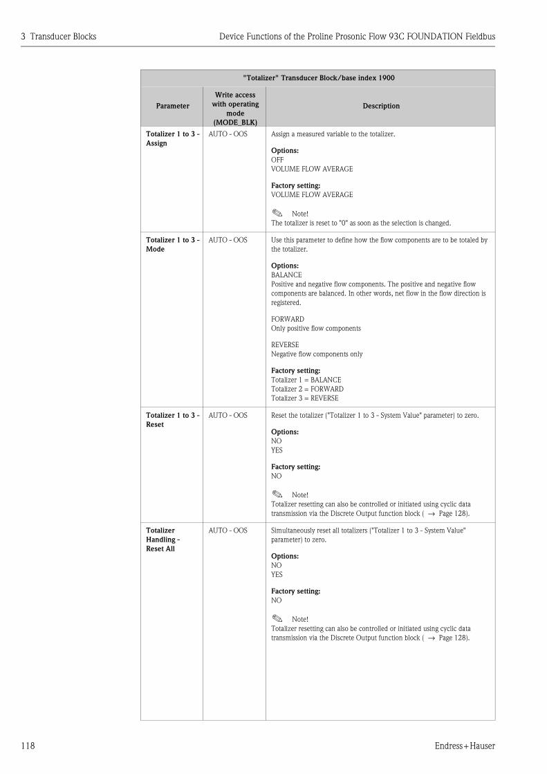
3 Transducer Blocks Device Functions of the Proline Prosonic Flow 93C FOUNDATION Fieldbus
118 Endress+Hauser
Totalizer 1 to 3 -
Assign
AUTO - OOS Assign a measured variable to the totalizer.
Options:
OFF
VOLUME FLOW AVERAGE
Factory setting:
VOLUME FLOW AVERAGE
! Note!
The totalizer is reset to "0" as soon as the selection is changed.
Totalizer 1 to 3 -
Mode
AUTO - OOS Use this parameter to define how the flow components are to be totaled by
the totalizer.
Options:
BALANCE
Positive and negative flow components. The positive and negative flow
components are balanced. In other words, net flow in the flow direction is
registered.
FORWARD
Only positive flow components
REVERSE
Negative flow components only
Factory setting:
Totalizer 1 = BALANCE
Totalizer 2 = FORWARD
Totalizer 3 = REVERSE
Totalizer 1 to 3 -
Reset
AUTO - OOS Reset the totalizer ("Totalizer 1 to 3 - System Value" parameter) to zero.
Options:
NO
YES
Factory setting:
NO
! Note!
Totalizer resetting can also be controlled or initiated using cyclic data
transmission via the Discrete Output function block ( → Page 128).
Totalizer
Handling -
Reset All
AUTO - OOS Simultaneously reset all totalizers ("Totalizer 1 to 3 - System Value"
parameter) to zero.
Options:
NO
YES
Factory setting:
NO
! Note!
Totalizer resetting can also be controlled or initiated using cyclic data
transmission via the Discrete Output function block ( → Page 128).
"Totalizer" Transducer Block/base index 1900
Parameter
Write access
with operating
mode
(MODE_BLK)
Description

Device Functions of the Proline Prosonic Flow 93C FOUNDATION Fieldbus 3 Transducer Blocks
Endress+Hauser 119
Totalizers
Handling -
Failsafe All
AUTO - OOS Use this parameter to define the common response of all totalizers in case of
error.
Options:
STOP
The totalizers are paused until the fault is rectified.
ACTUAL VALUE
The totalizers continue to count based on the current flow measured value.
The fault is ignored.
HOLD VALUE
The totalizers continue to count the flow based on the last valid flow value
(before the fault occurred).
Factory setting:
STOP
Amp. Device
Family
read only This parameter is only used for service purposes.
"Totalizer" Transducer Block/base index 1900
Parameter
Write access
with operating
mode
(MODE_BLK)
Description

4 Function blocks Device Functions of the Proline Prosonic Flow 93C FOUNDATION Fieldbus
120 Endress+Hauser
4 Function blocks
The function blocks contain the basic automation functions of the field device. We distinguish
between different function blocks, e.g. Analog Input function block, PID function block (PID
controller), etc.
Each of these function blocks is used to execute different application functions. This means that
local control functions, for example, can be carried out directly in the field, and device errors such
as amplifier errors are reported to the automation system automatically.
The function blocks process the input values in accordance with their specific algorithm and their
internally available parameters. They generate output values that are made available to other
function blocks for further processing by linking the individual function blocks with each
other.Analog Input function block
In the Analog Input function block (AI) the process variables from the Transducer Block are
prepared for the subsequent automation functions (e.g. scaling, limit value processing). The
automation function is defined by the connections of the outputs.
A0003800
OUT = output value and output status of the Analog Input function block
OUT
AI

Device Functions of the Proline Prosonic Flow 93C FOUNDATION Fieldbus 4 Function blocks
Endress+Hauser 121
4.1 Signal processing
The figure shows the internal structure of the Analog Input function blocks available:
A0014891
Fig. 3: Internal structure of the individual Analog Input function blocks
The Analog Input function blocks "Flow" and "Totalizer" receive their input values from the
Transducer Blocks. The parameter CHANNEL is used to select which input value is to be processed
in an Analog Input function block.
Factory-based configuration of the Transducer Blocks → Page 85 ff.
The parameter group SIMULATE allows you to replace the input value with a simulation value and
to activate simulation. By specifying the status and the simulation value the reaction of the complete
Analog Input function block can be tested.
! Note!
The simulation mode is activated by means of jumpers on the I/O board (→ Operating Instructions
for Prosonic Flow 93C FOUNDATION Fieldbus, BA00145D).
SIMULATE
XD_SCALE OUT_SCALE
XD_SCALE = OUT_SCALE
XD_SCALE OUT_SCALE
Direct
Indirect
Value, Status
Analog Input 1
L_TYPE
LOW_CUTCutoff
PV_FTIME
PV
MODE
AUTO
O/S
MAN
Filter
HI_HI_ALM
XD_SCALE OUT_SCALE
FIELD_VAL
Indirectsquare root
ALARM_HYS
HI_ALM
LO_LO_ALM
LO_ALM
Alarm detection
HI_HIHI
LOLO_LO
TB Flow
TB Totalizer
Analog Input 5
Analog Input 6
Analog Input 7
Analog Input 8
Analog Input 2
Analog Input 3
Analog Input 4
OUT
CHANNEL
CH 2
CH 7
CH 8
CH 9
CH 25
CH 28
CH 29
CH 30
CH 31
Volume Flow
Totalizer 1
Totalizer 2
Totalizer 3
Av. Vol. Flow
Av. Sound Velo.
Av. Flow Velo.
Signal Strength CH 1
Signal Strength CH 2

4 Function blocks Device Functions of the Proline Prosonic Flow 93C FOUNDATION Fieldbus
122 Endress+Hauser
The parameter L_TYPE is used to select the linearization type of the input or simulation value:
� Direct signal conversion
The input value is forwarded without conversion (XD_SCALE = OUT_SCALE). Select this option
if the input value is already in the physical unit you want.
� Indirect signal conversion
With this setting the input value is re-scaled linearly via the input scaling XD_SCALE to the
desired output range OUT_SCALE (further information on rescaling of the input value can be
found on → Page 125).
� Indirect signal conversion with square root
With this setting the input value is re-scaled via the parameter group XD_SCALE and
recalculated using a square root function. It is then rescaled again to the desired output range via
the parameter group OUT_SCALE.
The parameter LOW_CUT allows a limit value to be specified for the low flow cut off. The low flow
cut off is activated via the parameter IO_OPTS. If the converted primary value (PV) is below the
limit value then it is set to a value of "0".
In the parameter PV_FTIME a filter time can be specified for filtering the converted primary value
(PV). If a time of 0 seconds is specified then no filtration takes place.
The parameter group MODE_BLK is used to select the operating mode of the Analog Input function
block. If the operating mode MAN (manual) is selected then the output value OUT can be specified
directly.
The output value OUT is compared with warning and alarm limits (e.g. HI_LIM, LO_LO_LIM, etc.)
that can be entered via various parameters. If one of these limit values is violated then a limit value
process alarm (e.g. HI_ALM, LO_LO_ALM, etc.) is triggered.

Device Functions of the Proline Prosonic Flow 93C FOUNDATION Fieldbus 4 Function blocks
Endress+Hauser 123
4.2 Important functions and parameters of the Analog Input
function blocks
The most important functions and parameters of the Analog Input function blocks are listed below.
! Note!
All the FOUNDATION Fieldbus parameters available are described in the Operating Instructions
"FOUNDATION Fieldbus Overview" (BA013S) (acquired at: → www.endress.de → Download).
4.2.1 Selecting the operating mode
The operating mode is configured via the MODE_
BLK parameter group. The Analog Input function block supports the following operating modes:
� AUTO (automatic mode)
� MAN (manual mode)
� OOS (out of service)
! Note!
The block status OOS is also shown via the parameter BLOCK_ERR. In operating mode OOS, if
write protection is not enabled, you can access all the write parameters without restriction.
4.2.2 Assignment of the process variable
The Prosonic Flow 93C FOUNDATION Fieldbus has eight Analog Input function blocks. The
process variables of the Transducer Block that are to be processed are assigned via the parameter
CHANNEL.
Factory-based configuration of the Transducer Blocks → Page 85 ff.
4.2.3 Linearization types
In an Analog Input function block, the input value of a Transducer Block can be linearized using the
parameter L_TYPE. The following types of linearization are available:
� Direct
With this setting the measured value from the Transducer Block (input value) bypasses the
linearization function and is looped unchanged with the same unit through the Analog Input
function block.
� Indirect
With this setting the measured value from the Transducer Block (input value) is re-scaled linearly
via the input scaling XD_SCALE to the desired output range OUT_SCALE.
� Indirect Square Root
With this setting the measured value from the Transducer Block (input value) is re-scaled via the
parameter group XD_SCALE and recalculated using an evolution function. It is then rescaled
again to the desired output range via the parameter group OUT_SCALE.

4 Function blocks Device Functions of the Proline Prosonic Flow 93C FOUNDATION Fieldbus
124 Endress+Hauser
4.2.4 Selection of units
A change in the unit for a process variable is defined in the relevant Analog Input function block, in
the parameter group XD_SCALE via the element UNIT.
If an unsuitable unit is selected, the function block changes to the OOS mode (out of service).
! Note!
� If the "Direct" type of linearization was selected via the L_TYPE parameter, the setting of the
XD_SCALE and OUT_SCALE parameter groups must be identical; otherwise, the function block
remains in the OOS operating mode and the "BLOCK CONFIG ERROR" block error is displayed
in the BLOCK_ERROR parameter.
� The system units selected in the Transducer Blocks in question do not have any effect on the
setting of the system units in the Analog Input function block. The units are specified
independently of one another and must be configured separately. The unit selected in the
Transducer Blocks is only used for the local display, low flow cut off and for simulation.
! 4.2.5 Status of the output value OUT
The status of the parameter group OUT transmits to the subsequent function blocks the status of
the Analog Input function block and the validity of the output value OUT. The following status
values can be displayed during this process:
� GOOD_NON_CASCADE
The output value OUT is valid and can be used for further processing.
� UNCERTAIN
The output value OUT can only be used for further processing to a limited extent. The status
UNCERTAIN tells the downstream function blocks that a "notice message" is present in the
device, e.g. arising from active positive zero return or simulation.
� BAD
The output value OUT is invalid. The following causes are possible:
– The Analog Input function block is in the OOS operating mode.
– The "Flow" or "Totalizer" Transducer Block is in the OOS operating mode. The Analog Input
function block can only process the input value of the Transducer Block in question if the
operating mode is set to AUTO.
– A "fault message" is present in the device arising from a critical device error, e.g. an electronics
module defect.
! Note!
� The status of the device (block error) is displayed by means of the BLOCK_ERR parameter.
� Detailed information on the current device status is displayed via the "Diagnosis" Transducer
Block in the parameter "Diag. - Act.Sys.Condition". A list of all the error messages, including
remedial measures, can be found in the Operating Instructions for Prosonic Flow 93C
FOUNDATION Fieldbus (BA00145D).

Device Functions of the Proline Prosonic Flow 93C FOUNDATION Fieldbus 4 Function blocks
Endress+Hauser 125
4.2.6 Simulation of input/output
Certain parameters of the Analog Input function block allow simulation of the input and output of
the function block:
1. Simulation of the input of the Analog Input function block:
The parameter group SIMULATE can be used to specify the input value (measured value and
status). Since the simulation value runs through the entire function block, all the parameter
settings of the block can be checked.
! Hinweis!
If simulation is blocked by the jumper on the I/O board then simulation mode cannot be
activated in the parameter SIMULATE. In the Resource Block, the parameter BLOCK_ERROR
shows whether simulation of the Analog Input function block is possible.
2. Simulation of the output of the Analog Input function block:
Set the operating mode in the parameter group MODE_BLK to MAN and specify the desired
output value directly in the parameter OUT.
4.2.7 Diagnosis
The status of the device is displayed via the BLOCK_ERR parameter specified in the FOUNDATION
Fieldbus specification.
Detailed information on the current device status is displayed via the "Diagnosis" Transducer Block
in the manufacturer-specific parameter "Diag. - Act.Sys.Condition"
( → Page 98).
For more information on rectifying errors →See Operating Instructions for Prosonic Flow 93C
FOUNDATION Fieldbus (BA00145D), "Troubleshooting" section.
4.2.8 Rescaling the input value
In the Analog Input function block the input value or input range can be scaled in accordance with
the automation requirements.
Example:
� The measurement range of the sensor is 0 to 30 m³/h.
� The output range to the process control system should be 0 to 100%.
The Analog Input function block must be configured as follows:
� Select the input value in the parameter CHANNEL
Selection: Channel = 2 → Volume flow channel 1
� Parameter L_TYPE
Selection: L_TYPE = Indirect
The process variable "Average volume flow" from the "Channel 25" Transducer Block is rescaled
linearly via input scaling XD_SCALE to the desired output range OUT_SCALE.
� Parameter group XD_SCALE
XD_SCALE 0 % = 0
XD_SCALE 100 % = 30
XD_SCALE UNIT = m³/h

4 Function blocks Device Functions of the Proline Prosonic Flow 93C FOUNDATION Fieldbus
126 Endress+Hauser
� Parameter group OUT_SCALE
The result is that with an input value of, for example, 15 m³/h, a value of 50% is output via the
parameter OUT.
A0014779-EN
Fig. 4: Rescaling the input value (example)
4.2.9 Limit values
The full scale values are based on the output value OUT. If the output value OUT exceeds or does
not reach the defined limit values then an alarm is sent to the fieldbus host system via the limit value
process alarms. The following limit values can be defined:
� HI_HI_LIM (upper alarm limit)
� HI_LIM (upper pre-warning limit)
� LO_LO_LIM (lower alarm limit)
� LO_LIM (lower pre-warning limit)
4.2.10 Alarm detection and processing
Process alarms provide information on particular block statuses and block events. The status of the
process alarms is communicated to the fieldbus host system via the parameter BLOCK_ALM. The
parameter ACK_OPTION specifies whether an alarm must be acknowledged via the fieldbus host
system.
The following process alarms are generated by the Analog Input function block:
Block process alarms
A block process alarm is triggered via the BLOCK_ERR parameter. The parameter BLOCK_ALM is
used to show the block process alarms and communicate them to the fieldbus host system. The
following process alarms can be generated by the Analog Input function block:
� SIMULATE ACTIVE
� INPUT FAILURE
� OUT OF SERVICE
� BLOCK CONFIG ERROR
If the option of the process alarm (BLOCK ALM) has not been enabled in the parameter
ACK_OPTION, the process alarms must be acknowledged in the parameter BLOCK_ALM.
OUT_SCALE 0 % = 0
OUT_SCALE 100 % = 100
OUT_SCALE UNIT = %
OUT
50%
TransducerBlock
TRANSDUCER_CH1 XD_SCALE OUT_SCALE
0 00 0
30 100
100%
%
Analog Input Function Block
%100
Vol. FlowCh 1
m³/h
15 m³/h
0...30 m³/h

Device Functions of the Proline Prosonic Flow 93C FOUNDATION Fieldbus 4 Function blocks
Endress+Hauser 127
Limit value process alarms
If a limit value is infringed then the priority specified for the limit value alarm will be checked before
the limit value violation is communicated to the fieldbus host system. The priority that specifies the
action in the event of an active limit value violation is determined by the following parameters:
� HI_HI_PRI (upper alarm limit)
� HI_PRI (upper pre-warning limit)
� LO_LO_PRI (lower alarm limit)
� LO_PRI (lower pre-warning limit)
The status of the limit value process alarms is communicated to the fieldbus host system via the
following parameters:
� HI_HI_ALM (upper alarm limit)
� HI_ALM (upper pre-warning limit)
� LO_LO_ALMI (lower alarm limit)
� LO_ALM (lower pre-warning limit)
If the option of a limit value process alarm has not been enabled in the parameter ACK_OPTION
then this must be acknowledged directly in its parameter (see list).
! Note!
The parameter ALARM_SUM shows the current status of all the process alarms.

5 Discrete Output function block Device Functions of the Proline Prosonic Flow 93C FOUNDATION Fieldbus
128 Endress+Hauser
5 Discrete Output function block
The Discrete Output function block (DO, Discrete Output) processes a discrete setpoint value
received from an upstream function block or higher level process control system, with which
various instrument functions (e.g. zero point adjustment or totalizer reset) can be initiated in the
subsequent Transducer Block.
5.1 Signal processing
The figure shows the internal structure of the Discrete Output function blocks Prosonic Flow 93C
FOUNDATION Fieldbus:
A0004771-en
Fig. 5: Signal processing in the Discrete Output function block
In the CAS operating mode (cascade operation), the Discrete Output function block receives, via
the function block input CAS_IN_D, a discrete signal from an upstream function block. This signal
controls the setpoint value (parameter SP_D) of the function block, and after internal calculation is
sent as an output signal (parameter OUT_D) to the Transducer Block for control of instrument
functions (e.g. zero point adjustment). The output value and status of the Discrete Output func-
tion block is communicated to the upstream block via the output BKCAL_OUT_D.
Signal processing in the RCAS operating mode (remote cascade operation) is largely identical to the
CAS operating mode. However, in this operating mode, control of the parameter SP_D does not take
place via an upstream function block but through a fieldbus host system.
A0003816-en
CAS_IN _D = Remote setpoint value from another function block
OUT_D = Discrete output value and status
BKCAL_OUT_D = Discrete output value and status required by BKCAL_IN_D input of another block for output
OUT_D
BKCAL_OUT_D
CAS_IN_D
DO
RCAS_IN_D
IO_OPTS
SIMULATE_D SIMULATE_D
DiscreteInput
Transducer Blocks
DiscreteOutput
MODE_BLK
CAS_IN_D
PV_D
BKCAL_OUT_D
OUT_D
(Mode Man)(Mode Auto)
SP_D
Discrete Output Function Block
Invert.
RCAS_OUT_D
(Mode CAS)
(Mode RCAS)

Device Functions of the Proline Prosonic Flow 93C FOUNDATION Fieldbus 5 Discrete Output function block
Endress+Hauser 129
The output value and status of the Discrete Output function block is communicated to the process
control system as an answer message via parameter RCAS_OUT_D.
In the AUTO operating mode (automatic operation), the set point value (parameter SP_D) is
prescribed directly in the Discrete Output function block. In this case, the parameter CAS_IN_D is
not taken into consideration in the internal calculation.
In the MAN operating mode (HAND), the output value (parameter OUT_D) can be prescribed
directly in the Discrete Output function block. No internal calculation takes place.
5.2 Important functions and parameters of the Discrete
Output function block
The most important functions and parameters of the Discrete Output function block are listed
below.
! Note!
All the FOUNDATION Fieldbus parameters available are described in the Operating Instructions
"FOUNDATION Fieldbus Overview" (BA013S) (acquired at: → www.endress.de → Download).
5.2.1 Selecting the operating mode
The operating mode is configured via the MODE_BLK parameter group. The Discrete Output
function block supports the following operating modes:
� AUTO
� MAN
� CAS
� RCAS
� OOS
5.2.2 Safety behavior
There is a safety default available (fault state) for the Discrete Output function block.
This is activated when a fault condition (of the corresponding valid set point value) exists longer
than defined in the parameter FSTATE_TIME, or when the parameter SET_FSTATE in the Resource
Block is activated. The safety operation is determined via the parameters FSTATE_TIME,
FSTATE_VAL_D, and IO_OPTS.
5.2.3 Assignment between the Discrete Output function block and the Transducer Block
The assignment or connection between the Discrete Output function block and the Transducer
Block takes place in the Discrete Output function block via the parameter CHANNEL.
→ Parameter CHANNEL → 16 (= Discrete Output function block)

5 Discrete Output function block Device Functions of the Proline Prosonic Flow 93C FOUNDATION Fieldbus
130 Endress+Hauser
5.2.4 Values for the parameters CAS_IN_D, RCAS_IN_D, OUT_D and SP_D
Via the Discrete Output function block, different instrument functions in the Transducer Block can
be initiated via manufacturer-specific, fixed set point values from an upstream function block.
Here it must be observed that the desired function is only then executed when a status change from
the value 0 (Discrete state 0) to the corresponding function value (following table) takes place. The
value 0 always serves as the starting point for the corresponding control of instrument functions. A
status change from a value not equal to zero to another value has no effect.
Input assignment of the CAS_IN_D, RCAS_IN_D, OUT_D, SP_D parameters
Example for controlling positive zero return via the Discrete Output function block.
The following example shows how positive zero return can be activated or deactivated via the
Discrete Output function block during a cleaning procedure.
1. In the first step, the connection between the Discrete Output function block and the
Transducer Block must be established. Here, the value 16 must be assigned to the
parameter CHANNEL in the Discrete Output function block.
2. In the CAS operating mode, the Discrete Output function block processes the set point value
specified at the input CAS_IN_D by the upstream function block and transfers it to the
Transducer Block.
Status changes Action
Discrete state 0 → Discrete state 1 Reserved
Discrete state 0 → Discrete state 2 Positive zero return channel 1: On
Discrete state 0 → Discrete state 3 Positive zero return channel 1: Off
Discrete state 0 → Discrete state 4 Zero point adjustment channel 1
Discrete state 0 → Discrete state 5 Reserved
Discrete state 0 → Discrete state 6 Reserved
Discrete state 0 → Discrete state 7 Reset totalizers 1, 2, 3
Discrete state 0 → Discrete state 8 Reset totalizer 1
Discrete state 0 → Discrete state 9 Reset totalizer 2
Discrete state 0 → Discrete state 10 Reset totalizer 3
Discrete state 0 → Discrete state 11 Reserved
Discrete state 0 → Discrete state 12 Reserved
Discrete state 0 → Discrete state 13 Reserved
Discrete state 0 → Discrete state 14 Reserved
Discrete state 0 → Discrete state 15 Reserved
Discrete state 0 → Discrete state 16 Positive zero return channel 2: On
Discrete state 0 → Discrete state 17 Positive zero return channel 2: Off
Discrete state 0 → Discrete state 18 Zero point adjustment channel 2
Discrete state 0 → Discrete state 27 Permanent storage: Off
Discrete state 0 → Discrete state 28 Permanent storage: On

Device Functions of the Proline Prosonic Flow 93C FOUNDATION Fieldbus 6 Additional function blocks
Endress+Hauser 131
Activating the positive zero return channel 1
With a starting value of 0 (Discrete state 0), positive zero return is activated by a status change
from 0 → 2 at input CAS_IN_D.
Deactivating the positive zero return channel 1
Positive zero return can only then be deactivated when the input value at CAS_IN_D has first
been set to output value 0 (Discrete state 0). Only then can positive zero return be deactivated
through a status change from 0 → 3 at input CAS_IN_D.
6 Additional function blocks
! Note!
Additional function blocks such as the PID, Arithmetic, Input Selector, Signal Characterizer and
Integrator function block are described in the "FOUNDATION Fieldbus Overview" (BA013S)
Operating Instructions (acquired at: → www.endress.de → download).

6 Additional function blocks Device Functions of the Proline Prosonic Flow 93C FOUNDATION Fieldbus
132 Endress+Hauser

Device Functions of the Proline Prosonic Flow 93C FOUNDATION Fieldbus 7 Index FOUNDATION Fieldbus
Endress+Hauser 133
7 Index FOUNDATION Fieldbus
AAccess - Code
Transducer Blocks "Channel 1" and "Channel 2" . . . . . 87
Access - Code Counter
"Display" Transducer Block . . . . . . . . . . . . . . . . . . . . 101
Access counter . . . . . . . . . . . . . . . . . . . . . . . . . . . . . . . . . 22
Add. Line - 100%-Value
"Display" Transducer Block . . . . . . . . . . . . . . . . . . . . 108
Add. Line - Assign
"Display" Transducer Block . . . . . . . . . . . . . . . . . . . . 108
Add. Line - Display Mode
"Display" Transducer Block . . . . . . . . . . . . . . . . . . . . 109
Add. Line - Format
"Display" Transducer Block . . . . . . . . . . . . . . . . . . . . 109
Add. Line Multiplex - 100%-Value
"Display" Transducer Block . . . . . . . . . . . . . . . . . . . . 110
Add. Line Multiplex - Assign
"Display" Transducer Block . . . . . . . . . . . . . . . . . . . . 110
Add. Line Multiplex - Display Mode
"Display" Transducer Block . . . . . . . . . . . . . . . . . . . . 111
Add. Line Multiplex - Format
"Display" Transducer Block . . . . . . . . . . . . . . . . . . . . 111
Additional line
100% Value . . . . . . . . . . . . . . . . . . . . . . . . . . . . . . . 108
100% value (multiplex) . . . . . . . . . . . . . . . . . . . . . . . 110
Assign . . . . . . . . . . . . . . . . . . . . . . . . . . . . . . . . . . . . 108
Assign (multiplex) . . . . . . . . . . . . . . . . . . . . . . . . . . . 110
Display mode . . . . . . . . . . . . . . . . . . . . . . . . . . . . . . 109
Display mode (multiplex) . . . . . . . . . . . . . . . . . . . . . 111
Format . . . . . . . . . . . . . . . . . . . . . . . . . . . . . . . . . . . 109
Format (multiplex) . . . . . . . . . . . . . . . . . . . . . . . . . . 111
Alarm delay . . . . . . . . . . . . . . . . . . . . . . . . . . . . . . . . . . . 99
Alarm detection
AI function block . . . . . . . . . . . . . . . . . . . . . . . . . . . 126
Resource Block . . . . . . . . . . . . . . . . . . . . . . . . . . . . . . 80
Transducer Block . . . . . . . . . . . . . . . . . . . . . . . . . . . . 86
Alarm processing
AI function block . . . . . . . . . . . . . . . . . . . . . . . . . . . 126
Resource Block . . . . . . . . . . . . . . . . . . . . . . . . . . . . . . 80
Transducer Blocks . . . . . . . . . . . . . . . . . . . . . . . . . . . . 86
Amp. - HW Identification
Resource Block . . . . . . . . . . . . . . . . . . . . . . . . . . . . . . 81
Amp. - HW Rev.Number
Resource Block . . . . . . . . . . . . . . . . . . . . . . . . . . . . . . 81
Amp. - Language Group
Resource Block . . . . . . . . . . . . . . . . . . . . . . . . . . . . . . 81
Amp. - Prod.Number
Resource Block . . . . . . . . . . . . . . . . . . . . . . . . . . . . . . 81
Amp. - SW Identification
Resource Block . . . . . . . . . . . . . . . . . . . . . . . . . . . . . . 81
Amp. - SW Rev.No. T-DAT
Resource Block . . . . . . . . . . . . . . . . . . . . . . . . . . . . . . 81
Amp. - SW Rev.Number
Resource Block . . . . . . . . . . . . . . . . . . . . . . . . . . . . . . 81
Amp. Device Family
"Display" Transducer Block . . . . . . . . . . . . . . . . . . . . 115
"Totalizer" Transducer Block . . . . . . . . . . . . . . . . . . . 119
Transducer Blocks "Channel 1" and "Channel 2" . . . . . 97
Amp. Device Family - Transducer Block "Diagnosis" . . . . 100
Amplifier
Hardware identification number . . . . . . . . . . . . . . . . . 81
Hardware revision number . . . . . . . . . . . . . . . . . . . . . 81
Language Group . . . . . . . . . . . . . . . . . . . . . . . . . . . . . 81
Production number . . . . . . . . . . . . . . . . . . . . . . . . . . . 81
Software identification number . . . . . . . . . . . . . . . . . . 81
Software revision number . . . . . . . . . . . . . . . . . . . . . . 81
Analog Input function block
Alarm detection, processing . . . . . . . . . . . . . . . . . . . . 126
Diagnosis . . . . . . . . . . . . . . . . . . . . . . . . . . . . . . . . . 125
General description . . . . . . . . . . . . . . . . . . . . . . . . . . 120
Limit values . . . . . . . . . . . . . . . . . . . . . . . . . . . . . . . 126
Rescaling . . . . . . . . . . . . . . . . . . . . . . . . . . . . . . . . . . 125
Signal processing . . . . . . . . . . . . . . . . . . . . . . . . . . . . 121
Simulation of input/output . . . . . . . . . . . . . . . . . . . . 125
Status, output value OUT . . . . . . . . . . . . . . . . . . . . . 124
Assign
DO function block . . . . . . . . . . . . . . . . . . . . . . . . . . . 129
Totalizer 1 to 3 . . . . . . . . . . . . . . . . . . . . . . . . . . . . . 118
BBacklight Display . . . . . . . . . . . . . . . . . . . . . . . . . . . . . . 103
Base index 1700 Transducer Block "Service" . . . . . . . . . . 101
Block model . . . . . . . . . . . . . . . . . . . . . . . . . . . . . . . . . . . 77
Block output values
Transducer Block . . . . . . . . . . . . . . . . . . . . . . . . . . . . 85
CCable length . . . . . . . . . . . . . . . . . . . . . . . . . . . . . . . . . . . 96
Calibration Data - Calibration Factor
Transducer Blocks "Channel 1" and "Channel 2" . . . . . 97
Calibration Data - Correction Factor
Transducer Blocks "Channel 1" and "Channel 2" . . . . . 97
Calibration Data - Zero Point
Transducer Blocks "Channel 1" and "Channel 2" . . . . . 97
Calibration factor . . . . . . . . . . . . . . . . . . . . . . . . . . . . . . . 97
Code Access counter . . . . . . . . . . . . . . . . . . . . . . . . . . . . 22
Code entry
See Access - Code
Config. - Backlight
"Display" Transducer Block . . . . . . . . . . . . . . . . . . . . 103
Configuration - Contrast LCD
"Display" Transducer Block . . . . . . . . . . . . . . . . . . . . 103
Configuration - Display Damping
"Display" Transducer Block . . . . . . . . . . . . . . . . . . . . 103
Configuration - Language
"Display" Transducer Block . . . . . . . . . . . . . . . . . . . . 102
Configuration - Xline Calculated
"Display" Transducer Block . . . . . . . . . . . . . . . . . . . . 103
Contrast LCD . . . . . . . . . . . . . . . . . . . . . . . . . . . . . . . . . 103
Correction factor . . . . . . . . . . . . . . . . . . . . . . . . . . . . . . . 97

7 Index FOUNDATION Fieldbus Device Functions of the Proline Prosonic Flow 93C FOUNDATION Fieldbus
134 Endress+Hauser
DDamping
Display . . . . . . . . . . . . . . . . . . . . . . . . . . . . . . . . . . 103
Flow . . . . . . . . . . . . . . . . . . . . . . . . . . . . . . . . . . . . . 89
Data backup . . . . . . . . . . . . . . . . . . . . . . . . . . . . . . . . . . 18
Define failsafe mode (totalizer) . . . . . . . . . . . . . . . . . . . . 119
Device Software
Resource Block . . . . . . . . . . . . . . . . . . . . . . . . . . . . . 81
Diagnosis
AI function block . . . . . . . . . . . . . . . . . . . . . . . . . . . 125
Transducer Block . . . . . . . . . . . . . . . . . . . . . . . . . . . . 86
Diagnosis - Actual System Condition
"Diagnosis" Transducer Block . . . . . . . . . . . . . . . . . . . 98
Diagnosis - Previous System Condition
"Diagnosis" Transducer Block . . . . . . . . . . . . . . . . . . . 98
Discrete Output function block . . . . . . . . . . . . . . . . . . . 128
Safety behavior . . . . . . . . . . . . . . . . . . . . . . . . . . . . 129
Values for CAS_IN_D, RCAS_IN_D, OUT_D and SP_D . .
130
Display
Backlight . . . . . . . . . . . . . . . . . . . . . . . . . . . . . . . . . 103
Signal strength . . . . . . . . . . . . . . . . . . . . . . . . . . . . . . 88
Test . . . . . . . . . . . . . . . . . . . . . . . . . . . . . . . . . . . . . 104
FFunction blocks . . . . . . . . . . . . . . . . . . . . . . . . . . . . . . . 120
II/O - HW Identification
Resource Block . . . . . . . . . . . . . . . . . . . . . . . . . . . . . 81
I/O - HW Rev. Number
Resource Block . . . . . . . . . . . . . . . . . . . . . . . . . . . . . 81
I/O - Prod.Number
Resource Block . . . . . . . . . . . . . . . . . . . . . . . . . . . . . 81
I/O - SW Identification
Resource Block . . . . . . . . . . . . . . . . . . . . . . . . . . . . . 81
I/O - SW Rev. Number
Resource Block . . . . . . . . . . . . . . . . . . . . . . . . . . . . . 81
I/O - Type
Resource Block . . . . . . . . . . . . . . . . . . . . . . . . . . . . . 81
I/O Module
Device Software . . . . . . . . . . . . . . . . . . . . . . . . . . . . . 81
Hardware identification number . . . . . . . . . . . . . . . . . 81
Hardware revision number . . . . . . . . . . . . . . . . . . . . . 81
Production number . . . . . . . . . . . . . . . . . . . . . . . . . . 81
Software identification number . . . . . . . . . . . . . . . . . . 81
Software revision number . . . . . . . . . . . . . . . . . . . . . 81
Identification number
Amplifier hardware . . . . . . . . . . . . . . . . . . . . . . . . . . 81
Amplifier software . . . . . . . . . . . . . . . . . . . . . . . . . . . 81
I/O module hardware . . . . . . . . . . . . . . . . . . . . . . . . 81
I/O module software . . . . . . . . . . . . . . . . . . . . . . . . . 81
Info Line - 100%-Value
"Display" Transducer Block . . . . . . . . . . . . . . . . . . . 112
Info Line - Display Mode
"Display" Transducer Block . . . . . . . . . . . . . . . . . . . 113
Info Line - Format
"Display" Transducer Block . . . . . . . . . . . . . . . . . . . 113
Info Line Assign
"Display" Transducer Block . . . . . . . . . . . . . . . . . . . . 112
Info Line Multiplex
- Assign
"Display" Transducer Block . . . . . . . . . . . . . . . . . 114
Info Line Multiplex - 100%-Value
"Display" Transducer Block . . . . . . . . . . . . . . . . . . . . 114
Info Line Multiplex - Display Mode
"Display" Transducer Block . . . . . . . . . . . . . . . . . . . . 115
Info Line Multiplex - Format
"Display" Transducer Block . . . . . . . . . . . . . . . . . . . . 115
Information line
100% Value . . . . . . . . . . . . . . . . . . . . . . . . . . . . . . . 112
100% value (multiplex) . . . . . . . . . . . . . . . . . . . . . . 114
Assign . . . . . . . . . . . . . . . . . . . . . . . . . . . . . . . . . . . 112
Assign (multiplex) . . . . . . . . . . . . . . . . . . . . . . . . . . 114
Display mode . . . . . . . . . . . . . . . . . . . . . . . . . . . . . . 113
Display mode (multiplex) . . . . . . . . . . . . . . . . . . . . . 115
Format . . . . . . . . . . . . . . . . . . . . . . . . . . . . . . . . . . . 113
Format (multiplex) . . . . . . . . . . . . . . . . . . . . . . . . . . 115
LLanguage . . . . . . . . . . . . . . . . . . . . . . . . . . . . . . . . . . . . 102
Language group amplifier . . . . . . . . . . . . . . . . . . . . . . . . . 81
Limit values AI function block . . . . . . . . . . . . . . . . . . . . 126
Liquid
Max. sound velocity . . . . . . . . . . . . . . . . . . . . . . . . . . 96
Min. sound velocity . . . . . . . . . . . . . . . . . . . . . . . . . . 96
Options. . . . . . . . . . . . . . . . . . . . . . . . . . . . . . . . . . . . 95
Sound velocity . . . . . . . . . . . . . . . . . . . . . . . . . . . . . . 95
Temperature . . . . . . . . . . . . . . . . . . . . . . . . . . . . . . . 95
Liquid Data - Liquid
Transducer Blocks "Channel 1" and "Channel 2" . . . . . 95
Liquid Data - Max. Sound Velocity
Transducer Blocks "Channel 1" and "Channel 2" . . . . . 96
Liquid Data - Min. Sound Velocity
Transducer Blocks "Channel 1" and "Channel 2" . . . . . 96
Liquid Data - Sound Velocity
Transducer Blocks "Channel 1" and "Channel 2" . . . . . 95
Liquid Data - Temperature
Transducer Blocks "Channel 1" and "Channel 2" . . . . . 95
Liquid Data - Unit Max. Sound Velocity
Transducer Blocks "Channel 1" and "Channel 2" . . . . . 96
Liquid Data - Unit Min. Sound Velocity
Transducer Blocks "Channel 1" and "Channel 2" . . . . . 96
Liquid Data - Unit Sound Velocity
Transducer Blocks "Channel 1" and "Channel 2" . . . . . 96
Liquid Data - Unit Temperature
Transducer Blocks "Channel 1" and "Channel 2" . . . . . 95
Low flow cut off
Assign . . . . . . . . . . . . . . . . . . . . . . . . . . . . . . . . . . . . 90
Off-value . . . . . . . . . . . . . . . . . . . . . . . . . . . . . . . . . . 91
On-value . . . . . . . . . . . . . . . . . . . . . . . . . . . . . . . . . . 90
Unit . . . . . . . . . . . . . . . . . . . . . . . . . . . . . . . . . . . . . . 91
Low Flow Cut Off - Assign
Transducer Blocks "Channel 1" and "Channel 2" . . . . . 90
Low Flow Cut Off - Unit
Transducer Blocks "Channel 1" and "Channel 2" . . . . . 91
Low Flow Cut Off - Off-Value
Transducer Blocks "Channel 1" and "Channel 2" . . . . . 91

Device Functions of the Proline Prosonic Flow 93C FOUNDATION Fieldbus Stichwortverzeichnis
Endress+Hauser 135
Low Flow Cut Off - On-Value
Transducer Blocks "Channel 1" and "Channel 2" . . . . . 90
MMain line
100% Value . . . . . . . . . . . . . . . . . . . . . . . . . . . . . . . 105
100% value (multiplex) . . . . . . . . . . . . . . . . . . . . . . . 106
Assign . . . . . . . . . . . . . . . . . . . . . . . . . . . . . . . . . . . . 105
Assign (multiplex) . . . . . . . . . . . . . . . . . . . . . . . . . . . 106
Format . . . . . . . . . . . . . . . . . . . . . . . . . . . . . . . . . . . 106
Format (multiplex) . . . . . . . . . . . . . . . . . . . . . . . . . . 107
Main Line - 100%-Value
"Display" Transducer Block . . . . . . . . . . . . . . . . . . . . 105
Main Line - Assign
"Display" Transducer Block . . . . . . . . . . . . . . . . . . . . 105
Main Line - Format
"Display" Transducer Block . . . . . . . . . . . . . . . . . . . . 106
Main Line Multiplex - 100%-Value
"Display" Transducer Block . . . . . . . . . . . . . . . . . . . . 106
Main Line Multiplex - Assign
"Display" Transducer Block . . . . . . . . . . . . . . . . . . . . 106
Main Line Multiplex - Format
"Display" Transducer Block . . . . . . . . . . . . . . . . . . . . 107
Main values (calculated) . . . . . . . . . . . . . . . . . . . . . . . . . 103
Measurement method . . . . . . . . . . . . . . . . . . . . . . . . . . . 96
Mode
Totalizer 1 to 3 . . . . . . . . . . . . . . . . . . . . . . . . . . . . . 118
OOperating hours . . . . . . . . . . . . . . . . . . . . . . . . . . . . . . . 100
Operation - Test Display
"Display" Transducer Block . . . . . . . . . . . . . . . . . . . . 104
Operation mode
AI function block . . . . . . . . . . . . . . . . . . . . . . . . . . . 123
DO function block . . . . . . . . . . . . . . . . . . . . . . . . . . 129
Resource Block . . . . . . . . . . . . . . . . . . . . . . . . . . . . . . 79
Transducer Block . . . . . . . . . . . . . . . . . . . . . . . . . . . . 85
PParameter
Discrete Output function block . . . . . . . . . . . . . . . . . 131
Resource Block . . . . . . . . . . . . . . . . . . . . . . . . . . . . . . 81
Pipe
Diameter . . . . . . . . . . . . . . . . . . . . . . . . . . . . . . . . . . 94
Nominal diameter . . . . . . . . . . . . . . . . . . . . . . . . . . . . 93
Standard . . . . . . . . . . . . . . . . . . . . . . . . . . . . . . . . . . . 93
Wall thickness . . . . . . . . . . . . . . . . . . . . . . . . . . . . . . 94
Pipe Data - Nominal Diameter
Transducer Blocks "Channel 1" and "Channel 2" . . . . . 93
Pipe Data - Pipe Diameter
Transducer Blocks "Channel 1" and "Channel 2" . . . . . 94
Pipe Data - Pipe Standard
Transducer Blocks "Channel 1" and "Channel 2" . . . . . 93
Pipe Data - Unit Nominal Diameter
Transducer Blocks "Channel 1" and "Channel 2" . . . . . 93
Pipe Data - Unit Pipe Diameter
Transducer Blocks "Channel 1" and "Channel 2" . . . . . 94
Pipe Data - Unit Reference Value
Transducer Blocks "Channel 1" and "Channel 2" . . . . . 94
Pipe Data - Unit Wall Thickness
Transducer Blocks "Channel 1" and "Channel 2" . . . . . 94
Pipe Data - Wall Thickness
Transducer Blocks "Channel 1" and "Channel 2" . . . . . 94
Positive zero return . . . . . . . . . . . . . . . . . . . . . . . . . . . . . 90
Pressure shock suppression . . . . . . . . . . . . . . . . . . . . 91, 92
Process - Pressure Shock Suppression
Transducer Blocks "Channel 1" and "Channel 2" . 91, 92
Process variable assignment
AI function block . . . . . . . . . . . . . . . . . . . . . . . . . . . 123
Production number
Amplifier . . . . . . . . . . . . . . . . . . . . . . . . . . . . . . . . . . . 81
I/O Module . . . . . . . . . . . . . . . . . . . . . . . . . . . . . . . . 81
RRescaling the input value (AI funct. block) . . . . . . . . . . . . 125
Reset
All totalizers . . . . . . . . . . . . . . . . . . . . . . . . . . . . . . . 118
System . . . . . . . . . . . . . . . . . . . . . . . . . . . . . . . . . . . . 99
Totalizer 1 to 3 . . . . . . . . . . . . . . . . . . . . . . . . . . . . . 118
Resource Block . . . . . . . . . . . . . . . . . . . . . . . . . . . . . . . . . 79
Resource block block status . . . . . . . . . . . . . . . . . . . . . . . . 79
Revision number
Amplifier hardware . . . . . . . . . . . . . . . . . . . . . . . . . . . 81
Amplifier software . . . . . . . . . . . . . . . . . . . . . . . . . . . . 81
SSelecting units
Volume flow . . . . . . . . . . . . . . . . . . . . . . . . . . . . . . . . 88
Sensor
Cable length . . . . . . . . . . . . . . . . . . . . . . . . . . . . . . . . 96
Serial number . . . . . . . . . . . . . . . . . . . . . . . . . . . . . . . 81
Type (selection) . . . . . . . . . . . . . . . . . . . . . . . . . . . . . . 96
Sensor - Serial Number
Resource Block . . . . . . . . . . . . . . . . . . . . . . . . . . . . . . 81
Sensor installation direction . . . . . . . . . . . . . . . . . . . . . . . 89
Sensor Param. - Cable Length
Transducer Blocks "Channel 1" and "Channel 2" . . . . . 96
Sensor Param. - Measurement
Transducer Blocks "Channel 1" and "Channel 2" . . . . . 96
Sensor Param. - Sensor Type
Transducer Blocks "Channel 1" and "Channel 2" . . . . . 96
Sensor, installation direction . . . . . . . . . . . . . . . . . . . . . . . 89
Serial number sensor . . . . . . . . . . . . . . . . . . . . . . . . . . . . 81
Signal processing
AI function block . . . . . . . . . . . . . . . . . . . . . . . . . . . 121
DO function block . . . . . . . . . . . . . . . . . . . . . . . . . . . 128
Transducer Block . . . . . . . . . . . . . . . . . . . . . . . . . . . . 83
Simulation
AI function block . . . . . . . . . . . . . . . . . . . . . . . . . . . 125
Error . . . . . . . . . . . . . . . . . . . . . . . . . . . . . . . . . . . . . . 99
Measured variable . . . . . . . . . . . . . . . . . . . . . . . . . . . . 97
Resource Block . . . . . . . . . . . . . . . . . . . . . . . . . . . . . . 80
Value measured variable . . . . . . . . . . . . . . . . . . . . . . . 97
Simulation - Measurand
Transducer Blocks "Channel 1" and "Channel 2" . . . . . 97
Simulation - Unit
Transducer Blocks "Channel 1" and "Channel 2" . . . . . 97
Simulation - Value Measurand
Transducer Blocks "Channel 1" and "Channel 2" . . . . . 97
7 Index FOUNDATION Fieldbus Device Functions of the Proline Prosonic Flow 93C FOUNDATION Fieldbus
136 Endress+Hauser
System - Alarm Delay
"Diagnosis" Transducer Block . . . . . . . . . . . . . . . . . . . 99
System - Operation Time
"Diagnosis" Transducer Block . . . . . . . . . . . . . . . . . . 100
System - Reset
"Diagnosis" Transducer Block . . . . . . . . . . . . . . . . . . . 99
System - Simulation Failsafe Mode
"Diagnosis" Transducer Block . . . . . . . . . . . . . . . . . . . 99
System - Troubleshooting
"Diagnosis" Transducer Block . . . . . . . . . . . . . . . . . . 100
System condition
Actual . . . . . . . . . . . . . . . . . . . . . . . . . . . . . . . . . . . . 98
Previous . . . . . . . . . . . . . . . . . . . . . . . . . . . . . . . . . . 98
System Param. - Adjust Zeropoint
Transducer Blocks "Channel 1" and "Channel 2" . . . . 90
System Param. - Flow Damping
Transducer Blocks "Channel 1" and "Channel 2" . . . . 89
System Param. - Installation Direction Sensor
Transducer Blocks "Channel 1" and "Channel 2" . . . . 89
System Param. -Positive Zero Return
Transducer Blocks "Channel 1" and "Channel 2" . . . . 90
System Unit - Length
Transducer Blocks "Channel 1" and "Channel 2" . . . . 89
System Unit - Viscosity
Transducer Blocks "Channel 1" and "Channel 2" . . . . 89
System Unit - Volume Flow
Transducer Blocks "Channel 1" and "Channel 2" . . . . 88
System Unit Temperature
Transducer Blocks "Channel 1" and "Channel 2" . . . . 88
System Value - Signal Strength
Transducer Blocks "Channel 1" and "Channel 2" . . . . 88
TT-DAT
Amplifier software revision number . . . . . . . . . . . . . . 81
Loading/saving data . . . . . . . . . . . . . . . . . . . . . . . . . 100
Save/load (data back-up, e.g. for replacing devices) . . 18
T-DAT - Save/Load
"Diagnosis" Transducer Block . . . . . . . . . . . . . . . . . . 100
Test display . . . . . . . . . . . . . . . . . . . . . . . . . . . . . . . . . . 104
Tot. 1 to 3 - Assign
"Totalizer" Transducer Block . . . . . . . . . . . . . . . . . . 118
Tot. 1 to 3 - Mode
"Totalizer" Transducer Block . . . . . . . . . . . . . . . . . . 118
Tot. 1 to 3 - Sum
"Totalizer" Transducer Block . . . . . . . . . . . . . . 117, 118
Totalizer 1 to 3
Assign . . . . . . . . . . . . . . . . . . . . . . . . . . . . . . . . . . . 118
Display value . . . . . . . . . . . . . . . . . . . . . . . . . . . . . . 117
Mode . . . . . . . . . . . . . . . . . . . . . . . . . . . . . . . . . . . 118
Reset . . . . . . . . . . . . . . . . . . . . . . . . . . . . . . . . . . . . 118
Unit . . . . . . . . . . . . . . . . . . . . . . . . . . . . . . . . . . . . . 117
Totalizer Handling
Reset All . . . . . . . . . . . . . . . . . . . . . . . . . . . . . . . . . 118
Totalizer Handling - Failsafe All
"Totalizer" Transducer Block . . . . . . . . . . . . . . . . . . 119
Transducer
Block . . . . . . . . . . . . . . . . . . . . . . . . . . . . . . . . . . . . . 82
Transducer Block
"Diagnosis" Transducer Block . . . . . . . . . . . . . . . . . . . 98
Transducer Blocks . . . . . . . . . . . . . . . . . . . . . . . . . . . . . . 82
Alarm detection, processing . . . . . . . . . . . . . . . . . . . . 86
Diagnostics (error messages) . . . . . . . . . . . . . . . . . . . . 86
E+H parameters . . . . . . . . . . . . . . . . . . . . . . . . . . . . . 87
FOUNDATION Fieldbus parameters . . . . . . . . . . . . . . 87
Transducer Blocks "Channel 1" and "Channel 2" . . . . . . . 87
Troubleshooting (EEPROM) . . . . . . . . . . . . . . . . . . . . . . 100
Type of linearization
AI function block . . . . . . . . . . . . . . . . . . . . . . . . . . . 123
UUn-/Locking - Access Code
"Diagnosis" Transducer Block . . . . . . . . . . . . . . . . . . . 98
"Display" Transducer Block . . . . . . . . . . . . . . . . . . . . 101
"Totalizer" Transducer Block . . . . . . . . . . . . . . . . . . 116
Un-/Locking - Access Status
"Diagnosis" Transducer Block . . . . . . . . . . . . . . . . . . . 98
"Display" Transducer Block . . . . . . . . . . . . . . . . . . . . 101
"Totalizer" Transducer Block . . . . . . . . . . . . . . . . . . 116
Un-/Locking - Define Private Code
"Display" Transducer Block . . . . . . . . . . . . . . . . . . . . 102
Unit (display)
Max. sound velocity (liquid) . . . . . . . . . . . . . . . . . . . . 96
Min. sound velocity (liquid) . . . . . . . . . . . . . . . . . . . . 96
Nominal diameter . . . . . . . . . . . . . . . . . . . . . . . . . . . 93
Pipe diameter . . . . . . . . . . . . . . . . . . . . . . . . . . . . . . . 94
Reference value . . . . . . . . . . . . . . . . . . . . . . . . . . . . . 94
Simulation measurand . . . . . . . . . . . . . . . . . . . . . . . . 97
Sound velocity (liquid) . . . . . . . . . . . . . . . . . . . . . . . . 96
Temperature (liquid) . . . . . . . . . . . . . . . . . . . . . . . . . 95
Wall thickness (pipe) . . . . . . . . . . . . . . . . . . . . . . . . . 94
Unit (selection)
Length . . . . . . . . . . . . . . . . . . . . . . . . . . . . . . . . . . . . 89
Temperature . . . . . . . . . . . . . . . . . . . . . . . . . . . . . . . 88
Totalizer 1 to 3 . . . . . . . . . . . . . . . . . . . . . . . . . . . . 117
Viscosity . . . . . . . . . . . . . . . . . . . . . . . . . . . . . . . . . . . 89
Units
AI function block . . . . . . . . . . . . . . . . . . . . . . . . . . . 124
WWrite protection and simulation . . . . . . . . . . . . . . . . . . . . 80
ZZero point . . . . . . . . . . . . . . . . . . . . . . . . . . . . . . . . . . . . 97
Zero point adjustment . . . . . . . . . . . . . . . . . . . . . . . . . . . 90

Device Functions of the Proline Prosonic Flow 93C FOUNDATION Fieldbus
Endress+Hauser 137

www.endress.com/worldwide
BA00146D/06/EN/13.1071121229FM+SGML6.0