proline prowirl d 200 - bukon buhar...
TRANSCRIPT

Cost-effective wafer design, available as compact or remote device version
Application
• Preferred measuring principle for wet/saturated/superheated steam, gases & liquids (also cryogenic)
• For all basic applications and for 1-to-1 replacement oforifice plates
Device properties• Installation length of 65 mm (2.56 in)• No flanges• Low weight• Display module with data transfer function• Robust two-chamber housing• Plant safety: worldwide approvals (SIL, Haz. area)
Your benefits
• Integrated temperature measurement for mass/energy flowof saturated steam
• Easy alignment of the sensor – included centering rings• High availability – proven robustness, resistance to
vibrations, temperature shocks & water hammer• No maintenance – lifetime calibration• Convenient device wiring – separate connection
compartment• Safe operation – no need to open the device due to display
with touch control, background lighting• Integrated verification – Heartbeat Technology™
Products Solutions Services
Technical InformationProline Prowirl D 200Vortex flowmeter
TI01083D/06/EN/02.1471244291

Proline Prowirl D 200
2 Endress+Hauser
Table of contents
Document information . . . . . . . . . . . . . . . . . . . . . . . 3Symbols used . . . . . . . . . . . . . . . . . . . . . . . . . . . . . . . . 3
Function and system design . . . . . . . . . . . . . . . . . . . 4Measuring principle . . . . . . . . . . . . . . . . . . . . . . . . . . . . 4Measuring system . . . . . . . . . . . . . . . . . . . . . . . . . . . . . 7
Input . . . . . . . . . . . . . . . . . . . . . . . . . . . . . . . . . . . . . 7Measured variable . . . . . . . . . . . . . . . . . . . . . . . . . . . . . 7Measuring range . . . . . . . . . . . . . . . . . . . . . . . . . . . . . 13Operable flow range . . . . . . . . . . . . . . . . . . . . . . . . . . . 13Input signal . . . . . . . . . . . . . . . . . . . . . . . . . . . . . . . . 13
Output . . . . . . . . . . . . . . . . . . . . . . . . . . . . . . . . . . 14Output signal . . . . . . . . . . . . . . . . . . . . . . . . . . . . . . . 14Signal on alarm . . . . . . . . . . . . . . . . . . . . . . . . . . . . . . 16Load . . . . . . . . . . . . . . . . . . . . . . . . . . . . . . . . . . . . . 17Ex connection data . . . . . . . . . . . . . . . . . . . . . . . . . . . 17Low flow cut off . . . . . . . . . . . . . . . . . . . . . . . . . . . . . 21Galvanic isolation . . . . . . . . . . . . . . . . . . . . . . . . . . . . 21Protocol-specific data . . . . . . . . . . . . . . . . . . . . . . . . . . 21
Power supply . . . . . . . . . . . . . . . . . . . . . . . . . . . . . 24Terminal assignment . . . . . . . . . . . . . . . . . . . . . . . . . . 24Pin assignment, device plug . . . . . . . . . . . . . . . . . . . . . . 25Supply voltage . . . . . . . . . . . . . . . . . . . . . . . . . . . . . . 25Power consumption . . . . . . . . . . . . . . . . . . . . . . . . . . . 26Current consumption . . . . . . . . . . . . . . . . . . . . . . . . . . 26Power supply failure . . . . . . . . . . . . . . . . . . . . . . . . . . 26Electrical connection . . . . . . . . . . . . . . . . . . . . . . . . . . 27Potential equalization . . . . . . . . . . . . . . . . . . . . . . . . . 31Terminals . . . . . . . . . . . . . . . . . . . . . . . . . . . . . . . . . 31Cable entries . . . . . . . . . . . . . . . . . . . . . . . . . . . . . . . 31Cable specification . . . . . . . . . . . . . . . . . . . . . . . . . . . . 31Overvoltage protection . . . . . . . . . . . . . . . . . . . . . . . . . 32
Performance characteristics . . . . . . . . . . . . . . . . . . 33Reference operating conditions . . . . . . . . . . . . . . . . . . . 33Maximum measured error . . . . . . . . . . . . . . . . . . . . . . . 33Repeatability . . . . . . . . . . . . . . . . . . . . . . . . . . . . . . . 35Response time . . . . . . . . . . . . . . . . . . . . . . . . . . . . . . 35Influence of ambient temperature . . . . . . . . . . . . . . . . . 35
Installation . . . . . . . . . . . . . . . . . . . . . . . . . . . . . . . 35Mounting location . . . . . . . . . . . . . . . . . . . . . . . . . . . . 35Orientation . . . . . . . . . . . . . . . . . . . . . . . . . . . . . . . . 36Inlet and outlet runs . . . . . . . . . . . . . . . . . . . . . . . . . . 37Mounting kit . . . . . . . . . . . . . . . . . . . . . . . . . . . . . . . 38Length of connecting cable . . . . . . . . . . . . . . . . . . . . . . 39Installing the wall-mount housing . . . . . . . . . . . . . . . . . 39Special mounting instructions . . . . . . . . . . . . . . . . . . . . 41
Environment . . . . . . . . . . . . . . . . . . . . . . . . . . . . . . 41Ambient temperature range . . . . . . . . . . . . . . . . . . . . . 41Storage temperature . . . . . . . . . . . . . . . . . . . . . . . . . . 52Climate class . . . . . . . . . . . . . . . . . . . . . . . . . . . . . . . 52Degree of protection . . . . . . . . . . . . . . . . . . . . . . . . . . 53
Vibration resistance . . . . . . . . . . . . . . . . . . . . . . . . . . . 53Electromagnetic compatibility (EMC) . . . . . . . . . . . . . . . 53
Process . . . . . . . . . . . . . . . . . . . . . . . . . . . . . . . . . . 53Medium temperature range . . . . . . . . . . . . . . . . . . . . . . 53Pressure-temperature ratings . . . . . . . . . . . . . . . . . . . . 53Pressure loss . . . . . . . . . . . . . . . . . . . . . . . . . . . . . . . 54Thermal insulation . . . . . . . . . . . . . . . . . . . . . . . . . . . 54Vibrations . . . . . . . . . . . . . . . . . . . . . . . . . . . . . . . . . 55
Mechanical construction . . . . . . . . . . . . . . . . . . . . 55Design, dimensions . . . . . . . . . . . . . . . . . . . . . . . . . . . 55Weight . . . . . . . . . . . . . . . . . . . . . . . . . . . . . . . . . . . 62Materials . . . . . . . . . . . . . . . . . . . . . . . . . . . . . . . . . . 65
Operability . . . . . . . . . . . . . . . . . . . . . . . . . . . . . . . 67Operating concept . . . . . . . . . . . . . . . . . . . . . . . . . . . . 67Local operation . . . . . . . . . . . . . . . . . . . . . . . . . . . . . . 68Remote operation . . . . . . . . . . . . . . . . . . . . . . . . . . . . 69
Certificates and approvals . . . . . . . . . . . . . . . . . . . 71CE mark . . . . . . . . . . . . . . . . . . . . . . . . . . . . . . . . . . . 71C-Tick symbol . . . . . . . . . . . . . . . . . . . . . . . . . . . . . . . 71Ex approval . . . . . . . . . . . . . . . . . . . . . . . . . . . . . . . . 71Functional safety . . . . . . . . . . . . . . . . . . . . . . . . . . . . . 73Certification PROFIBUS . . . . . . . . . . . . . . . . . . . . . . . . . 73Pressure Equipment Directive . . . . . . . . . . . . . . . . . . . . 73Other standards and guidelines . . . . . . . . . . . . . . . . . . . 73
Ordering information . . . . . . . . . . . . . . . . . . . . . . . 74
Application packages . . . . . . . . . . . . . . . . . . . . . . . 74Diagnostics functions . . . . . . . . . . . . . . . . . . . . . . . . . . 74Heartbeat Technology . . . . . . . . . . . . . . . . . . . . . . . . . 75Air and industrial gases . . . . . . . . . . . . . . . . . . . . . . . . 75Natural gas . . . . . . . . . . . . . . . . . . . . . . . . . . . . . . . . 75
Accessories . . . . . . . . . . . . . . . . . . . . . . . . . . . . . . . 75Device-specific accessories . . . . . . . . . . . . . . . . . . . . . . 76Communication-specific accessories . . . . . . . . . . . . . . . . 77Service-specific accessories . . . . . . . . . . . . . . . . . . . . . . 78System components . . . . . . . . . . . . . . . . . . . . . . . . . . . 78
Documentation . . . . . . . . . . . . . . . . . . . . . . . . . . . . 79Standard documentation . . . . . . . . . . . . . . . . . . . . . . . . 79Supplementary device-dependent documentation . . . . . . . 79
Registered trademarks . . . . . . . . . . . . . . . . . . . . . . 80

Proline Prowirl D 200
Endress+Hauser 3
Document information
Symbols used Electrical symbols
Symbol Meaning
A0011197
Direct currentA terminal to which DC voltage is applied or through which direct current flows.
A0011198
Alternating currentA terminal to which alternating voltage is applied or through which alternating current flows.
A0017381
Direct current and alternating current• A terminal to which alternating voltage or DC voltage is applied.• A terminal through which alternating current or direct current flows.
A0011200
Ground connectionA grounded terminal which, as far as the operator is concerned, is grounded via a groundingsystem.
A0011199
Protective ground connectionA terminal which must be connected to ground prior to establishing any other connections.
A0011201
Equipotential connectionA connection that has to be connected to the plant grounding system: This may be a potentialequalization line or a star grounding system depending on national or company codes of practice.
Symbols for certain types of information
Symbol Meaning
A0011182
PermittedIndicates procedures, processes or actions that are permitted.
A0011183
PreferredIndicates procedures, processes or actions that are preferred.
A0011184
ForbiddenIndicates procedures, processes or actions that are forbidden.
A0011193
TipIndicates additional information.
A0011194
Reference to documentationRefers to the corresponding device documentation.
A0011195
Reference to pageRefers to the corresponding page number.
A0011196
Reference to graphicRefers to the corresponding graphic number and page number.
A0015502
Visual inspection
Symbols in graphics
Symbol Meaning
1, 2, 3,... Item numbers
, …, Series of steps
A, B, C, ... Views
A-A, B-B, C-C, ... Sections
Proline Prowirl D 200
4 Endress+Hauser
Symbol Meaning
A0013441
Flow direction
- A0011187
Hazardous areaIndicates a hazardous area.
. A0011188
Safe area (non-hazardous area)Indicates the non-hazardous area.
Function and system design
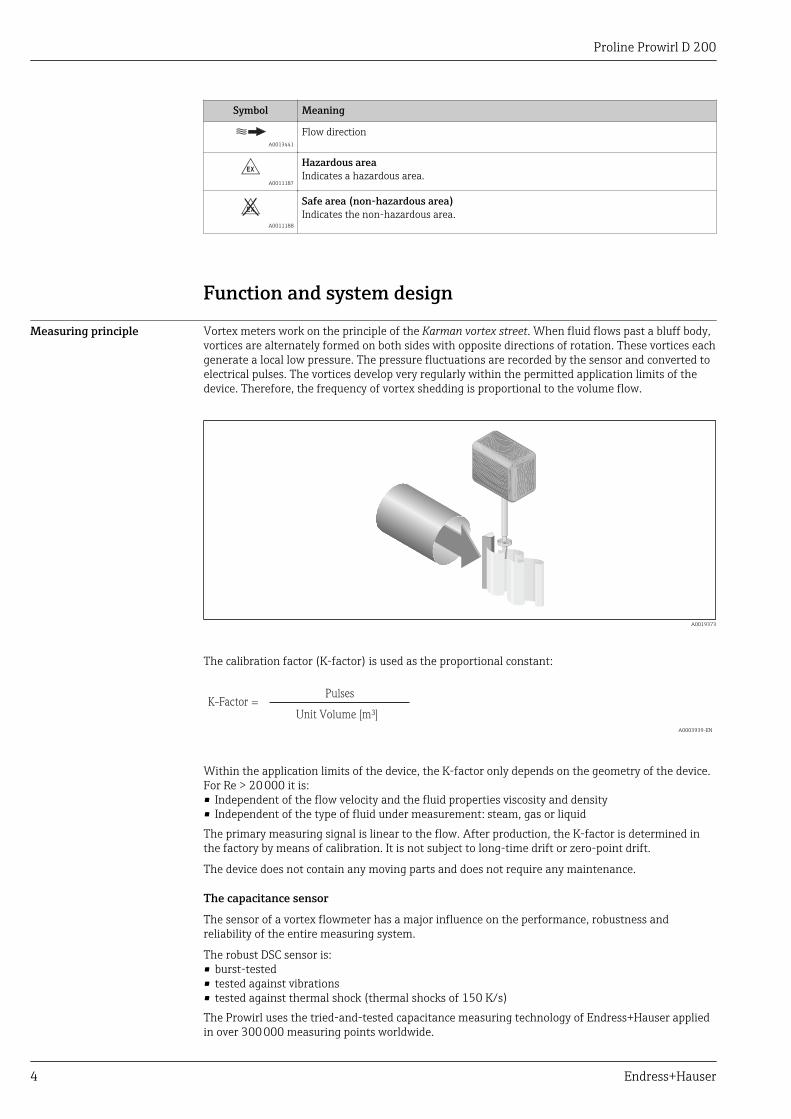
Measuring principle Vortex meters work on the principle of the Karman vortex street. When fluid flows past a bluff body,vortices are alternately formed on both sides with opposite directions of rotation. These vortices eachgenerate a local low pressure. The pressure fluctuations are recorded by the sensor and converted toelectrical pulses. The vortices develop very regularly within the permitted application limits of thedevice. Therefore, the frequency of vortex shedding is proportional to the volume flow.
A0019373
The calibration factor (K-factor) is used as the proportional constant:
K-Factor =Pulses
Unit Volume [m³] A0003939-EN
Within the application limits of the device, the K-factor only depends on the geometry of the device.For Re > 20 000 it is:• Independent of the flow velocity and the fluid properties viscosity and density• Independent of the type of fluid under measurement: steam, gas or liquidThe primary measuring signal is linear to the flow. After production, the K-factor is determined inthe factory by means of calibration. It is not subject to long-time drift or zero-point drift.
The device does not contain any moving parts and does not require any maintenance.
The capacitance sensor
The sensor of a vortex flowmeter has a major influence on the performance, robustness andreliability of the entire measuring system.
The robust DSC sensor is:• burst-tested• tested against vibrations• tested against thermal shock (thermal shocks of 150 K/s)The Prowirl uses the tried-and-tested capacitance measuring technology of Endress+Hauser appliedin over 300 000 measuring points worldwide.
Proline Prowirl D 200
Endress+Hauser 5
The DSC (differential switched capacitance) sensor patented by Endress+Hauser has completemechanical balancing. It only reacts to the measured variable (vortex) and does not react tovibrations. Even in the event of pipe vibrations, the smallest of flows can be reliably measured at lowdensity thanks to the unimpaired sensitivity of the sensor. Thus, the wide turndown is alsomaintained even in the event of harsh operating conditions. Vibrations up to 1 g at least, atfrequencies up to 500 Hz in every axis (X, Y, Z), do not affect the flow measurement. Thanks to itsdesign, the capacitance sensor is also particularly mechanically resistant to temperature shocks andpressure shocks in steam pipelines.
Temperature measurement
Under the "Sensor version" order code the "Mass flow" option is available (→ 5). With thisoption the measuring device can also measure the temperature of the medium.
The temperature is measured via Pt 1000 temperature sensors. These sensors are located in thepaddle of the DSC sensor and are therefore in the direct vicinity of the fluid.
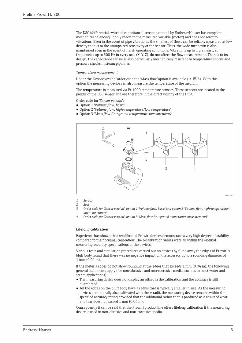
Order code for "Sensor version":• Option 1 "Volume flow, basis"• Option 2 "Volume flow, high-temperature/low temperature"• Option 3 "Mass flow (integrated temperature measurement)"
X
Y
Z
1
2
3 4
A0019730
1 Sensor2 Seal3 Order code for "Sensor version", option 1 "Volume flow, basis" and option 2 "Volume flow, high-temperature/
low-temperature"4 Order code for "Sensor version", option 3 "Mass flow (integrated temperature measurement)"
Lifelong calibration
Experience has shown that recalibrated Prowirl devices demonstrate a very high degree of stabilitycompared to their original calibration: The recalibration values were all within the originalmeasuring accuracy specifications of the devices.
Various tests and simulation procedures carried out on devices by filing away the edges of Prowirl’sbluff body found that there was no negative impact on the accuracy up to a rounding diameter of1 mm (0.04 in).
If the meter’s edges do not show rounding at the edges that exceeds 1 mm (0.04 in), the followinggeneral statements apply (for non-abrasive and non-corrosive media, such as in most water andsteam applications):• The measuring device does not display an offset in the calibration and the accuracy is still
guaranteed.• All the edges on the bluff body have a radius that is typically smaller in size. As the measuring
devices are naturally also calibrated with these radii, the measuring device remains within thespecified accuracy rating provided that the additional radius that is produced as a result of wearand tear does not exceed 1 mm (0.04 in).
Consequently it can be said that the Prowirl product line offers lifelong calibration if the measuringdevice is used in non-abrasive and non-corrosive media.

Proline Prowirl D 200
6 Endress+Hauser
Diagnostic functions
In addition, the device offers extensive diagnostic options, such as tracing fluid and ambienttemperatures, extreme flows etc.
Minimum and maximum values:• Frequency• Temperature• Velocity• Pressure

Proline Prowirl D 200
Endress+Hauser 7
Measuring system The device consists of a transmitter and a sensor.
Two device versions are available:• Compact version - the transmitter and sensor form a mechanical unit.• Remote version – the transmitter and sensor are mounted separately from one another.
Transmitter
Prowirl 200 Device versions and materials:• Compact or remote version, aluminum coated:
Coated aluminum AlSi10Mg• Compact or remote version, stainless:
For maximum corrosion resistance: stainless steel 1.4404 (316L)
Configuration:• Via four-line local display with key operation or via four-line,
illuminated local display with touch control and guided menus ("Make-it-run" wizards) for applications
• Via operating tools (e.g. FieldCare)
A0013471
Sensor
Prowirl D Disc (wafer version):• Nominal diameter range: DN 15 to 150 (½ to 6")• Materials:
Measuring tubes: stainless steel, 1.4408 (CF3M)
A0009922
Input
Measured variable Direct measured variables
Order code for "Sensor version":• Option 1 "Volume flow, basis" and• Option 2 "Volume flow, high-temperature/low temperature":
Volume flowOrder code for "Sensor version":Option 3 "Mass flow (integrated temperature measurement)":– Volume flow– Temperature
Calculated measured variables
Order code for "Sensor version":• Option 1 "Volume flow, basis" and• Option 2 "Volume flow, high-temperature/low temperature":
– In the case of constant process conditions: Mass flow 1) or Corrected volume flow– The totalized values for Volume flow, Mass flow 1), or Corrected volume flow
1) A fixed density must be entered for calculating the mass flow (Setup menu → Advanced setup submenu → External compensation submenu →Fixed density parameter).

Proline Prowirl D 200
8 Endress+Hauser
Order code for "Sensor version":Option 3 "Mass flow (integrated temperature measurement)":– Mass flow– Corrected volume flow– Energy flow– Heat flow difference– Calculated saturated steam pressure
Proline Prowirl D 200
Endress+Hauser 9
Calculation of the measured variables
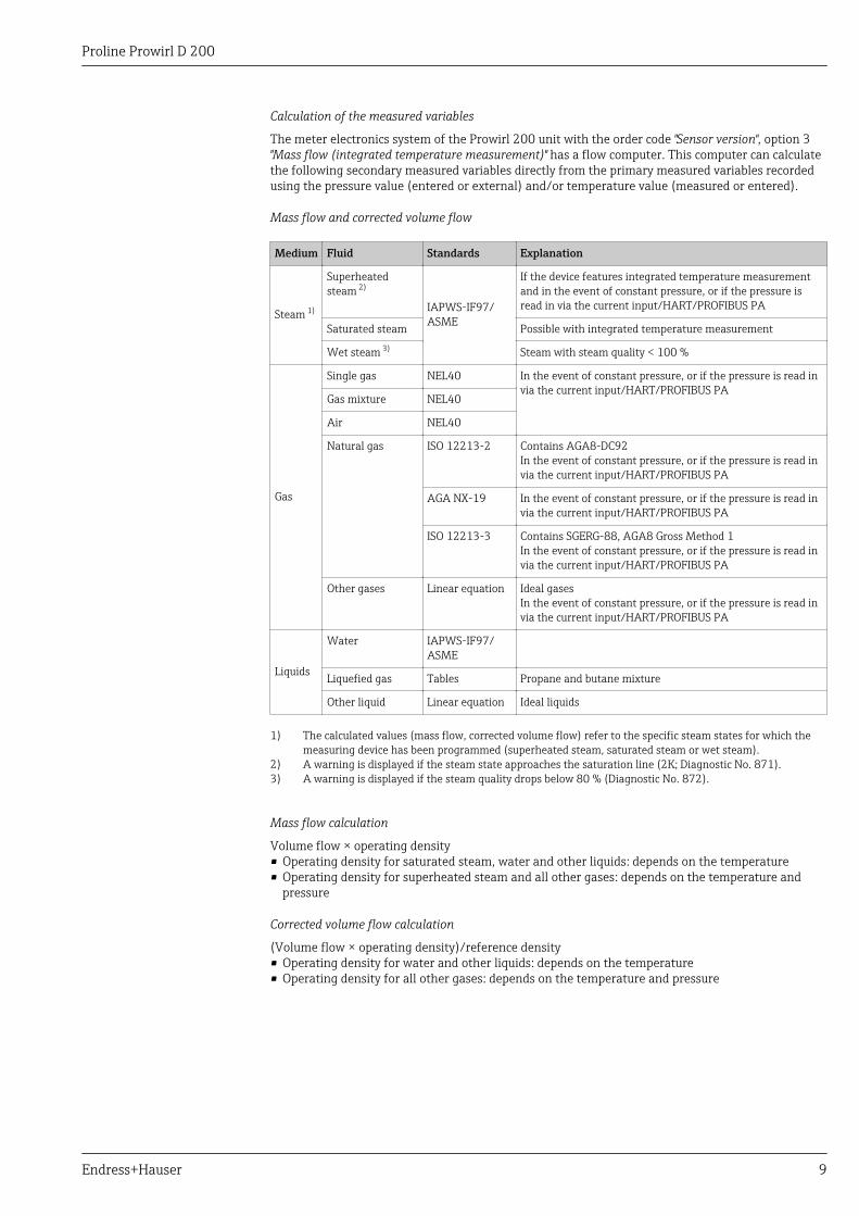
The meter electronics system of the Prowirl 200 unit with the order code "Sensor version", option 3"Mass flow (integrated temperature measurement)" has a flow computer. This computer can calculatethe following secondary measured variables directly from the primary measured variables recordedusing the pressure value (entered or external) and/or temperature value (measured or entered).
Mass flow and corrected volume flow
Medium Fluid Standards Explanation
Steam 1)
Superheatedsteam 2)
IAPWS-IF97/ASME
If the device features integrated temperature measurementand in the event of constant pressure, or if the pressure isread in via the current input/HART/PROFIBUS PA
Saturated steam Possible with integrated temperature measurement
Wet steam 3) Steam with steam quality < 100 %
Gas
Single gas NEL40 In the event of constant pressure, or if the pressure is read invia the current input/HART/PROFIBUS PA
Gas mixture NEL40
Air NEL40
Natural gas ISO 12213-2 Contains AGA8-DC92In the event of constant pressure, or if the pressure is read invia the current input/HART/PROFIBUS PA
AGA NX-19 In the event of constant pressure, or if the pressure is read invia the current input/HART/PROFIBUS PA
ISO 12213-3 Contains SGERG-88, AGA8 Gross Method 1In the event of constant pressure, or if the pressure is read invia the current input/HART/PROFIBUS PA
Other gases Linear equation Ideal gasesIn the event of constant pressure, or if the pressure is read invia the current input/HART/PROFIBUS PA
Liquids
Water IAPWS-IF97/ASME
Liquefied gas Tables Propane and butane mixture
Other liquid Linear equation Ideal liquids
1) The calculated values (mass flow, corrected volume flow) refer to the specific steam states for which themeasuring device has been programmed (superheated steam, saturated steam or wet steam).
2) A warning is displayed if the steam state approaches the saturation line (2K; Diagnostic No. 871).3) A warning is displayed if the steam quality drops below 80 % (Diagnostic No. 872).
Mass flow calculation
Volume flow × operating density• Operating density for saturated steam, water and other liquids: depends on the temperature• Operating density for superheated steam and all other gases: depends on the temperature and
pressure
Corrected volume flow calculation
(Volume flow × operating density)/reference density• Operating density for water and other liquids: depends on the temperature• Operating density for all other gases: depends on the temperature and pressure
Proline Prowirl D 200
10 Endress+Hauser
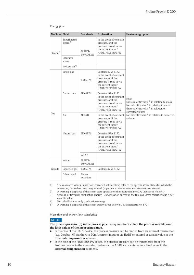
Energy flow
Medium Fluid Standards Explanation Heat/energy option
Steam 1)
Superheatedsteam 2)
IAPWS-IF97/ASME
In the event of constantpressure, or if thepressure is read in viathe current input/HART/PROFIBUS PA
HeatGross calorific value 3) in relation to massNet calorific value 4) in relation to massGross calorific value 3) in relation tocorrected volumeNet calorific value 4) in relation to correctedvolume
Saturatedsteam
Wet steam 5)
Gas
Single gas
ISO 6976
Contains GPA 2172In the event of constantpressure, or if thepressure is read in viathe current input/HART/PROFIBUS PA
Gas mixture ISO 6976 Contains GPA 2172In the event of constantpressure, or if thepressure is read in viathe current input/HART/PROFIBUS PA
Air NEL40 In the event of constantpressure, or if thepressure is read in viathe current input/HART/PROFIBUS PA
Natural gas ISO 6976 Contains GPA 2172In the event of constantpressure, or if thepressure is read in viathe current input/HART/PROFIBUS PA
AGA 5
Liquids
Water IAPWS-IF97/ASME
Liquefied gas ISO 6976 Contains GPA 2172
Other liquid Linearequation
1) The calculated values (mass flow, corrected volume flow) refer to the specific steam states for which themeasuring device has been programmed (superheated steam, saturated steam or wet steam).
2) A warning is displayed if the steam state approaches the saturation line (2K; Diagnostic No. 871).3) Gross calorific value: combustion energy + condensation energy of the flue gas (gross calorific value > net
calorific value)4) Net calorific value: only combustion energy5) A warning is displayed if the steam quality drops below 80 % (Diagnostic No. 872).
Mass flow and energy flow calculation
NOTICEThe process pressure (p) in the process pipe is required to calculate the process variables andthe limit values of the measuring range.‣ In the case of the HART device, the process pressure can be read in from an external transmitter
(e.g. Cerabar-M) via the 4 to 20mA current input or via HART or entered as a fixed value in theExternal compensation submenu.
‣ In the case of the PROFIBUS PA device, the process pressure can be transmitted from theProfibus master to the measuring device via the AO Block or entered as a fixed value in theExternal compensation submenu.

Proline Prowirl D 200
Endress+Hauser 11
The calculation is performed based on the following factors:• Assuming superheated steam conditions the measuring device calculates until the saturation point
is reached. At 2 K above saturation, warning 871 "Approaching saturation line" is triggered. Thewarning can be redefined as an alarm or can also be disabled .
• If the temperature continues to drop, assuming saturated steam conditions the measuring devicecontinues measuring up to a temperature of 0 °C (+32 °F). If pressure is the preferred measuredvariable, the Saturated steam option must be selected in the Select steam type parameter andthe Pressure option must be selected in the Saturated steam calculation mode parameter(Expert menu → Sensor submenu → Measurement mode submenu → Saturated steamcalculation mode parameter).
Detailed information on external compensation is provided in the Operating Instructions for thedevice
Calculated value
The unit calculates the mass flow, heat flow, energy flow, density and specific enthalpy from themeasured volume flow and the measured temperature and/or the pressure based on internationalstandard IAPWS-IF97 (ASME steam data).
Formulae for calculation:• Mass flow: m = q ⋅ ρ (T, p)• Heat quantity: E = q ⋅ ρ (T, p) ⋅ hD (T, p)m = Mass flow
E = Heat quantity
q = Volume flow (measured)
hD = Specific enthalpy
T = Operating temperature (measured)
p = Process pressure
ρ = Density 2)
Pre-programmed gases
The following gases are pre-programmed in the flow computer:
Hydrogen 1) Helium 4 Neon Argon
Krypton Xenon Nitrogen Oxygen
Chlorine Ammonia Carbon monoxide 1) Carbon dioxide
Sulfur dioxide Hydrogen sulfide 1) Hydrogen chloride Methane 1)
Ethane 1) Propane 1) Butane 1) Ethylene (ethene) 1)
Vinyl chloride Mixtures of up to 8 components of these gases 1)
1) The energy flow is calculated as per ISO 6976 (contains GPA 2172) or AGA5 - in relation to the netcalorific value or gross calorific value .
Energy flow calculation
Volume flow × operating density × specific enthalpy• Operating density for saturated steam and water: depends on the temperature• Operating density for superheated steam, natural gas ISO 6976 (contains GPA 2172), natural gas
AGA5: depends on the temperature and pressure
Heat flow difference
• Between saturated steam upstream from a heat exchanger and condensate downstream from theheat exchanger (second temperature read in via current input/HART/PROFIBUS PA) in accordancewith IAPWS-IF97/ASME (→ 41).
• Between warm water and cold water (second temperature read in via current input/HART/PROFIBUS PA) in accordance with IAPWS-IF97/ASME.
2) From steam data as per IAPWS-IF97 (ASME), for the measured temperature and the specified pressure
Proline Prowirl D 200
12 Endress+Hauser
Vapor pressure and steam temperature
The measuring device can perform the following in saturated steam measurements between the feedline and return line of any heating liquid (second temperature read in via current input/HART/PROFIBUS PA and Cp value entered):• Calculate the saturation pressure of the steam from the measured temperature and output the
value in accordance with IAPWS-IF97/ASME.• Calculate the saturation temperature of the steam from the specified pressure and output the
value in accordance with IAPWS-IF97/ASME.
Saturated steam alarm
In applications involving the measurement of superheated steam, the measuring device can trigger asaturated steam alarm when the value approaches the saturation curve.
Total mass flow and condensate mass flow
• Using the steam quality entered, the measuring device can calculate the total mass flow andoutput it in the form of the proportion of gas and liquid.
• Using the steam quality entered, the measuring device can calculate the condensate mass flow andoutput it in the form of the proportion of liquid.

Proline Prowirl D 200
Endress+Hauser 13
Measuring range The measuring range depends on the fluid and nominal diameter.
Lower range value
Depends on the density and the Reynolds number (Remin = 5 000, Relinear = 20 000). The Reynoldsnumber is dimensionless and indicates the ratio of the inertia force of a fluid to its viscous force. It isused to characterize the flow. The Reynolds number is calculated as follows:
Re =4 · Q · m³[m³/s] [kg/ ]ρ
di [m] · µπ π · [Pa·s]Re =
4 · Q · ³[ft³/s] [lb/ft ]ρ
di [ft] · µπ · [0.001 cP]
A0003794
Re = Reynolds number; Q = flow; di = internal diameter; µ = dynamic viscosity, ρ = density
vDN ½...6" → =min.
4.92
ρ [lb/ft³]
[ft/s]
vDN 15...150 → =min.
6
ρ [kg/m³]
[m/s]
A0020557
Upper range value
Liquids:The upper range value must be calculated as follows:vmax = 9 m/s (30 ft/s) and vmax = 350/√ρ m/s (130/√ρ ft/s)
‣ Use the lower value.
Gas/steam:
Nominal diameter vmax
Standard device: DN 15 (½") 46 m/s (151 ft/s) and 350/√ρ m/s (130/√ρ ft/s)(Use the lower value.)
Standard device: DN 25 (1"), DN 40 (1½") 75 m/s (246 ft/s) and 350/√ρ m/s (130/√ρ ft/s)(Use the lower value.)
Standard device: DN 50 to 150 (2 to 8") 120 m/s (394 ft/s) and 350/√ρ m/s (130/√ρ ft/s)(Use the lower value.)Calibrated range: up to 75 m/s (246 ft/s)
For information about the Applicator (→ 78)
Operable flow range Up to 45: 1 (ratio between lower and upper range value)
Input signal External measured values
To increase the accuracy of certain measured variables or to calculate the corrected volume flow, theautomation system can continuously write different measured values to the measuring device:• Operating pressure to increase accuracy (Endress+Hauser recommends the use of a pressure
measuring device for absolute pressure, e.g. Cerabar M or Cerabar S)• Medium temperature to increase accuracy (e.g. iTEMP)• Reference density for calculating the corrected volume flow
• Various pressure transmitters can be ordered from Endress+Hauser: see "Accessories" section(→ 78)
• Please comply with the special mounting instructions when using pressure transmitters(→ 41)
Proline Prowirl D 200
14 Endress+Hauser
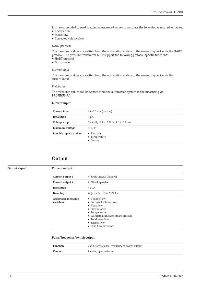
It is recommended to read in external measured values to calculate the following measured variables:• Energy flow• Mass flow• Corrected volume flow
HART protocol
The measured values are written from the automation system to the measuring device via the HARTprotocol. The pressure transmitter must support the following protocol-specific functions:• HART protocol• Burst mode
Current input
The measured values are written from the automation system to the measuring device via thecurrent input.
Fieldbuses
The measured values can be written from the automation system to the measuring via:PROFIBUS-PA
Current input
Current input 4 to 20 mA (passive)
Resolution 1 µA
Voltage drop Typically: 2.2 to 3 V for 3.6 to 22 mA
Maximum voltage ≤ 35 V
Possible input variables • Pressure• Temperature• Density
Output
Output signal Current output
Current output 1 4-20 mA HART (passive)
Current output 2 4-20 mA (passive)
Resolution <1 µA
Damping Adjustable: 0.0 to 999.9 s
Assignable measuredvariables
• Volume flow• Corrected volume flow• Mass flow• Flow velocity• Temperature• Calculated saturated steam pressure• Total mass flow• Energy flow• Heat flow difference
Pulse/frequency/switch output
Function Can be set to pulse, frequency or switch output
Version Passive, open collector

Proline Prowirl D 200
Endress+Hauser 15
Maximum input values • DC 35 V• 50 mA
For information on the Ex connection values (→ 17)
Voltage drop • For ≤2 mA: 2 V• For 10 mA: 8 V
Residual current ≤0.05 mA
Pulse output
Pulse width Adjustable: 5 to 2 000 ms
Maximum pulse rate 100 Impulse/s
Pulse value Adjustable
Assignable measuredvariables
• Total volume flow• Total corrected volume flow• Total mass flow• Total energy flow• Total heat flow difference
Frequency output
Output frequency Adjustable: 0 to 1 000 Hz
Damping Adjustable: 0 to 999 s
Pulse/pause ratio 1:1
Assignable measuredvariables
• Volume flow• Corrected volume flow• Mass flow• Flow velocity• Temperature• Calculated saturated steam pressure• Steam quality• Total mass flow• Energy flow• Heat flow difference
Switch output
Switching behavior Binary, conductive or non-conductive
Switching delay Adjustable: 0 to 100 s
Number of switchingcycles
Unlimited
Assignable functions • Off• On• Diagnostic behavior• Limit value
– Volume flow– Corrected volume flow– Mass flow– Flow velocity– Temperature– Calculated saturated steam pressure– Steam quality– Total mass flow– Energy flow– Heat flow difference– Reynolds number– Totalizer 1-3
• Status• Status of low flow cut off

Proline Prowirl D 200
16 Endress+Hauser
PROFIBUS PA
Signal encoding Manchester Bus Powered (MBP)
Data transfer 31.25 KBit/s, Voltage mode
Signal on alarm Depending on the interface, failure information is displayed as follows:
Current output
HART
Device diagnostics Device condition can be read out via HART Command 48
Pulse/frequency/switch output
Pulse output
Failure mode No pulses
Frequency output
Failure mode Choose from:• Actual value• Defined value: 0 to 1 250 Hz• 0 Hz
Switch output
Failure mode Choose from:• Current status• Open• Closed
PROFIBUS PA
Status and alarmmessages
Diagnostics in accordance with PROFIBUS PA Profile 3.02
Error current FDE (FaultDisconnection Electronic)
0 mA
Local display
Plain text display With information on cause and remedial measures
Backlight Additionally for device version with SD03 local display: red lighting indicates adevice error.
Status signal as per NAMUR recommendation NE 107
Operating tool
• Via digital communication:– HART protocol– PROFIBUS PA
• Via service interface
Plain text display With information on cause and remedial measures
Additional information on remote operation (→ 69)

Proline Prowirl D 200
Endress+Hauser 17
Load Load for current output: 0 to 500 Ω, depending on the external supply voltage of the power supplyunit
Calculation of the maximum load
Depending on the supply voltage of the power supply unit (US), the maximum load (RB) includingline resistance must be observed to ensure adequate terminal voltage at the device. In doing so,observe the minimum terminal voltage (→ 25)
• RB ≤ (US - Uterm. min) :0.022 A• RB ≤500 Ω
0
100
200
300
400
500
12 14 16 18 20 22 24 26 28 U [V]s
R [ ]b W 1.1 1.21
30 32 34 3635
A0020417
1 Load for a compact version without local operation
1 Operating range1.1 For order code for "Output", option A "4-20 mA HART"/option B "4-20 mA HART, pulse/frequency/switch
output" with Ex i and option C "4-20 mA HART, 4-20 mA"1.2 For order code for "Output", option A "4-20 mA HART"/option B "4-20 mA HART, pulse/frequency/switch
output" with non-Ex and Ex d
Sample calculationSupply voltage of the supply unit:– US = 19 V– Uterm. min = 12 V (measuring device) + 1 V (local operation without lighting) = 13 VMaximum load: RB≤ (19 V - 13 V) :0.022 A = 273 Ω
The minimum terminal voltage (Uterm. min) increases if local operation is used (→ 26).
Ex connection data Safety-related values
Ex d type of protection
Order code for "Output" Output type Safety-related values
Option A 4-20mA HART Unom = DC 35 VUmax = 250 V
Option B 4-20mA HART Unom = DC 35 VUmax = 250 V
Pulse/frequency/switch output Unom = DC 35 VUmax = 250 VPmax = 1 W 1)
Option C 4-20mA HART Unom = DC 30 VUmax = 250 V4-20mA
Option D 4-20mA HART Unom = DC 35 VUmax = 250 V

Proline Prowirl D 200
18 Endress+Hauser
Order code for "Output" Output type Safety-related values
Pulse/frequency/switch output Unom = DC 35 VUmax = 250 VPmax = 1 W 1)
4 to 20 mA current input Unom = DC 35 VUmax = 250 V
Option G PROFIBUS PA Unom = DC 32 VUmax = 250 VPmax = 0.88 W
Pulse/frequency/switch output Unom = DC 35 VUmax = 250 VPmax = 1 W 1)
1) Internal circuit limited by Ri = 760.5 Ω
Ex nA type of protection
Order code for "Output" Output type Safety-related values
Option A 4-20mA HART Unom = DC 35 VUmax = 250 V
Option B 4-20mA HART Unom = DC 35 VUmax = 250 V
Pulse/frequency/switch output Unom = DC 35 VUmax = 250 VPmax = 1 W 1)
Option C 4-20mA HART Unom = DC 30 VUmax = 250 V4-20mA
Option D 4-20mA HART Unom = DC 35 VUmax = 250 V
Pulse/frequency/switch output Unom = DC 35 VUmax = 250 VPmax = 1 W
4 to 20 mA current input Unom = DC 35 VUmax = 250 V
Option G PROFIBUS PA Unom = DC 32 VUmax = 250 VPmax = 0.88 W
Pulse/frequency/switch output Unom = DC 35 VUmax = 250 VPmax = 1 W
1) Internal circuit limited by Ri = 760.5 Ω
Type of protection XP
Order code for "Output" Output type Safety-related values
Option A 4-20mA HART Unom = DC 35 VUmax = 250 V
Option B 4-20mA HART Unom = DC 35 VUmax = 250 V
Pulse/frequency/switch output Unom = DC 35 VUmax = 250 VPmax = 1 W 1)
Option C 4-20mA HART Unom = DC 30 VUmax = 250 V4-20mA

Proline Prowirl D 200
Endress+Hauser 19
Order code for "Output" Output type Safety-related values
Option D 4-20mA HART Unom = DC 35 VUmax = 250 V
Pulse/frequency/switch output Unom = DC 35 VUmax = 250 VPmax = 1 W
4 to 20 mA current input Unom = DC 35 VUmax = 250 V
Option G PROFIBUS PA Unom = DC 32 VUmax = 250 VPmax = 0.88 W
Pulse/frequency/switch output Unom = DC 35 VUmax = 250 VPmax = 1 W
1) Internal circuit limited by Ri = 760.5 Ω
Intrinsically safe values
Type of protection Ex ia
Order code for "Output" Output type Intrinsically safe values
Option A 4-20mA HART Ui = DC 30 VIi = 300 mAPi = 1 WLi = 0 μHCi = 5 nF
Option B 4-20mA HART Ui = DC 30 VIi = 300 mAPi = 1 WLi = 0 μHCi = 5 nF
Pulse/frequency/switch output Ui = DC 30 VIi = 300 mAPi = 1 WLi = 0 μHCi = 6 nF
Option C 4-20mA HART Ui = DC 30 VIi = 300 mAPi = 1 WLi = 0 μHCi = 30 nF
4-20mA
Option D 4-20mA HART Ui = DC 30 VIi = 300 mAPi = 1 WLi = 0 μHCi = 5 nF
Pulse/frequency/switch output Ui = DC 30 VIi = 300 mAPi = 1 WLi = 0 μHCi = 6 nF
Proline Prowirl D 200
20 Endress+Hauser
Order code for "Output" Output type Intrinsically safe values
4 to 20 mA current input Ui = DC 30 VIi = 300 mAPi = 1 WLi = 0 μHCi = 5 nF
Option G PROFIBUS PA STANDARDUi = 30 Vli = 300 mAPi = 1.2 WLi = 10 µHCi = 5 nF
FISCOUi = 17.5 Vli = 550 mAPi = 5.5 WLi = 10 µHCi = 5 nF
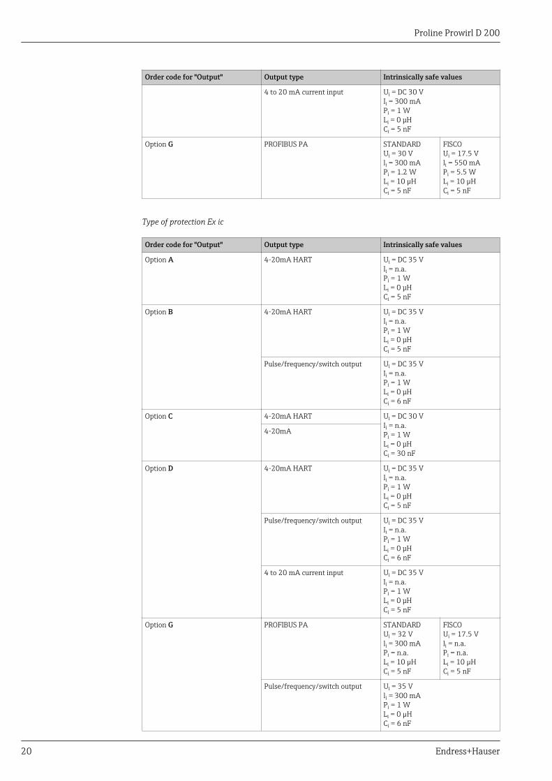
Type of protection Ex ic
Order code for "Output" Output type Intrinsically safe values
Option A 4-20mA HART Ui = DC 35 VIi = n.a.Pi = 1 WLi = 0 μHCi = 5 nF
Option B 4-20mA HART Ui = DC 35 VIi = n.a.Pi = 1 WLi = 0 μHCi = 5 nF
Pulse/frequency/switch output Ui = DC 35 VIi = n.a.Pi = 1 WLi = 0 μHCi = 6 nF
Option C 4-20mA HART Ui = DC 30 VIi = n.a.Pi = 1 WLi = 0 μHCi = 30 nF
4-20mA
Option D 4-20mA HART Ui = DC 35 VIi = n.a.Pi = 1 WLi = 0 μHCi = 5 nF
Pulse/frequency/switch output Ui = DC 35 VIi = n.a.Pi = 1 WLi = 0 μHCi = 6 nF
4 to 20 mA current input Ui = DC 35 VIi = n.a.Pi = 1 WLi = 0 μHCi = 5 nF
Option G PROFIBUS PA STANDARDUi = 32 Vli = 300 mAPi = n.a.Li = 10 µHCi = 5 nF
FISCOUi = 17.5 Vli = n.a.Pi = n.a.Li = 10 µHCi = 5 nF
Pulse/frequency/switch output Ui = 35 Vli = 300 mAPi = 1 WLi = 0 µHCi = 6 nF
Proline Prowirl D 200
Endress+Hauser 21
IS type of protection
Order code for "Output" Output type Intrinsically safe values
Option A 4-20mA HART Ui = DC 30 VIi = 300 mAPi = 1 WLi = 0 μHCi = 5 nF
Option B 4-20mA HART Ui = DC 30 VIi = 300 mAPi = 1 WLi = 0 μHCi = 5 nF
Pulse/frequency/switch output Ui = DC 30 VIi = 300 mAPi = 1 WLi = 0 μHCi = 6 nF
Option C 4-20mA HART Ui = DC 30 VIi = 300 mAPi = 1 WLi = 0 μHCi = 30 nF
4-20mA
Option D 4-20mA HART Ui = DC 30 VIi = 300 mAPi = 1 WLi = 0 μHCi = 5 nF
Pulse/frequency/switch output Ui = DC 30 VIi = 300 mAPi = 1 WLi = 0 μHCi = 6 nF
4 to 20 mA current input Ui = DC 30 VIi = 300 mAPi = 1 WLi = 0 μHCi = 5 nF
Option G PROFIBUS PA STANDARDUi = 30 Vli = 300 mAPi = 1.2 WLi = 10 µHCi = 5 nF
FISCOUi = 17.5 Vli = 550 mAPi = 5.5 WLi = 10 µHCi = 5 nF
Pulse/frequency/switch output Ui = 30 Vli = 300 mAPi = 1 WLi = 0 µHCi = 6 nF
Low flow cut off The switch points for low flow cut off are user-selectable.
Galvanic isolation All outputs are galvanically isolated from one another.
Protocol-specific data HART
Manufacturer ID 0x11
Device type ID 0x38
HART protocol revision 7

Proline Prowirl D 200
22 Endress+Hauser
Device description files(DTM, DD)
Information and files under:www.endress.com
HART load • Min. 250 Ω• Max. 500 Ω
Dynamic variables The measured variables can be freely assigned to the dynamic variables.
Measured variables for PV (primary dynamic variable)• Volume flow• Corrected volume flow• Mass flow• Flow velocity• Temperature• Calculated saturated steam pressure• Steam quality• Total mass flow• Energy flow• Heat flow difference
Measured variables for SV, TV, QV (secondary, tertiary and quaternarydynamic variable)• Volume flow• Corrected volume flow• Mass flow• Flow velocity• Temperature• Calculated saturated steam pressure• Steam quality• Total mass flow• Energy flow• Heat flow difference• Condensate mass flow• Reynolds number• Totalizer 1• Totalizer 2• Totalizer 3• HART input
Device variables Readout the device variables: HART command 9The device variables are fixed assigned.
Maximum 8 device variables can be transmitted:• 0 = Volume flow• 1 = Corrected volume flow• 2 = Mass flow• 3 = Flow velocity• 4 = Temperature• 5 = Calculated saturated steam pressure• 6 = Steam quality• 7 = Total mass flow• 8 = Energy flow• 9 = Heat flow difference• 10 = Condensate mass flow• 11 = Reynolds number• 12 = Totalizer value 1• 13 = Totalizer value 2• 14 = Totalizer value 3
PROFIBUS PA
Manufacturer ID 0x11
Ident number 0x1564
Profile version 3.02
Device description files (GSD,DTM, DD)
Information and files under:• www.endress.com• www.profibus.org

Proline Prowirl D 200
Endress+Hauser 23
Output values(from measuring device toautomation system)
Analog input 1 to 4• Mass flow• Volume flow• Corrected volume flow• Density• Reference density• Temperature
Digital input 1 to 2• Status• Low flow cut off• Switch output
Totalizer 1 to 3• Mass flow• Volume flow• Corrected volume flow
Input values(from automation system tomeasuring device)
Analog outputExternal pressure, gage pressure, density, temperature or second temperature(for delta heat measurement)
Digital output 1 to 3 (fixed assignment)• Digital output 1: switch positive zero return on/off• Digital output 2: switch switch output on/off• Digital output 3: Start verification
Totalizer 1 to 3• Totalize• Reset and hold• Preset and hold
Supported functions • Identification & MaintenanceSimplest device identification on the part of the control system andnameplate
• PROFIBUS upload/downloadReading and writing parameters is up to ten times faster with PROFIBUSupload/download
• Condensed statusSimplest and self-explanatory diagnostic information by categorizingdiagnostic messages that occur
Configuration of the deviceaddress
• DIP switches on the I/O electronics module• Local display• Via operating tools (e.g. FieldCare)

Proline Prowirl D 200
24 Endress+Hauser
Power supply
Terminal assignment Transmitter
Connection versions
–
4
+
1
–
2
+
3
12 4
–
6
+
5
3
A0020738
+
1
–
2
–
4
+
3
–
6
+
5
3 12 4
A0020739
Maximum number of terminalsTerminals 1 to 6:Without integrated overvoltage protection
Maximum number of terminals for order code for"Accessory mounted", option NA "Overvoltageprotection"• Terminals 1 to 4:
With integrated overvoltage protection• Terminals 5 to 6:
Without integrated overvoltage protection
1234
Output 1 (passive): supply voltage and signal transmissionOutput 2 (passive): supply voltage and signal transmissionInput (passive): supply voltage and signal transmissionGround terminal for cable shield
Order code for "Output" Terminal numbers
Output 1 Output 2 Input
1 (+) 2 (-) 3 (+) 4 (-) 5 (+) 6 (-)
Option A 4-20 mA HART (passive) - -
Option B 1) 4-20 mA HART (passive) Pulse/frequency/switchoutput (passive)
-
Option C 1) 4-20 mA HART (passive) 4-20 mA (passive) -
Option D 1) 2) 4-20 mA HART (passive) Pulse/frequency/switchoutput (passive)
4-20 mA current input(passive)
Option G 1) 3) PROFIBUS PA Pulse/frequency/switchoutput (passive)
-
1) Output 1 must always be used; output 2 is optional.2) The integrated overvoltage protection is not used with option D: Terminals 5 and 6 (current input) are not
protected against overvoltage.3) PROFIBUS PA with integrated reverse polarity protection.
Remote version
In the case of the remote version, the sensor and transmitter are mounted separately from oneanother and connected by a connecting cable. The sensor is connected via the connection housingwhile the transmitter is connected via the connection compartment of the wall holder unit.
The way the transmitter wall holder is connected depends on the measuring device approvaland the version of the connecting cable used.
Connection is only possible via terminals:• For approvals Ex n, Ex tb and cCSAus Div. 1• If a reinforced connecting cable is usedThe connection is via an M12 connector:• For all other approvals• If the standard connecting cable is usedConnection to the connection housing of the sensor is always via terminals.

Proline Prowirl D 200
Endress+Hauser 25
41 2 3
1
2
+ –
A0019335
2 Terminals for connection compartment in the transmitter wall holder and the sensor connection housing
1 Terminals for connecting cable2 Grounding via the cable strain relief
Terminal number Assignment Cable colorConnecting cable
1 Supply voltage Brown
2 Grounding White
3 RS485 (+) Yellow
4 RS485 (–) Green
Pin assignment, device plug PROFIBUS PA
Device plug for signal transmission (device side)
1
2
4
3
A0019021
Pin Assignment Coding Plug/socket
1 + PROFIBUS PA + A Plug
2 Grounding
3 - PROFIBUS PA –
4 Not assigned
Supply voltage Transmitter
An external power supply is required for each output.
Supply voltage for a compact version without a local display 1)
Order code for "Output" Minimumterminal voltage 2)
Maximumterminal voltage
Option A: 4-20 mA HART ≥DC 12 V DC 35 V
Option B: 4-20 mA HART, pulse/frequency/switch output ≥DC 12 V DC 35 V
Option C: 4-20 mA HART, 4-20 mA ≥DC 12 V DC 30 V
Option D: 4-20 mA HART, pulse/frequency/switch output, 4-20 mA currentinput 3)
≥DC 12 V DC 35 V
Option G: PROFIBUS PA, pulse/frequency/switch output ≥DC 9 V DC 32 V
1) In event of external supply voltage of the power supply unit with load2) The minimum terminal voltage increases if local operation is used: see the following table3) Voltage drop 2.2 to 3 V for 3.59 to 22 mA
Proline Prowirl D 200
26 Endress+Hauser
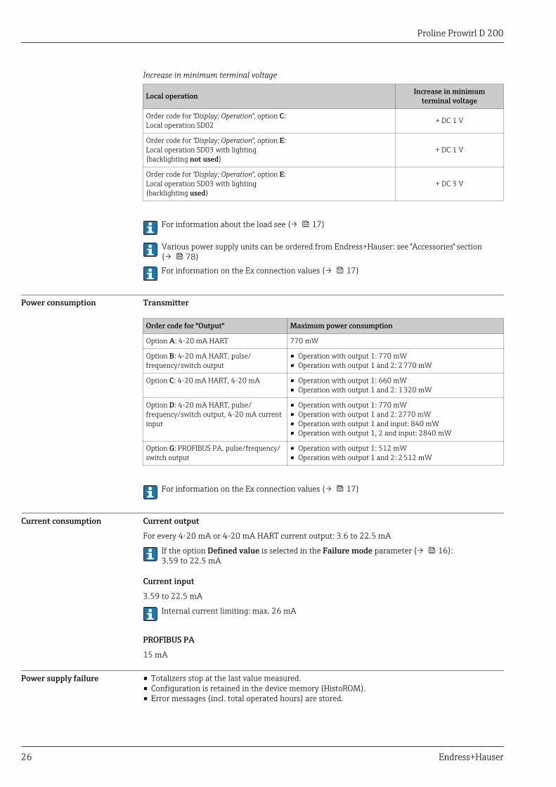
Increase in minimum terminal voltage
Local operation Increase in minimumterminal voltage
Order code for "Display; Operation", option C:Local operation SD02 + DC 1 V
Order code for "Display; Operation", option E:Local operation SD03 with lighting(backlighting not used)
+ DC 1 V
Order code for "Display; Operation", option E:Local operation SD03 with lighting(backlighting used)
+ DC 3 V
For information about the load see (→ 17)
Various power supply units can be ordered from Endress+Hauser: see "Accessories" section(→ 78)For information on the Ex connection values (→ 17)
Power consumption Transmitter
Order code for "Output" Maximum power consumption
Option A: 4-20 mA HART 770 mW
Option B: 4-20 mA HART, pulse/frequency/switch output
• Operation with output 1: 770 mW• Operation with output 1 and 2: 2 770 mW
Option C: 4-20 mA HART, 4-20 mA • Operation with output 1: 660 mW• Operation with output 1 and 2: 1 320 mW
Option D: 4-20 mA HART, pulse/frequency/switch output, 4-20 mA currentinput
• Operation with output 1: 770 mW• Operation with output 1 and 2: 2770 mW• Operation with output 1 and input: 840 mW• Operation with output 1, 2 and input: 2840 mW
Option G: PROFIBUS PA, pulse/frequency/switch output
• Operation with output 1: 512 mW• Operation with output 1 and 2: 2 512 mW
For information on the Ex connection values (→ 17)
Current consumption Current output
For every 4-20 mA or 4-20 mA HART current output: 3.6 to 22.5 mA
If the option Defined value is selected in the Failure mode parameter (→ 16):3.59 to 22.5 mA
Current input
3.59 to 22.5 mA
Internal current limiting: max. 26 mA
PROFIBUS PA
15 mA
Power supply failure • Totalizers stop at the last value measured.• Configuration is retained in the device memory (HistoROM).• Error messages (incl. total operated hours) are stored.

Proline Prowirl D 200
Endress+Hauser 27
Electrical connection Connecting the transmitter
1
1
A0020740
1 Cable entries for inputs/outputs
Remote version connection
Connecting cable
31
2 2
A0019727
3 Connecting cable connection
1 Wall holder with connection compartment (transmitter)2 Connecting cable3 Sensor connection housing
The way the transmitter wall holder is connected depends on the measuring device approvaland the version of the connecting cable used.
Connection is only possible via terminals:• For approvals Ex n, Ex tb and cCSAus Div. 1• If a reinforced connecting cable is usedThe connection is via an M12 connector:• For all other approvals• If the standard connecting cable is usedConnection to the connection housing of the sensor is always via terminals.

Proline Prowirl D 200
28 Endress+Hauser
Connection examples
Current output 4-20 mA HART
2 4
4...20 mA
5 631
+
-7
+
-
A0015511
4 Connection example for 4-20 mA HART current output (passive)
1 Automation system with current input (e.g. PLC)2 Active barrier for power supply (e.g. RN221N) (→ 31)3 Cable shield, observe cable specifications (→ 31)4 Resistor for HART communication (≥ 250 Ω): observe maximum load (→ 17)5 Connection for HART operating devices (→ 69)6 Analog display unit: observe maximum load (→ 17)7 Transmitter
Current output 4-20 mA
2
4...20 mA
31
+
-4
+
–
+
-
A0015512
5 Connection example for 4-20 mA current output (passive)
1 Automation system with current input (e.g. PLC)2 Active barrier for power supply (e.g. RN221N) (→ 25)3 Analog display unit: observe maximum load (→ 17)4 Transmitter

Proline Prowirl D 200
Endress+Hauser 29
Pulse/frequency output
1
+
_
12345
2
+
–
+–
3
A0016801
6 Connection example for pulse/frequency output (passive)
1 Automation system with pulse/frequency input (e.g. PLC)2 Power supply3 Transmitter: observe input values (→ 14)
Switch output
1
+_
+
_
2
+
_ 3
A0016802
7 Connection example for switch output (passive)
1 Automation system with switch input (e.g. PLC)2 Power supply3 Transmitter: observe input values (→ 14)

Proline Prowirl D 200
30 Endress+Hauser
PROFIBUS-PA
21 3
+-
+-
+-
4
5
5
78
6 6
6
6
6
6
. -
A0019004
8 Connection example for PROFIBUS-PA
1 Control system (e.g. PLC)2 Segment coupler PROFIBUS DP/PA3 Cable shield4 T-box5 Measuring device6 Local grounding7 Bus terminator8 Potential matching line
Current input
1
+
-3
+
-
2
A0020741
9 Connection example for 4-20 mA current input
1 Power supply2 External measuring device (for reading in pressure or temperature, for instance)3 Transmitter: observe input values (→ 14)
Proline Prowirl D 200
Endress+Hauser 31
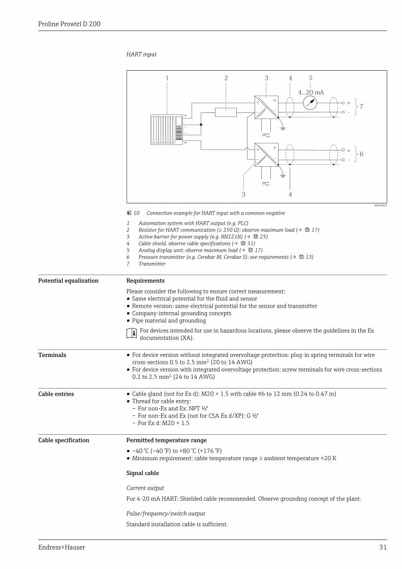
HART input
3
4...20 mA
51
+
-
3
6
+
–
+
+
–
+
–
+
–
+
–
–
2 4
4
7
+
-
A0016029
10 Connection example for HART input with a common negative
1 Automation system with HART output (e.g. PLC)2 Resistor for HART communication (≥ 250 Ω): observe maximum load (→ 17)3 Active barrier for power supply (e.g. RN221N) (→ 25)4 Cable shield, observe cable specifications (→ 31)5 Analog display unit: observe maximum load (→ 17)6 Pressure transmitter (e.g. Cerabar M, Cerabar S): see requirements (→ 13)7 Transmitter
Potential equalization Requirements
Please consider the following to ensure correct measurement:• Same electrical potential for the fluid and sensor• Remote version: same electrical potential for the sensor and transmitter• Company-internal grounding concepts• Pipe material and grounding
For devices intended for use in hazardous locations, please observe the guidelines in the Exdocumentation (XA).
Terminals • For device version without integrated overvoltage protection: plug-in spring terminals for wirecross-sections 0.5 to 2.5 mm2 (20 to 14 AWG)
• For device version with integrated overvoltage protection: screw terminals for wire cross-sections0.2 to 2.5 mm2 (24 to 14 AWG)
Cable entries • Cable gland (not for Ex d): M20 × 1.5 with cable 6 to 12 mm (0.24 to 0.47 in)• Thread for cable entry:
– For non-Ex and Ex: NPT ½"– For non-Ex and Ex (not for CSA Ex d/XP): G ½"– For Ex d: M20 × 1.5
Cable specification Permitted temperature range
• –40 °C (–40 °F) to +80 °C (+176 °F)• Minimum requirement: cable temperature range ≥ ambient temperature +20 K
Signal cable
Current output
For 4-20 mA HART: Shielded cable recommended. Observe grounding concept of the plant.
Pulse/frequency/switch output
Standard installation cable is sufficient.

Proline Prowirl D 200
32 Endress+Hauser
Current input
Standard installation cable is sufficient.
PROFIBUS PA
Twisted, shielded two-wire cable. Cable type A is recommended.
For further information on planning and installing PROFIBUS PA networks see:
• Operating Instructions "PROFIBUS DP/PA: Guidelines for planning and commissioning"(BA00034S)
• PNO Directive 2.092 "PROFIBUS PA User and Installation Guideline"• IEC 61158-2 (MBP)
Connecting cable for remote version
Connecting cable (standard)
Standard cable 4 × 2 × 0.34 mm2 (22 AWG) PVC cable with common shield (4 pairs, pair-stranded)
Flame resistance According to DIN EN 60332-1-2
Oil-resistance According to DIN EN 60811-2-1
Shielding Galvanized copper-braid, opt. density approx. 85%
Cable length 5 m (16 ft), 10 m (32 ft), 20 m (65 ft), 30 m (98 ft)
Operating temperature When mounted in a fixed position: –50 to +105 °C (–58 to +221 °F); when cablecan move freely: –25 to +105 °C (–13 to +221 °F)
Connecting cable (reinforced)
Cable, reinforced 4 × 2 × 0.34 mm2 (22 AWG) PVC cable with common shield (4 pairs, pair-stranded) and additional steel-wire braided sheath
Flame resistance According to DIN EN 60332-1-2
Oil-resistance According to DIN EN 60811-2-1
Shielding Galvanized copper-braid, opt. density approx. 85%
Strain relief andreinforcement
Steel-wire braid, galvanized
Cable length 5 m (16 ft), 10 m (32 ft), 20 m (65 ft), 30 m (98 ft)
Operating temperature When mounted in a fixed position: –50 to +105 °C (–58 to +221 °F); when cablecan move freely: –25 to +105 °C (–13 to +221 °F)
Overvoltage protection The device can be ordered with integrated overvoltage protection for diverse approvals:Order code for "Accessory mounted", option NA "Overvoltage protection"
Input voltage range Values correspond to supply voltage specifications (→ 25) 1)
Resistance per channel 2 ⋅0.5 Ω max
DC sparkover voltage 400 to 700 V
Trip surge voltage <800 V
Capacitance at 1 MHz <1.5 pF
Nominal discharge current(8/20 μs)
10 kA
Temperature range –40 to +85 °C (–40 to +185 °F)
1) The voltage is reduced by the amount of the internal resistance Imin⋅ Ri

Proline Prowirl D 200
Endress+Hauser 33
Depending on the temperature class, restrictions apply to the ambient temperature for deviceversions with overvoltage protection (→ 41)
Performance characteristics
Reference operatingconditions
• Error limits following ISO/DIN 11631• +20 to +30 °C (+68 to +86 °F)• 2 to 4 bar (29 to 58 psi)• Calibration system traceable to national standards• Calibration with the process connection corresponding to the particular standard
To obtain measured errors, use the Applicator sizing tool (→ 78)
Maximum measured error Base accuracy
o.r. = of reading; o.f.s. = of full scale value, Re = Reynolds number
Volume flow
The measured error for the volume flow is as follows depending on the Reynolds number and thecompressibility of the medium under measurement:
ReminRe
max
Re
Remax
A2
A1
-A1
-A2
R1 R2
A0019703
Deviation of volume flow value (absolute) from the reading
Medium type Incompressible Compressible 1)
Re range Measured value deviation Standard Standard
R1 to R2 A2 < 10 % < 10 %
R2 to Remax A1 < 0.75 % < 1.0 %
1) Accuracy specifications valid up to 75 m/s (246 ft/s)
Reynolds numbersIncompressible Compressible
Standard Standard
R1 5 000
R2 20 000
Proline Prowirl D 200
34 Endress+Hauser
Temperature• Saturated steam and liquids at room temperature if T > 100 °C (212 °F) applies: < 1 °C (1.8 °F)• Gas: < 1 % o.r. [K]Rise time 50 % (stirred under water, following IEC 60751): 8 s
Mass flow (saturated steam)• Flow velocities 20 to 50 m/s (66 to 164 ft/s), T > 150 °C (302 °F) or (423 K)
– Re > 20 000: < 1.7 % o.r.– Re between 5 000 to 20 000: < 1.7 % o.f.s.
• Flow velocities 10 to 70 m/s (33 to 210 ft/s), T > 140 °C (284 °F) or (413 K)– Re > 20 000: < 2 % o.r.– Re between 5 000 to 20 000: < 2 % o.f.s.
The use of a Cerabar S is required for the measured errors listed in the following section. Themeasured error used to calculate the error in the measured pressure is 0.15%.
Mass flow of superheated steam and gas (single gas, gas mixture, air: NEL40; natural gas: ISO12213-2 contains AGA8-DC92, AGA NX-19, ISO 12213-3 contains SGERG-88 and AGA8 GrossMethod 1)• Re > 20 000 and process pressure < 40 bar (580 psi) abs: 1.7 % o.r.• Re between 5 000 to 20 000 and process pressure < 40 bar (580 psi) abs: 1.7 % o.f.s.• Re > 20 000 and process pressure < 120 bar (1 740 psi) abs: 2.6 % o.r.• Re between 5 000 to 20 000 and process pressure < 120 bar (1 740 psi) abs: 2.6 % o.f.s.Mass flow (water)• Re 20 000: < 0.85 % o.r.• Re between 5 000 to 20 000: < 0.85 % o.f.s.Mass flow (user-defined liquids)
To specify the system accuracy, Endress+Hauser requires information about the type of liquid and itsoperating temperature or information in table form about the dependency between the liquiddensity and the temperature.
Example• Acetone is to be measured at fluid temperatures between +70 to +90 °C (+158 to +194 °F).• For this purpose the Reference temperature parameter (here 80 °C (176 °F)), Reference density
parameter (here 720.00 kg/m3) and Linear expansion coefficient parameter (here 18.0298 ×10E-4 1/°C) must be entered in the transmitter.
• The overall system uncertainty, which is smaller than 0.9 % for the example above, is comprised ofthe following uncertainties of measurement: uncertainty of volume flow measurement,uncertainty of temperature measurement, uncertainty of the density-temperature correlation used(incl. the resulting uncertainty of density).
Mass flow (other media)Depends on the selected fluid and the pressure value, which is specified in the parameters. Individualerror analysis must be performed.
Diameter mismatch correction
Prowirl 200 can correct shifts in the calibration factor which are caused, for example, by diametermismatch between the device flange (e.g. ASME B16.5/Sch. 80, DN 50 (2")) and the mating pipe(e.g. ASME B16.5/Sch. 40, DN 50 (2")). Only apply diameter mismatch correction within thefollowing limit values (listed below) for which test measurements have also been performed.
Disc (wafer flange):• DN 15 (½"): ±15 % of the internal diameter• DN 25 (1"): ±12 % of the internal diameter• DN 40 (1½"): ±9 % of the internal diameter• DN ≥ 50 (2"): ±8 % of the internal diameterIf the standard internal diameter of the ordered process connection differs from the internaldiameter of the mating pipe, an additional measuring uncertainty of approx. 2 % o.r. must beexpected.
ExampleInfluence of the diameter mismatch without using the correction function:• Mating pipe DN 100 (4"), schedule 80• Device flange DN 100 (4"), schedule 40• This installation position results in a diameter mismatch of 5 mm (0.2 in). If the correction
function is not used, an additional measuring uncertainty of approx. 2 % o.r. must be expected.

Proline Prowirl D 200
Endress+Hauser 35
For detailed information about diameter mismatch correction, refer to the OperatingInstructions (→ 79)
Accuracy of outputs
o.r. = of reading
Current output
Accuracy ±10 µA
Pulse/frequency output
Accuracy Max. ±100 ppm o.r.
Repeatability o.r. = of reading
±0.2 % o.r.
Response time If all the configurable functions for filter times (flow damping, display damping, current output timeconstant, frequency output time constant, status output time constant) are set to 0, in the event ofvortex frequencies of 10 Hz and higher a response time of max(Tν,100 ms) can be expected.
In the event of measuring frequencies < 10 Hz, the response time is > 100 ms and can be up to 10 s.Tν is the average vortex period duration of the flowing fluid.
Influence of ambienttemperature
o.r. = of reading
Current output
Additional error, in relation to the span of 16 mA:
Temperature coefficient atzero point (4 mA)
0.02 %/10 K
Temperature coefficientwith span (20 mA)
0.05 %/10 K
Pulse/frequency output
Temperature coefficient Max. ±100 ppm o.r.
InstallationNo special measures such as supports are necessary. External forces are absorbed by the constructionof the device.
Mounting location
A0015543
Proline Prowirl D 200
36 Endress+Hauser
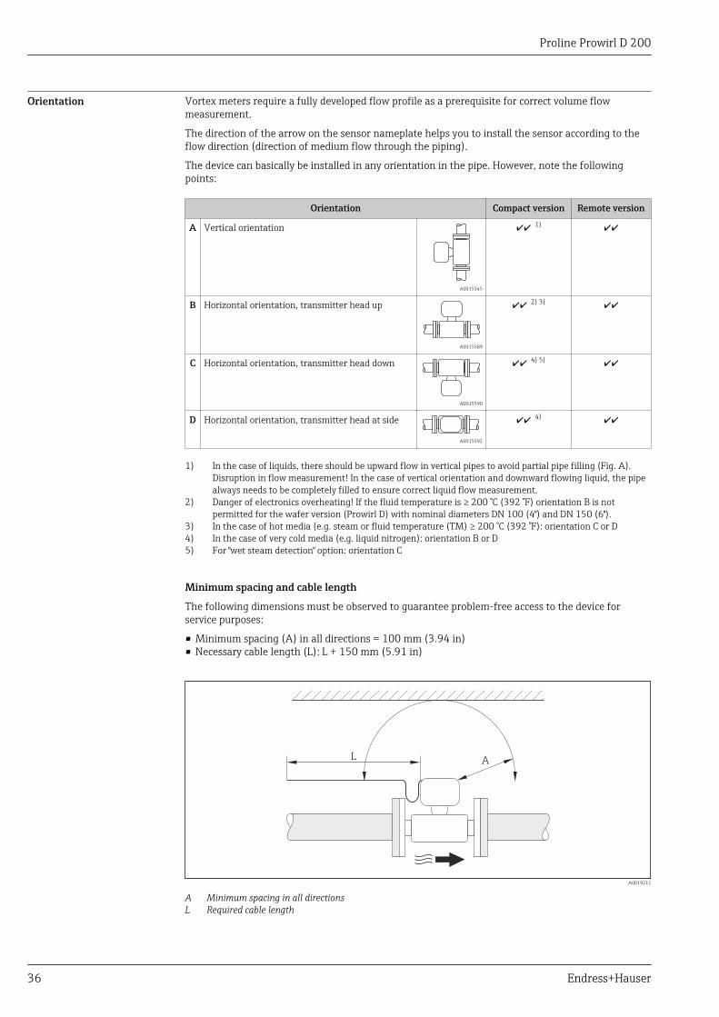
Orientation Vortex meters require a fully developed flow profile as a prerequisite for correct volume flowmeasurement.
The direction of the arrow on the sensor nameplate helps you to install the sensor according to theflow direction (direction of medium flow through the piping).
The device can basically be installed in any orientation in the pipe. However, note the followingpoints:
Orientation Compact version Remote version
A Vertical orientation
A0015545
1)
B Horizontal orientation, transmitter head up
A0015589
2) 3)
C Horizontal orientation, transmitter head down
A0015590
4) 5)
D Horizontal orientation, transmitter head at side
A0015592
4)
1) In the case of liquids, there should be upward flow in vertical pipes to avoid partial pipe filling (Fig. A).Disruption in flow measurement! In the case of vertical orientation and downward flowing liquid, the pipealways needs to be completely filled to ensure correct liquid flow measurement.
2) Danger of electronics overheating! If the fluid temperature is ≥ 200 °C (392 °F) orientation B is notpermitted for the wafer version (Prowirl D) with nominal diameters DN 100 (4") and DN 150 (6").
3) In the case of hot media (e.g. steam or fluid temperature (TM) ≥ 200 °C (392 °F): orientation C or D4) In the case of very cold media (e.g. liquid nitrogen): orientation B or D5) For "wet steam detection" option: orientation C
Minimum spacing and cable length
The following dimensions must be observed to guarantee problem-free access to the device forservice purposes:
• Minimum spacing (A) in all directions = 100 mm (3.94 in)• Necessary cable length (L): L + 150 mm (5.91 in)
AL
A0019211
A Minimum spacing in all directionsL Required cable length

Proline Prowirl D 200
Endress+Hauser 37
Rotating the electronics housing and the display
The electronics housing can be rotated continuously by 360° on the housing support. The display unitcan be rotated in 45° stages. This means you can read the display comfortably from all directions.
Inlet and outlet runs To attain the specified level of accuracy of the measuring device, the inlet and outlet runs mentionedbelow must be maintained at the very minimum. If there are several flow disturbances present, thelongest specified inlet run must be maintained.
15 × DN 5 × DN
1 217 × DN + 8 × h 5 × DN
750 × DN 5 × DN
6
25 × DN 5 × DN
40 × DN 5 × DN
54
20 × DN 5 × DN
3
20 × DN 5 × DN
h
A0019189
11 Minimum inlet and outlet runs with various flow obstructions
h Difference in expansion1 Reduction by one nominal diameter size2 Expansion3 T-piece4 Single elbow (90° elbow)5 Double elbow 3D (2 × 90° elbows, opposite, not on one plane)6 Double elbow (2 × 90° elbows, opposite)7 Control valve
If the required inlet runs cannot be observed, it is possible to install a specially designed flowconditioner (→ 41).
Flow conditioner
If the required inlet runs cannot be observed, it is possible to install a specially designed flowconditioner which can be ordered from Endress+Hauser. The flow conditioner is fitted between twopipe flanges and centered by the mounting bolts. Generally this reduces the inlet run needed to 10 ×DN with full accuracy.
8 x DN2 x DN 5 x DN
1
A0019208
1 Flow conditioner
Proline Prowirl D 200
38 Endress+Hauser
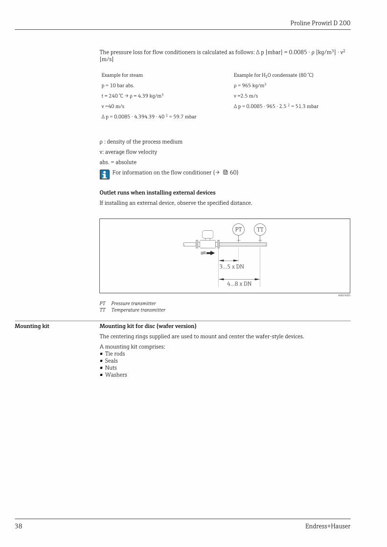
The pressure loss for flow conditioners is calculated as follows: ∆ p [mbar] = 0.0085 ⋅ ρ [kg/m3] ⋅ v2
[m/s]
Example for steam Example for H2O condensate (80 °C)
p = 10 bar abs. ρ = 965 kg/m3
t = 240 °C → ρ = 4.39 kg/m3 v =2.5 m/s
v =40 m/s ∆ p = 0.0085 ⋅ 965 ⋅ 2.5 2 = 51.3 mbar
∆ p = 0.0085 ⋅ 4.394.39 ⋅ 40 2 = 59.7 mbar
ρ : density of the process medium
v: average flow velocity
abs. = absolute
For information on the flow conditioner (→ 60)
Outlet runs when installing external devices
If installing an external device, observe the specified distance.
PT TT
3...5 x DN
4...8 x DN
A0019205
PT Pressure transmitterTT Temperature transmitter
Mounting kit Mounting kit for disc (wafer version)
The centering rings supplied are used to mount and center the wafer-style devices.
A mounting kit comprises:• Tie rods• Seals• Nuts• Washers

Proline Prowirl D 200
Endress+Hauser 39
1
2
3
A0019875
12 Mounting kit for wafer version
1 Nut, washer, tie rod2 Seal3 Centering ring (is supplied with the measuring device)
A mounting kit can be ordered separately (see the "Accessories" section (→ 77)).
Length of connecting cable To ensure correct measuring results when using the remote version,• observe the maximum permitted cable length Lmax.• The value for the cable length must be calculated if the cable cross-section differs from the
specification.For detailed information about calculating the length of the connecting cable, refer to theOperating Instructions for the device on the CD-ROM provided
Installing the wall-mounthousing
Wall mounting
80 (3.15)
80
(3
.15
)
19 (0.6)
!8
.6 (
0.3
9)
M 8
A0019864
13 Engineering unit mm (in)

Proline Prowirl D 200
40 Endress+Hauser
Shaft mounting
! 20…70
(! 0.79 to 2.75)
1
4 x SW 13
A0019862
14 Engineering unit mm (in)
1 Post mounting kit
Proline Prowirl D 200
Endress+Hauser 41
Special mountinginstructions
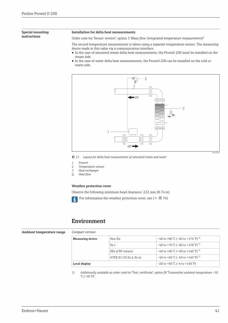
Installation for delta heat measurements
Order code for "Sensor version", option 3 "Mass flow (integrated temperature measurement)"
The second temperature measurement is taken using a separate temperature sensor. The measuringdevice reads in this value via a communication interface.• In the case of saturated steam delta heat measurements, the Prowirl 200 must be installed on the
steam side.• In the case of water delta heat measurements, the Prowirl 200 can be installed on the cold or
warm side.
Q
1
2
3
A0019209
15 Layout for delta heat measurement of saturated steam and water
1 Prowirl2 Temperature sensor3 Heat exchangerQ Heat flow
Weather protection cover
Observe the following minimum head clearance: 222 mm (8.74 in)
For information the weather protection cover, see (→ 76)
Environment
Ambient temperature range Compact version
Measuring device Non-Ex: –40 to +80 °C (–40 to +176 °F) 1)
Ex i: –40 to +70 °C (–40 to +158 °F) 1)
EEx d/XP version: –40 to +60 °C (–40 to +140 °F) 1)
ATEX II1/2G Ex d, Ex ia: –40 to +60 °C (–40 to +140 °F) 1)
Local display –20 to +60 °C (–4 to +140 °F)
1) Additionally available as order code for "Test, certificate", option JN "Transmitter ambient temperature –50°C (–58 °F)".
Proline Prowirl D 200
42 Endress+Hauser
Remote version
Transmitter Non-Ex: –40 to +80 °C (–40 to +176 °F) 1)
Ex i: –40 to +80 °C (–40 to +176 °F) 1)
Ex d: –40 to +60 °C (–40 to +140 °F) 1)
ATEX II1/2G Ex d, Ex ia: –40 to +60 °C (–40 to +140 °F) 1)
Sensor Non-Ex: –40 to +85 °C (–40 to +185 °F) 1)
Ex i: –40 to +85 °C (–40 to +185 °F) 1)
Ex d: –40 to +85 °C (–40 to +185 °F) 1)
ATEX II1/2G Ex d, Ex ia: –40 to +85 °C (–40 to +185 °F) 1)
Local display –20 to +60 °C (–4 to +140 °F)
1) Additionally available as order code for "Test, certificate", option JN "Transmitter ambient temperature –50°C (–58 °F)".
‣ If operating outdoors:Avoid direct sunlight, particularly in warm climatic regions.
Weather protection covers can be ordered from Endress+Hauser: see "Accessories" section(→ 76)
Temperature tables
Tm = fluid temperature, Ta = ambient temperature
The following interdependencies between the permitted ambient and fluid temperatures apply whenoperating the device in hazardous areas:
Compact version
Order code for "Sensor version", option 1 "Volume flow, basis"; option 3 "Mass flow (integratedtemperature measurement)"
Order code for "Sensor version", option 2 "Volume flow, high-temperature/low-temperature"
The following temperature tables apply for the low-temperature version (→ 42).
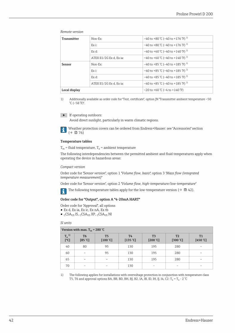
Order code for "Output", option A "4-20mA HART"
Order code for "Approval", all options• Ex d, Ex ia, Ex ic, Ex nA, Ex tb• CCSAUS IS, CCSAUS XP, CCSAUS NI
SI units
Version with max. Tm = 280 °C
Ta 1)
[ºC]T6
[85 °C]T5
[100 °C]T4
[135 °C]T3
[200 °C]T2
[300 °C]T1
[450 °C]
40 80 95 130 195 280 –
60 – 95 130 195 280 –
65 – – 130 195 280 –
70 – – 130 – – –
1) The following applies for installations with overvoltage protection in conjunction with temperature classT5, T6 and approval options BA, BB, BD, BH, BJ, B2, IA, IB, ID, IH, IJ, I4, C2: Ta = Ta - 2 °C
Proline Prowirl D 200
Endress+Hauser 43
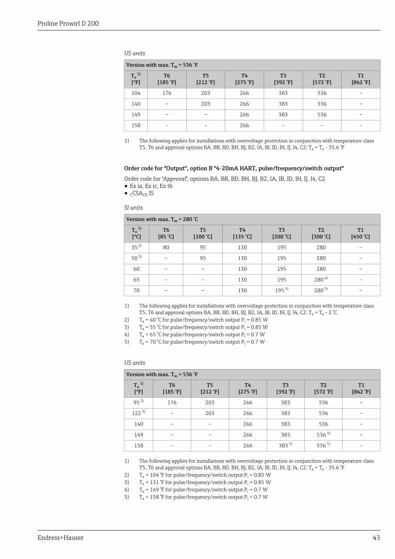
US units
Version with max. Tm = 536 °F
Ta 1)
[ºF]T6
[185 °F]T5
[212 °F]T4
[275 °F]T3
[392 °F]T2
[572 °F]T1
[842 °F]
104 176 203 266 383 536 –
140 – 203 266 383 536 –
149 – – 266 383 536 –
158 – – 266 – – –
1) The following applies for installations with overvoltage protection in conjunction with temperature classT5, T6 and approval options BA, BB, BD, BH, BJ, B2, IA, IB, ID, IH, IJ, I4, C2: Ta = Ta - 35.6 °F
Order code for "Output", option B "4-20mA HART, pulse/frequency/switch output"
Order code for "Approval", options BA, BB, BD, BH, BJ, B2, IA, IB, ID, IH, IJ, I4, C2• Ex ia, Ex ic, Ex tb• CCSAUS IS
SI units
Version with max. Tm = 280 °C
Ta 1)
[ºC]T6
[85 °C]T5
[100 °C]T4
[135 °C]T3
[200 °C]T2
[300 °C]T1
[450 °C]
35 2) 80 95 130 195 280 –
50 3) – 95 130 195 280 –
60 – – 130 195 280 –
65 – – 130 195 280 4) –
70 – – 130 195 5) 280 5) –
1) The following applies for installations with overvoltage protection in conjunction with temperature classT5, T6 and approval options BA, BB, BD, BH, BJ, B2, IA, IB, ID, IH, IJ, I4, C2: Ta = Ta - 2 °C
2) Ta = 40 °C for pulse/frequency/switch output Pi = 0.85 W3) Ta = 55 °C for pulse/frequency/switch output Pi = 0.85 W4) Ta = 65 °C for pulse/frequency/switch output Pi = 0.7 W5) Ta = 70 °C for pulse/frequency/switch output Pi = 0.7 W
US units
Version with max. Tm = 536 °F
Ta 1)
[ºF]T6
[185 °F]T5
[212 °F]T4
[275 °F]T3
[392 °F]T2
[572 °F]T1
[842 °F]
95 2) 176 203 266 383 536 –
122 3) – 203 266 383 536 –
140 – – 266 383 536 –
149 – – 266 383 536 4) –
158 – – 266 383 5) 536 5) –
1) The following applies for installations with overvoltage protection in conjunction with temperature classT5, T6 and approval options BA, BB, BD, BH, BJ, B2, IA, IB, ID, IH, IJ, I4, C2: Ta = Ta - 35.6 °F
2) Ta = 104 °F for pulse/frequency/switch output Pi = 0.85 W3) Ta = 131 °F for pulse/frequency/switch output Pi = 0.85 W4) Ta = 149 °F for pulse/frequency/switch output Pi = 0.7 W5) Ta = 158 °F for pulse/frequency/switch output Pi = 0.7 W
Proline Prowirl D 200
44 Endress+Hauser
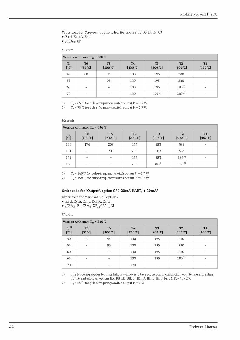
Order code for "Approval", options BC, BG, BK, B3, IC, IG, IK, I5, C3• Ex d, Ex nA, Ex tb• CCSAUS XP
SI units
Version with max. Tm = 280 °C
Ta[ºC]
T6[85 °C]
T5[100 °C]
T4[135 °C]
T3[200 °C]
T2[300 °C]
T1[450 °C]
40 80 95 130 195 280 –
55 – 95 130 195 280 –
65 – – 130 195 280 1) –
70 – – 130 195 2) 280 2) –
1) Ta = 65 °C for pulse/frequency/switch output Pi = 0.7 W2) Ta = 70 °C for pulse/frequency/switch output Pi = 0.7 W
US units
Version with max. Tm = 536 °F
Ta[ºF]
T6[185 °F]
T5[212 °F]
T4[275 °F]
T3[392 °F]
T2[572 °F]
T1[842 °F]
104 176 203 266 383 536 –
131 – 203 266 383 536 –
149 – – 266 383 536 1) –
158 – – 266 383 2) 536 2) –
1) Ta = 149 °F for pulse/frequency/switch output Pi = 0.7 W2) Ta = 158 °F for pulse/frequency/switch output Pi = 0.7 W
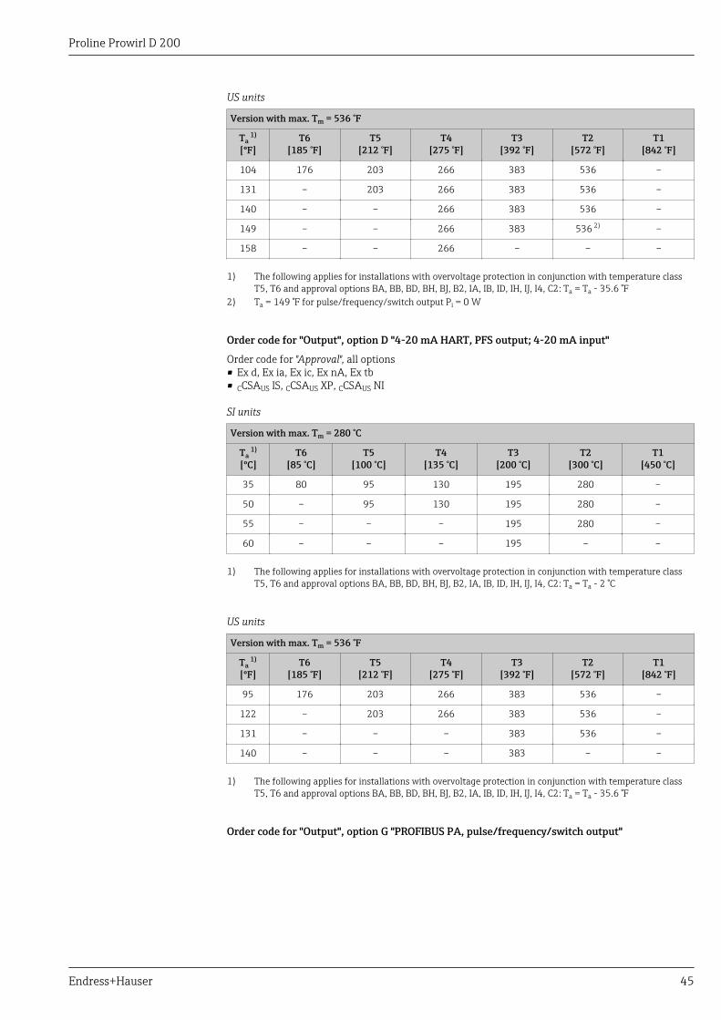
Order code for "Output", option C "4-20mA HART, 4-20mA"
Order code for "Approval", all options• Ex d, Ex ia, Ex ic, Ex nA, Ex tb• CCSAUS IS, CCSAUS XP, CCSAUS NI
SI units
Version with max. Tm = 280 °C
Ta 1)
[ºC]T6
[85 °C]T5
[100 °C]T4
[135 °C]T3
[200 °C]T2
[300 °C]T1
[450 °C]
40 80 95 130 195 280 –
55 – 95 130 195 280 –
60 – – 130 195 280 –
65 – – 130 195 280 2) –
70 – – 130 – – –
1) The following applies for installations with overvoltage protection in conjunction with temperature classT5, T6 and approval options BA, BB, BD, BH, BJ, B2, IA, IB, ID, IH, IJ, I4, C2: Ta = Ta - 2 °C
2) Ta = 65 °C for pulse/frequency/switch output Pi = 0 W
Proline Prowirl D 200
Endress+Hauser 45
US units
Version with max. Tm = 536 °F
Ta 1)
[ºF]T6
[185 °F]T5
[212 °F]T4
[275 °F]T3
[392 °F]T2
[572 °F]T1
[842 °F]
104 176 203 266 383 536 –
131 – 203 266 383 536 –
140 – – 266 383 536 –
149 – – 266 383 536 2) –
158 – – 266 – – –
1) The following applies for installations with overvoltage protection in conjunction with temperature classT5, T6 and approval options BA, BB, BD, BH, BJ, B2, IA, IB, ID, IH, IJ, I4, C2: Ta = Ta - 35.6 °F
2) Ta = 149 °F for pulse/frequency/switch output Pi = 0 W
Order code for "Output", option D "4-20 mA HART, PFS output; 4-20 mA input"
Order code for "Approval", all options• Ex d, Ex ia, Ex ic, Ex nA, Ex tb• CCSAUS IS, CCSAUS XP, CCSAUS NI
SI units
Version with max. Tm = 280 °C
Ta 1)
[ºC]T6
[85 °C]T5
[100 °C]T4
[135 °C]T3
[200 °C]T2
[300 °C]T1
[450 °C]
35 80 95 130 195 280 –
50 – 95 130 195 280 –
55 – – – 195 280 –
60 – – – 195 – –
1) The following applies for installations with overvoltage protection in conjunction with temperature classT5, T6 and approval options BA, BB, BD, BH, BJ, B2, IA, IB, ID, IH, IJ, I4, C2: Ta = Ta - 2 °C
US units
Version with max. Tm = 536 °F
Ta 1)
[ºF]T6
[185 °F]T5
[212 °F]T4
[275 °F]T3
[392 °F]T2
[572 °F]T1
[842 °F]
95 176 203 266 383 536 –
122 – 203 266 383 536 –
131 – – – 383 536 –
140 – – – 383 – –
1) The following applies for installations with overvoltage protection in conjunction with temperature classT5, T6 and approval options BA, BB, BD, BH, BJ, B2, IA, IB, ID, IH, IJ, I4, C2: Ta = Ta - 35.6 °F
Order code for "Output", option G "PROFIBUS PA, pulse/frequency/switch output"

Proline Prowirl D 200
46 Endress+Hauser
Order code for "Approval", all options• Ex d, Ex ia, Ex ic, Ex nA, Ex tb• CCSAUS IS, CCSAUS XP, CCSAUS NI
SI units
Version with max. Tm = 280 °C
Ta 1)
[ºC]T6
[85 °C]T5
[100 °C]T4
[135 °C]T3
[200 °C]T2
[300 °C]T1
[450 °C]
40 80 95 130 195 280 –
50 2) – 95 130 195 280 –
60 – – 130 195 280 –
65 – – 130 195 280 3) –
70 – – 130 195 4) 280 4) –
1) The following applies for installations with overvoltage protection in conjunction with temperature classT5, T6 and approval options BA, BB, BD, BH, BJ, B2, IA, IB, ID, IH, IJ, I4, C2: Ta = Ta - 2 °C
2) Ta = 60 °C for pulse/frequency/switch output Pi = 0 W3) Ta = 65 °C for pulse/frequency/switch output Pi = 0 W4) Ta = 70 °C for pulse/frequency/switch output Pi = 0 W
US units
Version with max. Tm = 536 °F
Ta 1)
[°F]T6
[185 °F]T5
[212 °F]T4
[275 °F]T3
[392 °F]T2
[572 °F]T1
[842 °F]
104 176 203 266 383 536 –
122 2) – 203 266 383 536 –
140 – – 266 383 536 –
149 – – 266 383 536 3) –
158 – – 266 383 4) 536 4) –
1) The following applies for installations with overvoltage protection in conjunction with temperature classT5, T6 and approval options BA, BB, BD, BH, BJ, B2, IA, IB, ID, IH, IJ, I4, C2: Ta = Ta - 35.6 °F
2) Ta = 140 °F for pulse/frequency/switch output Pi = 0 W3) Ta = 149 °F for pulse/frequency/switch output Pi = 0 W4) Ta = 158 °F for pulse/frequency/switch output Pi = 0 W
High-temperature version
Order code for "Sensor version", option 2 "Volume flow, high-temperature/low-temperature"
The following temperature tables apply for the high-temperature version (→ 47).
Order code for "Output", option A "4-20mA HART"

Proline Prowirl D 200
Endress+Hauser 47
Order code for "Approval", all options• Ex d, Ex ia, Ex ic, Ex nA, Ex tb• CCSAUS IS, CCSAUS XP, CCSAUS NI
SI units
Version with max. Tm = 440 °C
Ta 1)
[ºC]T6
[85 °C]T5
[100 °C]T4
[135 °C]T3
[200 °C]T2
[300 °C]T1
[450 °C]
40 80 95 130 195 290 440
60 – 95 130 195 290 440
70 – – 130 195 290 440
1) The following applies for installations with overvoltage protection in conjunction with temperature classT5, T6 and approval options BA, BB, BD, BH, BJ, B2, IA, IB, ID, IH, IJ, I4, C2: Ta = Ta - 2 °C
US units
Version with max. Tm = 824 °F
Ta 1)
[ºF]T6
[185 °F]T5
[212 °F]T4
[275 °F]T3
[392 °F]T2
[572 °F]T1
[842 °F]
104 176 203 266 383 554 824
140 – 203 266 383 554 824
158 – – 266 383 554 824
1) The following applies for installations with overvoltage protection in conjunction with temperature classT5, T6 and approval options BA, BB, BD, BH, BJ, B2, IA, IB, ID, IH, IJ, I4, C2: Ta = Ta - 35.6 °F
Order code for "Output", option B "4-20mA HART, pulse/frequency/switch output"
Order code for "Approval", options BA, BB, BD, BH, BJ, B2, IA, IB, ID, IH, IJ, I4, C2• Ex ia, Ex ic, Ex tb• CCSAUS IS
SI units
Version with max. Tm = 440 °C
Ta 1)
[ºC]T6
[85 °C]T5
[100 °C]T4
[135 °C]T3
[200 °C]T2
[300 °C]T1
[450 °C]
35 2) 80 95 130 195 290 440
50 3) – 95 130 195 290 440
65 – – 130 195 290 440
70 – – 130 195 4) 290 440 4)
1) The following applies for installations with overvoltage protection in conjunction with temperature classT5, T6 and approval options BA, BB, BD, BH, BJ, B2, IA, IB, ID, IH, IJ, I4, C2: Ta = Ta - 2 °C
2) Ta = 40 °C for pulse/frequency/switch output Pi = 0.85 W3) Ta = 55 °C for pulse/frequency/switch output Pi = 0.85 W4) Ta = 70 °C for pulse/frequency/switch output Pi = 0.85 W
US units
Version with max. Tm = 824 °F
Ta 1)
[ºF]T6
[185 °F]T5
[212 °F]T4
[275 °F]T3
[392 °F]T2
[572 °F]T1
[842 °F]
95 2) 176 203 266 383 554 824
122 3) – 203 266 383 554 824

Proline Prowirl D 200
48 Endress+Hauser
Version with max. Tm = 824 °F
Ta 1)
[ºF]T6
[185 °F]T5
[212 °F]T4
[275 °F]T3
[392 °F]T2
[572 °F]T1
[842 °F]
149 – – 266 383 554 824
158 – – 266 383 4) 554 824 4)
1) The following applies for installations with overvoltage protection in conjunction with temperature classT5, T6 and approval options BA, BB, BD, BH, BJ, B2, IA, IB, ID, IH, IJ, I4, C2: Ta = Ta - 35.6 °F
2) Ta = 104 °F for pulse/frequency/switch output Pi = 0.85 W3) Ta = 131 °F for pulse/frequency/switch output Pi = 0.85 W4) Ta = 158 °F for pulse/frequency/switch output Pi = 0.85 W
Order code for "Approval", options BC, BG, BK, B3, IC, IG, IK, I5, C3• Ex d, Ex nA, Ex tb• CCSAUS XP
SI units
Version with max. Tm = 440 °C
Ta[ºC]
T6[85 °C]
T5[100 °C]
T4[135 °C]
T3[200 °C]
T2[300 °C]
T1[450 °C]
40 80 95 130 195 290 440
55 – 95 130 195 290 440
65 – – 130 195 290 440
70 – – 130 195 1) 290 1) 440 1)
1) Ta = 70 °C for pulse/frequency/switch output Pi = 0.85 W
US units
Version with max. Tm = 824 °F
Ta[ºF]
T6[185 °F]
T5[212 °F]
T4[275 °F]
T3[392 °F]
T2[572 °F]
T1[842 °F]
104 176 203 266 383 554 824
131 – 203 266 383 554 824
149 – – 266 383 554 824
158 – – 266 383 1) 554 1) 824 1)
1) Ta = 158 °F for pulse/frequency/switch output Pi = 0.85 W
Order code for "Output", option C "4-20mA HART, 4-20mA"
Order code for "Approval", all options• Ex d, Ex ia, Ex ic, Ex nA, Ex tb• CCSAUS IS, CCSAUS XP, CCSAUS NI
SI units
Version with max. Tm = 440 °C
Ta 1)
[ºC]T6
[85 °C]T5
[100 °C]T4
[135 °C]T3
[200 °C]T2
[300 °C]T1
[450 °C]
40 80 95 130 195 290 440
55 – 95 130 195 290 440
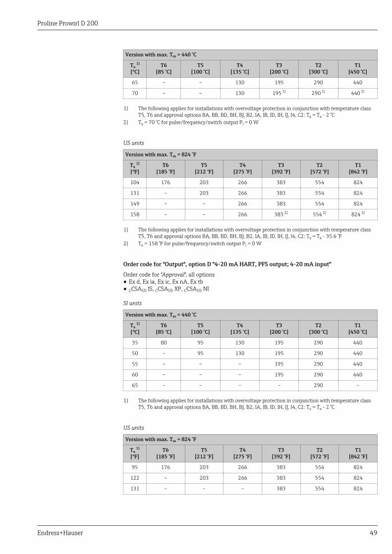
Proline Prowirl D 200
Endress+Hauser 49
Version with max. Tm = 440 °C
Ta 1)
[ºC]T6
[85 °C]T5
[100 °C]T4
[135 °C]T3
[200 °C]T2
[300 °C]T1
[450 °C]
65 – – 130 195 290 440
70 – – 130 195 2) 290 2) 440 2)
1) The following applies for installations with overvoltage protection in conjunction with temperature classT5, T6 and approval options BA, BB, BD, BH, BJ, B2, IA, IB, ID, IH, IJ, I4, C2: Ta = Ta - 2 °C
2) Ta = 70 °C for pulse/frequency/switch output Pi = 0 W
US units
Version with max. Tm = 824 °F
Ta 1)
[ºF]T6
[185 °F]T5
[212 °F]T4
[275 °F]T3
[392 °F]T2
[572 °F]T1
[842 °F]
104 176 203 266 383 554 824
131 – 203 266 383 554 824
149 – – 266 383 554 824
158 – – 266 383 2) 554 2) 824 2)
1) The following applies for installations with overvoltage protection in conjunction with temperature classT5, T6 and approval options BA, BB, BD, BH, BJ, B2, IA, IB, ID, IH, IJ, I4, C2: Ta = Ta - 35.6 °F
2) Ta = 158 °F for pulse/frequency/switch output Pi = 0 W
Order code for "Output", option D "4-20 mA HART, PFS output; 4-20 mA input"
Order code for "Approval", all options• Ex d, Ex ia, Ex ic, Ex nA, Ex tb• CCSAUS IS, CCSAUS XP, CCSAUS NI
SI units
Version with max. Tm = 440 °C
Ta 1)
[ºC]T6
[85 °C]T5
[100 °C]T4
[135 °C]T3
[200 °C]T2
[300 °C]T1
[450 °C]
35 80 95 130 195 290 440
50 – 95 130 195 290 440
55 – – – 195 290 440
60 – – – 195 290 440
65 – – – – 290 –
1) The following applies for installations with overvoltage protection in conjunction with temperature classT5, T6 and approval options BA, BB, BD, BH, BJ, B2, IA, IB, ID, IH, IJ, I4, C2: Ta = Ta - 2 °C
US units
Version with max. Tm = 824 °F
Ta 1)
[ºF]T6
[185 °F]T5
[212 °F]T4
[275 °F]T3
[392 °F]T2
[572 °F]T1
[842 °F]
95 176 203 266 383 554 824
122 – 203 266 383 554 824
131 – – – 383 554 824
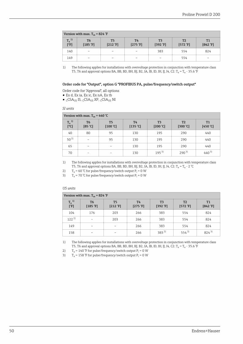
Proline Prowirl D 200
50 Endress+Hauser
Version with max. Tm = 824 °F
Ta 1)
[ºF]T6
[185 °F]T5
[212 °F]T4
[275 °F]T3
[392 °F]T2
[572 °F]T1
[842 °F]
140 – – – 383 554 824
149 – – – – 554 –
1) The following applies for installations with overvoltage protection in conjunction with temperature classT5, T6 and approval options BA, BB, BD, BH, BJ, B2, IA, IB, ID, IH, IJ, I4, C2: Ta = Ta - 35.6 °F
Order code for "Output", option G "PROFIBUS PA, pulse/frequency/switch output"
Order code for "Approval", all options• Ex d, Ex ia, Ex ic, Ex nA, Ex tb• CCSAUS IS, CCSAUS XP, CCSAUS NI
SI units
Version with max. Tm = 440 °C
Ta 1)
[ºC]T6
[85 °C]T5
[100 °C]T4
[135 °C]T3
[200 °C]T2
[300 °C]T1
[450 °C]
40 80 95 130 195 290 440
50 2) – 95 130 195 290 440
65 – – 130 195 290 440
70 – – 130 195 3) 290 3) 440 3)
1) The following applies for installations with overvoltage protection in conjunction with temperature classT5, T6 and approval options BA, BB, BD, BH, BJ, B2, IA, IB, ID, IH, IJ, I4, C2: Ta = Ta - 2 °C
2) Ta = 60 °C for pulse/frequency/switch output Pi = 0 W3) Ta = 70 °C for pulse/frequency/switch output Pi = 0 W
US units
Version with max. Tm = 824 °F
Ta 1)
[°F]T6
[185 °F]T5
[212 °F]T4
[275 °F]T3
[392 °F]T2
[572 °F]T1
[842 °F]
104 176 203 266 383 554 824
122 2) – 203 266 383 554 824
149 – – 266 383 554 824
158 – – 266 383 3) 554 3) 824 3)
1) The following applies for installations with overvoltage protection in conjunction with temperature classT5, T6 and approval options BA, BB, BD, BH, BJ, B2, IA, IB, ID, IH, IJ, I4, C2: Ta = Ta - 35.6 °F
2) Ta = 140 °F for pulse/frequency/switch output Pi = 0 W3) Ta = 158 °F for pulse/frequency/switch output Pi = 0 W

Proline Prowirl D 200
Endress+Hauser 51
Remote version
Transmitter
Order code for "Housing", option J "GT20 two-chamber, remote G314, aluminum coated"; option K"GT20 two-chamber, remote G315, 316L"
SI units
Order code for "Output", option Order code for"Approval", option
T6[85 °C]
T5[100 °C]
T4[135 °C]
A All 40 60 75
B BA, BB, BD, BH, BJ, B2, IA,IB, ID, IH, IJ, I4, C2
35 1) 50 2) 70 3)
BC, BG, BK, B3, IC, IG, IK,I5, C3
40 55 70 3)
C All 40 55 70 4)
D All 35 5) 50 5) 65
G All 40 55 70 4)
1) Ta = 40 °C for pulse/frequency/switch output Pi = 0.85 W2) Ta = 60 °C for pulse/frequency/switch output Pi = 0.85 W3) Ta = 75 °C for pulse/frequency/switch output Pi = 0.85 W4) Ta = 75 °C for pulse/frequency/switch output Pi = 0 W5) The following applies for installations with overvoltage protection in conjunction with temperature class
T5, T6 and approval options BA, BB, BD, BH, BJ, B2, IA, IB, ID, IH, IJ, I4, C2: Ta = Ta - 2 °C
US units
Order code for "Output", option Order code for"Approval", option
T6[185 °F]
T5[212 °F]
T4[275 °F]
A All 104 140 167
B BA, BB, BD, BH, BJ, B2, IA,IB, ID, IH, IJ, I4, C2
95 1) 122 2) 158 3)
BC, BG, BK, B3, IC, IG, IK,I5, C3
104 131 158 3)
C All 104 131 158 4)
D All 95 5) 122 5) 149
G All 104 131 158 4)
1) Ta = 104 °F for pulse/frequency/switch output Pi = 0.85 W2) Ta = 140 °F for pulse/frequency/switch output Pi = 0.85 W3) Ta = 167 °F for pulse/frequency/switch output Pi = 0.85 W4) Ta = 167 °F for pulse/frequency/switch output Pi = 0 W5) The following applies for installations with overvoltage protection in conjunction with temperature class
T5, T6 and approval options BA, BB, BD, BH, BJ, B2, IA, IB, ID, IH, IJ, I4, C2: Ta = Ta - 35.6 °F
Sensor
Order code for "Sensor version", option 1 "Volume flow, basis"; option 3 "Mass flow (integratedtemperature measurement)"
Order code for "Sensor version", option 2 "Volume flow, high-temperature/low-temperature"

Proline Prowirl D 200
52 Endress+Hauser
The following temperature tables apply for the low-temperature version (→ 52).
SI units
Version with max. Tm = 280 °C
Ta[ºC]
T6[85 °C]
T5[100 °C]
T4[135 °C]
T3[200 °C]
T2[300 °C]
T1[450 °C]
55 80 95 130 195 280 –
70 – 95 130 195 280 –
85 – – 130 195 280 –
US units
Version with max. Tm = 536 °F
Ta[°F]
T6[185 °F]
T5[212 °F]
T4[275 °F]
T3[392 °F]
T2[572 °F]
T1[842 °F]
104 176 203 266 383 536 –
122 – 203 266 383 536 –
149 – – 266 383 536 –
High-temperature version
Order code for "Sensor version", option 2 "Volume flow, high-temperature/low-temperature"
The following temperature tables apply for the high-temperature version (→ 52).
SI units
Version with max. Tm = 440 °C
Ta[ºC]
T6[85 °C]
T5[100 °C]
T4[135 °C]
T3[200 °C]
T2[300 °C]
T1[450 °C]
55 80 95 130 195 290 440
70 – 95 130 195 290 440
85 – – 130 195 290 440
US units
Version with max. Tm = 824 °F
Ta[°F]
T6[185 °F]
T5[212 °F]
T4[275 °F]
T3[392 °F]
T2[572 °F]
T1[842 °F]
131 176 203 266 383 554 824
158 – 203 266 383 554 824
185 – – 266 383 554 824
Storage temperature All components apart from the display modules:–50 to +80 °C (–58 to +176 °F)Display modules:–40 to +80 °C (–40 to +176 °F)
Climate class DIN EN 60068-2-38 (test Z/AD)
Proline Prowirl D 200
Endress+Hauser 53
Degree of protection Transmitter• As standard: IP66/67, type 4X enclosure• When housing is open: IP20, type 1 enclosure• Display module: IP20, type 1 enclosureSensorIP66/67, type 4X enclosureConnectorIP67, only in screwed situation
Vibration resistance • For compact/remote version made of coated aluminum and remote version made of stainless steel:Acceleration up to 2g (if gain set to factory setting), 10 to 500 Hz, following IEC 60068-2-6
• For the compact version made of stainless steel:Acceleration up to 1g (if gain set to factory setting), 10 to 500 Hz, following IEC 60068-2-6
Electromagneticcompatibility (EMC)
As per IEC/EN 61326 and NAMUR Recommendation 21 (NE 21)For details refer to the Declaration of Conformity.
Process
Medium temperature range DSC sensor 3)
Order code for "Sensor version":• Option 1 "Volume flow, basis":
–40 to +260 °C (–40 to +500 °F), stainless steel• Option 2 "Volume flow, high-temperature/low temperature":
–200 to +400 °C (–328 to +752 °F), stainless steel• Option 3 "Mass flow (integrated temperature measurement)":
–200 to +400 °C (–328 to +752 °F), stainless steel
DSC sensor 3)
Order code for "Sensor option":Option CD "Harsh environment, DSC sensor components, Alloy C22":–200 to +400 °C (–328 to +752 °F), DSC sensor Alloy C22
DSC sensor 3)
Special version for very high fluid temperatures (on request):• –200 to +450 °C (–328 to +842 °F)• –200 to +440 °C (–328 to +824 °F), Ex version•Seals• –200 to +400 °C (–328 to +752 °F) for graphite (standard)• –15 to +175 °C (+5 to +347 °F) for Viton• –20 to +275 °C (–4 to +527 °F) for Kalrez• –200 to +260 °C (–328 to +500 °F) for Gylon
Pressure-temperatureratings
The following pressure-temperature ratings refer to the entire device and not just the processconnection.
The pressure-temperature rating for the specific measuring device is programmed into the software.If values exceed the curve range a warning is displayed. Depending on the system configuration andsensor version, the pressure and temperature are determined by entering, reading in or calculatingvalues.
3) Capacitance sensor

Proline Prowirl D 200
54 Endress+Hauser
Process connection: wafer flange to EN 1092-1 (DIN 2501)
PN40
PN25
PN16
PN10
0
10
20
30
40
[bar]
-200 -100 0 100 200 300 400
0
100
200
[bar]
300
400
500
600
[psi]
-400 -200 0 800200 600400
[°C]
[°F]
A0020879-EN
16 Process connection material: stainless cast steel, multiple certifications, 1.4408 (CF3M)
Process connection: wafer flange to ASME B16.5
Cl.300
Cl.150
00
20
40
60
[bar]
1000
[psi]
-200 -100 0 100 200 300 400
-400 -200 0 800200 600400
[°C]
[°F]
A0020880-EN
17 Process connection material: stainless cast steel, multiple certifications, 1.4408 (CF3M)
Process connection: wafer flange to JIS B2220
20 K
10 K
-200 -100 0 100 200 300 400
0
10
20
[bar]
0
100
200
[bar]
300
[psi]
-400 -200 0 800200 600400 [°F]
[°C]
A0020881-EN
18 Process connection material: stainless cast steel, multiple certifications, 1.4408 (CF3M)
Pressure loss For a precise calculation, use the Applicator(→ 78).
Thermal insulation For optimum temperature measurement and mass calculation, heat transfer at the sensor must beavoided for some fluids. This can be ensured by installing thermal insulation. A wide range ofmaterials can be used for the required insulation.

Proline Prowirl D 200
Endress+Hauser 55
This applies for:• Compact version• Remote sensor version
The maximum insulation height permitted is illustrated in the diagram:
1
A0019212
1 Maximum insulation height
‣ When insulating, ensure that a sufficiently large area of the housing support remains exposed.The uncovered part serves as a radiator and protects the electronics from overheating and excessivecooling.
Vibrations The correct operation of the measuring system is not affected by plant vibrations up to 1 g,10 to 500 Hz. Therefore no special measures are needed to secure the sensors.
Mechanical construction
Design, dimensions Compact version
Order code for "Housing", option B "GT18, two-chamber, 316L"; option C "GT20, two-chamber,aluminum coated"
D
E F
A
B C
G
H
LK
di
±0.5( )±0.02
A0020271
19 Engineering unit mm (in)
Dimensions in SI units
DN A B 1) C D 2) E F 2) G 3) 4) H 3) 4) L K di
[mm] [mm] [mm] [mm] [mm] [mm] [mm] [mm] [mm] [mm] [mm] [mm]
15 162 102 60 165 75 90 252.5 275.9 65 5) 5)
25 162 102 60 165 75 90 262.0 294.4 65 5) 5)
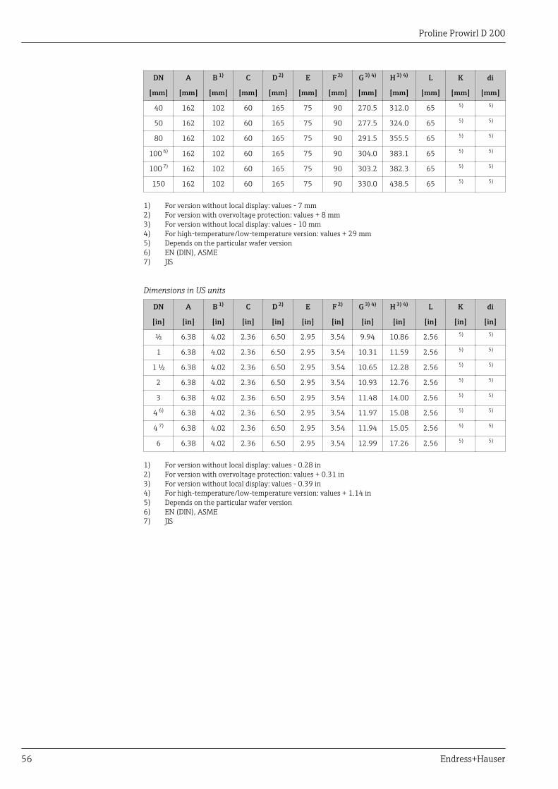
Proline Prowirl D 200
56 Endress+Hauser
DN A B 1) C D 2) E F 2) G 3) 4) H 3) 4) L K di
[mm] [mm] [mm] [mm] [mm] [mm] [mm] [mm] [mm] [mm] [mm] [mm]
40 162 102 60 165 75 90 270.5 312.0 65 5) 5)
50 162 102 60 165 75 90 277.5 324.0 65 5) 5)
80 162 102 60 165 75 90 291.5 355.5 65 5) 5)
100 6) 162 102 60 165 75 90 304.0 383.1 65 5) 5)
100 7) 162 102 60 165 75 90 303.2 382.3 65 5) 5)
150 162 102 60 165 75 90 330.0 438.5 65 5) 5)
1) For version without local display: values - 7 mm2) For version with overvoltage protection: values + 8 mm3) For version without local display: values - 10 mm4) For high-temperature/low-temperature version: values + 29 mm5) Depends on the particular wafer version6) EN (DIN), ASME7) JIS
Dimensions in US units
DN A B 1) C D 2) E F 2) G 3) 4) H 3) 4) L K di
[in] [in] [in] [in] [in] [in] [in] [in] [in] [in] [in] [in]
½ 6.38 4.02 2.36 6.50 2.95 3.54 9.94 10.86 2.56 5) 5)
1 6.38 4.02 2.36 6.50 2.95 3.54 10.31 11.59 2.56 5) 5)
1 ½ 6.38 4.02 2.36 6.50 2.95 3.54 10.65 12.28 2.56 5) 5)
2 6.38 4.02 2.36 6.50 2.95 3.54 10.93 12.76 2.56 5) 5)
3 6.38 4.02 2.36 6.50 2.95 3.54 11.48 14.00 2.56 5) 5)
4 6) 6.38 4.02 2.36 6.50 2.95 3.54 11.97 15.08 2.56 5) 5)
4 7) 6.38 4.02 2.36 6.50 2.95 3.54 11.94 15.05 2.56 5) 5)
6 6.38 4.02 2.36 6.50 2.95 3.54 12.99 17.26 2.56 5) 5)
1) For version without local display: values - 0.28 in2) For version with overvoltage protection: values + 0.31 in3) For version without local display: values - 0.39 in4) For high-temperature/low-temperature version: values + 1.14 in5) Depends on the particular wafer version6) EN (DIN), ASME7) JIS
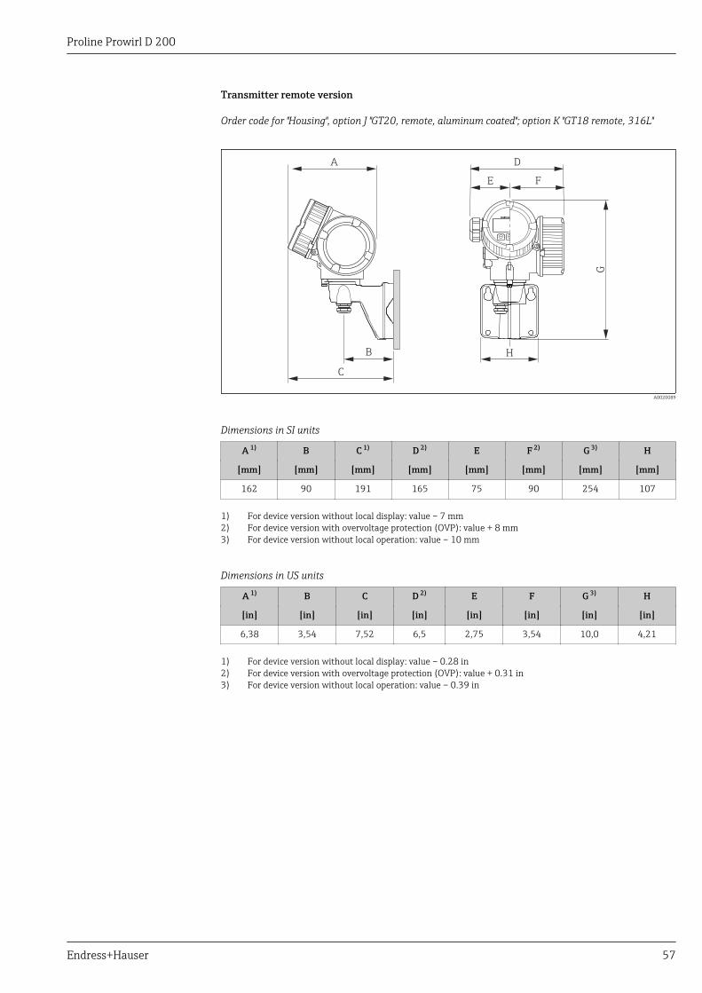
Proline Prowirl D 200
Endress+Hauser 57
Transmitter remote version
Order code for "Housing", option J "GT20, remote, aluminum coated"; option K "GT18 remote, 316L"
B
C
H
D
G
A
E F
A0020089
Dimensions in SI units
A 1) B C 1) D 2) E F 2) G 3) H
[mm] [mm] [mm] [mm] [mm] [mm] [mm] [mm]
162 90 191 165 75 90 254 107
1) For device version without local display: value – 7 mm2) For device version with overvoltage protection (OVP): value + 8 mm3) For device version without local operation: value – 10 mm
Dimensions in US units
A 1) B C D 2) E F G 3) H
[in] [in] [in] [in] [in] [in] [in] [in]
6,38 3,54 7,52 6,5 2,75 3,54 10,0 4,21
1) For device version without local display: value – 0.28 in2) For device version with overvoltage protection (OVP): value + 0.31 in3) For device version without local operation: value – 0.39 in

Proline Prowirl D 200
58 Endress+Hauser
Sensor remote version
Order code for "Housing", option J "GT20, remote, aluminum coated"; option K "GT18, remote, 316L"
L
C
B
D
E
F
A
K
di
±0.5( )±0.02
A0020264
20 Engineering unit mm (in)
Dimensions in SI units
DN A B C D E 1) F 1) L K di
[mm] [mm] [mm] [mm] [mm] [mm] [mm] [mm] [mm] [mm]
15 94.3 134.3 107.3 115.8 222.8 246.2 65 2) 2)
25 94.3 134.3 107.3 115.8 232.3 264.7 65 2) 2)
40 94.3 134.3 107.3 115.8 240.8 282.3 65 2) 2)
50 94.3 134.3 107.3 115.8 247.8 294.3 65 2) 2)
80 94.3 134.3 107.3 115.8 261.8 325.8 65 2) 2)
100 3) 94.3 134.3 107.3 115.8 274.3 353.4 65 2) 2)
100 4) 94.3 134.3 107.3 115.8 273.5 352.6 65 2) 2)
150 94.3 134.3 107.3 115.8 300.3 408.8 65 2) 2)
1) For high-temperature/low-temperature version: values + 29 mm2) Depends on the particular wafer version3) EN (DIN), ASME4) JIS
Dimensions in US units
DN A B C D E 1) F 1) L K di
[in] [in] [in] [in] [in] [in] [in] [in] [in] [in]
½ 3.71 5.29 4.22 4.56 8.77 9.69 2.56 2) 2)
1 3.71 5.29 4.22 4.56 9.15 10.42 2.56 2) 2)
1 ½ 3.71 5.29 4.22 4.56 9.48 11.11 2.56 2) 2)
2 3.71 5.29 4.22 4.56 9.76 11.59 2.56 2) 2)
3 3.71 5.29 4.22 4.56 10.31 12.83 2.56 2) 2)
4 3) 3.71 5.29 4.22 4.56 10.8 13.91 2.56 2) 2)

Proline Prowirl D 200
Endress+Hauser 59
DN A B C D E 1) F 1) L K di
[in] [in] [in] [in] [in] [in] [in] [in] [in] [in]
4 4) 3.71 5.29 4.22 4.56 10.77 13.88 2.56 2) 2)
6 3.71 5.29 4.22 4.56 11.82 16.09 2.56 2) 2)
1) For high-temperature/low-temperature version: values + 1.14 in2) Depends on the particular wafer version3) EN (DIN), ASME4) JIS
Process connections in SI units
Wafer flange EN (DIN)
Wafer version as per EN 1092-1 (DIN 2501), PN 10 to 40
DN K di
[mm] [mm] [mm]
15 45.0 16.5
25 64.0 27.6
40 82.0 42.0
50 92.0 53.5
80 127.0 80.3
100 157.2 104.8
150 215.9 156.8
Wafer flange ASME B16.5
Wafer version as per ASME B16.5, Cl. 150 to 300: Sch. 40/80
DN K Sch. 40di
Sch. 80di
[mm] [mm] [mm] [mm]
15 45.0 16.5 13.9
25 64.0 27.6 24.3
40 82.0 42.0 38.1
50 92.0 53.5 49.3
80 127.0 80.3 73.7
100 157.2 104.8 97.2
150 215.9 156.8 146.3
Wafer flange JIS
JIS B2220, 10 to 20K: Sch. 40/80
DN K Sch. 40di
Sch. 80di
[mm] [mm] [mm] [mm]
15 1) 45.0 16.5 13.9
25 1) 64.0 27.6 24.3
40 1) 82.0 42.0 38.1
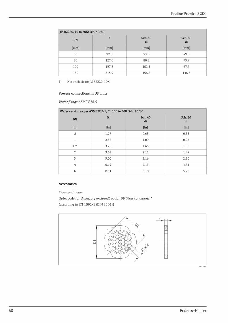
Proline Prowirl D 200
60 Endress+Hauser
JIS B2220, 10 to 20K: Sch. 40/80
DN K Sch. 40di
Sch. 80di
[mm] [mm] [mm] [mm]
50 92.0 53.5 49.3
80 127.0 80.3 73.7
100 157.2 102.3 97.2
150 215.9 156.8 146.3
1) Not available for JIS B2220, 10K
Process connections in US units
Wafer flange ASME B16.5
Wafer version as per ASME B16.5, Cl. 150 to 300: Sch. 40/80
DN K Sch. 40di
Sch. 80di
[in] [in] [in] [in]
½ 1.77 0.65 0.55
1 2.52 1.09 0.96
1 ½ 3.23 1.65 1.50
2 3.62 2.11 1.94
3 5.00 3.16 2.90
4 6.19 4.13 3.83
6 8.51 6.18 5.76
Accessories
Flow conditioner
Order code for "Accessory enclosed", option PF "Flow conditioner"
(according to EN 1092-1 (DIN 2501))
s
D2
D1
35 x
s" "
A0001941

Proline Prowirl D 200
Endress+Hauser 61
Dimensions in SI units
DN[mm]
Pressure rating Centering diameter[mm]
D1 1) / D2 2) s[mm]
15 PN 10 to 40 54.3 D2 2.0
25 PN 10 to 40 74.3 D1 3.5
40 PN 10 to 40 95.3 D1 5.3
50 PN 10 to 40 110.0 D2 6.8
80 PN 10 to 40 145.3 D2 10.1
100 PN 10/16PN 25/40
165.3171.3
D2D1
13.3
150 PN 10/16PN 25/40
221.0227.0
D2D2
20.0
1) The flow conditioner is fitted at the outer diameter between the bolts.2) The flow conditioner is fitted at the indentations between the bolts.
DN[mm]
Pressure rating Centering diameter[mm]
D1 1) / D2 2) s[mm]
15 Class 150Class 300
50.156.5
D1D1
2.0
25 Class 150Class 300
69.274.3
D2D1
3.5
40 Class 150Class 300
88.297.7
D2D2
5.3
50 Class 150Class 300
106.6113.0
D2D1
6.8
80 Class 150Class 300
138.4151.3
D1D1
10.1
100 Class 150Class 300
176.5182.6
D2D1
13.3
150 Class 150Class 300
223.5252.0
D1D1
20.0
1) The flow conditioner is fitted at the outer diameter between the bolts.2) The flow conditioner is fitted at the indentations between the bolts.
DN[mm]
Pressure rating Centering diameter[mm]
D1 1) / D2 2) s[mm]
15 10 K20 K
60.360.3
D2D2
2.0
25 10 K20 K
76.376.3
D2D2
3.5
40 10 K20 K
91.391.3
D2D2
5.3
50 10 K20 K
106.6106.6
D2D2
6.8
80 10 K20 K
136.3142.3
D2D1
10.1
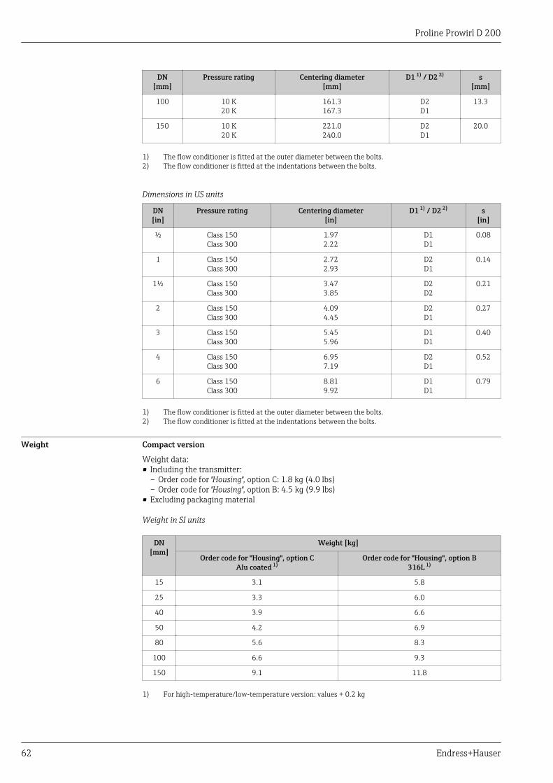
Proline Prowirl D 200
62 Endress+Hauser
DN[mm]
Pressure rating Centering diameter[mm]
D1 1) / D2 2) s[mm]
100 10 K20 K
161.3167.3
D2D1
13.3
150 10 K20 K
221.0240.0
D2D1
20.0
1) The flow conditioner is fitted at the outer diameter between the bolts.2) The flow conditioner is fitted at the indentations between the bolts.
Dimensions in US units
DN[in]
Pressure rating Centering diameter[in]
D1 1) / D2 2) s[in]
½ Class 150Class 300
1.972.22
D1D1
0.08
1 Class 150Class 300
2.722.93
D2D1
0.14
1½ Class 150Class 300
3.473.85
D2D2
0.21
2 Class 150Class 300
4.094.45
D2D1
0.27
3 Class 150Class 300
5.455.96
D1D1
0.40
4 Class 150Class 300
6.957.19
D2D1
0.52
6 Class 150Class 300
8.819.92
D1D1
0.79
1) The flow conditioner is fitted at the outer diameter between the bolts.2) The flow conditioner is fitted at the indentations between the bolts.
Weight Compact version
Weight data:• Including the transmitter:
– Order code for "Housing", option C: 1.8 kg (4.0 lbs)– Order code for "Housing", option B: 4.5 kg (9.9 lbs)
• Excluding packaging material
Weight in SI units
DN[mm]
Weight [kg]
Order code for "Housing", option CAlu coated 1)
Order code for "Housing", option B316L 1)
15 3.1 5.8
25 3.3 6.0
40 3.9 6.6
50 4.2 6.9
80 5.6 8.3
100 6.6 9.3
150 9.1 11.8
1) For high-temperature/low-temperature version: values + 0.2 kg

Proline Prowirl D 200
Endress+Hauser 63
Weight in US units
DN[in]
Weight [lbs]
Order code for "Housing", option CAlu coated 1)
Order code for "Housing", option B316L 1)
½ 6.9 12.9
1 7.4 13.3
1½ 8.7 14.6
2 9.4 15.3
3 12.4 18.4
4 14.6 20.6
6 20.2 26.1
1) For high-temperature/low-temperature version: values +0.4 lbs
Transmitter remote version
Wall-mount housing
Depends on the material of the wall-mount housing:• Aluminum AlSi 10Mg: 2.4 kg (5.2 lb)• Stainless steel 1.4404 (316L): 6.0 kg (13.2 lb)
Sensor remote version
Weight data:• Including the connection housing:
– 0.8 kg (1.8 lbs)– 2.0 kg (4.4 lbs)
• Excluding the connecting cable• Excluding packaging material
Weight in SI units
DN[mm]
Weight [kg]
Order code for "Housing", option CAlu coated 1)
Order code for "Housing", option B316L 1)
15 2.1 3.3
25 2.3 3.5
40 2.9 4.1
50 3.2 4.4
80 4.6 5.8
100 5.6 6.8
150 8.1 9.3
1) For high-temperature/low-temperature version: values + 0.2 kg
Weight in US units
DN[in]
Weight [lbs]
Order code for "Housing", option CAlu coated 1)
Order code for "Housing", option B316L 1)
½ 4.5 7.3
1 5.0 7.8
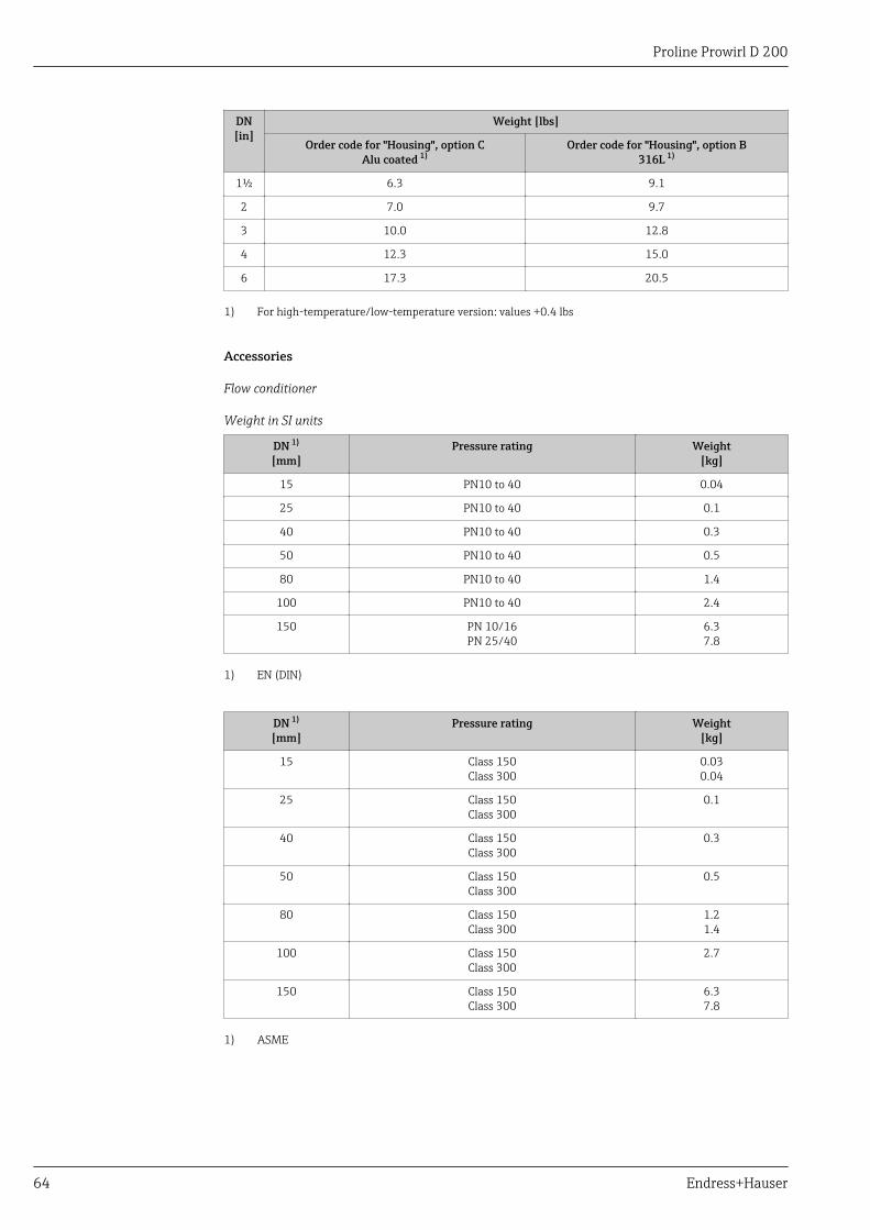
Proline Prowirl D 200
64 Endress+Hauser
DN[in]
Weight [lbs]
Order code for "Housing", option CAlu coated 1)
Order code for "Housing", option B316L 1)
1½ 6.3 9.1
2 7.0 9.7
3 10.0 12.8
4 12.3 15.0
6 17.3 20.5
1) For high-temperature/low-temperature version: values +0.4 lbs
Accessories
Flow conditioner
Weight in SI units
DN 1)
[mm]Pressure rating Weight
[kg]
15 PN10 to 40 0.04
25 PN10 to 40 0.1
40 PN10 to 40 0.3
50 PN10 to 40 0.5
80 PN10 to 40 1.4
100 PN10 to 40 2.4
150 PN 10/16PN 25/40
6.37.8
1) EN (DIN)
DN 1)
[mm]Pressure rating Weight
[kg]
15 Class 150Class 300
0.030.04
25 Class 150Class 300
0.1
40 Class 150Class 300
0.3
50 Class 150Class 300
0.5
80 Class 150Class 300
1.21.4
100 Class 150Class 300
2.7
150 Class 150Class 300
6.37.8
1) ASME

Proline Prowirl D 200
Endress+Hauser 65
DN 1)
[mm]Pressure rating Weight
[kg]
15 10K20K
0.06
25 10K20K
0.1
40 10K20K
0.3
50 10K20K
0.5
80 10K20K
1.1
100 10K20K
1.8
150 10K20K
4.55.5
1) JIS
Weight in US units
DN 1)
[in]Pressure rating Weight
[lbs]
½ Class 150Class 300
0.10.1
1 Class 150Class 300
0.3
1½ Class 150Class 300
0.7
2 Class 150Class 300
1.1
3 Class 150Class 300
2.63.1
4 Class 150Class 300
6.0
6 Class 150Class 300
14.016.0
1) ASME
Materials Transmitter housing
Compact version• Order code for "Housing", option C "Compact, aluminum coated":
Coated aluminum AlSi10Mg• Order code for "Housing", option B "Compact, stainless":
For maximum corrosion resistance: stainless steel 1.4404 (316L)Remote version• Order code for "Housing", option J "Remote, aluminum coated":
Coated aluminum AlSi10Mg• Order code for "Housing", option K "Remote, stainless":
For maximum corrosion resistance: stainless steel 1.4404 (316L)
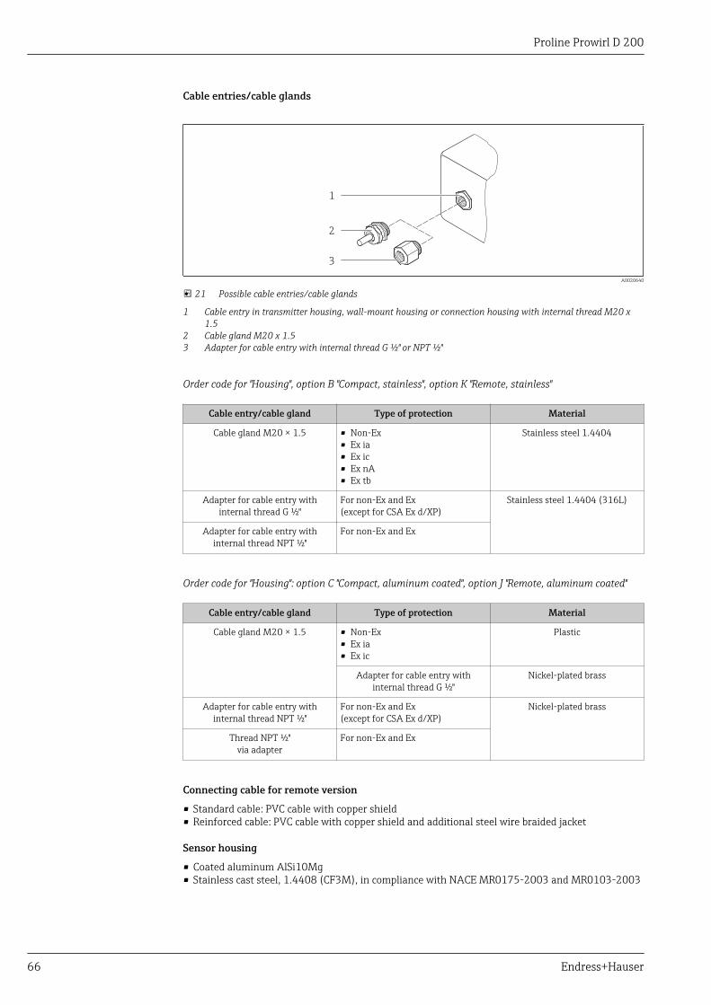
Proline Prowirl D 200
66 Endress+Hauser
Cable entries/cable glands
1
2
3
A0020640
21 Possible cable entries/cable glands
1 Cable entry in transmitter housing, wall-mount housing or connection housing with internal thread M20 x1.5
2 Cable gland M20 x 1.53 Adapter for cable entry with internal thread G ½" or NPT ½"
Order code for "Housing", option B "Compact, stainless", option K "Remote, stainless"
Cable entry/cable gland Type of protection Material
Cable gland M20 × 1.5 • Non-Ex• Ex ia• Ex ic• Ex nA• Ex tb
Stainless steel 1.4404
Adapter for cable entry withinternal thread G ½"
For non-Ex and Ex(except for CSA Ex d/XP)
Stainless steel 1.4404 (316L)
Adapter for cable entry withinternal thread NPT ½"
For non-Ex and Ex
Order code for "Housing": option C "Compact, aluminum coated", option J "Remote, aluminum coated"
Cable entry/cable gland Type of protection Material
Cable gland M20 × 1.5 • Non-Ex• Ex ia• Ex ic
Plastic
Adapter for cable entry withinternal thread G ½"
Nickel-plated brass
Adapter for cable entry withinternal thread NPT ½"
For non-Ex and Ex(except for CSA Ex d/XP)
Nickel-plated brass
Thread NPT ½"via adapter
For non-Ex and Ex
Connecting cable for remote version
• Standard cable: PVC cable with copper shield• Reinforced cable: PVC cable with copper shield and additional steel wire braided jacket
Sensor housing
• Coated aluminum AlSi10Mg• Stainless cast steel, 1.4408 (CF3M), in compliance with NACE MR0175-2003 and MR0103-2003

Proline Prowirl D 200
Endress+Hauser 67
Measuring tubes
Pressure ratings up to PN 40, Class 150/300, and JIS 10K/20K:Stainless cast steel, 1.4408 (CF3M), in compliance with AD2000 (for AD2000 the temperaturerange is limited to –10 to +400 °C (+14 to +752 °F) ) and in compliance with NACE MR0175-2003and MR0103-2003
DSC sensor
Pressure ratings up to PN 40, Class 150/300, and JIS 10K/20K:
Parts in contact with medium (marked as "wet" on the DSC sensor flange):Stainless steel, 1.4435 (316, 316L), in compliance with NACE MR0175-2003 and MR0103-2003Parts not in contact with medium:• Stainless steel 1.4301 (304)• Order code for "Sensor option", option CD "Harsh environment, DSC sensor, sensor components Alloy
C22":Alloy C22 sensor: UNS N06022 similar to Alloy C22/2.4602, in compliance with NACEMR0175-2003 and MR0103-2003
Seals
• Graphite (standard)Pressure rating PN 10 to 40, Class 150 to 300, JIS 10 to 20K: Sigraflex Foil Z (BAM-certified foroxygen applications)
• FPM (Viton)• Kalrez 6375• Gylon 3504 (BAM-certified for oxygen applications, "high quality in terms of TA Luft (German
Clean Air Act"))
Housing support
Stainless steel, 1.4408 (CF3M)
Accessories
Weather protection cover
Stainless steel 1.4301
Flow conditioner
Stainless steel, multiple certifications, 1.4404 (316, 316L), in compliance with NACE MR0175-2003and MR0103-2003
Operability
Operating concept Operator-oriented menu structure for user-specific tasks• Commissioning• Operation• Diagnostics• Expert levelQuick and safe commissioning• Guided menus ("Make-it-run" wizards) for applications• Menu guidance with brief explanations of the individual parameter functions

Proline Prowirl D 200
68 Endress+Hauser
Reliable operation• Operation in the following languages:
– Via local display:English, German, French, Spanish, Italian, Dutch, Portuguese, Polish, Russian, Swedish, Turkish,Chinese, Japanese, Korean, Bahasa (Indonesian), Vietnamese, Czech
– Via "FieldCare" operating tool:English, German, French, Spanish, Italian, Chinese, Japanese
• Uniform operating philosophy applied to device and operating tools• If replacing the electronic module, transfer the device configuration via the integrated memory
(integrated HistoROM) which contains the process and measuring device data and the eventlogbook. No need to reconfigure.
Efficient diagnostics increase measurement availability• Troubleshooting measures can be called up via the device and in the operating tools• Diverse simulation options, logbook for events that occur and optional line recorder functions
Local operation Via display module
Order code for "Display; Operation", option C "SD02" Order code for "Display; Operation", option E "SD03"
+
E
–
1
A0015544
1
+
E
–
A0015546
1 Operation with pushbuttons 1 Operation with touch control
Display elements• 4-line display• With order code for "Display; operation", option E:
White background lighting; switches to red in event of device errors• Format for displaying measured variables and status variables can be individually configured• Permitted ambient temperature for the display: –20 to +60 °C (–4 to +140 °F)
The readability of the display may be impaired at temperatures outside the temperature range.Operating elements• With order code for "Display; operation", option C:
Local operation with 3 push buttons: , , E
• With order code for "Display; operation", option E:External operation via touch control; 3 optical keys: , , E
• Operating elements also accessible in various hazardous areasAdditional functionality• Data backup function
The device configuration can be saved in the display module.• Data comparison function
The device configuration saved in the display module can be compared to the current deviceconfiguration.
• Data transfer functionThe transmitter configuration can be transmitted to another device using the display module.
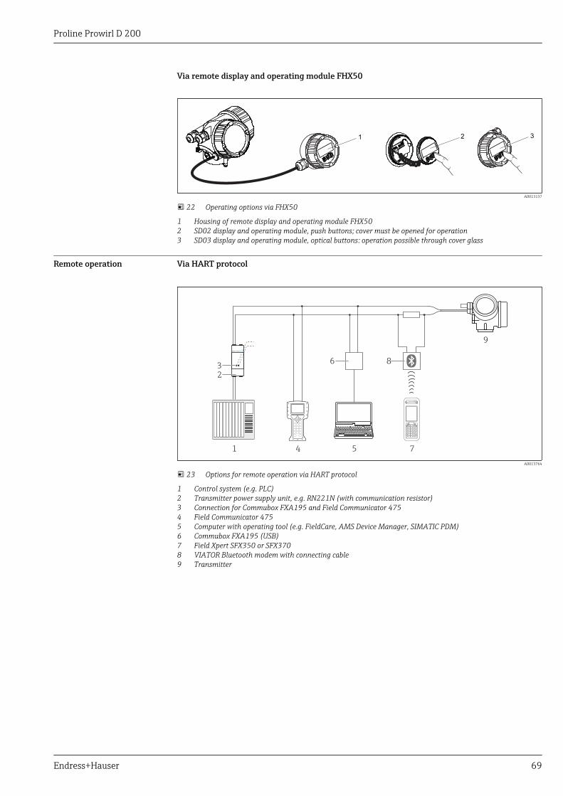
Proline Prowirl D 200
Endress+Hauser 69
Via remote display and operating module FHX50
321
A0013137
22 Operating options via FHX50
1 Housing of remote display and operating module FHX502 SD02 display and operating module, push buttons; cover must be opened for operation3 SD03 display and operating module, optical buttons: operation possible through cover glass
Remote operation Via HART protocol
1
2
4 5 7
9
6 83
A0013764
23 Options for remote operation via HART protocol
1 Control system (e.g. PLC)2 Transmitter power supply unit, e.g. RN221N (with communication resistor)3 Connection for Commubox FXA195 and Field Communicator 4754 Field Communicator 4755 Computer with operating tool (e.g. FieldCare, AMS Device Manager, SIMATIC PDM)6 Commubox FXA195 (USB)7 Field Xpert SFX350 or SFX3708 VIATOR Bluetooth modem with connecting cable9 Transmitter
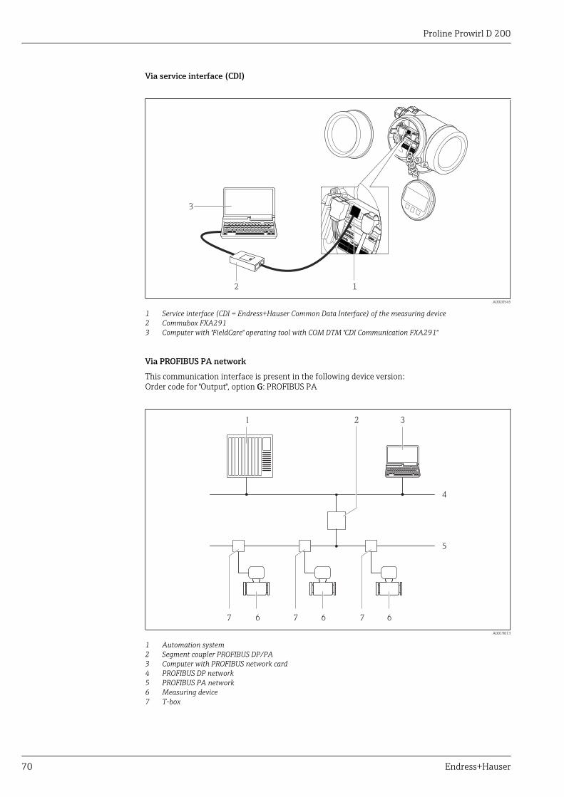
Proline Prowirl D 200
70 Endress+Hauser
Via service interface (CDI)
12
3 +
E
–
A0020545
1 Service interface (CDI = Endress+Hauser Common Data Interface) of the measuring device2 Commubox FXA2913 Computer with "FieldCare" operating tool with COM DTM "CDI Communication FXA291"
Via PROFIBUS PA network
This communication interface is present in the following device version:Order code for "Output", option G: PROFIBUS PA
1 32
4
5
666 777
A0019013
1 Automation system2 Segment coupler PROFIBUS DP/PA3 Computer with PROFIBUS network card4 PROFIBUS DP network5 PROFIBUS PA network6 Measuring device7 T-box

Proline Prowirl D 200
Endress+Hauser 71
Certificates and approvals
CE mark The measuring system is in conformity with the statutory requirements of the applicable ECDirectives. These are listed in the corresponding EC Declaration of Conformity along with thestandards applied.
Endress+Hauser confirms successful testing of the device by affixing to it the CE mark.
C-Tick symbol The measuring system meets the EMC requirements of the "Australian Communications and MediaAuthority (ACMA)".
Ex approval The measuring device is certified for use in hazardous areas and the relevant safety instructions areprovided in the separate "Safety Instructions" (XA) document. Reference is made to this document onthe nameplate.
The separate Ex documentation (XA) containing all the relevant explosion protection data isavailable from your Endress+Hauser sales center.
ATEX, IECEx
Currently, the following versions for use in hazardous areas are available:
Ex d
Category Type of protection
II2G/Zone 1 Ex d[ia] IIC T6…T1
II1/2G/Zone 0/1 Ex d[ia] IIC T6…T1
Ex ia
Category Type of protection
II2G/Zone 1 Ex ia IIC T6…T1
II1G/Zone 0 Ex ia IIC T6…T1
II1/2G/Zone 0/1 Ex ia IIC T6…T1
Ex ic
Category Type of protection
II3G/Zone 2 Ex ic IIC T6…T1
II1/3G/Zone 0/2 Ex ic[ia] IIC T6…T1
Ex nA
Category Type of protection
II3G/Zone 2 Ex nA IIC T6…T1
Ex tb
Category Type of protection
II2D/Zone 21 Ex tb IIIC Txxx

Proline Prowirl D 200
72 Endress+Hauser
cCSAus
Currently, the following versions for use in hazardous areas are available:
XP
Category Type of protection
Class I, II, III Division 1 Groups A-G XP (Ex d Flameproof version)
IS
Category Type of protection
Class I, II, III Division 1 Groups A-G IS (Ex i Intrinsically safe version)
NI
Category Type of protection
Class I Division 2 Groups ABCD NI (Non-incentive version), NIFW-Parameter*
*= Entity- und NIFW-Parameter gemäß Control Drawings
NEPSI
Currently, the following versions for use in hazardous areas are available:
Ex d
Category Type of protection
Zone 1 Ex d[ia] IIC T1 ~ T6Ex d[ia Ga] IIC T1 ~ T6
Zone 0/1 Ex d[ia] IIC T1 ~ T6 DIP A21Ex d[ia Ga] IIC T1 ~ T6 DIP A21
Ex ia
Category Type of protection
Zone 1 Ex ia IIC T1 ~ T6
Zone 0/1 Ex ia IIC T1 ~ T6 DIP A21
Ex ic
Category Type of protection
II3G/Zone 2 Ex ic IIC T1 ~ T6
II1/3G/Zone 0/2 Ex ic[ia Ga] IIC T1 ~ T6
Ex nA
Category Type of protection
Zone 2 Ex nA IIC T1 ~ T6Ex nA[ia Ga] IIC T1 ~ T6

Proline Prowirl D 200
Endress+Hauser 73
INMETRO
Currently, the following versions for use in hazardous areas are available:
Ex d
Category Type of protection
– Ex d[ia] IIC T6…T1
Ex ia
Category Type of protection
– Ex ia IIC T6…T1
Ex nA
Category Type of protection
– Ex nA IIC T6…T1Ex nA[ia Ga] IIC T6…T1
Functional safety The measuring device can be used for flow monitoring systems (min., max., range) up to SIL 2(single-channel architecture) and SIL 3 (multichannel architecture with homogeneous redundancy)and is independently evaluated and certified by the TÜV in accordance with IEC 61508.
The following types of monitoring in safety equipment are possible:Volume flow
Functional Safety Manual with information on the SIL device (→ 79)
Certification PROFIBUS PROFIBUS interface
The measuring device is certified and registered by the PROFIBUS User Organization (PNO). Themeasuring system meets all the requirements of the following specifications:• Certified in accordance with PROFIBUS PA Profile 3.02• The device can also be operated with certified devices of other manufacturers (interoperability)
Pressure EquipmentDirective
• With the PED/G1/x (x = category) marking on the sensor nameplate, Endress+Hauser confirmscompliance with the "Essential Safety Requirements" specified in Annex I of the PressureEquipment Directive 97/23/EC.
• Devices bearing this marking (PED) are suitable for the following types of medium:Media in Group 1 and 2 with a vapor pressure greater than, or smaller and equalto0.5 bar (7.3 psi)
• Devices not bearing this marking (PED) are designed and manufactured according to goodengineering practice. They meet the requirements of Art.3 Section 3 of the Pressure EquipmentDirective 97/23/EC. The range of application is indicated in tables 6 to 9 in Annex II of thePressure Equipment Directive.
Other standards andguidelines
• EN 60529Degrees of protection by housing (IP code)
• DIN ISO 13359Measurement of conductive liquid flow in closed conduits - Flanged-type electromagneticflowmeters - Overall length
• EN 61010-1Protection Measures for Electrical Equipment for Measurement, Control, Regulation andLaboratory Procedures.
• IEC/EN 61326Emission in accordance with Class A requirements. Electromagnetic compatibility (EMCrequirements)
• NAMUR NE 21Electromagnetic compatibility (EMC) of industrial process and laboratory control equipment.
• NAMUR NE 32Data Retention in the Event of a Power Failure in Field and Control Instruments withMicroprocessors

Proline Prowirl D 200
74 Endress+Hauser
• NAMUR NE 43Standardization of the signal level for the breakdown information of digital transmitters withanalog output signal.
• NAMUR NE 53Software of field devices and signal-processing devices with digital electronics
• NAMUR NE 105Specifications for Integrating Fieldbus Devices in Engineering Tools for Field Devices
• NAMUR NE 107Self-monitoring and diagnosis of field devices
• NAMUR NE 131Requirements for field devices for standard applications
• ASME BPVC Section VIII, Division 1Rules for Construction of Pressure Vessels
Ordering informationDetailed ordering information is available from the following sources:• In the Product Configurator on the Endress+Hauser website: www.endress.com → Select country →
Instruments → Select device → Product page function: Configure this product• From your Endress+Hauser Sales Center: www.endress.com/worldwide
Product Configurator - the tool for individual product configuration• Up-to-the-minute configuration data• Depending on the device: Direct input of measuring point-specific information such as
measuring range or operating language• Automatic verification of exclusion criteria• Automatic creation of the order code and its breakdown in PDF or Excel output format• Ability to order directly in the Endress+Hauser Online Shop
Application packagesMany different application packages are available to enhance the functionality of the device. Suchpackages might be needed to address safety aspects or specific application requirements.
The application packages can be ordered from Endress+Hauser either directly with the device orsubsequently. Detailed information on the order code in question is available from your local Endress+Hauser sales center or on the product page of the Endress+Hauser website: www.endress.com.
For detailed information on the application packages, see the Special Documentation for thedevice (→ 79)
Diagnostics functions Package Description
HistoROM extendedfunction
Comprises extended functions concerning the event log and the activation of themeasured value memory.
Event log:Memory volume is extended from 20 message entries (basic version) to up to 100entries.
Data logging (line recorder):• Memory capacity for up to 1000 measured values is activated.• 250 measured values can be output via each of the 4 memory channels. The
recording interval can be defined and configured by the user.• Data logging is visualized via the local display or FieldCare.
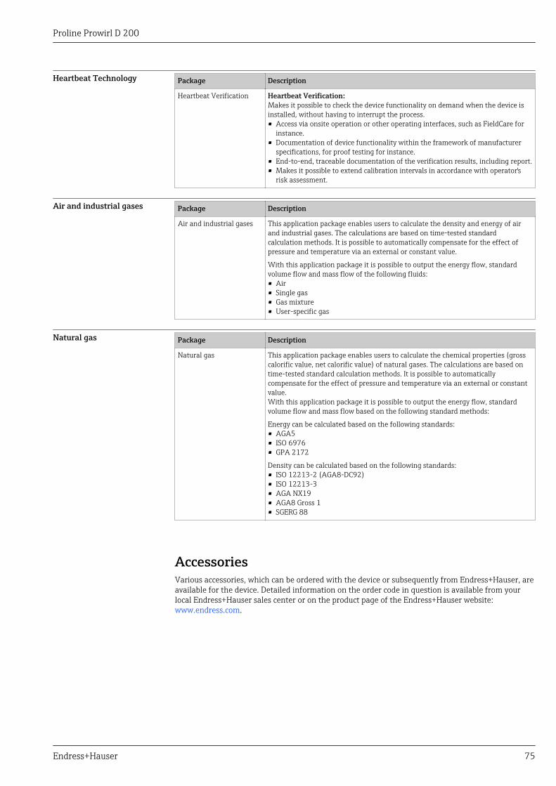
Proline Prowirl D 200
Endress+Hauser 75
Heartbeat Technology Package Description
Heartbeat Verification Heartbeat Verification:Makes it possible to check the device functionality on demand when the device isinstalled, without having to interrupt the process.• Access via onsite operation or other operating interfaces, such as FieldCare for
instance.• Documentation of device functionality within the framework of manufacturer
specifications, for proof testing for instance.• End-to-end, traceable documentation of the verification results, including report.• Makes it possible to extend calibration intervals in accordance with operator's
risk assessment.
Air and industrial gases Package Description
Air and industrial gases This application package enables users to calculate the density and energy of airand industrial gases. The calculations are based on time-tested standardcalculation methods. It is possible to automatically compensate for the effect ofpressure and temperature via an external or constant value.
With this application package it is possible to output the energy flow, standardvolume flow and mass flow of the following fluids:• Air• Single gas• Gas mixture• User-specific gas
Natural gas Package Description
Natural gas This application package enables users to calculate the chemical properties (grosscalorific value, net calorific value) of natural gases. The calculations are based ontime-tested standard calculation methods. It is possible to automaticallycompensate for the effect of pressure and temperature via an external or constantvalue.With this application package it is possible to output the energy flow, standardvolume flow and mass flow based on the following standard methods:
Energy can be calculated based on the following standards:• AGA5• ISO 6976• GPA 2172
Density can be calculated based on the following standards:• ISO 12213-2 (AGA8-DC92)• ISO 12213-3• AGA NX19• AGA8 Gross 1• SGERG 88
AccessoriesVarious accessories, which can be ordered with the device or subsequently from Endress+Hauser, areavailable for the device. Detailed information on the order code in question is available from yourlocal Endress+Hauser sales center or on the product page of the Endress+Hauser website:www.endress.com.

Proline Prowirl D 200
76 Endress+Hauser
Device-specific accessories For the transmitter
Accessories Description
Prowirl 200 transmitter Transmitter for replacement or for stock. Use the order code to define the followingspecifications:• Approvals• Output• Display / operation• Housing• Software
For details, see Installation Instructions EA01056D
Remote displayFHX50
FHX50 housing to accommodate a display module (→ 69).
• FHX50 housing suitable for:– SD02 display module (push buttons)– SD03 display module (touch control)
• Housing material:– Plastic PBT– 316L
• Length of connecting cable: up to max. 60 m (196 ft)(cable lengths available for order: 5 m (16 ft), 10 m (32 ft), 20 m (65 ft),30 m (98 ft))
The measuring device can be ordered with the FHX50 housing and a displaymodule. The following options must be selected in the separate order codes:• Order code for measuring device, feature 030:
Option L or M "Prepared for FHX50 display"• Order code for FHX50 housing, feature 050 (device version):
Option A "Prepared for FHX50 display"• Order code for FHX50 housing, depends on the desired display module in feature
020 (display, operation):– Option C: for an SD02 display module (push buttons)– Option E: for an SD03 display module (touch control)
The FHX50 housing can also be ordered as a retrofit kit. The measuring devicedisplay module is used in the FHX50 housing. The following options must beselected in the order code for the FHX50 housing:• Feature 050 (measuring device version): option B "Not prepared for FHX50
display"• Feature 020 (display, operation): option A "None, existing displayed used"
For details, see Special Documentation SD01007F
Overvoltage protection for2-wire devices
Ideally, the overvoltage protection module should be ordered directly with thedevice. See product structure, characteristic 610 "Accessory mounted", option NA"Overvoltage protection". Separate order necessary only if retrofitting.
• OVP10: For 1-channel devices (characteristic 020, option A):• OVP20: For 2-channel devices (characteristic 020, options B, C, E or G)
For details, see Special Documentation SD01090F.
Weather protection cover Is used to protect the measuring device from the effects of the weather: e.g.rainwater, excess heating from direct sunlight or extreme cold in winter.
For details, see Special Documentation SD00333F
Connecting cable forremote version
• Connecting cable available in various lengths:– 5 m (16 ft)– 10 m (32 ft)– 20 m (65 ft)– 30 m (98 ft)
• Reinforced cables available on request.
Post mounting kit Post mounting kit for transmitter.
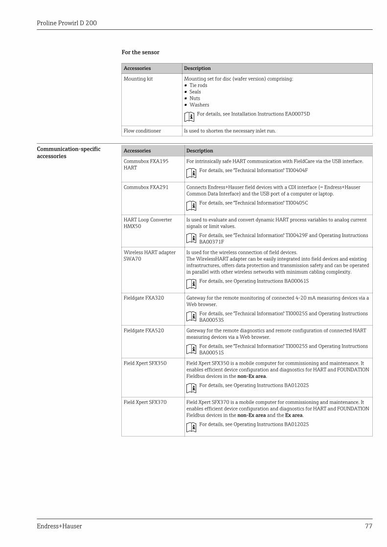
Proline Prowirl D 200
Endress+Hauser 77
For the sensor
Accessories Description
Mounting kit Mounting set for disc (wafer version) comprising:• Tie rods• Seals• Nuts• Washers
For details, see Installation Instructions EA00075D
Flow conditioner Is used to shorten the necessary inlet run.
Communication-specificaccessories
Accessories Description
Commubox FXA195HART
For intrinsically safe HART communication with FieldCare via the USB interface.
For details, see "Technical Information" TI00404F
Commubox FXA291 Connects Endress+Hauser field devices with a CDI interface (= Endress+HauserCommon Data Interface) and the USB port of a computer or laptop.
For details, see "Technical Information" TI00405C
HART Loop ConverterHMX50
Is used to evaluate and convert dynamic HART process variables to analog currentsignals or limit values.
For details, see "Technical Information" TI00429F and Operating InstructionsBA00371F
Wireless HART adapterSWA70
Is used for the wireless connection of field devices.The WirelessHART adapter can be easily integrated into field devices and existinginfrastructures, offers data protection and transmission safety and can be operatedin parallel with other wireless networks with minimum cabling complexity.
For details, see Operating Instructions BA00061S
Fieldgate FXA320 Gateway for the remote monitoring of connected 4-20 mA measuring devices via aWeb browser.
For details, see "Technical Information" TI00025S and Operating InstructionsBA00053S
Fieldgate FXA520 Gateway for the remote diagnostics and remote configuration of connected HARTmeasuring devices via a Web browser.
For details, see "Technical Information" TI00025S and Operating InstructionsBA00051S
Field Xpert SFX350 Field Xpert SFX350 is a mobile computer for commissioning and maintenance. Itenables efficient device configuration and diagnostics for HART and FOUNDATIONFieldbus devices in the non-Ex area.
For details, see Operating Instructions BA01202S
Field Xpert SFX370 Field Xpert SFX370 is a mobile computer for commissioning and maintenance. Itenables efficient device configuration and diagnostics for HART and FOUNDATIONFieldbus devices in the non-Ex area and the Ex area.
For details, see Operating Instructions BA01202S

Proline Prowirl D 200
78 Endress+Hauser
Service-specific accessories Accessories Description
Applicator Software for selecting and sizing Endress+Hauser measuring devices:• Calculation of all the necessary data for identifying the optimum flowmeter: e.g.
nominal diameter, pressure loss, accuracy or process connections.• Graphic illustration of the calculation results
Administration, documentation and access to all project-related data andparameters over the entire life cycle of a project.
Applicator is available:• Via the Internet: https://wapps.endress.com/applicator• On CD-ROM for local PC installation.
W@M Life cycle management for your plantW@M supports you with a wide range of software applications over the entireprocess: from planning and procurement, to the installation, commissioning andoperation of the measuring devices. All the relevant device information, such asthe device status, spare parts and device-specific documentation, is available forevery device over the entire life cycle.The application already contains the data of your Endress+Hauser device. Endress+Hauser also takes care of maintaining and updating the data records.
W@M is available:• Via the Internet: www.endress.com/lifecyclemanagement• On CD-ROM for local PC installation.
FieldCare FDT-based plant asset management tool from Endress+Hauser.It can configure all smart field units in your system and helps you manage them. Byusing the status information, it is also a simple but effective way of checking theirstatus and condition.
For details, see Operating Instructions BA00027S and BA00059S
System components Accessories Description
Memograph M graphicdisplay recorder
The Memograph M graphic display recorder provides information on all relevantmeasured variables. Measured values are recorded correctly, limit values aremonitored and measuring points analyzed. The data are stored in the 256 MBinternal memory and also on a SD card or USB stick.
For details, see "Technical Information" TI00133R and Operating InstructionsBA00247R
RN221N Active barrier with power supply for safe separation of 4-20 mA standard signalcircuits. Offers bidirectional HART transmission.
For details, see "Technical Information" TI00073R and Operating InstructionsBA00202R
RNS221 Supply unit for powering two 2-wire measuring devices solely in the non-Ex area.Bidirectional communication is possible via the HART communication jacks.
For details, see "Technical Information" TI00081R and Brief OperatingInstructions KA00110R
Cerabar M The pressure transmitter for measuring the absolute and gauge pressure of gases,steam and liquids. It can be used to read in the operating pressure value.
For details, see "Technical Information" TI00426P, TI00436P and OperatingInstructions BA00200P, BA00382P
Cerabar S The pressure transmitter for measuring the absolute and gauge pressure of gases,steam and liquids. It can be used to read in the operating pressure value.
For details, see "Technical Information" TI00383P and Operating InstructionsBA00271P

Proline Prowirl D 200
Endress+Hauser 79
DocumentationFor an overview of the scope of the associated Technical Documentation, refer to the following:• The CD-ROM provided for the device (depending on the device version, the CD-ROM might
not be part of the delivery!)• The W@M Device Viewer : Enter the serial number from the nameplate
(www.endress.com/deviceviewer)• The Endress+Hauser Operations App: Enter the serial number from the nameplate or scan the
2-D matrix code (QR code) on the nameplate.
Standard documentation Brief Operating Instructions
Measuring device Documentation code
Prowirl D 200 KA01135D
Operating Instructions
Measuring device Documentation code
HART FOUNDATION Fieldbus PROFIBUS PA
Prowirl D 200 BA01153D BA01216D BA01221D
Supplementary device-dependent documentation Safety Instructions
Contents Documentation code
ATEX/IECEx Ex d, Ex tb XA01148D
ATEX/IECEx Ex ia, Ex tb XA01151D
ATEX/IECEx Ex ic, Ex nA XA01152D
CCSAUS XP XA01153D
CCSAUS IS XA01154D
NEPSI Ex d XA01238D
NEPSI Ex i XA01239D
NEPSI Ex ic, Ex nA XA01240D
INMETRO Ex d XA01250D
INMETRO Ex i XA01042D
INMETRO Ex nA XA01043D
Special Documentation
Contents Documentation code
Information on the Pressure Equipment Directive SD01163D
Functional Safety Manual SD01162D
Heartbeat Technology SD01204D
Natural gas SD01194D
Air + Industrial Gases (Single Gas + Gas Mixtures) SD01195D
Installation Instructions
Contents Documentation code
Installation Instructions for spare part sets Specified for each individual accessory (→ 76)

Proline Prowirl D 200
Registered trademarksHART®
Registered trademark of the HART Communication Foundation, Austin, USA
PROFIBUS®
Registered trademark of the PROFIBUS User Organization, Karlsruhe, Germany
KALREZ ®, VITON ®Registered trademarks of DuPont Performance Elastomers L.L.C., Wilmington, DE USA
GYLON®
Registered trademark of Garlock Sealing Technologies, Palmyar, NY, USA
Applicator®, FieldCare®, Field XpertTM, HistoROM®, Heartbeat TechnologyTM
Registered or registration-pending trademarks of the Endress+Hauser Group
www.addresses.endress.com