promatect ® 100 fittingly also takes a proactive approach to environmental, health and safety...
TRANSCRIPT


.

General information and
introduction on PROMATECT® 100
An Introduction to PROMATECT® 100 Fire Rated Systems _________________ 2
Principles of ‘Proactive Fire Protection’ __________________________________ 5
Physical Properties _____________________________________________________ 7
Fabrication of Board System ____________________________________________ 8
PROMATECT® 100
Structural Steel Protection
General Information/Definition &
Calculation for Section Factor __________________________________________ 16
Calculation of Hp/A Values _____________________________________________ 18
Hp/A Tables for Steel Work Encasement ________________________________ 19
Column Cladding ______________________________________________________ 30
Beam Cladding ________________________________________________________ 31
PROMATECT® 100
Partitions Systems
Index of PROMATECT® 100 Partition Systems ___________________________ 35
General Information ___________________________________________________ 36
Acoustic Design _______________________________________________________ 41
Steel Stud Partition ____________________________________________________ 43
Timber Stud Partition __________________________________________________ 54
Solid/Frameless Internal Partition ______________________________________ 58
PROMATECT® 100
Ceilings & Floors Systems
Index of PROMATECT® 100 Ceilings & Floors Systems ___________________ 62
General Information ___________________________________________________ 64
Self-supporting Ceiling Membrane ______________________________________ 68
Timber Floor Protection ________________________________________________ 74
Mezzanine Floor _______________________________________________________ 79
Penetration &
Perimeter Detailing
Steel Stud Partitions Window & Door Framings __________________________ 83
Steel Stud Partitions Typical Deflectionad Head Details __________________ 84
Steel Stud Partitions Base Details ______________________________________ 85
Steel/Timber Stud Partitions Movement Joints Details ___________________ 86
Steel Stud Partitions Junction Details ___________________________________ 87
Solid/Frameless Partitions Connection Details __________________________ 89
Ceiling Perimeter Details _______________________________________________ 90
Ceilings Control Joints Details __________________________________________ 92
Penetration Seals ______________________________________________________ 93
Access Hatches _______________________________________________________ 95
FAQs and Promat Systems
in Australia
FAQs and Promat Systems in Australia __________________________________ 97
Contents

Information
How to use the PROMATECT® 100 Handbook
System Table Guide
Chapter 1: Introduction & General Information of Promatect® 100
Chapter 2: Promatect® 100 Structural Steel Protection
Chapter 3: PROMATECT® 100 Partition Systems
Chapter 4: PROMATECT® 100 Ceiling & Floor Systems
Chapter 5: Penetrations & Perimeter Detailing
Chapter 6: FAQs & Promat Systems in Australia
System drawing
System installation drawing
System specification
Architectural specification
System and
component detail
System construction detail
Sound Transmission
Class (STC) range for
illustrated system
Fire resistance level,
standard & approvals
Acoustic table
System indication
and system code
Chapter 1:
Introduction &
General Information
of Promatect® 100An Introduction to PROMATECT® 100 Fire Rated Systems __ 2
Principles of ‘Proactive Fire Protection’ ___________________ 5
Physical Properties ______________________________________ 7
Fabrication of Board System _____________________________ 8
1

2
Introduction
What are autoclaved matrix engineered
mineral boards?
Promat manufactures a number of autoclaved matrix engineered
mineral boards, including PROMATECT®-H and PROMATECT®-L500.
The autoclave process exposes the mixture of raw materials to
elevated temperatures and pressures to create a product with
useful, versatile and beneficial properties:
• Non-combustibility
• Good impact and abrasion resistance
• Moisture tolerance
• Good dimensional stability
• Stability in fire conditions
• Good insulation properties when exposed to fire
The fire insulation properties of Promat’s matrix engineered mineral
boards are mainly due to the presence of a controlled moisture
content held within the board.
PROMATECT®-H is a laminated cementitious board which is
subjected to heat and pressure in an autoclave to form a sturdy,
multi-purpose matrix engineered mineral board.
PROMATECT®-L500 is a monolithic matrix engineered mineral
board formed by pressing together autoclaved calcium silicate
spheres called PROMAXON®.
PROMATECT® 100, in fact, is a hybrid development of matrix
engineered mineral and gypsum technology using PROMAXON®,
providing the following performance enhancements:
• Superior insulation properties when exposed to fire
• Excellent workability - easy to cut
• Smooth and flat surface
• High flexural strength providing the ability to form curved linings
• Cost efficient
Improved fire insulation
The composition of the new PROMATECT® 100 board contains a
key component which improves the fire insulation of the product,
thanks to an endothermic process which produces a chemical
change accompanied by the absorption of heat.
The critically important component is autoclaved matrix engineered
mineral spheres (also known as PROMAXON®) bound in a mineral
matrix. It is PROMAXON® in combination with the mineral matrix
that eventually creates the endothermic process when exposed
to fire.
The end result is significantly better fire insulation than that
provided by either traditional matrix engineered mineral boards or
gypsum boards. The new PROMATECT® 100 boards have both a
small amount of free water in the PROMAXON® and chemically-
bound water in the mineral matrix. By producing more water and
retaining it longer within the board, fire insulation is improved.
What exactly is PROMAXON® and how
does it contribute to board performance?
PROMAXON® is a synthetic hydrated matrix engineered mineral in
spherical form. The outer shell of close-knit micropores forms the
linking network for the mineral matrix of the PROMATECT® 100
board. This is a key factor in the board’s cohesion and stability in
fire conditions. A mineral additive acts as filler in the gaps between
the spherical PROMAXON® particles.
In fire, the release of free water within the board, and then the
chemically-bound water from the mineral matrix, cause a cooling
effect which reduces the temperature rise on the non-fire side of the
board. However, before the water can escape from the board, the
PROMAXON® spheres recapture part of the water that has been
released. This then creates a further endothermic process that
gradually releases the recaptured water molecules, thus creating a
further drop in the rate of temperature rise.
In the application of PROMAXON® technology and the development
of PROMATECT® 100, Promat have created a new generation
of boards which combine the advantages of traditionally
manufactured matrix engineered mineral and gypsum boards with
other outstanding advantages.
The Mineral and Matrix Engineering technology.
Benefits of PROMATECT® 100
• Single layer constructions for steel stud partitions
• Speed of installation
• Proven cost effective lightweight drywall systems
• Lowest wall section ‘footprint’
• Installation by carpentry trades
• High quality finishes
• Readily availablity

3
Promat
Environmental
Health & Safety
(EHS) Policy And
Other Related
Developments
Promat International Asia Pacific is one of the main subsidiaries of
Belgium’s Etex Group of companies. Headquartered in Brussels,
Etex consists of some 135 business units across 40 countries,
employing more than 12,500 people worldwide.
As ecologically sustainable issues become increasingly important
and the cause of mounting concern in a rapidly globalising
world, Etex has consistently articulated a well-defined
environmental, health and safety policy as a benchmark for all
its member companies.
Be Green And Protect The Built Environment?
Despite being surrounded by the steel, concrete and glass of
crowded urbanity, Promat realises that Mother Nature will always
hold the key to how we humans live. Coming from cities and
personal, climate-controlled spaces, we frequently tend to
overlook this simple, undeniable fact of life…a fact reconfirmed
time and again.
It has become obvious, to Promat at least, that we have no choice
but to do much, much more for our environment, both directly and
indirectly. Recycling plastic bags and using less fossil fuels for
example, is good but no longer enough. We are inclined to agree
with those who believe that the best chance for society and a
sustainable future is to follow the master plan – plain for all to see
in nature – and actually design a very high level of true recyclability
into everything we do, especially in the structures and built
environment we live and work in. Clearly, a fundamental and broad-
based change of mindset is first essential. In the meantime we have
to start somewhere.
It is noteworthy that Etex Group policies are based on a sound
value system of corporate social responsibility. The Group’s very
own Environment, Health and Safety department is dedicated solely
to environmental, health and safety issues of our factories and
offices, our people and the communities in which we work. In Asia
Pacific, environmental awareness varies, reflecting the different
stages of development and maturity present in the region.
Environmental issues are definitely on the agenda and destined to
generate more significance in the near future.
Our support, adherence to and respect for environmental issues is
highlighted through our membership of the Green Building Council
of Australia. This not-for-profit initiative aims to promote the
transition of building design, construction and operation to
optimum green principles. The same green principles are core
Promat corporate beliefs.
In other Asia Pacific states, plans are well underway to ensure
that all future buildings will address and resolve numerous
environmental concerns. It is good for the building and the
occupants of the building. It is good for the local community and it
is good for the environment. A true win-win situation that can
only get better, improving the quality of life for our children and our
grandchildren and their children.
Environment Management Systems are tools for managing
the impact of an organisation’s activities on the environment.
Certified to the international standard ISO14001, Promat aims
to consolidate environmental gains through the implementation of
effective environmental management. Adherence to this standard
ensures environmental issues are considered within decision
making practices.
We must remain alert and mindful that the future will demand much
more of environmental issues. There will certainly be some daunting
challenges and we will need to continue adapting, as we have done
in the past. Our new production lines in our factories across the
world are a reassuring case in point…there’s very little waste and
we save a lot of energy. We can be environmentally responsible
AND make good business, particularly if we use wisely the
accumulated experience and considerable resources available to
us.
Making the world a better place in which to live and work – for
ourselves and for society as a whole – is always a matter of policy
priority for Promat and the Etex Group of companies as a whole, for
now and for the future.
Committed To Environmental Concerns
As a global leader in the business of the proactive fire protection,
Promat fittingly also takes a proactive approach to environmental,
health and safety issues. Starting in 2005, Promat implemented its
own Environment, Health & Safety policy, entitled “Promat –
Towards Sustainable Growth”.
Promat is therefore committed to:
• the creation of a safe working environment for all its employees
and the societies in which the company works,
• control and minimise potential negative impact
on the environment,
• include EHS concerns in the development of its products
and systems,
• continuous improvement of its EHS performance,
• transparency and open dialogue based on facts and figures
with all its stakeholders,
• the principle that EHS Due Diligence shall be used as
standard practice for Mergers and Acquisitions,
Investments and Divestments.
The policy applies to all Promat entities and necessary resources are
allocated in order to enable correct implementation of its EHS policy.
Before making critical investment or acquisition decisions, the
environmental, health and safety aspect is systematically evaluated.
Accordingly, Promat has developed a checklist which enables the
company to form an accurate overview of the relevant EHS aspects
in a relatively short space of time.
Group Environmental Policies Continually Evolve
It should always be noted, however, that – to be both meaningful
and accurate – realistic environmental policies must continually
evolve. After all, the world around us is constantly changing. A good
reflection of this point of view are the recent additions to the Etex
Group’s EHS policy.
These take a broad view of pertinent ecological issues, along a
time line between 2007 and 2011, while looking at specific
considerations, such as:
• OHSAS certification
• Environmental reporting
• Accident analysis
OHSAS Certification
The Etex Group and Promat are rightly concerned with all matters
related to ISO14001 certification, the universally recognised
certification process for most environmental management concerns.
Now, however, the group insists that all group factories will have to
comply with OHSAS certification. Implementation is expected to
start in 2008 and be completed before 2010.
Although not an international standard, OHSAS Certification –
based on the Occupational Health & Safety Assessment Series –
gains increasing recognition around the world. It is formulated
and implemented on a framework of corporate occupational
health and safety policies, planning, implementation and
operations, checking and corrective action, management reviews
and continual improvement.
Introduction
4
Introduction
Fire Safety In The Building Industry
Like buildings, fire control is a continually evolving science that
generally starts with the idea that a bucket of water or sand in the
right hands at the right time and place can make the difference
between a minor incident and a major disaster. Unfortunately, we
live in a built environment that is considerably more complicated.
The risk of a fire depends on a building’s use, location, size,
occupants, design and construction. In general, the larger the
building, the greater the risk to life and property.
A vital factor in reducing risk is to provide physical barriers to
the spread of fire within the building. This is done by dividing the
building into a series of compartments contained within fire
resisting walls and floors. This fundamentally effective concept is
generally referred to as “compartmentation”. Each compartment,
regardless of penetrations, is fire-proofed to an optimum level to
prevent the spread of fire, smoke and toxic gases.
The protection of the structural frame, the enclosure and protection
of vertical and horizontal openings, effective fire-stopping at
junctions, protection of service penetrations, use of low flame
spread finishing materials and non-combustible materials are all
important considerations.
In addition, the fire performance of external walls and roofs and
their proximity to other buildings are essential factors to consider in
the prevention of spread of fire between buildings.
All these measures are referred to as “proactive” fire protection for
they are systems that do not require power or water to operate in the
event of a fire. They protect on demand, as and when necessary.
“Active” fire protection measures are those that use an integrated
system consisting of sprinklers and alarms that require electricity
and water to realise their full potential in fire situations.
Two other fire design concepts also have significant bearing not
only on fire safety but also architectural and engineering expression.
These are building design according to (1) Prescriptive Building
Codes or (2) Performance-based Building Codes.
Prescriptive Building Codes,
The Orthodox View To Building Fire Safety
Traditionally, most design for fire has been based on prescriptive
building codes by which fire safety is usually achieved by designing
various components in isolation. The building layout must usually
meet certain requirements, such as maximum compartment size
and minimum/maximum dimensions of the exit routes. The building
fabric, structural elements and other building components only
have to meet prescriptive requirements. Any possible interaction
between different fire protection measures is not considered, unless
explicitly allowed as an acceptable trade-off.
Prescriptive approaches in fire design often create problems for
modern buildings with mixed use occupancies, large assembly
areas or unique atrium designs. This is because in the world of
modern building design and construction, a variety of security and
life safety questions are asked of engineers and architects who
must then provide a functional building in which solutions ideally
balance design with the risks associated with any building-
regardless of size and occupancy.
Conversely, compartmentation as described by prescriptive codes
can result in dividing the building into small cubes that limit
architectural expression and effective functioning of the structure.
Furthermore, current building design practice does not consider fire
as a design condition. Instead, structural fire endurance ratings are
prescribed in building codes using standard tests on individual
components and generally do not represent real fire hazards in
modern buildings. Prescriptive approaches also do not consider
the fire performance of structural connections or the structural
system as a whole or the multiple performance demands on fire
proofing materials.
Building codes across the world today are undergoing a major
evolution to address their ability in providing flexibility in the building
and architectural design process and use of a building together with
cost-effective fire and life safety measures.
Performance-based Fire Design,
The Way Of The Future
Undoubtedly, prescriptive local fire and construction codes ensure
that modern buildings are designed to minimise the likelihood of a
major fire. On the other hand however, increasing levels of public
expectation and rising standards of public health protection, hand
in hand with larger and more complex building types, it is clear that
the old, “rule of thumb” prescriptive applications of fire safety
design are not only inflexible but can be considered inadequate and
out of date in the field of modern fire engineering.
The practical fire engineering approach is to examine and think
through problems associated with aspects of fire safety and
protection in modern buildings – in this case, fire resistance
performance – and to base solutions on a solid foundation of
reason, common sense, science, mainstream engineering,
practicality and cost-effectiveness principles.
At this point in time, performance-based fire engineering design
demonstrates clear signs of increasingly coming into its own around
the globe. In fact, the use of performance-based design creates a
level of fire safety equal to or better than the prescriptive code while
providing the local authority with a recognised engineered basis
that accepts the performance-based approach.
Performance-based design provides the opportunity to overcome
the differences between codes of various countries, allows
designers to create engineered solutions and generally results in
cost effective global fire safety.
Fire safety is one of the components of building safety. Most
countries have developed elaborate legislation regarding fire-safe
construction. One of the important tasks for Promat is to maintain
its knowledge and understanding of the specific rules in each
country and help close the gap between regulations and real life.
This is done by providing a free advice service and assisting parties
within the building industry to make the right choice to realise true
safety. Promat technical staff are engaged in a constant search for
solutions. They are experts at fire safety legislation, follow the
changes in regulations and continually test new, practical solutions.
Support in materials, research and fire tests is given by Promat
Research and Technology Centre (PRTC), based at corporate
headquarters in Belgium.
Research & Development
Fire rated constructions are seldom put to the test because not
every building burns down. The purpose of fire rated constructions
is to allow people to escape from the hazard and reach safety. We
test our products constantly in order to establish and refine the
performance of Promat systems.
Promat run continual investigation programmes at the PRTC
facilities in Belgium. The PRTC testing laboratories are accredited
to EN45001. The PRTC furnaces are state-of-the-art and offer
multiple possibilities for the testing of construction systems
under development.
All Promat materials are manufactured in accordance with
accredited EN ISO9001: 2000 and ISO14001 quality management
systems. Comprehensive testing of all Promat products and
systems has been carried out by independent and nationally
approved laboratories around the world in order to meet the
relevant sections of BS476, AS1530, EN and ISO etc, as well as
many other international test standards.
Continued on opposite page

Research & Development
Continued from opposite page
Promat first began operations in 1958. Quality and excellence,
refined over 50 years of experience give customers the confidence
to specify Promat products and systems to suit any fire
protection application.
In conjunction with this manual and various other documents, full
technical and sales support teams are available to provide
information and assistance to help in the design and installation of
all Promat fire protection solutions. As this document can only
provide the basic construction details for most applications likely to
be required on a project, it is inevitable there will be situations that
require more detailed information. In this event, please contact the
Promat Technical Department, one of our team will be pleased to
assist you.
Services
As a leading manufacturer of fire protection products and systems,
Promat can supply solutions for most PROACTIVE FIRE
PROTECTION requirements. Promat know-how is available to you
free of charge at any time, worldwide.
1. Advice from qualified specialists;
2. Project-related fire protection solutions;
3. Detailed drawings for planning;
4. Comprehensive user back-up when applying for approval;
5. Innovative fire protection technology, research and development;
6. Technical presentations to architects, building control officers,
fire officers etc.
7. Hands-on training courses;
8. Safety based on nearly 50 years experience
in the field of fire protection.
What Is Proactive Fire Protection?
PROACTIVE FIRE PROTECTION products and systems are tested
by independently approved testing authorities under standard test
conditions. The fire performance standard and terms most relevant
to the materials and elements of construction described in this
handbook are as follows.
Fire Testing Methods: Fire Curves
The fire performance of any system will vary depending on the
heating conditions it is exposed to. Different national and
international fire curves have been developed to simulate fires
carried out in fire test furnaces, by recognised national
organisations. These include:
1. The Standard Cellulosic
Time-Temperature Curve
This ISO-based curve is used in standards throughout the world,
including BS476, AS1530, DIN4102, ASTM, and the new European
Norm (EN). It is a model of a ventilation controlled natural fire, i.e.,
fire in a normal building. The temperature increase after 30 minutes
is 842°C.
2. The Hydrocarbon Curve
This curve is a simulation of a ventilated oil fire with a temperature
increase to 1110°C after 30 minutes. The Hydrocarbon Curve is
applicable where petroleum fires might occur in an open
enviroment, i.e. petrol or oil tanks, certain chemical types etc. In
fact, although the Hydrocarbon Curve is based on a standardised
type fire, there are numerous types of fire associated with
petrochemical fuels which have wide variations in the duration of
the fire, ranging from seconds to days.
3. The RABT Curve
This curve was developed in Germany as a result of a series of test
programmes (e.g. the Eureka project) into the effects of fire within
enclosed spaces such as road and rail tunnels. In these situations,
the inability of the heat to dissipate in to the atmosphere, and the
flue like effect of the tunnel geometry feeding air to a fire (similar to
a blacksmiths bellows) results in much faster fire growth and higher
temperatures. In the RABT Curve, the temperature rise is very rapid,
up to 1200°C within 5 minutes. The duration of the 1200°C
exposure is for either 30 or 60 minutes, depending on type of
tunnel, e.g. road or rail. The temperature then begins to drop as this
curve has a defined “cooling off” period of 110 minutes.
4. The RWS Curve (Rijkswaterstaat)
This model of a petroleum-based blaze is based on a 300MW
load fire occurring within an enclosed area such as a tunnel.
Developed in the Netherlands specifically for use in tunnels, it is
internationally accepted. For instance, the 2007 edition of NFPA
502 will require tunnel structures to be protected to the RWS level
of exposure. The temperature increase after 30 minutes is 1300°C
with a peak of 1350°C.
5. The External Fire Exposure Curve
This model is for fire exposure external to a building and open
to the atmosphere, where there are additional possibilities for
heat dissipation resulting in lower fire temperatures. There is
a consequential lower level of heat exposure. Temperature
increase is approximately 680°C after 20 minutes and remains
constant throughout.
6. The Slow Heating Curve
This curve simulates a slow growing fire. It is basically a
combination of two curves, one for the first 21 minutes representing
the smouldering effect of materials and one for subsequent periods
representing the growth of the fire towards flashover.
7. Furnace Pressure
As well as controlling the exposure temperature, the test standards
require that the air pressure within the test furnace is maintained at
a positive level in an attempt to create a worse case scenario and
force hot gases and flame though the specimen under test. In
addition, thermocouples are fixed to the unexposed face of the
specimen to measure the performance of the system against the
transfer of heat from the hot to the cold face of the specimen.
Continued on following page
5
Principles

6
Continued from previous page
Fire Test Standards:
Reaction To Fire & Tests On Materials
AS1530: Part 1:1994
Non-combustibility test for materials.
This test classifies materials as either ‘non-combustible’ or
‘combustible’. It is the most stringent standard for the fire
performance of materials and gives a measure of the heat and
flames generated by the material under standard heating
conditions. Non-combustible materials can be used without
restriction anywhere in a building. Their use ensures that hazards
due to smoke and toxic gases are minimised and that the fabric of
a building will make no contribution to a fire. All Promat board
products are non-combustible.
AS1530: Part 3: 1999
Simultaneous determination of ignitability, flame propagation,
heat release and smoke release.
This test sets out methods for the assessment of building materials
and components according to their tendencies to ignite, their
tendencies to propagate flame, the heat release once ignition has
occurred and their tendencies to release smoke.
AS 3837: 1998
Method of test for heat and smoke release rates for materials
and products using an oxygen consumption calorimeter
This method of performance measurement uses a cone
calorimeter used to measure HRR (heat release rate) time to
ignition and smoke production.
Class 0 (As defined in relevant building regulations)
a) Composed throughout of materials of limited combustibility, or
b) Class 1 (to BS476: Part 7: 1987) material which has a fire
propagation index (I) of not more than 12 and a sub-index (i1) of
not more than 6.
It should be noted that there is no test standard which can provide
a report confirming that a product has a Class O status. The test
reports for non combustibility (BS476: Part 4) or Surface spread of
flame (BS476: Part 7) and fire propagation (BS476: Part 6) must be
used to ascertain the classification status of any particular product.
Fire Test Standards: Fire Resistance
& Tests On Complete Systems
AS1530: Part 4: 2005
Methods for fire tests on building materials, components
and structures
This standard provides methods for determining the fire resistance
of ceiling systems, partitions, doorsets, shutter assemblies, damper
assemblies and air ducts. It should be noted that the Building Code
of Australia (BCA) continues to recognise systems and products
tested to earlier versions of AS1530: Part 4, e.g. the 1997 version.
AS4072: Part 1: 2005
Components for the protection of openings
in fire-resistant separating elements
This standard sets out requirements for determining the fire
resistance of penetrations through separating building elements, as
well as control joints between building elements.
Assessments/Appraisals
Test reports only relate to what has been tested and allow no
variations. Changes to a construction tested under the British,
Australian or European standards will require either another fire test
or an assessment.
An assessment is a desktop study undertaken by an experienced
fire consultant that allows variations from a tested design. The
nature and scope of any variations will largely depend on the size
and configuration of the test specimen.
Project specific assessments can also be produced, tailored to the
specific needs of a building project.
Performance: Explanation Of The
Failure Criteria Used In Fire Testing
Unlike the previous tests and terms discussed, fire resistance is
not a property of an individual material but a measure of the
performance of a complete system of construction when exposed
to the standard heating conditions described above.
Loadbearing Capacity
The ability of a specimen of a loadbearing element to support its
test load, where appropriate, without exceeding specified criteria
with respect to either the extent or rate of deformation. (Please note
that within AS1530: Part 4, the term “Structural Adequacy”
describes loadbearing capacity).
Stability
The ability of a system, e.g. ventilation and smoke extraction
ductwork, to remain in place and capable of fulfilling its intended
function throughout the duration of exposure to fire. (Please note
that within AS1530: Part 4, the term “Structural Adequacy”
describes stability).
Integrity
The ability of a specimen of a separating element to contain a fire
to specified criteria for collapse, freedom from holes, cracks and
fissures and sustained flaming on the unexposed face.
Insulation
The ability of a specimen of a separating element to restrict the
temperature rise of the exposed face to below specified levels (140°
mean rise, 180° maximum rise).
Principles

7
PROMATECT® 100 PROMAXON® Mineral Board
General Description
PROMATECT® 100 comprises autoclaved calcium silicate spheres (PROMAXON® – a synthetic
hydrated calcium silicate in spherical form), bound in a mineral matrix. PROMAXON®
technology provides excellent fire performance in most applications.
PROMATECT® 100 is off-white in colour and has a smooth finish on one face with a sanded
reverse face. PROMATECT® 100 provide architectural surface ready to receive most forms
of decoration.
PROMATECT® 100 is resistant to the effects of moisture and will not physically deteriorate
when used in damp or humid conditions. Performance characteristics are not degraded by age
or moisture.
A health and safety data sheet is available from the Promat Technical Department and, as with
any other materials, should be read before working with the board. The board is not classified
as a dangerous substance so no special provisions are required regarding the carriage and the
disposal of the product to landfill. They can be placed in an on-site skip with other general
building waste which should then be disposed by a registered contractor.
Typical Mechanical Properties
General Technical Data
Applications
• Ceilings
• Partitions
• Cavity barriers
• Fire doors
• Structural steel
Product generic description PROMAXON® mineral board
Material classNon-combustible to DIN4102: Part 1,
BS476: Part 4 and AS1530: Part 1.
Surface spread of flameClass 1 to BS476: Part 7 and
AS 3837: 1998 cone calorimeter test group 1.
Building regulations classification Class 0
Nominal density at EMC* (average) kg/m3 850 nominal (dry)
Alkalinity (approximately) pH 9 nominal
Thermal conductivity (approximately) at 40°C (ASTM C518: 1991) W/m°K 0.164
Coefficient of expansion m/mk -16.0 x 10⁻⁶
Typical moisture content (dry at 40°C) % 2
Thickness tolerance of standard boards mm ± 0.5
Length x width tolerance of standard boards mm ± 0-3
Surface conditionFront face: smooth
Back face: dimple pattern
*EMC: Equilibrium moisture content. **Other sizes may be available upon request. Not all thicknesses may be available ex stock, please consult your local Promat
office. The properties in the above tables are mean values given for information and guidance only. If certain properties are critical for a particular application, it is
advisable to consult your nearest Promat Technical Department.
PROMATECT® 100 is manufactured under a quality management system certified in accordance with ISO9001: 2000 Certification and in accordance with the
environmental standards of ISO14001. For further technical information, please consult Promat.
GENERAL NOTE: WHEN MACHINING THIS PRODUCT AIRBORNE DUST MAY BE RELEASED, WHICH MAY BE HAZARDOUS FOR HEALTH. DO NOT BREATH THE DUST. AVOID
CONTACT WITH SKIN AND EYES. USE DUST EXTRACTION. RESPECT REGULATORY OCCUPATIONAL EXPOSURE LIMITS FOR TOTAL INHALABLE AND RESPIRABLE DUST. FOR
MORE INFORMATION PLEASE CHECK THE MATERIAL SAFETY DATA SHEET APPLICABLE TO THIS PRODUCT, AVAILABLE UPON REQUEST.
Flexural strength, Frupture (BS EN 310: 1993) Longitudinal (dry) N/mm2 4.5
Tensile strength, Trupture Longitudinal N/mm2
(BS5669: Part 1: 1989) Transverse N/mm2
1.02
0.98
Compressive strength (average, perpendicular on board face)N/mm2
(BS5669: Part 1: 1989)5.99
Thickness
(mm)
Standard
dimensions**
(mm x mm)
Number of
boards
per pallet
Surface per pallet
(m2/pallet)
Weight per m2 of sheet,
dry (approximately)
(kg/m2)
Weight per m2 of sheet at
20°C, 65% RH (approximately)
(kg/m2)
Weight per pallet
(approximately)
(kg)
8 2500 x 1200 50 150 7.1 7.3 1140
10 2500 x 1200 40 120 8.8 9.0 1110
12 2500 x 1200 30 90 10.6 11.0 1020
15 2500 x 1200 25 75 12.8 13.1 1010
18 2500 x 1200 20 60 15.3 15.6 965
20 2500 x 1200 26 60 17.0 17.3 1070
25 2500 x 1200 15 45 21.3 21.7 1010

8
Fabrication of Board Systems
Fastening & Fixing
The type of fixings used when installing PROMATECT® 100 board
are important as they determine the support of joints and stability of
a structure. In general, a fixing should meet the following
rules/requirements.
1) Corrosion resistant.
2) Stainless steel or galvanised nails are recommended for timber
framing. Do not use screws when the board forms part of the
structural bracing.
3) Stainless steel, zinc or other plated self-drilling screws are
recommended for steel framing.
4) Fixing points should be located at least 12mm (preferably 15mm)
from the sheet edge and 50mm and 100mm from sheet corners.
The nominal centres of fixing are generally recommended at
200mm and 300mm throughout this handbook.
1. Nailing
The most economical method of fastening is to use pneumatic
nailing and stapling equipment. For best results using screws,
variable speed cordless screwdrivers with torque control have
proven the most successful.
When fixing PROMATECT® 100 board using nails, the following
should be noted clearly.
• Do not over-drive the fixings, as this may reduce the holding
capacity of the fixing to the board.
• Fixings should be drive straight into the board and at best
embedded 0.5mm below the board surface.
• Do not damage the board around the fixing or its edges. Cracked
sheets should be replaced.
Nails can be driven directly through PROMATECT® 100 board into
timber framing, without pre-drilling, provided they are at least 12mm
from the edge of the board and the back face of the board is fully
supported while drilling.
In areas of high humidity, galvanised nails should be used. Panel
pins, oval or bullet head nails should not be used. Nails should be
located 50mm and 100mm from corners.
Fixing guide as below, used in conjunction with drawing above:
2. Screw Fixing
When fixing Promat board, especially to steel frames using screws,
the following should be noted.
• When fixing into steel framing with a thickness greater than 1mm
drill point screws should be used.
• Use a high-torque variable-speed screw gun with a maximum
speed of 2500 rpm fitted with a depth gauge.
• Do not over-drive, as this may reduce the holding capacity of the
screw. Reduce drill speed as the screw pulls the board against
the framing.
Note should be taken that when fixing to steel framing, always fix to
the open side of the flange first to maintain a flush outside face.
Drawings below illustrate the correct sequence of installation.
Incorrect sequence of fixing to steel stud
Correct sequence of fixing to steel stud
Use self-drilling or self-tapping screws when securing boards
to steel. For all other situations, drywall screws (e.g. Hilo) are
generally suitable.
Boards in thicknesses greater than 15mm can be edge screwed.
Self-drilling or self-tapping screws are suitable. If edge screwing the
board, minimum screw penetration should be 25mm or twice the
board thickness, whichever is greater. If screws do not have a deep
thread, pilot holes should be drilled and care should be taken not to
overtighten. Screws should be 50mm from one corner and 100mm
from the other.
3. Staple Fixing
Boards may be stapled to timber supports using an industrial
staple gun. Staples may also be used for edge to edge fixing of
boards greater than 15mm thickness. Staples may be used when
fire resistance is required but Promat should be consulted for
further details.
Continued on opposite page
T E C H N I C A L D A T A
1 Promat board of appropriate thickness.
2 Stainless steel or galvanised fixings, of appropriate size
and length.
3 Steel stud of appropriate thickness.
From
edge
From
cornerCentres at edge
Centres from
mid point
Minimum
12mm
50mm
and
100mm
Centres depend
on system, please
consult relevant
system page.
Centres depend on
system, please
consult relevant
system page.
9
Fabrication of Board Systems
Fastening & Fixing
Continued from opposite page
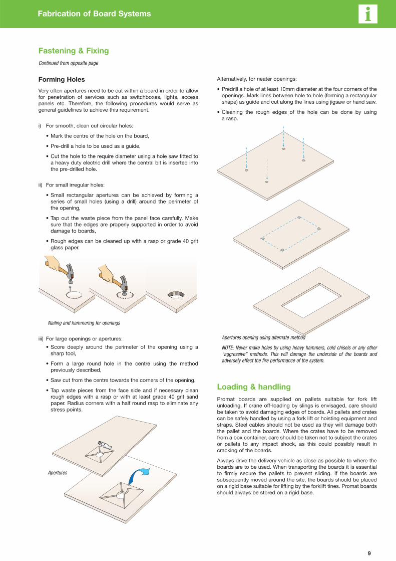
Forming Holes
Very often apertures need to be cut within a board in order to allow
for penetration of services such as switchboxes, lights, access
panels etc. Therefore, the following procedures would serve as
general guidelines to achieve this requirement.
i) For smooth, clean cut circular holes:
• Mark the centre of the hole on the board,
• Pre-drill a hole to be used as a guide,
• Cut the hole to the require diameter using a hole saw fitted to
a heavy duty electric drill where the central bit is inserted into
the pre-drilled hole.
ii) For small irregular holes:
• Small rectangular apertures can be achieved by forming a
series of small holes (using a drill) around the perimeter of
the opening,
• Tap out the waste piece from the panel face carefully. Make
sure that the edges are properly supported in order to avoid
damage to boards,
• Rough edges can be cleaned up with a rasp or grade 40 grit
glass paper.
Nailing and hammering for openings
iii) For large openings or apertures:
• Score deeply around the perimeter of the opening using a
sharp tool,
• Form a large round hole in the centre using the method
previously described,
• Saw cut from the centre towards the corners of the opening,
• Tap waste pieces from the face side and if necessary clean
rough edges with a rasp or with at least grade 40 grit sand
paper. Radius corners with a half round rasp to eliminate any
stress points.
Apertures
Alternatively, for neater openings:
• Predrill a hole of at least 10mm diameter at the four corners of the
openings. Mark lines between hole to hole (forming a rectangular
shape) as guide and cut along the lines using jigsaw or hand saw.
• Cleaning the rough edges of the hole can be done by using
a rasp.
Apertures opening using alternate method
NOTE: Never make holes by using heavy hammers, cold chisels or any other
“aggressive” methods. This will damage the underside of the boards and
adversely effect the fire performance of the system.
Loading & handling
Promat boards are supplied on pallets suitable for fork lift
unloading. If crane off-loading by slings is envisaged, care should
be taken to avoid damaging edges of boards. All pallets and crates
can be safely handled by using a fork lift or hoisting equipment and
straps. Steel cables should not be used as they will damage both
the pallet and the boards. Where the crates have to be removed
from a box container, care should be taken not to subject the crates
or pallets to any impact shock, as this could possibly result in
cracking of the boards.
Always drive the delivery vehicle as close as possible to where the
boards are to be used. When transporting the boards it is essential
to firmly secure the pallets to prevent sliding. If the boards are
subsequently moved around the site, the boards should be placed
on a rigid base suitable for lifting by the forklift tines. Promat boards
should always be stored on a rigid base.

10
Fabrication of Board Systems
Loading & handling
Storage
Promat boards are supplied with protective plastic sheet wrapped
around the timber crates. This protection should not be removed
until the boards are ready for use.
In general, the following steps should be taken to ensure that the
boards remain in good condition during storage.
a) Promat boards should be stored on a covered and dry, level
ground, away from the working area or mechanical plant.
Stacking of Promat boards
b) Pallets should be a maximum of 800mm high, on firm level
ground. If two or more pallets are stacked, the total stack height
must be less than 3200mm.
Maximum height of stacking
c) The boards must be protected from inclement weather.
Protection of Promat boards
d) The boards must be stored under cover.
Storage of Promat boards
Handling
The following recommendations must always be taken into account
when handling the panels.
i) Wherever possible, always lift boards from the stack below
rather than slide board on board. This will prevent damage or
scratches occuring to the lower boards.
Lifting of Promat boards
ii) Always carry the boards on edge but do not store on edge.
Ensure edges do not get damaged when handling sheets.
Carrying Promat boards
Cutting
PROMATECT® 100 boards can be worked with conventional
woodworking equipment although the use of hand saws with
hardened teeth is recommended (see pages 11 and 12 for details).
Boards greater than 8mm in thickness may be more easily cut using
a power circular saw in conjunction with tungsten carbide tipped
blades or a jigsaw. For rough cutting, 8mm sheets can be deeply
scribed and broken over a straight edge.
Promat recommend that all cutting should be carried out in well
ventilated spaces, using dust extraction. Operators should wear
protective face masks at all times.
There are a wide variety of applications and fixing methods possible
with Promat boards The method to be used is dependent on a
number of factors, amongst which include:
1) The shape of boards, be they square, rectangular, circular etc;
2) The location where the work is to be carried out, be it industrial,
commercial, on site or off site etc;
3) The quality of workmanship required.
Promat boards can be cut on site fairly easy. However, if a large
amount of boards are to be cut, it is recommended that cutting is
carried out off site under controlled conditions as much as possible
to ensure good quality of finished edges etc.
Continued on opposite page
11
Fabrication of Board Systems
Continued from opposite page
A few general rules should be observed when working with
Promat boards. These are as follows.
• For industrial use and extended cutting life of tools, working with
diamond tipped saws is recommended. Experience shows that
tools with carbide teeth will provide a more than adequate cut but
the tools will wear at a faster rate.
• High speed electric tools generate very fine dust. Inhaling fine
dust can be harmful to health. Therefore, dust extraction or wet
cutting is required. Although Promat boards contain no harmful
fibres, inhalation of excessive nuisance dust can be detrimental.
Promat recommends that when cutting or drilling any fibre cement
products, appropriate face masks should always be worn.
• Slow running tools produce coarse dust or chips but are not so
efficient at cutting.
• The speed of cutting is best determined by:
- thickness of the board;
- hardness of the board;
- condition of the blade.
• The boards must be held firm during cutting to avoid slippage and
vibration which can lead to chipping of the board edges.
• The choice of the most appropriate tool for use in each country
will depend on custom, practice and local regulations.
Industrial Machines
Industrial machines are used for continuous cutting over long
periods of time, for large quantities and for high efficiency. The
following types can be identified.
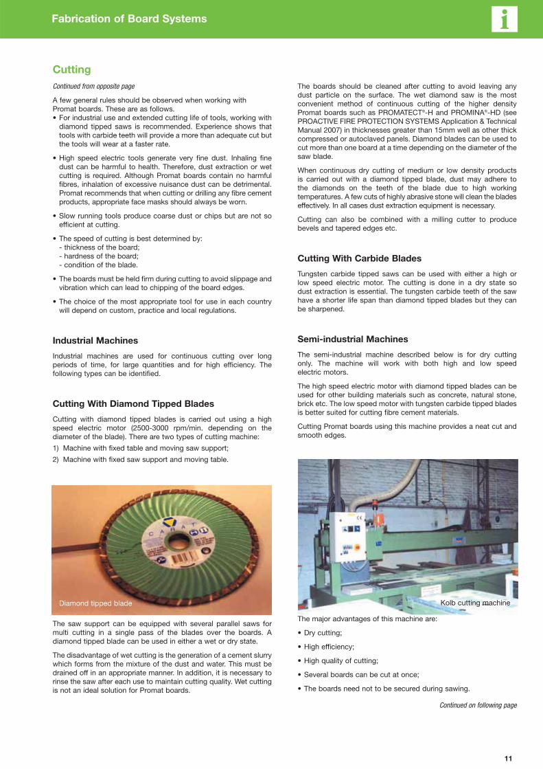
Cutting With Diamond Tipped Blades
Cutting with diamond tipped blades is carried out using a high
speed electric motor (2500-3000 rpm/min. depending on the
diameter of the blade). There are two types of cutting machine:
1) Machine with fixed table and moving saw support;
2) Machine with fixed saw support and moving table.
The saw support can be equipped with several parallel saws for
multi cutting in a single pass of the blades over the boards. A
diamond tipped blade can be used in either a wet or dry state.
The disadvantage of wet cutting is the generation of a cement slurry
which forms from the mixture of the dust and water. This must be
drained off in an appropriate manner. In addition, it is necessary to
rinse the saw after each use to maintain cutting quality. Wet cutting
is not an ideal solution for Promat boards.
The boards should be cleaned after cutting to avoid leaving any
dust particle on the surface. The wet diamond saw is the most
convenient method of continuous cutting of the higher density
Promat boards such as PROMATECT®-H and PROMINA®-HD (see
PROACTIVE FIRE PROTECTION SYSTEMS Application & Technical
Manual 2007) in thicknesses greater than 15mm well as other thick
compressed or autoclaved panels. Diamond blades can be used to
cut more than one board at a time depending on the diameter of the
saw blade.
When continuous dry cutting of medium or low density products
is carried out with a diamond tipped blade, dust may adhere to
the diamonds on the teeth of the blade due to high working
temperatures. A few cuts of highly abrasive stone will clean the blades
effectively. In all cases dust extraction equipment is necessary.
Cutting can also be combined with a milling cutter to produce
bevels and tapered edges etc.
Cutting With Carbide Blades
Tungsten carbide tipped saws can be used with either a high or
low speed electric motor. The cutting is done in a dry state so
dust extraction is essential. The tungsten carbide teeth of the saw
have a shorter life span than diamond tipped blades but they can
be sharpened.
Semi-industrial Machines
The semi-industrial machine described below is for dry cutting
only. The machine will work with both high and low speed
electric motors.
The high speed electric motor with diamond tipped blades can be
used for other building materials such as concrete, natural stone,
brick etc. The low speed motor with tungsten carbide tipped blades
is better suited for cutting fibre cement materials.
Cutting Promat boards using this machine provides a neat cut and
smooth edges.
The major advantages of this machine are:
• Dry cutting;
• High efficiency;
• High quality of cutting;
• Several boards can be cut at once;
• The boards need not to be secured during sawing.
Continued on following page
Diamond tipped blade Kolb cutting machine
Cutting
12
Fabrication of Board Systems
Continued from previous page
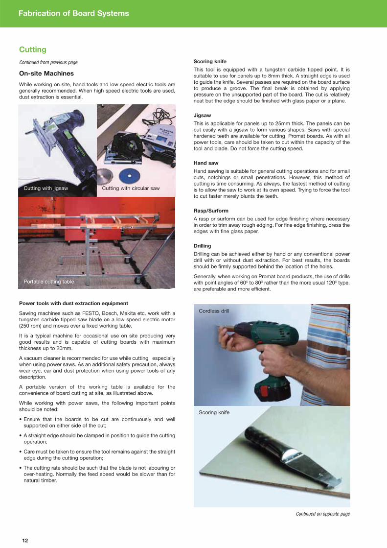
On-site Machines
While working on site, hand tools and low speed electric tools are
generally recommended. When high speed electric tools are used,
dust extraction is essential.
Power tools with dust extraction equipment
Sawing machines such as FESTO, Bosch, Makita etc. work with a
tungsten carbide tipped saw blade on a low speed electric motor
(250 rpm) and moves over a fixed working table.
It is a typical machine for occasional use on site producing very
good results and is capable of cutting boards with maximum
thickness up to 20mm.
A vacuum cleaner is recommended for use while cutting especially
when using power saws. As an additional safety precaution, always
wear eye, ear and dust protection when using power tools of any
description.
A portable version of the working table is available for the
convenience of board cutting at site, as illustrated above.
While working with power saws, the following important points
should be noted:
• Ensure that the boards to be cut are continuously and well
supported on either side of the cut;
• A straight edge should be clamped in position to guide the cutting
operation;
• Care must be taken to ensure the tool remains against the straight
edge during the cutting operation;
• The cutting rate should be such that the blade is not labouring or
over-heating. Normally the feed speed would be slower than for
natural timber.
Scoring knife
This tool is equipped with a tungsten carbide tipped point. It is
suitable to use for panels up to 8mm thick. A straight edge is used
to guide the knife. Several passes are required on the board surface
to produce a groove. The final break is obtained by applying
pressure on the unsupported part of the board. The cut is relatively
neat but the edge should be finished with glass paper or a plane.
Jigsaw
This is applicable for panels up to 25mm thick. The panels can be
cut easily with a jigsaw to form various shapes. Saws with special
hardened teeth are available for cutting Promat boards. As with all
power tools, care should be taken to cut within the capacity of the
tool and blade. Do not force the cutting speed.
Hand saw
Hand sawing is suitable for general cutting operations and for small
cuts, notchings or small penetrations. However, this method of
cutting is time consuming. As always, the fastest method of cutting
is to allow the saw to work at its own speed. Trying to force the tool
to cut faster merely blunts the teeth.
Rasp/Surform
A rasp or surform can be used for edge finishing where necessary
in order to trim away rough edging. For fine edge finishing, dress the
edges with fine glass paper.
Drilling
Drilling can be achieved either by hand or any conventional power
drill with or without dust extraction. For best results, the boards
should be firmly supported behind the location of the holes.
Generally, when working on Promat board products, the use of drills
with point angles of 60O to 80O rather than the more usual 120O type,
are preferable and more efficient.
Continued on opposite page
Cutting with jigsaw Cutting with circular saw
Portable cutting table
Scoring knife
Cutting
Cordless drill

13
Continued from opposite page
Flush Jointing Between Boards
PROMATECT® 100 boards can be simply butt jointed with sheets
having square, bevelled or chamfered edges. If required, a filler may
be used to finish joints before decoration.
Flush Jointing
Flush jointing is applicable to most partition and ceiling
constructions. However, in some instances it may be also
applicable to external wall constructions.
Generally installations of concealed framed ceiling and partition
systems require crack-free flush jointing. The method of
constructing flush joints depends very much on the skills and know-
how of the installer, as well as the stability of the supporting
construction. It is recommended that the thickness of panels used
for flush jointing should be of at least 8mm thick. Thinner boards are
allowed only when they are to be rendered with synthetic binders or
textures at a later stage. Following are some guidelines for joint
finishing in order to achieve the required appearance. For further
information, please consult Promat Technical Department.
To obtain a flush joint it is preferable that all panels have recessed
edges where they abut one other. The long edges of sheets have
pre-formed recesses, the short edges do not. It is not advisable to
have a recessed edge adjoining a square edge. It is preferable to
recess the edges of cut sheets where they have to be flush jonted.
If this is not practical, then the width of the flush jointing of square
edge sheets shall be twice the width of the flush jointing for
recessed joints.
When the boards are ready for joint treatments, follow the steps
below to obtain the required finish.
a) After the installation of the boards, wait until the moisture content
in the sheet is equivalent to that of the air. This would normally
take approximately 24 hours to achieve. Once this equilibrium
moisture content is achieved, moisture induced movement will be
lower, thus there will be less risk of joints cracking.
b) Always work with clean tools and containers.
c) The work should be carried out in environment where the
ambient air temperature is at least 5OC or above.
d) Prepare the joint filler as per instructions prescribed by the
manufacturer. Always use clean water.
e) Fill the bevel with sufficient joint filler (see illustration below).
f) Apply a layer of reinforcing paper tape over the filler and cover
the complete surface of the tape with excessive amount of joint
filler (well-embeded) using a trowel.
g) Remove any irregular surfaces on the joint by scraping away
using the back of the trowel.
h) Apply a second layer of joint filler with wide trowel.
i) Wait until it is completely cured.
j) Depending on the level of finishing required, an eventual last
layer of joint finisher can be applied with a 280mm wide
(preferably curved) trowel.
Joint fillers normally manufactured for use with plasterboards are
suitable for flush jointing of Promat board when installed within
dry areas.
It is recommended that areas to which filler is to be applied should
be pre-wet so that as boards gradually dry, tensile stresses and
sufficient adhesion are created in the joints.
Pre-wetting the boards ensures they do not rapidly absorb the
moisture from the filler, thus avoiding occurrence of cracks in
the joint.
Filling the joint Applying reinforcing tape Covering the tape Joint finishing
Cutting
Fabrication of Board Systems

14
Fabrication of Board Systems
Plastering
PROMATECT® 100 boards have high suction and while successful
skim coats are easily obtained, some care is capability needed to
retard the rapid drying of plaster coats, especially in areas of high
temperature. If plastering is essential, please consult the Promat
Technical Department.
It is recommended that a small test area is plastered initially to
ensure that the boards have been adequately sealed. It is advisable
that the use of self-adhesive or hessian scrim applied over joints and
internal angles is considered. Paper scrim is not recommended.
NOTE: The bonding agent and plaster manufacturer’s recom-
mendations must be followed at all times.
Tiling
PROMATECT® 100 boards can be tiled, provided due consideration
is given to the installation of the boards and the requirements for
additional framing prior to applying the tiles. It should be carefully
noted that Promat systems are used for their fire resistance
properties. Therefore placing additional weight on the system, such
as ceramic or marble tiling for instance, can have a significant effect
on the overall performance of the system.
It is for this reason that additional framing is required for partition
systems etc. which are to bear the weight of tiles and still maintain
their fire performance.
As a general rule of thumb, partition systems to be tiled should be
constructed with framing at nominal 450mm centres in both vertical
and horizontal orientations. Minimum board thickness can apply.
While tiling these boards can be successfully achieved, care needs
to be taken in sealing the boards thoroughly before applying any tile
adhesive, due to the very high suction the boards have and which
in turn accelerates the setting time of the tile adhesive. Please
consult the Promat Technical Department.
Painting
All coatings should be supplied by a reputable manufacturer and
their recommendations regarding surface preparation, sealing and
finish coating should be followed at all times.
PROMATECT® 100 boards have an attractive, smooth finish but if
required can be painted with emulsion or oil based paints. With
water based paints, a diluted first coat should be used. For oil
based paints use a universal primer. An alkali resisting primer is
not required.
Depending upon the type of finish used, it should be noted that in
certain circumstances, i.e. when viewed in a glancing light, some
minor surface imperfections may show.
Plastering a board joint Tiling on a board surface Painting a board surface

Chapter 2:
Structural Steel
ProtectionGeneral Information/Definition &
Calculation for Section Factor ___________________________ 16
Calculation of Hp/A Values ______________________________ 18
Hp/A Tables for Steel Work Encasement _________________ 19
Column Cladding _______________________________________ 30
Beam Cladding _________________________________________ 31
15

16
Structural Steel General Information /
Definition & Calculations For Section Factor
Introduction
Numerous research programmes show that some types of fully
stressed steel sections can achieve a fire resistance of 30 minutes
without any additional protection materials being applied. However,
these apply to a limited number of steel sections only, based on
the allowable Section Factor Hp/A. Section Factor is a common
term used in fire protection for steelwork and is discussed in
detail below.
Typical building regulations usually require certain elements of
structure to be fire resistant for up to 120 minutes or up to a
specified minimum period of time. The thickness of any fire
protection material depends on a number of factors, such as:
• Duration of fire resistance specified;
• Type of protection used (e.g. board, paint, spray etc);
• Perimeter of the part of steel section exposed to fire;
• Shape and dimensions of the steel section.
To determine how these various factors affect the fire resistance, all
Promat products and systems have been tested at nationally
accredited laboratories around the world to a variety of standards,
e.g. BS476: Part 21, AS1530: Part 4, DIN 4102 and ASTM E119.
Tests carried out in accordance with AS1530: 4 and BS476: Part 21
are performed on both loaded and unloaded beams and columns
which are clad with fire protection material. Steel surface
temperatures are monitored with thermocouples to assess the
performance of the cladding. Steel that is stressed in accordance
with the design guides BS449 or BS5950: Part 1 (Australian
equivalent AS4100), begin to lose their design margin of safety at
temperatures around 550°C. The table at above right shows how
the strength of steel reduces as temperatures rise.
Variation of effective yield strength factor of
normal structural steels with temperature
Temperature20 100 200 300 400 500 600 700 800
(°C)
Effective yield1.00 1.00 1.00 1.00 1.00 0.78 0.47 0.23 0.11
strength factor
Example: At 700°C, the effective yield strength of Grade 43 (S275) steel is
0.23 x 275 = 63.25N/mm2.
The above is extracted from the ASFP publication “Fire Protection for Structural
Steel in Buildings”, commonly known as “The Yellow Book”.
A range of unloaded sections are also tested to obtain data for
analytical calculation with the aid of a computer, to measure exactly
how much protection is needed for the most common steel
sections and for providing fire resistance for different time periods.
IMPORTANT NOTE: When using Promat protection systems for
structural steelwork, conservative limiting temperatures of 550°C
and 620°C are referred to for columns and beams respectively and
are in general use throughout this section. Apart from temperature
data, the fire tests also need to demonstrate the ability of cladding
to remain in place, usually described as “stickability” of the material,
for the maximum duration for which the protection may be required.
The availability of thin boards and the low weight of Promat
systems, plus the possibility of prefabrication, ensure maximum
cost-efficiency.
Section Factor (Hp/A)
The degree of fire protection provided depends on the Hp/A Section
Factor for the steel section. The Hp/A factor is a function of the area
of the steel exposed to the fire and the mass of the steel section.
The higher the Hp/A, the faster the steel section heats up and so the
greater the thickness of fire protection material required.
It should be noted that in recently published European design
standards, the section factor is presented as A/V which has the same
numerical value as Hp/A. A/V measures the rate of temperature
increase of a steel cross-section by the ratio of the heated surface
area to the volume. It is likely to gradually replace the use of Hp/A
(also sometimes referred to as ESA/M or Exposed Surface
Area/Mass) in the future.
Depending on type of material used for protection, the calculation
method for Hp/A value may differ. Generally there are two methods
of construction for the protection materials. These are box
protection and profile protection.
Box Protection
For box protection, Hp is the sum of the inside dimensions of
the smallest possible rectangular or square encasement of the
steel section (except for circular hollow sections) as shown on
pages 18 and 19.
Where a steel section abuts or is built into a fire resisting wall or
floor, the surface in contact with or the surface within the wall or
floor is ignored when calculating Hp.
However, the value A is always the total cross-sectional area of the
whole steel section.
Profile Protection
Encasements following the profile of the steel section will generally
have a higher Hp/A section factor than a box encasement. One
exception is circular hollow sections as detailed in the following
pages. If required, please contact a local Promat Technical
Department for further advice.
The serial size and mass per metre of most steel sections are
available in tables from steel manufacturers. Sometimes such tables
also provide Hp/A values calculated for 3 or 4-sided box protection.
Upon request, Promat Technical Department will provide assistance
in calculating Hp/A section factors and required material thicknesses.
As a general guide, please refer to pages 18 and 19. Below is an
example of calculation section for a beam box protection.
Example: Steel beam, serial size 406mm x 178mm x 54kg/m
to be encased on 3 sides
Serial size = 406mm x 178mm
Actual size = 406.2mm x 177.6mm
Hp = B + 2 D
= 177.6 + 402.6 + 402.6
= 982.8mm (0.9828m)
A = 68.1cm2 (0.00681m2)
Hp/A = 0.9828 ÷ 0.00681
= 144.3
= 145m-1
The value of A, the cross-sectional area, can be obtained either
from steelwork tables or by accurate measurement. However, if
the mass per metre is known, the Hp/A value can be calculated
as follows:
Hp=
7850 x Hp
A W
Where W = Mass of per metre (kg/m)
Where 7850 = Nominal density of steel
Where Hp = Heated Perimeter
NOTE: Calculation for profile protection can be simplified by
ignoring the thickness of the steel section. As such, the value
obtained is slightly conservative. For instance, a universal beam
protected on all 4 sides, the calculation of perimeter Hp is simplified
to 4B + 2D. The shape of the steel section can also play an
important role when determining the require thickness of a
protection material. On the following page is some reference
information. For details on steel profiles not outlined here, please
consult Promat Technical Department.

17
Structural Steel Definition & Calculations For Section Factor
Castellated Sections / Cellform BeamsThese heat up faster than the original section from which they were
produced. Protection thickness should therefore be 20% greater
than those calculated from the Hp/A value of the original section
from which the castellated section is formed.
However, it should be noted that the above information is now
considered somewhat out of date and a new, more scientific
approach is applied for the protection of castellated sections. The
following is taken from Fire Protection For Structural Steel In
Buildings, 4th Edition published by the ASFP (see www.asfp.org.uk).
The recommended method of obtaining the section factor (Hp/A) for
castellated sections is now amended as follows. The
recommendation from the Steel Construction Institute, as published
in RT1085, that for castellated sections and cellular beams
manufactured from all rolled steel sections and from welded plate,
the Section Factor for both passive and active fire protection
systems should be calculated as:
Section factor [m-1] = 1400/t
Where t = the thickness [mm] of the lower steel web
and applies for beams made from all
steel rolled sections and from welded
steel plate.
It should also be noted that there are a number of conditions
attached to the use of this calculation method, and these are
detailed in the ASFP “Yellow Book” publication mentioned above.
It should further be noted that the above rule does NOT apply
to intumescent paints, where the ability of a reactive coating
product to provide protection to the critical areas of the beam
is very product specific. Individual protection products,
normally quite similar in performance when compared on the
basis of rolled steel sections, may require radically different
thicknesses for the same cellular beam.
Structural Hollow SectionThe same thickness of Promat board materials can be used on
hollow sections as on ‘I’ sections of the same Hp/A value. This rule
does NOT apply to intumescent products.
BracingBracing is included in a structure to give resistance to wind forces
and provide overall stiffness. Masonry walls and steel cladding
contribute to structural rigidity but these are rarely taken into
account in design. Also, the probability of a major fire occurrence
concurrent with maximum wind load is remote (see BS5950: Part 8
or AS 4100). It seems unreasonable therefore to apply the 550°C
steel temperature criteria to bracing. While each case must be
judged on individual merits, protection to bracing is generally not
necessary, but where it is required the Hp/A value of the bracing
section or 200m-1 should be used, whichever is the lesser.
Lattice MembersAs the determination of the protection necessary to protect lattice
members requires broad consideration of the lattice design, please
consult a local Promat Technical Department for advice concerning
such steel sections.
Partially Exposed MembersWhere columns or beams are partly built into or are in close contact
with walls or floors, the protection afforded to the steelwork by the
wall or floor should be taken into account. In those instances where
the steel section sits within or against masonry or concrete
constructions, this will give protection to the adjacent surface of the
steelwork. Thus, for the purpose of determining the heated perimeter
(Hp), this should be taken as only that part of the steel section which
is exposed. It should be noted that where the steelwork penetrates
both sides of a fire resisting construction, i.e. a wall protruding into
a space which has an open end, simultaneous attack from fire on
both sides may occur on columns partially exposed within the wall.
In such a situation, the section factor should be calculated based
upon the sum of the areas exposed to fire on either side of the wall
and the total volume of the steel section. Note that separating
elements are generally required to offer a performance including the
insulation criteria of 140°C/180°C. Therefore, where a steel section
passes through a separating element and is exposed on both sides,
consideration must also be given to providing sufficient protection
not only to maintain the temperature of the steel section below
550°C but also to ensure the surface temperature on the unexposed
face does not exceed the 140°C/180°C insulation criteria of the
separating element. Due allowance for any expected building
movement should also be considered.
External Lightweight WallsWhere the structural elements form portal legs supporting a
lightweight external wall, the insulation performance required of the
wall may contribute to the protection of any column flange falling
within the thickness of the wall. In such cases, please consult the
local Promat Technical Department to confirm the board thickness
and which areas of such columns should be protected.
Internal Lightweight Walls/PartitionsWhere a column or beam is built into a fire resistant lightweight wall
or partition, the protection to the steelwork can generally be
designed on the assumption that only one side of the wall or
partition will be exposed to fire at any one time. The wall or partition
should be adequately secured to the column in such a way as to
ensure the wall or partition will not apply stress on the protection
encasement. Due allowance for any expected building movement
should be considered.
FloorsWhere beams are wholly within the cavity of a timber floor protected
by a PROMATECT® ceiling, test evidence shows that the cavity air
temperature of the floor is such that the beam will be adequately
protected to the same fire resistance by the ceiling that protects the
floor. Where the beam is wholly or partly below the line of the
PROMATECT® ceiling, the Hp should be based upon the portion of
the steel beam that is below ceiling level.
Beams Supporting Composite Floors
With Profiled Metal DeckingA series of fire resistance tests, jointly sponsored by ASFP
members (including Promat) and others, demonstrates that it is not
always necessary to fill the void formed between the top flange of
a beam and the underside of a profiled steel deck.
Recommendations based on the research have been published by
the Steel Construction Institute (UK) and for decks running
perpendicular to the beams, are as follows:
Dovetail decks
Voids may be left unfilled for all fire resistance periods; unless a fire
resisting wall or partition is located beneath the beam.
Trapezoidal decks
Generally, voids may be left unfilled for up to 60 minutes fire
resistance. Also, for 90 minutes if the board thickness used is
appropriate for the Hp/A + 15%. Care should be taken to ensure
that if the voids are unfilled, the main encasement will need to be
adequately secured. Please refer to Promat Technical Department
for advice.
For periods over 90 minutes the voids should be filled.
In all instances, voids should also be filled if a fire wall is located
beneath the beam, for all fire resistance periods. These
recommendations apply to board encasements. The trapezoidal
steel deck slab should be designed to act structurally with the
beam. If this is not the case, the voids should be filled for all fire
resistance periods.
How To Specify
1. Choose the material to be used.
PROMATECT® 100
A white board with a flat and smooth surface that provides high
insulation performance with minimum thickness, offering up to 150
minutes fire protection.
2. Determine the period of fire protection required.
3. Determine the section factor (Hp/A) of the steel section.
See opposite page.
4. Using the Hp/A factor and the required fire protection
period, determine the board thickness and fixing details.
Please refer to page 32.

18
Structural Steel Calculation of Hp/A Values
Hp/A Section Factor Profile
Protection configurations with values of perimeter Hp for use in the calculation of section factor Hp/A (A/V)
Steel section Profile protection
Universal beams,4 sides 3 sides
3 sides2 sides
1 side
universal columns (partially exposed) (partially exposed)
and joists (plain
and castellated)
Hp2B + 2D + 2(B - t) B + 2D + 2(B - t) B + 2d + (B - t) B + D + 2(B - t)/2
B= 4B + 2D - 2t = 3B + 2D - 2t = 2B + 2d-t = 2B + D -t
Structural and4 sides
3 sides 3 sides
rolled tees (flange to soffit) (toe of web to soffit)
Hp 2B + 2D B + 2DB + 2D + (B - t)
= 2B + 2D - t
Angles 4 sides3 sides 3 sides
(flange to soffit) (toe of flange to soffit)
Hp 2B + 2D B + 2DB + 2D + (B - t)
= 2B + 2D - t
Channels 4 sides3 sides 3 sides
(web to soffit) (flange to soffit)
Hp2B + 2D + 2(B - t) 2B + D + 2(B - t) B + 2D + 2(B - t)
= 4B + 2D - 2t = 4B + D - 2t = 3B + 2D - 2t
Hollow sections
(square or 4 sides 3 sides
rectangular)
Hp 2B + 2D B + 2D
Hollow sections
(circular)
Hp πD
NOTE: The values are approximate in that radii at corners and roots of all sections are ignored. In these figures Hp/A = A/V.

19
Hp/A Tables For Steelwork Encasement
Hp/A Section Factor Box
Protection configurations with values of perimeter Hp for use in the calculation of section factor Hp/A (A/V)
Steel section Profile protection
Universal beams,4 sides 3 sides
3 sides2 sides
1 side
universal columns (partially exposed) (partially exposed)
and joists (plain
and castellated)
Hp 2B + 2D B + 2D B + 2d B + D B
Structural and4 sides
3 sides 3 sides
rolled tees (flange to soffit) (toe of web to soffit)
Hp 2B + 2D B + 2D B + 2D
Angles 4 sides3 sides 3 sides
(flange to soffit) (toe of flange to soffit)
Hp 2B + 2D B + 2D B + 2D
Channels 4 sides3 sides 3 sides
(web to soffit) (flange to soffit)
Hp 2B + 2D 2B + D B + 2D
Hollow sections
(square or 4 sides 3 sides
rectangular)
Hp 2B + 2D B + 2D
Hollow sections
(circular)
NOTE: The air space created in boxing a section improves the insulation and value of Hp/A. Therefore, Hp higher than
profile protection would be anomalous. Hence, Hp is taken as the circumference of the tube and not 4D.
Hp πD
NOTE: The values are approximate in that radii at corners and roots of all sections are ignored. In these figures Hp/A = A/V.
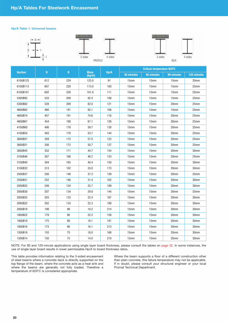
20
Hp/A Tables For Steelwork Encasement
Hp/A Table 1: Universal beams
Section D B Mass Hp/ACritical temperature 620OC
(kg/m) 30 minutes 60 minutes 90 minutes 120 minutes
610UB125 612 229 125.0 91 15mm 15mm 15mm 20mm
610UB113 607 228 113.0 100 15mm 15mm 15mm 25mm
610UB101 602 228 101.0 111 15mm 15mm 15mm 25mm
530UB92 533 209 92.4 108 15mm 15mm 15mm 25mm
530UB82 528 209 82.0 121 15mm 15mm 20mm 25mm
460UB82 460 191 82.1 106 15mm 15mm 15mm 25mm
460UB74 457 191 74.6 116 15mm 15mm 20mm 25mm
460UB67 454 190 67.1 128 15mm 15mm 20mm 25mm
410UB60 406 178 59.7 130 15mm 15mm 20mm 25mm
410UB54 403 178 53.7 144 15mm 15mm 20mm 25mm
360UB57 359 172 57.0 122 15mm 15mm 20mm 25mm
360UB51 356 172 50.7 137 15mm 15mm 20mm 25mm
360UB45 352 171 44.7 154 15mm 15mm 20mm 30mm
310UB46 307 166 46.2 133 15mm 15mm 20mm 25mm
310UB40 304 165 40.4 150 15mm 15mm 20mm 30mm
310UB32 313 102 33.0 173 15mm 15mm 20mm 30mm
250UB37 256 146 37.3 139 15mm 15mm 20mm 25mm
250UB31 252 146 31.4 162 15mm 15mm 20mm 30mm
250UB25 248 124 25.7 189 15mm 15mm 20mm 30mm
200UB30 207 134 29.8 144 15mm 15mm 20mm 25mm
200UB25 203 133 25.4 167 15mm 15mm 20mm 30mm
200UB22 202 133 22.3 189 15mm 15mm 20mm 30mm
200UB18 198 99 18.2 214 15mm 15mm 20mm 30mm
180UB22 179 90 22.2 158 15mm 15mm 20mm 30mm
180UB18 175 90 18.1 191 15mm 15mm 20mm 30mm
180UB16 173 90 16.1 213 15mm 15mm 20mm 30mm
150UB18 155 75 18.0 168 15mm 15mm 20mm 30mm
150UB14 150 75 14.0 210 15mm 15mm 20mm 30mm
NOTE: For 90 and 120-minute applications using single layer board thickness, please consult the tables on page 32. In some instances, the
use of single layer board results in lower permissable Hp/A to board thickness ratios.
This table provides information relating to the 3-sided encasement
of steel beams where a concrete deck is directly supported on the
top flange of the beam, where the concrete acts as a heat sink and
where the beams are generally not fully loaded. Therefore a
temperature of 620OC is considered appropriate.
Where the beam supports a floor of a different construction other
than plain concrete, this failure temperature may not be applicable.
If in doubt, please consult your structural engineer or your local
Promat Technical Department.

21
Hp/A Tables For Steelwork Encasement
DESIGNATION DEPTH OF WIDTH OF THICKNESS AREA OF PROFILE Hp/A BOX Hp/A
Serial size MassSECTION SECTION
Web FlangeSECTION
3 sides 3 sides 3 sides 4 sides 3 sides 3 sides 3 sides 4 sides
(mm) (kg/m) D (mm) B (mm) t (mm) T (mm) (cm2) (m-1) (m-1) (m-1) (m-1) (m-1) (m-1) (m-1) (m-1)
432 x 102 65.54 431.8 101.6 12.2 16.8 83.49 135 95 75 145 115 75 75 130
381 x 102 55.10 38.10 101.6 10.4 16.3 70.19 145 105 85 160 125 85 85 140
305 x 102 46.18 304.8 101.6 10.2 14.8 58.83 145 110 85 165 120 85 85 140
305 x 89 41.69 304.8 88.9 10.2 13.7 53.11 155 115 90 175 130 90 90 150
254 x 89 35.74 254.0 88.9 9.1 13.6 45.52 160 125 95 180 130 95 95 150
254 x 76 28.29 254.0 76.2 8.1 10.9 36.03 195 145 115 215 160 115 115 185
229 x 89 32.76 228.6 88.9 8.6 13.3 41.73 165 130 95 185 130 95 95 150
229 x 76 26.06 228.6 76.2 7.6 11.2 33.20 195 150 115 220 160 115 115 185
203 x 89 29.78 203.2 88.9 8.1 12.9 37.94 165 135 100 190 130 100 100 155
203 x 76 23.82 203.2 76.2 7.1 11.2 30.34 195 155 115 220 160 115 115 185
178 x 89 26.81 177.8 88.9 7.6 12.3 34.15 170 145 105 195 130 105 105 155
178 x 76 20.84 177.8 76.2 6.6 10.3 26.54 205 170 125 235 165 125 125 190
152 x 89 23.84 152.4 88.9 7.1 11.6 30.36 175 155 110 205 130 110 110 160
152 x 76 17.88 152.4 76.2 6.4 9.0 22.77 220 185 135 255 165 135 135 200
127 x 64 14.90 127.0 63.5 6.4 9.2 18.98 215 185 135 250 165 135 135 200
102 x 51 10.42 101.6 50.8 6.1 7.6 13.28 245 210 155 285 190 155 155 230
76 x 38 6.70 76.2 38.1 5.1 6.8 8.53 285 240 180 330 225 180 180 270
Hp/A Table 4: Channels
Hp/A Table 2: Universal columns
Section D B Mass Hp/ACritical temperature 550OC
(kg/m) 30 minutes 60 minutes 90 minutes 120 minutes
310UC158 372 311 158.0 68 15mm 15mm 15mm 15mm
310UC137 321 309 137.0 72 15mm 15mm 15mm 20mm
310UC118 315 307 118.0 83 15mm 15mm 15mm 20mm
310UC97 308 305 96.8 99 15mm 15mm 15mm 20mm
250UC89 260 256 89.0 91 15mm 15mm 15mm 20mm
250UC73 254 254 73.0 109 15mm 15mm 15mm 25mm
200UC60 210 205 60.0 109 15mm 15mm 15mm 25mm
200UC52 206 204 52.2 123 15mm 15mm 20mm 25mm
200UC46 203 203 46.2 138 15mm 15mm 20mm 25mm
152UC37 162 154 37.2 133 15mm 15mm 20mm 25mm
152UC30 158 153 30.0 162 15mm 15mm 20mm 30mm
152UC23 152 152 23.4 205 15mm 15mm 25mm 35mm
100UC15 97 99 14.8 208 15mm 15mm 25mm 35mm
NOTE: For 90 and 120-minute applications using single layer board thickness, please consult the tables on page 32. In some instances, the
use of single layer board results in lower permissable Hp/A to board thickness ratios.

22
Hp/A Tables For Steelwork Encasement
Hp/A Table 5: Equal angles
SIZE THICKNESS MASS AREA OF PROFILE Hp/A BOX Hp/A
D x D tSECTION
3 sides 3 sides 4 sides 3 sides 4 sides
(mm) (mm) (kg/m) (cm2) (m-1) (m-1) (m-1) (m-1) (m-1)
200 x 200 24 71.1 90.6 65 85 85 65 90
20 59.9 76.3 75 100 105 80 105
18 54.2 69.1 85 110 115 85 115
16 48.5 61.8 95 125 125 95 130
150 x 150 18 40.1 51.0 85 110 115 90 115
15 33.8 43.0 100 135 135 105 140
12 27.3 34.8 125 165 170 130 170
10 23.0 29.3 150 200 200 155 205
120 x 120 15 26.6 33.9 105 135 140 105 140
12 21.6 27.5 125 170 170 130 175
10 18.2 23.2 150 200 200 155 205
8 14.7 18.7 185 250 250 190 255
100 x 100 15 21.9 27.9 105 135 140 105 145
12 17.8 22.7 130 170 170 130 175
8 12.2 15.5 185 250 250 195 255
90 x 90 12 15.9 20.3 130 170 175 135 175
10 13.4 17.1 150 200 205 155 210
8 10.9 13.9 190 250 250 195 260
6 8.30 10.6 245 330 330 255 340
80 x 80 10 11.9 15.1 155 205 205 160 210
8 9.63 12.3 190 250 255 195 260
6 7.34 9.35 250 330 335 255 340
70 x 70 10 10.3 13.1 155 205 210 160 215
8 8.36 10.6 190 250 255 195 260
6 6.38 8.13 250 330 335 255 340
60 x 60 10 8.69 11.1 155 205 210 160 215
8 7.09 9.03 190 250 260 200 265
6 5.42 6.91 250 330 335 260 345
5 4.57 5.82 300 395 400 305 410
50 x 50 8 5.82 7.41 195 255 260 200 270
6 4.47 5.69 255 335 340 260 350
5 3.77 4.80 300 400 405 310 415
45 x 45 6 4.00 5.09 255 335 340 265 350
5 3.38 4.30 300 400 405 310 415
4 2.74 3.49 370 490 495 385 510
40 x 40 6 3.52 4.48 255 340 345 265 355
5 2.97 3.79 305 400 410 315 420
4 2.42 3.08 375 495 500 390 515
25 x 25 5 1.77 2.26 315 415 430 335 445
4 1.45 1.85 390 515 525 405 545
3 1.11 1.42 505 680 685 530 710
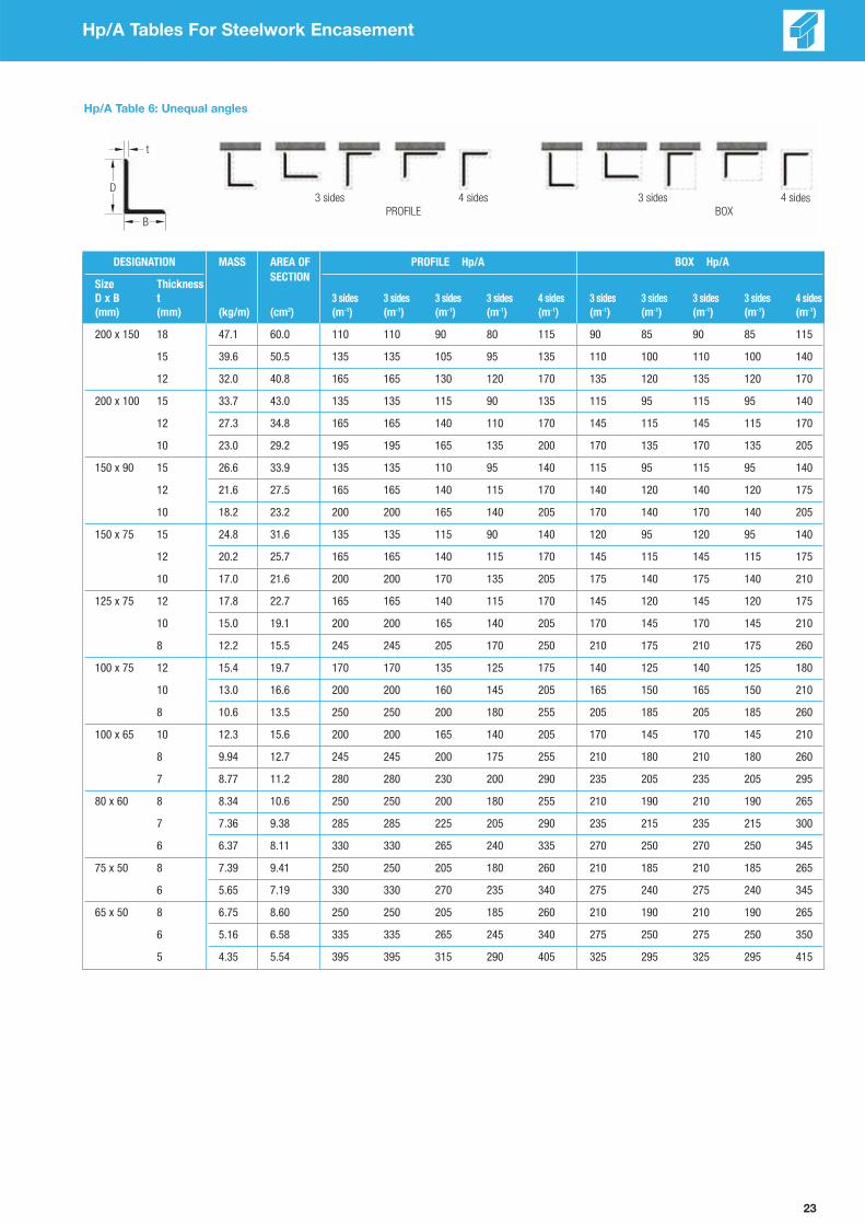
23
Hp/A Tables For Steelwork Encasement
Hp/A Table 6: Unequal angles
DESIGNATION MASS AREA OF PROFILE Hp/A BOX Hp/A
Size ThicknessSECTION
D x B t 3 sides 3 sides 3 sides 3 sides 4 sides 3 sides 3 sides 3 sides 3 sides 4 sides
(mm) (mm) (kg/m) (cm2) (m-1) (m-1) (m-1) (m-1) (m-1) (m-1) (m-1) (m-1) (m-1) (m-1)
200 x 150 18 47.1 60.0 110 110 90 80 115 90 85 90 85 115
15 39.6 50.5 135 135 105 95 135 110 100 110 100 140
12 32.0 40.8 165 165 130 120 170 135 120 135 120 170
200 x 100 15 33.7 43.0 135 135 115 90 135 115 95 115 95 140
12 27.3 34.8 165 165 140 110 170 145 115 145 115 170
10 23.0 29.2 195 195 165 135 200 170 135 170 135 205
150 x 90 15 26.6 33.9 135 135 110 95 140 115 95 115 95 140
12 21.6 27.5 165 165 140 115 170 140 120 140 120 175
10 18.2 23.2 200 200 165 140 205 170 140 170 140 205
150 x 75 15 24.8 31.6 135 135 115 90 140 120 95 120 95 140
12 20.2 25.7 165 165 140 115 170 145 115 145 115 175
10 17.0 21.6 200 200 170 135 205 175 140 175 140 210
125 x 75 12 17.8 22.7 165 165 140 115 170 145 120 145 120 175
10 15.0 19.1 200 200 165 140 205 170 145 170 145 210
8 12.2 15.5 245 245 205 170 250 210 175 210 175 260
100 x 75 12 15.4 19.7 170 170 135 125 175 140 125 140 125 180
10 13.0 16.6 200 200 160 145 205 165 150 165 150 210
8 10.6 13.5 250 250 200 180 255 205 185 205 185 260
100 x 65 10 12.3 15.6 200 200 165 140 205 170 145 170 145 210
8 9.94 12.7 245 245 200 175 255 210 180 210 180 260
7 8.77 11.2 280 280 230 200 290 235 205 235 205 295
80 x 60 8 8.34 10.6 250 250 200 180 255 210 190 210 190 265
7 7.36 9.38 285 285 225 205 290 235 215 235 215 300
6 6.37 8.11 330 330 265 240 335 270 250 270 250 345
75 x 50 8 7.39 9.41 250 250 205 180 260 210 185 210 185 265
6 5.65 7.19 330 330 270 235 340 275 240 275 240 345
65 x 50 8 6.75 8.60 250 250 205 185 260 210 190 210 190 265
6 5.16 6.58 335 335 265 245 340 275 250 275 250 350
5 4.35 5.54 395 395 315 290 405 325 295 325 295 415
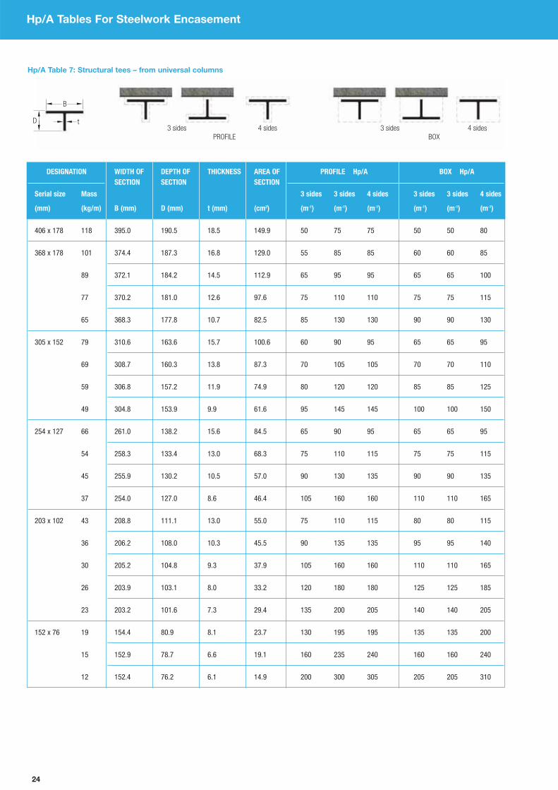
24
Hp/A Tables For Steelwork Encasement
Hp/A Table 7: Structural tees – from universal columns
DESIGNATION WIDTH OF DEPTH OF THICKNESS AREA OF PROFILE Hp/A BOX Hp/A
Serial size Mass
SECTION SECTION SECTION
3 sides 3 sides 4 sides 3 sides 3 sides 4 sides
(mm) (kg/m) B (mm) D (mm) t (mm) (cm2) (m-1) (m-1) (m-1) (m-1) (m-1) (m-1)
406 x 178 118 395.0 190.5 18.5 149.9 50 75 75 50 50 80
368 x 178 101 374.4 187.3 16.8 129.0 55 85 85 60 60 85
89 372.1 184.2 14.5 112.9 65 95 95 65 65 100
77 370.2 181.0 12.6 97.6 75 110 110 75 75 115
65 368.3 177.8 10.7 82.5 85 130 130 90 90 130
305 x 152 79 310.6 163.6 15.7 100.6 60 90 95 65 65 95
69 308.7 160.3 13.8 87.3 70 105 105 70 70 110
59 306.8 157.2 11.9 74.9 80 120 120 85 85 125
49 304.8 153.9 9.9 61.6 95 145 145 100 100 150
254 x 127 66 261.0 138.2 15.6 84.5 65 90 95 65 65 95
54 258.3 133.4 13.0 68.3 75 110 115 75 75 115
45 255.9 130.2 10.5 57.0 90 130 135 90 90 135
37 254.0 127.0 8.6 46.4 105 160 160 110 110 165
203 x 102 43 208.8 111.1 13.0 55.0 75 110 115 80 80 115
36 206.2 108.0 10.3 45.5 90 135 135 95 95 140
30 205.2 104.8 9.3 37.9 105 160 160 110 110 165
26 203.9 103.1 8.0 33.2 120 180 180 125 125 185
23 203.2 101.6 7.3 29.4 135 200 205 140 140 205
152 x 76 19 154.4 80.9 8.1 23.7 130 195 195 135 135 200
15 152.9 78.7 6.6 19.1 160 235 240 160 160 240
12 152.4 76.2 6.1 14.9 200 300 305 205 205 310
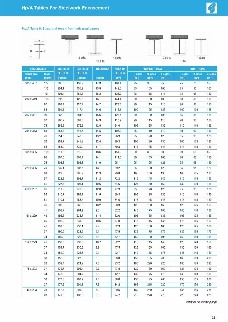
25
Hp/A Tables For Steelwork Encasement
Hp/A Table 8: Structural tees – from universal beams
DESIGNATION WIDTH OF DEPTH OF THICKNESS AREA OF PROFILE Hp/A BOX Hp/A
Serial size Mass SECTION SECTION SECTION 3 sides 3 sides 4 sides 3 sides 3 sides 4 sides
(mm) (kg/m) B (mm) D (mm) t (mm) (cm2) (m-1) (m-1) (m-1) (m-1) (m-1) (m-1)
305 x 457 127 305.5 459.2 17.3 161.4 75 95 95 75 75 95
112 304.1 455.2 15.9 142.6 85 105 105 85 85 105
101 303.4 451.5 15.2 128.2 95 115 115 95 95 120
292 x 419 113 293.8 425.5 16.1 144.4 80 100 100 80 80 100
97 292.4 420.4 14.7 123.6 90 115 115 90 90 115
88 291.6 417.4 14.0 112.1 100 125 125 100 100 125
267 x 381 99 268.0 384.8 15.6 125.4 80 100 105 85 85 105
87 266.7 381.0 14.3 110.2 90 115 115 90 90 120
74 265.3 376.9 12.9 94.0 105 135 135 110 110 135
254 x 343 85 255.8 346.5 14.5 108.3 85 110 110 90 90 110
76 254.5 343.8 13.2 96.9 95 120 120 95 95 125
70 253.7 341.8 12.4 89.3 105 130 130 105 105 135
63 253.0 339.0 11.7 79.8 115 145 145 115 115 150
305 x 305 119 311.5 316.5 18.6 151.9 60 80 80 60 60 85
90 307.0 308.7 14.1 114.0 80 105 105 80 80 110
75 304.8 304.8 11.9 95.1 95 125 125 95 95 130
229 x 305 70 230.1 308.5 13.1 89.2 95 120 120 95 95 120
63 229.0 305.9 11.9 79.8 105 130 135 105 105 135
57 228.2 303.7 11.2 72.2 115 145 145 115 115 145
51 227.6 301.1 10.6 64.6 125 160 160 130 130 165
210 x 267 61 211.9 272.3 12.8 77.9 95 120 125 95 95 125
55 210.7 269.7 11.6 69.3 105 135 135 110 110 140
51 210.1 268.4 10.9 64.6 115 145 145 115 115 150
46 209.3 266.6 10.2 58.9 125 160 160 125 125 160
41 208.7 264.2 9.6 52.2 140 175 180 140 140 180
191 x 229 49 192.8 233.7 11.4 62.6 105 135 135 105 105 135
45 192.0 231.8 10.6 57.0 115 145 145 115 115 150
41 191.3 230.1 9.9 52.3 125 160 160 125 125 160
37 190.5 228.6 9.1 47.5 135 175 175 135 135 175
34 189.9 226.8 8.5 42.7 150 190 195 150 150 195
152 x 229 41 153.5 232.5 10.7 52.2 115 145 145 120 120 150
37 152.7 230.6 9.9 47.5 125 155 160 130 130 160
34 151.9 228.6 9.1 42.7 140 175 175 145 145 180
30 152.9 227.3 8.0 38.0 150 195 200 160 160 200
26 152.4 224.9 7.6 33.2 180 220 225 180 180 225
178 x 203 37 179.7 206.4 9.7 47.5 120 160 160 125 125 160
34 178.8 204.7 8.8 42.7 135 175 175 140 140 180
30 177.8 203.2 7.8 38.0 150 195 200 155 155 200
27 177.6 201.3 7.6 34.2 165 215 220 170 170 220
140 x 203 23 142.4 201.2 6.9 29.5 180 230 230 185 185 235
20 141.8 198.6 6.3 24.7 215 270 275 220 220 275
Continued on following page

26
Hp/A Tables For Steelwork Encasement
Hp/A Table 8: Structural tees – from universal beams Continued from previous page
DESIGNATION WIDTH OF DEPTH OF THICKNESS AREA OF PROFILE Hp/A BOX Hp/A
Serial size Mass SECTION SECTION SECTION 3 sides 3 sides 4 sides 3 sides 3 sides 4 sides
(mm) (kg/m) B (mm) D (mm) t (mm) (cm2) (m-1) (m-1) (m-1) (m-1) (m-1) (m-1)
171 x 178 34 173.2 182.0 9.1 42.7 125 160 165 125 125 165
29 172.1 179.3 8.0 36.1 145 190 190 145 145 195
26 171.5 177.8 7.3 32.3 160 210 215 165 165 215
23 171.0 176.0 6.9 28.5 180 240 240 185 185 245
127 x 178 20 126.0 176.4 6.5 24.7 190 240 240 195 195 245
17 125.4 174.2 5.9 20.9 225 280 285 225 225 285
165 x 152 27 166.8 155.4 7.7 34.2 140 185 185 140 140 190
23 165.7 153.5 6.7 29.5 160 210 215 160 160 215
20 165.1 151.9 6.1 25.8 180 240 245 180 180 245
127 x 152 24 125.2 155.2 8.9 30.4 140 180 180 145 145 185
21 124.3 153.3 8.0 26.6 160 200 205 160 160 210
19 123.5 151.9 7.2 23.7 175 225 230 180 180 230
102 x 152 17 102.4 156.3 6.6 20.9 195 240 245 200 200 245
14 101.9 154.4 6.1 18.2 220 275 280 225 225 280
13 101.6 152.4 5.8 15.7 255 320 320 260 260 325
146 x 127 22 147.3 129.8 7.3 27.6 145 195 200 150 150 200
19 146.4 128.0 6.4 23.7 165 225 230 170 170 230
16 146.1 125.7 6.1 20.0 195 265 270 200 200 270
102 x 127 14 102.1 130.2 6.4 18.1 195 250 250 200 200 255
13 101.9 128.5 6.1 16.1 220 280 280 220 220 285
11 101.6 127.0 5.8 14.2 245 315 320 250 250 325
133 x 102 15 133.8 103.4 6.3 19.0 175 245 245 180 180 250
13 133.4 101.6 5.8 16.1 205 285 290 210 210 290
Hp/A Table 9: Rolled tees
SIZE MASS WIDTH OF DEPTH OF THICKNESS AREA OF PROFILE Hp/A BOX Hp/A
B x D SECTION SECTION SECTION 3 sides 3 sides 4 sides 3 sides 4 sides
(mm) (kg/m) D (mm) B (mm) t (mm) (cm2) (m-1) (m-1) (m-1) (m-1) (m-1)
51 x 51 6.92 50.8 50.8 9.5 8.82 175 220 230 175 230
4.76 50.8 50.8 6.4 6.06 250 325 335 250 335
44 x 44 4.11 44.4 44.4 6.4 5.24 255 325 340 255 340
3.14 44.4 44.4 4.8 4.00 335 430 445 335 445
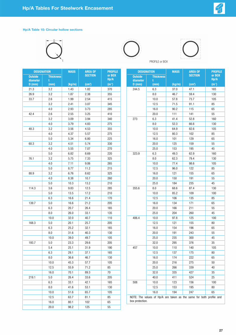
27
Hp/A Tables For Steelwork Encasement
Hp/A Table 10: Circular hollow sections
DESIGNATION MASS AREA OF PROFILE
Outside Thickness SECTION or BOX
diameter t Hp/A
D (mm) (mm) (kg/m) (cm2) (m-1)
21.3 3.2 1.43 1.82 370
26.9 3.2 1.87 2.38 355
33.7 2.6 1.99 2.54 415
3.2 2.41 3.07 345
4.0 2.93 3.73 285
42.4 2.6 2.55 3.25 410
3.2 3.09 3.94 340
4.0 3.79 4.83 275
48.3 3.2 3.56 4.53 355
4.0 4.37 5.57 275
5.0 5.34 6.80 225
60.3 3.2 4.51 5.74 330
4.0 5.55 7.07 270
5.0 6.82 8.69 220
76.1 3.2 5.75 7.33 325
4.0 7.11 9.06 265
5.0 8.77 11.2 215
88.9 3.2 6.76 8.62 325
4.0 8.38 10.7 260
5.0 10.3 13.2 210
114.3 3.6 9.83 12.5 285
5.0 13.5 17.2 210
6.3 16.6 21.4 170
139.7 5.0 16.6 21.2 205
6.3 20.7 26.4 165
8.0 26.0 33.1 135
10.0 32.0 40.7 110
168.3 5.0 20.1 25.7 205
6.3 25.2 32.1 165
8.0 31.6 40.3 130
10.0 39.0 49.7 105
193.7 5.0 23.3 29.6 205
5.4 25.1 31.9 190
6.3 29.1 37.1 165
8.0 36.6 46.7 130
10.0 45.3 57.7 105
12.5 55.9 71.2 85
16.0 70.1 89.3 70
219.1 5.0 26.4 33.6 205
6.3 33.1 42.1 165
8.0 41.6 53.1 130
10.0 51.6 65.7 105
12.5 63.7 81.1 85
16.0 80.1 102 65
20.0 98.2 125 55
DESIGNATION MASS AREA OF PROFILE
Outside Thickness SECTION or BOX
diameter t Hp/A
D (mm) (mm) (kg/m) (cm2) (m-1)
244.5 6.3 37.0 47.1 165
8.0 46.7 59.4 130
10.0 57.8 73.7 105
12.5 71.5 91.1 85
16.0 90.2 115 65
20.0 111 141 55
273 6.3 41.4 52.8 160
8.0 52.3 66.6 130
10.0 64.9 82.6 105
12.5 80.3 102 85
16.0 101 129 65
20.0 125 159 55
25.0 153 195 45
323.9 6.3 49.3 62.9 160
8.0 62.3 79.4 130
10.0 77.4 98.6 105
12.5 96.0 122 85
16.0 121 155 65
20.0 150 191 55
25.0 184 235 45
355.6 8.0 68.6 87.4 130
10.0 85.2 109 100
12.5 106 135 85
16.0 134 171 65
20.0 166 211 55
25.0 204 260 45
406.4 10.0 97.8 125 100
12.5 121 155 80
16.0 154 196 65
20.0 191 243 55
25.0 235 300 45
32.0 295 376 35
457 10.0 110 140 105
12.5 137 175 80
16.0 174 222 65
20.0 216 275 50
25.0 266 339 40
32.0 335 427 35
40.0 411 524 25
508 10.0 123 156 100
12.5 153 195 80
16.0 194 247 65
NOTE: The values of Hp/A are taken as the same for both profile and
box protection.

28
Hp/A Tables For Steelwork Encasement
Hp/A Table 11: Square hollow sections
DESIGNATION MASS AREA OF PROFILE Hp/A
Size Thickness SECTION
D x D t 3 sides 4 sides
(mm) (mm) (kg/m) (cm2) (m-1) (m-1)
20 x 20 2.0 1.12 1.42 425 565
2.5 1.35 1.72 350 465
25 x 25 2.0 1.43 1.82 410 550
2.5 1.74 2.22 340 450
3.0 2.04 2.60 290 385
3.2 2.15 2.74 275 365
30 x 30 2.5 2.14 2.72 330 440
3.0 2.51 3.20 280 375
3.2 2.56 3.38 265 355
40 x40 2.5 2.92 3.72 325 430
3.0 3.45 4.40 275 365
3.2 3.66 4.66 260 345
4.0 4.46 5.68 210 280
5.0 5.40 6.88 175 235
50 x 50 2.5 3.71 4.72 320 425
3.0 4.39 5.60 270 355
3.2 4.66 5.94 255 335
4.0 5.72 7.28 205 275
5.0 6.97 8.88 170 225
6.3 8.49 10.8 140 185
60 x 60 3.0 5.34 6.80 265 355
3.2 5.67 7.22 250 330
4.0 6.97 8.88 205 270
5.0 8.54 10.9 165 220
6.3 10.5 13.3 135 180
8.0 12.8 16.3 110 145
70 x 70 3.0 6.28 8.00 260 350
3.6 7.46 9.50 220 295
5.0 10.1 12.9 165 215
6.3 12.5 15.9 130 175
8.0 15.3 19.5 110 145
80 x 80 3.0 7.22 9.20 260 350
3.6 8.59 10.9 220 295
5.0 11.7 14.9 160 215
6.3 14.4 18.4 130 175
8.0 17.8 22.7 105 140
90 x 90 3.6 9.72 12.4 220 290
5.0 13.3 16.9 160 215
6.3 16.4 20.9 130 170
8.0 20.4 25.9 105 140
100 x 100 4.0 12.0 15.3 195 260
5.0 14.8 18.9 160 210
6.3 18.4 23.4 130 170
8.0 22.9 29.1 105 135
10.0 27.9 35.5 85 115
DESIGNATION MASS AREA OF PROFILE Hp/A
Size Thickness SECTION
D x D t 3 sides 4 sides
(mm) (mm) (kg/m) (cm2) (m-1) (m-1)
120 x 120 5.0 18.0 22.9 155 210
6.3 22.3 28.5 125 170
8.0 27.9 35.5 100 135
10.0 34.2 43.5 85 110
12.5 41.6 53.0 70 90
140 x 140 5.0 21.1 26.9 155 210
6.3 26.3 33.5 125 165
8.0 32.9 41.9 100 135
10.0 40.4 51.5 80 110
12.5 49.5 63.0 65 90
150 x 150 5.0 22.7 28.9 155 210
6.3 28.3 36.0 125 165
8.0 35.4 45.1 100 135
10.0 43.6 55.5 80 110
12.5 53.4 68.0 65 90
16.0 66.4 84.5 55 70
180 x 180 6.3 34.2 43.6 125 165
8.0 43.0 54.7 100 130
10.0 53.0 67.5 80 105
12.5 65.2 83.0 65 85
16.0 81.4 104 50 70
200 x 200 6.3 38.2 48.6 125 165
8.0 48.0 61.1 100 130
10.0 59.3 75.5 80 105
12.5 73.0 93.0 65 85
16.0 91.5 117 50 70
250 x 250 6.3 48.1 61.2 125 165
80 60.5 77.1 95 130
10.0 75.0 95.5 80 105
12.5 92.6 118 65 85
16.0 117 149 50 65
300 x 300 10.0 90.7 116 80 105
12.5 112 143 65 85
16.0 142 181 50 65
350 x 350 10.0 106 135 75 105
12.5 132 168 60 85
16.0 167 213 50 65
400 x 400 10.0 122 156 75 105
12.5 152 193 60 85
16.0 192 245 50 65
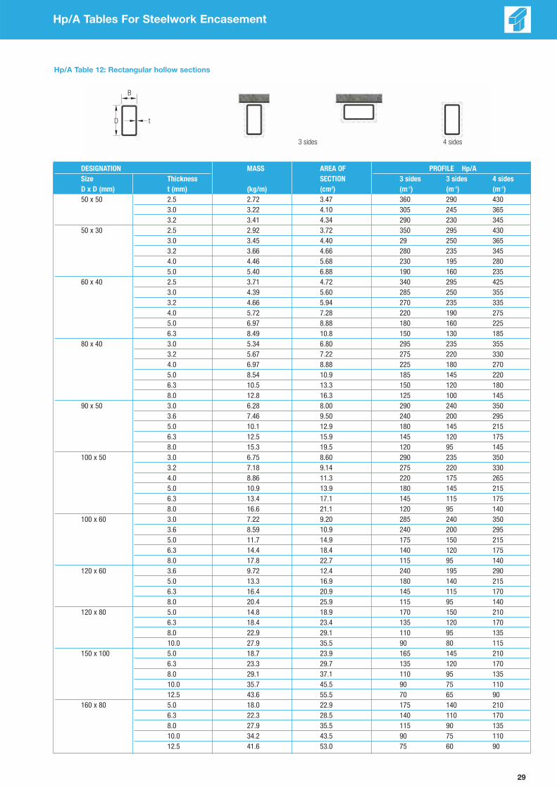
29
Hp/A Tables For Steelwork Encasement
Hp/A Table 12: Rectangular hollow sections
DESIGNATION MASS AREA OF PROFILE Hp/A
Size Thickness SECTION 3 sides 3 sides 4 sides
D x D (mm) t (mm) (kg/m) (cm2) (m-1) (m-1) (m-1)
50 x 50 2.5 2.72 3.47 360 290 430
3.0 3.22 4.10 305 245 365
3.2 3.41 4.34 290 230 345
50 x 30 2.5 2.92 3.72 350 295 430
3.0 3.45 4.40 29 250 365
3.2 3.66 4.66 280 235 345
4.0 4.46 5.68 230 195 280
5.0 5.40 6.88 190 160 235
60 x 40 2.5 3.71 4.72 340 295 425
3.0 4.39 5.60 285 250 355
3.2 4.66 5.94 270 235 335
4.0 5.72 7.28 220 190 275
5.0 6.97 8.88 180 160 225
6.3 8.49 10.8 150 130 185
80 x 40 3.0 5.34 6.80 295 235 355
3.2 5.67 7.22 275 220 330
4.0 6.97 8.88 225 180 270
5.0 8.54 10.9 185 145 220
6.3 10.5 13.3 150 120 180
8.0 12.8 16.3 125 100 145
90 x 50 3.0 6.28 8.00 290 240 350
3.6 7.46 9.50 240 200 295
5.0 10.1 12.9 180 145 215
6.3 12.5 15.9 145 120 175
8.0 15.3 19.5 120 95 145
100 x 50 3.0 6.75 8.60 290 235 350
3.2 7.18 9.14 275 220 330
4.0 8.86 11.3 220 175 265
5.0 10.9 13.9 180 145 215
6.3 13.4 17.1 145 115 175
8.0 16.6 21.1 120 95 140
100 x 60 3.0 7.22 9.20 285 240 350
3.6 8.59 10.9 240 200 295
5.0 11.7 14.9 175 150 215
6.3 14.4 18.4 140 120 175
8.0 17.8 22.7 115 95 140
120 x 60 3.6 9.72 12.4 240 195 290
5.0 13.3 16.9 180 140 215
6.3 16.4 20.9 145 115 170
8.0 20.4 25.9 115 95 140
120 x 80 5.0 14.8 18.9 170 150 210
6.3 18.4 23.4 135 120 170
8.0 22.9 29.1 110 95 135
10.0 27.9 35.5 90 80 115
150 x 100 5.0 18.7 23.9 165 145 210
6.3 23.3 29.7 135 120 170
8.0 29.1 37.1 110 95 135
10.0 35.7 45.5 90 75 110
12.5 43.6 55.5 70 65 90
160 x 80 5.0 18.0 22.9 175 140 210
6.3 22.3 28.5 140 110 170
8.0 27.9 35.5 115 90 135
10.0 34.2 43.5 90 75 110
12.5 41.6 53.0 75 60 90
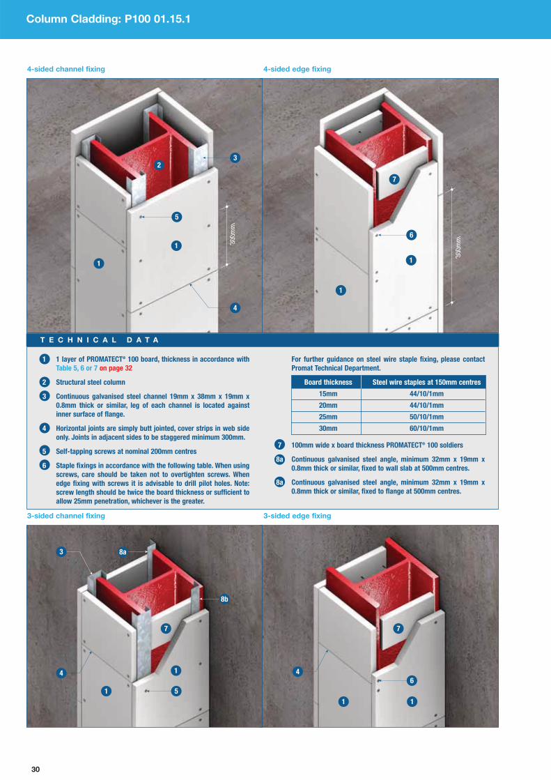
30
Column Cladding: P100 01.15.1
30
0m
m30
0m
m
4-sided channel fixing 4-sided edge fixing
3-sided channel fixing 3-sided edge fixing
1 1 layer of PROMATECT® 100 board, thickness in accordance with
Table 5, 6 or 7 on page 32
2 Structural steel column
3 Continuous galvanised steel channel 19mm x 38mm x 19mm x
0.8mm thick or similar, leg of each channel is located against
inner surface of flange.
4 Horizontal joints are simply butt jointed, cover strips in web side
only. Joints in adjacent sides to be staggered minimum 300mm.
5 Self-tapping screws at nominal 200mm centres
6 Staple fixings in accordance with the following table. When using
screws, care should be taken not to overtighten screws. When
edge fixing with screws it is advisable to drill pilot holes. Note:
screw length should be twice the board thickness or sufficient to
allow 25mm penetration, whichever is the greater.
For further guidance on steel wire staple fixing, please contact
Promat Technical Department.
Board thickness Steel wire staples at 150mm centres
15mm 44/10/1mm
20mm 44/10/1mm
25mm 50/10/1mm
30mm 60/10/1mm
7 100mm wide x board thickness PROMATECT® 100 soldiers
8a Continuous galvanised steel angle, minimum 32mm x 19mm x
0.8mm thick or similar, fixed to wall slab at 500mm centres.
8a Continuous galvanised steel angle, minimum 32mm x 19mm x
0.8mm thick or similar, fixed to flange at 500mm centres.
T E C H N I C A L D A T A

31
Beam Cladding: P100 02.15.1
1 1 layer of PROMATECT® 100 board, thickness in accordance withTable 5, 6 or 7 on page 32
2 Structural steel beam
3 PROMATECT® 100 soldiers, 100mm wide tightly wedged into the webof the steel at the butt joints. Joints in adjacent sides to be staggeredby a minimum of 300mm. For single layer protection the soldiershould be the same thickness as the layer used. For double layerprotection the soldier thickness should be the same as the thickerlayer. It should be noted that for deep beams which are being cladwith thicker boards for longer duration fire resistance, it may beadvisable to use soldiers installed at nominal 600mm centres, inorder to reduce the load on the soldiers and provide a more secureinstallation. For beams in excess of 400mm deep, a T-section soldiershould be used to provide a stiffer and stronger support.
4 PROMATECT® 100 cover strips, 100mm wide x board thickness(minimum 20mm), laid over joints. Screw fix casing to cover strips at100mm centres or staple fix at 50mm centres.
5a Secure side boards to soffit board using staple fixings in accordance
with the table below or use screws. Note: screw length should be
twice the board thickness or sufficient to allow 25mm penetration,
whichever is the greater.
Board thickness Steel wire staples at 150mm centres
15mm 44/10/1mm
20mm 44/10/1mm
25mm 50/10/1mm
30mm 60/10/1mm
5b Secure boards to channels and angles using self-drilling, self-tappingscrews at nominal 200mm centres.
5c Secure side board to soldiers using staples at 50mm centres orscrews at 100mm centres
6 Continuous galvanised steel channel, 19mm x 38mm x 19mm x0.8mm thick or similar, resting on lower flange, mechanical fixing toflange not required.
7a Continuous galvanised steel angle, minimum 32mm x 19mm x 0.8mmthick or similar, fixed to floor slab at nominal 500mm centres usingproprietary anchor fixing.
7b Continuous galvanised steel angle, minimum 32mm x 19mm x 0.8mmthick or similar, fixed to flange at nominal 500mm centres.
8 Staggered joints in adjacent boards by at least 300mm
9 Seal any irregularity between edge of board and substrate usingPROMASEAL® AN Acrylic Sealant, which should be applied to the fulldepth of the board thickness, e.g. for 20mm board, the sealant shouldbe 20mm deep.
T E C H N I C A L D A T A
3-sided edge fixing
3-sided channel fixing (option a)
3-sided channel fixing (option b)

32
Column / Beam Cladding: P100 01.15.1 / P100 02.15.1
Hp/A Ratio Table 5: PROMATECT® 100 column cladding for up to 150 minutes in accordance with
the requirements of AS1530: Part 4 (for critical temperature of 550°C)
Limiting section factor for Fire Resistance LevelBoard thickness*
30 minutes 60 minutes 90 minutes 120 minutes 150 minutes
15mm 260m-1 260m-1 114m-1 68m-1 –
20mm 260m-1 260m-1 185m-1 102m-1 70m-1
25mm 260m-1 260m-1 260m-1 145m-1 96m-1
30mm260m-1 260m-1 260m-1 201m-1 126m-1
(2 layers x 15mm)
35mm
(1 layer x 20mm + 260m-1 260m-1 260m-1 260m-1 163m-1
1 layer x 15mm)
40mm260m-1 260m-1 260m-1 260m-1 190m-1
(2 layers x 20mm)
*All single layer unless stated otherwise.
Hp/A Ratio Table 7: PROMATECT® 100 beam cladding for up to 150 minutes in accordance with
the requirements of AS1530: Part 4 (for critical temperature of 620°C)
Limiting section factor for Fire Resistance LevelBoard thickness*
30 minutes 60 minutes 90 minutes 120 minutes 150 minutes
15mm 260m-1 260m-1 115m-1 – –
20mm 260m-1 260m-1 232m-1 94m-1 –
25mm 260m-1 260m-1 260m-1 149m-1 85m-1
30mm260m-1 260m-1 260m-1 243m-1 120m-1
(2 layers x 15mm)
35mm
(1 layer x 20mm + 260m-1 260m-1 260m-1 260m-1 171m-1
1 layer x 15mm)
40mm260m-1 260m-1 260m-1 260m-1 213m-1
(2 layers x 20mm)
*All single layer unless stated otherwise.
Hp/A Ratio Table 6: PROMATECT® 100 beam cladding for up to 150 minutes in accordance with
the requirements of AS1530: Part 4 (for critical temperature of 550°C)
Limiting section factor for Fire Resistance LevelBoard thickness*
30 minutes 60 minutes 90 minutes 120 minutes 150 minutes
15mm 260m-1 260m-1 102m-1 – –
20mm 260m-1 260m-1 162m-1 92m-1 –
25mm 260m-1 260m-1 249m-1 129m-1 87m-1
30mm260m-1 260m-1 260m-1 176m-1 114m-1
(2 layers x 15mm)
35mm
(1 layer x 20mm + 260m-1 260m-1 260m-1 238m-1 146m-1
1 layer x 15mm)
40mm260m-1 260m-1 260m-1 260m-1 168m-1
(2 layers x 20mm)
*All single layer unless stated otherwise.
NOTES:
• All above tables provide information for applications providing 30 to 150 minutes fire resistance performance using single layer
PROMATECT® 100 up to 25mm thick. For greater thicknesses, double layer system is recommended.
• For use of single layer PROMATECT® 100 in 30mm or greater thickness, please consult the local Promat Technical Department.
This temperature of 620°C as per Table 7 applies only to the protection of beams where the structural element forms part of a composite floors
system, such that the beam and the floor move in concert and not as separate elements. The floor system must be of concrete construction.
This table does not apply to beams which are to be protected on four sides, or beams which are not permanently fixed to the concrete slab
above. Beams which are free to move independently or the concrete floor slab above, or where the floor is not formed of concrete should be
protected to 550°C using Table 6 above.

33
Column / Beam Cladding: P100 01.15.1 / P100 02.15.1
Architectural Specification
Only general information can be provided in this document. It is
recommended that the local Promat Technical Department be contacted to
confirm details not covered here.
Fixing methods are suitable for steel sections up to 686mm deep and 325mm
wide. For larger sections and when protecting multiple sections within a
single encasement, please consult the local Promat Technical Department.
Where a column cladding box encasement abuts a beam protected with a
profiled fire protection system, e.g. sprayed material, the column webs
should be sealed at the junction using PROMATECT® 100.
While the PROMATECT® 100 system is not recommended for the fire
protection of external steelwork, providing it is fixed in dry conditions, the
casing can withstand exposure to light rain or site water spillages for a few
weeks, after which it should be protected from exposure to water. If the
cladding is likely to be severely soaked after installation, protection from
weather should be employed.
(Screw fixing) (Staple fixing)
Area of Application
Exposed faces of steelwork internal to building, for up to 150 minutes fire protection in accordance with the requirements of BS476: Part 21: 1987 or
AS1530: Part 4.(1)
Location
__________________________________________________________________________________________________________________________________________(2)
Type of Fixing Type of Fixing
Screw fixing. Staple fixing.
Type of Construction
____________(3) minutes PROMATECT® 100* 3 or 4 sided encasement fire protection to structural beams and columns.
Lining Boards
PROMATECT® 100* fire protection board ____________mm(4) thick as manufactured by Promat International (Asia Pacific) Ltd., in board size ____________mm
x ____________mm(5), cut to size on site/pre-cut in accordance with schedule of sizes(6) and fixed in accordance with manufacturer’s recommended details and
fixing instructions.
Fixing Fixing
COLUMNS COLUMNS
Boards to be fixed by board face to board edge screwing, using Boards to be fixed by board face to board edge stapling, using
___________mm(7) self-drilling, self-tapping screws at nominal 200mm centres. ___________mm(8) long staples at nominal 100mm centres.
BEAMS BEAMS
Vertical boards to be screwed to 100mm wide x ____________mm(4) thick Vertical boards to be stapled to 100mm wide x ____________mm(4) thick
PROMATECT® 100* soldiers wedged between flanges at 1200mm centres, PROMATECT® 100* soldiers wedged between flanges at 1200mm centres,
using ___________mm(7) self-drilling, self-tapping screws at nominal 100mm using ___________mm(8) long staples at nominal 50mm centres.
centres. Horizontal boards to be fixed by board to framing using Horizontal boards to be fixed by board face to board edge stapling
___________mm(7) self-drilling, self-tapping screws at 200mm centres. as above at nominal 100mm centres.
Jointing
For beam casings only, board joints in the soffit to be backed with 100mm wide internal cover strips of ____________mm(4) thick PROMATECT® 100* secured
with staples to one side of board joint only.
Follow-on Trades
Surface of boards to be prepared for painting/plastering/tiling(9) in accordance with manufacturer’s recommendations.
NOTES:
• *, (1), (6), (9) delete as appropriate.
• (2) insert location, e.g. “beams and columns to offices interior”, or give
steelwork drawing reference.
• (3) insert required fire resistance level (not exceeding 150 minutes).
• (4) insert required thickness by reference to Section Factor (Hp/A) on
page 16 and fire resistance level (soldiers and cover strips same thickness).
• (5) select board size on basis of economy in cutting. Standard board size is
2500mm x 1200mm.
This specification relates to 3 or 4-sided casings. For 1 or 2-sided casings, please consult the local Promat Technical Department.
• (7) insert screw length based on board thickness x 2, allow minimum 25mm
penetration to second board.
• (8) insert staple length in accordance with table below.
Board thickness Staple size
15mm 44/10/1mm
20mm 44/10/1mm
25mm 50/10/1mm
30mm 60/10/1mm
Tables with alternative critical temperatures are available from Promat. These
tables allow for thinner boards to be used where the structure is subject
to a fire engineered design. Please consult the local Promat Technical
Department for further details.
The following are standard architectural specifications for structural
steelwork protection using PROMATECT® 100. NOTE: Fixing PROMATECT®
100 can be achieved by screw fixing to steel framing or board to board using
boards of thickness 20mm or greater. Board to board can also be staple fixed
according to table below.
The end user must determine the suitability of any particular design to meet
the performance requirements of any application before undertaking any
work. If in doubt, the advice of a suitably qualified engineer should first
be obtained.
34
Chapter 3:
Partitions SystemsIndex of PROMATECT® 100 Partitions Systems ___________ 35
General Information _____________________________________ 36
Acoustic Design ________________________________________ 41
Steel Stud Partition _____________________________________ 43
Timber Stud Partition ___________________________________ 54
Solid/Frameless Internal Partition ________________________ 58
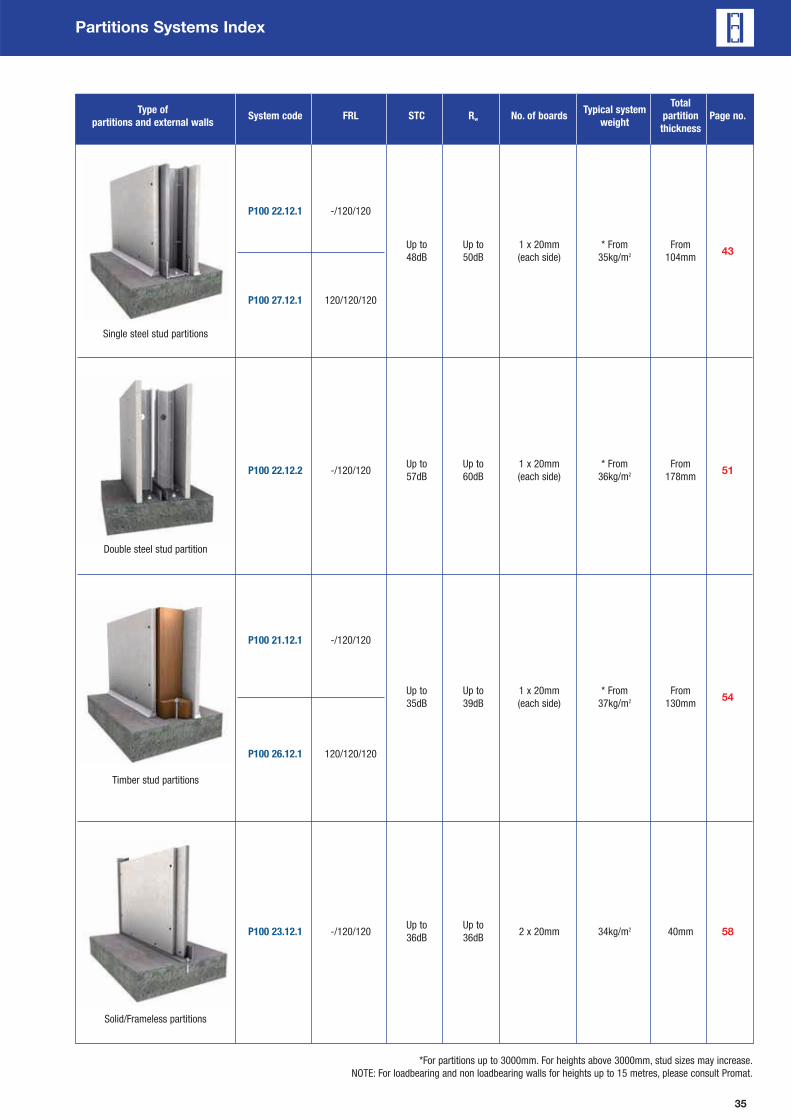
35
Single steel stud partitions
Double steel stud partition
Partitions Systems Index
Solid/Frameless partitions
Timber stud partitions
Type of Typical systemTotal
partitions and external wallsSystem code FRL STC Rw No. of boards
weightpartition Page no.
thickness
P100 22.12.1 -/120/120
Up to Up to 1 x 20mm * From From43
48dB 50dB (each side) 35kg/m2 104mm
P100 27.12.1 120/120/120
P100 22.12.2 -/120/120Up to Up to 1 x 20mm * From From
5157dB 60dB (each side) 36kg/m2 178mm
P100 21.12.1 -/120/120
Up to Up to 1 x 20mm * From From54
35dB 39dB (each side) 37kg/m2 130mm
P100 26.12.1 120/120/120
P100 23.12.1 -/120/120Up to Up to
2 x 20mm 34kg/m2 40mm 5836dB 36dB
*For partitions up to 3000mm. For heights above 3000mm, stud sizes may increase.
NOTE: For loadbearing and non loadbearing walls for heights up to 15 metres, please consult Promat.

36
Partitions General Information
Introduction
Partitions and external walls are used to separate buildings, enclose
compartments and contain fire to provide a barrier to the passage
of fire from one side to the other and are able to satisfy each of the
relevant fire resistant criteria (integrity, insulation and, if the wall is
loadbearing, load bearing capacity) from either side for the
prescribed period. The application of partition and external wall
systems using Promat boards covers both non loadbearing and
loadbearing in commercial, industrial, institutional, residential and
high-rise constructions, or in the restoration of existing buildings.
Promat’s internal partition systems require less material to achieve
similar fire resistant level when compared to the industry average
wallboard partition systems. The single layer board application
leads to simplified construction methods over other equivalents
hence increased productivity and reduced overall installation cost.
These partition and external wall systems have been developed by
Promat International (Asia Pacific) Ltd. to satisfy standard
requirements for intended applications. Such considerations include:
Time & Cost Effectiveness
Single layer application reduces installation cost and time
compared to traditional wallboard partitions.
Slim Walls
Partitions can be as thin as 40mm.
Lightweight
Lighter loads on structures compared to industry average wallboard
partition systems for equivalent fire resistance.
Thermal Resistance
Excellent thermal resistance performance.
Impact Resistant
PROMATECT®-100 partition systems have been tested and
assessed for impact and static loading to satisfy specification CI.8
of the Building Code of Australia (BCA 2006). PROMATECT®-H
partition systems have been tested for resistance to impact, stiffness
and robustness in accordance with the criteria of BS5234: Part 2.
Acoustic Performance
Tested and assessed to a range of standards, including ISO140-3
1995, ISO717-1 1996, AS1191 2002, AS/NZS 1276.1, BS5821 1984
and BS2750: Part 3: 1980, to meet the needs of industry. Please
refer to pages 41 and 42 for details.
Fire Resistance Performance
Promat partitions and external wall systems have been extensively
tested and assessed in accordance with BS476: Part 22 and
AS1530: Part 4 to satisfy the integrity, insulation and where
applicable loadbearing capacity (structural adequacy) criteria.
General Design Considerations
The following points are some of the factors which should be
considered when determining the correct specification to ensure
a partition or external wall will provide the required design
performance under both fire and ambient conditions. Further advice
can be obtained from the local Promat office.
1. Studwork Design
The design of studwork should be adequate for the height of the
partition. The studwork details given in the following specifications
will be suitable up to the maximum heights stated. For greater
heights the dimension of the framing members could change
depending on the factors such as movement and deflection and
local approvals. Larger or more frequent frame sections will often
improve the fire and structural performance.
The studwork shall be appropriately designed for the applied loads,
e.g. wind load, and where applicable structural load in the case of
load bearing systems. The framing for the partition systems must be
securely fixed to a substrate that has an equal or greater fire
performance than the designed partition. All fixings must be non-
combustible and must be those listed in the approval documents.
The design shall be in accordance with the relevant Australian,
British and/or International Standards.
2. Non Loadbearing Partitions
Non loadbearing partitions and external wall systems using Promat
boards can be generally divided into framing systems consisting of
steel or timber studs and solid partitions. For steel stud systems,
selection of suitable stud size shall be in accordance with the
maximum partition height given in the stud selection tables. The
partition systems in the following pages, where stated, are designed
for lateral loads of up to 0.25kPa using the composite action of the
frame and boarding.
3. Loadbearing Partitions
Loadbearing capacity of featured partition systems in this
handbook are calculated in accordance with BS5950-8: 2003 and
AS4600: 1996 for load cases defined by AS1170: 2002. The
maximum load bearing capacity is given in kN for a given
partition height taking into account the reduction in steel strength at
elevated temperature.
Studs are located at 600mm maximum centres with noggings as
detailed in Studs Table on page 50.
Loads considered in this manual are for axial compression only.
Wind and other loads have not been taken into consideration.
For further information on these loads, please contact Promat
Technical Department.
4. Deflection
Where differential movement is expected between the floor or beam
above the construction, and/or the floor below, it is generally
advisable to incorporate a deflection head track to ensure undue
stress is not placed upon the partition. This also allows for the
sagging and deflection a floor or structural steel beam will suffer
under fire conditions. Even concrete floors will suffer considerable
deflection under fire if exposed for any considerable duration.
Some form of movement joint is also required to allow for the
expansion of the studs under fire conditions. A partition will also
bow in its centre. As the wall bows, it will naturally get shorter. For
this reason alone, use should be made of a top track with long side
legs. This will allow the stud to bow and as a result drop down,
without the studs dropping out of the head track.
5. Movement Joint
Movement stress from dimensional changes due to varying
temperature or moisture conditions can cause cracking and other
symptoms of distress in partitions. Other external forces such as
impact or vibration can directly affect the structural movement of
partitions. This movement can be controlled through a variety of
design techniques such as introducing perimeter relief and slip
connections to reduce the transfer of stress from the structure to
other building sub-elements and/or through the use of expansion
joints, control joints and construction joints.
In a partition, expansion joints are needed when the partition abuts
a rigid mass. A vertical movement joint should be located at
maximum 10m centres in long runs of partition. However, by
introducing a control joint into a fire-rated partition, it does create
an opening for flame and temperature transmission and therefore
has to be properly treated with approved fire-stopping material.
Please refer to page 86 for further details on movement joints.
Continued on following page

37
Partitions General Information
Steel Frame Components
Board Fixing
Promat boards may be installed horizontally or vertically.
For steel stud partition system, joints in the boards must be
staggered between either side of the framing with all the joints
located at a framing member. The boards may be fixed to the studs
using No.8 Bugle head self drilling and self-tapping screws of a
length appropriate for the board thickness. Needle point screws are
normally used to fix boards to light gauge steel frames up to
0.8mm. Drill point screws are generally appropriate for heavy gauge
steel frames from 0.8mm to 2.0mm.
For solid partition system, joints between the adjacent boards must
be staggered by at least 300mm. First layer of the boards are to be
fixed to the perimeter angle with 35mm long x No.8 self-drilling and
self-tapping screws. The subsequent layer of the boards is to be
stitched to the preceding layer with 40mm long x No.10 laminating
screws, as well as fixing to the perimeter framing.
When a timber frame is used, Promat boards are fixed to the
framework using No. 6 wood screws of a length appropriate for the
board thickness at maximum 250mm centres, a minimum of 12mm
from the board edge. Minimum edge distance to fasteners and the
maximum spacing between screw must be maintained. Please refer
to system detail for screws spacing requirements.
Internal and external corners may be set using a perforated
metal corner bead fixed to the board linings at not more than
500mm centres.
Components Selection
Construction of Promat fire rated steel stud partitions can be achieved using Rondo stud and track components. Other steel components of
equivalent performance can of course be used but it is the responsibility of the manufacturer of the component to substantiate equivalent
performance with the recommended component.
Tracks At Deflection Head & Floor
The main function of the ceiling and floor tracks is to hold the studs
in position until the board is fitted. They provide a friction fit of
the studs and also act as a slip joint to allow for any movement in
the structure.
The track sections basically come in two profiles. A standard track
has a nominal 32mm flange while the deflection head track has a
nominal 50mm flange. However, head tracks with wider flange are
available but they have to be specially designed for instances
where clearance for expansion at the head track exceeds 20mm.
No clearance for expansion is applicable at the head track for a loadbearing partition.
Track sections should be fixed at maximum 600mm intervals to the supporting structure. Fixings should be located not more than 100mm from
either end of the track section.
Bottom track
Vertical stud
Nogging
Head track
6. Caulking & Service Penetrations
To maintain the fire performance, and where applicable the acoustic
performance of the partition system, gaps at perimeter must be
appropriately filled with suitable caulking material. PROMASEAL®
AN Acrylic Sealant or other tested fire and acoustic rated material
of equivalent or better performance must be used.
Care needs to be taken in detailing a suitable fire-stopping system
around any penetration of the partition by services to ensure a) the
fire-stopping material remains in situ and b) fire and smoke do not
penetrate the partition.
Allowance should be made for thermal movement of the services in
both ambient and fire conditions to ensure loads are not applied to
the partition. Some examples of service penetrations include
electrical cables, conduits or wires, switches and power outlets,
plastic and metal pipes, air-conditioning and ventilation ductwork.
Further guidance on the sealing of service penetrations can be
obtained in Chapter 5 of this handbook.
7. Fire Doors & Glazing
Tested or assessed door and/or glazed assemblies should always
be used. All and any doors or glazed elements with a fire resistant
wall should be shown, by fully compliant testing within to the
appropriate standard, to be capable of providing at least an equal
fire performance to the wall itself. This means fire doors should be
tested in lightweight partition systems, not just in masonry. In most
cases additional framework will be required to prevent loads being
applied to the partition. Careful detailing is needed around the
perimeter of any door or glazed assembly. Further guidance on the
detailing at fire doors and glazing can be obtained on page 83.
8. Partition Junction
Care must be taken to ensure that partition corner junctions and
intersections are stable for both fire and ambient conditions.
Framing at these locations has to be mechanically fastened
together. Further guidance on the detailing at these junctions can
be obtained on pages 87 and 88.
General Design Considerations Continued from previous page
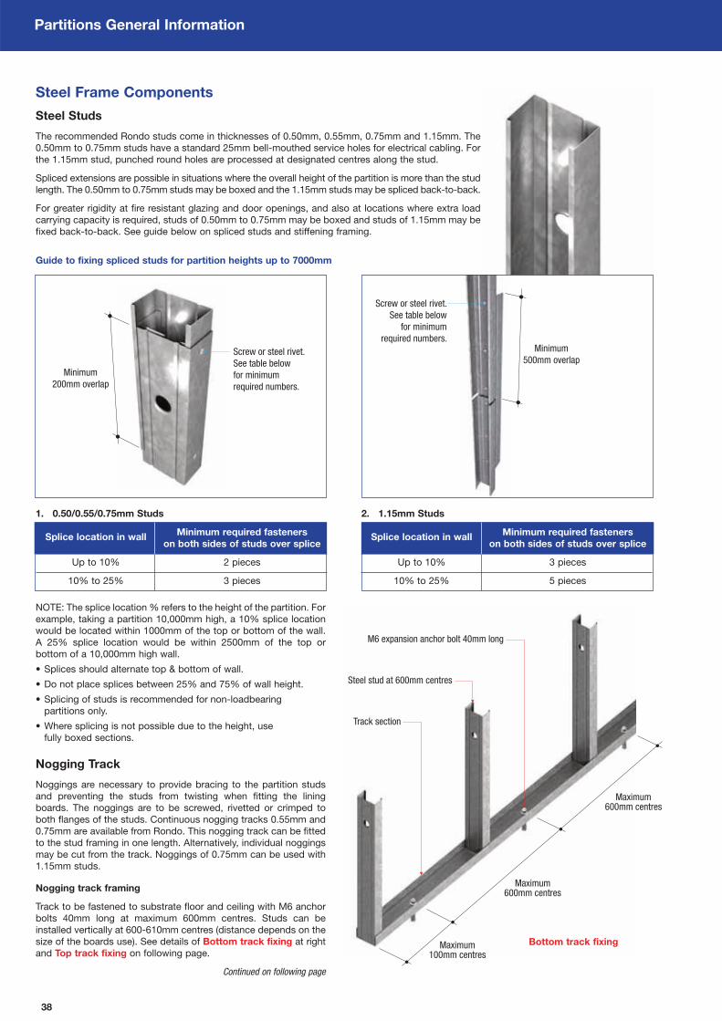
38
Partitions General Information
Steel Frame Components
Steel Studs
The recommended Rondo studs come in thicknesses of 0.50mm, 0.55mm, 0.75mm and 1.15mm. The
0.50mm to 0.75mm studs have a standard 25mm bell-mouthed service holes for electrical cabling. For
the 1.15mm stud, punched round holes are processed at designated centres along the stud.
Spliced extensions are possible in situations where the overall height of the partition is more than the stud
length. The 0.50mm to 0.75mm studs may be boxed and the 1.15mm studs may be spliced back-to-back.
For greater rigidity at fire resistant glazing and door openings, and also at locations where extra load
carrying capacity is required, studs of 0.50mm to 0.75mm may be boxed and studs of 1.15mm may be
fixed back-to-back. See guide below on spliced studs and stiffening framing.
Guide to fixing spliced studs for partition heights up to 7000mm
NOTE: The splice location % refers to the height of the partition. For
example, taking a partition 10,000mm high, a 10% splice location
would be located within 1000mm of the top or bottom of the wall.
A 25% splice location would be within 2500mm of the top or
bottom of a 10,000mm high wall.
• Splices should alternate top & bottom of wall.
• Do not place splices between 25% and 75% of wall height.
• Splicing of studs is recommended for non-loadbearing
partitions only.
• Where splicing is not possible due to the height, use
fully boxed sections.
Nogging Track
Noggings are necessary to provide bracing to the partition studs
and preventing the studs from twisting when fitting the lining
boards. The noggings are to be screwed, rivetted or crimped to
both flanges of the studs. Continuous nogging tracks 0.55mm and
0.75mm are available from Rondo. This nogging track can be fitted
to the stud framing in one length. Alternatively, individual noggings
may be cut from the track. Noggings of 0.75mm can be used with
1.15mm studs.
Nogging track framing
Track to be fastened to substrate floor and ceiling with M6 anchor
bolts 40mm long at maximum 600mm centres. Studs can be
installed vertically at 600-610mm centres (distance depends on the
size of the boards use). See details of Bottom track fixing at right
and Top track fixing on following page.
Continued on following page
1. 0.50/0.55/0.75mm Studs
Splice location in wallMinimum required fasteners
on both sides of studs over splice
Up to 10% 2 pieces
10% to 25% 3 pieces
2. 1.15mm Studs
Splice location in wallMinimum required fasteners
on both sides of studs over splice
Up to 10% 3 pieces
10% to 25% 5 pieces
Screw or steel rivet.
See table below
for minimum
required numbers.
Minimum
200mm overlap
Screw or steel rivet.
See table below
for minimum
required numbers.Minimum
500mm overlap
M6 expansion anchor bolt 40mm long
Steel stud at 600mm centres
Track section
Maximum600mm centres
Maximum600mm centres
Maximum100mm centres
Bottom track fixing

39
Partitions General Information
Rondo lippedchannel studat 600mm or
625mm centres
Head track structurallydesigned in accordancewith BS5950 or AS4600
for given gap size
MinimumD x 3 times
Maximum50mm
D
Nogging track framing
Below are the options for different methods of providing noggings.
Steel stud as the horizontal track
• Studs to be cut to a short length and screwed
in between each of the vertical studs.
• Cut the base of the track
leaving two short overlapping
flanges either side. Insert
between the vertical steel
studs and fix through the
studs into the vertical studs
either side, using steel (not
aluminium) rivets or screws.
• All horizontal joints of the
boards will be fixed to
the noggings.
Steel channel as the horizontal noggings
• Steel channel to be cut in
length and screw fixed to
the both sides of the
vertical studs.
• All horizontal joints of the
boards will be fixed to
the nogging.
Board strips at the horizontal joints Top track fixing
• Cover fillets minimum
75mm wide cut from
main lining boards. Fix
board to board using
stitching screws of a
length appropriate to
the board thickness,
at nominal 200mm
maximum centres. Not
required for the majority
of PROMATECT® 100
wall systems.
• All horizontal joints to
be backed by board
strips.
Steel Frame Components Continued from previous page

40
Partitions General Information
Timber Frame Components
Timber Frame
Timber has very good performance in fire. Timber does burn but at
a relatively slow and to a predictable depth known as the charring
rate. This is one major advantage of using timber over steel
because the fire resistance of timber elements of construction may
be calculated based on a predictable charring rate.
Timber also has a very low thermal conductivity value and hence
does not heat uniformly. Therefore, timber material a few millimetres
inside the burning zone is just warm. The formation of a self
insulating char resists further heat penetration.
Unlike materials with a high thermal conductivity materials such as
steel, there are less problems associated with expansion or loss of
strength over the whole section in timber. This means that, in some
instances timber retains its structural integrity better than steel.
There are many different types of timbers and they all char at
varying rates. Higher density timbers char more slowly than those
of lower density. Denser hardwoods used for structural purposes,
such as jarrah, teak, keruing and greenheart, char at a rate of
15mm in 30 minutes. Lower density (< 650kg/m3) softwood timbers
such as Western red cedar or Pinus Radiata is estimated at a
charring rate of 25mm in 30 minutes.
Timber Studs & Cross Noggings
The frame used in the timber stud partitions typically consists of
90mm deep x 45mm wide softwood timber. The fire performance of
the partition system accounts for the loss of the timber section due
to charring effect without compromising the fire performance of the
partition.
Where the boards are to be installed with their long edges vertical,
the studs are located at 600mm maximum centres (dependent on
board width) with cross noggings at 1250mm centres. Where
the boards are to be installed with their long edges horizontal, the
studs are located at 600mm centres with cross noggings at
1250mm centres.
The cross noggings may be fixed to the studs using nails or
woodscrews of at least 100mm long in a manner shown in Fixing
method 1 or 2 at right. Either method can be adopted to fix the
cross noggings.
Top & Floor Plates
The top and floor plates are to be of the same material and
dimensions as the studs. They are to be secured to the surrounding
structure with at least M6 x 100mm long anchors at nominal
600mm centres with the drilled depth into the concrete structure of
at least 40mm. Polyamide nylon anchor sleeves may be allowed for
use with timber framing.
The vertical studs may be fixed to the top and floor plates using
either nails or woodscrews of at least 100mm long in a manner
shown in Floor plate fixing at bottom right.
Loadbearing Partition
Where a partition is loadbearing, the required size of the stud shall
be calculated by a suitably qualified structural engineer. Care
should be taken to ensure that the loadbearing partition has been
designed to resist all applied loads and in accordance with BS5268:
Part 4, AS1720: Part 1 or AS1684. Generally, the fire performance
and the load carrying capacity will improve by increasing the cross-
sectional dimensions of the timber elements and/or decreasing the
stud spacing.
Fixing method 1
Fixing method 2
Floor plate fixing
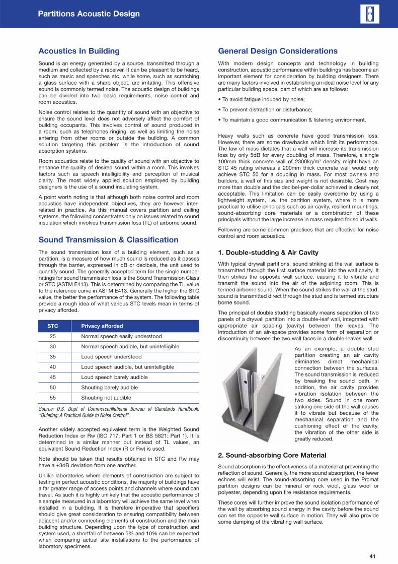
41
Partitions Acoustic Design
Acoustics In Building
Sound is an energy generated by a source, transmitted through a
medium and collected by a receiver. It can be pleasant to be heard,
such as music and speeches etc, while some, such as scratching
a glass surface with a sharp object, are irritating. This offensive
sound is commonly termed noise. The acoustic design of buildings
can be divided into two basic requirements, noise control and
room acoustics.
Noise control relates to the quantity of sound with an objective to
ensure the sound level does not adversely affect the comfort of
building occupants. This involves control of sound produced in
a room, such as telephones ringing, as well as limiting the noise
entering from other rooms or outside the building. A common
solution targeting this problem is the introduction of sound
absorption systems.
Room acoustics relate to the quality of sound with an objective to
enhance the quality of desired sound within a room. This involves
factors such as speech intelligibility and perception of musical
clarity. The most widely applied solution employed by building
designers is the use of a sound insulating system.
A point worth noting is that although both noise control and room
acoustics have independent objectives, they are however inter-
related in practice. As this manual covers partition and ceiling
systems, the following concentrates only on issues related to sound
insulation which involves transmission loss (TL) of airborne sound.
Sound Transmission & Classification
The sound transmission loss of a building element, such as a
partition, is a measure of how much sound is reduced as it passes
through the barrier, expressed in dB or decibels, the unit used to
quantify sound. The generally accepted term for the single number
ratings for sound transmission loss is the Sound Transmission Class
or STC (ASTM E413). This is determined by comparing the TL value
to the reference curve in ASTM E413. Generally the higher the STC
value, the better the performance of the system. The following table
provide a rough idea of what various STC levels mean in terms of
privacy afforded.
STC Privacy afforded
25 Normal speech easily understood
30 Normal speech audible, but unintelligible
35 Loud speech understood
40 Loud speech audible, but unintelligible
45 Loud speech barely audible
50 Shouting barely audible
55 Shouting not audible
Source: U.S. Dept of Commerce/National Bureau of Standards Handbook.
“Quieting: A Practical Guide to Noise Control”.
Another widely accepted equivalent term is the Weighted Sound
Reduction Index or Rw (ISO 717: Part 1 or BS 5821: Part 1). It is
determined in a similar manner but instead of TL values, an
equivalent Sound Reduction Index (R or Rw) is used.
Note should be taken that results obtained in STC and Rw may
have a ±3dB deviation from one another.
Unlike laboratories where elements of construction are subject to
testing in perfect acoustic conditions, the majority of buildings have
a far greater range of access points and channels where sound can
travel. As such it is highly unlikely that the acoustic performance of
a sample measured in a laboratory will achieve the same level when
installed in a building. It is therefore imperative that specifiers
should give great consideration to ensuring compatibility between
adjacent and/or connecting elements of construction and the main
building structure. Depending upon the type of construction and
system used, a shortfall of between 5% and 10% can be expected
when comparing actual site installations to the performance of
laboratory specimens.
General Design Considerations
With modern design concepts and technology in building
construction, acoustic performance within buildings has become an
important element for consideration by building designers. There
are many factors involved in establishing an ideal noise level for any
particular building space, part of which are as follows:
• To avoid fatigue induced by noise;
• To prevent distraction or disturbance;
• To maintain a good communication & listening environment.
Heavy walls such as concrete have good transmission loss.
However, there are some drawbacks which limit its performance.
The law of mass dictates that a wall will increase its transmission
loss by only 5dB for every doubling of mass. Therefore, a single
100mm thick concrete wall of 2300kg/m3 density might have an
STC 45 rating whereas a 200mm thick concrete wall would only
achieve STC 50 for a doubling in mass. For most owners and
builders, a wall of this size and weight is not desirable. Cost may
more than double and the decibel-per-dollar achieved is clearly not
acceptable. This limitation can be easily overcome by using a
lightweight system, i.e. the partition system, where it is more
practical to utilise principals such as air cavity, resilient mountings,
sound-absorbing core materials or a combination of these
principals without the large increase in mass required for solid walls.
Following are some common practices that are effective for noise
control and room acoustics.
1. Double-studding & Air Cavity
With typical drywall partitions, sound striking at the wall surface is
transmitted through the first surface material into the wall cavity. It
then strikes the opposite wall surface, causing it to vibrate and
transmit the sound into the air of the adjoining room. This is
termed airborne sound. When the sound strikes the wall at the stud,
sound is transmitted direct through the stud and is termed structure
borne sound.
The principal of double studding basically means separation of two
panels of a drywall partition into a double-leaf wall, integrated with
appropriate air spacing (cavity) between the leaves. The
introduction of an air-space provides some form of separation or
discontinuity between the two wall faces in a double-leaves wall.
As an example, a double stud
partition creating an air cavity
eliminates direct mechanical
connection between the surfaces.
The sound transmission is reduced
by breaking the sound path. In
addition, the air cavity provides
vibration isolation between the
two sides. Sound in one room
striking one side of the wall causes
it to vibrate but because of the
mechanical separation and the
cushioning effect of the cavity,
the vibration of the other side is
greatly reduced.
2. Sound-absorbing Core Material
Sound absorption is the effectiveness of a material at preventing the
reflection of sound. Generally, the more sound absorption, the fewer
echoes will exist. The sound-absorbing core used in the Promat
partition designs can be mineral or rock wool, glass wool or
polyester, depending upon fire resistance requirements.
These cores will further improve the sound isolation performance of
the wall by absorbing sound energy in the cavity before the sound
can set the opposite wall surface in motion. They will also provide
some damping of the vibrating wall surface.

42
Partitions Acoustic Design
General Design Considerations
3. Treatment To Flanking Paths
When working with acoustically rated systems, it is critical that strict
attention be paid to construction and detailing. The acoustic
integrity of a system can be influenced by the combination of
elements that make up the system. Single leaf and uninsulated
systems are particularly dependent on high quality of installation.
For example, if there is a gap of 5mm wide around the perimeter of
an STC 45 rated wall of 3m x 3m, the actual performance would
degrade to some STC 30. Therefore, to make acoustically rated
partitions effective, they must be airtight. Any path for air also
means there is a path for sound. In order to achieve the designed
STC rating closely, the following factors must also be taken
into account:
• Sound paths, e.g. windows, doors, floors and ceilings;
• Penetrations through walls, even above ceilings or below
floorings, must be sealed;
• Stagger the joints between multiple layers of wall boards
or ceiling linings;
• Do not use power points back to back on either side of a wall;
• Openings for return air in ceiling plenum systems must be
strictly controlled.
4. Wall & Floor Intersections
A good acoustical partition is only as good as its joint or
intersection at wall and floor, like a chain and its weakest link. If this
joint or intersection is not treated properly, the acoustical value may
be lost. Many joint defects from flanking paths allow sound to travel
via air gaps through the structure.
Acoustical sealants are the simplest means to provide a permanent
air-tight seal. They are made from materials that are permanently
elastic which will allow floor or wall materials to move, as they are
prone to do because of expansion and contraction or outside forces
such as structural movement. A permanent air-tight seal is the
most effective way to maintain the acoustical integrity of the wall.
Regardless of which system is employed, all openings, cracks and
material joints should be made air-tight with a permanently elastic
acoustical sealant.
System Selection Guide
As sound insulation requirements may vary from country to country,
the table below suggests acoustic values for some typical partition
installations, unless otherwise specified by the architects. Please
consult Promat for more information.
9
12
3
5 4
8 6
1
10
7
Some sources of sound leakage
1 Air leaks through gaps or cracks
2 Doors
3 Light weight panels above doors
4 Electrical outlets and service pipes
5 Partition performance
6 Sound transmission via suspended ceilings
or partitions
7 Common floor heating duct
8 Common ventilation system without
sound absorbents treatment
9 Lightweight mullion or partition closer
10 Appliances
STC ratingApplications for separating
Minimum Average Luxury
45dB 50dB 55dB Bedroom to bedroom
50dB 55dB 60dB Bedroom to living room
50dB 55dB 60dB Bedroom to lobby
45dB 50dB 55dB Office to office
40dB 45dB 50dB Office to general area
45dB 50dB 55dB Office to conference room
45dB 50dB 55dB Office to washroom
40dB 45dB 50dB Conference room to general area
40dB 45dB 50dB Conference room to conference room
45dB – – Classroom to classroom
55dB – – Classroom to shop
45dB – – Classroom to recreation area
60dB – – Classroom to music room
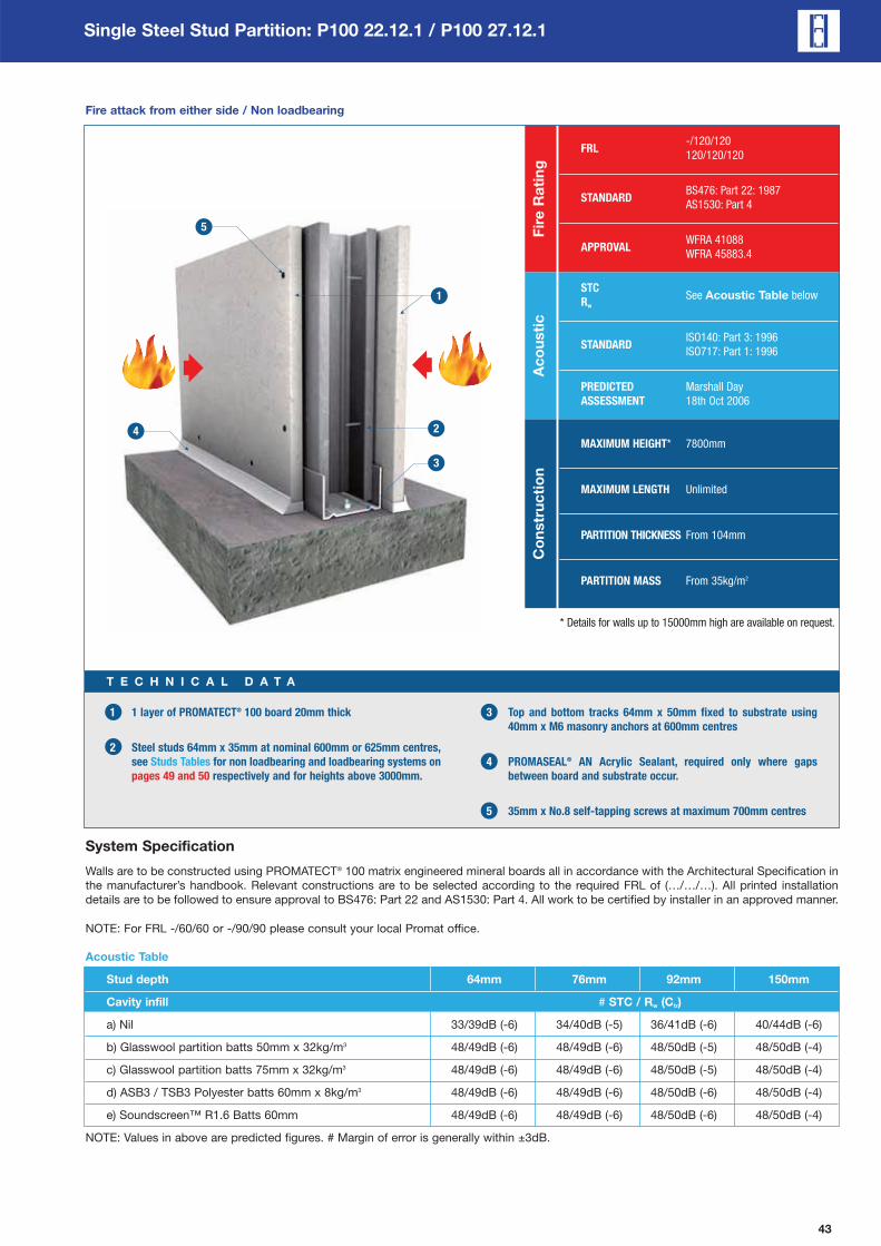
43
Single Steel Stud Partition: P100 22.12.1 / P100 27.12.1
FRL-/120/120
120/120/120
STANDARDBS476: Part 22: 1987
AS1530: Part 4
APPROVALWFRA 41088
WFRA 45883.4
Fir
e R
ati
ng
STCSee Acoustic Table below
Rw
STANDARDISO140: Part 3: 1996
ISO717: Part 1: 1996
PREDICTED Marshall Day
ASSESSMENT 18th Oct 2006
Ac
ou
sti
c
1 1 layer of PROMATECT® 100 board 20mm thick
2 Steel studs 64mm x 35mm at nominal 600mm or 625mm centres,
see Studs Tables for non loadbearing and loadbearing systems on
pages 49 and 50 respectively and for heights above 3000mm.
3 Top and bottom tracks 64mm x 50mm fixed to substrate using
40mm x M6 masonry anchors at 600mm centres
4 PROMASEAL® AN Acrylic Sealant, required only where gaps
between board and substrate occur.
5 35mm x No.8 self-tapping screws at maximum 700mm centres
T E C H N I C A L D A T A
System Specification
Walls are to be constructed using PROMATECT® 100 matrix engineered mineral boards all in accordance with the Architectural Specification in
the manufacturer’s handbook. Relevant constructions are to be selected according to the required FRL of (…/…/…). All printed installation
details are to be followed to ensure approval to BS476: Part 22 and AS1530: Part 4. All work to be certified by installer in an approved manner.
NOTE: For FRL -/60/60 or -/90/90 please consult your local Promat office.
Acoustic Table
Stud depth 64mm 76mm 92mm 150mm
Cavity infill # STC / Rw (Ctr)
a) Nil 33/39dB (-6) 34/40dB (-5) 36/41dB (-6) 40/44dB (-6)
b) Glasswool partition batts 50mm x 32kg/m3 48/49dB (-6) 48/49dB (-6) 48/50dB (-5) 48/50dB (-4)
c) Glasswool partition batts 75mm x 32kg/m3 48/49dB (-6) 48/49dB (-6) 48/50dB (-5) 48/50dB (-4)
d) ASB3 / TSB3 Polyester batts 60mm x 8kg/m3 48/49dB (-6) 48/49dB (-6) 48/50dB (-6) 48/50dB (-4)
e) Soundscreen™ R1.6 Batts 60mm 48/49dB (-6) 48/49dB (-6) 48/50dB (-6) 48/50dB (-4)
NOTE: Values in above are predicted figures. # Margin of error is generally within ±3dB.
Fire attack from either side / Non loadbearing
MAXIMUM HEIGHT* 7800mm
MAXIMUM LENGTH Unlimited
PARTITION THICKNESS From 104mm
PARTITION MASS From 35kg/m2
Co
nstr
uc
tio
n
* Details for walls up to 15000mm high are available on request.

44
Single Steel Stud Partition: P100 22.12.1 / P100 27.12.1
Maximum
300mm
Up to
2500mm
Vertical sheeting (below 3000mm) / Non loadbearing and loadbearing
1 For FRL of -/120/120 and 120/120/120
1 layer of PROMATECT® 100 board, 20mm thick at each side of wall.
2 Cavity infill if required to improve acoustic or thermal insulation
3 Allow appropriate clearance at top track, no clearance at top
track required for loadbearing partition. See Studs Tables on
pages 49 and 50.
4 Caulk all perimeter gaps with PROMASEAL® AN Acrylic Sealant to
achieve stated fire and/or acoustic performance
5 Vertical studs at 600mm centres, see Studs Tables on pages 49
and 50 for heights above 3000mm.
See pages 38 and 39 for bottom and top track fixings; pages 84 to 88
for details of wall head, wall base, wall movement joints and
wall junction.
T E C H N I C A L D A T A

45
Single Steel Stud Partition: P100 22.12.1 / P100 27.12.1
Maximum
300mm
Up to
7800mm
Vertical sheeting (above 3000mm) / Non loadbearing and loadbearing
1 For FRL of -/120/120 and 120/120/120
1 layer of PROMATECT® 100 board, 20mm thick at each side of wall.
2 Cavity infill if required to improve acoustic or thermal insulation
3 Allow appropriate clearance at top track, no clearance at top
track required for loadbearing partition. See Studs Tables on
pages 49 and 50.
4 Caulk all perimeter gaps with PROMASEAL® AN Acrylic Sealant to
achieve stated fire and/or acoustic performance
5 Vertical studs at 600mm centres, see Studs Tables on pages 49
and 50 for heights above 3000mm.
6 Nogging at all horizontal board joints
See pages 38 and 39 for bottom and top track fixings; pages 84 to 88
for details of wall head, wall base, wall movement joints and
wall junction.
T E C H N I C A L D A T A
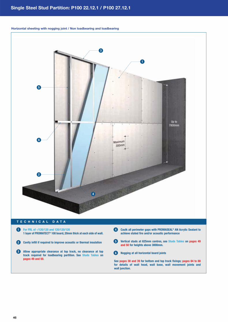
46
Single Steel Stud Partition: P100 22.12.1 / P100 27.12.1
Up to
7800mm
Maximum
300mm
Horizontal sheeting with nogging joint / Non loadbearing and loadbearing
1 For FRL of -/120/120 and 120/120/120
1 layer of PROMATECT® 100 board, 20mm thick at each side of wall.
2 Cavity infill if required to improve acoustic or thermal insulation
3 Allow appropriate clearance at top track, no clearance at top
track required for loadbearing partition. See Studs Tables on
pages 49 and 50.
4 Caulk all perimeter gaps with PROMASEAL® AN Acrylic Sealant to
achieve stated fire and/or acoustic performance
5 Vertical studs at 625mm centres, see Studs Tables on pages 49
and 50 for heights above 3000mm.
6 Nogging at all horizontal board joints
See pages 38 and 39 for bottom and top track fixings; pages 84 to 88
for details of wall head, wall base, wall movement joints and
wall junction.
T E C H N I C A L D A T A

47
Single Steel Stud Partition: P100 22.12.1 / P100 27.12.1
Up to
7800mm
Maximum
300mm
Horizontal sheeting with strip joint / Non loadbearing and loadbearing
1 For FRL of -/120/120 and 120/120/120
1 layer of PROMATECT® 100 board, 20mm thick at each side of wall.
2 Cavity infill if required to improve acoustic or thermal insulation
3 Allow appropriate clearance at top track, no clearance at top
track required for loadbearing partition. See Studs Tables on
pages 49 and 50.
4 Caulk all perimeter gaps with PROMASEAL® AN Acrylic Sealant to
achieve stated fire and/or acoustic performance
5 Vertical studs at 625mm centres, see Studs Tables on pages 49
and 50 for heights above 3000mm.
6 20mm thick PROMATECT® 100 cover strips at horizontal
board joints
See pages 38 and 39 for bottom and top track fixings; pages 84 to 88
for details of wall head, wall base, wall movement joints and
wall junction.
T E C H N I C A L D A T A

48
Single Steel Stud Partition: P100 22.12.1 / P100 27.12.1
Up to
7800mm
Maximum
300mm
Horizontal sheeting with channel joint / Non loadbearing and loadbearing
1 For FRL of -/120/120 and 120/120/120
1 layer of PROMATECT® 100 board, 20mm thick at each side of wall.
2 Cavity infill if required to improve acoustic or thermal insulation
3 Allow appropriate clearance at top track, no clearance at top
track required for loadbearing partition. See Studs Tables on
pages 49 and 50.
4 Caulk all perimeter gaps with PROMASEAL® AN Acrylic Sealant to
achieve stated fire and/or acoustic performance
5 Vertical studs at 625mm centres, see Studs Tables on pages 49
and 50 for heights above 3000mm.
6 Fixing channel 100mm x 10mm x 0.9mm thick
See pages 38 and 39 for bottom and top track fixings; pages 84 to 88
for details of wall head, wall base, wall movement joints and
wall junction.
T E C H N I C A L D A T A

49
Single Steel Stud Partition: P100 22.12.1
Architectural Specification
The following are standard Architectural Specifications for internal partition systems using PROMATECT® 100. The designer must determine the
suitability of the design to the application and requirements before undertaking or constructing any works relating to the specifications and
where in doubt should obtain the advice of a suitably qualified engineer.
Fire Attack From Either Side / NON LOADBEARING
120 minutes of fire rating, integrity and insulation in accordance with the criteria of BS476: Part 22: 1987 and AS1530: Part 4. Lateral load
of up to 0.25kPa.
Acoustic Performance
The partition system shall have a Weighted Sound Reduction Index of at least Rw 39.
Supporting Structure
Care should be taken that any structural element by which the partition system is supported, e.g. steel stud or perimeter steel channel, has
fire resistance of at least 120 minutes.
Lining Boards
Single layer on either side of 20mm PROMATECT® 100 matrix engineered mineral boards as manufactured by Promat International (Asia
Pacific) Ltd. All joints to be coincident with steel framing or backed by PROMATECT® 100 cover fillet. Standard board dimensions 1200mm
x 2500mm x 20mm.
Fixing
Galvanised steel frame made of ceiling and floor tracks will be secured to the floor, ceiling and walls with 40mm x M6 masonry anchors at
600mm centres. Vertical steel studs are then friction fitted into the tracks at 600mm centres for boards to be installed with long edge
vertically and at 625mm centres for boards to be installed with long edge horizontally. Adequate clearance for vertical expansion will be
allowed at the ceiling/top track. No clearance is necessary at the bottom track. See table below for steel size and clearance at top track
for given partition height.
Horizontal noggings, cut out of the steel track material will be friction fitted between the steel studs to coincide with horizontal joints
between boards.
Studs Table
Partitions lined with 20mm PROMATECT® 100 (studs at 600mm centres, 0.25kPa, minimum two rows of nogging).
Maximum Stud Minimum MaximumTop track
Clearance at
partition height depth stud thickness partition thickness top track
3000mm 64mm 0.5mm 104mm 64 x 50 x 0.75mm 20mm
3600mm 64mm 0.75mm 104mm Special Design* 24mm
4000mm 64mm 1.15mm 104mm Special Design* 29mm
3500mm 76mm 0.55mm 116mm Special Design* 23mm
4100mm 76mm 0.75mm 116mm Special Design* 28mm
4850mm 76mm 1.15mm 116mm Special Design* 33mm
3733mm 92mm 0.55mm 132mm Special Design* 25mm
4700mm 92mm 0.75mm 132mm Special Design* 32mm
5600mm 92mm 1.15mm 132mm Special Design* 38mm
5867mm 150mm 0.75mm 190mm Special Design* 39mm
7800mm 150mm 1.15mm 190mm Special Design* 50mm
*Top tracks are designed or tested in accordance with AS4600: 1996 for a clearance between stud and top track as shown above.
Please consult Promat Technical Department for further details.
20mm thick PROMATECT® 100 boards will be screw-fixed to the frame with 35mm x No.8 self-tapping screws at maximum 300mm centres.
Tests & Standards
Along with all material tests the complete system along with the framing is tested in accordance with the criteria of AS1530: Part 4. The
partition system should meet the requirements specified in BCA 2006 Specification C1.8 for static, dynamic and indentation load tests as
specified under Clause 3.1, 3.2 and 3.4.
Jointing
Plain butt joints between machined edges of boards. (1)
Joints filled in preparation for painting. (2)
Joints filled and taped in preparation for decoration. (3)
Follow-on Trades
Surface of boards to be prepared for painting/plastering/tiling(4) in accordance with manufacturer’s recommendations.
NOTES:
• (1), (2), (3), (4) delete as appropriate.
• Perimeter gaps will be filled with fire resistant PROMASEAL® AN Acrylic Sealant.

50
Single Steel Stud Partition: P100 27.12.1
Architectural Specification
The following are standard Architectural Specifications for internal partition systems using PROMATECT® 100. The designer must determine the
suitability of the design to the application and requirements before undertaking or constructing any works relating to the specifications and
where in doubt should obtain the advice of a suitably qualified engineer.
Fire Attack From Either Side / LOADBEARING
120 minutes of fire rating, integrity and insulation in accordance with the criteria of BS476: Part 22: 1987 and AS1530: Part 4. Loadbearing
in accordance with AS4600: 1996 and AS1170: 2002. Lateral load of up to 0.25kPa.
Acoustic Performance
The partition system shall have a Weighted Sound Reduction Index of at least Rw 39.
Supporting Structure
Care should be taken that any structural element by which the partition system is supported, e.g. steel stud or perimeter steel channel, has
fire resistance of at least 120 minutes.
Lining Boards
Single layer each side 20mm PROMATECT® 100 matrix engineered mineral boards as manufactured by Promat International (Asia Pacific)
Ltd. All joints to be coincident with steel framing or backed by PROMATECT® 100 cover fillet. Standard board dimensions 1200mm x
2500mm x 20mm.
Fixing
Galvanised steel frame made of ceiling and floor tracks will be secured to the floor, ceiling and walls with 40mm x M6 masonry anchors at
600mm centres. Vertical steel studs are then friction fitted into the tracks at 600mm centres. See table below for stud size according to the
load capacity for a given partition height.
Horizontal nogging, cut out of the steel track material will be friction fitted between the steel studs.
Studs Table
Partitions lined with 20mm PROMATECT® 100 (studs at 600mm centres, 0.25kPa).
MinimumLoad capacity (kN) for given partition height (mm)
Stud depth stud Nogging (minimum 2 rows) Nogging per 1200mmthickness
2400mm 2700mm 3000mm 4800mm 2400mm 2700mm 3000mm 4800mm
64mm 0.5mm 0.40kN Nil Nil Nil 0.48kN 0.24kN 0.07kN Nil
64mm 0.75mm 1.58kN 1.15kN 0.68kN Nil 1.24kN 0.74kN 0.43kN Nil
64mm 1.15mm 3.76kN 2.69kN 1.87kN Nil 2.57kN 1.67kN 1.08kN Nil
76mm 0.55mm 0.95kN 0.59kN 0.31kN Nil 0.95kN 0.62kN 0.36kN Nil
76mm 0.75mm 2.20kN 1.65kN 1.18kN Nil 1.79kN 1.25kN 0.82kN Nil
76mm 1.15mm 5.17kN 4.02kN 3.03kN Nil 3.74kN 2.82kN 2.03kN 0.32kN
92mm 0.55mm 1.29kN 0.94kN 0.62kN Nil 1.25kN 0.92kN 0.64kN Nil
92mm 0.75mm 2.79kN 2.25kN 1.75kN Nil 2.32kN 1.75kN 1.28kN 0.20kN
92mm 1.15mm 6.38kN 5.26kN 4.24kN Nil 4.55kN 3.58kN 2.80kN 0.89kN
150mm 0.75mm 3.35kN 2.86kN 2.61kN 0.59kN 2.53kN 2.10kN 1.71kN 1.13kN
150mm 1.15mm 6.61kN 6.24kN 5.84kN 1.77kN 4.82kN 4.14kN 5.03kN 2.77kN
Tests & Standards
Along with all material tests the complete system along with the framing is tested in accordance with the criteria of BS476: Part 22 and
AS1530: Part 4. The load bearing capacity of the studs are calculated in accordance with BS5950: Part 8: 2003 and AS4600: 1996 for load
cases defined by AS1170: 2002. The partition system should meet the requirements specified in BCA 2006 Specification C1.8 for static,
dynamic and indentation load tests as specified under Clause 3.1, 3.2 and 3.4.
Jointing
Plain butt joints between machined edges of boards. (1)
Joints filled in preparation for painting. (2)
Joints filled and taped in preparation for decoration. (3)
Follow-on Trades
Surface of boards to be prepared for painting/plastering/tiling(4) in accordance with manufacturer’s recommendations.
NOTES:
• (1), (2), (3), (4) delete as appropriate.
• The above partition is approved for heights up to 4800mm using framing members as detailed.
• Perimeter gaps will be filled with fire resistant PROMASEAL® AN Acrylic Sealant.

51
Double Steel Stud Partition: P100 22.12.2
System Specification
Walls are to be constructed using PROMATECT® 100 matrix engineered mineral boards all in accordance with the Architectural Specification in
the manufacturer’s handbook. Relevant constructions are to be selected according to the required FRL of (-/120/120). All printed installation
details are to be followed to ensure approval to BS476: Part 22 and AS1530: Part 4. All work to be certified by installer in an approved manner.
Acoustic Table
Stud depth 64mm 76mm 92mm 150mm
Cavity infill # STC / Rw (Ctr)
a) Nil 40/44dB (-6) 41/45dB (-6) 43/46dB (-6) 47/49dB (-7)
b) Glasswool partition batts 50mm x 32kg/m3 58/59dB (-8) 58/60dB (-7) 58/60dB (-6) 58/61dB (-5)
c) Glasswool partition batts 75mm x 32kg/m3 59/59dB (-7) 59/60dB (-7) 59/61dB (-7) 59/62dB (-6)
d) ASB3 / TSB3 Polyester batts 60mm x 8kg/m3 56/57dB (-6) 56/58dB (-6) 56/59dB (-6) 56/59dB (-5)
e) Soundscreen™ R1.6 Batts 60mm 57/58dB (-7) 57/59dB (-7) 57/59dB (-6) 57/60dB (-5)
NOTE: Values in above are predicted figures. # Margin of error is generally within ±3dB.
Fire attack from either side / Non loadbearing
FRL -/120/120
STANDARDBS476: Part 22: 1987
AS1530: Part 4
APPROVAL WFRA 41088
Fir
e R
ati
ng
STCSee Acoustic Table below
Rw
STANDARDISO140: Part 3: 1996
ISO717: Part 1: 1996
PREDICTED Marshall Day
ASSESSMENT 18th Oct 2006
Ac
ou
sti
c
1 1 layer of PROMATECT® 100 board 20mm thick
2 Steel studs 64mm x 35mm at nominal 600mm or 625mm centres,
see Studs Table on page 53 for heights above 3000mm.
3 Top and bottom tracks 64mm x 50mm fixed to substrate using
40mm x M6 masonry anchors at 600mm centres
4 35mm x No.8 self-tapping screws at maximum 300mm centres
5 Minimum 10mm air space between frames
T E C H N I C A L D A T A
MAXIMUM HEIGHT* 7800mm
MAXIMUM LENGTH Unlimited
PARTITION THICKNESS From 178mm
PARTITION MASS From 36kg/m2
Co
nstr
uc
tio
n
* Details for walls up to 15000mm high are available on request.

52
Double Steel Stud Partition: P100 22.12.2
Maximum
300mm
Up to
7800mm
Horizontal sheeting with strip joint / Non loadbearing
1 For FRL of -/120/120
1 layer of PROMATECT® 100 board, 20mm thick at each side of wall.
2 Cavity infill if required to improve acoustic or thermal insulation
3 Allow appropriate clearance at top track, see Studs Table
on opposite page.
4 Caulk all perimeter gaps with PROMASEAL® AN Acrylic Sealant to
achieve stated fire and/or acoustic performance
5 Vertical studs at 625mm centres, see Studs Table on opposite
page for heights above 3000mm.
6 20mm thick PROMATECT® 100 cover strips at horizontal
board joints
7 A minimum 10mm air space to be left between the frames to
ensure best acoustic performance
8 35mm x No.8 self-tapping drywall types screws at nominal
200mm centres
See pages 84 to 88 for details of wall head, wall base, wall movement
joints and wall junction.
T E C H N I C A L D A T A

53
Double Steel Stud Partition: P100 22.12.2
Architectural Specification
The following are standard Architectural Specifications for internal partition systems using PROMATECT® 100. The designer must determine the
suitability of the design to the application and requirements before undertaking or constructing any works relating to the specifications and
where in doubt should obtain the advice of a suitably qualified engineer.
Fire Attack From Either Side / NON LOADBEARING
120 minutes of fire rating, integrity and insulation in accordance with the criteria of BS476: Part 22: 1987 and AS1530: Part 4.
Acoustic Performance
The partition system shall have a Weighted Sound Reduction Index of at least Rw 44.
Supporting Structure
Care should be taken that any structural element by which the partition system is supported, e.g. steel stud or perimeter steel channel, has
fire resistance of at least 120 minutes.
Lining Boards
Single layer each side 20mm PROMATECT® 100 matrix engineered mineral boards as manufactured by Promat International (Asia Pacific)
Ltd. All joints to be coincident with steel framing. Standard board dimensions 1200mm x 2500mm x 20mm.
Fixing
2 rows of galvanised steel framing made of ceiling and floor tracks will be secured to the floor, ceiling and walls with 40mm x M6 masonry
anchors at 600mm centres. An air gap of 10mm minimum will be provided between the two rows of the galvanised steel frame. Vertical
steel studs are then friction fitted into each of the two rows tracks at 600mm centres for boards to be installed vertically and at 625mm
centres for boards to be installed horizontally. Adequate clearance for vertical expansion will be allowed at the ceiling/top track. No
clearance is necessary at the bottom track. See table below for steel size and clearance at top track for given partition height.
Horizontal noggings, cut out of the steel track material will be friction fitted between the steel studs.
Studs Table
Partitions lined with 20mm PROMATECT® 100 (studs at 600mm centres, 0.25kPa, minimum two rows of nogging).
Maximum Stud Minimum MaximumTop track
Clearance at
partition height depth stud thickness partition thickness top track
3000mm 64mm 0.5mm 104mm 64 x 50 x 0.75mm 20mm
3600mm 64mm 0.75mm 104mm Special Design* 24mm
4000mm 64mm 1.15mm 104mm Special Design* 29mm
3500mm 76mm 0.55mm 116mm Special Design* 23mm
4100mm 76mm 0.75mm 116mm Special Design* 28mm
4850mm 76mm 1.15mm 116mm Special Design* 33mm
3733mm 92mm 0.55mm 132mm Special Design* 25mm
4700mm 92mm 0.75mm 132mm Special Design* 32mm
5600mm 92mm 1.15mm 132mm Special Design* 38mm
5867mm 150mm 0.75mm 190mm Special Design* 39mm
7800mm 150mm 1.15mm 190mm Special Design* 50mm
*Top tracks are designed or tested in accordance with AS4600: 1996 for a clearance between stud and top track as shown above.
Please consult Promat Technical Department for further details.
20mm thick PROMATECT® 100 boards will be screw-fixed to the frame with 35mm x No.8 self-tapping screws at maximum 300mm centres.
Tests & Standards
Along with all material tests the complete system along with the framing is tested in accordance with the criteria of AS1530: Part 4.
Jointing
Plain butt joints between machined edges of boards. (1)
Joints filled in preparation for painting. (2)
Joints filled and taped in preparation for decoration. (3)
Follow-on Trades
Surface of boards to be prepared for painting/plastering/tiling(4) in accordance with manufacturer’s recommendations.
NOTES:
• (1), (2), (3), (4) delete as appropriate.
• Perimeter gaps will be filled with fire resistant PROMASEAL® AN Acrylic Sealant.
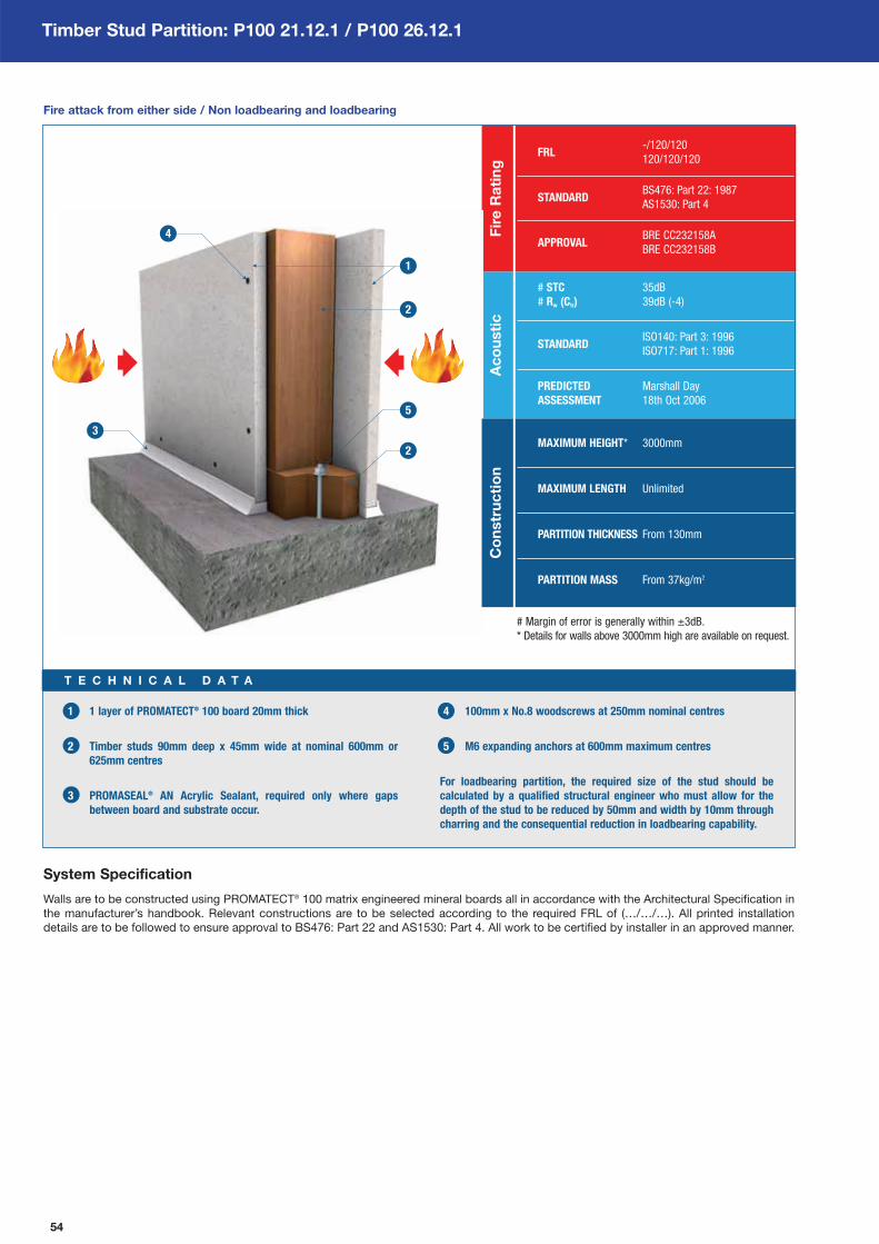
54
Timber Stud Partition: P100 21.12.1 / P100 26.12.1
FRL-/120/120
120/120/120
STANDARDBS476: Part 22: 1987
AS1530: Part 4
APPROVALBRE CC232158A
BRE CC232158B
Fir
e R
ati
ng
# STC 35dB
# Rw (Ctr) 39dB (-4)
STANDARDISO140: Part 3: 1996
ISO717: Part 1: 1996
PREDICTED Marshall Day
ASSESSMENT 18th Oct 2006
Ac
ou
sti
c
1 1 layer of PROMATECT® 100 board 20mm thick
2 Timber studs 90mm deep x 45mm wide at nominal 600mm or
625mm centres
3 PROMASEAL® AN Acrylic Sealant, required only where gaps
between board and substrate occur.
4 100mm x No.8 woodscrews at 250mm nominal centres
5 M6 expanding anchors at 600mm maximum centres
For loadbearing partition, the required size of the stud should be
calculated by a qualified structural engineer who must allow for the
depth of the stud to be reduced by 50mm and width by 10mm through
charring and the consequential reduction in loadbearing capability.
T E C H N I C A L D A T A
System Specification
Walls are to be constructed using PROMATECT® 100 matrix engineered mineral boards all in accordance with the Architectural Specification in
the manufacturer’s handbook. Relevant constructions are to be selected according to the required FRL of (…/…/…). All printed installation
details are to be followed to ensure approval to BS476: Part 22 and AS1530: Part 4. All work to be certified by installer in an approved manner.
Fire attack from either side / Non loadbearing and loadbearing
MAXIMUM HEIGHT* 3000mm
MAXIMUM LENGTH Unlimited
PARTITION THICKNESS From 130mm
PARTITION MASS From 37kg/m2
Co
nstr
uc
tio
n
# Margin of error is generally within ±3dB.
* Details for walls above 3000mm high are available on request.
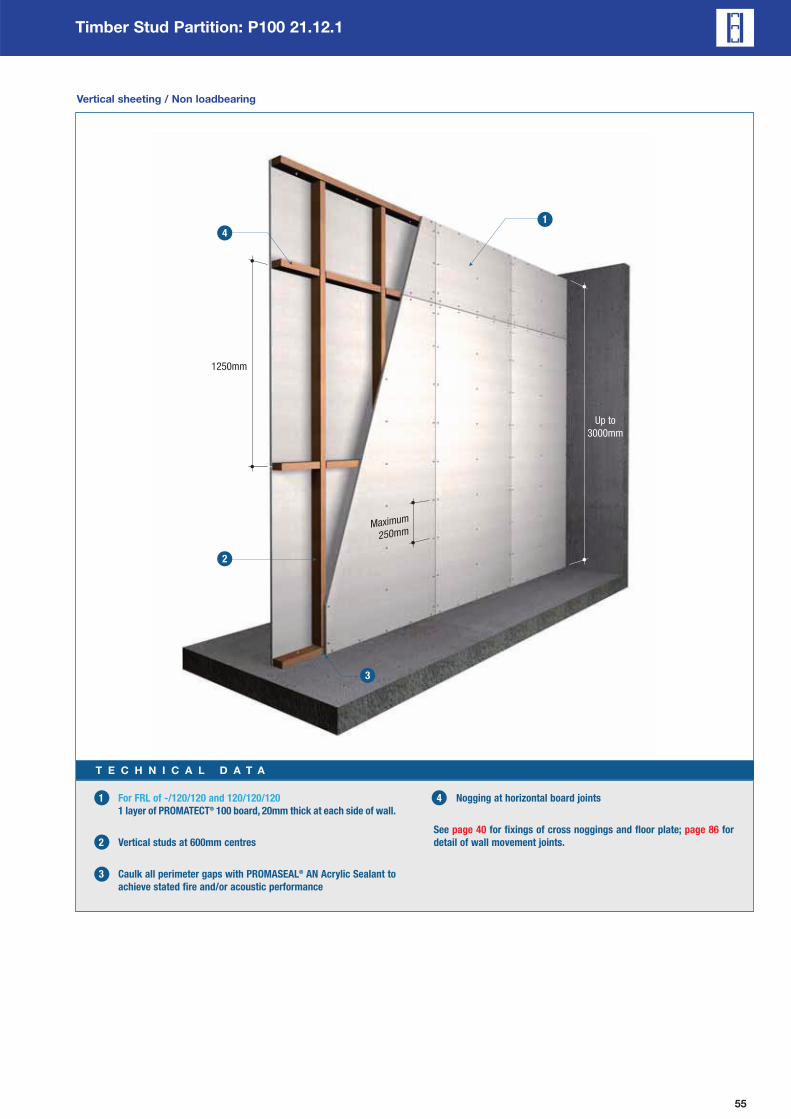
55
Timber Stud Partition: P100 21.12.1
Maximum
250mm
Up to
3000mm
1250mm
Vertical sheeting / Non loadbearing
1 For FRL of -/120/120 and 120/120/120
1 layer of PROMATECT® 100 board, 20mm thick at each side of wall.
2 Vertical studs at 600mm centres
3 Caulk all perimeter gaps with PROMASEAL® AN Acrylic Sealant to
achieve stated fire and/or acoustic performance
4 Nogging at horizontal board joints
See page 40 for fixings of cross noggings and floor plate; page 86 for
detail of wall movement joints.
T E C H N I C A L D A T A

56
Timber Stud Partition: P100 26.12.1
Maximum
250mm600mm
3000mm
Horizontal sheeting with nogging joint / Loadbearing
1 For FRL of -/120/120 and 120/120/120
1 layer of PROMATECT® 100 board, 20mm thick at each side of wall.
2 Vertical studs at 625mm centres
3 Caulk all perimeter gaps with PROMASEAL® AN Acrylic Sealant to
achieve stated fire and/or acoustic performance
4 Horizontal nogging at 600 centres
See page 40 for fixings of cross noggings and floor plate; page 86 for
detail of wall movement joints.
T E C H N I C A L D A T A

57
Timber Stud Partition: P100 21.12.1 / P100 26.12.1
Architectural Specification
The following are standard Architectural Specifications for internal partition systems using PROMATECT® 100. The designer must determine the
suitability of the design to the application and requirements before undertaking or constructing any works relating to the specifications and
where in doubt should obtain the advice of a suitably qualified engineer.
Fire Attack From Either Side / NON LOADBEARING & LOADBEARING
120 minutes of fire rating, integrity and insulation in accordance with the criteria of BS476: Part 22: 1987 and AS1530: Part 4.
Acoustic Performance
The partition system shall have a Weighted Sound Reduction Index of Rw 39.
Supporting Structure
Care should be taken that any structural element by which the partition system is supported, e.g. steel stud or perimeter steel channel, has
fire resistance of at least 120 minutes.
Lining Boards
Single layer each side 20mm PROMATECT® 100 matrix engineered mineral boards as manufactured by Promat International (Asia Pacific)
Ltd. All joints to be coincident with framing. Standard board dimensions 1200mm x 2500mm x 20mm.
Fixing
Softwood timber, 90mm deep x 45mm wide will be fixed to the perimeter of the opening where the partition system is to be installed using
M6 expanding anchors at 600mm maximum centres.
Where the boards are to be installed with their long edges vertical, the studs are located at 600mm maximum centres with cross noggings
at 1250mm centres. Where the boards are to be installed with their long edges horizontal, the studs are located at 625mm centres with
cross noggings at 600mm centres.
The PROMATECT® 100 boards are fixed to the framework using 100mm x No.8 woodscrews at maximum 250mm centres, a minimum of
12mm from the board edge.
Where there is a requirement for loadbearing, the required size of the timber stud will be calculated by a qualified structural
engineer who should allow for the depth of the stud to be reduced by 50mm and the width by 10mm through charring.
Tests & Standards
Along with all material tests the complete system along with the framing is tested in accordance with the criteria of BS476: Part 22 and
AS1530: Part 4.
Jointing
Plain butt joints between machined edges of boards. (1)
Joints filled in preparation for painting. (2)
Joints filled and taped in preparation for decoration. (3)
Follow-on Trades
Surface of boards to be prepared for painting/plastering/tiling(4) in accordance with manufacturer’s recommendations.
NOTES:
• (1), (2), (3), (4) delete as appropriate.
• Perimeter gaps will be filled with fire resistant PROMASEAL® AN Acrylic Sealant.
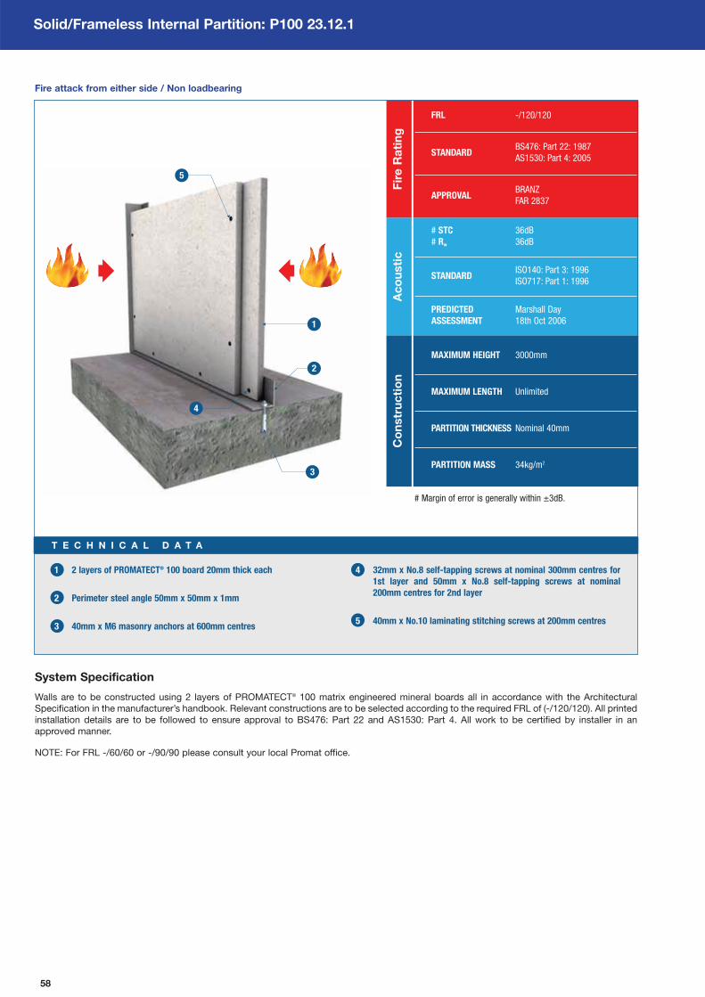
58
Solid/Frameless Internal Partition: P100 23.12.1
FRL -/120/120
STANDARDBS476: Part 22: 1987
AS1530: Part 4: 2005
APPROVALBRANZ
FAR 2837
Fir
e R
ati
ng
# STC 36dB
# Rw 36dB
STANDARDISO140: Part 3: 1996
ISO717: Part 1: 1996
PREDICTED Marshall Day
ASSESSMENT 18th Oct 2006
Ac
ou
sti
c
1 2 layers of PROMATECT® 100 board 20mm thick each
2 Perimeter steel angle 50mm x 50mm x 1mm
3 40mm x M6 masonry anchors at 600mm centres
4 32mm x No.8 self-tapping screws at nominal 300mm centres for
1st layer and 50mm x No.8 self-tapping screws at nominal
200mm centres for 2nd layer
5 40mm x No.10 laminating stitching screws at 200mm centres
T E C H N I C A L D A T A
System Specification
Walls are to be constructed using 2 layers of PROMATECT® 100 matrix engineered mineral boards all in accordance with the Architectural
Specification in the manufacturer’s handbook. Relevant constructions are to be selected according to the required FRL of (-/120/120). All printed
installation details are to be followed to ensure approval to BS476: Part 22 and AS1530: Part 4. All work to be certified by installer in an
approved manner.
NOTE: For FRL -/60/60 or -/90/90 please consult your local Promat office.
Fire attack from either side / Non loadbearing
Co
nstr
uc
tio
n
# Margin of error is generally within ±3dB.
MAXIMUM HEIGHT 3000mm
MAXIMUM LENGTH Unlimited
PARTITION THICKNESS Nominal 40mm
PARTITION MASS 34kg/m2

59
Solid/Frameless Internal Partition: P100 23.12.1
Maximum
200mm
Up to
3000mm
Two layer / Non loadbearing
1 For FRL of -/120/120
2 layers of PROMATECT® 100 board, 20mm thick at each side of wall.
2 Steel perimeter angle 50mm x 50mm x 1mm
3 40mm x M6 masonry anchors at 600mm centres
4 32mm x No.8 self-tapping screws at nominal 300mm centres for
1st layer and 50mm x No.8 self-tapping screws at nominal
200mm centres for 2nd layer. Both layers fixed to perimeter angle.
5 40mm x No.10 laminating stitching screws at
nominal 200mm centres
See page 89 for wall connection details.
T E C H N I C A L D A T A

Solid/Frameless Internal Partition: P100 23.12.1
Architectural Specification
The following are standard Architectural Specifications for internal partition systems using PROMATECT® 100. The designer must determine the
suitability of the design to the application and requirements before undertaking or constructing any works relating to the specifications and
where in doubt should obtain the advice of a suitably qualified engineer.
Fire Attack From Either Side / NON LOADBEARING
120 minutes of fire rating, integrity and insulation in accordance with the criteria of BS476: Part 22: 1987 and AS1530: Part 4.
Acoustic Performance
The partition system shall have a Weighted Sound Reduction Index of Rw 36.
Supporting Structure
Care should be taken that any structural element by which the partition system is supported, e.g. steel stud or perimeter steel channel, has
fire resistance of at least 120 minutes.
Lining Boards
Two layers x 20mm PROMATECT® 100 matrix engineered mineral boards as manufactured by Promat International (Asia Pacific) Ltd.
Stagger joints by at least 300mm. Standard board dimensions 1200mm x 2500mm x 20mm.
Fixing
Galvanised steel frame made of perimeter steel angle 50mm x 50mm x 1mm thick will be fastened to the wall/floor/ceiling with 40mm x M6
masonry anchors at nominal 500mm centres.
First layer of 20mm thick PROMATECT® 100 boards will be fixed to the perimeter angle using 32mm x No.8 self-drilling or self-tapping
screws at 300mm centres. Second layer 20mm, fixed to the first layer using 40mm x No.10 laminating stitching screws at 300mm centres
down the centre of each panel at each board joint. Use 50mm x No.8 self-tapping screws at 200mm centres to fix second layer to the
perimeter angle.
Tests & Standards
The complete system along with material and framing is tested in accordance with the criteria of BS476: Part 22 and AS1530: Part 4.
Jointing
Plain butt joints between machined edges of boards. (1)
Joints filled in preparation for painting. (2)
Joints filled and taped in preparation for decoration. (3)
Follow-on Trades
Surface of boards to be prepared for painting/plastering/tiling(4) in accordance with manufacturer’s recommendations.
NOTES:
• (1), (2), (3), (4) delete as appropriate.
• Perimeter gaps will be filled with fire resistant PROMASEAL® AN Acrylic Sealant.
60
61
Chapter 4:
Ceilings & Floors
SystemsIndex of PROMATECT® 100 Ceilings & Floors Systems ____ 62
General Information _____________________________________ 64
Self-supporting Ceiling Membrane _______________________ 68
Timber Floor Protection _________________________________ 74
Mezzanine Floor ________________________________________ 79

62
Ceilings & Floors Systems Index
Type of System Total Tests and assessments
ceilings and floors codeFRL Mineral wool
thickness standards/labsPage no.
P100 14SL.12(1) -/120/120 Not required From 150mmAS1530: Part 4 Report no.
68• BRE CC232157B
P100 14SL.12(2) -/120/120 Not required From 150mmAS1530: Part 4 Report no.
70• BRE CC232157A
P100 14SL.12(3) -/120/120 Not required From 105mmAS1530: Part 4 Report no.
72• CSIRO FCO2515 & FAR2885
P100 11.60 60/60/60 Not required 267mmAS1530: Part 4 Report no.
74• BRANZ FAR2886
P100 11.90(1) 90/90/90 Not required 267mmBS476: Part 21 Report no.
75• LPC TE90019
Self-supporting ceiling membrane
(Solid type 1)
Self-supporting ceiling membrane
(Solid type 2)
Self-supporting ceiling membrane
(Solid type 3)
Timber floor protection (Type 2)
Timber floor protection (Type 1)
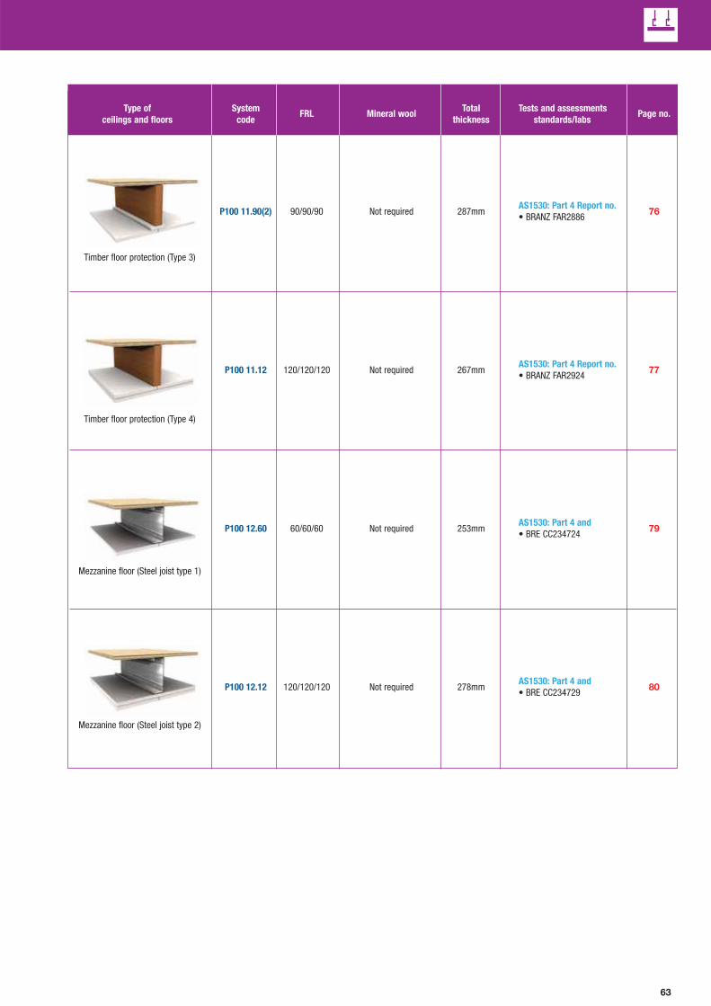
63
Type of System Total Tests and assessments
ceilings and floors codeFRL Mineral wool
thickness standards/labsPage no.
P100 11.90(2) 90/90/90 Not required 287mmAS1530: Part 4 Report no.
76• BRANZ FAR2886
P100 11.12 120/120/120 Not required 267mmAS1530: Part 4 Report no.
77• BRANZ FAR2924
P100 12.60 60/60/60 Not required 253mmAS1530: Part 4 and
79• BRE CC234724
P100 12.12 120/120/120 Not required 278mmAS1530: Part 4 and
80• BRE CC234729
Timber floor protection (Type 3)
Timber floor protection (Type 4)
Mezzanine floor (Steel joist type 1)
Mezzanine floor (Steel joist type 2)

64
Ceilings & Floors General Information
Introduction
Promat carries a wide range of fire rated ceiling and floor systems
with fire resistance of up to 240 minutes. Generally, PROMATECT®
ceiling and floor systems provide horizontal fire barriers to prevent
vertical spread of fire.
PROMATECT® ceiling and floor systems have been extensively
tested and assessed to provide resistance to fire from above, below
or above and below. They satisfy the integrity and insulation criteria
of BS476: Parts 20, 21, 22 and 23: 1987 and/or AS 1530 Part 4. The
flooring systems not only meet the integrity and insulation criteria
but also meet the loadbearing capacity (structural adequacy) criteria
of British and Australian national standards.
The system design depends on performance requirements but in
overall terms, PROMATECT® ceiling and floor systems can be
divided into the following categories.
1. Self-supporting Membrane Ceilings
These are normally non-loadbearing and, depending on the type of
construction, are used to provide protection from fire attack from
below and/or above. Ceiling panels are fixed into a steel or timber
framing system spanning and supported between two walls.
Self-supporting membrane ceilings should normally be tested or
assessed in accordance with BS476: Part 22 and/or AS1530:
Part 4 to satisfy the failure criteria of integrity and insulation.
These ceiling systems allow for the protection to or from services
contained within the ceiling void. They will also provide protection
to steel beams that are required to meet the criteria of BS476:
Part 23 where exposure to fire is from below.
2. Suspended Membrane Ceilings
These are normally non-loadbearing and are used to provide
protection from fire attack from below. The ceilings generally
incorporate steel grid systems suspended from a structure.
Suspended membrane ceilings should normally be tested or
assessed in accordance with BS476: Part 22 and/or AS1530:
Part 4 to satisfy the failure criteria of integrity and insulation.
These ceiling systems allow for the protection to or from services
contained within the ceiling void. They will also provide protection
to steel beams that are required to meet the criteria of BS476:
Part 23 where exposure to fire is from below.
3. Loadbearing Floor Systems
The flooring can be of timber or chipboard floorboards supported
by either timber joists or steel joists system. PROMATECT® boards
can be directly fixed onto these joists or fixed to a suspended
exposed or concealed metal grid system.
This type of ceiling should normally be tested or assessed in
accordance with BS476: Part 21 and/or AS1530: Part 4 and is
required to satisfy the three failure criteria of loadbearing capacity
(structural adequacy), integrity and insulation.
4. Suspended Ceiling Protection To Steel Beams
This type of ceiling is used mainly for protection of steel beams
supporting a loadbearing concrete floor slab and should be tested
or assessed to BS476: Part 23 and AS1530: Part 4. PROMATECT®
boards are fixed to a metal exposed or concealed grid system
suspended from the structure above.
Advantages
PROMATECT® ceiling and floor systems require less material to
achieve similar fire resistant levels when compared to the industry
average. This can lead to more simplified construction methods
than the standard equivalent. Use of PROMATECT® therefore helps
to increase productivity and reduce overall installation costs.
PROMATECT® ceiling and floor systems have been developed by
Promat International to satisfy standard requirements for internal
applications. Benefits include:
Time & Cost Effectiveness
Simple construction methods reduce installation cost and time
compared to traditional systems.
Lightweight
Lighter loads on structures compared to industry average systems
for equivalent fire rating.
Thermal Resistance
Excellent thermal resistance performance.
Design Flexibility
Lighter weight allows increased ceiling span, reduced support
structure sizes and/or reduced system thickness.
Acoustic Performance
Tested and assessed to ISO140-3 1995 and ISO717-1 1996 to meet
the needs of the industry. Please refer to pages 41 and 42 for details.
Board Fixing
Longitudinal board joints must coincide with framing members.
If the boards are in one layer, the transverse joints must be
backed with fillet strips made of PROMATECT® boards or timber
noggings for traditional timber joist construction. For boards
laminated in two layers, the joints must be staggered by at
least 500mm.
PROMATECT® boards may be fixed to the steel members using
No.8 “Bugle” head self-drilling and self-tapping screws. No.8
woodscrews shall be used to fix boards to timber frame. For boards
laminated in two layers, the outer layer boards may be stitched to
the preceding layer with No.10 laminating screws.
Minimum edge distance to fasteners and the maximum spacing
between screws must be maintained. Please refer to system detail
for screw spacing requirements.

65
Ceilings & Floors General Information
General Design Considerations
The following are some of the factors which should be considered
when determining the correct specification to ensure a ceiling or a
floor system provides the required design performance under both
fire and ambient conditions. Further advice is readily available from
a local Promat office.
1. Supporting Structure Design
The design of the framing system should be adequate for the
design loads of the ceiling and floor. PROMATECT® systems have
been designed for timber or steel framing as described in the
system specification.
For timber framing system used in loadbearing floor application, it
must be designed in accordance with BS5268, AS1720.1 and/or
AS1684. The width, the depth and the spacing of the joists have to
be carefully specified to ensure that the timber floor will serve its
intended fire performance.
For steel framed ceiling systems, it is critical to adhere to the
dimension of the steel sections, the grid spacing, the suspension
members (if any) and the fastening methods employed. Framing
members could change depending on the factors such as ceiling
span, movement and deflection and local regulations.
Larger or more frequent frame sections can often improve the
fire and structural performance. The framing for the ceiling
systems must be securely fixed back to a substrate that has an
equal or greater fire performance than the ceiling. All fixings must
be non-combustible and must be similar to those listed in the
approval documents.
2. Non Loadbearing Ceilings
Non loadbearing PROMATECT® ceiling systems can be generally
divided into steel frame suspended ceiling and self-supporting
membrane ceiling. The steel framing as noted in the system
specification is appropriate for the given span. Larger dimension of
steel sections or more frequent spacing will be required for a ceiling
span larger than specified.
At wall connections, mechanical joints are required and these joints
must be carefully designed so that they accommodate the required
expansion of steel at elevated temperature.
Non-loadbearing ceilings in this handbook are not trafficable.
Trafficable ceilings for maintenance purposes can be designed.
Further advice on such designs can be obtained from the Promat
Technical Department.
3. Loadbearing Ceilings
There are two types of PROMATECT® loadbearing floor systems
available. One is comprised of timber joists while the other is of
steel joists. Flooring material, timber type, thickness and jointing are
all critical. Timber framing shall be of solid timber and must be
designed in accordance with BS5268, AS1720.1 and/or AS1684
whereas for steel framing, the members should be designed in
accordance with BS5950 and/or AS4600.
4. Acoustics
Ceiling and floor systems have been developed to also meet
specific acoustic requirements. These include ratings for sound
transmission, sound impact and sound absorption. Please refer to
pages 41 and 42 for further information.
5. Movement Joint
Movement stress from dimensional changes due to varying
temperature or moisture conditions can cause cracking and
other symptoms of distress in ceiling linings.
Other external forces such as impact or vibration can directly affect
structural movement of ceilings. This movement can be controlled
through a variety of design techniques such as introducing
perimeter relief and slip connections to reduce the transfer of stress
from the structure to other building sub-elements and/or through
the use of expansion joints, control joints and construction joints.
Expansion joints are needed when a ceiling abuts a rigid mass.
Where ceiling dimensions exceed 10m in either direction, a control
joint should be used, (see page 92). Control joints should also be
located to intersect column penetrations, light fixtures and air
diffusers. The introduction of a control joint into a fire-rated system
is essential when an opening for flame and temperature
transmission is created. This and similar openings have to be
properly treated with approved Promat fire-stopping material.
6. Caulking & Service Penetrations
To maintain the fire performance and, where applicable, the
acoustic performance of the ceiling system, perimeter and other
gaps must be appropriately filled with suitable caulking material.
PROMASEAL® AN Acrylic Sealant or other tested fire and acoustic
rated material of equivalent or better performance must be used.
Care needs to be taken in detailing a suitable fire-stopping system
around any penetration of the ceiling by services to ensure:
a) the fire-stopping material remains in situ,
b) fire and smoke do not penetrate the floor cavity
which ultimately will lead to,
c) premature collapse of the joists and/or penetration of
fire and smoke through the timber flooring.
Allowance should be made for thermal movement of the services in
both ambient and fire conditions to ensure loads are not applied to
the ceiling assembly. Some examples of service penetrations
include those penetrations by electrical cables, conduits or wires,
plastic and metal pipes, air-conditioning and ventilation ductwork.
Further guidance on the sealing of service penetrations can be
obtained from pages 93 and 94 of this handbook.
7. Light Fittings
Light fittings located within a ceiling cavity should normally be
enclosed in an adequately supported fire protection box to prevent
fire spreading rapidly into the ceiling cavity. Most light fittings will
require ventilation in normal use and this consideration should
certainly be factored into light box design. Please consult Promat
for details.
8. Access Panels & Hatches
Where access into a ceiling void is required, panels and hatches will
need to be installed. Please refer to page 95 or consult Promat
Technical Department for details.
Conclusion
Most building regulations stipulate limitations on the use of fire
protecting suspended ceilings in certain situations. Care should be
therefore taken that the use of a suspended ceiling system is
acceptable to the approval authorities.

66
Ceilings & Floors General Information
Steel Frame Components
Components Selection
In order to maintain the fire and acoustic performance of
PROMATECT® ceiling systems, the type of profile used for
framing is important. Construction of the PROMATECT® fire rated
steel framed ceilings can be achieved using standard steel section
components. Steel framing may be C or ‘I’ sections, furring
channels, top hats, trusses or similar members which in all cases
should be designed in accordance with BS5950, AS4600 and/or
equivalent standard.
The profiles described in the system specification should be
adhered to at all times. However, the profiles may be amended
as long as they possess comparable performances to the
specified profiles.
Perimeter Tracks & Steel Joists
For Self-supporting Ceilings
This system is the most appropriate especially in situations where it
is difficult to install a suspended ceiling and/or within narrow rooms
or corridors. No hangers are required for this system, producing
shorter installation times and provision of a completely free cavity
for the accommodation of ductwork and services.
For Australia, suitable framing profiles can be obtained from
Rondo Building Services who provide comprehensive
documentation for ceiling framing systems.
The framing system generally consists of a perimeter track profile
and steel joists. During the design stage, choosing the right depth
of the profile takes into account the maximum allowable span. The
main function of the perimeter tracks is to provide friction joints that
hold the joists in position until the PROMATECT® board is fitted.
They also provide allowance for movement of building structure
under ambient conditions. Under fire conditions these tracks allow
for the steel joists to expand to minimise deflection of the ceiling
construction that may cause excessive cracking and then
delamination of the lining boards. This type of joint is suitable for
ceiling membrane systems of up to 3000mm span. Track sections
should be fixed to the supporting structure using suitable masonry
anchors at maximum 500mm intervals. Fixings should be located
not more than 100mm from either end of the track section.
For membrane ceilings with a span of more than 3000mm,
mounting brackets are required at both ends of the steel joists. The
mounting brackets will be attached to the wall, at the same time,
and shall be designed to allow for expansion of the steel joists.
See pages 90 and 91 for further details.
1 Wall U-profile
2 Horizontal C-profile
3 Fixing point
Fixing of primary and secondary profiles
500mm
Maximum 62
5mm
500mm

67
Ceilings & Floors General Information
Detail 1
Detail 2
Detail 3
1200mm
1200mm
625mm
625mm
625mm
625mm
Steel Frame Components
Steel Framing System For Suspended Ceiling
This system is the most appropriate for the installation of large
area suspended ceilings. The steel structure of the suspended
ceiling is composed of a grid of C-profiles and accessories, made
of galvanised steel. The standard length of the C-profile is either 3m
or 6m.
1 Primary profile 5 Hanger
2 Secondary profile 6 Hanger wire
3 Fixing hooks 7 Promat board
4 Connector
NOTE: For details of framing requirements for
the installation of access panels and hatches,
please refer to page 95.
Typical Profiles For Ceiling Construction
Detail 1 Detail 2
Type : C-60 profile
Dimension : 60mm x 27mm
Application : Primary profile,
secondary profile or
cross profile.
Type : Cross fixer
Dimension : 27mm x 55mm x
25mm (0.8mm)
Application : Fix cross profile to
secondry profile.
Type : Connector
Dimension : 27mm x 61.5mm x
100mm (0.8mm)
Application : To link two C-60
profiles.
Type : Fixing hooks
Dimension : 50mm x 58mm x
0.8mm
Application : Fix secondary profile
to primary profile.
Type : Hangers or wire
Ø 6mm
Dimension : 90mm x 58mm x
1.5mm
Application : Fix primary profile
to ceiling.
Detail 3 and
optional hanger types

68
Self-supporting Ceiling Membrane: P100 14SL.12 (1)
FRL -/120/120
STANDARD AS1530: Part 4
APPROVAL BRE: CC 232157BFir
e R
ati
ng
# STC 36dB
# Rw 36dB
STANDARDISO140: Part 3: 1996
ISO717: Part 1: 1996
PREDICTED Marshall Day
ASSESSMENT 16th Aug 2007
Ac
ou
sti
c# Margin of error is generally within ±3dB.
Solid type 1 – Fire attack from above / Non loadbearing
Maximum 3000mm
600mm
Nominal250mm
Nominal250mm
Overlapminimum 600mm
1 2 layers of PROMATECT® 100 board 20mm thick each
2 All longitudinal board joints must be coincident with the steel
framework, longitudinal board joints between the 2 layers must be
staggered by 600mm.
3 Gap at perimeter to be caulked with
PROMASEAL® AN Acrylic Sealant
4 1 layer of PROMATECT® 100 cover strip 85mm x 20mm thick
5 1 layer of PROMATECT® 100 cover strip 50mm x 20mm thick at
transverse joints in the 1st layer
6 Steel joist at 600mm centres
7 No. 8 steel screws at nominal 250mm centres
• 32mm long to secure cover strips to steel
• 50mm long to secure 1st layer board to steel
• 72mm long to secure 2nd layer board to steel
• 35mm long laminating screws to stitch transverse joints in 2nd
layer board to 1st layer board
8 Steel wall channel fixed to substrate at nominal 500mm centres
Please refer to pages 90 to 92 for perimeter details and control joints.
T E C H N I C A L D A T A
System Specification
Ceilings are to be constructed using 2 layers of 20mm thick PROMATECT® 100 matrix engineered mineral boards all in accordance with the
Architectural Specification in the manufacturer’s handbook. Relevant constructions are to be selected according to the required FRL of
-/120/120 (fire from above) of the selected elements. All printed installation details are to be followed to ensure approval to AS1530: Part 4.
All work to be certified by installer in an approved manner.
MAXIMUM SPAN 3000mm
NOTE: For spans greater than
3000mm, please consult Promat.
CEILING THICKNESS From 150mm
CEILING MASS From 39kg/m2Co
nstr
uc
tio
n

Maximum
span
Minimum
sectional
modulus
Steel joist section Wall channel
Expansion at
each end of
steel joist
5.0m 34800mm32 back-to-back lipped C
102mm x 51mm x 18mm x 2.5mm
100mm long L
125mm x 125mm x 3.0mm30mm
6.0m 46800mm32 back-to-back lipped C
127mm x 51mm x 18mm x 2.5mm
100mm long L
125mm x 125mm x 3.0mm36mm
7.4m 70100mm3 Lipped C-203mm x 76mm x 34mm x 3.0mm200mm long L
125mm x 125mm x 3.0mm45mm
8.3m 91600mm3 Lipped C-250mm x 75mm x 20mm x 3.0mm240mm long L
125mm x 125mm x 3.0mm50mm
9.0m 124360mm32 back-to-back lipped C
225mm x 75mm x 20mm x 2.3mm
200mm long L
125mm x 125mm x 3.0mm55mm
10.0m 183200mm32 back-to-back lipped C
250mm x 75mm x 20mm x 30mm
240mm long L
125mm x 125mm x 3.0mm60mm
69
Self-supporting Ceiling Membrane: P100 14SL.12 (1)
Architectural Specification
The following are standard architectural specifications for ceiling systems using PROMATECT® 100. The designer must determine the suitability
of the design to the application and requirements before undertaking or constructing any works relating to the specifications and where in doubt
should obtain the advice of a suitably qualified engineer.
Fire Attack From Above / NON LOADBEARING120 minutes fire rating, integrity and insulation in accordance with the criteria of AS1530: Part 4. Non loadbearing.
Supporting StructureCare should be taken that any structural element by which the ceiling system is supported, e.g. steel stud, perimeter steel channel, has fire
resistance of at least 120 minutes and is capable of supporting the ceiling membrane system for the required period.
Lining BoardsTwo layers of 20mm PROMATECT® 100 matrix engineered mineral boards as manufactured by Promat International (Asia Pacific) Ltd. All
joints to coincide with steel framing. Standard board dimensions 1200mm x 2500mm x 20mm.
FixingWall tracks are anchored to the wall using 60mm x M6 steel expanding anchors at maximum 500mm centres. Ceiling joists comprising steel
lipped channels are then positioned at 600mm maximum centres. The ends of each of the steel joists are friction fitted between the flanges
of the steel perimeter channels. Wall tracks and ceiling joists section sizes are to be selected as appropriate according to the ceiling span
according to the steel joist table below.
Steel Joist Table
Ceiling span Proposed steel joist Proposed wall tracks
Up to 1.5m Lipped C-92 x 35mm x 5mm x 0.55mm C-94 x 32mm x 0.55mm
Up to 2.0m Lipped C-92 x 35mm x 5mm x 1.15mm C-94 x 32mm x 0.55mm
Up to 2.5m Lipped C-102 x 51mm x 12.5mm x 1.2mm C-100 x 40mm x 0.6mm
Up to 3.0m Lipped C-102 x 51mm x 12.5mm x 1.5mm C-100 x 40mm x 0.6mm
Steel Sections Table ( For spans up to 10m)
The topside of the steel joists and the perimeter channels are covered with 20mm thick PROMATECT® 100 fillets, minimum width 50mm for
the perimeter channels and 85mm for the steel joists. The fillets are fixed in position using minimum 32mm x No.8 screws at 250mm centres.
A layer of 20mm thick PROMATECT® 100 boards is then fixed to the topside of the steel framework and fillets using minimum 50mm x No.8
screws at maximum 250mm centres. All longitudinal board joints must be coincident with the steel framework. Transverse joints in the
boards are backed with PROMATECT® 100 cover strips, 20mm thick x 50mm wide. The second layer is fixed in a similar manner using
minimum 72mm x No.8 screws, ensuring that all joints in the two layers are staggered by 600mm.
Tests & StandardsThe complete system along with material and framing is tested and assessed in accordance with the criteria of AS1530: Part 4.
JointingPlain butt joints between machined edges of boards. (1)
Joints filled in preparation for painting. (2)
Joints filled and taped in preparation for decoration. (3)
Follow-on TradesSurface of boards to be prepared for painting/plastering/tiling(4) in accordance with manufacturer’s recommendations.
NOTES:
• (1), (2), (3), (4) delete as appropriate.
• The above ceiling is approved for spans up to 3000mm using framing members as detailed.
• Perimeter gaps will be filled with fire resistant PROMASEAL® AN Acrylic Sealant.

70
Self-supporting Ceiling Membrane: P100 14SL.12 (2)
FRL -/120/120
STANDARD AS1530: Part 4
APPROVAL BRE: CC 232157AFir
e R
ati
ng
# STC 36dB
# Rw 36dB
STANDARDISO140: Part 3: 1996
ISO717: Part 1: 1996
PREDICTED Marshall Day
ASSESSMENT 16th Aug 2007
Ac
ou
sti
c# Margin of error is generally within ±3dB.
Solid type 2 – Fire attack from below / Non loadbearing
Maximum 3000mm
600mm
Nominal
250mm
Nominal
250mm
Overlap
minimum 600mm
1 2 layers of PROMATECT® 100 board 20mm thick each
2 All longitudinal board joints must be coincident with the steel
framework, longitudinal board joints between the 2 layers must be
staggered by 600mm
3 Gap at perimeter to be caulked with
PROMASEAL® AN Acrylic Sealant
4 1 layer of PROMATECT® 100 cover strip 85mm x 20mm thick
5 1 layer of PROMATECT® 100 cover strip 50mm x 20mm thick at
transverse joints in the 1st layer
6 Steel joist at 600mm centres
7 No. 8 steel screws at nominal 250mm centres
• 32mm long to secure cover strips to steel
• 50mm long to secure 1st layer board to steel
• 72mm long to secure 2nd layer board to steel
• 35mm long laminating screws to stitch transverse joints in 2nd
layer board to 1st layer board
8 Steel wall channel
Please refer to pages 90 to 92 for perimeter details and control joints.
T E C H N I C A L D A T A
System Specification
Ceilings are to be constructed using 2 layers of 20mm thick PROMATECT® 100 matrix engineered mineral boards all in accordance with the
Architectural Specification in the manufacturer’s handbook. Relevant constructions are to be selected according to the required FRL of
-/120/120 (fire from below) of the selected elements. All printed installation details are to be followed to ensure approval to AS1530: Part 4.
All work to be certified by installer in an approved manner.
MAXIMUM SPAN 3000mm
NOTE: For spans greater than
3000mm, please consult Promat.
CEILING THICKNESS From 150mm
CEILING MASS From 39kg/m2Co
nstr
uc
tio
n
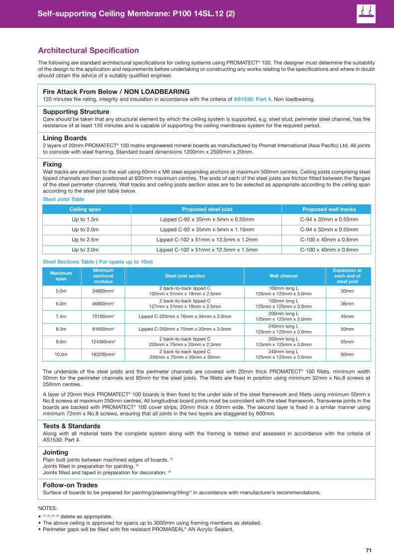
71
Self-supporting Ceiling Membrane: P100 14SL.12 (2)
Architectural Specification
The following are standard architectural specifications for ceiling systems using PROMATECT® 100. The designer must determine the suitability
of the design to the application and requirements before undertaking or constructing any works relating to the specifications and where in doubt
should obtain the advice of a suitably qualified engineer.
Fire Attack From Below / NON LOADBEARING120 minutes fire rating, integrity and insulation in accordance with the criteria of AS1530: Part 4. Non loadbearing.
Supporting StructureCare should be taken that any structural element by which the ceiling system is supported, e.g. steel stud, perimeter steel channel, has fire
resistance of at least 120 minutes and is capable of supporting the ceiling membrane system for the required period.
Lining Boards2 layers of 20mm PROMATECT® 100 matrix engineered mineral boards as manufactured by Promat International (Asia Pacific) Ltd. All joints
to coincide with steel framing. Standard board dimensions 1200mm x 2500mm x 20mm.
FixingWall tracks are anchored to the wall using 60mm x M6 steel expanding anchors at maximum 500mm centres. Ceiling joists comprising steel
lipped channels are then positioned at 600mm maximum centres. The ends of each of the steel joists are friction fitted between the flanges
of the steel perimeter channels. Wall tracks and ceiling joists section sizes are to be selected as appropriate according to the ceiling span
according to the steel joist table below.
Steel Joist Table
Ceiling span Proposed steel joist Proposed wall tracks
Up to 1.5m Lipped C-92 x 35mm x 5mm x 0.55mm C-94 x 32mm x 0.55mm
Up to 2.0m Lipped C-92 x 35mm x 5mm x 1.15mm C-94 x 32mm x 0.55mm
Up to 2.5m Lipped C-102 x 51mm x 12.5mm x 1.2mm C-100 x 40mm x 0.6mm
Up to 3.0m Lipped C-102 x 51mm x 12.5mm x 1.5mm C-100 x 40mm x 0.6mm
Steel Sections Table ( For spans up to 10m)
The underside of the steel joists and the perimeter channels are covered with 20mm thick PROMATECT® 100 fillets, minimum width
50mm for the perimeter channels and 85mm for the steel joists. The fillets are fixed in position using minimum 32mm x No.8 screws at
250mm centres.
A layer of 20mm thick PROMATECT® 100 boards is then fixed to the under side of the steel framework and fillets using minimum 50mm x
No.8 screws at maximum 250mm centres. All longitudinal board joints must be coincident with the steel framework. Transverse joints in the
boards are backed with PROMATECT® 100 cover strips, 20mm thick x 50mm wide. The second layer is fixed in a similar manner using
minimum 72mm x No.8 screws, ensuring that all joints in the two layers are staggered by 600mm.
Tests & StandardsAlong with all material tests the complete system along with the framing is tested and assessed in accordance with the criteria of
AS1530: Part 4.
JointingPlain butt joints between machined edges of boards. (1)
Joints filled in preparation for painting. (2)
Joints filled and taped in preparation for decoration. (3)
Follow-on TradesSurface of boards to be prepared for painting/plastering/tiling(4) in accordance with manufacturer’s recommendations.
NOTES:
• (1), (2), (3), (4) delete as appropriate.
• The above ceiling is approved for spans up to 3000mm using framing members as detailed.
• Perimeter gaps will be filled with fire resistant PROMASEAL® AN Acrylic Sealant.
Maximum
span
Minimum
sectional
modulus
Steel joist section Wall channel
Expansion at
each end of
steel joist
5.0m 34800mm32 back-to-back lipped C
102mm x 51mm x 18mm x 2.5mm
100mm long L
125mm x 125mm x 3.0mm30mm
6.0m 46800mm32 back-to-back lipped C
127mm x 51mm x 18mm x 2.5mm
100mm long L
125mm x 125mm x 3.0mm36mm
7.4m 70100mm3 Lipped C-203mm x 76mm x 34mm x 3.0mm200mm long L
125mm x 125mm x 3.0mm45mm
8.3m 91600mm3 Lipped C-250mm x 75mm x 20mm x 3.0mm240mm long L
125mm x 125mm x 3.0mm50mm
9.0m 124360mm32 back-to-back lipped C
225mm x 75mm x 20mm x 2.3mm
200mm long L
125mm x 125mm x 3.0mm55mm
10.0m 183200mm32 back-to-back lipped C
250mm x 75mm x 20mm x 30mm
240mm long L
125mm x 125mm x 3.0mm60mm

72
Self-supporting Ceiling Membrane: P100 14SL.12 (3)
FRL -/120/120
STANDARD AS1530: Part 4
APPROVAL CSIRO FCO2515 & FAR 2885Fir
e R
ati
ng
# STC 39dB
# Rw 39dB
STANDARDISO140: Part 3: 1996
ISO717: Part 1: 1996
PREDICTED Marshall Day
ASSESSMENT 16th Aug 2007
Ac
ou
sti
c
MAXIMUM SPAN Please consult Promat
CEILING THICKNESS From 105mm
CEILING MASS From 38.8kg/m2
Co
nstr
uc
tio
n# Margin of error is generally within ±3dB.
Solid type 5 – Fire attack from above and below / Non loadbearing
Nominal
250mm
600mm
1 1 layers of PROMATECT® 100 board 20mm thick
2 Steel joists at 600mm nominal centres. For up to 2.5m span use
lipped channel 64mm x 38mm x 13mm x 2.5mm
3 Gap at perimeter to be caulked with
PROMASEAL® AN Acrylic Sealant
4 1 layer of PROMATECT® 100 cover strip 100mm x 20mm thick at
transverse joints in the top and bottom boards
5 35mm long screws
• No. 8 self tapping/drilling screws at 200mm centres to secure
board to steel
• No. 10 laminating screws at 100mm centres to stitch joints to
cover strips
6 Steel wall channel
Please refer to pages 90 to 92 for perimeter details and control joints.
T E C H N I C A L D A T A
System Specification
Ceilings are to be constructed using 20mm thick PROMATECT® 100 matrix engineered mineral boards all in accordance with the Architectural
Specification in the manufacturer’s handbook. Relevant constructions are to be selected according to the required FRL of -/120/120 (fire from
abpve and below) of the selected elements. All printed installation details are to be followed to ensure approval to AS1530: Part 4. All work to
be certified by installer in an approved manner.

73
Self-supporting Ceiling Membrane: P100 14SL.12 (3)
Architectural Specification
The following are standard architectural specifications for ceiling systems using PROMATECT® 100. The designer must determine the suitability
of the design to the application and requirements before undertaking or constructing any works relating to the specifications and where in doubt
should obtain the advice of a suitably qualified engineer.
Fire Attack From Below / NON LOADBEARING120 minutes fire rating, integrity and insulation in accordance with the criteria of AS1530: Part 4. Non loadbearing.
Supporting StructureCare should be taken that any structural element by which the ceiling system is supported, e.g. steel stud, perimeter steel channel, has fire
resistance of at least 120 minutes and is capable of supporting the ceiling membrane system for the required period.
Lining BoardsSingle layer each side of 20mm PROMATECT® 100 matrix engineered mineral boards as manufactured by Promat International (Asia Pacific)
Ltd. All joints to coincide with steel framing. Standard board dimensions 1200mm x 2500mm x 20mm.
FixingFor span up to 2.5m: At the perimeter of the ceiling, wall angles of 65mm x 50mm x 1.15mm thick will be bolted to the wall with M6 x
50mm long anchor bolts at 500mm nominal centres. The steel joists, made of lipped channels 64mm x 38mm x 13mm x 2.5mm, will then
be positioned at 600mm centres spanning across the width of the ceiling. The two ends of each of the steel joists will be simply rested on
the flanges of the angles. A minimum gap of 15mm shall be provided at both ends of the steel joists for expansion allowance.
A layer of 20mm thick PROMATECT®100 board is fixed on the topside and underside of the steel joists framework with 45mm long x No.8
self-tapping screws at maximum 200mm centres. Longitudinal joints between PROMATECT® 100 boards shall be coincident with the steel
joists. Transverse board joints, if any, shall be backed by 50mm wide x 20mm thick PROMATECT® 100 cover strips and secured with 35mm
long x No.10 laminating screws at 100mm maximumes.
Steel Sections Table ( for spans up to 4m)
*Special design wall channel for expansion between steel joist and wall channel.
Steel Sections Table ( for spans up to 10m)
Tests & StandardsAlong with all material tests the complete system along with the framing is tested and assessed in accordance with the criteria of
AS1530: Part 4.
JointingPlain butt joints between machined edges of boards. (1)
Joints filled in preparation for painting. (2)
Joints filled and taped in preparation for decoration. (3)
Follow-on TradesSurface of boards to be prepared for painting/plastering/tiling(4) in accordance with manufacturer’s recommendations.
NOTES:
• (1), (2), (3), (4) delete as appropriate.
• The above ceiling is approved for spans up to 3000mm using framing members as detailed.
• Perimeter gaps will be filled with fire resistant PROMASEAL® AN Acrylic Sealant.
Maximum
span
Minimum
sectional
modulus
Steel joist section Wall channel
Expansion at
each end of
steel joist
1.5m 2314mm3 C-65mm x 50mm x 0.6mm C-65mm x 50mm x 0.6mm 9mm
2.0m 4330mm3 C-65mm x 50mm x 1.15mm C-65mm x 50mm x 1.15mm 12mm
2.5m 7110mm3 Lipped C-65mm x 38mm x 13mm x 2.5mm C-65mm x 50mm x 1.15mm 15mm
3.0m 10300mm3 Lipped C-76mm x 44mm x 16mm x 2.5mm *C-81mm x 50mm x 2.5mm 18mm
3.5m 12840mm3 C-103mm x 34mm x 3.0mm *C-109mm x 50mm x 3.0mm 21mm
4.0m 17400mm3 Lipped C-102mm x 51mm x 18mm x 2.5mm *C-108mm x 50mm x 3.0mm 24mm
Maximum
span
Minimum
sectional
modulus
Steel joist section Wall channel
Expansion at
each end of
steel joist
5.0m 34800mm32 back-to-back lipped C
102mm x 51mm x 18mm x 2.5mm
100mm long L
125mm x 125mm x 3.0mm30mm
6.0m 46800mm32 back-to-back lipped C
127mm x 51mm x 18mm x 2.5mm
100mm long L
125mm x 125mm x 3.0mm36mm
7.4m 70100mm3 Lipped C-203mm x 76mm x 34mm x 3.0mm200mm long L
125mm x 125mm x 3.0mm45mm
8.3m 91600mm3 Lipped C-250mm x 75mm x 20mm x 3.0mm240mm long L
125mm x 125mm x 3.0mm50mm
9.0m 124360mm32 back-to-back lipped C
225mm x 75mm x 20mm x 2.3mm
200mm long L
125mm x 125mm x 3.0mm55mm
10.0m 183200mm32 back-to-back lipped C
250mm x 75mm x 20mm x 30mm
240mm long L
125mm x 125mm x 3.0mm60mm

74
Timber Floor Protection: P100 11.60
FRL 60/60/60
STANDARD AS 1530: Part 4
APPROVAL BRANZ FAR2886Fir
e R
ati
ng
# STC 36dB
# Rw 36dB
STANDARDISO140: Part 3: 1996
ISO717: Part 1: 1996
PREDICTED Marshall Day
ASSESSMENT 20th Aug 2007
Ac
ou
sti
c
# Margin of error is generally within ±3dB.
* Based on nominal weight of the board.
Fire attack from below / Loadbearing
Maximum 600mm
Nominal
200mm
Nominal
150mm
1 1 layer of PROMATECT® 100 board 20mm thick
2 Longitudinal board joints to coincide with timber joists
3 Gap at perimeter to be caulked with
PROMASEAL® AN Acrylic Sealant
4 Timber nogging 38mm x 38mm at 1250mm centres and to
coincide with transverse board joints
5 Timber joist minimum 225mm x 48mm at maximum 600 centres
6 Tongue-and-groove floorboards 22mm thick
7 50mm long galvanised clout nails or woodscrews at nominal
150mm centres
Please refer to pages 91 for perimeter detail.
T E C H N I C A L D A T A
System Specification
Timber floors are to be constructed using 20mm thick PROMATECT® 100 matrix engineered mineral boards all in accordance with the
Architectural Specification in the manufacturer’s handbook. Relevant constructions are to be selected according to the required FRL of 60/60/60
of the selected elements. All printed installation details are to be followed to ensure approval to as1530: Part 4. All work to be certified by
installer in an approved manner.
MAXIMUM SPAN As determined by structural
engineer based on timber type
and dimension
CEILING THICKNESS 267mm
CEILING MASS 43.3kg/m2Co
nstr
uc
tio
n
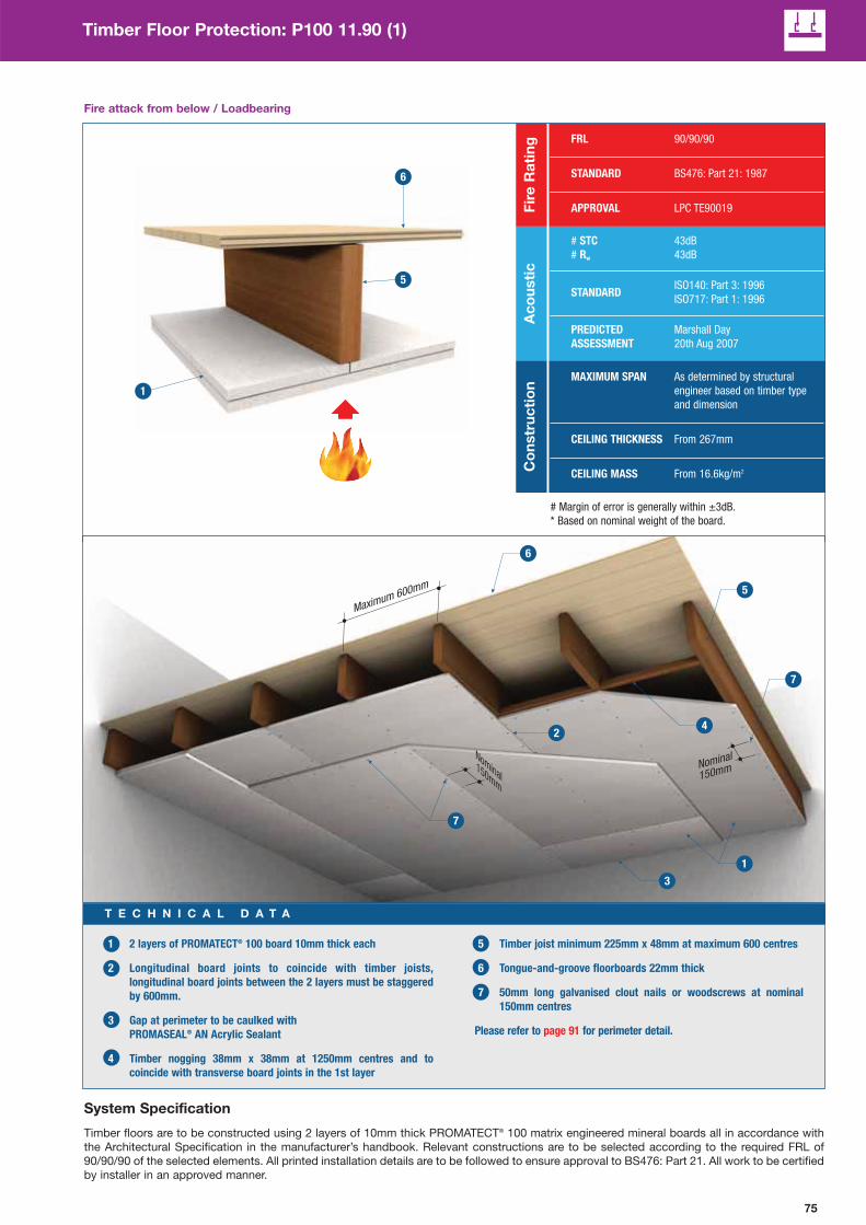
75
Timber Floor Protection: P100 11.90 (1)
FRL 90/90/90
STANDARD BS476: Part 21: 1987
APPROVAL LPC TE90019Fir
e R
ati
ng
# STC 43dB
# Rw 43dB
STANDARDISO140: Part 3: 1996
ISO717: Part 1: 1996
PREDICTED Marshall Day
ASSESSMENT 20th Aug 2007
Ac
ou
sti
c
# Margin of error is generally within ±3dB.
* Based on nominal weight of the board.
Fire attack from below / Loadbearing
Nominal
150mm
Maximum 600mm
Nominal
150mm
1 2 layers of PROMATECT® 100 board 10mm thick each
2 Longitudinal board joints to coincide with timber joists,
longitudinal board joints between the 2 layers must be staggered
by 600mm.
3 Gap at perimeter to be caulked with
PROMASEAL® AN Acrylic Sealant
4 Timber nogging 38mm x 38mm at 1250mm centres and to
coincide with transverse board joints in the 1st layer
5 Timber joist minimum 225mm x 48mm at maximum 600 centres
6 Tongue-and-groove floorboards 22mm thick
7 50mm long galvanised clout nails or woodscrews at nominal
150mm centres
Please refer to page 91 for perimeter detail.
T E C H N I C A L D A T A
System Specification
Timber floors are to be constructed using 2 layers of 10mm thick PROMATECT® 100 matrix engineered mineral boards all in accordance with
the Architectural Specification in the manufacturer’s handbook. Relevant constructions are to be selected according to the required FRL of
90/90/90 of the selected elements. All printed installation details are to be followed to ensure approval to BS476: Part 21. All work to be certified
by installer in an approved manner.
MAXIMUM SPAN As determined by structural
engineer based on timber type
and dimension
CEILING THICKNESS From 267mm
CEILING MASS From 16.6kg/m2Co
nstr
uc
tio
n

76
Timber Floor Protection: P100 11.90 (2)
FRL 90/90/90
STANDARD AS 1530: Part 4
APPROVAL BRANZ FAR2886Fir
e R
ati
ng
# STC 36dB
# Rw 36dB
STANDARDISO140: Part 3: 1996
ISO717: Part 1: 1996
PREDICTED Marshall Day
ASSESSMENT 20th Aug 2007
Ac
ou
sti
c
# Margin of error is generally within ±3dB.
* Based on nominal weight of the board.
Fire attack from below / Loadbearing
Maximum 600mm
Nominal
150mm
Nominal
150mm
1 1 layer of PROMATECT® 100 board 20mm thick
2 Longitudinal board joints to coincide with timber joists,
longitudinal board joints
3 Gap at perimeter to be caulked with
PROMASEAL® AN Acrylic Sealant
4 Timber joist minimum 225mm x 48mm at maximum 600 centres
5 1 layer of PROMATECT® 100 cover strip 100mm x 20mm thick
6 1 layer of PROMATECT® 100 cover strip 100mm x 20mm thick at
transverse joints
7 Galvanised clout nails or woodscrews at nominal 150mm centres
• 50mm long to fix cover strips to timber joists
• 75mm long to fix board to timber joists
8 Tongue-and-groove floorboards 22mm thick
Please refer to page 91 for perimeter detail.
T E C H N I C A L D A T A
System Specification
Timber floors are to be constructed using 20mm thick PROMATECT® 100 matrix engineered mineral boards all in accordance with the
Architectural Specification in the manufacturer’s handbook. Relevant constructions are to be selected according to the required FRL of 90/90/90
of the selected elements. All printed installation details are to be followed to ensure approval to AS1530: Part 4. All work to be certified by
installer in an approved manner.
MAXIMUM SPAN As determined by structural
engineer based on timber type
and dimension
CEILING THICKNESS From 287mm
CEILING MASS From 46.3kg/m2Co
nstr
uc
tio
n

77
Timber Floor Protection: P100 11.12
FRL 120/120/120
STANDARD AS1530: Part 4
APPROVAL LPC TE90019Fir
e R
ati
ng
# STC 39dB
# Rw 40dB
STANDARDISO140: Part 3: 1996
ISO717: Part 1: 1996
PREDICTED Marshall Day
ASSESSMENT 20th Aug 2007
Ac
ou
sti
c
# Margin of error is generally within ±3dB.
* Based on nominal weight of the board.
Fire attack from below / Loadbearing
Nominal
150mm
Maximum 600mm
Nominal
150mm
1 2 layers of PROMATECT® 100 board 20mm thick each
2 Longitudinal board joints to coincide with timber joists,
longitudinal board joints between the 2 layers must be staggered
by 600mm.
3 Gap at perimeter to be caulked with
PROMASEAL® AN Acrylic Sealant
4 Timber nogging 38mm x 38mm at 1250mm centres and to
coincide with transverse board joints in the 1st layer
5 Timber joist minimum 225mm x 48mm at maximum 600 centres
6 Tongue-and-groove floorboards 22mm thick
7 Galvanised clout nails or woodscrews at nominal 150mm centres
• 50mm long to fix cover strips to timber joists
• 75mm long to fix board to timber joists
Please refer to page 91 for perimeter detail.
T E C H N I C A L D A T A
System Specification
Timber floors are to be constructed using 2 layers of 20mm thick PROMATECT® 100 matrix engineered mineral boards all in accordance with
the Architectural Specification in the manufacturer’s handbook. Relevant constructions are to be selected according to the required FRL of
120/120/120 of the selected elements. All printed installation details are to be followed to ensure approval to AS1530: Part 4. All work to be
certified by installer in an approved manner.
MAXIMUM SPAN As determined by structural
engineer based on timber type
and dimension
CEILING THICKNESS From 287mm
CEILING MASS From 60.3kg/m2Co
nstr
uc
tio
n
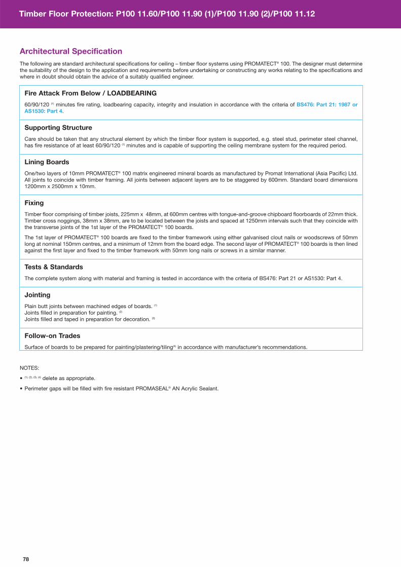
78
Timber Floor Protection: P100 11.60/P100 11.90 (1)/P100 11.90 (2)/P100 11.12
Architectural Specification
The following are standard architectural specifications for ceiling – timber floor systems using PROMATECT® 100. The designer must determine
the suitability of the design to the application and requirements before undertaking or constructing any works relating to the specifications and
where in doubt should obtain the advice of a suitably qualified engineer.
Fire Attack From Below / LOADBEARING
60/90/120 (1) minutes fire rating, loadbearing capacity, integrity and insulation in accordance with the criteria of BS476: Part 21: 1987 or
AS1530: Part 4.
Supporting Structure
Care should be taken that any structural element by which the timber floor system is supported, e.g. steel stud, perimeter steel channel,
has fire resistance of at least 60/90/120 (1) minutes and is capable of supporting the ceiling membrane system for the required period.
Lining Boards
One/two layers of 10mm PROMATECT® 100 matrix engineered mineral boards as manufactured by Promat International (Asia Pacific) Ltd.
All joints to coincide with timber framing. All joints between adjacent layers are to be staggered by 600mm. Standard board dimensions
1200mm x 2500mm x 10mm.
Fixing
Timber floor comprising of timber joists, 225mm x 48mm, at 600mm centres with tongue-and-groove chipboard floorboards of 22mm thick.
Timber cross noggings, 38mm x 38mm, are to be located between the joists and spaced at 1250mm intervals such that they coincide with
the transverse joints of the 1st layer of the PROMATECT® 100 boards.
The 1st layer of PROMATECT® 100 boards are fixed to the timber framework using either galvanised clout nails or woodscrews of 50mm
long at nominal 150mm centres, and a minimum of 12mm from the board edge. The second layer of PROMATECT® 100 boards is then lined
against the first layer and fixed to the timber framework with 50mm long nails or screws in a similar manner.
Tests & Standards
The complete system along with material and framing is tested in accordance with the criteria of BS476: Part 21 or AS1530: Part 4.
Jointing
Plain butt joints between machined edges of boards. (1)
Joints filled in preparation for painting. (2)
Joints filled and taped in preparation for decoration. (3)
Follow-on Trades
Surface of boards to be prepared for painting/plastering/tiling(4) in accordance with manufacturer’s recommendations.
NOTES:
• (1), (2), (3), (4) delete as appropriate.
• Perimeter gaps will be filled with fire resistant PROMASEAL® AN Acrylic Sealant.

79
Mezzanine Floor: P100 12.60
# Margin of error is generally within ±3dB.
Steel joist type 1 – Fire attack from below / Loadbearing
1 1 layer of PROMATECT® 100 board 20mm thick
2 1 layer of PROMATECT® 100 cover strip 100mm wide x 20mm thick
located behind transverse board joint
3 Longitudinal board joint to coincide with steel framework
4 Gap at perimeter to be caulked with
PROMASEAL® AN Acrylic Sealant
5 Steel joist channel 200mm x 65mm x 15mm x 1.5mm thick
at 600mm centres, please consult Promat for minimum/maximum
span dimensions.
6 Tongue-and-groove floorboards 38mm thick
7 35mm x No.8 steel screws at nominal 200mm centres
along all joists
Please refer to pages 90 to 92 for perimeter details and control joints.
T E C H N I C A L D A T A
FRL 60/60/60
STANDARDAS1530: Part 4
APPROVAL BRE CC237274Fir
e R
ati
ng
# STC 36dB
# Rw 36dB
STANDARDISO140: Part 3: 1996
ISO717: Part 1: 1996
PREDICTED Marshall Day
ASSESSMENT 20th Aug 2007
Ac
ou
sti
c
CEILING THICKNESS 253mm
CEILING MASS From 19.44kg/m2
Con
stru
ctio
n
600mm
Nominal
200mm
System Specification
Mezzanine floors are to be constructed using 20mm thick PROMATECT® 100 matrix engineered mineral boards all in accordance with the
Architectural Specificationin the manufacturer’s handbook. Relevant constructions are to be selected according to the required FRL of 60/60/60
of the selected elements. All printed installation details are to be followed to ensure approval to AS1530: Part 4. All work to be certified by
installer in an approved manner.
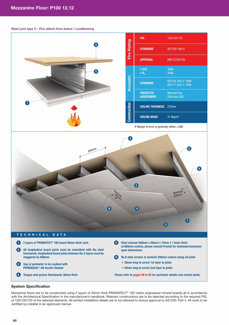
80
Mezzanine Floor: P100 12.12
# Margin of error is generally within ±3dB.
Steel joist type 2 – Fire attack from below / Loadbearing
FRL 120/120/120
STANDARD AS1530: Part 4
APPROVAL BRE CC234729Fir
e R
ati
ng
# STC 39dB
# Rw 39dB
STANDARDISO140: Part 3: 1996
ISO717: Part 1: 1996
PREDICTED Marshall Day
ASSESSMENT 20th Aug 2007
Ac
ou
sti
c
CEILING THICKNESS 278mm
CEILING MASS 31.9kg/m2
Con
stru
ctio
n
Nominal
200mm
600mm
Nominal
200mm
1 2 layers of PROMATECT® 100 board 20mm thick each
2 All longitudinal board joints must be coincident with the steel
framework, longitudinal board joints between the 2 layers must be
staggered by 600mm.
3 Gap at perimeter to be caulked with
PROMASEAL® AN Acrylic Sealant
4 Tongue-and-groove floorboards 38mm thick
5 Steel channel 200mm x 65mm x 15mm x 1.5mm thick
at 600mm centres, please consult Promat for minimum/maximum
span dimensions.
6 No.8 steel screws at nominal 200mm centres along all joists
• 35mm long to screw 1st layer to joists
• 50mm long to screw 2nd layer to joists
Please refer to pages 90 to 92 for perimeter details and control joints.
T E C H N I C A L D A T A
System Specification
Mezzanine floors are to be constructed using 2 layers of 20mm thick PROMATECT® 100 matrix engineered mineral boards all in accordance
with the Architectural Specification in the manufacturer’s handbook. Relevant constructions are to be selected according to the required FRL
of 120/120/120 of the selected elements. All printed installation details are to be followed to ensure approval to AS1530: Part 4. All work to be
certified by installer in an approved manner.

81
Mezzanine Floor: P100 12.60 / P100 12.12
Architectural Specification
The following are standard architectural specifications for ceiling – mezzanine floor systems using PROMATECT® 100. The designer must
determine the suitability of the design to the application and requirements before undertaking or constructing any works relating to the
specifications and where in doubt obtain the advice of a suitably qualified engineer.
Fire Attack From Below / LOADBEARING
60/120* minutes fire rating, loadbearing capacity, integrity and insulation in accordance with the criteria of AS1530: Part 4.
Supporting Structure
Care should be taken that any structural element by which the mezzanine floor system is supported, e.g. steel framing etc, has fire
resistance of at least 60/120* minutes and is capable of supporting the ceiling system for the required duration.
Lining Boards
One/two* layers of 20mm thick PROMATECT® 100 matrix engineered mineral boards as manufactured by Promat International (Asia Pacific)
Ltd. All longitudinal joints to coincide with steel framing. All joints between adjacent layers are to be staggered by 600mm. Standard board
dimensions 1200mm x 2500mm x 20mm.
Fixing
Mezzanine floor comprising of steel joists, 200mm x 65mm x 15mm x 1.5mm, at 600mm centres with tongue-and-groove chipboard
floorboards of 38mm thick.
The first layer of PROMATECT® 100 boards are fixed to the steel framework using 35mm x No.8 steel screws at nominal 200mm centres,
and a minimum of 12mm from the board edge. Where required, one layer of PROMATECT® 100 cover strips 100mm wide x 20mm thick are
located behind the transverse board joints. The second layer of PROMATECT® 100 boards, where required, is then lined against the first
layer and fixed to the steel framework with 50mm x No.8 steel screws at nominal 200mm centres.
Tests & Standards
The complete system along with material and framing is tested and/or assessed to meet the requirements of AS1530: Part 4.
Jointing
Plain butt joints between machined edges of boards. (1)
Joints filled in preparation for painting. (2)
Joints filled and taped in preparation for decoration. (3)
Follow-on Trades
Surface of boards to be prepared for painting/plastering/tiling(4) in accordance with manufacturer’s recommendations.
NOTES:
• *, (1), (2), (3), (4) delete as appropriate.
• Perimeter gaps will be filled with fire resistant PROMASEAL® AN Acrylic Sealant.
82
Chapter 5:
Penetration &
Perimeter DetailingSteel Stud Partitions Window & Door Framings ___________ 83
Steel Stud Partitions Typical Deflectionad Head Details ___ 84
Steel Stud Partitions Base Details _______________________ 85
Steel/Timber Stud Partitions Movement Joints Details ____ 86
Steel Stud Partitions Junction Details ____________________ 87
Solid/Frameless Partitions Connection Details ____________ 89
Ceiling Perimeter Details ________________________________ 90
Ceilings Control Joints Details ___________________________ 92
Penetration Seals _______________________________________ 93
Access Hatches ________________________________________ 95

83
Steel Stud Partitions Window & Door Framings
Detail 2
Detail 1
Detail 3
600/610/625mm
600/610/625mm
Detail 1
Detail 3
Detail 2
1 Boxed studs either side of openings, the studs need to be rigidly fixed top and bottom.
2 Horizontal noggings
3 Stud track
4 Maintain stud spacing above and below window or door openings
5 Expansion bolt at 600mm centres
6 No.8 wafer head screws 16mm long or 3mm steel pop rivets
T E C H N I C A L D A T A

84
Steel Stud Partitions Typical Deflection Head Details
Max
imum
10
0m
mw
ith u
nfixe
d to
p ed
ge
to a
llow
for
mov
emen
t
Max
imum
100m
mw
ith u
nfixe
d to
p ed
ge
to a
llow
for
mov
emen
t
Please refer to pages 43 to 53 for applicable system and FRL.
Consult Promat Technical Department for amendments where
seismic loads are expected.
1 Substrate with a fire resistance at least equivalent to
that of the partition
2 Up to 50mm clearance to allow for expected
building movement
3 Caulk all perimeter gaps to full depth of board with
PROMASEAL® AN Acrylic Sealant to achieve stated fire
and/or acoustic performance
4 Track section with flange fastened to soffit at
maximum 600mm centres
5 Horizontal nogging track
6 40mm x M6 expansion bolts at
minimum 600mm centres
7 Fix board to horizontal nogging track and to vertical
studs only (do not fix through top track)
8 Top track
NOTE: junction may be finished square, with stopping bead or
with cornice. Do not rigidly fix cornice to walls where
movement joints are used.
T E C H N I C A L D A T A
Wall/ceiling junction for substrate
Max
imum
100m
mw
ith u
nfixe
d to
p ed
ge
to a
llow
for
mov
emen
t
Please refer to pages 43 to 53 for applicable system and FRL.
Consult Promat Technical Department for amendments where
seismic loads are expected.
1 Suspended ceiling primary profile
2 Secondary profile where wall runs parallel to setout
3 Fire rated ceiling above
4 Fix top track to channel at maximum 610mm centres to
ceiling framing
5 Horizontal nogging track
6 Fix board to horizontal nogging track and to vertical
studs only (do not fix through top track)
7 Top track
T E C H N I C A L D A T A
Wall/ceiling junction for suspended ceiling
Single layer system
Double layer system

85
Steel Stud Partitions Base Details
Please refer to pages 43 to 53 for applicable system and FRL.
Consult Promat Technical Department for amendments where
seismic loads are expected.
1 PROMATECT® 100 board.
2 Bottom track
3 40mm x M6 expansion anchors at 600mm centres
4 Caulk all perimeter gaps with PROMASEAL® AN Acrylic
Sealant to achieve stated fire and/or acoustic performance
5 Continuous bead of PROMASEAL® AN Acrylic Sealant for
acoustic intergrity
T E C H N I C A L D A T A
Wall base fixing
Single layer system
Double layer system

86
Steel/Timber Stud Partitions Movement Joints Details
15mm
gapPlease refer to pages 54 to 57 for applicable system and FRL.
1 PROMATECT® 100 board.
2 RONDO P35 control joint or similar
3 Flush joints
4 Studs at either side of control joint position
5 PROMASEAL® AN Acrylic Sealant (depth equal to
board thickness) to achieve stated fire and
acoustic performance
6 Non fire rated backing rod 22mm diameter for
acoustic integrity
NOTE: top and bottom tracks must be discontinuous at
control joint.
T E C H N I C A L D A T A
Timber stud frame
100
to 1
50m
m10
mm
Please refer to pages 43 to 53 for applicable system and FRL.
1 Caulk all perimeter gaps with PROMASEAL® AN
Acrylic Sealant to achieve stated fire and/or
acoustic performance
2 RONDO stopping bead or similar and set over
3 Boards situated within profile therefore no fixing of
board to wall stud required
4 M6 expansion bolt 40mm long at 600mm centres
T E C H N I C A L D A T A
Steel stud frame for masonry wall
15mm gapPlease refer to pages 43 to 53 for applicable system and FRL.
1 PROMATECT® 100 board.
2 RONDO P35 control joint or similar
3 Flush joints
4 Studs at either side of control joint position
5 Track discontinuous at control joint
6 PROMASEAL® AN Acrylic Sealant (depth equal to
board thickness) to achieve stated fire and
acoustic performance
7 Backing rod non fire rated 22mm diameter
T E C H N I C A L D A T A
Steel stud frame

87
Steel Stud Partitions Junction Details
Max
imum
100
mm
to fi
rst t
rack
fixi
ng
Fix
at m
axim
um
600
mm
cen
tres
alon
g tra
ck
Please refer to pages 43 to 53 for applicable system and FRL.
1 PROMATECT® 100 board.
2 Set corner with tape and jointing compound
3 40mm x M6 expansion bolts at 600mm centres
4 Screw studs together at maximum
600mm vertical centres
T E C H N I C A L D A T A
Corner
Max
imum
100
mm
to fi
rst t
rack
fixin
g
Fix
at m
axim
um
600
mm
cen
tres
alon
g tra
ck
Please refer to pages 43 to 53 for applicable system and FRL.
1 PROMATECT® 100 board.
2 Set corner with tape and jointing compound
3 40mm x M6 expansion bolts at 600mm centres
4 Additional stud at wall intersection
5 Screw studs together at maximum
600mm vertical centres
T E C H N I C A L D A T A
Intersection

88
Steel Stud Partitions Junction Details
Maximum 100mm
Maximum 600mmPlease refer to pages 43 to 53 for applicable system and FRL.
1 PROMATECT® 100 board.
2 Stud
3 40mm x M6 expansion bolts at 600mm centres
4 Set corner with tape and jointing compound
5 Floor track
T E C H N I C A L D A T A
Wall end
Maxim
um
100mm
Maximum
20mm Please refer to pages 43 to 53 for applicable system and FRL.
1 PROMATECT® 100 board.
2 40mm x M6 expansion bolts at 600mm centres
3 Caulk all perimeter gaps with PROMASEAL® AN
Acrylic Sealant to achieve stated fire and/or
acoustic performance
4 Fix end stud to masonry at maximum
500mm vertical centres
5 Wall stud
T E C H N I C A L D A T A
Masonry wall intersection
Maximum100mm
T E C H N I C A L D A T A
Angled wall intersection
Please refer to pages 43 to 53 for applicable system and FRL.
1 PROMATECT® 100 board.
2 Set corner with tape and jointing compound
3 40mm x M6 expansion bolts at 600mm centres
4 PROMASEAL® AN Acrylic Sealant to maintain fire and
acoustic performance

89
Solid/Frameless Partitions Connection Details
T E C H N I C A L D A T A
Wall base fixing
Please refer to page 58 for applicable system and FRL.
Consult Promat Technical Department for amendments where
seismic loads are expected.
1 PROMATECT® 100 board
2 Galvanised steel angle of appropriate size
3 No.8 self-tapping screws of appropriate length into the
perimeter angle
4 Laminating stitching screws at 300mm centres down
the centre of each board and at board to board joints
5 40mm x M6 masonry anchors at 600mm centres
T E C H N I C A L D A T A
Wall junction fixing
Please refer to page 58 for applicable system and FRL.
Consult Promat Technical Department for amendments where
seismic loads are expected.
1 PROMATECT® 100 board
2 Galvanised steel angle of appropriate size
3 No.8 self-tapping screws of appropriate length into the
perimeter angle
4 Laminating stitching screws at 300mm centres down
the centre of each board and at board to board joints
5 40mm x M6 masonry anchors at 600mm centres
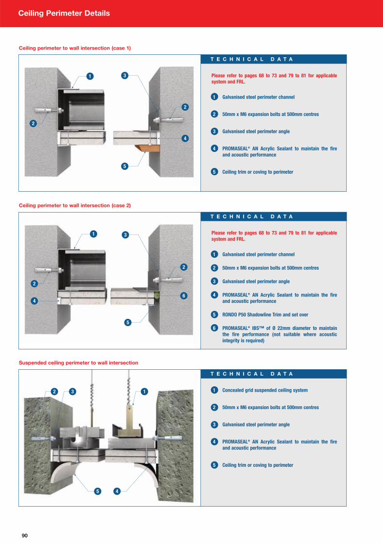
90
Ceiling Perimeter Details
Please refer to pages 68 to 73 and 79 to 81 for applicable
system and FRL.
1 Galvanised steel perimeter channel
2 50mm x M6 expansion bolts at 500mm centres
3 Galvanised steel perimeter angle
4 PROMASEAL® AN Acrylic Sealant to maintain the fire
and acoustic performance
5 Ceiling trim or coving to perimeter
T E C H N I C A L D A T A
Ceiling perimeter to wall intersection (case 1)
Please refer to pages 68 to 73 and 79 to 81 for applicable
system and FRL.
1 Galvanised steel perimeter channel
2 50mm x M6 expansion bolts at 500mm centres
3 Galvanised steel perimeter angle
4 PROMASEAL® AN Acrylic Sealant to maintain the fire
and acoustic performance
5 RONDO P50 Shadowline Trim and set over
6 PROMASEAL® IBS™ of Ø 22mm diameter to maintain
the fire performance (not suitable where acoustic
integrity is required)
T E C H N I C A L D A T A
Ceiling perimeter to wall intersection (case 2)
1 Concealed grid suspended ceiling system
2 50mm x M6 expansion bolts at 500mm centres
3 Galvanised steel perimeter angle
4 PROMASEAL® AN Acrylic Sealant to maintain the fire
and acoustic performance
5 Ceiling trim or coving to perimeter
T E C H N I C A L D A T A
Suspended ceiling perimeter to wall intersection
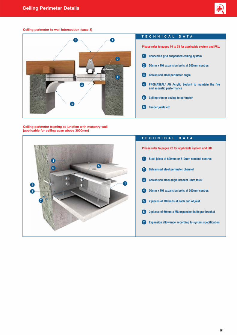
91
Ceiling Perimeter Details
Please refer to pages 74 to 78 for applicable system and FRL.
1 Concealed grid suspended ceiling system
2 50mm x M6 expansion bolts at 500mm centres
3 Galvanised steel perimeter angle
4 PROMASEAL® AN Acrylic Sealant to maintain the fire
and acoustic performance
5 Ceiling trim or coving to perimeter
6 Timber joists etc
T E C H N I C A L D A T A
Ceiling perimeter to wall intersection (case 3)
Please refer to pages 72 for applicable system and FRL.
1 Steel joists at 600mm or 610mm nominal centres
2 Galvanised steel perimeter channel
3 Galvanised steel angle bracket 3mm thick
4 50mm x M6 expansion bolts at 500mm centres
5 2 pieces of M8 bolts at each end of joist
6 2 pieces of 60mm x M8 expansion bolts per bracket
7 Expansion allowance according to system specification
T E C H N I C A L D A T A
Ceiling perimeter framing at junction with masonry wall
(applicable for ceiling span above 3000mm)

92
Ceiling Control Joints Details
60 to 70mm
10 to 15mm gap
Please refer to pages 68 to 73 and 79 to 81 for applicable
system and FRL.
1 RONDO P35 control joint with set finish
2 Concealed steel grid framing sections
3 Continuous Promat board strips
4 Fix one side of Promat board strips with laminating
screws at 200mm centres
T E C H N I C A L D A T A
Parallel to steel framing (single layer)
60 to 70mm
10 to 15mm gap
Please refer to pages 68 to 73 and 79 to 81 for applicable
system and FRL.
1 RONDO P35 control joint with set finish
2 Concealed steel grid framing sections
3 Continuous Promat board strips
4 Continuously fill gap with PROMASEAL® AN Acrylic
Sealant to minimum depth of 1st layer board thickness
5 Fix one side of Promat board strips with laminating screws
at 200mm maximum centres or plaster based adhesive
T E C H N I C A L D A T A
Parallel to steel framing (double layer)
Minimum 200mm
10 to 15mm gap
Please refer to pages 68 to 73 and 79 to 81 for applicable
system and FRL.
1 RONDO P35 control joint with set finish
2 Fix one side of Promat board strips with laminating screws
at 200mm maximum centres or plaster based adhesive
3 Promat board strips between galvanised steel channel
4 Continuously fill gap with PROMASEAL® AN Acrylic
Sealant to minimum depth of 1st layer board thickness
5 Continuous galvanised steel channel
T E C H N I C A L D A T A
Perpendicular to steel framing (double layer)

93
Penetration Seals
1 For FRL up to -/120/120
PROMASEAL® Switchbox Intumescent
(inserted as illustrated bottom left)
2 Steel electrical switchbox 72mm x 72mm x 35mm
3 Electrical wiring
4 Switchbox and socket outlets
5 PROMATECT® 100 partition system
NOTE: Please consult Promat for details of suppliers of fire
resistant electrical switchboxes.
T E C H N I C A L D A T A
Recessed power outlet / Switchbox penetration
1-sided installation 2-sided installation

94
Penetration Seals
1 PROMASEAL® Bulkhead Sealer System, services should
be coated for minimum length of 100mm from
the barrier.
2 1 or 2 layers of rock wool of minimum 120kg/m3
3 Metal pipe/services support system to be within 300mm
on both sides of the barrier
4 Electrical cables
5 Steel cable tray/services support system to be within
100mm on both sides of the barrier
6 Steel ventilation duct/services support system to be
within 300mm on both sides of the barrier
7 PROMATECT® 100 partition system
NOTE: PROMASEAL® AN Acrylic Sealant to be liberally applied
to all joints and contact points between the barrier and
services, and the barrier on the substrate (not shown above).
T E C H N I C A L D A T A
Multiple services penetration through wall
1 PROMATECT® 100 partition system
2 PROMASEAL® FCW wall collar
3 PROMASEAL® FC Retrofit collar
4 Plastic piping, e.g. Polyethylene PE,
Polyvinylchloride PVC, Polypropylene PP.
T E C H N I C A L D A T A
Plastic pipe penetration through wall
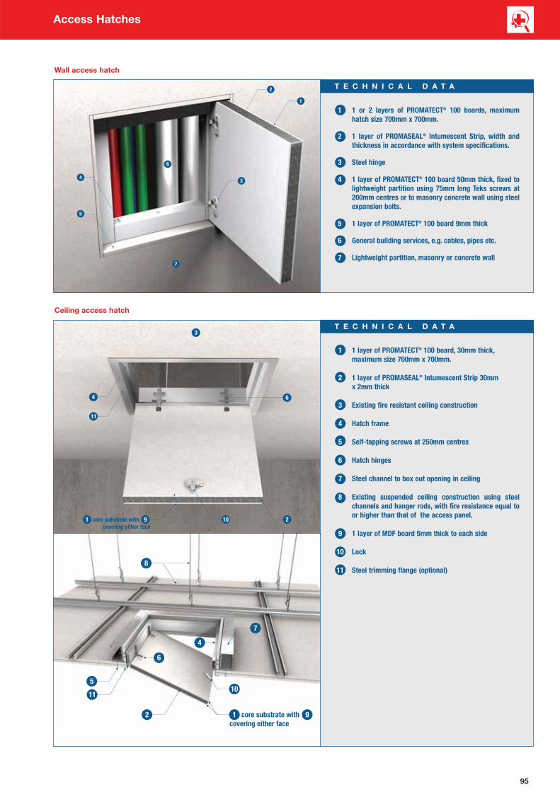
95
Access Hatches
1 1 or 2 layers of PROMATECT® 100 boards, maximum
hatch size 700mm x 700mm.
2 1 layer of PROMASEAL® Intumescent Strip, width and
thickness in accordance with system specifications.
3 Steel hinge
4 1 layer of PROMATECT® 100 board 50mm thick, fixed to
lightweight partition using 75mm long Teks screws at
200mm centres or to masonry concrete wall using steel
expansion bolts.
5 1 layer of PROMATECT® 100 board 9mm thick
6 General building services, e.g. cables, pipes etc.
7 Lightweight partition, masonry or concrete wall
T E C H N I C A L D A T A
Wall access hatch
1 1 layer of PROMATECT® 100 board, 30mm thick,
maximum size 700mm x 700mm.
2 1 layer of PROMASEAL® Intumescent Strip 30mm
x 2mm thick
3 Existing fire resistant ceiling construction
4 Hatch frame
5 Self-tapping screws at 250mm centres
6 Hatch hinges
7 Steel channel to box out opening in ceiling
8 Existing suspended ceiling construction using steel
channels and hanger rods, with fire resistance equal to
or higher than that of the access panel.
9 1 layer of MDF board 5mm thick to each side
10 Lock
11 Steel trimming flange (optional)
T E C H N I C A L D A T A
Ceiling access hatch

96
Chapter 6:
FAQs and Promat
Systems in AustraliaFAQ’s and Promat systems in Australia __________________ 97

97
FAQ’s and Promat Systems in Australia
Q1. Is PROMATECT® 100 cheaper than the conventional
plasterboard systems?
A. Overall system costs must be treated as that, a SYSTEM
COST. This not only includes materials, but also the labour to
install them. With the PROMATECT® 100 system, labour rates
can be cut by up to 40% and more importantly, the project
can be completed much quicker before moving on to another
profitable project.
Q2. How quick can I get PROMATECT® 100?
A. Immediately. We have stock in every state of Australia and
can provide you with the material you require on short notice.
We understand the needs of today’s contractor and will
always strive to meet these expectations. Promat Australia
has a proud history of a high level of service which we always
strive to maintain.
Q3. What technical support can you provide?
A. Our trained and experienced sales staff can provide
certification as well as helpful advice on construction methods
and other aspects of our system. Our systems are fully
designed for the Australian market and are fully compliant to
Australian Standards. Therefore PROMATECT® 100 should be
the board of choice for your fire rated barriers.
Q4. What kind of finish will I get with the PROMATECT® 100
system?
A. The finish will be as good as or better than plasterboard and
is finished using the same techniques you will already be
familiar with.
Q5. Do we need any mineral wool infills?
A. No.
Q6. How come only one layer is needed on each side when
plasterboard needs two or three?
A. PROMATECT® 100 is a very different board to plasterboard
and has superior performance as it is a dedicated fire
resistance board and not a hybrid version of non fire rated
combustible material.
Q7. Is it cost competitive to gypsum board alternatives?
A. It is a one layer system either side of steel stud providing up
to 120 minute protection. Competitor systems are required to
use two layers either side. Labour rates are therefore cut in
half making PROMATECT® 100 a competitive alternative.
Q8. What surface finish am I likely to achieve if
PROMATECT® 100 is used?
A. You will have a finish that is extremely close if not better than
gypsum. The PROMATECT® 100 comes with rebated edges,
that allows it to be set. PROMATECT® 100 can be painted
and used as a finished surface.
Promat system in Australia
PROMATECT® Board systems:Air Ducts, plenums and enclosures
M & E Ducts and trunking
Ceilings and floor protection
Concrete, timber and steel protection
Hatches and Panels
PROMASTOP® Firestopping systems:Pillows
Mortar
Sealants
IBS open cell foam rod and strip
Fyrestrip – high movement gap seals
Collars for plastic pipes
Slab service penetration formers
Brochures:• ProActive Fire Protection Application & Technical Manual
• PROMATECT® 250 PROMAXON® Technology Steelwork Fire
Protection
• PROMAPAINT® Intumescent Coating for fire protection of
steelwork
• The Specifiers Guide to Fire Rated Hatches and Access Panels
• Promat Australia Contractors Guide: Builders
• Promat Australia Contractors Guide: Electricians
• Promat Australia Contractors Guide: HVAC
• Promat Australia Contractors Guide: Plumbers
• Tunnel Fire Protection Handbook
For information on any of the above applications or specialist
advice on
• Custom systems
• Infrastructure
• Energy
• High temperature insulation
• Marine
• Offshore
• Process engineering
please contact your local Promat Australia office listed on the
back cover.

1
2
1 to 3. PROMATECT® 100 boards have been used extensively at
the Ambassador Motel in Frankston, Victoria for partition linings.
4 to 6. 120 minute PROMATECT® 100 steel stud ceilings and
partitions above 6000mm high at Spencer Street Station, Victoria.
3
4
5
6
Project Reference
98

.

6 Distinction Road
Wangara, WA 6065
T (08) 9445 8300
F (08) 9445 8400
progressivematerials.com.au