prominent sigma/1 motor-driven metering pumps … o minent sigma/1-1 prominent ® sigma/1...
TRANSCRIPT
ProM
inen
t
Sigma/1-1
ProMinent®
Sigma/1 Motor-Driven Metering Pumps
Sigma/1 Metering Pumps
Control Versions
Basic type The Sigma basic version (S1Ba) is suitable for simple metering pump applications. The pump may beoperated manually by adjusting the stroke length knob (displacement per stroke). Automatic control ofdisplacement per stroke via a 4-20 mA analog or 3P signal is possible with an optional servomotor. Seeidentity code for motor options.
Control type The Sigma/1 microprocessor controlled metering pump (S1Ca) is supplied with an integral TEFC motor.Pump settings are programmable and viewedon an illuminated LCD. Functions includestroke frequency, batch delivery and externalcontrol by pulse or analog signal.
The Sigma/1 control version features informa-tion displays for flow rate (in gph or l/h) andtotalized flow (gallons or litres); accumulativestroke count with clear/reset capabilities; andstroke length adjustment displayed in incre-ments of 1%. Three LED lights indicate operating status. Options include a programmable access code,flow monitoring, fault and pacing relays, calibration, timer and 4-20 mA output.
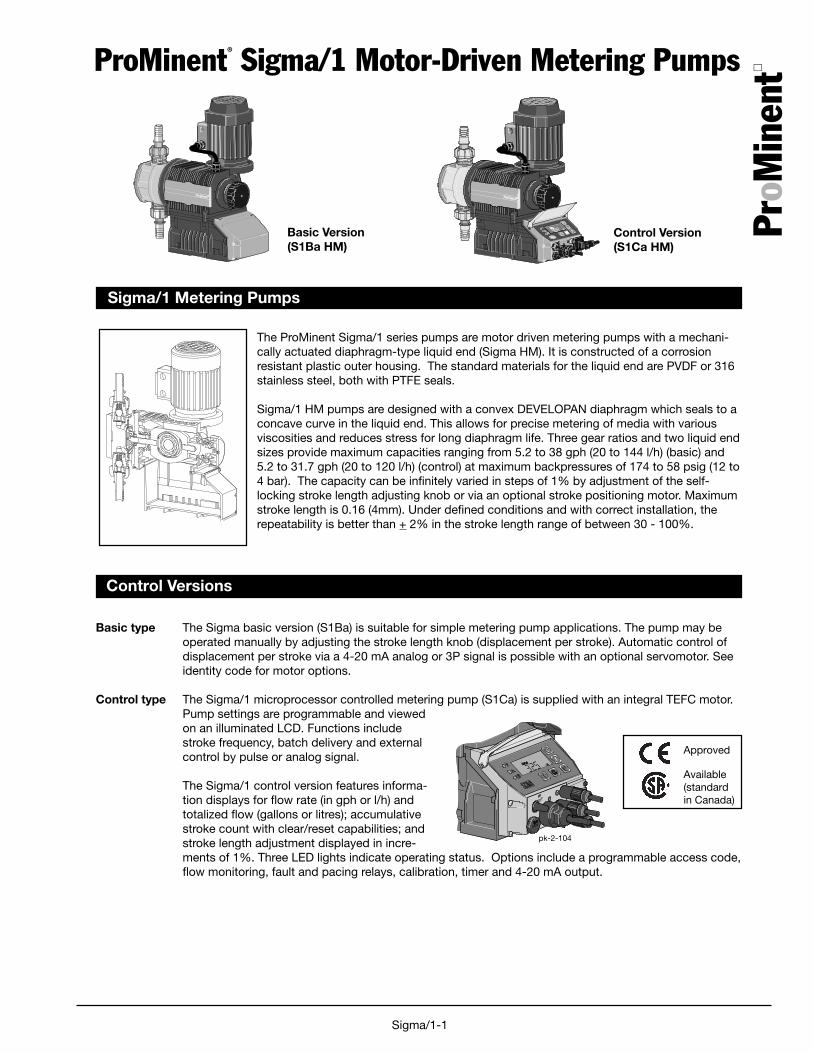
The ProMinent Sigma/1 series pumps are motor driven metering pumps with a mechani-cally actuated diaphragm-type liquid end (Sigma HM). It is constructed of a corrosionresistant plastic outer housing. The standard materials for the liquid end are PVDF or 316stainless steel, both with PTFE seals.
Sigma/1 HM pumps are designed with a convex DEVELOPAN diaphragm which seals to aconcave curve in the liquid end. This allows for precise metering of media with variousviscosities and reduces stress for long diaphragm life. Three gear ratios and two liquid endsizes provide maximum capacities ranging from 5.2 to 38 gph (20 to 144 l/h) (basic) and5.2 to 31.7 gph (20 to 120 l/h) (control) at maximum backpressures of 174 to 58 psig (12 to4 bar). The capacity can be infinitely varied in steps of 1% by adjustment of the self-locking stroke length adjusting knob or via an optional stroke positioning motor. Maximumstroke length is 0.16 (4mm). Under defined conditions and with correct installation, therepeatability is better than + 2% in the stroke length range of between 30 - 100%.
Control Version(S1Ca HM)
Basic Version(S1Ba HM)
Approved
Available(standardin Canada)
pk-2-104
ProM
inen
t
Sigma/1-2
Technical Data: Sigma/1 HM Diaphragm Pumps
Material Liquid end Suction/Discharge Seals BallsCode Connectors
PVT PVDF PVDF PTFE/ Ceramic(Polyvinylidene fluoride) (Polyvinylidene fluoride) Viton®
SST 316 Stainless steel 316 Stainless steel PTFE/ SSViton®
Wetted Materials of Contruction
Technical 60 Hz (1750 RPM) operation Max. Output Max. Max. Suction/ Shippingdata: Capacity at Maximum Stroke per Suction Suction Discharge Weight
Pressure Rate Stroke Lift Pressure Connector w/Motor
Pump Version psig (bar) U.S. (L/h) Stroke/ mL/ (water) psig (bar) DN in. (approx.)S1Ba HM GPH min. stroke ft. (m) lbs. (kg)
12017 PVT 145 (10) 5.2 (20) 88 4 23 (7) 14.5 (1) 10 1/2 MNPT 19.8 (9)12017 SST 174 (12) 5.2 (20) 88 4 23 (7) 14.5 (1) 10 3/8 FNPT 26.5 (12)12035 PVT 145 (10) 11.1 (42) 172 4 23 (7) 14.5 (1) 10 1/2 MNPT 19.8 (9)12035 SST 174 (12) 11.1 (42) 172 4 23 (7) 14.5 (1) 10 3/8 FNPT 26.5 (12)10050 PVT 145 (10) 15.8 (60) 240 4 23 (7) 14.5 (1) 10 1/2 MNPT 19.8 (9)10050 SST 145 (10) 15.8 (60) 240 4 23 (7) 14.5 (1) 10 3/8 FNPT 26.5 (12)
10022 PVT 145 (10) 6.8 (26) 88 5.1 19.6 (6) 14.5 (1) 10 1/2 MNPT 19.8 (9)10022 SST 145 (10) 6.8 (26) 88 5.1 19.6 (6) 14.5 (1) 10 3/8 FNPT 26.5 (12)10044 PVT 145 (10) 14 (53) 172 5.1 19.6 (6) 14.5 (1) 10 1/2 MNPT 19.8 (9)10044 SST 145 (10) 14 (53) 172 5.1 19.6 (6) 14.5 (1) 10 3/8 FNPT 26.5 (12)07065 PVT 102 (7) 20.6 (78) 240 5.1 19.6 (6) 14.5 (1) 10 1/2 MNPT 19.8 (9)07065 SST 102 (7) 20.6 (78) 240 5.1 19.6 (6) 14.5 (1) 10 3/8 FNPT 26.5 (12)
07042 PVT 102 (7) 13.2 (50) 88 9.7 9.8 (3) 14.5 (1) 15 3/4 MNPT 21 (9.5)07042 SST 102 (7) 13.2 (50) 88 9.7 9.8 (3) 14.5 (1) 15 1/2 FNPT 29.8(13.5)04084 PVT 58 (4) 26.7 (101) 172 9.7 9.8 (3) 14.5 (1) 15 3/4 MNPT 21 (9.5)04084 SST 58 (4) 26.7 (101) 172 9.7 9.8 (3) 14.5 (1) 15 1/2 FNPT 29.8(13.5)04120 PVT 58 (4) 38 (144) 240 9.7 9.8 (3) 14.5 (1) 15 3/4 MNPT 21 (9.5)04120 SST 58 (4) 38 (144) 240 9.7 9.8 (3) 14.5 (1) 15 1/2 FNPT 29.8 (13.5)
Sigma/1 Basic Version
Technical 60 Hz operation Max. Output Max. Max. Suction/ Shippingdata: Capacity at Maximum Stroke per Suction Suction Discharge Weight
Pressure Rate Stroke Lift Pressure Connector w/Motor
Pump Version psig (bar) U.S. (L/h) Stroke/ mL/ (water) psig (bar) DN in. (approx.)S1Ca HM GPH min. stroke ft. (m) lbs. (kg)
12017 PVT 145 (10) 5.2 (20) 90 4 23 (7) 14.5 (1) 10 1/2 MNPT 19.8 (9)12017 SST 174 (12) 5.2 (20) 90 4 23 (7) 14.5 (1) 10 3/8 FNPT 26.5 (12)12035 PVT 145 (10) 11.1 (42) 170 4 23 (7) 14.5 (1) 10 1/2 MNPT 19.8 (9)12035 SST 174 (12) 11.1 (42) 170 4 23 (7) 14.5 (1) 10 3/8 FNPT 26.5 (12)10050 PVT 145 (10) 13.2 (50) 200 4 23 (7) 14.5 (1) 10 1/2 MNPT 19.8 (9)10050 SST 145 (10) 13.2 (50) 200 4 23 (7) 14.5 (1) 10 3/8 FNPT 26.5 (12)
10022 PVT 145 (10) 6.8 (26) 90 5.1 19.6 (6) 14.5 (1) 10 1/2 MNPT 19.8 (9)10022 SST 145 (10) 6.8 (26) 90 5.1 19.6 (6) 14.5 (1) 10 3/8 FNPT 26.5 (12)10044 PVT 145 (10) 14 (53) 170 5.1 19.6 (6) 14.5 (1) 10 1/2 MNPT 19.8 (9)10044 SST 145 (10) 14 (53) 170 5.1 19.6 (6) 14.5 (1) 10 3/8 FNPT 26.5 (12)07065 PVT 102 (7) 17.2 (65) 200 5.1 19.6 (6) 14.5 (1) 10 1/2 MNPT 19.8 (9)07065 SST 102 (7) 17.2 (65) 200 5.1 19.6 (6) 14.5 (1) 10 3/8 FNPT 26.5 (12)
07042 PVT 102 (7) 13.2 (50) 90 9.7 9.8 (3) 14.5 (1) 15 3/4 MNPT 21 (9.5)07042 SST 102 (7) 13.2 (50) 90 9.7 9.8 (3) 14.5 (1) 15 1/2 FNPT 29.8(13.5)04084 PVT 58 (4) 26.7 (101) 170 9.7 9.8 (3) 14.5 (1) 15 3/4 MNPT 21 (9.5)04084 SST 58 (4) 26.7 (101) 170 9.7 9.8 (3) 14.5 (1) 15 1/2 FNPT 29.8(13.5)04120 PVT 58 (4) 31.7 (120) 200 9.7 9.8 (3) 14.5 (1) 15 3/4 MNPT 21 (9.5)04120 SST 58 (4) 31.7 (120) 200 9.7 9.8 (3) 14.5 (1) 15 1/2 FNPT 29.8 (13.5)
Sigma/1 Control Version
ProM
inen
t
Sigma/1-3
Technical Data: Sigma/1 HM Diaphragm Pumps
Diaphragm Failure Indicators
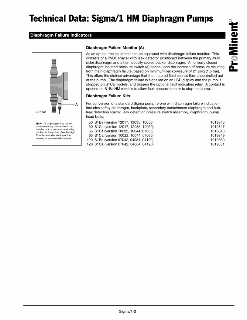
Diaphragm Failure Monitor (A)As an option, the liquid end can be equipped with diaphragm failure monitor. Thisconsists of a PVDF spacer with leak detector positioned between the primary (fluidside) diaphragm and a hermetically sealed backer diaphragm. A normally closeddiaphragm-isolated pressure switch (A) opens upon the increase of pressure resultingfrom main diaphragm failure, based on minimum backpressure of 21 psig (1.5 bar).This offers the distinct advantage that the metered fluid cannot flow uncontrolled outof the pump. The diaphragm failure is signalled on an LCD display and the pump isstopped on S1Ca models, and triggers the optional fault indicating relay. A contact isopened on S1Ba HM models to allow fault annunciation or to stop the pump.
Diaphragm Failure Kits
For conversion of a standard Sigma pump to one with diaphragm failure indication.Includes safety diaphragm, backplate, secondary containment diaphragm and hub,leak detection spacer, leak detection pressure switch assembly, diaphragm, pumphead bolts.
50 S1Ba (version 12017, 12035, 10050) 101984650 S1Ca (version 12017, 12035, 10050) 101984765 S1Ba (version 10022, 10044, 07065) 101984865 S1Ca (version 10022, 10044, 07065) 1019849
120 S1Ba (version 07042, 04084, 04120) 1019850120 S1Ca (version 07042, 04084, 04120) 1019851
Note: All diaphragm-type motor-driven metering pumps should beinstalled with a pressure relief valveon the discharge line. See the High-Flow Accessories section of thecatalog for pressure relief valves.
A
pk_2_003
ProM
inen
t
Sigma/1-4
Specifications: Sigma/1General:
Maximum stroke length: 0.16" (4.0 mm)
Power cord: 6 foot (2 m) 2 wire + ground (supplied on control versions)
Stroke frequency control: S1Ba: Constant speed or optional DC/SCR drive or AC inverterS1Ca: Microprocessor control version with innovative start/stop and variablespeed control proportional to set frequency or external control signal.
Stroke counting: Standard on S1Ca
Materials of constructionHousing: Glass-filled Luranyl™ (PPE)
Wetted materials of construction: Liquid End: PVDF 316 SSSuct./Dis. Connectors: PVDF 316 SSSeals: PTFE/Viton® PTFE/Viton®
Check Balls: Ceramic SSPressure Relief Valves: PVDF/Viton® O-rings SS/Viton® O-rings
Drive: Cam and spring-follower (lost motion)
Lubrication: Sealed grease lubricated bearings and gearing
Warranty: Two years on drive, one year on liquid end.
Factory testing: Each pump is tested for rated flow at maximum pressure.
Industry Standard: CE approved, CSA available (standard in Canada)
Diaphragm materials: PTFE faced EPDM with Nylon reinforcement and steel core
Liquid end options: Polyvinylidene Fluoride (PVDF) or 316 SS, with PTFE faced Viton® seals
Check valves: Single ball check, PVDF and SS versions.Optional springs available (Hastelloy C4)
Repeatability: When used according to the operating instructions, better than ±2%
Max. fluid operating temperatures: Material Constant Short Term(Max. Backpressure) (15 min. @ max.30 psi)
PVDF 149˚F (65˚C) 212˚F (100˚C)316 SS 194˚F (90˚C) 248˚F (120˚C)
Diaphragm failure indication: Optional, see accessories. Switch is N.C., opens to indicate failure.Switch rated 250 VAC, 0.3 A inductive or 0.5 A resistive; 30 VDC,1.0 A resistive.Requires minimum 21 psig (1.5 bar) backpressure on pump. N.O. switchavailable upon request. Includes double diaphragm leak prevention.
Max. solids size in fluid: 0.3 mm
Stroke length adjustment: Manual, in increments of 1%. Motorized stroke length adjustment available.
Sigma/1 Basic Version
Motor: See available motors in identity code
Sigma/1 Control Version
Control Function: At stroke frequencies equal to or greater than 33%, the integral AC variablefrequency drive continuously varies the motor speed in a linear response to theincoming signal. At stroke frequencies less than 33%, the motor starts and stopsaccording to a control algorithm to provide the desired stroke frequency. In thestart-stop mode the motor speed is constant at approximately 580 RPM.
Enclosure rating: NEMA 3 (IP 55)
Motor data: Totally enclosed, fan cooled (IP55); class F insulation; IEC frame; 1/8 HP(0.09 kW) 230 V, 3 phase (0.7 A)
ProM
inen
t
Sigma/1-5
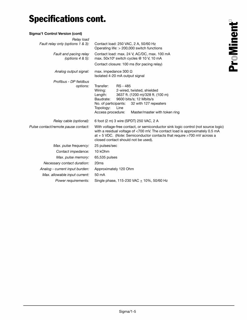
Specifications cont.Sigma/1 Control Version (cont)
Relay loadFault relay only (options 1 & 3): Contact load: 250 VAC, 2 A, 50/60 Hz
Operating life: > 200,000 switch functions
Fault and pacing relay Contact load: max. 24 V, AC/DC, max. 100 mA(options 4 & 5): max. 50x106 switch cycles @ 10 V, 10 mA
Contact closure: 100 ms (for pacing relay)
Analog output signal: max. impedance 300 ΩIsolated 4-20 mA output signal
Profibus - DP fieldbus options: Transfer: RS - 485
Wiring: 2-wired, twisted, shieldedLength: 3637 ft. (1200 m)/328 ft. (100 m)Baudrate: 9600 bits/s; 12 Mbits/sNo. of participants: 32 with 127 repeatersTopology: LineAccess procedure: Master/master with token ring
Relay cable (optional): 6 foot (2 m) 3 wire (SPDT) 250 VAC, 2 A
Pulse contact/remote pause contact: With voltage-free contact, or semiconductor sink logic control (not source logic)with a residual voltage of <700 mV. The contact load is approximately 0.5 mAat + 5 VDC. (Note: Semiconductor contacts that require >700 mV across aclosed contact should not be used).
Max. pulse frequency: 25 pulses/sec
Contact impedance: 10 kOhm
Max. pulse memory: 65,535 pulses
Necessary contact duration: 20ms
Analog - current input burden: Approximately 120 Ohm
Max. allowable input current: 50 mA
Power requirements: Single phase, 115-230 VAC + 10%, 50/60 Hz

ProM
inen
t
Sigma/1-6
Desired capacity min./max. GPH (l/h)______________________
Available power supply ______V, ______ Hz, ______ phase
Working temperature min./max. °F (°C)________________________
Description of process fluid ______________________________
Concentration % ______________________________
Solids content % ______________________________
Absolute viscosity, cP ______________________________
Vapor pressure at working temperature psig (bar) _______________________
Remarks (e.g. abrasive, developing ______________________________gases and fumes, flammable, corrosive) ______________________________
Suction conditions:
Suction lift min./max., or ft. (m) _________________________
Positive suction head min./max., or ft. (m)_________________________
Pressure in chemical tank psig (bar)_______________________
Length of suction line ft. (m) _________________________
Size (I.D.) of suction line in. (mm)_______________________
Number of valves and fittings in suction line ______________________________
Discharge conditions:
Back-pressure min./max. psig (bar) _______________________
Discharge head min./max. ft. (m) _________________________
Negative discharge head min./max. ft. (m) _________________________
Length of discharge line ft. (m) _________________________
Size (I.D.) of discharge line in. (mm)_______________________
Number of valves and fittings in discharge line ______________________________
Data required to sizemetering pumps and accessoriesComplete this data sheet and fax it to ProMinent Pittsburgh at (412) 787-0704 or ProMinent Canada at(519) 836-5226 for a review of the system hydraulics and recommendations on pump and accessoryselection.
System sketch
ProM
inen
t
Sigma/1-7
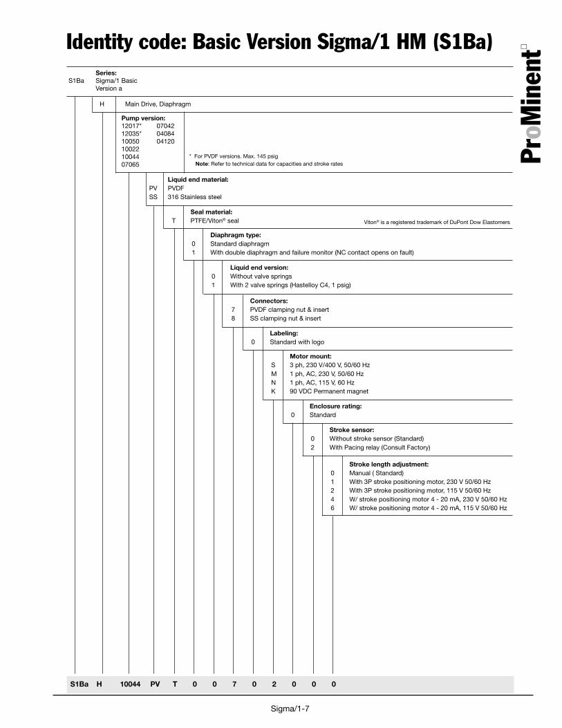
Identity code: Basic Version Sigma/1 HM (S1Ba)Series:
S1Ba Sigma/1 BasicVersion a
H Main Drive, Diaphragm
Pump version:12017* 0704212035* 0408410050 04120100221004407065
S1Ba H 10044 PV T 0 0 7 0 2 0 0 0
Liquid end material:PV PVDFSS 316 Stainless steel
Seal material:T PTFE/Viton® seal
Diaphragm type:0 Standard diaphragm1 With double diaphragm and failure monitor (NC contact opens on fault)
Liquid end version:0 Without valve springs1 With 2 valve springs (Hastelloy C4, 1 psig)
Viton® is a registered trademark of DuPont Dow Elastomers
Connectors:7 PVDF clamping nut & insert8 SS clamping nut & insert
Labeling:0 Standard with logo
Motor mount:S 3 ph, 230 V/400 V, 50/60 HzM 1 ph, AC, 230 V, 50/60 HzN 1 ph, AC, 115 V, 60 HzK 90 VDC Permanent magnet
Stroke sensor:0 Without stroke sensor (Standard)2 With Pacing relay (Consult Factory)
Enclosure rating:0 Standard
Stroke length adjustment:0 Manual ( Standard)1 With 3P stroke positioning motor, 230 V 50/60 Hz2 With 3P stroke positioning motor, 115 V 50/60 Hz4 W/ stroke positioning motor 4 - 20 mA, 230 V 50/60 Hz6 W/ stroke positioning motor 4 - 20 mA, 115 V 50/60 Hz
* For PVDF versions. Max. 145 psig Note: Refer to technical data for capacities and stroke rates
ProM
inen
t
Sigma/1-8
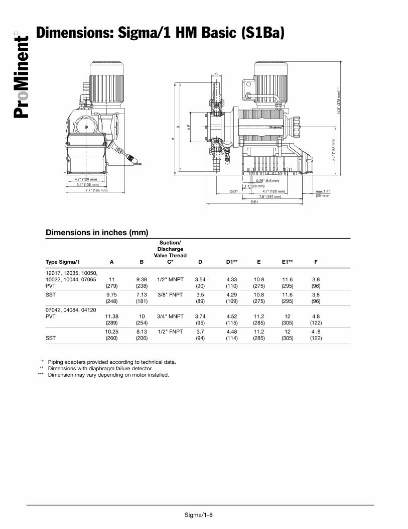
Dimensions: Sigma/1 HM Basic (S1Ba)
7.7" (196 mm)
5.4" (136 mm)
4.7" (120 mm)
A
B Fmax.1.4"(36 mm)
E/E1
D/D1
1.1" (28 mm)
0.25" (6.5 mm)
4.7" (120 mm)
7.8" (197 mm)
6.3"
(160
mm
)
14.9
" (3
78 m
m)*
**
C
Suction/Discharge
Valve ThreadType Sigma/1 A B C* D D1** E E1** F
12017, 12035, 10050,10022, 10044, 07065 11 9.38 1/2" MNPT 3.54 4.33 10.8 11.6 3.8PVT (279) (238) (90) (110) (275) (295) (96)
SST 9.75 7.13 3/8" FNPT 3.5 4.29 10.8 11.6 3.8(248) (181) (89) (109) (275) (295) (96)
07042, 04084, 04120PVT 11.38 10 3/4" MNPT 3.74 4.52 11.2 12 4.8
(289) (254) (95) (115) (285) (305) (122)
10.25 8.13 1/2" FNPT 3.7 4.48 11.2 12 4 .8SST (260) (206) (94) (114) (285) (305) (122)
Dimensions in inches (mm)
* Piping adapters provided according to technical data.** Dimensions with diaphragm failure detector.
*** Dimension may vary depending on motor installed.
ProM
inen
t
Sigma/1-9
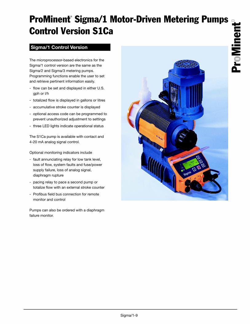
ProMinent® Sigma/1 Motor-Driven Metering PumpsControl Version S1Ca
Sigma/1 Control Version
The microprocessor-based electronics for theSigma/1 control version are the same as theSigma/2 and Sigma/3 metering pumps.Programming functions enable the user to setand retrieve pertinent information easily.
- flow can be set and displayed in either U.S.gph or l/h
- totalized flow is displayed in gallons or litres
- accumulative stroke counter is displayed
- optional access code can be programmed toprevent unauthorized adjustment to settings
- three LED lights indicate operational status
The S1Ca pump is available with contact and4-20 mA analog signal control.
Optional monitoring indicators include
- fault annunciating relay for low tank level,loss of flow, system faults and fuse/powersupply failure, loss of analog signal,diaphragm rupture
- pacing relay to pace a second pump ortotalize flow with an external stroke counter
- Profibus field bus connection for remotemonitor and control
Pumps can also be ordered with a diaphragmfailure monitor.

ProM
inen
t
Sigma/1-10
Sigma/1 Microprocessor ControlStandard Control Modes and Functions
Feed rate is determined by strokelength and stroke rate. Strokelength is manually adjustable from1 to 100% in increments of 1% viathe stroke length knob.
Stroke rate can be set to a maxi-mum of 90, 170 or 200 strokes perminute (pump dependent). Anilluminated LCD displays strokelength, stroke rate and an accumu-lative stroke counter, which can becleared and reset.
Pump capacity output is displayedin either U.S. gph or l/h, set by theoperator. Output is accumulatedand totalized capacity is alsodisplayed in either U.S. gallons orlitres.
The “i” key is used to scrollinformation screens for stroke rate,stroke length, stroke counter,capacity and totalized capacity.Other information is availabledepending on control mode.
Control Modes
The control modes available withthe Sigma/1 include manual,external contact with pulse control(multiplier/divider), batch, or analogcontrol. The Profibus optionincludes all control modes, plusfieldbus connection.
In the “Manual” mode, stroke rateis controlled manually. The“Contact” external mode allowsadjustments to be made externally(e.g. by means of a pulse-typewater meter for proportionalchemical feed). Pulse signals arefed into the contact input of thepump by an optional control cable.Each pulse from a water meter orpulse-type controller provides thepump an input to pump at theselected pulse ratio, up to thepump's maximum stroke rate.Over-stroking the pump is notpossible.
Standard Functions
“Calibrate”The pump can be directly cali-brated in-line to actual flow.Calibration is maintained within thestroke frequency range of 90/170/200 spm (model dependent). Awarning indicator flashes whenadjustments to the stroke volumeare made outside the calibratedrange of +/- 10%.
“Auxiliary Frequency”An auxiliary frequency can beprogrammed. This default strokingrate can be enabled via theoptional control cable.
“Flow”The Sigma/1 series meteringpumps will monitor their ownoutput, with an optional adjustableflow monitor. Every fluid dischargeis sensed and fed back to theelectronic control circuit of thepump. If insufficient fluid isdischarged for a predeterminednumber of strokes (up to 125), thepump automatically stops and thered LED lights. The optional faultrelay changes state to issue analarm or activate a standby pump.Call for availability. Ensure fluid fl
“Float Switch”An optional two-stage ProMinentfloat switch can be plugged intothe pump to monitor chemical tanklevels. An early warning is issuedwhen the allowable minimum levelis reached. The pump continues tooperate while the display flashes,the yellow LED lights and anoptional collective fault relaychanges state to issue an alarm. Ifthe liquid level in the supply tankdrops another 3/4" (20 mm), thepump automatically shuts down,the LCD displays “Minim” and the
red LED lights. The optional faultrelay remains activated.
“Pause”The Sigma/1 series can be re-motely started and stopped via adry contact through the optionalcontrol cable.
“Stop”The Sigma/1 can be stopped bypressing the STOP/START keywithout disconnecting from thepower supply.
“Prime”Priming is activated by pressingboth arrow keys at the same timewhile the frequency display isshowing.
Function and Error Indicators
Three LED lights on the pumpfaceplate signal operational status.The green light flashes duringnormal operation, and the yellowlight warns of a situation that couldlead to a fault (e.g. low chemical).If a fault occurs “error” will appearon the LCD screen and the red LEDlight appears.

ProM
inen
t
Sigma/1-11
Optional Control Modes
“Analog” Mode
With this option, the stroking rate ofthe Sigma/1 is directly proportionalto the analog signal. For a customrange setting, the curve feature ofthe analog input can be selected.With this, the pump response to theanalog input can be easily pro-grammed.
“Contact” Mode with PulseControl
This feature is used to “tune” thepump to contact generators of anykind (e.g. pulse-type water meter orprocess controller), and eliminatethe need for a costly externalcontrol unit. The following func-tions can be selected by means ofthe keypad.
Pulse step-up (multiply) andstep-down (divide)
By simply entering a factor in the0.01-99.99 range, the step-up orstep-down ratio is set.
For example:
Step-up Factor:99.99 1 pulse = 99.99 pump strokes10 1 pulse = 10 pump strokes
Step-down Factor:0.25 4 pulses = 1 pump stroke0.01 100 pulses = 1 pump stroke
“Batch” Mode
The Batch mode is a variation ofthe contact operating mode. Anumber of strokes can be predeter-mined up to 65,535 strokes (wholenumbers) or the feed quantity canbe predetermined. The batch isthen initiated by either pressing the"P" key on the pump face orproviding a contact to the externalcontrol cable.
Access Code
A programmable access code toprevent unauthorized changes tosettings is available as an option.
Sigma/1Optional Control Modes and Features
Relay outputs. . .
Fault annunciating relay
For low tank level (flow switch), lossof flow (flow monitor), loss ofanalog signal and diaphragmrupture monitor, system faults andfuse/power supply failure.
Fault annunciating and Pacingrelay
In addition to the fault annunciatingrelay, a contact closure is issuedwith every pump stroke (contactduration 150 ms). This allows asecond ProMinent metering pumpto be paced synchronously, or tototalize flow with an external strokecounter.
4-20 mA Analog Output
A 4-20 mA analog output option isavailable for use with pumps thatoperate in the manual mode or by aremote 4-20 mA analog referencesignal. The 4-20 mA analog outputsignal is linear to pump frequencymultiplied by the percentage ofstroke length. The output signal isisloated and can drive up to 300Ohms impedance. Analog outputcan be used for status feedback tohigher level control systems forclosed loop control or for monitor-ing chemical usage. This option isavailable in combination with eitherthe fault annunciating or pacingrelay.
Timer Relay
The optional integrated 2-weektimer offers 81 programmableevents. It can be set to hourly, daily,work days, weekend, weekly ortwo-week periods with switch-ontimes from 1 second to two weeks.The timer can be programmed tochange operation mode, frequencyand the function of two relays. Allthe functions can be programmedindependently of one another. Upto 13 delay times can be pro-grammed into the timer function.
The range of applications exceedsthat of a "standard timer". Typicalapplication is disinfection in coolingtowers, process water, etc. with theability to automatically programshock dosages or increase theconcentration at a certain interval.
Fieldbus connection
Monitor and control remotely via aSCADA/PLC system using theprofibus-DP system.
Note: Relay options not availablewith profibus. Profibus is not fieldretrofittable.
An externalpanel enablesoptional relaysto be installedon-site.
onoff
ProM
inen
t
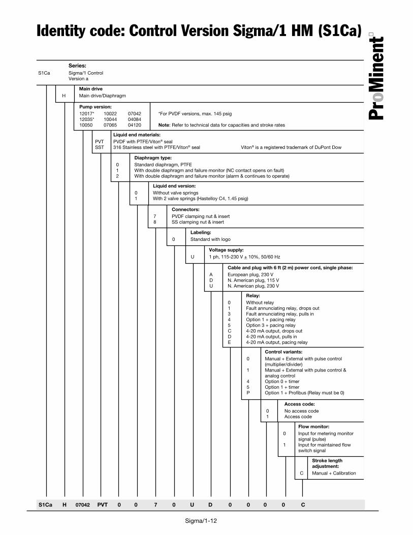
Sigma/1-12
Stroke lengthadjustment:
C Manual + Calibration
Flow monitor:0 Input for metering monitor
signal (pulse)1 Input for maintained flow
switch signal
Access code:0 No access code1 Access code
Control variants:0 Manual + External with pulse control
(multiplier/divider)1 Manual + External with pulse control &
analog control4 Option 0 + timer5 Option 1 + timerP Option 1 + Profibus (Relay must be 0)
Relay:0 Without relay1 Fault annunciating relay, drops out3 Fault annunciating relay, pulls in4 Option 1 + pacing relay5 Option 3 + pacing relayC 4-20 mA output, drops outD 4-20 mA output, pulls inE 4-20 mA output, pacing relay
Cable and plug with 6 ft (2 m) power cord, single phase:A European plug, 230 VD N. American plug, 115 VU N. American plug, 230 V
Voltage supply:U 1 ph, 115-230 V + 10%, 50/60 Hz
Labeling:0 Standard with logo
Connectors:7 PVDF clamping nut & insert8 SS clamping nut & insert
Liquid end version:0 Without valve springs1 With 2 valve springs (Hastelloy C4, 1.45 psig)
Diaphragm type:0 Standard diaphragm, PTFE1 With double diaphragm and failure monitor (NC contact opens on fault)2 With double diaphragm and failure monitor (alarm & continues to operate)
Liquid end materials:PVT PVDF with PTFE/Viton® sealSST 316 Stainless steel with PTFE/Viton® seal Viton® is a registered trademark of DuPont Dow
Pump version:12017* 10022 07042 *For PVDF versions, max. 145 psig12035* 10044 0408410050 07065 04120 Note: Refer to technical data for capacities and stroke rates
Main drive H Main drive/Diaphragm
Series:S1Ca Sigma/1 Control
Version a
S1Ca H 07042 PVT 0 0 7 0 U D 0 0 0 0 C
Identity code: Control Version Sigma/1 HM (S1Ca)
ProM
inen
t
ProM
inen
t
Sigma/1-13
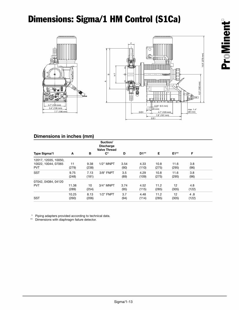
Dimensions: Sigma/1 HM Control (S1Ca)
A
B F
E/E1
D/D1
C
7.7" (196 mm)
5.4" (136 mm)
4.7" (120 mm)
1.1" (28 mm)
0.25" (6.5 mm)
4.7" (120 mm)max. 1.4"(36 mm)
7.8" (197 mm)
6.3"
(160
mm
)
14.9
" (3
78 m
m)
Suction/Discharge
Valve ThreadType Sigma/1 A B C* D D1** E E1** F
12017, 12035, 10050,10022, 10044, 07065 11 9.38 1/2" MNPT 3.54 4.33 10.8 11.6 3.8PVT (279) (238) (90) (110) (275) (295) (96)
SST 9.75 7.13 3/8" FNPT 3.5 4.29 10.8 11.6 3.8(248) (181) (89) (109) (275) (295) (96)
07042, 04084, 04120PVT 11.38 10 3/4" MNPT 3.74 4.52 11.2 12 4.8
(289) (254) (95) (115) (285) (305) (122)
10.25 8.13 1/2" FNPT 3.7 4.48 11.2 12 4 .8SST (260) (206) (94) (114) (285) (305) (122)
Dimensions in inches (mm)
* Piping adapters provided according to technical data.** Dimensions with diaphragm failure detector.

ProM
inen
t
Sigma/1-14
ProMinent® Sigma/1Metering monitor
Description Part No.
Metering monitor
Adjustable metering monitor “Flow Control”For S1Ca HM with connection cable for assembly directly to liquid end.
Monitors individual strokes according to the float and orifice principle. The partial quantity of chemical flowing past thefloat is adjusted from the total stroke volume via the adjusting screw so that an alarm is actuated if there is no pumpflow. The user can select the number of incomplete strokes permitted (between 1 and 125) in accordance with the actualprocess requirements.
Materials:
Flow meter: PVDFFloat: PTFE-coatedSeals: Viton® B/EPDM
Call for details.
Pump
Flow monitor
[For use with low-viscosity (water-like) fluids only].
ProM
inen
t
Sigma/1-15
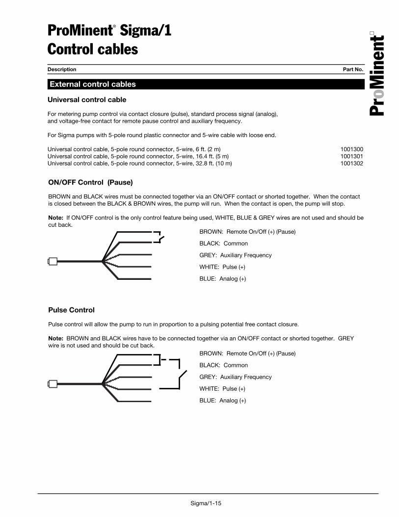
ProMinent® Sigma/1Control cablesDescription Part No.
Universal control cable
For metering pump control via contact closure (pulse), standard process signal (analog),and voltage-free contact for remote pause control and auxiliary frequency.
For Sigma pumps with 5-pole round plastic connector and 5-wire cable with loose end.
Universal control cable, 5-pole round connector, 5-wire, 6 ft. (2 m) 1001300Universal control cable, 5-pole round connector, 5-wire, 16.4 ft. (5 m) 1001301Universal control cable, 5-pole round connector, 5-wire, 32.8 ft. (10 m) 1001302
External control cables
Pulse Control
Pulse control will allow the pump to run in proportion to a pulsing potential free contact closure.
Note: BROWN and BLACK wires have to be connected together via an ON/OFF contact or shorted together. GREYwire is not used and should be cut back.
BROWN: Remote On/Off (+) (Pause)
BLACK: Common
GREY: Auxiliary Frequency
WHITE: Pulse (+)
BLUE: Analog (+)
ON/OFF Control (Pause)
BROWN and BLACK wires must be connected together via an ON/OFF contact or shorted together. When the contactis closed between the BLACK & BROWN wires, the pump will run. When the contact is open, the pump will stop.
Note: If ON/OFF control is the only control feature being used, WHITE, BLUE & GREY wires are not used and should becut back.
BROWN: Remote On/Off (+) (Pause)
BLACK: Common
GREY: Auxiliary Frequency
WHITE: Pulse (+)
BLUE: Analog (+)
ProM
inen
t
Sigma/1-16
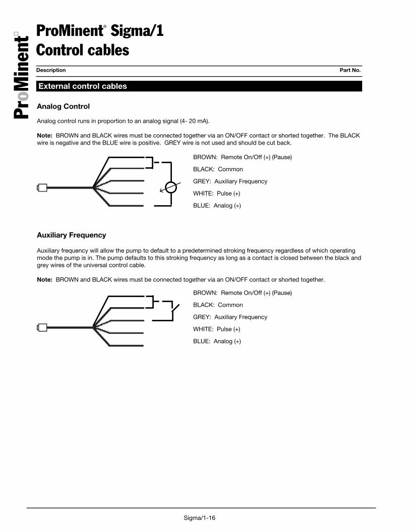
ProMinent® Sigma/1Control cablesDescription Part No.
Auxiliary Frequency
Auxiliary frequency will allow the pump to default to a predetermined stroking frequency regardless of which operatingmode the pump is in. The pump defaults to this stroking frequency as long as a contact is closed between the black andgrey wires of the universal control cable.
Note: BROWN and BLACK wires must be connected together via an ON/OFF contact or shorted together.
BROWN: Remote On/Off (+) (Pause)
BLACK: Common
GREY: Auxiliary Frequency
WHITE: Pulse (+)
BLUE: Analog (+)
External control cables
Analog Control
Analog control runs in proportion to an analog signal (4- 20 mA).
Note: BROWN and BLACK wires must be connected together via an ON/OFF contact or shorted together. The BLACKwire is negative and the BLUE wire is positive. GREY wire is not used and should be cut back.
BROWN: Remote On/Off (+) (Pause)
BLACK: Common
GREY: Auxiliary Frequency
WHITE: Pulse (+)
BLUE: Analog (+)

ProM
inen
t
Sigma/1-17
ProMinent Sigma/1Spare Parts Spare Parts and Liquid Ends
ValveComplete
C
A
Liquid Dim A Dim CEnd (mm) (mm)
FM 50 70 32FM 65 70 37FM 120 86.5 51
Complete liquid ends include pump head, valves, mounting screws, diaphragm andbackplate. Clamping nuts and inserts are not included with complete liquid ends,complete valves or spare parts kits (see the High Flow Accessories section for theseparts). Spare parts kits include:
PVT Liquid ends SST Liquid ends
1 Diaphragm 1 Diaphragm1 Suction valve 2 Valve balls1 Discharge valve 1 Set of seals2 Valve balls1 Set of seals
Material Liquid End Spare PartsCode Complete Kit Valve Complete Diaphragm
12017, 12035, 10050 with Liquid end FM 50
PVT 1010560 1010541 1002267 1010279SST 1010561 1010555 809459 1010279SST* 1010554 1010279
10022, 10044, 07065 with Liquid end FM 65
PVT 1010562 1010542 1002267 1010282SST 1010563 1010557 809459 1010282SST* 1010556 1010282
07042, 04084, 04120 with Liquid end FM 120
PVT 1010565 1010543 792517 1010285SST 1010566 1010559 809404 1010285SST* 1010558 1010285
* Without valves
ProM
inen
t
Sigma/1-18Sigma/1 HM-1
((THIS IS A MASTER, EDIT FOR SPECIFIC APPLICATION))PROMINENT FLUID CONTROLS, INC. - SIGMA/1 HM (for flow rates from 5 to 38 gph)
PART 1 - GENERAL
1.1 GENERALA. This specification covers the supply, installation, and testing of a complete functional meter-
ing pump system including all accessories and appurtenances as shown on the drawings anddescribed herein. A single chemical metering pump manufacturer shall be responsible forsupplying all components of the metering feed system.
1.2 QUALITY ASSURANCE A. For the purpose of establishing quality assurance, experience, and system reliability, the
products described herein are based on those metering pumps manufactured by ProMinentFluid Controls, Inc. All pumps shall be shop-tested for capacity at rated pressure prior toshipment, with documented results provided.
1.3 WARRANTYA. The chemical metering pump manufacturer shall provide a two year warranty on the meter-
ing pump mechanical drive and one year on the liquid end.
PART 2 - PRODUCTS
2.1 GENERALA. Manufacturers:
1. ProMinent Fluid Controls, Inc.2. Pre-approved equal.
2.2 DESCRIPTIONA. The chemical metering pump shall be a simplex, motor-driven, reciprocating, mechanically-
actuated diaphragm type. The pump shall include integral motor, permanently lubricatedgear reducer, cam-and-spring drive mounted and sealed in a non-corrosive plastic outer,with heat sinks for cooling.
B. The power supply shall be ___VAC, ___Hz, ___Phase.C. The liquid end shall be physically separated from the drive unit by a back plate with weep
hole creating air gap separation. An elastomer shaft wiper seal shall prevent contaminationof the gear box by confining chemical within the back plate if the primary diaphragm fails.The primary diaphragm shall have a steel core, vulcanized into a nylon-reinforced EPDMbacking, with PTFE-faced fluid contact surface.
D. ((OPTIONAL)) The liquid end shall also feature a secondary diaphragm separated from theprimary diaphragm by a spacer plate with diaphragm-isolated pressure switch to close acontact for alarm annunciation and to prevent chemical spill or intrusion into pump driveupon failure of the primary diaphragm.
2.3 LIQUID ENDA. The diaphragm shall be of a convex design fitting into a concave liquid end to minimize
diaphragm wear, liquid end dead volume, and to promote flow of solids in suspension.
ProM
inen
t
Sigma/1-19Sigma/1 HM-2
((SELECT ONE))- The liquid end shall be virgin PVDF. The suction and discharge valve shall be PVDF with
PTFE faced Viton gasket seals and ceramic valve balls.Or- The liquid end shall be 316 stainless steel. The suction and discharge valves shall be 316
stainless steel with PTFE-faced Viton gasket seals and stainless steel valve balls.
2.4 CONTROL ((BASIC VERSION PUMP))A. Stroke length control of the basic version pump
((SELECT ONE))- shall be adjustable manually by means of a stroke length knob, in increments of 1.0%, from
0% to 100% of stroke length.Or- shall be adjustable by means of a stroke positioning motor from 0% to 100% of stroke
length. The stroke positioning motor shall feature visual stroke length indication andmanual/ external selector switch for local control via toggle switch or external control inproportion to a 4-20 mA signal.
B. Stroke frequency control of the basic version pump((SELECT ONE))
- shall be fixed at the pump’s maximum stroke rate. Pump shall include a 1/8 HP, TEFC,four-pole AC motor.
Or- shall be controlled by DC SCR drive system for stroke frequency control. The SCR shall
include a wall mountable NEMA 4 enclosure with on/off switch, manual/external switch andspeed potentiometer. The DC voltage output to the motor shall be proportional to the poten-tiometer setting in manual mode, or proportional to an external 4-20 mA signal in externalmode. Pump shall include a 1/8 HP, TENV, permanent magnet 90V DC motor.
Or- shall be controlled by an AC inverter system for stroke frequency control. The inverter shall
include a wall mountable NEMA 4/12 enclosure with keypad and display of % load oroutput voltage. Selectable for local or remote operation via 4-20 mA signal. Pump shallinclude a 1/8 HP, inverter duty, 3-phase, 208-230 VAC motor. Minimum speed 3-30 Hz.
2.5 PROGRAMMING AND CONTROL ((CONTROL VERSION PUMP))A. The metering pump shall be microprocessor-controlled. All pumping functions shall be set
by membrane-switch keypad and status shall be displayed on an illuminated LCD, which isreadable at an offset of 45 degrees. Keypad will allow for simple scrolling of programmedparameters.
B. Stroke length control shall be adjustable manually by means of a stroke length, in incre-ments of 1.0%, from 0 to 100% of stroke length. The LCD shall digitally display strokelength in 1% increments in the full range between 100% and 0%.
C. Programming shall allow pump to be calibrated so as to display pump output in gallons/houror liters/hour. Calibration shall be maintained when stroke length is altered up to plus orminus 10% on the stroke length knob. If stroke length is altered by more than +/-10%, ayellow warning light will light and a flashing message “calib” will appear.
D. The pump shall be equipped with the programmable function of electronic interlocking ofthe keypad by access code to prevent unauthorized adjustments to the pump.
ProM
inen
t
Sigma/1-20Sigma/1 HM-3
E. Keypad shall allow for scrolling and display on LCD such parameters as stroke frequency,stroke length, stroke counter, pump output in gals/hr or l/hr, dosing quantity, mA input beingreceived by pump, and indication of external mode.
F. An AC inverter shall be integral to the microprocessor control and function of the pump.While 115VAC or 230VAC, 1 phase may be used to power the pump, the inverter shall drivea 1/8 HP, 230VAC, 3 phase motor. Stroke frequency shall be accomplished through micro-processor control with proportional start/stop of the motor, from 0% to 33% of stroke rate.Stroke rate shall be accomplished through variable speed of the motor from 34% to 100% ofstroke rate. Stroke frequency control shall be manually adjusted by touch keypads, with theset stroke rate displayed on the LCD. The pump shall be capable of receiving a pulse inputvia optional external control cable such that one pulse gives one pump stroke rate. Thepump shall be capable of remote ON-OFF operation using the pause function via a voltagefree contact relay through an optional control cable. In addition, the pump shall be config-ured with;
((OPTIONAL SELECTIONS))- pulse multiplier/divider functionality. The pump shall allow factoring to issue from 1 to
99.99 strokes per pulse input or to issue 1 stroke per 1 to 100 input pulses.Or- analog input functionality. The pump shall accept an analog signal such that stroke fre-
quency is proportional to 0/4-20mA or 20-4/0mA, the choice of which is programmed at thepump. The pump shall allow the setting of a maximum stroke rate, which corresponds tothe maximum analog signal, with stroke rate proportional to signal strength below that rate.Programming for curve processing shall also be possible, in which any stroke frequencyratio in proportion to the electrical signal can be configured. Analog to digital convertersexternal to the pump shall not be acceptable.
Or- pulse multiplier/divider and analog input functionality. The pump shall allow factoring to
issue from 1 to 99.99 strokes per pulse input or to issue 1 stroke per 1 to 100 input pulses.The pump shall also accept an analog signal such that stroke frequency is proportional to 0/4-20mA or 20-4/0mA, the choice of which is programmed at the pump. The pump shallallow the setting of a maximum stroke rate, which corresponds to the maximum analogsignal, with stroke rate proportional to signal strength below that rate. Programming forcurve processing shall also be possible, in which any stroke frequency ratio in proportion tothe electrical signal can be configured. Analog to digital converters external to the pumpshall not be acceptable.
Or- programmable timer functionality. The pump shall be configured with an integral, program-
mable 2-week, 81 event timer to change operational state of the pump. Timers external tothe metering pump are not acceptable.
Or - pulse multiplier/divider, analog input, and programmable timer functionality (as described
above).
G. The pump shall be equipped with the programmable function of auxiliary frequency control,allowing for quick priming of the pump or for slug feed of process during initial start upafter shutdown. Stroke frequency shall be programmable to the maximum for the pump,and the auxiliary frequency function shall be capable of interfacing with a contact closurerelay for control purposes.
ProM
inen
t
Sigma/1-21Sigma/1 HM-4
2.6 FLOW ASSURANCE ((OPTIONAL))
A. Low Level Control - A 2-stage Float Switch shall be supplied to stop the pump prior tolosing prime and annunciate low level on the pump LED.
B. Relay Output - An SPDT relay shall be installed on the pump for:((SELECT ONE))- fault indication. ((OPTIONAL)) The metering pump shall have an integral relay to allow
remote annunciation of a fault condition (i.e. low supply solution early warning/lack ofsupply solution shut down, loss of chemical output, system faults, and fuse/power supplyfailure). Configure as ((N/O//N/C)) contact closure relay.
Or- both fault indication and pacing relay. ((OPTIONAL)) The metering pump shall have an
integral relay to allow remote annunciation of a fault condition (i.e. low supply solutionearly warning/lack of supply solution shut down, loss of chemical output, system faults, andfuse/power supply failure). Configure as ((N/O//N/C)) contact closure relay. The pumpshall also have an integral relay to issue a contact closure with every pump stroke to pace asecond metering pump. The pacing relay shall be electrically isolated via an optical couplerwith a semiconductor switch.
Or- both 4-20mA output and fault indication. ((OPTIONAL)) The analog output function shall
be a multiplicative factor of both stroke length % and stroke frequency %, reflecting the realtime output capacity of the metering pump. The metering pump shall also have an integralrelay to allow remote annunciation of a fault condition (i.e. low supply solution early warn-ing/lack of supply solution shut down, loss of chemical output, system faults, and fuse/power supply failure). Configure as ((N/O//N/C)) contact closure relay.
Or- both 4-20mA output and pacing relay. ((OPTIONAL)) The analog output function shall be
a multiplicative factor of both stroke length % and stroke frequency %, reflecting the realtime output capacity of the metering pump. The pump shall also have an integral relay toissue a contact closure with every pump stroke to pace a second metering pump. The pacingrelay shall be electrically isolated via an optical coupler with a semiconductor switch.
2.7 ACCESSORIES ((ALL ARE OPTIONAL AND MAY BE INCLUDED AS SEPARATEITEMS OR AS COMPONENTS OF A PUMP STAND))A. The pump shall be mounted on a ((CHOOSE ONE: black, UV-protected polypropylene//
304 stainless steel//FRP grating)) support stand suitable for wall, floor or top-of-tank mount-ing. A single chemical metering pump manufacturer shall be responsible for supplying andassembling all components of the skid, in addition to testing the skid-mounted meteringsystem under conditions of maximum rated pump pressure, prior to shipment. The standshall include the following accessories, pre-piped;
B. A foot valve and strainer shall be provided with each pump.C. An injection check valve shall be provided with each pump.D. A universal control cable with 5-pole round plastic connector and 5-wire cable with loose
ends shall be provided with each pump.E. A two stage float switch compatible with the chemical metering pump shall be provided for
monitoring tank level.F. An adjustable discharge flow monitoring device mounted on a valved bypass shall be
provided. The flow monitor shall be capable of signaling a fault condition to the meteringpump.

ProM
inen
t
Sigma/1-22
G. A diaphragm failure detector shall be provided to ((open/close)) a contact in the event ofdiaphragm failure.
H. An adjustable-pressure, diaphragm-type back pressure/antisiphon valve shall be providedwith each metering pump.
I. An in-line, adjustable-pressure, diaphragm-type pressure relief valve shall be provided witheach metering pump.
J. An air-charged, bladder-type pulsation dampener shall be provided with each meteringpump.
K. A clear PVC calibration column with FNPT fittings top and bottom shall be provided witheach pump//skid.
2.8 APPLICATIONA. Quantity:B. Chemical Service:C. Capacity (U.S. gph):D. Back Pressure (psig):
END OF SECTION
Sigma/1 HM-5