proof of the principle of summation of cell emf's
TRANSCRIPT
PROOF OF THE PRINCIPLE OF SUMMATION OF CELL E.M.F.'S
H. F. ROSENE
(WITH FIVE FIGURES)
The distribution of electric polarity in the unstimulated, uninjuredroot was first demonstrated by LUND and KENYON (6) in the roots ofAllium cepa, Eichhornia crassipes, and Narcissits. Observations of theelectric polarity of a number of other roots have been made by the writerand will be presented in detail in a separate paper. A distinctive featureof the electrie polarity common to all the roots so far examined is the occur-rence of a characteristic distribution of E.M.F. per unit length of root.
During the measurements of E.M.F. in the roots of different plants, itwas observed that when a drop of water was placed around a region of theroot between and not at the electrode contacts, the magnitude of totalE.M.F. was altered. The water appeared to act as a shunt, changing theIR drop of the length of root over which the potential difference was beingmeasured. This observation, and the fact that water is a necessary partof the environment in which roots can grow, led to the present study whichwas undertaken to determine the magnitude and direction of change inelectric polarity produced by "liquid shunts" around the root.
Since more is known about the electric phenomena of the onion root(A. cepa) than about any other, it was selected as the experimental mate-rial. Observations made by LUND and KENYON (6), MARSH (8), and thewriter on hundreds of different roots show that the electric polarity of theonion root changes from time to time. The root may manifest a stablepotential difference for hours and then a steady increase or decrease inE.M.F. may appear, or it may exhibit rhythmic fluctuations of E.M.F.It has sometimes been observed that if, at a certain time of day, the rootsof one bulb from a group of onions which were set at the same time exhibitrhythmic changes in electric polarity, the roots of most of the bulbs in thisset will also manifest rhythm; at another time the roots of all the bulbs willexhibit a stable potential difference. From these facts it is obvious thatin any- analysis of the bioelectric potentials of the root tip the following mustbe taken into consideration: (a) the form of the curve of distribution ofE.M.F. per unit length of root tip at a particular instant; (b) the variationof the characteristic form of the curve of distribution from instant to in-stant; (c) slow drifts of increase or decrease in potential difference betweenany two points which may occur; (d) occasional rhythmic fluctuations inE.M.F. whicll may vary in duration and magnitude from time to time. Thechanaes mentioned in (b), (c), and (d) occur when all known external
209

PLANT PHYSIOLOGY
conditions are maintained constant. They are therefore conditioned bychanges within the root itself. Hence in any experiment in which E.M.F.is modified by external conditions, it is necessary to distinguish betweenthe spontaneous changes which are determined by causes of internal originand the changes produced by altering the external conditions.
In order to determine whether the observed change in total E.M.F. ofthe root tip produced by surrounding a given region between the electrodecontacts with tap water is uniquely characteristic of the system of main-tained bioelectric potentials which is a distinguishing feature .of electricallypolar tissues, experiments were also made on the injury potential of nerve.It is a familiar fact that a potential difference between the cut end and thelongitudinal surface of a nerve or muscle may be established and main-tained for some time under suitable experimental conditions. It is alsoa familiar fact that the injury potential varies with the concentration ofions at the electrode contacts; but the writer knows of no work which showsthat this E.M.F. may be modified by placing a conducting medium aroundan uninjured region between and not at the contacts, as will be shown tobe the fact in the root.
Apparatus and methodThe apparatus adapted for use in this investigation has been described
in a previous paper (13). To surround a given region of the root witlhliquid, a glass cup (diagram M in figure 1) was used, which consisted of apiece of glass tubing, 5 mm. in outside diameter, with a small cover slipcemented on one end to form the bottom of the cup and a capillary tubecemented to a hole at one side at the base, to serve as a delivery tube. Thecup was admitted into the moist electrode chamber through the opening M,shown in figure 2 of ROSENE and LUND'S paper (13). By means of a micro-manipulator, the shunt cup (as it will be called) could be raised intoposition around the root which penetrated through a small hole in thecover glass that formed the bottom of the cup, or the holder with the bulbcould be lowered by a different micromanipulator and the root passedthrough the cup. The liquid was admitted into and withdrawn from theshunt cup through the capillary tube which was connected to a reservoir.The water flow was controlled by the reservoir stopcock and by raising orlowering the rack and pinion stand supporting the reservoir. The appa-ratus permitted delicate control of all the manipulations and environ-mental conditions of the root.
The roots were grown in tap water. Those which were selected variedfrom 50 to 80 mm. in length. All of the roots but one were removed fromthe onion bulb just before it was placed in the electrode chamber. Theexperiments were run at room temperature and measurements of electricpotential were made by a Compton electrometer.
210

ROSENE: SUMMATION OF CELL E.M.F. 'S
The general procedure was as follows: The root was placed in the elec-trode chamber and contacts were made by using the micromanipulators tomove the glass claw projections of the electrode cups into position aroundthe root (see fig. 4, 2A and 2B, ROSENE and LUND 13). The preparation wasallowed to rest for a short period and the distribution of potential was thendetermined by moving the positive electrode (to quadrants) at the tiptoward the negative electrode (grounded) near the base, in steps of 1 or 2mm., making a reading at each step. The positive electrode was thenmoved away from the root while the empty shunt cup was placed in posi-tion (as in diagram M, fig. 1). A horizontal microscope with ocularmicrometer was used to determine the position of the contacts on the rootand to make the measurements of length. With the shunt cup in position,observations of the electric behavior of the root under constant externalconditions were made for a short period and then liquid (tap water orparaffin oil) was run into the shunt cup from the reservoir. The heightof the liquid in the cup was determined by the horizontal microscope. Withcareful manipulation, no leakage of liquid from the cup occurred andmechanical stimulation was reduced to an insignificant minimum. Thelength of the period during which the liquid was retained in the cup sur-rounding the root was varied in different experiments, and sometimes in asingle experiment. Throughout each experiment readings were made at15-second or 1-minute intervals.
Experiments and results
PROCEDURE 1
ALTERNATE ADDITION AND REMIOVAL OF WATER FROM SHUNT CUP
Figure 1, B, is the curve of distribution of potential along a root tipwhich does not exhibit a negative potential in the region 5-10 mm. fromthe tip. The diagram of the root below curve B is drawn to the samescale as the abscissa and shows the exact position of the shunt cup, S.C.,also drawn to scale, as well as the position of the electrodes which are indi-cated by arrows. In this experiment a shunt cup 2 mm. in height wasemployed. It surrounded that region of the root which exhibits the highestelectropositivity. Curve A shows that each time the segment of the rootsurrounded by the cup was filled with water, an immediate and abruptdrop in E.M.F. occurred; and each time the water was withdrawn theE.M.F. of the root was abruptly increased. The magnitude of increaseof E.M.F. did not quite equal the magnitude of decrease. This was evi-dently due to a film of water which remained on the root and acted as apartial shunt when the water was withdrawn from the cup.
211

PLANT PHYSIOLOGY
FIG. 1. Effect of liquid shunt around a segment of the root between the electrodecontacts on the observed E.M.F. of the root. B and D are the curves of distributionof E.M.F. of two different roots obtained by moving in 2 mm. steps, the positive electrodefrom the tip toward the negative electrode which was stationary at 14 mm. from the tip.Abscissa gives the position of the positive electrode in mm. from the tip. The diagrambelow each curve, drawn to the same scale, shows the exact position of the shunt cup(S.C.) and electrode contacts (designated by arrows) during each experiment. CurvesA and C show changes in E.M.F. when tap water is alternately added to and removedfrom the shunt cups in B and O respectively. Heavy portions on base lines A and Cindicate duration *of per.od when cup is full of water; intervals between when it isempty. Inset M, below curve B, shows shunt cup in position around the root. See textfor description.
The height of the larger cup, which was used in the next experiment,was 11 mm. Its exact position on the root is shown in the diagram belowcurve D, which gives the distribution of potential of that root. The shuntcup (S.C.) covered most of the region between the electrode contacts. Asindicated by curve C, as soon as water rose upward from the bottom of theshunt cup, there was a sharp decrease in E.M.F. and the electric polarity
212

ROSENE: SUMMATION OF CELL E.-M.F. 'S
of the root was suddenly inverted. During the period when the jacketwas filled with water, the E.M.F. increased and normal orientation of theelectric polarity was restored; but the potential difference was maintainedat a low level. Removal of water produced a sharp rise in potential whichreached a new high level. The potential difference continued to increaseduring the period that the cup was empty. Repeating the procedure pro-duced a similar change in the magnitude of E.M.F., but the electricpolarity of the root was not inverted. Similar slow fluctuations of E.M.F.occurred when the shunt cup was filled with water and when it was empty.The abrupt changes in E.M.F. produced by the addition and removal ofwater from the jacket are readily distinguished from the rhythmic fluctua-tions of E.M.F., which are associated with changes in the internal processesof the root, by the fact that the abrupt changes in the first case producean immediate rise in the curve and in the latter case a definite slope isevident. A comparison of curves A and C shows that a greater magnitudeof change in E.M.F. was produced in the second experiment. This isexplained by the difference in the length of the "liquid shunt" in the twoinstances, which corresponds to the difference in the height of the watercolumn of the different cups, and also in part by the fact that the totalE.M.F. of the root region (14 mm. long) between the electrode contactswas greater in C.
PROCEDURE 2
ADDITION AND REMOVAL OF WATER FROM THE SHUNT CUPIN STEPS AT DEFINITE INTERVALS
When the distribution of E.M.F. was a single unidirectional gradientof fall of potential along the root, as indicated by figure 2, curve B, ancdwater was added to the shunt cup at definite intervals, thus increasing theheight of the water column around the root in steps, the E.M.F. of the rootwas correspondingly altered in steps. This fact is illustrated by curve A,figure 2. Each arrow which points downward indicates that the heightof the water column in the cup was raised 1.5 mm., and each arrow whichpoints upward indicates that the height of the water column was lowered1.5 mm. The positions of electrode contacts and the shunt cup on theroot are illustrated by the root diagram B' below the curves of distribution,figure 2. As shown by curve A, the E.M.F. was diminished each time thewater level in the cup was raised by adding more water and it was increasedeach time the water level of the cup was lowered by withdrawing water.In other words, as the length of the liquid shunt was increased or decreased,the E.M.F. was correspondingly increased and decreased. After the cuphad been filled with water, the observed electric polarity of the root re-
213

914 PLANT PHYSIOLOGY
MILLIVOLTS
+3 A i+20
+IS
+1
10 15 20 25 30 35 40 4 INures+40
30 MILLIVOLTS
+B
+30~~~~~2
\ ; \ \..OTS
420\A
+~~~~~~~~I+20.~~~~~1
~~~10is as MINUTESI
+16~ ~ ~ ~ +jMILLIVOLTS
+10.~~ ~ ~ ~ ~ ~ ~ ~ ~
\33
X-k2 4 0 8 10 I2mm I
5 10 IS 20 25 MINUTES
FIG. 2. (a) ESffect on E.M.F. of root when the liquid shunt is increased anddecreased by increments, at successive intervals, and (b) absence of effect when paraffinoil is added to and removed from shunt cup. The curves are from three different experi-ments on three different roots. Arrows pointing downward in curve A sh-ow when heightof water oolumn in shunt cup was increased by 1.5 mm. increments; arrows pointingupward, when it was decreased in a corresponding manner. Arrows pointing down-ward in curve C show when height of oil column in shunt cup was increased in steps of1 mm., arrows pointing upward, when it was correspondingly decreased. Shaded inter-vals on base line in E indicate when shunt cup was filled with paraffin oil; intervalsbetween, when it was empty. B, D, F are curves of distribution of electric potential foreach root and correspond to A, C, and E respeetively. Diagrams of the roots B', DI',F', below the curves of distribution, show exact respeetive positions of shunt cup andelectrode contacts (arrows) in each experiment.
I

ROSENE: SUMMATION OF CELL E.M.F.'S
mained at a relatively lower level; and after the cup had been drained itremained at a higher level. The curves which are represented by figures1, C, and 2, A, were obtained under conditions in which the height ofthe water column in the full cup was the same in each case, and the lengthof the region of the root over which the E.M.F. was measured was alsothe same.
PROCEDURE 3
ADDITION AND REMOVAL OF PARAFFIN OI FROM THE SHUNT CUP
In order to determine whether the observed change in E.M.F. of the rootproduced by adding tap water to the shunt cup could also be produced byadding a non-conducting liquid, paraffin oil was substituted for water.'Figure 2, C, shows the results obtained when procedure 2 was followed.The arrows pointing downward indicate the time at which the level ofparaffin oil in the cup (which was empty at the beginning of the experi-ment) was raised in steps of 1 mm. The arrows pointing upward indicatethe times at which the oil was removed in a corresponding manner. Thecurve illustrates the fact that the root exhibited rhythmic fluctuations inE.M.F. but did not show the striking change in E.M.F. which was producedwhen water was added and removed from the cup around the root undersimilar conditions, as shown by curve A, figure 2. The corresponding*curve of distribution of electric potential for this root is given by figure2, D, and the position of the jacket by diagram D', below the curve.
Figure 2, E, was obtained when the shunt cup was at alternate intervalsfilled and drained with paraffin oil. Throughout the experiment, the rootmanifested a distinct rhythm in electric behavior, but it shows no quickchange as a result of adding and withdrawing oil from the cup. This isclearly evident when the curve is compared to curve C in figure 1, whichwas obtained by a similar experimental- procedure using water instead ofoil. The perpendicular changes in curve C, figure 1, which express thealteration of E.M.F. when water was added to or removed from the cup, areentirely absent in curve E, figure 2, when tap water is replaced by the non-conducting oil.
PROCEDURE 4
ADDITION AND REMOVAL OF WATER FROM THE SHUNT CUP WHEN
POSITION OF CUP AROUND THE ROOT IS CHANGED
Figure 3, B, shows the distribution of potential over 25 mm. of a roottip which exhibits two regions with opposed electric polarities. Figure 3,A, shows the curve obtained when the cup was placed, in turn, in two dif-
1 The paraffin oil was non-toxic, since, when the roots were replaced in water, theygrew in a normal manner.
215

PLANT PHYSIOLOGY
ferent positions corresponding to the regions of opposed polarities and wasalternately filled and drained at intervals while in each position. The firstpart (below the bracket (a) of curve A, figure 3) was obtained when thecup was near the apical contact, as illustrated in the upper root diagramB' below the curves of distribution, and the second part of the curve (belowthe bracket b) was obtained when the jacket was in a position near the basal
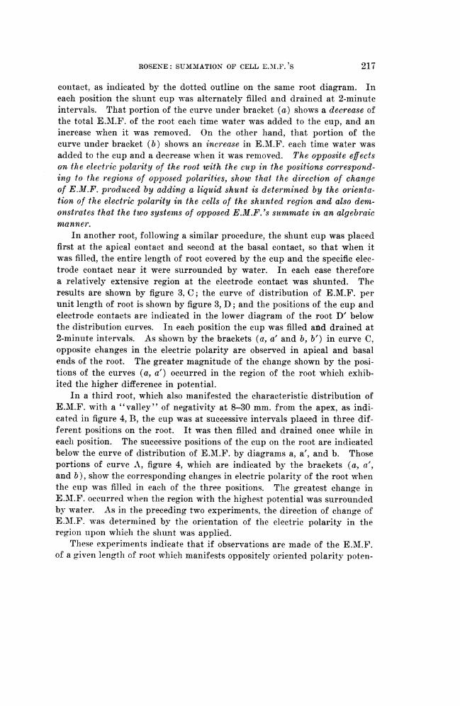
FIG. 3. Effect of placing a liquid shunt on different regions of opposed electricpolarities. Curves B and D show distribution of potential in two different roots. Upperroot (diagram B') below the distribution curves shows exact positions of electrode con-tacts (arrows) and two successive positions of shunt cup in experiments from whichcurves (a) and (b). in A were obtained. Lower root (diagraam D') is correspondingdiagram for curves in C. In A and C the portions of the curves indicated by the brack-ets (a, a') were obtained when the shunt cup was in the position indicated by the con-tinuous heavy outline of the cup on each root diagram; those portions indicated bybrackets (b, b') when it was in the position indicated by the interrupted outline of thecup. Heavy portions of the base line -of A and C show when the cup was filled withwater; intervals between, when it was empty.
216
ROSENE: SUMAIMATION OF CELL E.AI.F. 'S
contact, as indicated by the dotted outline on the same root diagram. Ineach position the shunt cup was alternately filled and drained at 2-minuteintervals. That portion of the curve under bracket (a) shows a decrease ofthe total E.M.F. of the root each time water was added to the cup, and anincrease when it was removed. On the other hand, that portion of thecurve under bracket (b) shows an increase in E.MA.F. each time water wasadded to the cup and a decrease when it was removed. The opposite effectson the electr ic polarity of the root with the cutp in the positions corr-espond-ing to the regionts of opposed polarities, show that the direction of changeof E.M.F. produced by adding a liquid shunt is determined by the orienta-tion of the electric polarity in the cells of the shutnted region and also demn-onstrates that the two systems of opposed E.M.F. 's summate in an algebraicmanner.
In another root, following a similar procedure, the shunt cup was placedfirst at the apical contact and second at the basal contact, so that when itwas filled, the entire length of root covered by the cup and the specific elee-trode contact near it were surrounded by water. In each case thereforea relatively extensive region at the electrode contact was shunted. Theresults are shown by figure 3, C; the curve of distribution of E.M.F. perunit length of root is shown by figure 3, D; and the positions of the cup andelectrode contacts are indicated in the lower diagram of the root D' belowthe distribution curves. In each position the cup was filled ankd drained at2-minute intervals. As shown by the brackets (a, a' and b, b') in curve C,opposite changes in the electric polarity are observed in apical and basalends of the root. The greater magnitude of the change shown by the posi-tions of the curves (a, a') occurred in the region of the root which exhib-ited the higher difference in potential.
In a third root, which also manifested the characteristic distribution ofE.M.F. with a "valley" of negativity at 8-30 mm. from the apex, as indi-cated in figure 4, B, the cup was at successive intervals placed in three dif-ferent positions on the root. It was then filled and drained once while ineach position. The successive positions of the cup on the root are indicatedbelow the curve of distribution of E.M.F. by diagrams a, a', and b. Thoseportions of curve A, figure 4, which are indicated by the brackets (a, a',and b), show the corresponding changes in electric polarity of the root wlhenthe cup was filled in each of the three positions. The greatest changre inE.AI.F. occurred when the region with the highest potential was surroundedby water. As in the preceding two experiments, the direction of change ofE.MN.F. was determined by the orientation of the electric polarity in theregion upon which the shunt was applied.
These experiments indicate that if observations are made of the E.M.F.of a given length of root which manifests oppositely oriented polarity poten-
217

PLANT PHYSIOLOGY
Tf' r - t aT ~~~~~~~~~~~a'
b
FIG. 4. Effect on electric potential, of addition and removal of a liquid shunt atthree different positions on the root with a curve of distribution of E.M.F. as shown inB. Diagrams a, a', and b below base line show successive and exact positions of shuntcup on same root. Arrows indicate positions of electrode contacts. The parts of thecurve above the brackets (a) and (a') and (b) in A indicate the change in E.M.F. pro-duced by adding and removing water from the shunt cup in the positions correspondingto a, a', and b of the root diagrams below.
tials, during an interval when the shunt cup filled with water is moved upor down the root, increase or decrease in E.M.F. would appear when thecup passed over a "hill" or "valley" of potential difference. In this waythe orientation as well as the relative magnitude of E.M.F.'s per unitlength could be determined.
Many such determinations on different roots were made, and the orien-tation and relative magnitude of E.M.F.'s per unit length was ascertainedin this manner. In each case results were checked by comparison with thecurve of distribution of E.M.F. per unit length obtained by moving thepositive electrode toward the negative electrode as described above. Whenthe empty cup or the cup filled with paraffin oil was similarly moved, nochanges in E.M.F. were observed.
These experiments show further that we are dealing with a system orsystems of E.M.F.'s, some of which at least have their origin in polar cellsarranged in series. This point will be clear if the reader will refer to the
218

ROSENE: SUMMATION OF CELL E.Ml.F. 'S
discussion and diagrams of cells in series and in parallel in LUND'S paper(4) on the theory of cell correlation. In diagram I of figure 2, pages 285,LUND gives a simple hypothetical system of four cells, A, B, C, and D, ar-ranged in series in which A is from the region of highest positive potential,B from a region just proximal to A, C from an isoelectric region, and Dfrom a region of oppositely oriented polarity. When connected in series asillustrated, the total E.M.F. of the system would be equal to the algebraicsum of the E.M.F.'s of the cells between the contacts as represented bycircuit 4 in the diagram (fig. 2, I, LUND 4). If, in such a system, a de-crease is produced in the IR drop of cells A or B or both, the total E.M.F.of the system would necessarily fall; and if such a decrease is sufficientlygreat in magnitude the polarity of the system would be reversed since itwould then be determined by the polarity of cell D. This is the explana-tion for the drop in potential shown in curves A and C, figure 3, and curveA in figure 4 when the conducting medium was placed around a region ofhigh positive potential. If, on the other hand, a decrease is produced inthe IR drop of cell D, the E.M.F. of which is opposing the P.D.'s of cellsA and B, an increase in the total E.M.F. of the system will appear, as shownby the rise in potential in curves A and C, figure 3, and curve A, figure 4,which occurred when the conducting medium was placed around a regionthat exhibited a negative polarity potential.
PROCEDURE 5
SHUNT CUP OUTSIDE OF THE ELECTRODE JACKET
Very little or no change in E.M.F. of the root is observed when wateris added to or removed from the shunt cup when placed outside of the elec-trode circuit. Figure 5, X and Y, shows the positions of the electrode con-tacts in two such experiments. The shunt cup in one experiment was filledwith water during the first half of the experiment and with paraffin oilduring the latter half. At 1-minute intervals the cup was alternately raisedand lowered, thus surrounding 1.5 mm. of the extreme tip with water whenraised. The position of the cup when over the tip is indicated by the inter-rupted outline in figure 5, X. The results are represented by curve A. Thestippled portions of the curve show the intervals during which the apexdipped into the water-filled cup and the portions indicated by diagonal linesgive the intervals during which the apex dipped into the oil-filled cup.Each time the water-filled cup was raised over the root, a small but definitedrop in E.M.F. occurred, and each time it was lowered a small increase inE.M.F. was observed. No such change in E.M.F. was noticed when the oil-filled cup was similarly raised and lowered. In both experiments the effectwas very small.
219

PLANT PHYSIOLOGY
0 2 4 A kiUS a2 6 0
10 S 10 IS 20UiNUTtS 0 S 10 15 20\FSNJE5
FIG. 5. Effect of tap-water shunt on E.M.F. of a given region when it is appliedto a region of the root outside of the electrode circuit. Insets X and Y are diagramsof two different roots which show exact position of the segments of the root covered bythe shunt cup, as indicated by the interrupted outline in X and the solid loutline of thecup in Y. Stippled areas on the base line of A and B show when the shunt cup is filledwith water, diagonal portions when it is filled with paraffin oil, and intervals betweenwhen the cup is empty.
In the other experiment the cup was placed in position around a regionof the root relatively basal, as illustrated by figure 5, Y. It was filled withwater during the intervals represented by the stippled portions of curve B,figure 5. Curve B indicates that no change in E.M.:F. is produced by add-ing and removing water from the cup under these conditions.
Both experiments showed that the electric polarity of the root was in afluctuating state manifesting rhythm. The small change in E.M.F. ob-served when the water-filled cup was raised and lowered indicates that partof the electric field at the apical electrode contact was included in the regioncovered by the cup when it was raised.
Experiments on frog nerve
The frog 's sciatic nerve was carefully isolated and a thread tied aroundthe proxrimal end by means of which the nerve was gently threaded throughthe openings of (a) the glass projection (contact) of the electrode connec-tion to the quadrants, (b) the bottom of the empty shunt cup, (c) the glassprojection (contact) of the grounded electrode cup, and finally fastened ina glass clamp which thus suspended the nerve in the moist electrode cham-ber. The electrode cups and glass projections were filled with frog Ringersolution. When both electrode contacts surrounded the .uninjured surfaceof the nerve no potential was exhibited, but when the nerve was cut at theelectrode contact (to quadrant) on the distal portion below the cup, an in-jury E.M.F. appeared. This E.M.F'. was not subject to change by addingand removing Ringer solution around the region surrounded by the cup,nor did any effect appear when paraffin oil replaced the Ringer solution.Although the procedures described above in the experiments on the onion
220

ROSENE: SUMMATION OF CELL E.M.F. 'S
root were repeated with different nerves, the presence of a liquid conductoraround the uninjured surface of the nerve between the electrode contactsfailed to produce an effect on the injury potential in any way comparableto that which was observed on the maintained E.M.F. of the polar cells inthe root tissue. Evidently the systems of E.M.F. are fundamentally dif-ferent in one or more respects; in the root tissue there is a system ofcellular E.M.F.'s arranged in series (and probably in parallel also) suchthat the addition of a liquid conductor around cells between and not at thecontacts will alter the total E.M.F. of that system, whereas in the injurednerve the system is closed and the addition of a liquid conductor betweenthe contacts does not alter the E.M.F. In the latter case, the origins of theP.D.'s are probably limited to the electrode contacts. In the root electri-cally polar tissue is present, the cells of which are the seats of individualE.M.F. 's that summate algebraically to give the E.M.F. of that system.
Conclusions
The preceding experiments show that when tap water is placed arounda region of the onion root between the electrode contacts the E.M.F. of theroot is altered, but when paraffin oil is similarly placed around a region ofthe root no change in E.M.F. is observed. This fact indicates that when aliquid which contains electrolytes surrounds a region of the root the outputof electric energy by the root is altered. The effect on individual cellE.M.F.'s is summated and expressed in the change of the electric polarityof the whole. A liquid shunt around the region of the root which exhibitsa positively oriented unidirectional polarity diminishes the electric polarityof the whole, while a liquid shunt around the region which exhibits an oppo-sitely oriented unidirectional polarity increases the electric polarity of thewhole. This fact furnishes conclusive evidence that the total observedE.M.F. of the onion root is the algebraic sum of the definitely orientedE.M.F.'s of individual cells.
The fact that the E.M.F. between the cut end and the longitudinal sur-face of the frog sciatic nerve was not altered by following the procedureused in the experiments on the root shows that the observed effect producedby adding a liquid shunt to the root is uniquely characteristic of the systemof continuously maintained bioelectric potentials, distinctive of the rootcells.
The fact that the potential difference of the root may be increased ordecreased by a liquid shunt indicates that the electric circuit system of theroot is not a closed system. In its natural environment the root is exposedto soil or other solutions which contain electrolytes. Bioelectric currentsflow outward into the surrounding medium from regions of high electricpositivity in the root and currents flow inward from the surroundings to
221

PLANT PHYSIOLOGY
regions which exhibit relatively low positivity or negativity. Accordingly,the observed phenomena are obviously significant in relation to the prob-lems of (1) transport of ions, (2) absorption of water and solutes by theroot, (3) transpiration, and (4) growth.
Energy changes are involved in the process of absorption, and many in-vestigators have shown that permeability and osmotic relations alone areinadequate to explain the phenomena of absorption in the root (1, 3, 9, 14).The electric energy produced by the oxidative metabolism of the cells (5,13) is continuously available for work and may be utilized by the root inthe processes of absorption and transport. It has been shown that absorp-tion of water and ions by the root is directly correlated with oxidation (10,2, 7), and it has been demonstrated for the first time that the electricpotentials of the root and oxygen tension are quantitatively interdependent(6, 13). A consideration of the fact that the electric circuit of the root isnot a closed system, and the above mentioned relations (i.e., (a) of bioelec-tric currents to oxidation and (b) of absorption to oxidation) indicatesthat these are linked phenomena.
The fact that electric energy is available for the transport of ions, andthe additional fact that the E.M.F. of the root is modified only when anelectrolytic solution comes in contact with the root, indicate that the avail-able output of electric energy by the root is related to the conductivity ofthe solutions in which the roots grow. Root growth is dependent upon iontransport and upon the absorption of water and solutes. It may possiblydiffer in solutions of low and high electric conductivity.
A detailed discussion of the experimental results in relation to thephenomena mentioned above will be omitted, since the purpose of thisreport is to show that the magnitude and orientation of cellular E.M.F.'sis modified by an electrolytic solution around the root and that the electriccircuit of the root is not a closed system, but attention is called to the factthat the study of electric behavior of the root establishes a precise andintelligible approach to the problems of (1) transport of ions, (2) absorp-tion of water and solutes, (3) transpiration, and (4) growth.
Summary1. The electric polarity of a given region of the root tip (Allium cepa)
is decreased or increased when an electrolytic solution such as tap water(liquid shunt) surrounds a segment of that region.
2. The magnitude of change in electric polarity is directly related tothe length of the liquid shunt, and the direction of change is determinedby the orientation of the polarity potential in the segment to which theshunt is applied.
3. The level of E.M.F. manifested before the liquid shunt is applied isreestablished when the shunt is removed.
222

ROSENE: SUMMATION OF CELL E.M.F. 'S
4. The observed changes in E.M.F. produced by the addition of a liquidshunt to the root are distinguished from the rhythmic fluctuations inE.M.F., produced by causes of internal origin, by the abrupt change inE.M.F. which occurs when the shunt is added.
5. The observed changes in E.M.F. are determined by the presence ofions in the applied solution. No change in E.M.F. of a given region of theroot is observed when a non-conducting liquid is applied to a segment atthat region.
6. The results indicate that the system of continuously maintainedE.M.F.'s present in the root involves cells arranged in series so that theirpolar axes coincide.
7. When the liquid shunt is applied to a region outside of the electrodecircuit no change in E.M.F. is produced.
8. There is an absence of effect on the injury E.M.F. of frog sciaticnerve following the same procedure used in the experiments on the root.The observed change in E.M.F. of the root, produced by the addition of aliquid shunt, is uniquely characteristic of the system of maintained cellularE.M.F.'s present in the root.
9. The observations furnish direct evidence that the principle of alge-braic summation of E.M.F.'s in polar cell systems applies to the electricpolarity of the onion root.
The writer wishes to express gratitude to Prof. E. J. LUND for valu-able suggestions and criticisms. The investigation was aided by a grantfrom the research fund of the Department of Zoology, University of Texas.
UNIVERSITY OF' TEXASAUSTIN, TEXAS
LITERATURE CITED1. BREAZEALE, J. E. Nutrition of plants as an electrical phenomenon.
Jour. Agr. Res. 24: 40-54. 1923.2. HENDERSON, LETA. Relation between root respiration and absorption.
Plant Physiol. 9: 283-300. 1934.3. HOAGLAND, D. R. Absorption of ions by plants. Soil Sci. 16: 235-
246. 1923.4. LUND, E. J. Relation between bioelectric currents and cell respiration
II. Theory of cell correlation. Jour. Exp. Zool. 51: 265-290.5. . The unequal effect of 02 concentration on the velocity
of oxidation in loci of different electric potential and glutathionecontent. Protoplasma 13: 236-258. 1931.
6. , and KENYON, W. A. I. Electric correlation potentialsin growing root tips. Jour. Exp. Zool. 48: 333-357. 1927.
223

PLANT PHYSIOLOGY
7. LUNDERARDH, H., and BURSTROM, H. Atmung und Ionenaufnahme.Planta 18: 683-699. 1933.
8. MARSH, G. IV. The origin of electric polarity in the onion root.Jour. Exp. Zool. 51: 309-325. 1928.
9. MAXMov, N. A. The plant in relation to water. Macmillan Co., NewYork. 1929.
10. MMiER, EDWIN C. Plant physiology. McGraw-Hill Book Co., NewYork. 1931.
11. NEWTON, J. D. Measurements of CO2 evolved from the roots of vari-ous crop plants. Sci. Agr. 4: 268-274. 1924.
12. . The relation of salt concentration of the culture solu-tion to transpiration and root respiration. Sci. Agr. 5: 318-320.1925.
13. ROSENE, H. F., and LUND, E. J. Linkage between output of electricenergy by polar tissues and cell oxidation. Plant Physiol. 10:27-47. 1935.
14. TUPPER-CAREY, R. M., and PRIESTLEY, J. H. The composition of thecell wall of the apical meristem and root. Proc. Roy. Soc. London.95 B: 109-131. 1922.
224