propagating contact lines and dynamic fracture mechanics · propagating contact lines and dynamic...
TRANSCRIPT
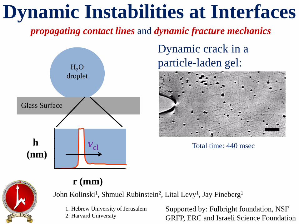
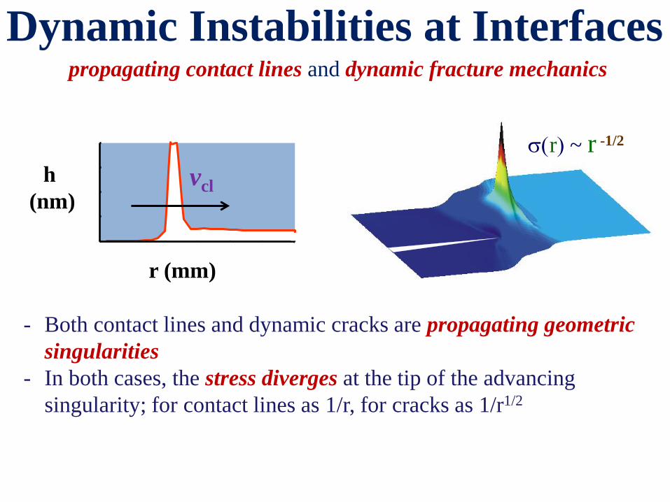
propagating contact lines and dynamic fracture mechanics
Dynamic Instabilities at Interfaces
Total time: 440 msec
John Kolinski1, Shmuel Rubinstein2, Lital Levy1, Jay Fineberg1
H2O
droplet
Glass Surface
1. Hebrew University of Jerusalem
2. Harvard University
Supported by: Fulbright foundation, NSF
GRFP, ERC and Israeli Science Foundation
r (mm)
h
(nm) vcl
Dynamic crack in a
particle-laden gel:
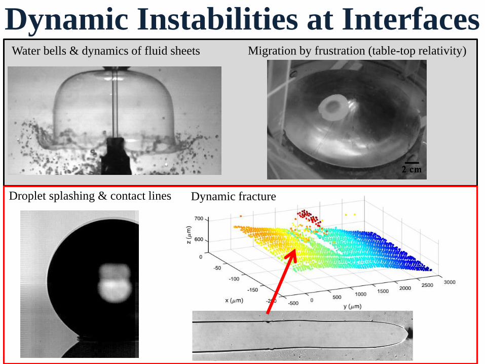
Dynamic Instabilities at Interfaces Water bells & dynamics of fluid sheets Migration by frustration (table-top relativity)
Droplet splashing & contact lines Dynamic fracture
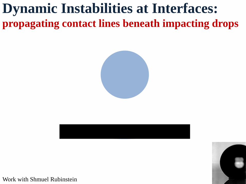
Dynamic Instabilities at Interfaces: propagating contact lines beneath impacting drops
Work with Shmuel Rubinstein
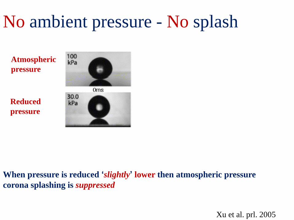
When pressure is reduced ‘slightly’ lower then atmospheric pressure
corona splashing is suppressed
Xu et al. prl. 2005
No ambient pressure - No splash
Atmospheric
pressure
Reduced
pressure
4
-150 -100 -50 0 100 150 50
8
X (mm)
y(m
m)
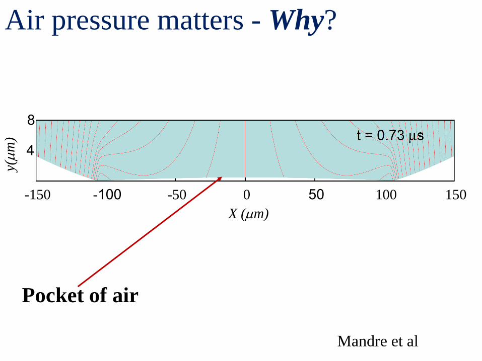
Mandre et al
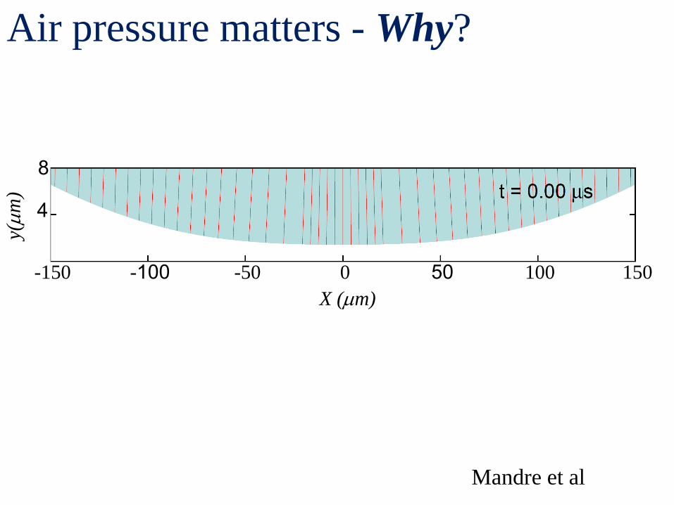
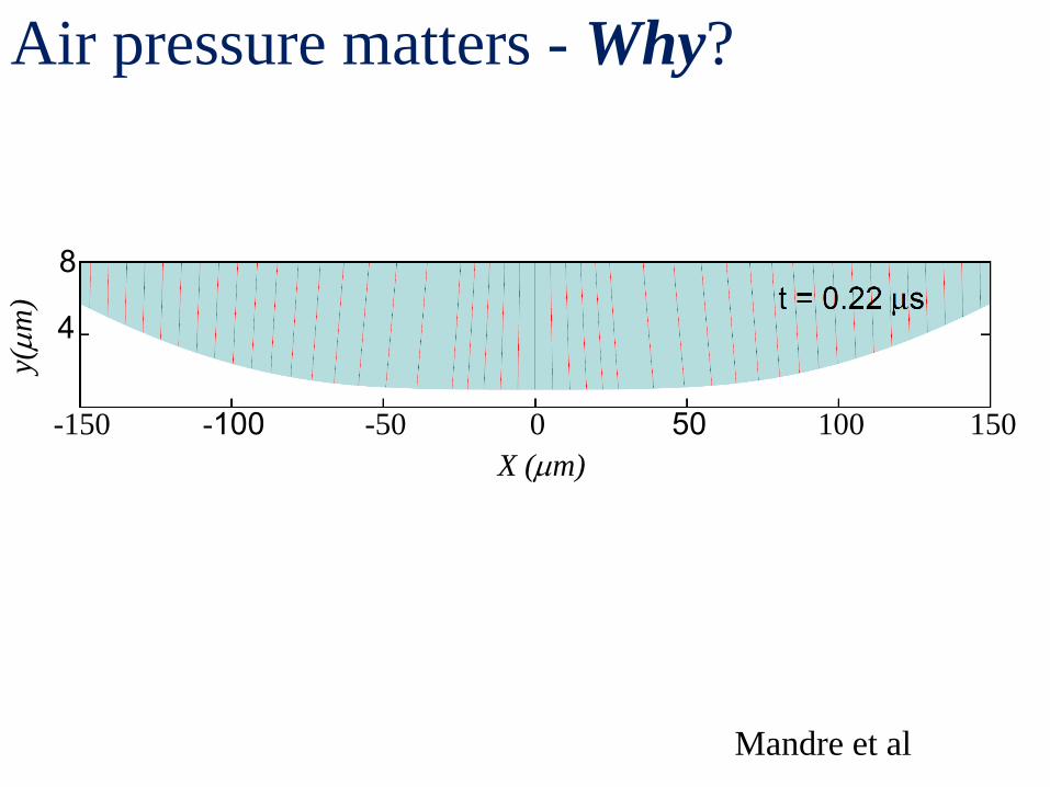
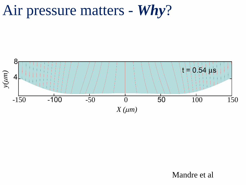
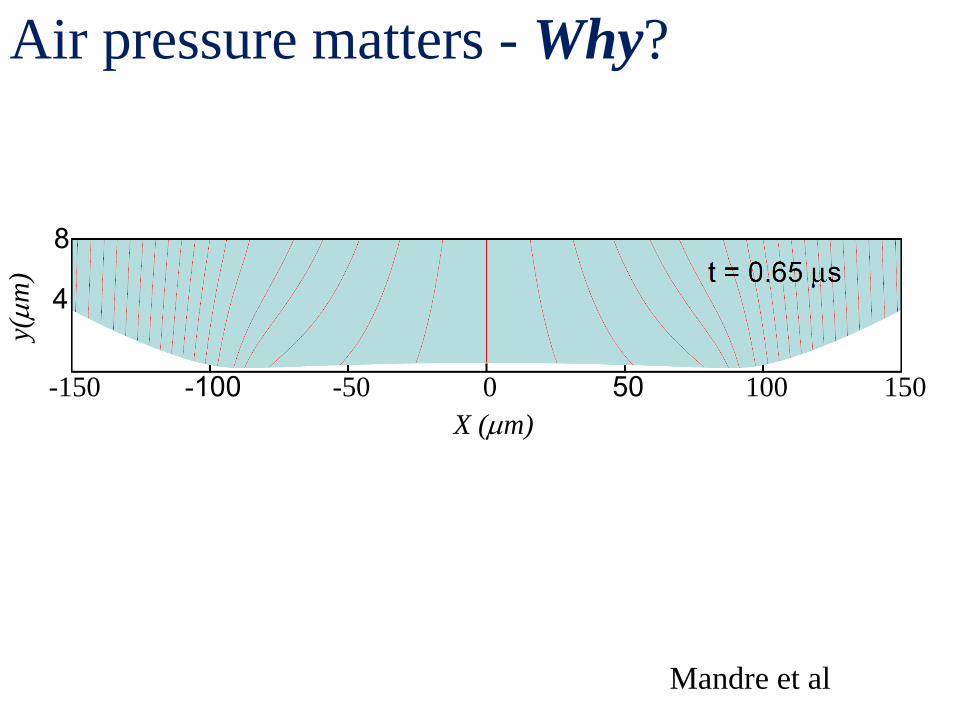
Air pressure matters - Why?
4
-150 -100 -50 0 100 150 50
8
X (mm)
y(m
m)
Mandre et al
Air pressure matters - Why?
4
-150 -100 -50 0 100 150 50
8
X (mm)
y(m
m)
Mandre et al
Air pressure matters - Why?
4
-150 -100 -50 0 100 150 50
8
X (mm)
y(m
m)
Mandre et al
Air pressure matters - Why?
4
-150 -100 -50 0 100 150 50
8
X (mm)
y(m
m)
Mandre et al
Pocket of air
Air pressure matters - Why?
4
-150 -100 -50 0 100 150 50
8
X (mm)
y(m
m)
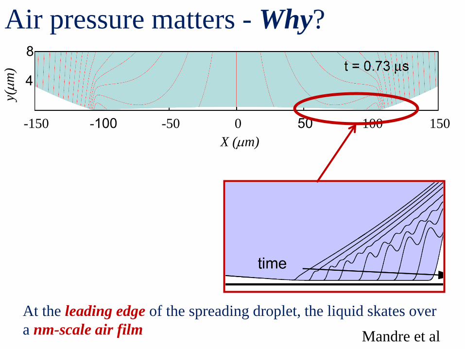
Air pressure matters - Why?
At the leading edge of the spreading droplet, the liquid skates over
a nm-scale air film Mandre et al
4
-150 -100 -50 0 100 150 50
8
X (mm)
y(m
m)
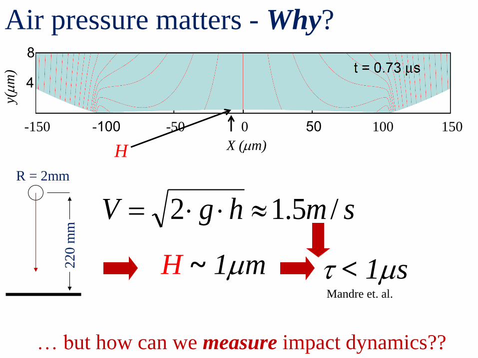
R = 2mm
220 m
m
H ~ 1mm Mandre et. al.
t < 1ms
smhgV /5.12
Air pressure matters - Why?
… but how can we measure impact dynamics??
H
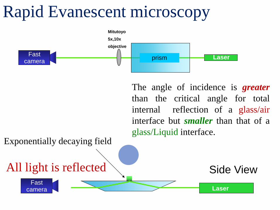
Fast camera
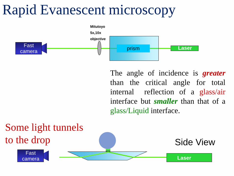
Laser prism
Mitutoyo
5x,10x
objective
Laser
Side View
Rapid Evanescent microscopy
Exponentially decaying field
All light is reflected
The angle of incidence is greater
than the critical angle for total
internal reflection of a glass/air
interface but smaller than that of a
glass/Liquid interface.
Fast camera
Fast camera
Laser prism
Mitutoyo
5x,10x
objective
Laser
Side View
Rapid Evanescent microscopy
The angle of incidence is greater
than the critical angle for total
internal reflection of a glass/air
interface but smaller than that of a
glass/Liquid interface.
Fast camera
Some light tunnels
to the drop
Laser
Side View
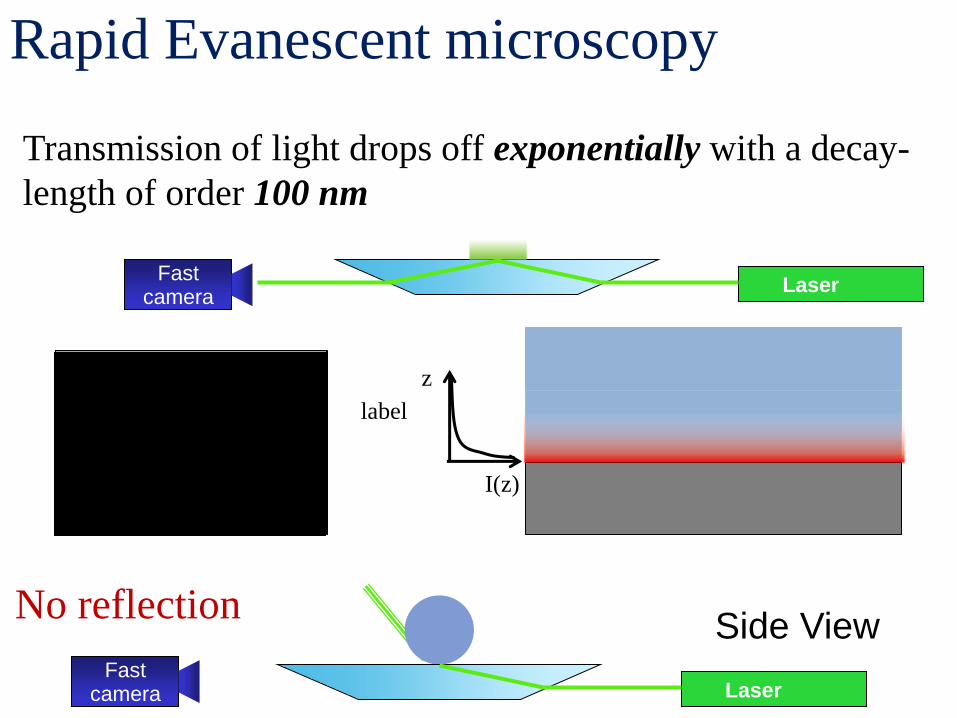
Rapid Evanescent microscopy
No reflection
Fast camera
Transmission of light drops off exponentially with a decay-
length of order 100 nm
Laser
I(z)
z
Fast camera
label
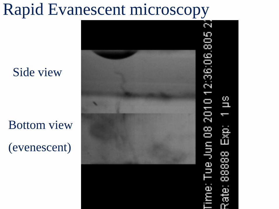
Side view
Bottom view
(evenescent)
Rapid Evanescent microscopy
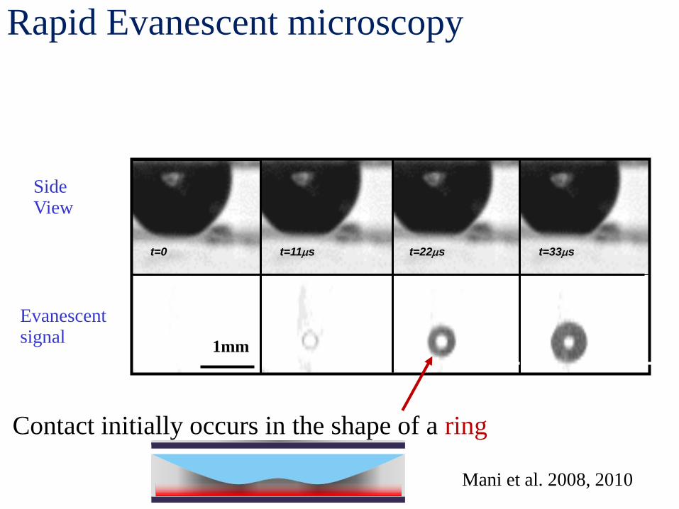
t=11ms t=22ms t=0 t=33ms
Rapid Evanescent microscopy
Side View
Evanescent signal 1mm 1mm
Contact initially occurs in the shape of a ring
Mani et al. 2008, 2010
Dynamics prior to contact On droplet splashing: Kolinski et. al., PRL 2012
On the lift-off transition: Kolinski et. al., PRL 2014
On droplet rebound: Kolinski et. al., EPL 2014
On contact growth: Kolinski and Rubinstein, under review - Dynamics after contact
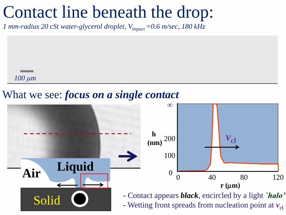
Contact line beneath the drop: 1 mm-radius 20 cSt water-glycerol droplet, Vimpact =0.6 m/sec, 180 kHz
100 mm
What we see: focus on a single contact
Air Liquid
Solid
0 40 80 120 0
100
200
∞
r (mm)
h
(nm) vcl
- Contact appears black, encircled by a light `halo’
- Wetting front spreads from nucleation point at vcl
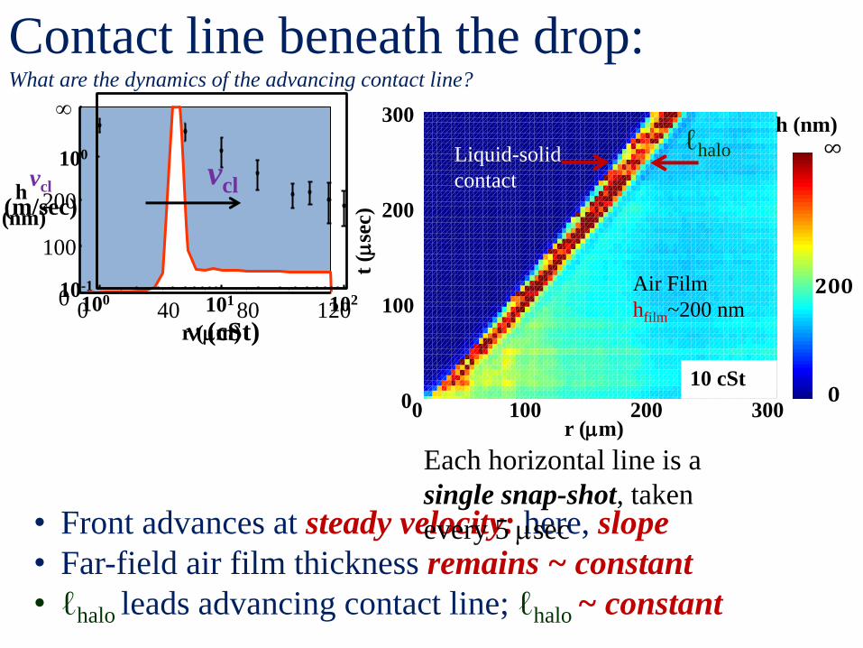
Contact line beneath the drop: What are the dynamics of the advancing contact line?
• Front advances at steady velocity: here, slope
• Far-field air film thickness remains ~ constant
• ℓhalo leads advancing contact line; ℓhalo ~ constant
0 300 200 100
∞
𝟎
𝟐𝟎𝟎
10 cSt 0
100
200
300
t (m
sec)
r (mm)
h (nm)
Air Film
hfilm~200 nm
Liquid-solid
contact
ℓhalo
0 40 80 120 0
100
200
∞
r (mm)
h
(nm)
vcl
102
100
10-1
100 101
vcl
(m/sec)
n (cSt)
Each horizontal line is a
single snap-shot, taken
every 5 msec
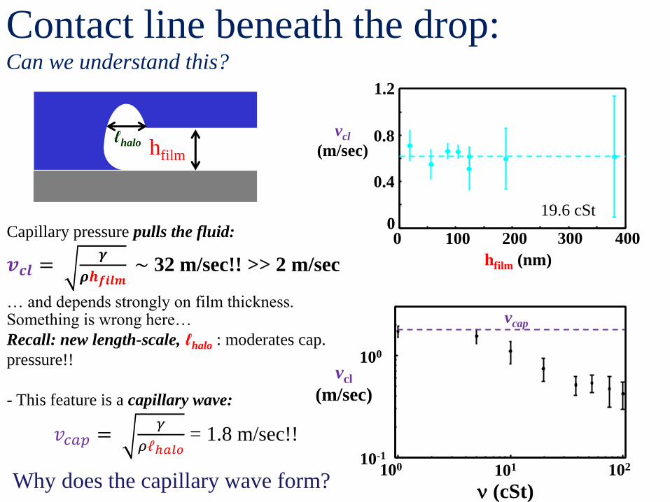
Contact line beneath the drop: Can we understand this?
0 100 200 0
1.2
hfilm (nm)
vcl
(m/sec) 0.8
0.4
300 400
19.6 cSt
Something is wrong here…
Recall: new length-scale, ℓhalo : moderates cap.
pressure!!
- This feature is a capillary wave:
𝑣𝑐𝑎𝑝 = 𝛾
𝜌ℓℎ𝑎𝑙𝑜 = 1.8 m/sec!!
hfilm
Capillary pressure pulls the fluid:
𝒗𝒄𝒍 = 𝜸
𝝆𝒉𝒇𝒊𝒍𝒎 ~ 32 m/sec!! >> 2 m/sec
… and depends strongly on film thickness.
102
100
10-1
100 101
vcl
(m/sec)
n (cSt)
vcap
Why does the capillary wave form?
ℓhalo
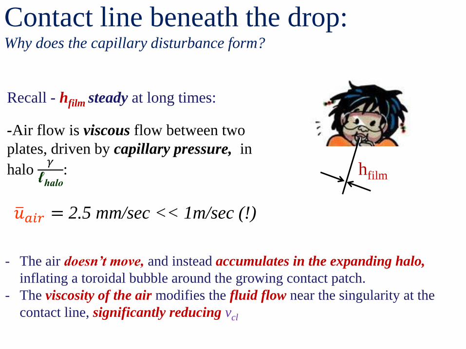
Contact line beneath the drop: Why does the capillary disturbance form?
hfilm
Recall - hfilm steady at long times:
-Air flow is viscous flow between two
plates, driven by capillary pressure, in
halo 𝛾
ℓhalo
:
𝑢 𝑎𝑖𝑟 = 2.5 mm/sec << 1m/sec (!)
- The air doesn’t move, and instead accumulates in the expanding halo,
inflating a toroidal bubble around the growing contact patch.
- The viscosity of the air modifies the fluid flow near the singularity at the
contact line, significantly reducing vcl
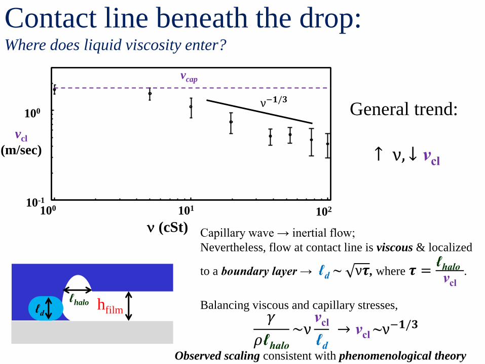
Contact line beneath the drop: Where does liquid viscosity enter?
General trend:
↑ ν, ↓ vcl
hfilm
Capillary wave → inertial flow;
Nevertheless, flow at contact line is viscous & localized
to a boundary layer → ℓd ~ ν𝝉, where 𝝉 =ℓhalo vcl
.
Balancing viscous and capillary stresses, 𝛾
𝜌ℓhalo
~νvcl
ℓd
→ vcl ~ν−𝟏/𝟑
Observed scaling consistent with phenomenological theory
102
100
10-1
100 101
vcl
(m/sec)
n (cSt)
vcap
ν−𝟏/𝟑
ℓhalo ℓd
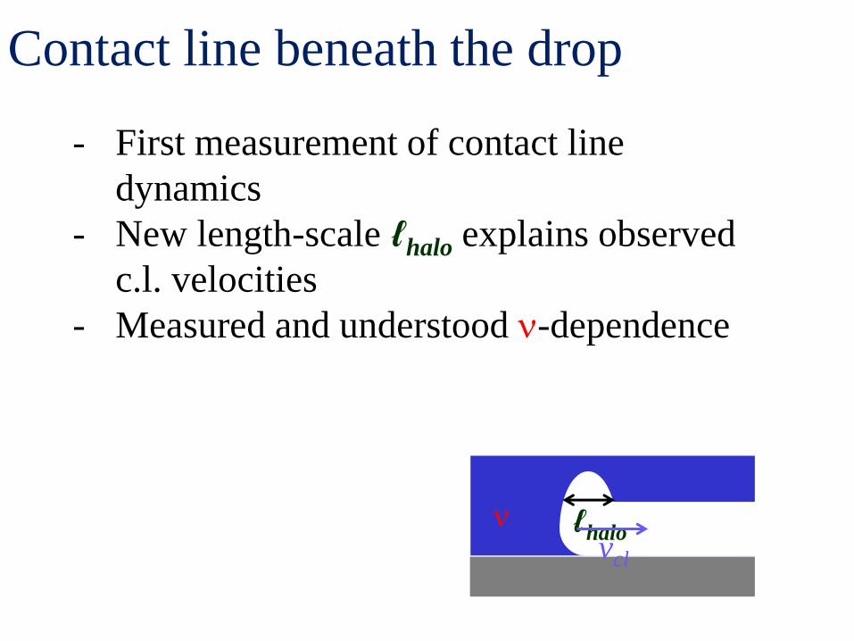
Contact line beneath the drop
- First measurement of contact line
dynamics
- New length-scale ℓhalo explains observed
c.l. velocities
- Measured and understood n-dependence
ℓhalo vcl
n
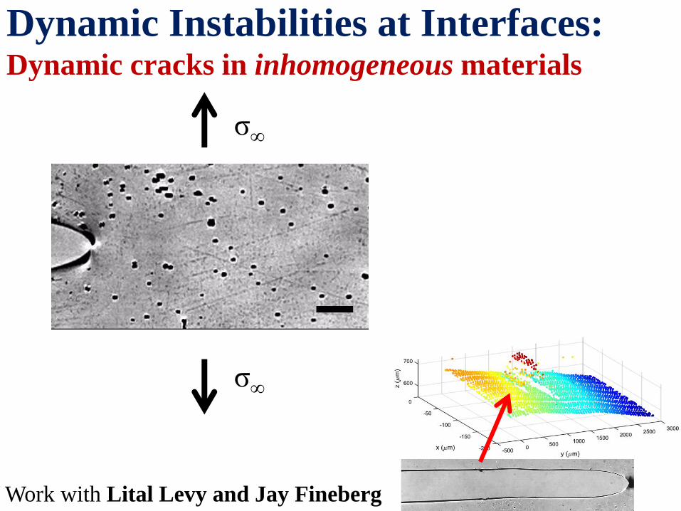
Dynamic Instabilities at Interfaces: Dynamic cracks in inhomogeneous materials
Work with Lital Levy and Jay Fineberg
σ∞
σ∞
CR (m/s) Poisson
ratio
Young’s
Modulus
(kPa)
Material
5-14 0.5 100-1000 Gel X% acrylamide
Y% bis-acrylamide
930 0.35 3,900,000
PMMA
3340 0.22 70,000,000 Soda-Lime glass
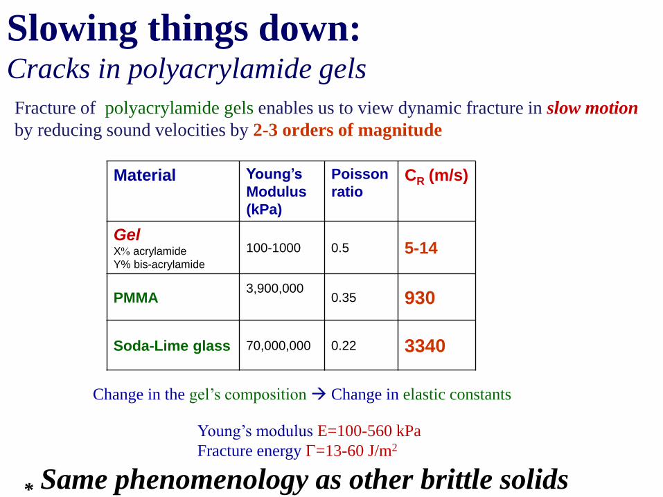
Fracture of polyacrylamide gels enables us to view dynamic fracture in slow motion
by reducing sound velocities by 2-3 orders of magnitude
Change in the gel’s composition Change in elastic constants
Young’s modulus E=100-560 kPa
Fracture energy G=13-60 J/m2
Slowing things down: Cracks in polyacrylamide gels
* Same phenomenology as other brittle solids
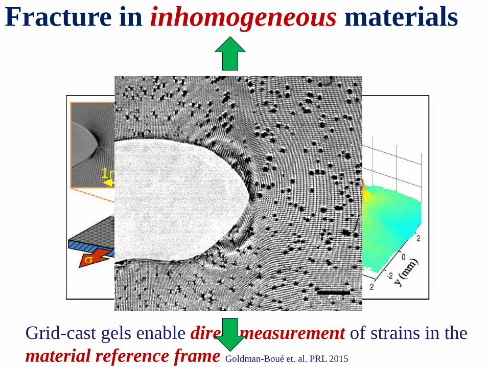
Fracture in inhomogeneous materials
Grid-cast gels enable direct measurement of strains in the
material reference frame Goldman-Boué et. al. PRL 2015
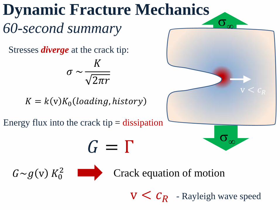
Dynamic Fracture Mechanics 60-second summary
Stresses diverge at the crack tip:
s∞
s∞
𝜎 ~𝐾
2𝜋𝑟
v < 𝑐𝑅
𝐺 = Γ
Energy flux into the crack tip = dissipation
𝐺~𝑔 v 𝐾02
𝐾 = 𝑘 v 𝐾0 𝑙𝑜𝑎𝑑𝑖𝑛𝑔, ℎ𝑖𝑠𝑡𝑜𝑟𝑦
Crack equation of motion
v < 𝑐𝑅 - Rayleigh wave speed
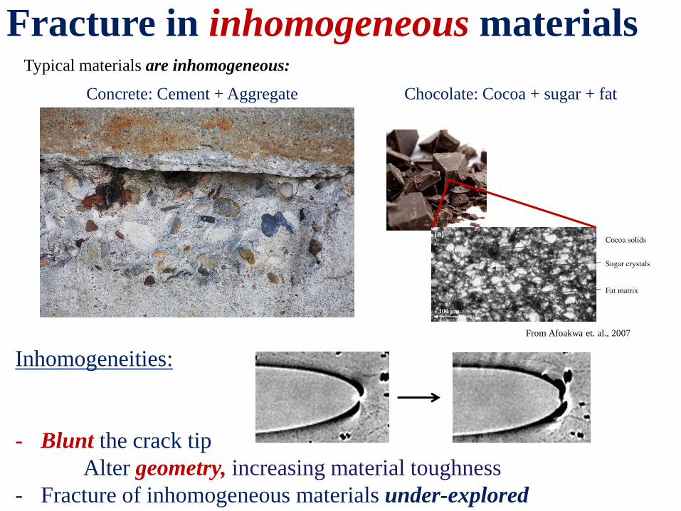
Fracture in inhomogeneous materials Typical materials are inhomogeneous:
Concrete: Cement + Aggregate Chocolate: Cocoa + sugar + fat
From Afoakwa et. al., 2007
Inhomogeneities:
- Blunt the crack tip
Alter geometry, increasing material toughness
- Fracture of inhomogeneous materials under-explored
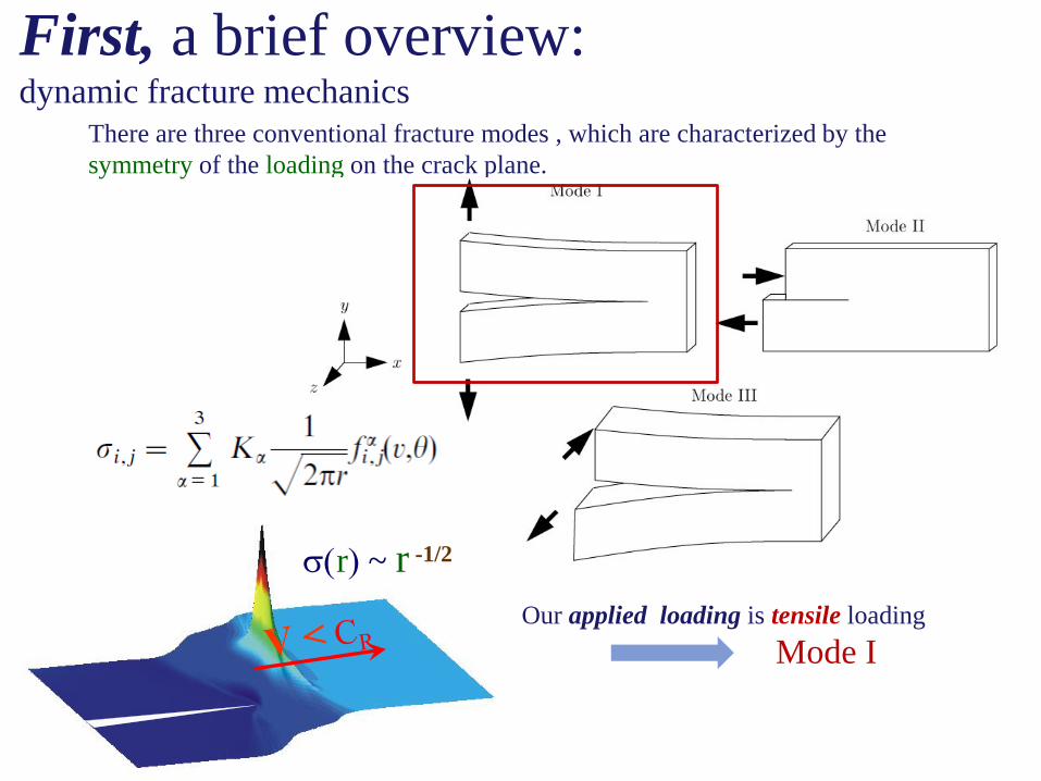
First, a brief overview: dynamic fracture mechanics
There are three conventional fracture modes , which are characterized by the
symmetry of the loading on the crack plane.
Our applied loading is tensile loading
Mode I
s(r) ~ r -1/2
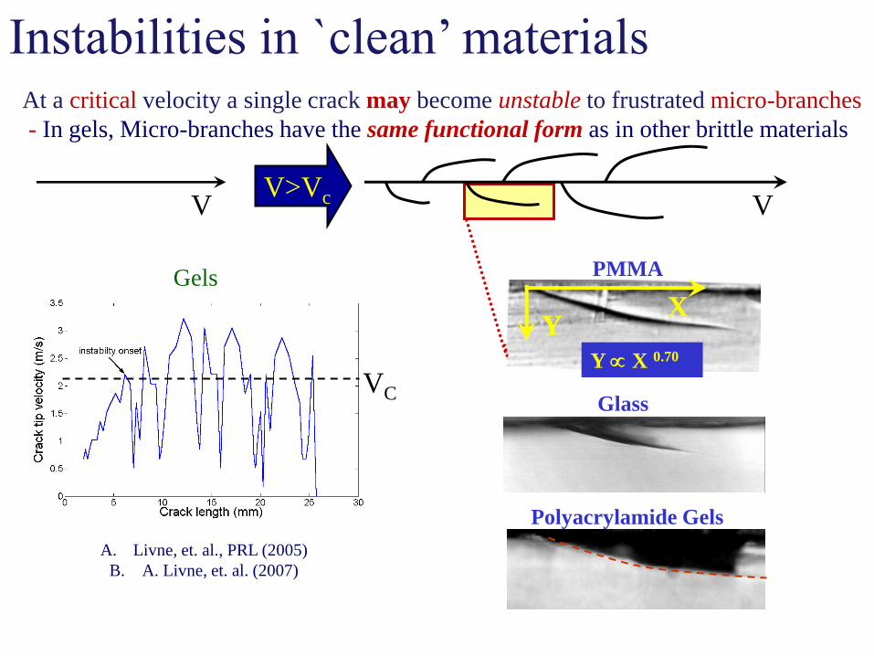
VC
Gels
A. Livne, et. al., PRL (2005)
B. A. Livne, et. al. (2007)
At a critical velocity a single crack may become unstable to frustrated micro-branches
- In gels, Micro-branches have the same functional form as in other brittle materials
Glass
PMMA
X Y
Polyacrylamide Gels
Y X 0.70
Instabilities in `clean’ materials
V V>Vc V
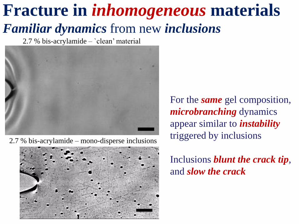
Fracture in inhomogeneous materials Familiar dynamics from new inclusions
For the same gel composition,
microbranching dynamics
appear similar to instability
triggered by inclusions
Inclusions blunt the crack tip,
and slow the crack
2.7 % bis-acrylamide – `clean’ material
2.7 % bis-acrylamide – mono-disperse inclusions
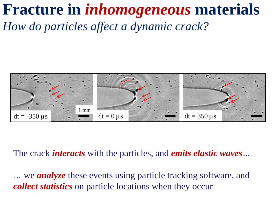
Fracture in inhomogeneous materials How do particles affect a dynamic crack?
1 mm
dt = -350 ms dt = 0 ms dt = 350 ms
The crack interacts with the particles, and emits elastic waves…
… we analyze these events using particle tracking software, and
collect statistics on particle locations when they occur
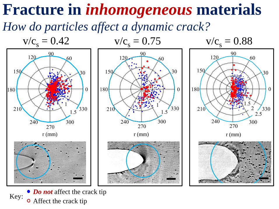
Fracture in inhomogeneous materials How do particles affect a dynamic crack?
Key: Affect the crack tip
Do not affect the crack tip
1
1.5
30
210
60
240
90
270
120
300
150
330
180 0
r (mm)
v/cs = 0.42
1
1.5
30
210
60
240
90
270
120
300
150
330
180 0
r (mm)
v/cs = 0.75
2 2.5
30
210
60
240
90 120
300
150
330
180 0
270
1.5
r (mm)
v/cs = 0.88
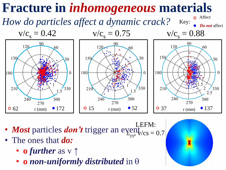
Fracture in inhomogeneous materials How do particles affect a dynamic crack? Key:
Affect
Do not affect
• Most particles don’t trigger an event
• The ones that do:
• o further as v ↑
• o non-uniformly distributed in
1
1.5
30
210
60
240
90
270
120
300
150
330
180 0
r (mm)
v/cs = 0.42
1
1.5
30
210
60
240
90
270
120
300
150
330
180 0
r (mm)
v/cs = 0.75
2 2.5
30
210
60
240
90 120
300
150
330
180 0
270
1.5
r (mm)
v/cs = 0.88
LEFM:
eyy, v/cs = 0.7
62 172 15 52 37 137
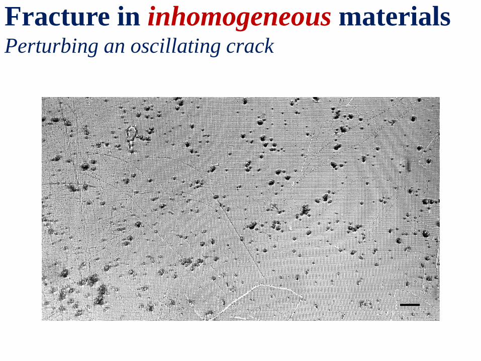
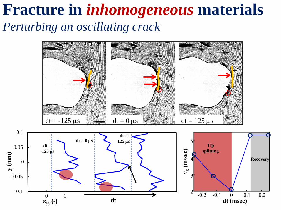
Fracture in inhomogeneous materials Perturbing an oscillating crack
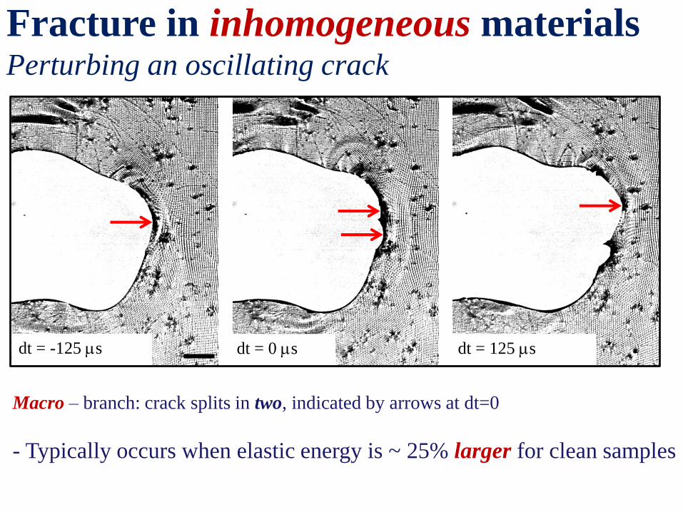
Fracture in inhomogeneous materials Perturbing an oscillating crack
dt = -125 ms dt = 0 ms dt = 125 ms
Macro – branch: crack splits in two, indicated by arrows at dt=0
- Typically occurs when elastic energy is ~ 25% larger for clean samples
dt = -125 ms dt = 0 ms dt = 125 ms
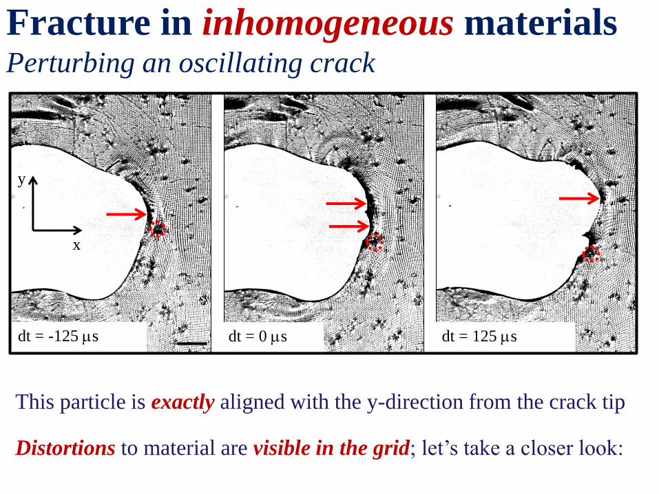
Fracture in inhomogeneous materials Perturbing an oscillating crack
This particle is exactly aligned with the y-direction from the crack tip
Distortions to material are visible in the grid; let’s take a closer look:
x
y
Fracture in inhomogeneous materials Perturbing an oscillating crack
dt = -125 ms dt = 0 ms dt = 125 ms
0 1 -0.1
-0.05
0
0.05
0.1
eyy (-)
y (
mm
)
dt =
-125 ms
dt
dt = 0 ms
dt =
125 ms
0 -0.2 -0.1 0.1 0.2 2
3
4
5
dt (msec)
vx (
m/s
ec)
Tip
splitting
Recovery
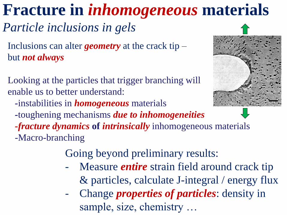
Fracture in inhomogeneous materials Particle inclusions in gels
Inclusions can alter geometry at the crack tip –
but not always
Looking at the particles that trigger branching will
enable us to better understand:
-instabilities in homogeneous materials
-toughening mechanisms due to inhomogeneities
-fracture dynamics of intrinsically inhomogeneous materials
-Macro-branching
Going beyond preliminary results:
- Measure entire strain field around crack tip
& particles, calculate J-integral / energy flux
- Change properties of particles: density in
sample, size, chemistry …
propagating contact lines and dynamic fracture mechanics
Dynamic Instabilities at Interfaces
r (mm)
h
(nm) vcl
s(r) ~ r -1/2
- Both contact lines and dynamic cracks are propagating geometric
singularities
- In both cases, the stress diverges at the tip of the advancing
singularity; for contact lines as 1/r, for cracks as 1/r1/2
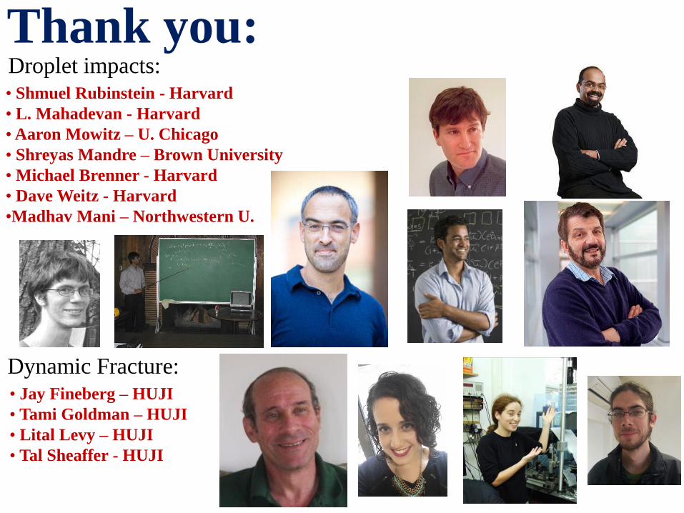
Thank you: • Shmuel Rubinstein - Harvard
• L. Mahadevan - Harvard
• Aaron Mowitz – U. Chicago
• Shreyas Mandre – Brown University
• Michael Brenner - Harvard
• Dave Weitz - Harvard
•Madhav Mani – Northwestern U.
Droplet impacts:
Dynamic Fracture: • Jay Fineberg – HUJI
• Tami Goldman – HUJI
• Lital Levy – HUJI
• Tal Sheaffer - HUJI
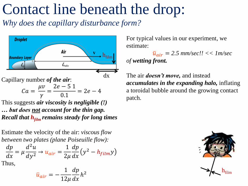
Contact line beneath the drop: Why does the capillary disturbance form?
hfilm
Capillary number of the air:
𝐶𝑎 = 𝜇𝑣
𝛾=
2𝑒 − 5 1
0.1= 2𝑒 − 4
This suggests air viscosity is negligible (!)
… but does not account for the thin gap.
Recall that hfilm remains steady for long times
Estimate the velocity of the air: viscous flow
between two plates (plane Poiseuille flow):
𝑑𝑝
𝑑𝑥= 𝜇
𝑑2𝑢
𝑑𝑦2 → 𝑢𝑎𝑖𝑟 =1
2𝜇
𝑑𝑝
𝑑𝑥𝑦2 − ℎ𝑓𝑖𝑙𝑚𝑦
Thus,
𝑢 𝑎𝑖𝑟 = −1
12𝜇
𝑑𝑝
𝑑𝑥ℎ2
hfilm
dx
For typical values in our experiment, we
estimate:
𝑢 𝑎𝑖𝑟 = 2.5 mm/sec!! << 1m/sec
of wetting front.
The air doesn’t move, and instead
accumulates in the expanding halo, inflating
a toroidal bubble around the growing contact
patch.
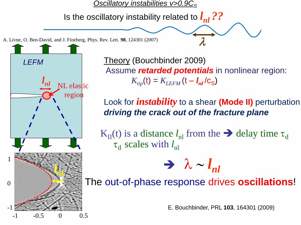
Oscillatory instabilities v>0.9CS
A. Livne, O. Ben-David, and J. Fineberg, Phys. Rev. Lett. 98, 124301 (2007)
E. Bouchbinder, PRL 103, 164301 (2009)
Is the oscillatory instability related to lnl ??
Theory (Bouchbinder 2009)
Assume retarded potentials in nonlinear region:
Ktip(t) = KLEFM (t – lnl /cS)
Look for instability to a shear (Mode II) perturbation
driving the crack out of the fracture plane
l
td scales with lnl KII(t) is a distance lnl from the delay time td
l ~ lnl
LEFM
lnl NL elastic
region
-1 -0.5 0 0.5
1
0
-1
The out-of-phase response drives oscillations!
lnl