properties of optical materials
TRANSCRIPT

PROPERTIES OF OPTICAL MATERIALS
PRESENTED BY:
HARIS KHAN MM-20SAAD ARIF MM-26OMAR SIDDIQUI MM-04MOIZ ULLAH BAIG MM-36DANIYAL AHMED MM-33
INTRODUCTION
• Optical materials are substances used to manipulate the flow of light
• Does every material has some optical properties?
• Optical property of a material is defined as its interaction with electro-magnetic radiation in the visible region.
• Visible light is one form of electromagnetic radiation with wavelengths ranging from 0.39 to 0.77 μm.
2

ELECTROMAGNETIC RADIATIONS
• Electromagnetic spectrum of radiation spans the wide range from γ-rays with wavelength as 10-12 m,
• Through x-rays, ultraviolet, visible, infrared, and finally radio waves with wavelengths as along as 105 m.
• Visible light is one form of electromagnetic radiation with wavelengths ranging from 0.39 to 0.77 μm.
• Light can be considered as having waves and consisting of particles called photons.
3

LIGHT INTERACTION WITH MATERIALS
• Interaction of photons with the electronic or crystal structure of a material leads to a number of phenomena.
1. The photons may give their energy to the material (absorption);
2. Photons give their energy, but photons of identical energy are immediately emitted by the material (reflection);
3. Photons may not interact with the material structure (transmission);
4. Or during transmission photons are changes in velocity (refraction).
• The efficiency of a specific material at each task is strongly wavelength dependent, thus a full understanding of the interaction between light and matter is vital.
4

CLASSIFICATION
• Materials are classified on the basis of their interaction with visible light in three categories:
• Materials that are capable of transmitting light with relatively little absorption and reflection are transparent.
• Those materials through which light is transmitted diffusely; that is, light is scattered within the interior, to the degree that objects are not clearly distinguishable when viewed through a specimen of the material are termed as translucent.
• Materials that are impervious to the transmission of visible light are termed opaque.
5

OPTICAL PROPERTIES OF METALS
• There are opaque to visible light due to crystallinity but are transparent to high frequency radiations (x-rays & gamma radiations)
• The incident radiation having frequencies within the visible range excites electrons into unoccupied energy states above the fermi energy
• All frequencies of visible light are absorbed by metals because of the continuously available empty electron states, which permit eletron transitions.
• Absorption take place in a very thin outer layer, usually less than 0.1 um; thus only metallic films thinner than 0.1 um are capable of transmitting visible light.
6
OPTICAL PROPERTIES OF NONMETALS
• Non-metallic materials consist of various energy band structures. Thus, all four optical phenomena are important.
• They may be transparent, translucent or opaque
• Examples are glass, plastics and semiconductors.
7
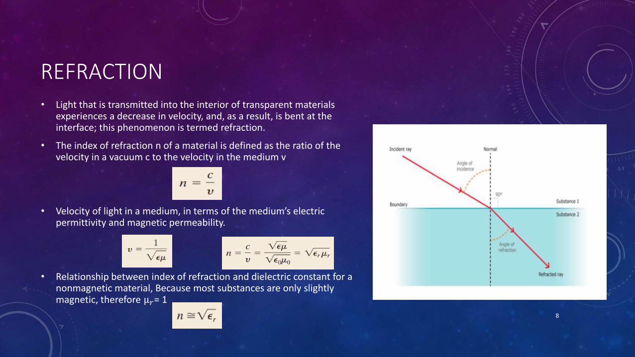
REFRACTION• Light that is transmitted into the interior of transparent materials
experiences a decrease in velocity, and, as a result, is bent at the interface; this phenomenon is termed refraction.
• The index of refraction n of a material is defined as the ratio of the velocity in a vacuum c to the velocity in the medium v
• Velocity of light in a medium, in terms of the medium’s electric permittivity and magnetic permeability.
• Relationship between index of refraction and dielectric constant for a nonmagnetic material, Because most substances are only slightly magnetic, therefore µ𝑟= 1
8

REFLECTION
• The reflectivity is defined as the fraction of the incident light that is reflected at the interface.
• If the material is in other material with refractive index
• Materials with a high index of refraction have a higher reflectivity than materials with a low index. Because the index of refraction varies with the wavelength of the photons, so does the reflectivity.
• In metals, the reflectivity is typically on the order of 0.90-0.95, whereas for glasses it is close to 0.05. The high reflectivity of metals is one reason that they are opaque. High reflectivity is desired in many applications including mirrors, coatings on glasses, etc.
9
ABSORPTION
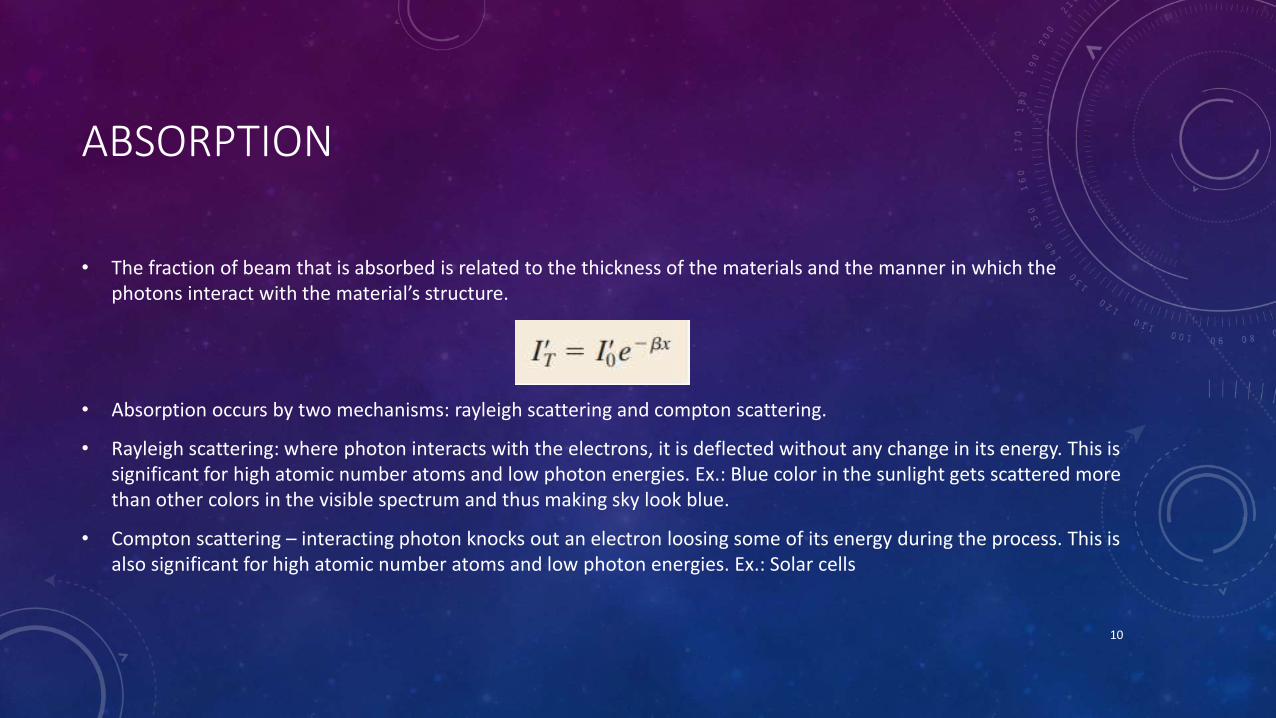
• The fraction of beam that is absorbed is related to the thickness of the materials and the manner in which the photons interact with the material’s structure.
• Absorption occurs by two mechanisms: rayleigh scattering and compton scattering.
• Rayleigh scattering: where photon interacts with the electrons, it is deflected without any change in its energy. This is significant for high atomic number atoms and low photon energies. Ex.: Blue color in the sunlight gets scattered more than other colors in the visible spectrum and thus making sky look blue.
• Compton scattering – interacting photon knocks out an electron loosing some of its energy during the process. This is also significant for high atomic number atoms and low photon energies. Ex.: Solar cells
10

TRANSMISSION
• The fraction of light beam that is not reflected or absorbed is transmitted through the material.
• This transmission depends on the losses that are incurred by absorption and reflection.
• For an incident beam of intensity 𝐼0 that impinges on the front surface of a specimen of thickness land absorption coefficient β, the transmitted intensity 𝐼𝑇 at the back face it is
11

COLOR, OPACITY & TRANSLUCENCY
• The color discerned is a result of the combination of wavelengths that are transmitted
• If absorption is uniform for all visible wavelengths, the material appears colorless
• Examples include high-purity inorganic glasses and high-purity and single-crystal diamonds and sapphire
• Opacity and translucency depends to a great degree on their internal reflectance and transmittance characteristics.
• Many materials that are intrinsically transparent may be made translucent or even opaque because of interior reflection and refraction
• For intrinsic polymers (without additives and impurities), the degree of translucency is influenced primarily by the extent of crystallinity.
Photograph showing the light transmittance of three aluminum oxide specimens. From left to right; single-crystal material (sapphire), which is transparent; a polycrystalline and fully dense (nonporous) material, which is translucent; and a polycrystalline material that contains approximately 5% porosity, which is opaque.
12

APPLICATIONS
• Light interacts with a material in many ways.
• Depending on the material, its crystal-/micro-structure, and also on the characteristics of incident light, there are many peculiar phenomena occurs, which are known as optical phenomena.
• These include:
1. Luminescence
2. Lasers
3. Photo-conductivity
4. Optical fibers
• All these find quite many applications in technology for every day life
13

LUMINESCENCE
• Materials are capable of absorbing energy and then reemitting visible light in a phenomenon called luminescence.
• Based on source for electron excitation, luminescence is three types: photo-luminescence, cathode-luminescence, and electro-luminescence.
• When light is reemitted in less than a second after excitation, the phenomenon is called fluorescence (photo-luminescence).
• For longer reemission times, the term phosphorescence is used (cathodic-luminescence).
• Electro-luminescence is the phenomenon whereby light is emitted as a result of electron–hole recombination events that are induced in a forward-biased diode.
• The device that experiences electroluminescence is the light-emitting diode (led). 14

PHOTO-LUMINESCENCE
• Photo-luminescence occurs in fluorescent lamps.
• Ultra-violet radiation from low-pressure mercury arc is converted to visible light by calcium halo-phosphate phosphor (ca10f2p6o24).
• In commercial lamps, about 20% of f - ions are replaced with Cl ions.
• Antimony, Sb3+ , ions provide a blue emission while manganese, Mn2+ , ions provide an orange-red emission band.
15

CATHODE-LUMINESCENCE
• Cathode-luminescence is produced by an energized cathode which generates a beam of high-energy bombarding electrons. Ex.: Applications of this include electron microscope; cathode-ray oscilloscope; color television screens.
• The modern televisions have very narrow, about 0.25 mm wide, vertical stripes of red-, green-, and blue- emitting phosphors deposited on the inner surface of the screens.
• Commercial phosphors for different colors are: red – yttrium oxy-sulfide (y2o2s) with 3% europium (eu); green – (zn,cd)s with a cu+ acceptor and al3+ donor; blue – zinc sulfide (zns) with ag+ acceptor and cl- donor.
Cathodoluminescence image of calcite crystals lining a fracture, showing very scale growth zoning highlighted by contrasting luminescence characteristics.
16

ELECTRO-LUMINESCENCE
• Electro-luminescence occurs in devices with p-n rectifying junctions which are stimulated by an externally applied voltage.
• When a forward biased voltage is applied across the device, electrons and holes recombine at the junction and emit photons in the visible range (mono-chromatic light i.e. singe color). These diodes are called light emitting diodes (LEDs).
• LEDs emit light of many colors, from red to violet, depending on the composition of the semiconductor material used. Ex.: GaAs, GaP, GaAlAs, and GaAsP are typical materials for LEDs.
17

LASER
• Laser is the acronym for light amplification by stimulated emission of radiation
• All the radiative electron transitions are spontaneous; that an electron falls from a high energy state to a lower one without any external provocation. These transition events occur independently of one another and at random times, producing radiation that is incoherent.
• With lasers, however, coherent light is generated by electron transitions initiated by an external stimulus
18

SCHEMATIC REPRESENTATION FOR A RUBY LASER
(a) The chromium ions before excitation.
(b) Electrons in some chromium ions are excited into higher energy states by the xenon light flash.
(c) Emission from metastable electron states is initiated or stimulated by photons that are spontaneously emitted.
(d) Upon reflection from the silvered ends, the photons continue to stimulate emissions as they traverse the rod length.
(e) The coherent and intense beam is finally emitted through the partially silvered end.
19

SCHEMATIC REPRESENTATIONS FOR A SEMICONDUCTOR LASERSemiconducting materials such as gallium arsenide may also be used as lasers that are employed in compact disc players and in the modern telecommunications industry
(a) One excited electron recombines with a hole; the energy associated with this recombination is emitted as a photon of light.
(b) The photon emitted in (a) stimulates the recombination of another excited electron and hole, resulting in the emission of another photon of light.
(c) The two photons emitted in (a) and (b), having the same wavelength and being in phase with one another, are reflected by the fully reflecting mirror back into the laser semiconductor. In addition, new excited electrons and new holes are generated by a current that passes through the semiconductor.
(d) and (e) In proceeding through the semiconductor, more excited electron–hole recombinations are stimulated, which give rise to additional photons of light that also become part of the monochromatic and coherent laser beam.
(f) Some portion of this laser beam escapes through the partially reflecting mirror at one end of the semiconducting material. 20

PHOTOCONDUCTIVITY
• Photoconductivity is the phenomenon whereby the semiconductors are bombarded by photons and results in the creation of electron-hole pairs that can be used to generate current.
• It is different from photo-electric effect in the sense that an electron-hole pair is generated whose energy is related to the band gap energy instead of free electron alone whose energy is related to the Fermi level.
• The current produced in photo-conductivity is directly related to the incident light intensity.
• This phenomenon is utilized in photographic light meters. Cadmium sulfide (CdS) is commonly used for the detection of visible light, as in light meters.
• Photo-conductivity is also the underlying principle of the photo-voltaic cell, known to common man as solar cell, used for conversion of solar energy into electricity
21

OPTICAL FIBERS
• Use of fiber-optic technology in our modern telecommunications provides for the transmission of information that is interference free, rapid, and intense.
• Encoder; the information in electronic form must first be digitized into bits, that is, 1s and 0s.
• Electrical-to-optical converter; convert this electrical signal into an optical (photonic) one. This converter is normally a semiconductor laser, which emits monochromatic and coherent light.
• Fiber-optic cable; these photonic pulse signals are then fed into and carried through it to the receiving end.
• Repeater; for long transmissions, they may be required; these are devices that amplify and regenerate the signal.
• Decoder; at the receiving end the photonic signal is reconverted to an electronic one.
22

PARTS OF OPTICAL FIBER
• An optical fiber is composed of the following elements:
1. A core through which the pulses of light propagate.
2. The cladding, which provides for total internal reflection and containment of the light beam within the core .
3. The coating, which protects the core and cladding from damage.
• Internal reflection is accomplished by varying the index of refraction of the core and cladding glass materials.
• The indices of refraction are selected such that ;
𝑛𝑐𝑙𝑎𝑑𝑑𝑖𝑛𝑑 < 𝑛𝑐𝑜𝑟
• Impurities such as boron oxide (B2O3) or germanium dioxide (GeO2) are
added to the silica glass.23

REFERENCES
• Fox, M., Optical Properties of Solids, Oxford University Press, New York, 2001.
• Svelto, O., Principles of Lasers, 4th edition, Springer, New York, 1998
• Materials Science and Engineering An Introduction, 8th edition, William D. Callister, Jr., David G. Rethwisch
24