properties of ptfe tape as a semipermeable membrane in
TRANSCRIPT
980
Properties of PTFE tape as a semipermeable membranein fluorous reactionsBrendon A. Parsons1,2, Olivia Lin Smith1, Myeong Chae1 and Veljko Dragojlovic*1
Full Research Paper Open Access
Address:1Wilkes Honors College of Florida Atlantic University, 5353 ParksideDrive, Jupiter, FL 33458, USA and 2Department of Chemistry,University of Washington, Box 351700, Seattle, WA 98195-1700, USA
Email:Veljko Dragojlovic* - [email protected]
* Corresponding author
Keywords:perfluorinated solvents; phase screen; PTFE; semipermeablemembrane; synthesis design
Beilstein J. Org. Chem. 2015, 11, 980–993.doi:10.3762/bjoc.11.110
Received: 16 January 2015Accepted: 22 May 2015Published: 09 June 2015
Associate Editor: V. Gouverneur
© 2015 Parsons et al; licensee Beilstein-Institut.License and terms: see end of document.
AbstractIn a PTFE tape phase-vanishing reaction (PV-PTFE), a delivery tube sealed with PTFE tape is inserted into a vessel which contains
the substrate. The reagent diffuses across the PTFE tape barrier into the reaction vessel. PTFE co-polymer films have been found to
exhibit selective permeability towards organic compounds, which was affected by the presence of solvents. In this study, we
attempted to establish general trends of permeability of PTFE tape to different compounds and to better describe the process of
solvent transport in PV-PTFE bromination reactions. Though PTFE tape has been reported as impermeable to some compounds,
such as dimethyl phthalate, solvent adsorption to the tape altered its permeability and allowed diffusion through channels of solvent
within the PTFE tape. In this case, the solvent-filled pores of the PTFE tape are chemically more akin to the adsorbed solvent rather
than to the PTFE fluorous structure. The solvent uptake effect, which was frequently observed in the course of PV-PTFE reactions,
can be related to the surface tension of the solvent and the polarity of the solvent relative to the reagent. The lack of pores in bulk
PTFE prevents solvents from altering its permeability and, therefore, bulk PTFE is impermeable to most solvents and reagents.
However, bromine, which is soluble in liquid fluorous media, diffused through the bulk PTFE. A better understanding of the PTFE
phase barrier will make it possible to further optimize the PV-PTFE reaction design.
980
IntroductionFluorous reactions are a relatively new addition to the portfolio
of synthetic methods [1-5]. In a fluorous triphasic reaction,
introduced by Curran in 2001, a fluorous phase screen was used
to simultaneously carry out the reaction and separate the prod-
ucts [6,7]. Soon after, Ryu and Curran reported the fluorous
phase-vanishing (PV) method, which unlike the triphasic fluo-
rous reaction, does not require the use of fluorous reactants [8].
In the course of the reaction, one phase vanishes, hence the
name. An important requirement of PV reactions is that, in
order to ensure an effective reaction, the rate of passive diffu-
Beilstein J. Org. Chem. 2015, 11, 980–993.
981
sion of the reagent through the fluorous phase to the substrate
layer must be significantly greater than the diffusion of the sub-
strate to the reagent layer [9]. Ryu and Curran’s work was fol-
lowed by numerous improved and modified designs including a
quadraphasic/tetraphasic PV reaction [10], a photochemical PV
reaction [11,12], a stacked phase-vanishing reaction [13], a PV
reaction on neat substrates [11,14-16] and, most recently, a
Grignard reaction [17]. Jana and Verkade reported a variation of
the PV method that allows the use of lighter reagents without
the need for a U-tube by dissolving one of the reagents in a
heavy solvent [18]. Curran and Werner established that such a
reaction operates by an extractive mechanism, rather than the
passive diffusion-controlled reagent transport observed in
typical phase-vanishing techniques [19]. Curran followed up
with a study of miscibilities and solubilities of fluorous/organic
phases [20].
Following the improvements that resulted from use of heavier
polymeric liquid perfluoro compounds reported by Ryu et al.
[10], we introduced PTFE (polytetrafluoroethylene, Teflon)
tape as a phase screen [21-23]. In a PTFE tape phase-vanishing
reaction (PV-PTFE), a delivery tube containing the reagent is
sealed on both ends with PTFE tape. The PTFE tape covering
the top of the delivery tube prevents the loss of the reagent over
the course of the reaction. The delivery tube is then inserted into
a vessel which contains substrate, either neat or dissolved in a
solvent. The reagent diffuses across the PTFE tape barrier into
the outer vessel (Figure 1). The reaction generally takes place in
the vessel, although in some instances due to the diffusion of
the substrate through the PTFE tape the product also formed in
the delivery tube. The PV-PTFE method is inexpensive, simple
to use and more environmentally friendly. Furthermore, the
delivery of the reagent can easily be stopped and the reaction
products are easy to recover. PV-PTFE reactions have no limi-
tations due to the densities of the reagents or substrates and they
can be used in sequential or tandem reactions, or reactions
under reflux [21-23]. We also utilized alternative PTFE-covered
vials to simplify reagent handling [24].
The PV-PTFE method can be made more efficient by better
understanding the phase barrier and its role in phase-vanishing
reactions. Other PTFE films have been found to exhibit selec-
tive permeability towards organic compounds, and this perme-
ability is affected by the presence of solvents. Weber and
coworkers have reported such an investigation into the prop-
erties of Teflon AF (poly(2,2-bis(trifluoromethyl)-4,5-difluoro-
1,3-dioxide-co-tetrafluoroethylene), a co-polymer with 13%
PTFE content [25,26]. A Teflon AF 2400 tubing was also used
in a reaction to deliver a gaseous reactant by Ley [27]. Weber
carried out a quantitative study on Teflon AF films that were
carefully cast and well-characterized [25,26]. As we used
Figure 1: PV-PTFE reaction design.
commercially available PTFE tape for which tolerances are
considerably higher, drawing general reproducible conclusions
may be more difficult.
PTFE has found use as both a catalyst carrier and a means of
catalyst recovery by Gladysz [28] and as a support when taking
IR spectra [29]. The most common everyday laboratory use of
PTFE is as a protective coating of magnetic stirring bars. Bulk
PTFE is chemically identical to PTFE tape. However, Dihn and
Gladysz reported that it behaves very differently in reactions
involving fluorous catalyst recovery, and that study into the
morphology of PTFE was needed [30]. To better understand
how bulk and tape PTFE perform, we investigated their prop-
erties with respect to some common reagents and reaction
conditions. In this paper, which was designed as a preliminary
study, we attempted to establish general trends of the perme-
ability of PTFE to different compounds, to investigate whether
organic solvents alter it, and to better describe the process of
solvent transport in PV-PTFE bromination reactions. We also
compared PTFE tape to bulk PTFE, which is typically encoun-
tered as an inert protective coating, such as on laboratory stir
bars.
Results and DiscussionSolvent transport in the course of a simplePV-PTFE diffusion of bromine into solventTo better understand the solvent uptake phenomenon observed
in PV-PTFE reactions with dichloromethane as a solvent [21]
we investigated the addition of bromine through a PTFE-sealed
delivery tube to a solvent that did not contain any substrate. In
the delivery of bromine into dichloromethane, one may expect
that the denser reagent in the delivery tube would simply diffuse
downward into the less dense solvent. Indeed, when a delivery
Beilstein J. Org. Chem. 2015, 11, 980–993.
982
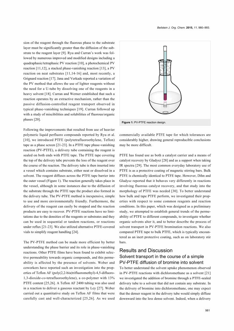
Figure 2: Solvent uptake in the delivery of bromine into dichloromethane (a) 0 min, (b) 0.50 min, (c) 0.83 min, (d) 1.50 min, (e) 3.50 min, (f) 4.17 min,(g) 7.18 min, (h) 10.18 min, (i) 17.18 min, (j) 23.57 min. Note that a part of the delivery tube was obscured by a ground glass joint. The solvent columnreached the maximum height ≈3.5–4 min (just above the top of the ground glass joint) and at that point, the delivery of bromine to the flask began.
tube of bromine was placed in an empty flask, bromine vapors
were observed diffusing through the PTFE tape and descending
to the bottom of the flask [22]. However, when the tip of the
delivery tube was immersed in dichloromethane, initially the
solvent in the flask was quickly drawn up into the delivery tube.
At this point, relatively little bromine had diffused into the
solvent in the flask (Figure 2). Next, after the column height of
the bromine-solvent mixture reached a maximum, it slowly
decreased. During this phase, most of the bromine was deliv-
ered to the flask.
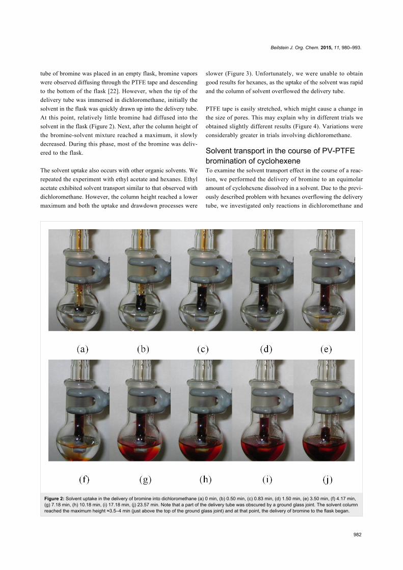
The solvent uptake also occurs with other organic solvents. We
repeated the experiment with ethyl acetate and hexanes. Ethyl
acetate exhibited solvent transport similar to that observed with
dichloromethane. However, the column height reached a lower
maximum and both the uptake and drawdown processes were
slower (Figure 3). Unfortunately, we were unable to obtain
good results for hexanes, as the uptake of the solvent was rapid
and the column of solvent overflowed the delivery tube.
PTFE tape is easily stretched, which might cause a change in
the size of pores. This may explain why in different trials we
obtained slightly different results (Figure 4). Variations were
considerably greater in trials involving dichloromethane.
Solvent transport in the course of PV-PTFEbromination of cyclohexeneTo examine the solvent transport effect in the course of a reac-
tion, we performed the delivery of bromine to an equimolar
amount of cyclohexene dissolved in a solvent. Due to the previ-
ously described problem with hexanes overflowing the delivery
tube, we investigated only reactions in dichloromethane and
Beilstein J. Org. Chem. 2015, 11, 980–993.
983
Figure 3: Solvent column heights of bromine delivery into dichloromethane (○) and ethyl acetate. (♦).
Figure 4: Reproducibility of bromine delivery into a) dichloromethane and b) ethyl acetate. In each case three different trials are shown.
Figure 5: Height of the solvent column in the course of the bromination of cyclohexene in (a) dichloromethane and (b) ethyl acetate. In each casethree different trials are shown.
ethyl acetate. Figure 5 represents the heights of the liquid
columns in the delivery tubes over the course of the reaction.
Again, there are gaps present due to the ground glass joints
preventing the observation of the level of the bromine–solvent
mixture in the delivery tube. As with the previous experiments,
the trials with dichloromethane were less reproducible in terms
Beilstein J. Org. Chem. 2015, 11, 980–993.
984
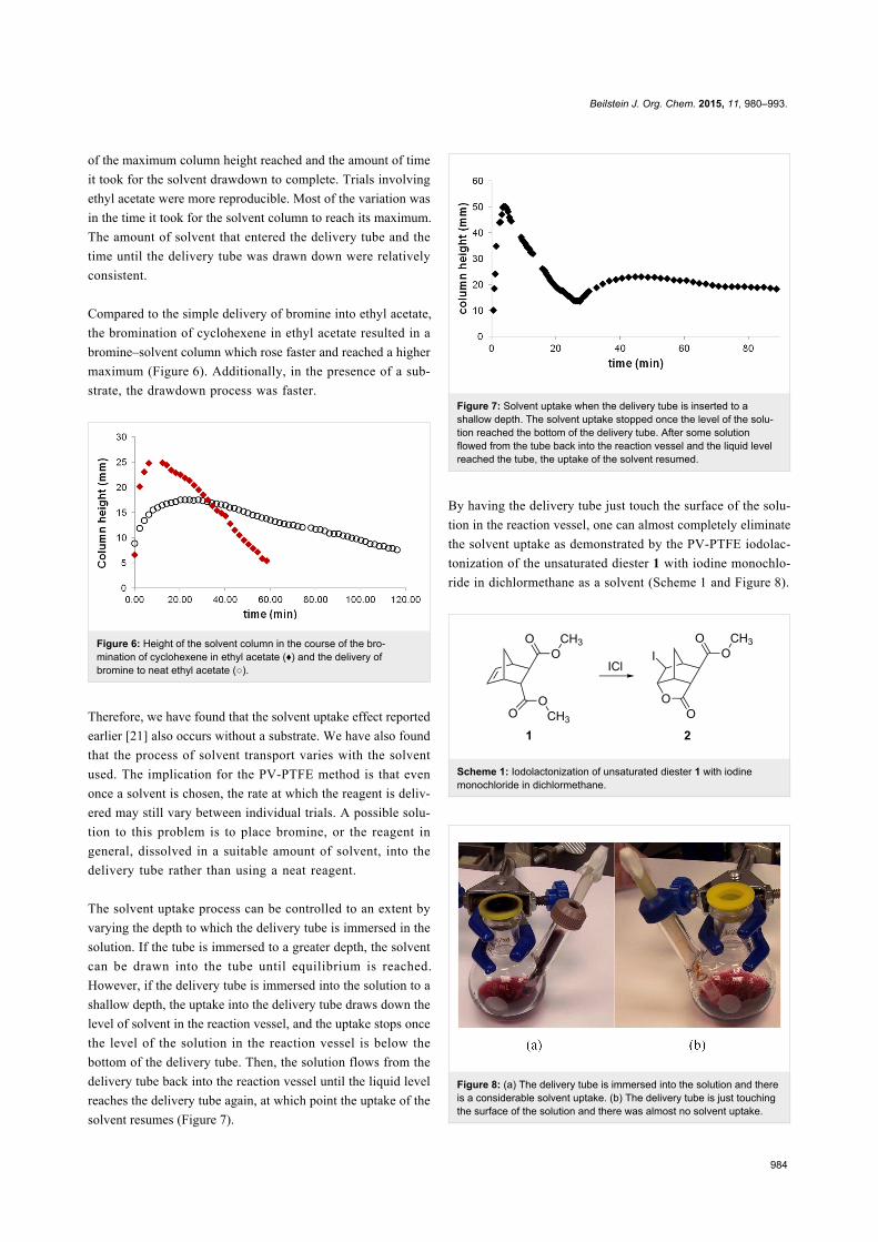
of the maximum column height reached and the amount of time
it took for the solvent drawdown to complete. Trials involving
ethyl acetate were more reproducible. Most of the variation was
in the time it took for the solvent column to reach its maximum.
The amount of solvent that entered the delivery tube and the
time until the delivery tube was drawn down were relatively
consistent.
Compared to the simple delivery of bromine into ethyl acetate,
the bromination of cyclohexene in ethyl acetate resulted in a
bromine–solvent column which rose faster and reached a higher
maximum (Figure 6). Additionally, in the presence of a sub-
strate, the drawdown process was faster.
Figure 6: Height of the solvent column in the course of the bro-mination of cyclohexene in ethyl acetate (♦) and the delivery ofbromine to neat ethyl acetate (○).
Therefore, we have found that the solvent uptake effect reported
earlier [21] also occurs without a substrate. We have also found
that the process of solvent transport varies with the solvent
used. The implication for the PV-PTFE method is that even
once a solvent is chosen, the rate at which the reagent is deliv-
ered may still vary between individual trials. A possible solu-
tion to this problem is to place bromine, or the reagent in
general, dissolved in a suitable amount of solvent, into the
delivery tube rather than using a neat reagent.
The solvent uptake process can be controlled to an extent by
varying the depth to which the delivery tube is immersed in the
solution. If the tube is immersed to a greater depth, the solvent
can be drawn into the tube until equilibrium is reached.
However, if the delivery tube is immersed into the solution to a
shallow depth, the uptake into the delivery tube draws down the
level of solvent in the reaction vessel, and the uptake stops once
the level of the solution in the reaction vessel is below the
bottom of the delivery tube. Then, the solution flows from the
delivery tube back into the reaction vessel until the liquid level
reaches the delivery tube again, at which point the uptake of the
solvent resumes (Figure 7).
Figure 7: Solvent uptake when the delivery tube is inserted to ashallow depth. The solvent uptake stopped once the level of the solu-tion reached the bottom of the delivery tube. After some solutionflowed from the tube back into the reaction vessel and the liquid levelreached the tube, the uptake of the solvent resumed.
By having the delivery tube just touch the surface of the solu-
tion in the reaction vessel, one can almost completely eliminate
the solvent uptake as demonstrated by the PV-PTFE iodolac-
tonization of the unsaturated diester 1 with iodine monochlo-
ride in dichlormethane as a solvent (Scheme 1 and Figure 8).
Scheme 1: Iodolactonization of unsaturated diester 1 with iodinemonochloride in dichlormethane.
Figure 8: (a) The delivery tube is immersed into the solution and thereis a considerable solvent uptake. (b) The delivery tube is just touchingthe surface of the solution and there was almost no solvent uptake.
Beilstein J. Org. Chem. 2015, 11, 980–993.
985
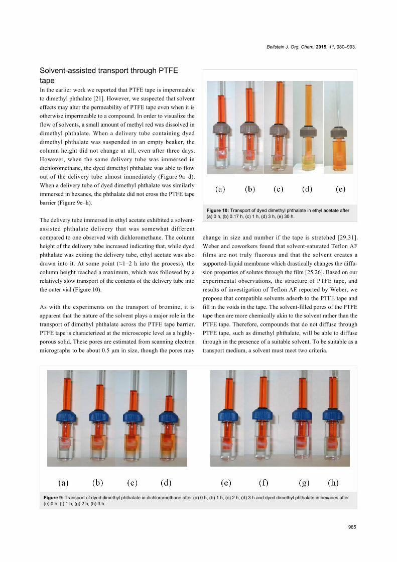
Figure 9: Transport of dyed dimethyl phthalate in dichloromethane after (a) 0 h, (b) 1 h, (c) 2 h, (d) 3 h and dyed dimethyl phthalate in hexanes after(e) 0 h, (f) 1 h, (g) 2 h, (h) 3 h.
Solvent-assisted transport through PTFEtapeIn the earlier work we reported that PTFE tape is impermeable
to dimethyl phthalate [21]. However, we suspected that solvent
effects may alter the permeability of PTFE tape even when it is
otherwise impermeable to a compound. In order to visualize the
flow of solvents, a small amount of methyl red was dissolved in
dimethyl phthalate. When a delivery tube containing dyed
dimethyl phthalate was suspended in an empty beaker, the
column height did not change at all, even after three days.
However, when the same delivery tube was immersed in
dichloromethane, the dyed dimethyl phthalate was able to flow
out of the delivery tube almost immediately (Figure 9a–d).
When a delivery tube of dyed dimethyl phthalate was similarly
immersed in hexanes, the phthalate did not cross the PTFE tape
barrier (Figure 9e–h).
The delivery tube immersed in ethyl acetate exhibited a solvent-
assisted phthalate delivery that was somewhat different
compared to one observed with dichloromethane. The column
height of the delivery tube increased indicating that, while dyed
phthalate was exiting the delivery tube, ethyl acetate was also
drawn into it. At some point (≈1–2 h into the process), the
column height reached a maximum, which was followed by a
relatively slow transport of the contents of the delivery tube into
the outer vial (Figure 10).
As with the experiments on the transport of bromine, it is
apparent that the nature of the solvent plays a major role in the
transport of dimethyl phthalate across the PTFE tape barrier.
PTFE tape is characterized at the microscopic level as a highly-
porous solid. These pores are estimated from scanning electron
micrographs to be about 0.5 μm in size, though the pores may
Figure 10: Transport of dyed dimethyl phthalate in ethyl acetate after(a) 0 h, (b) 0.17 h, (c) 1 h, (d) 3 h, (e) 30 h.
change in size and number if the tape is stretched [29,31].
Weber and coworkers found that solvent-saturated Teflon AF
films are not truly fluorous and that the solvent creates a
supported-liquid membrane which drastically changes the diffu-
sion properties of solutes through the film [25,26]. Based on our
experimental observations, the structure of PTFE tape, and
results of investigation of Teflon AF reported by Weber, we
propose that compatible solvents adsorb to the PTFE tape and
fill in the voids in the tape. The solvent-filled pores of the PTFE
tape then are more chemically akin to the solvent rather than the
PTFE tape. Therefore, compounds that do not diffuse through
PTFE tape, such as dimethyl phthalate, will be able to diffuse
through in the presence of a suitable solvent. To be suitable as a
transport medium, a solvent must meet two criteria.
Beilstein J. Org. Chem. 2015, 11, 980–993.
986
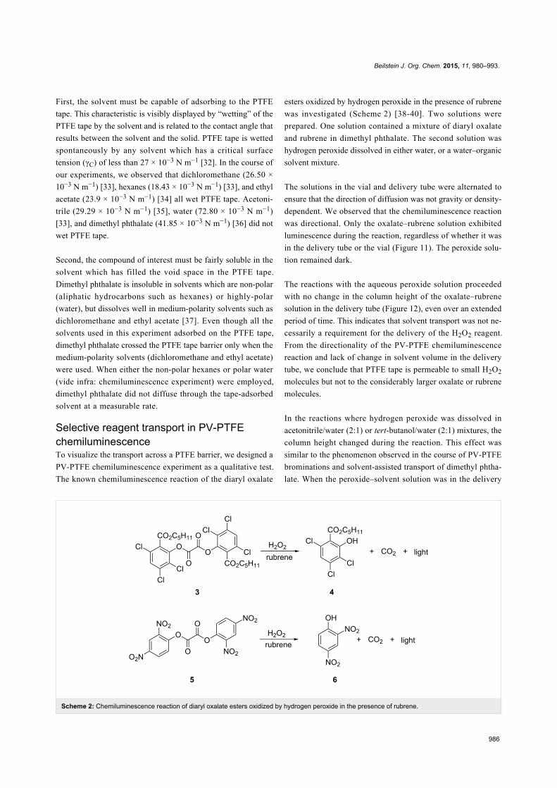
Scheme 2: Chemiluminescence reaction of diaryl oxalate esters oxidized by hydrogen peroxide in the presence of rubrene.
First, the solvent must be capable of adsorbing to the PTFE
tape. This characteristic is visibly displayed by “wetting” of the
PTFE tape by the solvent and is related to the contact angle that
results between the solvent and the solid. PTFE tape is wetted
spontaneously by any solvent which has a critical surface
tension (γC) of less than 27 × 10−3 N m−1 [32]. In the course of
our experiments, we observed that dichloromethane (26.50 ×
10−3 N m−1) [33], hexanes (18.43 × 10⁻³ N m−1) [33], and ethyl
acetate (23.9 × 10⁻³ N m−1) [34] all wet PTFE tape. Acetoni-
trile (29.29 × 10⁻³ N m−1) [35], water (72.80 × 10⁻³ N m−1)
[33], and dimethyl phthalate (41.85 × 10⁻³ N m−1) [36] did not
wet PTFE tape.
Second, the compound of interest must be fairly soluble in the
solvent which has filled the void space in the PTFE tape.
Dimethyl phthalate is insoluble in solvents which are non-polar
(aliphatic hydrocarbons such as hexanes) or highly-polar
(water), but dissolves well in medium-polarity solvents such as
dichloromethane and ethyl acetate [37]. Even though all the
solvents used in this experiment adsorbed on the PTFE tape,
dimethyl phthalate crossed the PTFE tape barrier only when the
medium-polarity solvents (dichloromethane and ethyl acetate)
were used. When either the non-polar hexanes or polar water
(vide infra: chemiluminescence experiment) were employed,
dimethyl phthalate did not diffuse through the tape-adsorbed
solvent at a measurable rate.
Selective reagent transport in PV-PTFEchemiluminescenceTo visualize the transport across a PTFE barrier, we designed a
PV-PTFE chemiluminescence experiment as a qualitative test.
The known chemiluminescence reaction of the diaryl oxalate
esters oxidized by hydrogen peroxide in the presence of rubrene
was investigated (Scheme 2) [38-40]. Two solutions were
prepared. One solution contained a mixture of diaryl oxalate
and rubrene in dimethyl phthalate. The second solution was
hydrogen peroxide dissolved in either water, or a water–organic
solvent mixture.
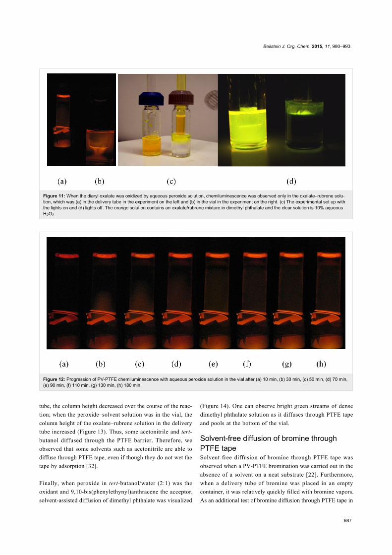
The solutions in the vial and delivery tube were alternated to
ensure that the direction of diffusion was not gravity or density-
dependent. We observed that the chemiluminescence reaction
was directional. Only the oxalate–rubrene solution exhibited
luminescence during the reaction, regardless of whether it was
in the delivery tube or the vial (Figure 11). The peroxide solu-
tion remained dark.
The reactions with the aqueous peroxide solution proceeded
with no change in the column height of the oxalate–rubrene
solution in the delivery tube (Figure 12), even over an extended
period of time. This indicates that solvent transport was not ne-
cessarily a requirement for the delivery of the H2O2 reagent.
From the directionality of the PV-PTFE chemiluminescence
reaction and lack of change in solvent volume in the delivery
tube, we conclude that PTFE tape is permeable to small H2O2
molecules but not to the considerably larger oxalate or rubrene
molecules.
In the reactions where hydrogen peroxide was dissolved in
acetonitrile/water (2:1) or tert-butanol/water (2:1) mixtures, the
column height changed during the reaction. This effect was
similar to the phenomenon observed in the course of PV-PTFE
brominations and solvent-assisted transport of dimethyl phtha-
late. When the peroxide–solvent solution was in the delivery
Beilstein J. Org. Chem. 2015, 11, 980–993.
987
Figure 11: When the diaryl oxalate was oxidized by aqueous peroxide solution, chemiluminescence was observed only in the oxalate–rubrene solu-tion, which was (a) in the delivery tube in the experiment on the left and (b) in the vial in the experiment on the right. (c) The experimental set up withthe lights on and (d) lights off. The orange solution contains an oxalate/rubrene mixture in dimethyl phthalate and the clear solution is 10% aqueousH2O2.
Figure 12: Progression of PV-PTFE chemiluminescence with aqueous peroxide solution in the vial after (a) 10 min, (b) 30 min, (c) 50 min, (d) 70 min,(e) 90 min, (f) 110 min, (g) 130 min, (h) 180 min.
tube, the column height decreased over the course of the reac-
tion; when the peroxide–solvent solution was in the vial, the
column height of the oxalate–rubrene solution in the delivery
tube increased (Figure 13). Thus, some acetonitrile and tert-
butanol diffused through the PTFE barrier. Therefore, we
observed that some solvents such as acetonitrile are able to
diffuse through PTFE tape, even if though they do not wet the
tape by adsorption [32].
Finally, when peroxide in tert-butanol/water (2:1) was the
oxidant and 9,10-bis(phenylethynyl)anthracene the acceptor,
solvent-assisted diffusion of dimethyl phthalate was visualized
(Figure 14). One can observe bright green streams of dense
dimethyl phthalate solution as it diffuses through PTFE tape
and pools at the bottom of the vial.
Solvent-free diffusion of bromine throughPTFE tapeSolvent-free diffusion of bromine through PTFE tape was
observed when a PV-PTFE bromination was carried out in the
absence of a solvent on a neat substrate [22]. Furthermore,
when a delivery tube of bromine was placed in an empty
container, it was relatively quickly filled with bromine vapors.
As an additional test of bromine diffusion through PTFE tape in

Beilstein J. Org. Chem. 2015, 11, 980–993.
988
Figure 13: Progression of PV-PTFE chemiluminescence with acetonitrile–aqueous peroxide solution in the vial after (a) 10 min, (b) 15 min,(c) 20 min, (d) 25 min and tert-butanol–aqueous peroxide solution in the vial after (e) 5 min, (f) 10 min, (g) 15 min, (h) 20 min.
Figure 15: Corrosion of aluminum resulting from bromine applied directly to metal.
Figure 14: Diffusion of dimethyl phthalate assisted by tert-butanolthrough PTFE was visualized in a chemiluminescence reaction inwhich 9,10-bis(phenylethynyl)anthracene and an oxalate ester indimethylphthalate diffused into a solution of hydrogen peroxide (10%)in a mixture of tert-butanol and water (2:1).
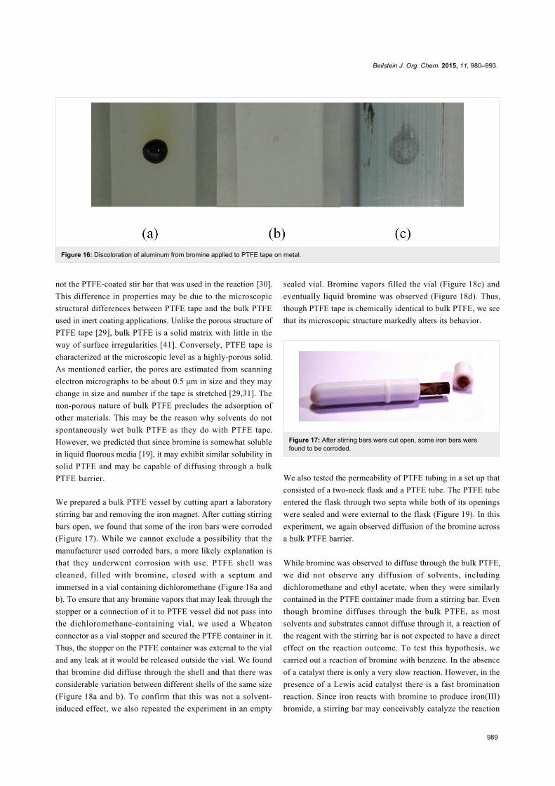
the absence of a solvent, we utilized the reaction of bromine
with aluminum, which discolors the metal. A single drop of
bromine was placed on two sections of an aluminum bar; one
section was exposed aluminum (Figure 15a), the other section
was covered with a single layer of PTFE tape (Figure 16a). The
bromine was allowed to completely evaporate (Figure 15b and
Figure 16b), at which point the PTFE tape was removed. We
found that the discoloration of the aluminum that was covered
with PTFE tape was consistent with the discoloration of the
bare aluminum (Figure 15c and Figure 16c). Therefore, bromine
readily and at a high rate diffused through PTFE tape in the
absence of a solvent.
Comparison of PTFE tape to bulk PTFEDihn and Gladysz reported that in the course of a recovery of
fluorous catalysts, the catalysts attached to the PTFE tape, but
Beilstein J. Org. Chem. 2015, 11, 980–993.
989
Figure 16: Discoloration of aluminum from bromine applied to PTFE tape on metal.
not the PTFE-coated stir bar that was used in the reaction [30].
This difference in properties may be due to the microscopic
structural differences between PTFE tape and the bulk PTFE
used in inert coating applications. Unlike the porous structure of
PTFE tape [29], bulk PTFE is a solid matrix with little in the
way of surface irregularities [41]. Conversely, PTFE tape is
characterized at the microscopic level as a highly-porous solid.
As mentioned earlier, the pores are estimated from scanning
electron micrographs to be about 0.5 μm in size and they may
change in size and number if the tape is stretched [29,31]. The
non-porous nature of bulk PTFE precludes the adsorption of
other materials. This may be the reason why solvents do not
spontaneously wet bulk PTFE as they do with PTFE tape.
However, we predicted that since bromine is somewhat soluble
in liquid fluorous media [19], it may exhibit similar solubility in
solid PTFE and may be capable of diffusing through a bulk
PTFE barrier.
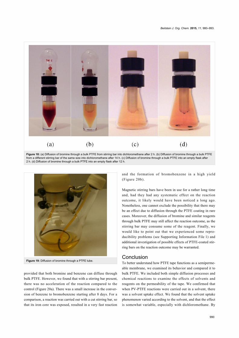
We prepared a bulk PTFE vessel by cutting apart a laboratory
stirring bar and removing the iron magnet. After cutting stirring
bars open, we found that some of the iron bars were corroded
(Figure 17). While we cannot exclude a possibility that the
manufacturer used corroded bars, a more likely explanation is
that they underwent corrosion with use. PTFE shell was
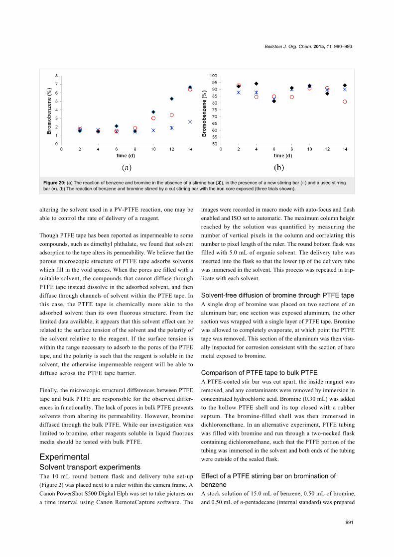
cleaned, filled with bromine, closed with a septum and
immersed in a vial containing dichloromethane (Figure 18a and
b). To ensure that any bromine vapors that may leak through the
stopper or a connection of it to PTFE vessel did not pass into
the dichloromethane-containing vial, we used a Wheaton
connector as a vial stopper and secured the PTFE container in it.
Thus, the stopper on the PTFE container was external to the vial
and any leak at it would be released outside the vial. We found
that bromine did diffuse through the shell and that there was
considerable variation between different shells of the same size
(Figure 18a and b). To confirm that this was not a solvent-
induced effect, we also repeated the experiment in an empty
sealed vial. Bromine vapors filled the vial (Figure 18c) and
eventually liquid bromine was observed (Figure 18d). Thus,
though PTFE tape is chemically identical to bulk PTFE, we see
that its microscopic structure markedly alters its behavior.
Figure 17: After stirring bars were cut open, some iron bars werefound to be corroded.
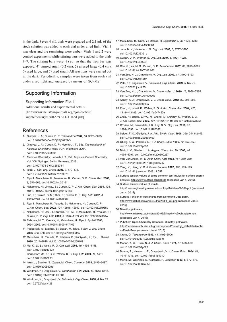
We also tested the permeability of PTFE tubing in a set up that
consisted of a two-neck flask and a PTFE tube. The PTFE tube
entered the flask through two septa while both of its openings
were sealed and were external to the flask (Figure 19). In this
experiment, we again observed diffusion of the bromine across
a bulk PTFE barrier.
While bromine was observed to diffuse through the bulk PTFE,
we did not observe any diffusion of solvents, including
dichloromethane and ethyl acetate, when they were similarly
contained in the PTFE container made from a stirring bar. Even
though bromine diffuses through the bulk PTFE, as most
solvents and substrates cannot diffuse through it, a reaction of
the reagent with the stirring bar is not expected to have a direct
effect on the reaction outcome. To test this hypothesis, we
carried out a reaction of bromine with benzene. In the absence
of a catalyst there is only a very slow reaction. However, in the
presence of a Lewis acid catalyst there is a fast bromination
reaction. Since iron reacts with bromine to produce iron(III)
bromide, a stirring bar may conceivably catalyze the reaction
Beilstein J. Org. Chem. 2015, 11, 980–993.
990
Figure 18: (a) Diffusion of bromine through a bulk PTFE from stirring bar into dichloromethane after 2 h. (b) Diffusion of bromine through a bulk PTFEfrom a different stirring bar of the same size into dichloromethane after 14 h. (c) Diffusion of bromine through a bulk PTFE into an empty flask after2 h. (d) Diffusion of bromine through a bulk PTFE into an empty flask after 12 h.
Figure 19: Diffusion of bromine through a PTFE tube.
provided that both bromine and benzene can diffuse through
bulk PTFE. However, we found that with a stirring bar present,
there was no acceleration of the reaction compared to the
control (Figure 20a). There was a small increase in the conver-
sion of benzene to bromobenzene starting after 8 days. For a
comparison, a reaction was carried out with a cut stirring bar, so
that its iron core was exposed, resulted in a very fast reaction
and the formation of bromobenzene in a high yield
(Figure 20b).
Magnetic stirring bars have been in use for a rather long time
and, had they had any systematic effect on the reaction
outcome, it likely would have been noticed a long ago.
Nonetheless, one cannot exclude the possibility that there may
be an effect due to diffusion through the PTFE coating in rare
cases. Moreover, the diffusion of bromine and similar reagents
through bulk PTFE may still affect the reaction outcome, as the
stirring bar may consume some of the reagent. Finally, we
would like to point out that we experienced some repro-
ducibility problems (see Supporting Information File 1) and
additional investigation of possible effects of PTFE-coated stir-
ring bars on the reaction outcome may be warranted.
ConclusionTo better understand how PTFE tape functions as a semiperme-
able membrane, we examined its behavior and compared it to
bulk PTFE. We included both simple diffusion processes and
chemical reactions to examine the effects of solvents and
reagents on the permeability of the tape. We confirmed that
when PV-PTFE reactions were carried out in a solvent, there
was a solvent uptake effect. We found that the solvent uptake
phenomenon varied according to the solvent, and that the effect
is somewhat variable, especially with dichloromethane. By
Beilstein J. Org. Chem. 2015, 11, 980–993.
991
Figure 20: (a) The reaction of benzene and bromine in the absence of a stirring bar ( ), in the presence of a new stirring bar (○) and a used stirringbar (♦). (b) The reaction of benzene and bromine stirred by a cut stirring bar with the iron core exposed (three trials shown).
altering the solvent used in a PV-PTFE reaction, one may be
able to control the rate of delivery of a reagent.
Though PTFE tape has been reported as impermeable to some
compounds, such as dimethyl phthalate, we found that solvent
adsorption to the tape alters its permeability. We believe that the
porous microscopic structure of PTFE tape adsorbs solvents
which fill in the void spaces. When the pores are filled with a
suitable solvent, the compounds that cannot diffuse through
PTFE tape instead dissolve in the adsorbed solvent, and then
diffuse through channels of solvent within the PTFE tape. In
this case, the PTFE tape is chemically more akin to the
adsorbed solvent than its own fluorous structure. From the
limited data available, it appears that this solvent effect can be
related to the surface tension of the solvent and the polarity of
the solvent relative to the reagent. If the surface tension is
within the range necessary to adsorb to the pores of the PTFE
tape, and the polarity is such that the reagent is soluble in the
solvent, the otherwise impermeable reagent will be able to
diffuse across the PTFE tape barrier.
Finally, the microscopic structural differences between PTFE
tape and bulk PTFE are responsible for the observed differ-
ences in functionality. The lack of pores in bulk PTFE prevents
solvents from altering its permeability. However, bromine
diffused through the bulk PTFE. While our investigation was
limited to bromine, other reagents soluble in liquid fluorous
media should be tested with bulk PTFE.
ExperimentalSolvent transport experimentsThe 10 mL round bottom flask and delivery tube set-up
(Figure 2) was placed next to a ruler within the camera frame. A
Canon PowerShot S500 Digital Elph was set to take pictures on
a time interval using Canon RemoteCapture software. The
images were recorded in macro mode with auto-focus and flash
enabled and ISO set to automatic. The maximum column height
reached by the solution was quantified by measuring the
number of vertical pixels in the column and correlating this
number to pixel length of the ruler. The round bottom flask was
filled with 5.0 mL of organic solvent. The delivery tube was
inserted into the flask so that the lower tip of the delivery tube
was immersed in the solvent. This process was repeated in trip-
licate with each solvent.
Solvent-free diffusion of bromine through PTFE tapeA single drop of bromine was placed on two sections of an
aluminum bar; one section was exposed aluminum, the other
section was wrapped with a single layer of PTFE tape. Bromine
was allowed to completely evaporate, at which point the PTFE
tape was removed. This section of the aluminum was then visu-
ally inspected for corrosion consistent with the section of bare
metal exposed to bromine.
Comparison of PTFE tape to bulk PTFEA PTFE-coated stir bar was cut apart, the inside magnet was
removed, and any contaminants were removed by immersion in
concentrated hydrochloric acid. Bromine (0.30 mL) was added
to the hollow PTFE shell and its top closed with a rubber
septum. The bromine-filled shell was then immersed in
dichloromethane. In an alternative experiment, PTFE tubing
was filled with bromine and run through a two-necked flask
containing dichloromethane, such that the PTFE portion of the
tubing was immersed in the solvent and both ends of the tubing
were outside of the sealed flask.
Effect of a PTFE stirring bar on bromination ofbenzeneA stock solution of 15.0 mL of benzene, 0.50 mL of bromine,
and 0.50 mL of n-pentadecane (internal standard) was prepared
Beilstein J. Org. Chem. 2015, 11, 980–993.
992
in the dark. Seven 4 mL vials were prepared and 2.1 mL of the
stock solution was added to each vial under a red light. Vial 1
was clear and the remaining were amber. Vials 1 and 2 were
control experiments while stirring bars were added to the vials
3–7. The stirring bars were: 3) cut so that the iron bar was
exposed, 4) unused small (0.2 cm), 5) unused large (0.4 cm),
6) used large, and 7) used small. All reactions were carried out
in the dark. Periodically, samples were taken from each vial
under a red light and analyzed by means of GC–MS.
Supporting InformationSupporting Information File 1Additional results and experimental details.
[http://www.beilstein-journals.org/bjoc/content/
supplementary/1860-5397-11-110-S1.pdf]
References1. Gladysz, J. A.; Curran, D. P. Tetrahedron 2002, 58, 3823–3825.
doi:10.1016/S0040-4020(02)00222-32. Gladysz, J. A.; Curran, D. P.; Horváth, I. T., Eds. The Handbook of
Fluorous Chemistry; Wiley-VCH: Weinheim, 2004.doi:10.1002/3527603905
3. Fluorous Chemistry; Horváth, I. T., Ed.; Topics in Current Chemistry,Vol. 308; Springer: Berlin, Germany, 2012.doi:10.1007/978-3-642-25234-1
4. Iskra, J. Lett. Org. Chem. 2006, 3, 170–175.doi:10.2174/157017806775789976
5. Ryu, I.; Matsubara, H.; Nakamura, H.; Curran, D. P. Chem. Rec. 2008,8, 351–363. doi:10.1002/tcr.20161
6. Nakamura, H.; Linclau, B.; Curran, D. P. J. Am. Chem. Soc. 2001, 123,10119–10120. doi:10.1021/ja011716c
7. Luo, Z.; Swaleh, S. M.; Theil, F.; Curran, D. P. Org. Lett. 2002, 4,2585–2587. doi:10.1021/ol026232f
8. Ryu, I.; Matsubara, H.; Yasuda, S.; Nakamura, H.; Curran, D. P.J. Am. Chem. Soc. 2002, 124, 12946–12947. doi:10.1021/ja027965y
9. Nakamura, H.; Usui, T.; Kuroda, H.; Ryu, I.; Matsubara, H.; Yasuda, S.;Curran, D. P. Org. Lett. 2003, 5, 1167–1169. doi:10.1021/ol034060w
10. Rahman, M. T.; Kamata, N.; Matsubara, H.; Ryu, I. Synlett 2005,2664–2666. doi:10.1055/s-2005-917103
11. Podgoršek, A.; Stavber, S.; Zupan, M.; Iskra, J. Eur. J. Org. Chem.2006, 483–488. doi:10.1002/ejoc.200500355
12. Matsubara, H.; Tsukida, M.; Ishihara, D.; Kuniyoshi, K.; Ryu, I. Synlett2010, 2014–2018. doi:10.1055/s-0030-1258482
13. Ma, K.; Li, S.; Weiss, R. G. Org. Lett. 2008, 10, 4155–4158.doi:10.1021/ol801327nCorrection: Ma, K.; Li, S.; Weiss, R. G. Org. Lett. 2009, 11, 1461.doi:10.1021/ol900201t
14. Iskra, J.; Stavber, S.; Zupan, M. Chem. Commun. 2003, 2496–2497.doi:10.1039/b305629e
15. Windmon, N.; Dragojlovic, V. Tetrahedron Lett. 2008, 49, 6543–6546.doi:10.1016/j.tetlet.2008.09.007
16. Windmon, N.; Dragojlovic, V. Beilstein J. Org. Chem. 2008, 4, No. 29.doi:10.3762/bjoc.4.29
17. Matsubara, H.; Niwa, Y.; Matake, R. Synlett 2015, 26, 1276–1280.doi:10.1055/s-0034-1380381
18. Jana, N. K.; Verkade, J. G. Org. Lett. 2003, 5, 3787–3790.doi:10.1021/ol035391b
19. Curran, D. P.; Werner, S. Org. Lett. 2004, 6, 1021–1024.doi:10.1021/ol0499248
20. Chu, Q.; Yu, M. S.; Curran, D. P. Tetrahedron 2007, 63, 9890–9895.doi:10.1016/j.tet.2007.06.092
21. Van Zee, N. J.; Dragojlovic, V. Org. Lett. 2009, 11, 3190–3193.doi:10.1021/ol901450h
22. Pels, K.; Dragojlovic, V. Beilstein J. Org. Chem. 2009, 5, No. 75.doi:10.3762/bjoc.5.75
23. Van Zee, N. J.; Dragojlovic, V. Chem. – Eur. J. 2010, 16, 7950–7958.doi:10.1002/chem.201000269
24. Abney, A. J.; Dragojlovic, V. J. Chem. Educ. 2012, 89, 293–295.doi:10.1021/ed200080m
25. Zhao, H.; Ismail, K.; Weber, S. G. J. Am. Chem. Soc. 2004, 126,13184–13185. doi:10.1021/ja047453e
26. Zhao, H.; Zhang, J.; Wu, N.; Zhang, X.; Crowley, K.; Weber, S. G.J. Am. Chem. Soc. 2005, 127, 15112–15119. doi:10.1021/ja052875p
27. O’Brien, M.; Baxendale, I. R.; Ley, S. V. Org. Lett. 2010, 12,1596–1598. doi:10.1021/ol100322t
28. Seidel, F. O.; Gladysz, J. A. Adv. Synth. Catal. 2008, 350, 2443–2449.doi:10.1002/adsc.200800403
29. Oberg, K. A.; Palleros, D. R. J. Chem. Educ. 1995, 72, 857–859.doi:10.1021/ed072p857
30. Dinh, L. V.; Gladysz, J. A. Angew. Chem., Int. Ed. 2005, 44,4095–4097. doi:10.1002/anie.200500237
31. Van Der Linden, W. E. Anal. Chim. Acta 1983, 151, 359–369.doi:10.1016/S0003-2670(00)80097-5
32. Yang, Y.; Liang, Y. C. J. Power Sources 2007, 165, 185–195.doi:10.1016/j.jpowsour.2006.11.059
33. Surface tension values of some common test liquids for surface energyanalysis. http://www.surface-tension.de (accessed Jan 4, 2015).
34. Surface tension values of liquids.http://user.engineering.uiowa.edu/~cfd/pdfs/tables/1-39b.pdf (accessedJan 4, 2015).
35. Surface Tension of Acetonitrile from Dortmund Data Bank.http://www.ddbst.com/en/EED/PCP/SFT_C3.php (accessed Jan 4,2015).
36. Dimethyl phthalate.http://www.microkat.gr/msdspd90-99/Dimethyl%20phthalate.htm(accessed Jan 4, 2015).
37. Pubchem Open Chemistry Database, Dimethyl phthalate.http://pubchem.ncbi.nlm.nih.gov/compound/Dimethyl_phthalate#section=Flash-Point (accessed Jan 4, 2015).
38. Orosz, G. Tetrahedron 1989, 45, 3493–3506.doi:10.1016/S0040-4020(01)81028-0
39. Mohan, A. G.; Turro, N. J. J. Chem. Educ. 1974, 51, 528–529.doi:10.1021/ed051p528
40. Duarte, R.; Nielsen, J. T.; Dragojlovic, V. J. Chem. Educ. 2004, 81,1010–1015. doi:10.1021/ed081p1010
41. Morra, M.; Occhiello, E.; Garbassi, F. Langmuir 1989, 5, 872–876.doi:10.1021/la00087a050
Beilstein J. Org. Chem. 2015, 11, 980–993.
993
License and TermsThis is an Open Access article under the terms of the
Creative Commons Attribution License
(http://creativecommons.org/licenses/by/2.0), which
permits unrestricted use, distribution, and reproduction in
any medium, provided the original work is properly cited.
The license is subject to the Beilstein Journal of Organic
Chemistry terms and conditions:
(http://www.beilstein-journals.org/bjoc)
The definitive version of this article is the electronic one
which can be found at:
doi:10.3762/bjoc.11.110