property of american airlines - amazon s3...jan 07, 2013 · foreword 3121215 – jlg lift – a...
TRANSCRIPT

ANSI ®
Operation and Safety ManualOriginal Instructions - Keep this manual with the machine at all times.
Boom Lift ModelsE400AE400A NarrowE400AJPE400AJP NarrowM400AM400A NarrowM400AJPM400AJP Narrow
3121215January 7, 2013
Prope
rty o
f Am
erica
n Airli
nes

Prope
rty o
f Am
erica
n Airli
nes

FOREWORD
a
l times.
lessors, and lessees with the precautions anderation for its intended purpose.
erves the right to make specification changesformation.an
Airli
nes
3121215 – JLG Lift –
FOREWORD
This manual is a very important tool! Keep it with the machine at al
The purpose of this manual is to provide owners, users, operators,operating procedures essential for the safe and proper machine op
Due to continuous product improvements, JLG Industries, Inc. reswithout prior notification. Contact JLG Industries, Inc. for updated in
Prope
rty o
f Am
eric

FOREWORD
b 3121215
SIGNAL WORDS
INDIAVOWIL
INDAVODEC
OTENTIALLY HAZARDOUS SITUATION. IF NOTRESULT IN MINOR OR MODERATE INJURY. IT MAYINST UNSAFE PRACTICES. THIS DECAL WILL HAVE AOUND.
RMATION OR A COMPANY POLICY THAT RELATESDIRECTLY TO THE SAFETY OF PERSONNEL OR PRO-PERTY.
the potential personalymbol to avoid possiblean
Airli
nes
– JLG Lift –
SAFETY ALERT SYMBOLS AND SAFETY
CATES AN IMMINENTLY HAZARDOUS SITUATION. IF NOTIDED, WILL RESULT IN SERIOUS INJURY OR DEATH. THIS DECALL HAVE A RED BACKGROUND.
ICATES A POTENTIALLY HAZARDOUS SITUATION. IF NOTIDED, COULD RESULT IN SERIOUS INJURY OR DEATH. THISAL WILL HAVE AN ORANGE BACKGROUND.
INDICATES A PAVOIDED, MAY ALSO ALERT AGAYELLOW BACKGR
INDICATES INFODIRECTLY OR INTECTION OF PRO
This is the Safety Alert Symbol. It is used to alert you toinjury hazards. Obey all safety messages that follow this sinjury or death
Prope
rty o
f Am
eric

FOREWORD
c
act:
uct Safety and Reliability Department Industries, Inc.4 Fountainhead Plaza
erstown, MD 21742
our Local JLG Office addresses on inside of manual cover)
A:
Free: 877-JLG-SAFE (877-554-7233)
ide USA:
ne: 240-420-2661 301-745-3713ail: [email protected]
ent Reporting
ct Safety Publica-
nt Owner Updates
tions Regarding ct Safety
• Standards and Regulations Compliance Information
• Questions Regarding Spe-cial Product Applications
• Questions Regarding Prod-uct Modificationsan
Airli
nes
3121215 – JLG Lift –
THIS PRODUCT MUST COMPLY WITH ALL SAFETY RELATED BULLE-TINS. CONTACT JLG INDUSTRIES, INC. OR THE LOCAL AUTHORIZEDJLG REPRESENTATIVE FOR INFORMATION REGARDING SAFETY-RELATED BULLETINS WHICH MAY HAVE BEEN ISSUED FOR THISPRODUCT.
JLG INDUSTRIES, INC. SENDS SAFETY RELATED BULLETINS TO THEOWNER OF RECORD OF THIS MACHINE. CONTACT JLG INDUSTRIES,INC. TO ENSURE THAT THE CURRENT OWNER RECORDS AREUPDATED AND ACCURATE.
JLG INDUSTRIES, INC. MUST BE NOTIFIED IMMEDIATELY IN ALLINSTANCES WHERE JLG PRODUCTS HAVE BEEN INVOLVED IN ANACCIDENT INVOLVING BODILY INJURY OR DEATH OF PERSONNEL ORWHEN SUBSTANTIAL DAMAGE HAS OCCURRED TO PERSONAL PROP-ERTY OR THE JLG PRODUCT.
Cont
ProdJLG1322HagUSA
or Y(See
In US
Toll
Outs
PhoFax:E-m
For:• Accid
• Produtions
• Curre
• QuesProdu
Prope
rty o
f Am
eric

FOREWORD
d 3121215
O
R
R
R
R
R
an A
irline
s
– JLG Lift –
REVISION LOG
riginal Issue - June 6, 2005
evised - July 21, 2006
evised - December 3, 2009
evised - November 9, 2011
evised - August 20, 2012
evised - January 7, 2013
Prope
rty o
f Am
eric

TABLE OF CONTENTS
3121 i
SEC - PARAGRAPH, SUBJECT PAGE
SEC
SECRATI
General . . . . . . . . . . . . . . . . . . . . . . . . . . . . . . . . 2-9
- 3 - MACHINE CONTROLS AND INDICATORS
GENERAL . . . . . . . . . . . . . . . . . . . . . . . . . . . . . . . . 3-1CONTROLS AND INDICATORS . . . . . . . . . . . . . . . 3-1
Ground Control Station . . . . . . . . . . . . . . . . . . . . 3-1Platform Station . . . . . . . . . . . . . . . . . . . . . . . . . . 3-6Platform Control Indicator Panel . . . . . . . . . . . . 3-12
- 4 - MACHINE OPERATION
DESCRIPTION. . . . . . . . . . . . . . . . . . . . . . . . . . . . . 4-1OPERATING CHARACTERISTICS AND
LIMITATIONS . . . . . . . . . . . . . . . . . . . . . . . . . . . . 4-1Capacities . . . . . . . . . . . . . . . . . . . . . . . . . . . . . . 4-1Stability . . . . . . . . . . . . . . . . . . . . . . . . . . . . . . . . 4-2
MOTOR OPERATION . . . . . . . . . . . . . . . . . . . . . . . 4-2Power/Emergency Stop . . . . . . . . . . . . . . . . . . . 4-2Platform/Ground Select Switch. . . . . . . . . . . . . . 4-5Motor Activation. . . . . . . . . . . . . . . . . . . . . . . . . . 4-5
TRAVELING (DRIVING) . . . . . . . . . . . . . . . . . . . . . . 4-5Traveling Forward and Reverse . . . . . . . . . . . . . 4-6
STEERING. . . . . . . . . . . . . . . . . . . . . . . . . . . . . . . . 4-6PLATFORM . . . . . . . . . . . . . . . . . . . . . . . . . . . . . . . 4-7
Loading From Ground Level . . . . . . . . . . . . . . . . 4-7Loading From Positions Above Ground Level . . 4-7
an A
irline
s
215 – JLG Lift –
TION - PARAGRAPH, SUBJECT PAGE SECTION
TION - 1 - SAFETY PRECAUTIONS
1.1 GENERAL . . . . . . . . . . . . . . . . . . . . . . . . . . . . . . . . .1-11.2 PRE-OPERATION . . . . . . . . . . . . . . . . . . . . . . . . . . .1-1
Operator Training and Knowledge. . . . . . . . . . . 1-1Workplace Inspection. . . . . . . . . . . . . . . . . . . . . 1-2Machine Inspection . . . . . . . . . . . . . . . . . . . . . . 1-2
1.3 OPERATION . . . . . . . . . . . . . . . . . . . . . . . . . . . . . . .1-3General . . . . . . . . . . . . . . . . . . . . . . . . . . . . . . . . 1-3Trip and Fall Hazards . . . . . . . . . . . . . . . . . . . . . 1-3Electrocution Hazards . . . . . . . . . . . . . . . . . . . . 1-4Tipping Hazards . . . . . . . . . . . . . . . . . . . . . . . . . 1-6Crushing and Collision Hazards. . . . . . . . . . . . . 1-7
1.4 TOWING, LIFTING, AND HAULING . . . . . . . . . . . . .1-81.5 ADDITIONAL HAZARDS / SAFETY . . . . . . . . . . . . .1-9
TION - 2 - USER RESPONSIBILITIES, MACHINE PREPA-ON, AND INSPECTION
2.1 PERSONNEL TRAINING . . . . . . . . . . . . . . . . . . . . .2-1Operator Training . . . . . . . . . . . . . . . . . . . . . . . . 2-1Training Supervision. . . . . . . . . . . . . . . . . . . . . . 2-1Operator Responsibility . . . . . . . . . . . . . . . . . . . 2-1
2.2 PREPARATION, INSPECTION, AND MAINTENANCE . . . . . . . . . . . . . . . . . . . . . . . . . . .2-2Pre-Start Inspection . . . . . . . . . . . . . . . . . . . . . . 2-4Function Check. . . . . . . . . . . . . . . . . . . . . . . . . . 2-5
SECTION
3.13.2
SECTION
4.14.2
4.3
4.4
4.54.6
Prope
rty o
f Am
eric
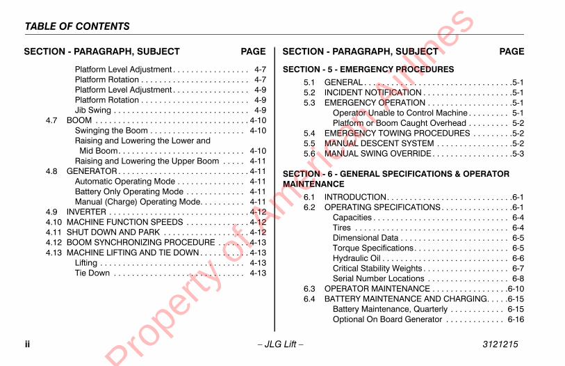
TABLE OF CONTENTS
ii 3121215
SECTIO RAGRAPH, SUBJECT PAGE
4.7
4.8
4.94.104.114.124.13
EMERGENCY PROCEDURES
ERAL . . . . . . . . . . . . . . . . . . . . . . . . . . . . . . . . .5-1IDENT NOTIFICATION . . . . . . . . . . . . . . . . . . . .5-1RGENCY OPERATION . . . . . . . . . . . . . . . . . . .5-1
perator Unable to Control Machine . . . . . . . . . 5-1atform or Boom Caught Overhead . . . . . . . . . 5-2RGENCY TOWING PROCEDURES . . . . . . . . .5-2UAL DESCENT SYSTEM . . . . . . . . . . . . . . . . .5-2UAL SWING OVERRIDE . . . . . . . . . . . . . . . . . .5-3
GENERAL SPECIFICATIONS & OPERATOR E
ODUCTION. . . . . . . . . . . . . . . . . . . . . . . . . . . .6-1RATING SPECIFICATIONS. . . . . . . . . . . . . . . .6-1
apacities . . . . . . . . . . . . . . . . . . . . . . . . . . . . . . 6-4res . . . . . . . . . . . . . . . . . . . . . . . . . . . . . . . . . . 6-4imensional Data . . . . . . . . . . . . . . . . . . . . . . . . 6-5rque Specifications. . . . . . . . . . . . . . . . . . . . . 6-5
ydraulic Oil . . . . . . . . . . . . . . . . . . . . . . . . . . . . 6-6ritical Stability Weights . . . . . . . . . . . . . . . . . . . 6-7rial Number Locations . . . . . . . . . . . . . . . . . . 6-8RATOR MAINTENANCE . . . . . . . . . . . . . . . . .6-10TERY MAINTENANCE AND CHARGING. . . . .6-15attery Maintenance, Quarterly . . . . . . . . . . . . 6-15ptional On Board Generator . . . . . . . . . . . . . 6-16
an A
irline
s
– JLG Lift –
N - PARAGRAPH, SUBJECT PAGE SECTION - PA
Platform Level Adjustment . . . . . . . . . . . . . . . . . 4-7Platform Rotation . . . . . . . . . . . . . . . . . . . . . . . . 4-7Platform Level Adjustment . . . . . . . . . . . . . . . . . 4-9Platform Rotation . . . . . . . . . . . . . . . . . . . . . . . . 4-9Jib Swing . . . . . . . . . . . . . . . . . . . . . . . . . . . . . . 4-9
BOOM . . . . . . . . . . . . . . . . . . . . . . . . . . . . . . . . . . 4-10Swinging the Boom . . . . . . . . . . . . . . . . . . . . . 4-10Raising and Lowering the Lower and Mid Boom. . . . . . . . . . . . . . . . . . . . . . . . . . . . 4-10Raising and Lowering the Upper Boom . . . . . 4-11
GENERATOR . . . . . . . . . . . . . . . . . . . . . . . . . . . . . 4-11Automatic Operating Mode . . . . . . . . . . . . . . . 4-11Battery Only Operating Mode . . . . . . . . . . . . . 4-11Manual (Charge) Operating Mode. . . . . . . . . . 4-11
INVERTER . . . . . . . . . . . . . . . . . . . . . . . . . . . . . . . 4-12MACHINE FUNCTION SPEEDS . . . . . . . . . . . . . . 4-12SHUT DOWN AND PARK . . . . . . . . . . . . . . . . . . . 4-12BOOM SYNCHRONIZING PROCEDURE . . . . . . . 4-13MACHINE LIFTING AND TIE DOWN . . . . . . . . . . . 4-13
Lifting . . . . . . . . . . . . . . . . . . . . . . . . . . . . . . . . 4-13Tie Down . . . . . . . . . . . . . . . . . . . . . . . . . . . . . 4-13
SECTION - 5 -
5.1 GEN5.2 INC5.3 EME
OPl
5.4 EME5.5 MAN5.6 MAN
SECTION - 6 - MAINTENANC
6.1 INTR6.2 OPE
CTiDToHCSe
6.3 OPE6.4 BAT
BO
Prope
rty o
f Am
eric

TABLE OF CONTENTS
3121 iii
SEC - PARAGRAPH, SUBJECT PAGE
SEC
Grade and Side Slopes . . . . . . . . . . . . . . . . . . . . . 4-8Lifting Chart. . . . . . . . . . . . . . . . . . . . . . . . . . . . . . 4-14Chassis & Platform Tie Down - Sheet 1 of 2 . . . . 4-15Chassis & Platform Tie Down - Sheet 2 of 2 . . . . 4-16Decal Installation - Sheet 1 of 3 . . . . . . . . . . . . . . 4-17Decal Installation - Sheet 2 of 3 . . . . . . . . . . . . . . 4-18Decal Installation - Sheet 3 of 3 . . . . . . . . . . . . . . 4-19Serial Number Locations . . . . . . . . . . . . . . . . . . . . 6-8Operator Maintenance & Lubrication Diagram . . . 6-9an
Airli
nes
215 – JLG Lift –
TION - PARAGRAPH, SUBJECT PAGE SECTION
Battery Charging (On Board Charger) . . . . . . . 6-166.5 TIRES & WHEELS . . . . . . . . . . . . . . . . . . . . . . . . .6-17
Tire Inflation . . . . . . . . . . . . . . . . . . . . . . . . . . . 6-17Tire Damage . . . . . . . . . . . . . . . . . . . . . . . . . . . 6-17Tire Replacement . . . . . . . . . . . . . . . . . . . . . . . 6-17Wheel Replacement . . . . . . . . . . . . . . . . . . . . . 6-18Wheel Installation . . . . . . . . . . . . . . . . . . . . . . . 6-18
6.6 SUPPLEMENTAL INFORMATION . . . . . . . . . . . . .6-19
TION - 7 - INSPECTION AND REPAIR LOG
LIST OF FIGURES
2-1. Basic Nomenclature. . . . . . . . . . . . . . . . . . . . . . . . .2-72-2. Daily Walk-Around Inspection - Sheet 1 of 3 . . . . . .2-82-3. Daily Walk-Around Inspection - Sheet 2 of 3 . . . . . .2-92-4. Daily Walk-Around Inspection - Sheet 3 of 3 . . . . .2-103-1. Ground Control Station . . . . . . . . . . . . . . . . . . . . . .3-33-2. Ground Control Station w/ Function Enable . . . . . .3-43-3. Platform Control Console. . . . . . . . . . . . . . . . . . . . .3-73-4. Platform Control Console w/ Drive Orientation . . . .3-83-5. Platform Control Indicator Panel . . . . . . . . . . . . . .3-133-6. Platform Control Indicator Panel
w/Drive Orientation. . . . . . . . . . . . . . . . . . . . . . . .3-134-1. Position of Least Forward Stability . . . . . . . . . . . . .4-34-2. Position of Least Backward Stability . . . . . . . . . . . .4-4
4-3.4-4.4-5.4-6.4-7.4-8.4-9.6-1.6-2.
Prope
rty o
f Am
eric

TABLE OF CONTENTS
iv 3121215
SECTIO RAGRAPH, SUBJECT PAGE
1-11-22-13-14-1
4-2
4-3
4-4
6-1
6-2
6-36-46-56-66-76-86-96-10
rication Specifications. . . . . . . . . . . . . . . . . . . 6-10el Torque Chart . . . . . . . . . . . . . . . . . . . . . . . 6-19ection and Repair Log . . . . . . . . . . . . . . . . . . . 7-1
an A
irline
s
– JLG Lift –
N - PARAGRAPH, SUBJECT PAGE SECTION - PA
LIST OF TABLES
Minimum Approach Distances (M.A.D.) . . . . . . . . . 1-5Beaufort Scale (For Reference Only) . . . . . . . . . . 1-10Inspection and Maintenance Table . . . . . . . . . . . . . 2-3Simultaneous Functions. . . . . . . . . . . . . . . . . . . . . 3-11E400A/E400AJP Decal Legend - Prior to S/N 0300142589 . . . . . . . . . . . . . . . . . . . 4-20E400A/E400AJP Decal Legend - S/N 0300142589 to Present. . . . . . . . . . . . . . . . . 4-26M400A/M400AJ Decal Legend - Prior to S/N 0300142589 . . . . . . . . . . . . . . . . . . . 4-32M400A/M400AJ Decal Legend - S/N 0300142589 to Present. . . . . . . . . . . . . . . . . 4-37Operating Specifications - Prior to S/N 0300142589 . . . . . . . . . . . . . . . . . . . . . . . . . . 6-1Operating Specifications - S/N 0300142589 to Present. . . . . . . . . . . . . . . . . . . . . . . . . . . . . . . . 6-2Capacities . . . . . . . . . . . . . . . . . . . . . . . . . . . . . . . . 6-4Tire Specifications . . . . . . . . . . . . . . . . . . . . . . . . . . 6-4Dimensional Data. . . . . . . . . . . . . . . . . . . . . . . . . . . 6-5Torque Requirements . . . . . . . . . . . . . . . . . . . . . . . 6-5Hydraulic Oil . . . . . . . . . . . . . . . . . . . . . . . . . . . . . . 6-6Mobil DTE 11M Specs . . . . . . . . . . . . . . . . . . . . . . . 6-6Mobil EAL H Series Specs. . . . . . . . . . . . . . . . . . . . 6-7Critical Stability Weights . . . . . . . . . . . . . . . . . . . . . 6-7
6-11 Lub6-12 Whe7-1 Insp
Prope
rty o
f Am
eric

SECTION 1 - SAFETY PRECAUTIONS
1-1
CAUTIONS
E-OPERATION
Training and Knowledged and understand this manual before operating thehine.
not operate this machine until complete training is per-ed by authorized persons.
y authorized and qualified personnel can operate thehine.
an A
irline
s
3121215 – JLG Lift –
SECTION 1. SAFETY PRE
1.1 GENERALThis section outlines the necessary precautions for properand safe machine operation and maintenance. For propermachine use, it is mandatory that a daily routine is estab-lished based on the content of this manual. A maintenanceprogram, using the information provided in this manual andthe Service and Maintenance Manual, must also be estab-lished by a qualified person and followed to ensure themachine is safe to operate.
The owner/user/operator/lessor/lessee of the machineshould not operate the machine until this manual has beenread, training is accomplished, and operation of the machinehas been completed under the supervision of an experi-enced and qualified operator.
If there are any questions with regard to safety, training,inspection, maintenance, application, and operation, pleasecontact JLG Industries, Inc. (“JLG”).
FAILURE TO COMPLY WITH THE SAFETY PRECAUTIONS LISTED INTHIS MANUAL COULD RESULT IN MACHINE DAMAGE, PROPERTY DAM-AGE, PERSONAL INJURY OR DEATH.
1.2 PR
Operator• Rea
mac
• Do form
• Onlmac
Prope
rty o
f Am
eric

SECTION 1 - SAFETY PRECAUTIONS
1-2 3121215
Wo
pection achine operation, perform inspections and func-
hecks. Refer to Section 2 of this manual for instructions.
perate this machine until it has been serviced anded according to requirements specified in theand Maintenance Manual.
the footswitch and all other safety devices areg properly. Modification of these devices is aolation.
R ALTERATION OF AN AERIAL WORK PLATFORMNLY WITH WRITTEN PERMISSION FROM THE MANU-
perate any machine on which safety or instruction or decals are missing or illegible.
ny buildup of debris on the platform floor. Keep, grease, and other slippery substances from foot-d platform floor.
an A
irline
s
– JLG Lift –
• Read, understand, and obey all DANGERS, WARNINGS,CAUTIONS, and operating instructions on the machineand in this manual.
• Use the machine in a manner which is within the scope ofits intended application set by JLG.
• All operating personnel must be familiar with the emer-gency controls and emergency operation of the machineas specified in this manual.
• Read, understand, and obey all applicable employer,local, and governmental regulations as they pertain tooperation of the machine.
rkplace Inspection• The operator is to take safety measures to avoid all haz-
ards in the work area prior to machine operation.
• Do not operate or raise the platform while on trucks, trail-ers, railway cars, floating vessels, scaffolds or other equip-ment unless approved in writing by JLG.
• Do not operate the machine in hazardous environmentsunless approved for that purpose by JLG.
• Be sure that the ground conditions are able to support themaximum load shown on the decals located on themachine.
Machine Ins• Before m
tional cdetailed
• Do not omaintainService
• Be sureoperatinsafety vi
MODIFICATION OSHALL BE MADE OFACTURER
• Do not oplacards
• Avoid amud, oilwear an
Prope
rty o
f Am
eric

SECTION 1 - SAFETY PRECAUTIONS
1-3
plies or tools which extend outside the platform arehibited unless approved by JLG.
en driving, always position boom over rear axle in line the direction of travel. Remember, if boom is over thet axle, steer and drive functions will be reversed.
not assist a stuck or disabled machine by pushing,ing, or by using boom functions. Only pull the unit the tie-down lugs on the chassis.
not place boom or platform against any structure tody the platform or to support the structure.
w boom and shut off all power before leaving machine.
Fall Hazards operation, occupants in the platform must wear a fullarness with a lanyard attached to an authorized lan-
nchorage point. Attach only one (1) lanyard per lan-nchorage point.
an A
irline
s
3121215 – JLG Lift –
1.3 OPERATION
General • Do not use the machine for any purpose other than posi-
tioning personnel, their tools, and equipment.
• Never operate a machine that is not working properly. If amalfunctions occurs, shut down the machine.
• Never slam a control switch or lever through neutral to anopposite direction. Always return switch to neutral andstop before moving the switch to the next function. Oper-ate controls with slow and even pressure.
• Do not allow personnel to tamper with or operate themachine from the ground with personnel in the platform,except in an emergency.
• Do not carry materials directly on platform railing. ContactJLG for approved material handling accessories.
• When two or more persons are in the platform, the opera-tor shall be responsible for all machine operations.
• Always ensure that power tools are properly stowed andnever left hanging by their cord from the platform workarea.
• Suppro
• Whwithfron
• Do pullfrom
• Do stea
• Sto
Trip and Duringbody hyard ayard a
Prope
rty o
f Am
eric

SECTION 1 - SAFETY PRECAUTIONS
1-4 3121215
reme caution when entering or leaving platform. that the boom is fully lowered. It may be neces-elescope out to position the platform closer to thefor entry/exit. Face the machine, maintain “threentact” with the machine, using two hands and one
o feet and one hand during entry and exit.
n Hazardschine is not insulated and does not provide pro-rom contact or proximity to electrical current. an
Airli
nes
– JLG Lift –
• Before operating the machine, make sure all gates areclosed and fastened in their proper position.
• Keep both feet firmly positioned on the platform floor at alltimes. Never use ladders, boxes, steps, planks, or similaritems on platform to provide additional reach.
• Never use the boom assembly to enter or leave the plat-form.
• Use extBe suresary to tground point cofoot or tw
Electrocutio• This ma
tection f
Prope
rty o
f Am
eric

SECTION 1 - SAFETY PRECAUTIONS
1-5
in a clearance of at least 10 ft. (3m) between any part machine and its occupants, their tools, and their
ent from any electrical line or apparatus carrying up00 volts. One foot additional clearance is required for
additional 30,000 volts or less.
1-1. Minimum Approach Distances (M.A.D.)
oltage Rangease to Phase)
MINIMUM APPROACH DISTANCEin Feet (Meters)
0 to 50 KV 10 (3)
r 50KV to 200 KV 15 (5)
200 KV to 350 KV 20 (6)
350 KV to 500 KV 25 (8)
500 KV to 750 KV 35 (11)
50 KV to 1000 KV 45 (14)
This requirement shall apply except whereemployer, local or governmental regulationsare more stringent.
an A
irline
s
3121215 – JLG Lift –
• Maintain distance from electrical lines, apparatus, or anyenergized (exposed or insulated) parts according to theMinimum Approach Distance (MAD) as shown in Table 1-1.
• Allow for machine movement and electrical line swaying.
• Maintaof theequipmto 50,0every
Table
V(Ph
Ove
Over
Over
Over
Over 7
NOTE:
Prope
rty o
f Am
eric

SECTION 1 - SAFETY PRECAUTIONS
1-6 3121215
•
DO ZONENE
ardsr must be familiar with the surface before driving.exceed the allowable sideslope and grade while
an A
irline
s
– JLG Lift –
The minimum approach distance may be reduced if insulat-ing barriers are installed to prevent contact, and the barriersare rated for the voltage of the line being guarded. Thesebarriers shall not be part of (or attached to) the machine. Theminimum approach distance shall be reduced to a distancewithin the designed working dimensions of the insulatingbarrier. This determination shall be made by a qualified per-son in accordance with the employer, local, or governmentalrequirements for work practices near energized equipment
NOT MANEUVER MACHINE OR PERSONNEL INSIDE PROHIBITEDE (MAD). ASSUME ALL ELECTRICAL PARTS AND WIRING ARERGIZED UNLESS KNOWN OTHERWISE.
Tipping Haz• The use
Do not driving.
Prope
rty o
f Am
eric

SECTION 1 - SAFETY PRECAUTIONS
1-7
oom assembly or platform is in a position that one ore wheels are off the ground, all persons must beoved before attempting to stabilize the machine. Usees, forklift trucks, or other appropriate equipment toilize machine.
and Collision Hazardsroved head gear must be worn by all operating and
und personnel.
ck work area for clearances overhead, on sides, andom of platform when lifting or lowering platform, anding.
ing operation, keep all body parts inside platform rail-
an A
irline
s
3121215 – JLG Lift –
• Do not elevate platform or drive with platform elevatedwhile on a sloping, uneven, or soft surface.
• Before driving on floors, bridges, trucks, and other sur-faces, check allowable capacity of the surfaces.
• Never exceed the maximum platform capacity. Distributeloads evenly on platform floor.
• Do not raise the platform or drive from an elevated posi-tion unless the machine is on firm, level and smooth sur-faces.
• Keep the chassis of the machine at least 2 ft. (0.6m) fromholes, bumps, drop-offs, obstructions, debris, concealedholes, and other potential hazards on the floor/surface.
• Do not push or pull any object with the boom.
• Never attempt to use the machine as a crane. Do not tie-off machine to any adjacent structure.
• Do not operate the machine when wind conditions exceed28 mph (12.5 m/s). Refer to Table 1-2, Beaufort Scale (ForReference Only).
• Do not increase the surface area of the platform or theload. Increase of the area exposed to the wind willdecrease stability.
• Do not increase the platform size with unauthorized deckextensions or attachments.
• If bmorremcranstab
Crushing• App
gro
• Chebottdriv
• During.
Prope
rty o
f Am
eric

SECTION 1 - SAFETY PRECAUTIONS
1-8 3121215
G, LIFTING, AND HAULINGllow personnel in platform while towing, lifting, or
chine should not be towed, except in the event ofcy, malfunction, power failure, or loading/unload-
er to the Emergency Procedures section of thisfor emergency towing procedures.
boom is in the stowed position and the turntablerior to towing, lifting or hauling. The platform mustletely empty of tools.
ting machine, lift only at designated areas of the. Lift the unit with equipment of adequate capac-
the Machine Operation section of this manual forormation.
an A
irline
s
– JLG Lift –
• Use the boom functions, not the drive function, to positionthe platform close to obstacles.
• Always post a lookout when driving in areas where visionis obstructed.
• Keep non-operating personnel at least 6 ft. (1.8m) awayfrom machine during all driving and swing operations.
• Limit travel speed according to conditions of ground sur-face, congestion, visibility, slope, location of personnel,and other factors which may cause collision or injury topersonnel.
• Be aware of stopping distances in all drive speeds. Whendriving in high speed, switch to low speed before stop-ping. Travel grades in low speed only.
• Do not use high speed drive in restricted or close quartersor when driving in reverse.
• Exercise extreme caution at all times to prevent obstaclesfrom striking or interfering with operating controls and per-sons in the platform.
• Be sure that operators of other overhead and floor levelmachines are aware of the aerial work platform’s pres-ence. Disconnect power to overhead cranes.
• Warn personnel not to work, stand, or walk under a raisedboom or platform. Position barricades on floor if neces-sary.
1.4 TOWIN• Never a
hauling.
• This maemergening. Refmanual
• Ensure locked pbe comp
• When lifmachineity.
• Refer tolifting inf
Prope
rty o
f Am
eric

SECTION 1 - SAFETY PRECAUTIONS
1-9
not refuel the machine with the engine running.
tery fluid is highly corrosive. Avoid contact with skin clothing at all times.
rge batteries only in a well ventilated area.
an A
irline
s
3121215 – JLG Lift –
1.5 ADDITIONAL HAZARDS / SAFETY• Do not use machine as a ground for welding.
• When performing welding or metal cutting operations,precautions must be taken to protect the chassis fromdirect exposure to weld and metal cutting spatter.
• Do
• Batand
• Cha
Prope
rty o
f Am
eric

SECTION 1 - SAFETY PRECAUTIONS
1-1 3121215
DO NMPH
Only)
Land Conditions
ertically
n smoke
skin. Leaves rustle
wigs in constant motion
r raised. Small branches begin to move.
tion. Whistling heard in overhead wires. es difficult.
n. Effort needed to walk against the wind.
ees. Cars veer on road.
ge.
an A
irline
s
0 – JLG Lift –
OT OPERATE THE MACHINE WHEN WIND CONDITIONS EXCEED 28 (12.5 M/S).
Table 1-2. Beaufort Scale (For Reference
Beaufort Number
Wind SpeedDescription
mph m/s
0 0 0-0.2 Calm Calm. Smoke rises v
1 1-3 0.3-1.5 Light air Wind motion visible i
2 4-7 1.6-3.3 Light breeze Wind felt on exposed
3 8-12 3.4-5.4 Gentle breeze Leaves and smaller t
4 13-18 5.5-7.9 Moderate breeze Dust and loose pape
5 19-24 8.0-10.7 Fresh breeze Smaller trees sway.
6 25-31 10.8-13.8 Strong breeze Large branches in moUmbrella use becom
7 32-38 13.9-17.1 Near Gale/Moderate Gale Whole trees in motio
8 39-46 17.2-20.7 Fresh Gale Twigs broken from tr
9 47-54 20.8-24.4 Strong Gale Light structure dama
Prope
rty o
f Am
eric

CHINE PREPARATION, AND INSPECTION
2-1
PREPARATION, AND INSPECTION
e safest means to operate the machine where over-ad obstructions, other moving equipment, and obsta-
es, depressions, holes, dropoffs.
eans to avoid the hazards of unprotected electricalnductors.
ecific job requirements or machine application.
Supervisiong must be done under the supervision of a qualified in an open area free of obstructions until the traineeveloped the ability to safely control and operate the
ne.
Responsibilityerator must be instructed that he/she has the respon-
and authority to shut down the machine in case of action or other unsafe condition of either the machinejob site.
an A
irline
s
SECTION 2 - USER RESPONSIBILITIES, MA3121215 – JLG Lift –
SECTION 2. USER RESPONSIBILITIES, MACHINE
2.1 PERSONNEL TRAININGThe aerial platform is a personnel handling device; so it isnecessary that it be operated and maintained only by trainedpersonnel.
Persons under the influence of drugs or alcohol or who aresubject to seizures, dizziness or loss of physical control mustnot operate this machine.
Operator TrainingOperator training must cover:
1. Use and limitations of the controls in the platform and atthe ground, emergency controls and safety systems.
2. Control labels, instructions, and warnings on themachine.
3. Rules of the employer and government regulations.
4. Use of approved fall protection device.
5. Enough knowledge of the mechanical operation of themachine to recognize a malfunction or potential mal-function.
6. Thhecl
7. Mco
8. Sp
Training Traininpersonhas demachi
OperatorThe opsibilitymalfunor the
Prope
rty o
f Am
eric
SECTION 2 - USER RESPONSIBILITIES, MACHINE PREPARATION, AND INSPECTION
2-2 3121215
2.2, INC. RECOGNIZES A FACTORY-QUALIFIED SERVICEA PERSON WHO HAS SUCCESSFULLY COMPLETEDE TRAINING SCHOOL FOR THE SPECIFIC JLG PROD-
an A
irline
s
– JLG Lift –
PREPARATION, INSPECTION, AND MAINTENANCE
The following table covers the periodic machine inspectionsand maintenance recommended by JLG Industries, Inc.Consult local regulations for further requirements for aerialwork platforms. The frequency of inspections and mainte-nance must be increased as necessary when the machine isused in a harsh or hostile environment, if the machine isused with increased frequency, or if the machine is used in asevere manner.
JLG INDUSTRIESTECHNICIAN AS THE JLG SERVICUCT MODEL.
Prope
rty o
f Am
eric
CHINE PREPARATION, AND INSPECTION
2-3
nce Table
ryibility
Service Qualification
Reference
or User or Operator Operator and Safety Manual
or User Qualified JLG Mechanic
Service and Maintenance Manual and applicable JLG inspection form
or User Qualified JLG Mechanic
Service and Maintenance Manual and applicable JLG inspection form
or User Factory Qualified Service Technician (Recommended)
Service and Maintenance Manual and applicable JLG inspection form
or User Qualified JLG Mechanic
Service and Maintenance Manual
ance Manual to perform inspections.
an A
irline
s
SECTION 2 - USER RESPONSIBILITIES, MA3121215 – JLG Lift –
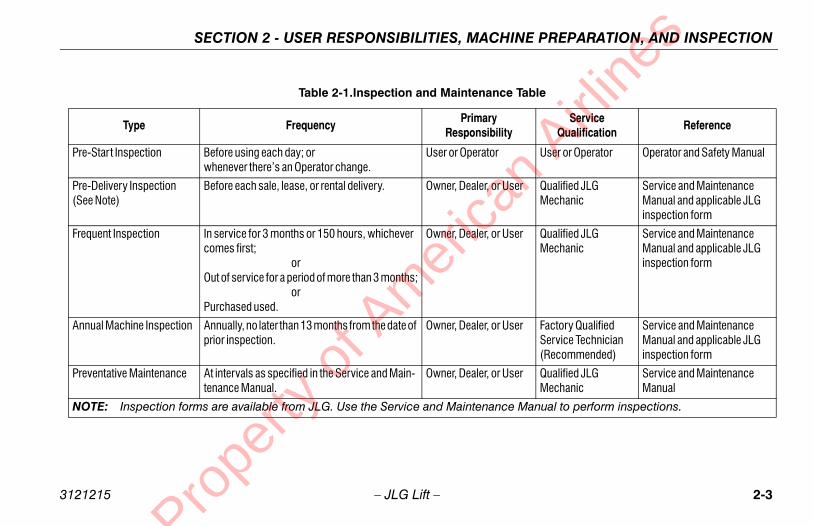
Table 2-1.Inspection and Maintena
Type FrequencyPrima
Respons
Pre-Start Inspection Before using each day; or whenever there’s an Operator change.
User or Operat
Pre-Delivery Inspection (See Note)
Before each sale, lease, or rental delivery. Owner, Dealer,
Frequent Inspection In service for 3 months or 150 hours, whichever comes first; orOut of service for a period of more than 3 months; orPurchased used.
Owner, Dealer,
Annual Machine Inspection Annually, no later than 13 months from the date of prior inspection.
Owner, Dealer,
Preventative Maintenance At intervals as specified in the Service and Main-tenance Manual.
Owner, Dealer,
NOTE: Inspection forms are available from JLG. Use the Service and Mainten
Prope
rty o
f Am
eric

SECTION 2 - USER RESPONSIBILITIES, MACHINE PREPARATION, AND INSPECTION
2-4 3121215
Pre stic only) is enclosed in the weather resistante container.
-Around” Inspection – Refer to Figure 2-2. thru 2-4.
y – Charge as required.
ombustion Engine Powered Machines) – Add the fuel as necessary.
ulic Oil – Check the hydraulic oil level. Ensurelic oil is added as required.
on Check – Once the “Walk-Around” Inspectionplete, perform a functional check of all systems ina free of overhead and ground level obstructions.o Section 4 for more specific instructions.
DOES NOT OPERATE PROPERLY, TURN OFF THEIATELY! REPORT THE PROBLEM TO THE PROPERERSONNEL. DO NOT OPERATE THE MACHINE UNTILAFE FOR OPERATION.
an A
irline
s
– JLG Lift –
-Start InspectionThe Pre-Start Inspection should include each of the follow-ing:
1. Cleanliness – Check all surfaces for leakage (oil, fuel,or battery fluid) or foreign objects. Report any leakage tothe proper maintenance personnel.
2. Structure - Inspect the machine structure for dents,damage, weld or parent metal cracks or other discrep-ancies.
3. Decals and Placards – Check all for cleanliness andlegibility. Make sure none of the decals and placards aremissing. Make sure all illegible decals and placards arecleaned or replaced.
4. Operators and Safety Manuals – Make sure a copy ofthe Operator and Safety Manual, EMI Safety Manual(Domestic only), and ANSI Manual of Responsibilities
(Domestorag
5. “WalkFigure
6. Batter
7. Fuel (Cproper
8. Hydrahydrau
9. Functiis coman areRefer t
IF THE MACHINEMACHINE IMMEDMAINTENANCE PIT IS DECLARED S
Parent Metal Crack Weld Crack
Prope
rty o
f Am
eric

CHINE PREPARATION, AND INSPECTION
2-5
ise, extend, retract, and lower the Upper Boom.heck for smooth operation.
tower boom does not rest on stop with machine in theowed position, this indicates upright is out of plumb.
lescope boom IN and OUT several cycles at variousgrees of elevation lengths. Check for smooth tele-ope operation.
ing turntable to LEFT and RIGHT a minimum of 45grees. Check for smooth motion.
heck the chassis out of level indicator located on theatform control console by driving, with the machine invel position, up a suitable ramp of at least 6° slope.heck the out of level alarm, with the machine on themp, raise the upper boom until it is parallel with theassis. DO NOT RAISE ABOVE THE PARALLEL POSI-ON. If the light does not illuminate, return the machine a level surface, shut down the machine, and contact aalified technician before resuming operation.
r units equipped with optional tilt cutout, verify that theive function is cutout when the boom is elevated andt alarm is activated.
an A
irline
s
SECTION 2 - USER RESPONSIBILITIES, MA3121215 – JLG Lift –
Function CheckA functional check of all systems should be performed, oncethe walk-around inspection is complete, in an area free ofoverhead and ground level obstructions. First, using theground controls, check all functions controlled by the groundcontrols. Next, using the platform controls, check all func-tions controlled by the platform controls.
TO AVOID SERIOUS INJURY, DO NOT OPERATE MACHINE IF ANY CON-TROL LEVERS OR TOGGLE SWITCHES CONTROLLING PLATFORMMOVEMENTS DO NOT RETURN TO THE OFF POSITION WHENRELEASED.
TO AVOID A COLLISION AND INJURY IF PLATFORM DOES NOT STOPWHEN A CONTROL SWITCH OR LEVER IS RELEASED, REMOVE FOOTFROM FOOTSWITCH OR USE EMERGENCY STOP TO STOP MACHINE.
1. Check boom limit switches. Raise and lower the LowerBoom. Check for smooth operation.
NOTE: Perform checks from ground controls first, then from plat-form controls.
2. RaC
3. If st
4. Tedesc
5. Swde
6. CplleCrachTItoqu
Fodrtil
Prope
rty o
f Am
eric

SECTION 2 - USER RESPONSIBILITIES, MACHINE PREPARATION, AND INSPECTION
2-6 3121215
DO NOF TNOT
FOOATE SWIBOT
FOOTION
tswitch depressed, operate LIFT and hold control. foot from footswitch, motion should stop. If itt, shut down machine and contact a qualified ser-nician.
the GROUND/PLATFORM SELECT switch toND. Platform controls should not operate.
GROUND/PLATFORM SELECT switch to OFF.m/Ground controls should not operate.an
Airli
nes
– JLG Lift –
OT DRIVE ON GRADES WHICH EXCEED THE RATED GRADEABILITYHE MACHINE AS INDICATED ON THE SERIAL NUMBER PLATE. DO DRIVE ON SIDESLOPES WHICH EXCEED 5 DEGREES.
7. Check that platform self-leveling system functions prop-erly during raising and lowering of boom.
8. Check rotator for smooth operation and assure platformwill rotate 75 degrees in both directions from centerlineof boom.
9. Drive forward and reverse; check for proper operation.
10. Steer left and right; check for proper operation.
11. Footswitch.
TSWITCH MUST BE ADJUSTED SO THAT FUNCTIONS WILL OPER-WHEN PEDAL IS APPROXIMATELY AT ITS CENTER OF TRAVEL. IFTCH OPERATES WITHIN LAST 1/4" (6 MM) OF TRAVEL, TOP ORTOM, IT SHOULD BE ADJUSTED.
TSWITCH MUST BE DEPRESSED PRIOR TO ACTIVATING ANY FUNC- CONTROL, OTHERWISE THE FUNCTION WILL NOT WORK.
With fooRemovedoes novice tech
12. Place GROU
13. Place Platfor
Prope
rty o
f Am
eric

CHINE PREPARATION, AND INSPECTION
2-7
lature
1. Platform Control Console2. Platform3. Upper Boom4. Telescope Cylinder5. Master Cylinder6. Upper Upright7. Upper Lift Cylinder8. Mid Lift Cylinder9. Lower Boom10. Turntable11. Frame12. Steer Wheels13. Drive Wheels14. Battery Box15. Lower Lift Cylinder16. Lower Link17. Lower Upright18. Upper Link19. Mid Boom20. Slave Cylinder21. Footswitch
an A
irline
s
SECTION 2 - USER RESPONSIBILITIES, MA3121215 – JLG Lift –
Figure 2-1. Basic Nomenc
Prope
rty o
f Am
eric

SECTION 2 - USER RESPONSIBILITIES, MACHINE PREPARATION, AND INSPECTION
2-8 3121215
3, 456,7
20
1
724
2
heet 1 of 3
an A
irline
s
– JLG Lift –
89
10
1112
131510
19
7
10 10
23, 16
27 1421 2215
16 14
17, 18
Figure 2-2. Daily Walk-Around Inspection - S
Prope
rty o
f Am
eric

CHINE PREPARATION, AND INSPECTION
2-9
latform and Gate Assembly - Platform mounting pinsecure. Footswitch in good working order; not modi-ed, disabled or blocked; Bar slides freely.
latform & Ground Control Console - Switches andvers return to neutral and are properly secured,ecals/placards secure and legible, control markinggible.
otator - See Note.
ib - See Note.
ib Rotator - See Note.
oom Sections - See Note.
ll Hydraulic Cylinders - No visible damage; pivot pinsnd hydraulic hoses undamaged, not leaking.
imit Switches - See Note.
n - Sheet 2 of 3
an A
irline
s
SECTION 2 - USER RESPONSIBILITIES, MA3121215 – JLG Lift –
GeneralBegin the “Walk-Around Inspection” at Item 1, as noted onthe diagram. Continue to the right (counterclockwiseviewed from top) checking each item in sequence for theconditions listed in the “Walk-Around Inspection Checklist”.
TO AVOID POSSIBLE INJURY BE SURE MACHINE POWER IS OFFDURING "WALK-AROUND INSPECTION".
DO NOT OVERLOOK VISUAL INSPECTION OF CHASSIS UNDERSIDE.CHECKING THIS AREA MAY RESULT IN DISCOVERY OF CONDITIONSWHICH COULD CAUSE EXTENSIVE MACHINE DAMAGE.
NOTE: On each item, make sure there are no loose or missingparts, that they are securely fastened and that no visibledamage exists in addition to any other criteria men-tioned.
1. Psfi
2. Pledle
3. R
4. J
5. J
6. B
7. Aa
8. L
Figure 2-3. Daily Walk-Around Inspectio
Prope
rty o
f Am
eric

SECTION 2 - USER RESPONSIBILITIES, MACHINE PREPARATION, AND INSPECTION
2-1 3121215
ng and Latches - See Note.
ry Charger - See Note.
- See Note.
/Upright - No visible damage; All pins properlyed. Upright in vertical position. If Upright doesst on stop with machine in the stowed position,dicates upright is out of plumb.
terweight - See Note.
od Ends and Steering Spindles - See Note. Tiend stubs locked.
al Descent Valve - See Note.
ol Valve - See Note.
e - See Note.
rm Pivot Pins - Properly secured.
heet 3 of 3
an A
irline
s
0 – JLG Lift –
9. Drive Axle and Motor - See Note.
10. Wheel/Tire Assembly - No loose or missing lug nuts.Inspect for worn tread, cuts, tears or other discrepan-cies. Inspect wheels for damage and corrosion.
11. Swing Motor and Worm Gear - See Note.
12. Hydraulic Pump and Reservoir - Properly secured; novisible damage or hydraulic leaks. Recommendedhydraulic fluid level on dipstick (system shut down,boom in stowed position). Breather cap/dipsticksecure and working.
13. Turntable Bearing - No loose or missing hardware; novisible damage; evidence of proper lubrication. Noloose bolts or looseness between bearing and struc-ture.
14. Battery Compartment Right Side - Batteries haveproper electrolyte level; cables tight; no visible dam-age or corrosion.
15. Cowli
16. Batte
17. Valve
18. Boomsecurnot rethis in
19. Coun
20. Tie Rrod e
21. Manu
22. Contr
23. Fram
24. Platfo
Figure 2-4. Daily Walk-Around Inspection - S
Prope
rty o
f Am
eric
MACHINE CONTROLS AND INDICATORS
3-1
AND INDICATORS
ontrol Station
re 3-1. and Figure 3-2.)
en machine is shut down the Platform/Ground Selectitch and Emergency Stop must be positioned to OFF.
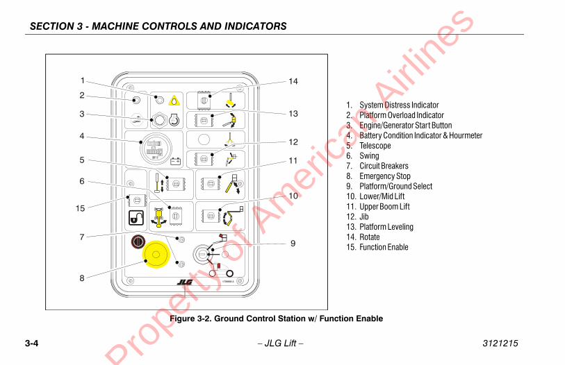
quipped, the Function Enable switch must be heldwn in order to operate Telescope, Lower Lift, Swing,in Lift, Jib Lift, Platform Level Override, and Platformtate functions.
stem Distress Indicator (If Equipped)
e system distress indicator lights to signify an abnor-al condition for the generator engine (high oil tempera-re or low oil pressure) or, on all electric machines, anectrical system fault.
e engine will automatically shut down under the follow- conditions:
h Oil Temperaturew Oil Pressuregine Overspeedervoltage
an A
irline
s
SECTION 3 -3121215 – JLG Lift –
SECTION 3. MACHINE CONTROLS
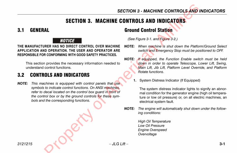
3.1 GENERAL
THE MANUFACTURER HAS NO DIRECT CONTROL OVER MACHINEAPPLICATION AND OPERATION. THE USER AND OPERATOR ARERESPONSIBLE FOR CONFORMING WITH GOOD SAFETY PRACTICES.
This section provides the necessary information needed tounderstand control functions.
3.2 CONTROLS AND INDICATORS
NOTE: This machines is equipped with control panels that usesymbols to indicate control functions. On ANSI machines,refer to decal located on the control box guard in front ofthe control box or by the ground controls for these sym-bols and the corresponding functions.
Ground C
(See Figu
NOTE: Whsw
NOTE: If edoMaRo
1. Sy
Thmtuel
NOTE: Thing
HigLoEnOv
Prope
rty o
f Am
eric

SECTION 3 - MACHINE CONTROLS AND INDICATORS
3-2 3121215
NOT
ope
es for extension and retraction of Upper Boompositioned to IN or OUT.
WING control switch provides 360 degrees non-uous turntable rotation. To activate SWING, posi-itch to LEFT or RIGHT.
Breakers
rcuit breakers open (pop out) to indicate a short orad somewhere on the machine.
/Emergency Stop Switch
position red mushroom shaped switch furnishes to PLATFORM/GROUND SELECT switch when out (on). When pushed in (off), power is shut offPLATFORM/GROUND SELECT switch.
an A
irline
s
– JLG Lift –
2. Platform Overload (If equipped)
Indicates the platform has been overloaded.
E: The engine will not start if the batteries are fully chargedor if the Generator Enable switch on the platform consoleis not in the on position.
3. Generator/Engine Start Button
The generator/engine start push-button switch allowsthe generator to be started manually to top-off the bat-tery charge. The generator will start automatically whenthe batteries reach a low-charge state and the GeneratorEnable switch on the platform console is in the on posi-tion.
4. Battery Indicator and Hourmeter
An hourmeter, installed in the upper portion of theGround Control Box, registers the amount of machineoperating time. The hourmeter registers up to 9,999.9hours and cannot be reset.
5. Telesc
Providwhen
6. Swing
The Scontintion sw
7. Circuit
The cioverlo
8. Power
A two-powerpulledto the
Prope
rty o
f Am
eric

MACHINE CONTROLS AND INDICATORS
3-3
tation
1. System Distress Indicator2. Platform Overload Indicator3. Engine/Generator Start Button4. Battery Condition Indicator & Hourmeter5. Telescope6. Swing7. Circuit Breakers8. Emergency Stop9. Platform/Ground Select10. Lower/Mid Lift11. Upper Boom Lift12. Jib13. Platform Leveling14. Rotate
an A
irline
s
SECTION 3 -3121215 – JLG Lift –
Figure 3-1. Ground Control S
Prope
rty o
f Am
eric
SECTION 3 - MACHINE CONTROLS AND INDICATORS
3-4 3121215
tion Enable
1. System Distress Indicator2. Platform Overload Indicator3. Engine/Generator Start Button4. Battery Condition Indicator & Hourmeter5. Telescope6. Swing7. Circuit Breakers8. Emergency Stop9. Platform/Ground Select10. Lower/Mid Lift11. Upper Boom Lift12. Jib13. Platform Leveling14. Rotate15. Function Enable
an A
irline
s
– JLG Lift –
Figure 3-2. Ground Control Station w/ Func
Prope
rty o
f Am
eric

MACHINE CONTROLS AND INDICATORS
3-5
ticulating Jib Boom (If equipped)
e Articulating Jib Boom control switch provides rais-g and lowering of the jib when positioned up or down.
THE PLATFORM LEVELING OVERRIDE FUNCTION FORLING OF THE PLATFORM. INCORRECT USE COULD CAUSE
CCUPANT TO SHIFT OR FALL. FAILURE TO DO SO COULDEATH OR SERIOUS INJURY.
atform Leveling Override
three position switch allows the operator to adjust thetomatic self leveling system. This switch is used tojust platform level in situations such as ascending/scending a grade.
tate
three position ROTATE control switch permits rotation the platform when positioned to left or right.
nction Enable
equipped, the enable switch must be held "DOWN" toable all boom controls when the engine is running.
an A
irline
s
SECTION 3 -3121215 – JLG Lift –
9. Platform/Ground Select Switch
A three position, key operated switch supplies power tothe platform control console when positioned to PLAT-FORM. With the switch key held in the GROUND posi-tion, power is shut off to platform and only groundcontrols are operable.
NOTE: With PLATFORM/GROUND SELECT switch in the centerposition, power is shut off to controls at both operatingstations.
10. Lower/Mid Boom Lift
Provides for raising and lowering of Lower Boom whenpositioned to UP or DOWN.
11. Upper Boom Lift
Provides for raising and lowering of Upper Boom whenpositioned to UP or DOWN.
12. Ar
Thin
ONLY USE SLIGHT LEVETHE LOAD/ORESULT IN D
13. Pl
A auadde
14. Ro
A of
15. Fu
If en
Prope
rty o
f Am
eric

SECTION 3 - MACHINE CONTROLS AND INDICATORS
3-6 3121215
Pla
(S
ONLSLIGTHERES
h-type HORN switch supplies electrical power toible warning device when pressed.
/Emergency Stop
position red mushroom shaped switch furnishes to PLATFORM Controls when pulled out (on).pushed in (off), power is shut off to the platformns.
about 2 seconds of pulling the switch out, thene will perform a diagnostic check of the variouscal circuits, and if everything is OK, the platformwill beep once. During this time the lights on thetor panel will also blink once as a bulb check.
ator Enable Control
enerator Enable control switch, when in the offn, allows the operator to prevent the generator from starting when using the machine indoors.in the on position (and the ground Emergencywitch on [pulled out]), the generator is enabled toatically start when the batteries need charged.
an A
irline
s
– JLG Lift –
tform Station
ee Figure 3-3.)
1. Posi-Track Control
Activating the Posi-Track switch allows the operator toengage positive traction for the time period pre-set in thecontroller. Posi-traction occurs by changing the drivemotors from a series to parallel arrangement, causingavailable power to be distributed evenly between thetwo drive wheels. The control system may also engagethe posi-track function automatically.
Y USE THE PLATFORM LEVELING OVERRIDE FUNCTION FORHT LEVELING OF THE PLATFORM. INCORRECT USE COULD CAUSE
LOAD/OCCUPANT TO SHIFT OR FALL. FAILURE TO DO SO COULDULT IN DEATH OR SERIOUS INJURY.
2. Platform Leveling Override
A three position switch allows the operator to adjust theautomatic self leveling system. This switch is used toadjust platform level in situations such as ascending/descending a grade.
3. Horn
A pusan aud
4. Power
A two-powerWhen functio
Withinmachielectrialarm indica
5. Gener
The GpositioengineWhen Stop Sautom
Prope
rty o
f Am
eric

MACHINE CONTROLS AND INDICATORS
3-7
winger Boom Lift
12. Platform Rotate13. Function Speed14. Main Lift/Swing
onsole
an A
irline
s
SECTION 3 -3121215 – JLG Lift –
1. Posi-Track2. Platform Leveling Override3. Horn4. Power/Emergency Stop
5. Generator Enable6. Lights7. Drive/Steer8. Telescope
9. Jib10. Jib S11. Low
Figure 3-3. Platform Control C
Prope
rty o
f Am
eric

SECTION 3 - MACHINE CONTROLS AND INDICATORS
3-8 3121215
8 7
15
6
5
iftte
13. Function Speed14. Main Lift/Swing15. Drive Orientation Override16. Soft Touch Override
e Orientation
an A
irline
s
– JLG Lift –
14 13 12 11 10 16 9
4321
1705170 A1702938
1. Posi-Track2. Platform Leveling Override3. Horn4. Power/Emergency Stop
5. Generator Enable6. Lights7. Drive/Steer8. Telescope
9. Jib10. Jib Swing11. Lower Boom L12. Platform Rota
Figure 3-4. Platform Control Console w/ Driv
Prope
rty o
f Am
eric

MACHINE CONTROLS AND INDICATORS
3-9
RIOUS INJURY, DO NOT OPERATE MACHINE IF ANY CON-RS OR TOGGLE SWITCHES CONTROLLING PLATFORMDO NOT RETURN TO THE OFF OR NEUTRAL POSITION
ASED.
lescope Control
e TELESCOPE control switch affords extension andtraction of the main boom when positioned to IN orUT.
b (If Equipped)
sh forward to lift up, pull back to lift down. Variable lifteed is using the Function Speed Control.
b Swing
sh toggle switch right to swing right, push left toing left.
wer Boom Lift
ovides for raising and lowering of Lower and Midom when positioned to UP or DOWN. Upper lift willt function when operating lower lift.
an A
irline
s
SECTION 3 -3121215 – JLG Lift –
6. Lights (If Equipped)
This switch operates control console panel lights andhead lights if the machine is so equipped.
7. Drive/Steer
The DRIVE controller provides for driving either forwardor backward when positioned to FORWARD orREVERSE. The controller is ‘ramped’ to allow infinitelyvariable drive speed between fast and slow.
Positioning the steer control thumb operated switchRIGHT or LEFT enables steering the machine to theright or left respectively.
NOTE: When lower boom is raised above horizontal, or the upperboom is raised approximately 16 inches (40.64 cm) aboveboom rest, the high drive function will automaticallyswitch to low drive. This also occurs when FunctionSpeed Control is clicked on creep.
NOTE: DRIVE control lever is spring-loaded and will automati-cally return to neutral (OFF) position when released.
TO AVOID SETROL LEVEMOVEMENT WHEN RELE
8. Te
ThreO
9. Ji
Pusp
10. Ji
Pusw
11. Lo
PrBono
Prope
rty o
f Am
eric

SECTION 3 - MACHINE CONTROLS AND INDICATORS
3-1 3121215
NOT
t and swing functions may be selected in combina-e handle features a round gate so that maximums reduced when multiple functions are selected.
ift will not function when operating upper lift.
rientation Override
the boom is swung over the rear tires or further indirection, the Drive Orientation indicator will illumi-hen the drive function is selected. Push and
e the switch, and within 3 seconds move theteer control to activate drive or steer. Before driv-
cate the black/white orientation arrows on bothassis and the platform controls and match thel direction arrow to the intended chassis direction.
uch Override Switch (If equipped)
witch enables the functions that were cut out byft Touch system to operate again at creep speed,g the operator to move the platform away fromstacle that caused the shutdown situation.
an A
irline
s
0 – JLG Lift –
12. Platform Rotate
The PLATFORM ROTATE control switch allows the oper-ator to rotate the basket to the left or right when posi-tioned to the desired direction.
13. Function Speed Control
Adjusts speed of Boom and Swing Functions. RotateCCW for slower speed and CW for faster speed. Toadjust Drive, Swing, and Main Lift to creep, turn knobfully CCW until it clicks.
E: Main Lift, Swing, and Drive control levers are spring-loaded and will automatically return to neutral (off) posi-tion when released.
14. Main Lift/Swing
The dual axis joystick is provided for main lift and swing.Push forward to lift up, pull backward to lift down. Moveright to swing right, move left to swing left. Moving thejoystick activates switches to provide the functionsselected. Proportional control of these functions can beattained by using the Function Speed knob.
NOTE: Main liftion. Thspeed i
Lower l
15. Drive O
When either nate wreleasDrive/Sing, lothe chcontro
16. Soft To
This sthe Soallowinthe ob
Prope
rty o
f Am
eric

MACHINE CONTROLS AND INDICATORS
3-11
tions.
ll Also Work at the Same Time:
ower Lift** Upper Lift** Telescope
ower Lift** Upper Lift** Telescope
No Telescope*
No Telescope
ower Lift** Upper Lift**
ower Lift** Upper Lift** Telescope
No No No
No No No
ted individually, due to sharing of oil.
ift or Swing) is being operated at full speed, due to sharing
an A
irline
s
SECTION 3 -3121215 – JLG Lift –
Table 3-1. Simultaneous Func
If This Function is Selected: These Functions Wi
Drive and Steer Swing L
Swing Drive and Steer L
Lower Lift Drive and Steer Swing*
Upper Lift Drive and Steer Swing
Telescope Drive and Steer Swing* L
Jib Articulate Drive and Steer Swing* L
Jib Swing Drive and Steer No
Platform Rotate Drive and Steer No
Note: Boom functions may be slower when selected with another function than when opera
* These functions may move very slowly (or not at all) if the first function selected (Lower Lof oil.
**Lower Lift and Upper Lift will not function simultaneously. Upper Lift always prevails.
Prope
rty o
f Am
eric

SECTION 3 - MACHINE CONTROLS AND INDICATORS
3-1 3121215
Pla
(S
NOT
rm Warning Light and Alarm
uminator indicates that the chassis is on a slope.rm will also sound when the chassis is on a slopee boom is above horizontal. If lit when boom is or extended, retract and lower to below horizontalposition machine so that it is level before continu-eration. If the boom is above horizontal and thene is on a slope, the tilt alarm warning light will illu- and an alarm will sound and CREEP is automati-ctivated.
LIGHT IS ILLUMINATED WHEN BOOM IS RAISED ORACT AND LOWER TO BELOW HORIZONTAL THEN
CHINE SO THAT IT IS LEVEL BEFORE EXTENDINGG BOOM ABOVE HORIZONTAL.
an A
irline
s
2 – JLG Lift –
tform Control Indicator Panel
ee Figure 3-5., Platform Control Indicator Panel)
E: The platform control indicator panel uses different shapedsymbols to alert the operator to different types of opera-tional situations that could arise. The meaning of thosesymbols are explained below.
1. Tilt Ala
This illAn alaand thraisedthen reing opmachiminatecally a
IF TILT WARNINGEXTENDED, RETRREPOSITION MABOOM OR RAISIN
Indicates a potentially hazardous situation, whichif not corrected, could result in serious injury ordeath. This indicator will be red.
Indicates an abnormal operating condition,which if not corrected, may result in machineinterruption or damage. This indicator will be yel-low.
Indicates important information regarding theoperating condition, i.e. procedures essential forsafe operation. This indicator will be green withthe exception of the capacity indicator which willbe green or yellow depending upon platformposition.
Prope
rty o
f Am
eric

MACHINE CONTROLS AND INDICATORS
3-13
1704239 E
+-
1001110226A
+-
9 6
543 82
TiltPlatform OverloadSystem DistressPosi-TrackEnable
6. Low Battery7. Creep8. Drive Orientation Override9. Soft Touch Indicator
ure 3-6. Platform Control Indicator Panel w/Drive Orientation
an A
irline
s
SECTION 3 -3121215 – JLG Lift –
1. Tilt2. Platform Overload3. System Distress4. Posi-Track
5. Enable6. Low Battery7. Creep
Figure 3-5. Platform Control Indicator Panel
7
1
1.2.3.4.5.
Fig
Prope
rty o
f Am
eric

SECTION 3 - MACHINE CONTROLS AND INDICATORS
3-1 3121215
e batteries are nearly depleted, and should bearged very soon to prevent having the machine
op at an inconvenient place.
ere is some other fault in one of the circuits. If sotermine the cause by counting the flash code, amber of flashes followed by a pause followed byother number of flashes, and refer to the serviceanual.
ine will automatically shut down under the follow-ditions:
gine Oil Temperaturegine Oil PressureOverspeedtor Overvoltage
rack Indicator.
dicator lights to show that posi-traction is operat-
an A
irline
s
4 – JLG Lift –
2. Platform Overload (If equipped)
Indicates the platform has been overloaded.
3. System Distress Indicator.
The system distress indicator lights to signify an abnor-mal condition for the generator engine (high oil tempera-ture or low oil pressure) or, on all electric machines, anelectrical system fault.
The four likely causes of a system fault are:
a. The seven second enable time has been allowed tolapse or a function was selected before depressingthe footswitch. The system reads this condition as afault, just as it would if the footswitch were jammedin the depressed position or a function switch werestuck in the on position. Re-depress the footswitchto power the controls and extinguish the light.
b. The maximum power limit has been reached andthe machine is not moving. This could happenwhen the machine is stuck or when attempting totravel over rough terrain or on steep grades whichexceed the rated gradeability of the machine. Thiscondition is comparable to stalling the engine byasking i t to provide more power than it wasdesigned to do.
c. Thchst
d. Thdenuanm
NOTE: The enging con
High EnLow EnEngine Genera
4. Posi-T
This ining.
Prope
rty o
f Am
eric

MACHINE CONTROLS AND INDICATORS
3-15
w Battery Indicator
dicates the batteries are low and need to be charged.
an A
irline
s
SECTION 3 -3121215 – JLG Lift –
5. Enable Indicator/Footswitch
To operate any function, the footswitch must bedepressed and the function selected within seven sec-onds. The enable indicator shows that the controls areenabled. If a function is not selected within seven sec-onds, or if a seven second lapse between ending onefunction and beginning the next function, the enablelight will go out and the footswitch must be released anddepressed again to enable the controls.
Releasing the footswitch removes power from all con-trols and applies the drive brakes.
TO AVOID SERIOUS INJURY, DO NOT REMOVE, MODIFY OR DISABLETHE FOOTSWITCH BY BLOCKING OR ANY OTHER MEANS.
FOOTSWITCH MUST BE ADJUSTED IF FUNCTIONS ACTIVATE WHENSWITCH ONLY OPERATES WITHIN LAST 1/4" OF TRAVEL, TOP OR BOT-TOM.
6. Lo
In
Prope
rty o
f Am
eric

SECTION 3 - MACHINE CONTROLS AND INDICATORS
3-1 3121215
uch Indicator (If Equipped)
illuminated (Yellow) the Soft Touch bumper ist an object. All controls are disabled until thee button is pushed, at which time controls arein the Creep mode.
an A
irline
s
6 – JLG Lift –
7. Creep Speed Indicator
When the Function Speed Control is turned to the creepposition, the indicator acts as a reminder that all func-tions are set to the slowest speed.
8. Drive Orientation Indicator
When the boom is swung beyond the rear drive tires orfurther in either direction, the Drive Orientation indicatorwill illuminate when the drive function is selected. This isa signal for the operator to activate the Drive OrientationOverride Switch and verify the drive control direction iscorrect.
9. Soft To
When againsoverridactive
Prope
rty o
f Am
eric
SECTION 4 - MACHINE OPERATION
4-1
PERATION
ERATING CHARACTERISTICS AND ITATIONS
esom can be raised above horizontal with or without any platform, if:
achine is positioned on a smooth, firm and level sur-ce.
ad is within manufacturers rated design capacity.
l machine systems are functioning properly.
oper tire pressure.
achine is as originally equipped from JLG.an
Airli
nes
3121215 – JLG Lift –
SECTION 4. MACHINE O
4.1 DESCRIPTIONThis machine is a self-propelled hydraulic personnel liftequipped with a work platform on the end of an elevatingand rotating boom.
The primary operator control station is in the platform. Fromthis control station, the operator can drive and steer themachine in both forward and reverse directions. The opera-tor can raise or lower the upper or lower boom or swing theboom to the left or right. Standard boom swing is 360 degreenon-continuous left and right of the stowed position. Themachine has a Ground Control Station which will overridethe Platform Control Station. Ground Controls operate Upperand Lower Boom Lift and Swing, and are to be used in anemergency to lower the platform to the ground should theoperator in the platform be unable to do so.
4.2 OPLIM
CapacitiThe boload in
1. Mfa
2. Lo
3. Al
4. Pr
5. M
Prope
rty o
f Am
eric

SECTION 4 - MACHINE OPERATION
4-2 3121215
Sta
TO MACFAC
R OPERATION
gency Stop/Emergency Stop switch, when pulled out (on),attery power for all machine functions. The switchpushed in (off) when recharging the batteries or machine overnight.
ped with the optional on-board generator, thency Stop switch must be left on (pulled out) tor automatic charging of the batteries.
out 2 seconds of pulling the switch out, theill perform a diagnostic check of the various elec-ts, and if everything is OK, the platform alarm will. During this time the lights on the indicator panelnk once as a bulb check.
an A
irline
s
– JLG Lift –
bilityMachine stability is based on two positions which are calledFORWARD and BACKWARD stability. The machines positionof least FORWARD stability is shown in Figure 4-1., Positionof Least Forward Stability, and its position of least BACK-WARD stability is shown in Figure 4-2., Position of LeastBackward Stability.
AVOID FORWARD OR BACKWARD TIPPING, DO NOT OVERLOADHINE OR OPERATE THE MACHINE ON AN OUT-OF-LEVEL SUR-E.
4.3 MOTO
Power/EmerThe Powerprovides bshould be parking the
NOTE: If equipEmergeallow fo
Within abmachine wtrical circuibeep oncewill also bli
Prope
rty o
f Am
eric

SECTION 4 - MACHINE OPERATION
4-3
ard Stability
MACHINE WILL "TIP OVER" IN THISDIRECTION IF OPERATED ON AN
OUT-OF-LEVEL SURFACE
BOOMEXTENDED
an A
irline
s
3121215 – JLG Lift –
Figure 4-1. Position of Least Forw
FLYFULLY
UPPER BOOMHORIZONTAL
TOWER AND MIDBOOM AT
33 DEGREES
Prope
rty o
f Am
eric

SECTION 4 - MACHINE OPERATION
4-4 3121215
Fig
ure
4-2.
Po
sitio
n o
f Le
ast B
ackw
ard
Sta
bili
ty
LOW
ER B
OOM
FULL
Y EL
EVAT
ED
an A
irline
s
– JLG Lift –
MID
BOO
MFU
LLY
ELEV
ATED
UPPE
R BO
OMFU
LLY
ELEV
ATED
AND
RETR
ACTE
D
PLAT
FORM
ROTA
TED
90 D
EGRE
ES
MAC
HINE
WIL
L "T
IP O
VER"
IN T
HIS
DIRE
CTIO
N IF
OPE
RATE
D ON
AN
OUT-
OF-L
EVEL
SUR
FACE
Prope
rty o
f Am
eric

SECTION 4 - MACHINE OPERATION
4-5
AVELING (DRIVING)
en lower boom is raised above horizontal, or the upperom is raised approximately 16 inches (40.6 cm) aboveom rest, the high drive function will automatically be in drive.
INE IS OPERATED AT A VERY SLOW SPEED OR STALLEDBING A GRADE OF 20% OR GREATER, DRIVE FUNCTION REMOVE FOOT FROM FOOT-SWITCH, AND DEPRESSH TO RESET.
IVE WITH BOOM ABOVE HORIZONTAL EXCEPT ON AM AND LEVEL SURFACE.
OSS OF TRAVEL CONTROL OR “TIP OVER” ON GRADESOPES, DO NOT DRIVE MACHINE ON GRADES EXCEEDINGIFIED ON THE SERIAL NUMBER PLATE.
E ON SIDESLOPES WHICH EXCEED 5 DEGREES.
ERRAIN FEATURES WHICH COULD CAUSE THE MACHINE.
an A
irline
s
3121215 – JLG Lift –
Platform/Ground Select SwitchThe Platform/Ground Select switch directs battery power tothe desired control station when the POWER/EMERGENCYSTOP switch is pulled out (on). With the switch held in theGROUND position battery power is supplied to the groundcontrol station. When the switch is in the PLATFORM posi-tion, battery power is supplied to the platform control station.
Motor Activation
FOOTSWITCH MUST BE DEPRESSED PRIOR TO ACTIVATING ANYFUNCTION, OTHERWISE FUNCTION WILL NOT OPERATE.
The motor becomes activated and operates the desiredfunction when the Emergency Stop switch is pulled out (on),the Platform/Ground select switch is in the appropriate posi-tion and the Footswitch is depressed.
IF A MOTOR MALFUNCTION NECESSITATES UNSCHEDULED SHUT-DOWN, DETERMINE AND CORRECT CAUSE BEFORE RESUMING ANYOPERATION.
4.4 TR
NOTE: Whbobolow
IF THE MACHWHEN CLIMWILL STOP.FOOTSWITC
DO NOT DRSMOOTH, FIR
TO AVOID LAND SIDE SLTHOSE SPEC
DO NOT DRIV
AVOID ANY TTO TIPOVER
Prope
rty o
f Am
eric

SECTION 4 - MACHINE OPERATION
4-6 3121215
USETIMEING TION
BEFDRIVCONMOT
Tra
FOOFUN
n Drive controller to FORWARD or REVERSE asd. Angle of controller will determine travel speed.
ine is equipped with a Drive Orientation Indicator. light on the platform control console indicatesom is swung beyond the rear drive tires and theay Drive/Steer in the opposite direction from the
t of the controls. If the indicator is illuminated, Drive function in the following manner:
the black and white direction arrows on both plat-ontrol panel and the chassis to determine the on the machine will travel.
nd release the Drive Orientation Override switch. 3 seconds, slowly move the Drive control toward ow matching the intended direction of machine The indicator light will flash during the 3 second l until the drive function is selected.
INGotswitch, position thumb switch on Drive/Steer
o RIGHT for steering right, or to LEFT for steering
an A
irline
s
– JLG Lift –
EXTREME CAUTION WHEN DRIVING IN REVERSE AND AT ALLS WHEN DRIVING WITH PLATFORM ELEVATED AND WHEN DRIV-WITH ANY PART OF MACHINE WITHIN 6 FEET OF ANY OBSTRUC-.
ORE DRIVING, MAKE SURE BOOM IS POSITIONED OVER REARE AXLE. IF BOOM IS OVER STEER WHEELS, STEER AND DRIVETROLS WILL MOVE IN OPPOSITE DIRECTIONS TO MACHINEION.
veling Forward and Reverse
TSWITCH MUST BE DEPRESSED PRIOR TO ACTIVATING ANYCTION, OTHERWISE FUNCTION WILL NOT OPERATE.
1. If machine is shut down, pull out Emergency Stop atGround Controls and place Platform/Ground Selectswitch to PLATFORM.
2. At Platform Controls, pull out Emergency Stop switchand activate footswitch.
3. Positiodesire
This machThe yellowthat the bomachine mmovemenoperate the
1. Matchform cdirecti
2. Push aWithinthe arrtravel.interva
4.5 STEERDepress focontroller tleft.
Prope
rty o
f Am
eric

SECTION 4 - MACHINE OPERATION
4-7
From Positions Above Ground Level loading weight to platform above ground level:
etermine what the total weight will be after additionaleight is loaded (personnel, tools and supplies).
total weight in platform will be 500 LBS. (227 kg forSI markets and 230 kg for CE and Australia markets)
less, proceed with adding weight.an A
irline
s
3121215 – JLG Lift –
4.6 PLATFORM
Loading From Ground Level1. Position chassis on a smooth, firm and level surface.
2. If total load (personnel, tools and supplies) is 500 LB.(227 kg for ANSI markets and 230 kg for CE and Austra-lia markets) or less, distribute load uniformly on platformfloor and proceed to work position.
Loading Before
1. Dw
2. If ANor
Prope
rty o
f Am
eric

SECTION 4 - MACHINE OPERATION
4-8 3121215
an A
irline
s
– JLG Lift –
Figure 4-3. Grade and Side Slopes
Prope
rty o
f Am
eric
SECTION 4 - MACHINE OPERATION
4-9
g
epress footswitch to rotate Jib and platform to the left,B SWING control switch is positioned to the LEFT andld until desired position is reached.
epress footswitch to rotate Jib and platform to theht, JIB SWING control switch is positioned to theGHT and held until desired position is reached.an
Airli
nes
3121215 – JLG Lift –
Platform Level Adjustment1. Leveling UP. Depress footswitch to raise platform, posi-
tion PLATFORM/LEVEL control switch UP and hold untilplatform is level.
2. Leveling DOWN. Depress footswitch to lower platform,position PLATFORM/LEVEL control switch to DOWNand hold until platform is level.
ONLY USE THE PLATFORM LEVELING OVERRIDE FUNCTION FORSLIGHT LEVELING OF THE PLATFORM. INCORRECT USE COULDCAUSE THE LOAD/OCCUPANT TO SHIFT OR FALL. FAILURE TO DO SOCOULD RESULT IN DEATH OR SERIOUS INJURY.
Platform Rotation1. Depress footswitch to rotate platform to the left, PLAT-
FORM ROTATE control switch is positioned to the LEFTand held until desired position is reached.
2. Depress footswitch to rotate platform to the right, PLAT-FORM ROTATE control switch is positioned to theRIGHT and held until desired position is reached.
Jib Swin
1. DJIhe
2. DrigRI
Prope
rty o
f Am
eric
SECTION 4 - MACHINE OPERATION
4-1 3121215
4.7
A REWHISLOLIGH
DO CHADEGING,
TO ARAISTHERAIS
TRAGRAPLA
TO CONMOV
.
LISION AND INJURY IF PLATFORM DOES NOT STOPL SWITCH OR LEVER IS RELEASED, REMOVE FOOTCH OR USE EMERGENCY STOP SWITCH TO STOP
e Boom
otswitch to swing boom, with footswitch activated,ING control switch to RIGHT or LEFT for direc-
.
THE BOOM MAKE SURE THERE IS AMPLE ROOMO CLEAR SURROUNDING WALLS, PARTITIONS AND
Lowering the Lower and Mid Boom
otswitch to raise or lower the Lower and Mid footswitch activated, position Lower Boom Lift
P or DOWN as desired.
an A
irline
s
0 – JLG Lift –
BOOM
D TILT WARNING LIGHT IS LOCATED ON THE CONTROL CONSOLECH LIGHTS WHEN THE CHASSIS IS ON A 5 DEGREE OR GREATERPE. DO NOT SWING OR RAISE BOOM ABOVE HORIZONTAL WHENT IS LIT.
NOT DEPEND ON TILT ALARM AS A LEVEL INDICATOR FOR THESSIS. TILT ALARM INDICATES CHASSIS IS ON A SEVERE SLOPE (5REE OR GREATER). CHASSIS MUST BE LEVEL BEFORE SWING- OR RAISING BOOM ABOVE HORIZONTAL.
VOID UPSET IF RED TILT WARNING LIGHT LIGHTS WHEN BOOM ISED ABOVE HORIZONTAL, LOWER PLATFORM TO GROUND LEVEL.
N REPOSITION MACHINE SO THAT CHASSIS IS LEVEL BEFOREING BOOM.
VELING WITH BOOM BELOW HORIZONTAL IS PERMITTED ONDES NOT EXCEEDING THOSE SPECIFIED ON THE SERIAL NUMBERTE.
AVOID SERIOUS INJURY, DO NOT OPERATE MACHINERY IF ANYTROL LEVER OR TOGGLE SWITCH CONTROLLING PLATFORMEMENT DOES NOT RETURN TO THE ‘OFF’ OR NEUTRAL POSITION
WHEN RELEASED
TO AVOID A COLWHEN A CONTROFROM FOOTSWITTHE MACHINE.
Swinging th
Depress foposition SWtion desired
WHEN SWINGINGFOR THE BOOM TEQUIPMENT.
Raising and
Depress foBoom, withswitch to U
Prope
rty o
f Am
eric

SECTION 4 - MACHINE OPERATION
4-11
nly Operating Mode
achine will operate in the battery only mode when theng two conditions apply:
round Control EMS is pulled out, and:
e switch on the platform control console is in the Off Disable position.
mode the machine will operate as a conventional bat-erated unit. The batteries can be used until they are
scharged.
Charge) Operating Mode
nerator will operate in manual mode always when theng three conditions apply.
round Control EMS is pulled out, and:
e switch on the platform control console is in the On Enable position and:
e Manual Charge push button is activated.
tion of the Manual Charge button will start the engineitiate the charging cycle even if the batteries ared above the level of automatic start. The operator can the charge cycle to charge the batteries to the maxi-
an A
irline
s
3121215 – JLG Lift –
Raising and Lowering the Upper Boom
Depress footswitch to raise or lower the Upper Boom, withfootswitch activated, position Upper Boom Lift switch to UPor DOWN until desired height is reached.
4.8 GENERATOR
The machine is equipped with an engine powered DC generatorconnected in parallel to the 48V DC battery bank.
Automatic Operating Mode
The generator will operate in automatic mode always whenthe following two conditions apply.
1. Ground Control EMS is pulled out (on), and:
2. The Generator Enable switch on the platform controlconsole is in the On or Enable position.
When the above conditions apply, the generator’s controllerwill monitor status of the batteries, will turn on automaticallywhen the battery voltage drops as a result of discharge andwill turn off when batteries are fully charged.
Battery O
The mfollowi
1. G
2. Thor
In thistery opfully di
Manual (
The gefollowi
1. G
2. Thor
3. Th
Activaand inchargeinitiate
Prope
rty o
f Am
eric

SECTION 4 - MACHINE OPERATION
4-1 3121215
4.9
INE FUNCTION SPEEDSon Speed Control affects the speed of boom func-r Lift, Telescope, and Rotate. Turn the control CWe function speed or CCW to decrease functionen in the CCW maximum position, Drive is placedeed.
DOWN AND PARK
arking battery powered units overnight, batteriesbe charged in accordance with instructions in 2 to ensure readiness for following workday.
machines are equipped with a static strap due tolectricity build-ups. Strap is located under rear ofe chassis.
wn and park the machine, the procedures are as
achine to a reasonably well protected area.
boom is lowered over rear drive axle.
own Emergency Stop at Platform Controls.
an A
irline
s
2 – JLG Lift –
mum level. The charging cycle will include finishing phasesimilar to conventional chargers.
INVERTERThe inverter converts 48 VDC to 110 VAC to allow operationof power tools from the machine’s batteries.
• The inverter is operational when the emergency stopswitch is pulled out.
• The machine and inverter can be operated at the sametime.
• The inverter will shut off at approximately 42 VDC and stayoff until the emergency stop switch is recycled. It will oper-ate again until voltage drops to 42 VDC.
• The machine will operate down to 36 VDC.
• The inverter will shut down if the high temperature lightindicated overheating. It will automatically turn back onwhen cooled.
• The overload light indicates an output wiring short circuitor a load that is too large for the rating of the inverter.
4.10 MACHThe Functitions Loweto increasspeed. Whin creep sp
4.11 SHUT
NOTE: When pshould Section
NOTE: Electricstatic emachin
To shut dofollows:
1. Drive m
2. Ensure
3. Shut d
Prope
rty o
f Am
eric

SECTION 4 - MACHINE OPERATION
4-13
CHINE LIFTING AND TIE DOWN
heck Serial Number Plate, call JLG Industries, or weighe individual unit to obtain GVW.
ace the boom in the stowed position.
move all loose items from the machine.
operly adjust the rigging to prevent damage to theachine and so the machine remains level.
ace the boom in the stowed position.
move all loose items from the machine.
cure the chassis and the platform using straps orains of adequate strength.
an A
irline
s
3121215 – JLG Lift –
4. Shut down Emergency Stop at Ground Controls. Posi-tion Platform/Ground Select switch to center OFF.
5. If necessary, cover Platform Controls to protect instruc-tion placards, warning decals and operating controlsfrom hostile environment.
4.12 BOOM SYNCHRONIZING PROCEDURE
NOTE: If the Lower Boom assembly does not fully lower:
1. Remove all personnel from the platform.
2. Pull the red knob located beside the main control valve.
3. From Ground Control, activate the lift control switch,raise Lower Boom 6 feet (1.8 m).
4. After raising Lower Boom, release the red knob.
5. Activate Lower Boom Down, fully lower boom.
6. Repeat step 1 thru 5 if necessary.
4.13 MA
Lifting
1. Cth
2. Pl
3. Re
4. Prm
Tie Down
1. Pl
2. Re
3. Sech
Prope
rty o
f Am
eric

SECTION 4 - MACHINE OPERATION
4-1 3121215
Li1.2.3.4.
an A
irline
s
4 – JLG Lift –
Figure 4-4. Lifting Chart
fting Instructions: Check Serial Number Plate, call JLG Industries, or weigh the individual unit to obtain GVW. Place the boom in the stowed position. Remove all loose items from the machine. Properly adjust the rigging to prevent damage to the machine and so the machine remains level.
Prope
rty o
f Am
eric
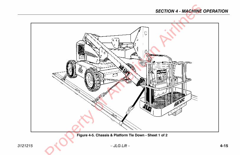
SECTION 4 - MACHINE OPERATION
4-15
- Sheet 1 of 2
an A
irline
s
3121215 – JLG Lift –
Figure 4-5. Chassis & Platform Tie Down
Prope
rty o
f Am
eric
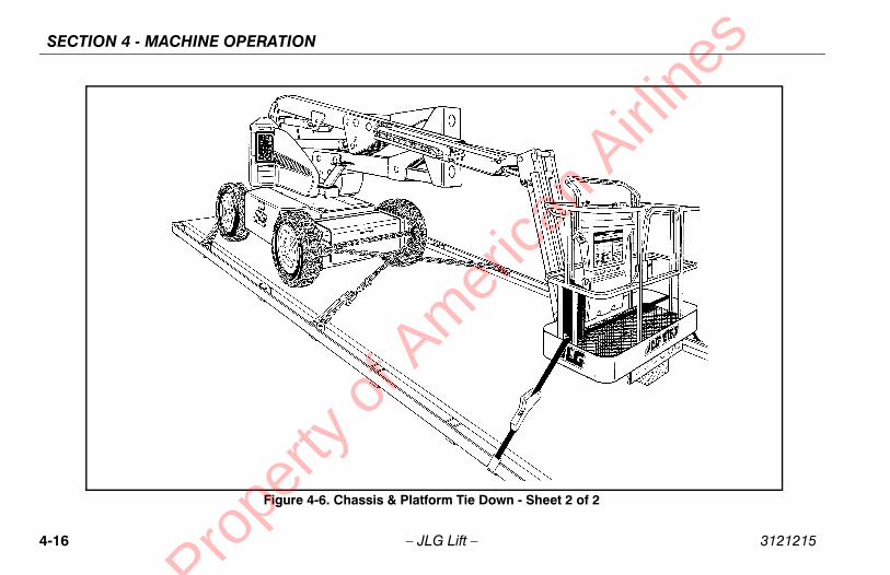
SECTION 4 - MACHINE OPERATION
4-1 3121215
heet 2 of 2
an A
irline
s
6 – JLG Lift –
Figure 4-6. Chassis & Platform Tie Down - S
Prope
rty o
f Am
eric

SECTION 4 - MACHINE OPERATION
4-17
of 3
an A
irline
s
3121215 – JLG Lift –
Figure 4-7. Decal Installation - Sheet 1
Prope
rty o
f Am
eric

SECTION 4 - MACHINE OPERATION
4-1 3121215
3
an A
irline
s
8 – JLG Lift –
Figure 4-8. Decal Installation - Sheet 2 of
Prope
rty o
f Am
eric
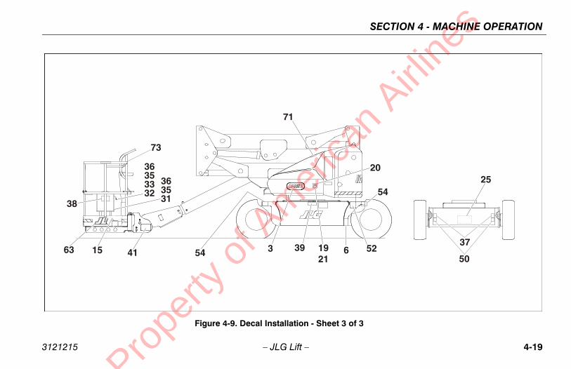
SECTION 4 - MACHINE OPERATION
4-19
of 3
an A
irline
s
3121215 – JLG Lift –
Figure 4-9. Decal Installation - Sheet 3
Prope
rty o
f Am
eric

SECTION 4 - MACHINE OPERATION
4-2 3121215
S/N 0300142589
Eng/CSA French0259495-13
Chinese/Eng
0259540-11
Spa/Portuguese0259499-13
- - - - - -
1703936 1703937 1703940
- - - - - -
1703930 1703931 1703934
1705514 - - - -
1700584 1700584 1700584
1706948 1706948 1706948
- - - - - -
1701504 1701504 1701504
1701642 1701642 1701642
1703924 1703925 1703928
- - - - - -
1701644 1701644 1701644
3251813 - - 3251813
an A
irline
s
0 – JLG Lift –
Table 4-1. E400A/E400AJP Decal Legend - Prior to
Item # ANSI0259301-16
CE/AusI0275070-6
Japanese0259536-11
Korean0259538-11
Eng/Lat. Spanish0259497-13
1 - - - - - - - - - -
2 1703805 - - 1703938 1703939 1703935
3 - - - - - - - - - -
4 1703798 1705822 1703932 1703933 1703929
5 - - - - - - - - - -
6 1700584 1700584 1700584 1700584 1700584
7 3252342 - - 1706948 1706948 1706948
8 - - - - - - - - - -
9 1701504 1701504 1701504 1701504 1701504
10 1701642 1701642 1701642 1701642 1701642
11 1703797 1705921 1703926 1703927 1703923
12 - - - - - - - - - -
13 1701644 1701644 1701644 1701644 1701644
14 3251813 - - - - - - - -
Prope
rty o
f Am
eric

SECTION 4 - MACHINE OPERATION
4-21
83 1703984 1703982 1703985
77 1704277 1704277 1704277
07 1704006 - - 1704008
- - - - - -
- - - - - -
43 3251243 - - 3251243
- - - - - -
91 1701691 1701691 1701691
4864 1001104864 1001104864 1001104864
01 1704000 - - 1704002
54 1704254 1704254 1704254
53 1704253 - - 1704253
54 1704452 1704419 1704453
31 1704431 1704431 1704431
r to S/N 0300142589
/nish7-13
Eng/CSA French0259495-13
Chinese/Eng
0259540-11
Spa/Portuguese0259499-13
an A
irline
s
3121215 – JLG Lift –
15 - - 1705828 1703980 1703981 17039
16 1704277 1704277 1704277 1704277 17042
17 - - - - - - - - 17040
18 - - - - - - - - - -
19 - - - - - - - - - -
20 - - - - - - - - 32512
21 - - - - - - - - - -
22 1701691 1701691 1701691 1701691 17016
23 1001104864 1001104864 1001104864 1001104864 100110
24 1702868 - - - - - - 17040
25 1704254 1704254 1704254 1704254 17042
26 1704253 - - 1704253 - - 17042
27 1704446 1706378 1704417 1704418 17044
28 1704431 1704431 1704431 1704431 17044
Table 4-1. E400A/E400AJP Decal Legend - Prio
Item # ANSI0259301-16
CE/AusI0275070-6
Japanese0259536-11
Korean0259538-11
EngLat. Spa025949
Prope
rty o
f Am
eric
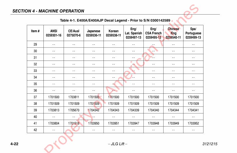
SECTION 4 - MACHINE OPERATION
4-2 3121215
- - - - - -
- - - - - -
- - - - - -
- - - - - -
- - - - - -
- - - - - -
- - - - - -
- - - - - -
1701500 1701500 1701500
1701509 1701509 1701509
1704340 1704344 1704341
- - - - - -
1703948 1703949 1703952
- - - - - -
S/N 0300142589
Eng/CSA French0259495-13
Chinese/Eng
0259540-11
Spa/Portuguese0259499-13
an A
irline
s
2 – JLG Lift –
29 - - - - - - - - - -
30 - - - - - - - - - -
31 - - - - - - - - - -
32 - - - - - - - - - -
33 - - - - - - - - - -
34 - - - - - - - - - -
35 - - - - - - - - - -
36 - - - - - - - - - -
37 1701500 1703811 1701500 1701500 1701500
38 1701509 1701509 1701509 1701509 1701509
39 1703813 1705670 1704342 1704343 1704339
40 - - - - - - - - - -
41 1703804 1701518 1703950 1703951 1703947
42 - - - - - - - - - -
Table 4-1. E400A/E400AJP Decal Legend - Prior to
Item # ANSI0259301-16
CE/AusI0275070-6
Japanese0259536-11
Korean0259538-11
Eng/Lat. Spanish0259497-13
Prope
rty o
f Am
eric

SECTION 4 - MACHINE OPERATION
4-23
- - - - - -
- - - - - -
- - - - - -
- - - - - -
65 1702265 1703988 1703991
- - - - - -
- - - - - -
00 1702300 1702300 1702300
- - - - - -
31 1702631 1702631 1702631
49 1707047 1707044 1707133
- - - - - -
- - - - - -
- - - - - -
r to S/N 0300142589
/nish7-13
Eng/CSA French0259495-13
Chinese/Eng
0259540-11
Spa/Portuguese0259499-13
an A
irline
s
3121215 – JLG Lift –
43 - - - - - - - - - -
44 - - - - - - - - - -
45 - - - - - - - - - -
46 - - - - - - - - - -
47 1702265 1705977 1702271 1703987 17022
48 - - - - - - - - - -
49 - - - - - - - - - -
50 1702300 1703814 1702300 1702300 17023
51 - - - - - - - - - -
52 1702631 1702631 1702631 1702631 17026
53 1707013 1705978 1707054 1707042 17070
54 - - - - - - - - - -
55 - - - - - - - - - -
56 - - - - - - - - - -
Table 4-1. E400A/E400AJP Decal Legend - Prio
Item # ANSI0259301-16
CE/AusI0275070-6
Japanese0259536-11
Korean0259538-11
EngLat. Spa025949
Prope
rty o
f Am
eric

SECTION 4 - MACHINE OPERATION
4-2 3121215
- - - - - -
- - - - - -
- - - - - -
- - - - - -
- - - - - -
- - - - - -
- - - - - -
1704252 - - 1706950
1707055 1707060 1707134
1701502 1701502 1701502
1701503 1701503 1701503
- - - - - -
- - - - - -
- - - - - -
S/N 0300142589
Eng/CSA French0259495-13
Chinese/Eng
0259540-11
Spa/Portuguese0259499-13
an A
irline
s
4 – JLG Lift –
57 - - - - - - - - - -
58 - - - - - - - - - -
59 - - - - - - - - - -
60 - - - - - - - - - -
61 - - - - - - - - - -
62 - - - - - - - - - -
63 - - - - - - - - - -
64 1706950 - - - - - - 1706950
65 1701645 1705978 1707059 1707058 1707056
66 1701502 1701502 1701502 1701502 1701502
67 1701503 1701503 1701503 1701503 1701503
68 - - - - - - - - - -
69 - - - - - - - - - -
70 - - - - - - - - - -
Table 4-1. E400A/E400AJP Decal Legend - Prior to
Item # ANSI0259301-16
CE/AusI0275070-6
Japanese0259536-11
Korean0259538-11
Eng/Lat. Spanish0259497-13
Prope
rty o
f Am
eric

SECTION 4 - MACHINE OPERATION
4-25
- - - - - -
- - - - - -
- - - - - -
- - - - - -
- - - - - -
- - - - - -
12 1704412 1704412 1704412
- - - - - -
85 1704885 1704885 1704885
r to S/N 0300142589
/nish7-13
Eng/CSA French0259495-13
Chinese/Eng
0259540-11
Spa/Portuguese0259499-13
an A
irline
s
3121215 – JLG Lift –
71 - - - - - - - - - -
72 - - - - - - - - - -
73 - - - - - - - - - -
74 - - - - - - - - - -
75 - - - - - - - - - -
76 - - - - - - - - - -
77 1704412 1704412 1704412 1704412 17044
78 1704830 - - - - - - - -
79 1704885 1704885 1704885 1704885 17048
Table 4-1. E400A/E400AJP Decal Legend - Prio
Item # ANSI0259301-16
CE/AusI0275070-6
Japanese0259536-11
Korean0259538-11
EngLat. Spa025949
Prope
rty o
f Am
eric

SECTION 4 - MACHINE OPERATION
4-2 3121215
142589 to Present
Eng/CSA French0259495-17
Chinese/Eng
0259540-14
Spa/Portuguese0259499-16
- - - - - -
1703936 1703937 1703940
- - - - - -
1703930 1703931 1703934
1705514 - - - -
1700584 - - - -
1706948 1706948 1706948
- - - - - -
1701504 1701504 1701504
1701642 1701642 1701642
1703924 1703925 1703928
- - - - - -
1701644 1701644 1701644
- - - - - -
an A
irline
s
6 – JLG Lift –
Table 4-2. E400A/E400AJP Decal Legend - S/N 0300
Item # ANSI0259301-22
CE/AusI0275070-7
Japanese0259536-14
Korean0259538-14
Eng/Lat. Spanish0259497-17
1 - - - - - - - - - -
2 1703805 - - 1703938 1703939 1703935
3 - - - - - - - - - -
4 1703798 1705822 1703932 1703933 1703929
5 - - - - - - - - - -
6 1700584 - - - - 1700584 - -
7 3252342 - - 1706948 1706948 1706948
8 - - - - - - - - - -
9 1701504 1701504 1701504 1701504 1701504
10 1701642 1701642 1701642 1701642 1701642
11 1703797 1705921 1703926 1703927 1703923
12 - - - - - - - - - -
13 1701644 1701644 1701644 1701644 1701644
14 - - - - - - - - - -
Prope
rty o
f Am
eric

SECTION 4 - MACHINE OPERATION
4-27
83 1703984 1703982 1703985
77 1704277 1704277 1704277
- - - - 1704008
- - - - - -
- - - - - -
43 3251243 - - 3251243
- - - - - -
91 1701691 1701691 1701691
4864 1001104864 1001104864 1001104864
01 1704000 - - 1704002
54 1704254 1704254 1704254
53 1704253 - - 1704253
54 1704452 1704419 1704453
31 1704431 1704431 1704431
300142589 to Present
/nish7-17
Eng/CSA French0259495-17
Chinese/Eng
0259540-14
Spa/Portuguese0259499-16
an A
irline
s
3121215 – JLG Lift –
15 - - 1705828 1703980 1703981 17039
16 1704277 1704277 1704277 1704277 17042
17 - - - - - - - - - -
18 - - - - - - - - - -
19 - - - - - - - - - -
20 - - - - - - - - 32512
21 - - - - - - - - - -
22 1701691 1701691 1701691 1701691 17016
23 1001104864 1001104864 1001104864 1001104864 100110
24 1702868 - - - - - - 17040
25 1704254 1704254 1704254 1704254 17042
26 1704253 - - 1704253 - - 17042
27 1704446 1706378 1704417 1704418 17044
28 1704431 1704431 1704431 1704431 17044
Table 4-2. E400A/E400AJP Decal Legend - S/N 0
Item # ANSI0259301-22
CE/AusI0275070-7
Japanese0259536-14
Korean0259538-14
EngLat. Spa025949
Prope
rty o
f Am
eric

SECTION 4 - MACHINE OPERATION
4-2 3121215
- - - - - -
- - - - - -
- - - - - -
- - - - - -
- - - - - -
- - - - - -
- - - - - -
- - - - - -
1701500 1701500 1701500
1701509 1701509 1701509
1704340 1704344 1704341
- - - - - -
1703948 1703949 1703952
- - - - - -
142589 to Present
Eng/CSA French0259495-17
Chinese/Eng
0259540-14
Spa/Portuguese0259499-16
an A
irline
s
8 – JLG Lift –
29 - - - - - - - - - -
30 - - - - - - - - - -
31 - - - - - - - - - -
32 - - - - - - - - - -
33 - - - - - - - - - -
34 - - - - - - - - - -
35 - - - - - - - - - -
36 - - - - - - - - - -
37 1701500 1703811 1701500 1701500 1701500
38 1701509 1701509 1701509 1701509 1701509
39 1703813 1705670 1704342 1704343 1704339
40 3252347 - - - - - - - -
41 1703804 1701518 1703950 1703951 1703947
42 - - - - - - - - - -
Table 4-2. E400A/E400AJP Decal Legend - S/N 0300
Item # ANSI0259301-22
CE/AusI0275070-7
Japanese0259536-14
Korean0259538-14
Eng/Lat. Spanish0259497-17
Prope
rty o
f Am
eric

SECTION 4 - MACHINE OPERATION
4-29
- - - - - -
- - - - - -
- - - - - -
- - - - - -
65 1702265 1703988 1703991
- - - - - -
- - - - - -
00 1702300 1702300 1702300
- - - - - -
1702631 - - - -
1818 1001121816 1001121823 1001121923
- - - - - -
- - - - - -
- - - - - -
300142589 to Present
/nish7-17
Eng/CSA French0259495-17
Chinese/Eng
0259540-14
Spa/Portuguese0259499-16
an A
irline
s
3121215 – JLG Lift –
43 - - - - - - - - - -
44 - - - - - - - - - -
45 - - - - - - - - - -
46 - - - - - - - - - -
47 1702265 1705977 1702271 1703987 17022
48 - - - - - - - - - -
49 - - - - - - - - - -
50 1702300 1703814 1702300 1702300 17023
51 - - - - - - - - - -
52 - - - - - - - - - -
53 1001121814 1705978 1001121821 1001121921 100112
54 - - - - - - - - - -
55 - - - - - - - - - -
56 - - - - - - - - - -
Table 4-2. E400A/E400AJP Decal Legend - S/N 0
Item # ANSI0259301-22
CE/AusI0275070-7
Japanese0259536-14
Korean0259538-14
EngLat. Spa025949
Prope
rty o
f Am
eric

SECTION 4 - MACHINE OPERATION
4-3 3121215
- - - - - -
- - - - - -
- - - - - -
- - - - - -
- - - - - -
- - - - - -
- - - - - -
1704252 - - 1706950
1001121803 1001121810 1001121920
1701502 1701502 1701502
1701503 1701503 1701503
- - - - - -
- - - - - -
- - - - - -
142589 to Present
Eng/CSA French0259495-17
Chinese/Eng
0259540-14
Spa/Portuguese0259499-16
an A
irline
s
0 – JLG Lift –
57 - - - - - - - - - -
58 - - - - - - - - - -
59 - - - - - - - - - -
60 - - - - - - - - - -
61 - - - - - - - - - -
62 - - - - - - - - - -
63 - - - - - - - - - -
64 1706950 - - - - - - 1706950
65 1001121801 1705978 1001121808 1001121918 1001121805
66 1701502 1701502 1701502 1701502 1701502
67 1701503 1701503 1701503 1701503 1701503
68 - - - - - - - - - -
69 - - - - - - - - - -
70 - - - - - - - - - -
Table 4-2. E400A/E400AJP Decal Legend - S/N 0300
Item # ANSI0259301-22
CE/AusI0275070-7
Japanese0259536-14
Korean0259538-14
Eng/Lat. Spanish0259497-17
Prope
rty o
f Am
eric

SECTION 4 - MACHINE OPERATION
4-31
- - - - - -
- - - - - -
- - - - - -
- - - - - -
- - - - - -
- - - - - -
12 1704412 1704412 1704412
- - - - - -
85 1704885 1704885 1704885
- - - - - -
10 1705429 1705430 1001113680
300142589 to Present
/nish7-17
Eng/CSA French0259495-17
Chinese/Eng
0259540-14
Spa/Portuguese0259499-16
an A
irline
s
3121215 – JLG Lift –
71 - - - - - - - - - -
72 - - - - - - - - - -
73 - - - - - - - - - -
74 - - - - - - - - - -
75 - - - - - - - - - -
76 - - - - - - - - - -
77 1704412 1704412 1704412 1704412 17044
78 1704830 - - - - - - - -
79 1704885 1704885 1704885 1704885 17048
80 - - - - - - - - - -
81 1705351 - - 1705426 1705427 17059
Table 4-2. E400A/E400AJP Decal Legend - S/N 0
Item # ANSI0259301-22
CE/AusI0275070-7
Japanese0259536-14
Korean0259538-14
EngLat. Spa025949
Prope
rty o
f Am
eric

SECTION 4 - MACHINE OPERATION
4-3 3121215
S/N 0300142589
Eng/French
0259494-15
Chinese0259539-13
Spa/Portuguese0259498-15
- - - - - -
1703936 1703937 1703940
- - - - - -
1703930 1703931 1703934
1705514 - - - -
1700584 1700584 1700584
1706948 1706948 1706948
- - - - - -
1701504 1701504 1701504
1701642 1701642 1701642
1703924 1703925 1703928
- - - - - -
1701644 1701644 1701644
3251813 - - 3251813
1703984 1703982 1703985
1704277 1704277 1704277
1704006 - - 1704008
an A
irline
s
2 – JLG Lift –
Table 4-3. M400A/M400AJ Decal Legend - Prior to
Item # ANSI0258973-18
CE/AusI0275069-6
Japanese0259535-13
Korean0259537-13
Eng/Spanish
0259496-15
1 - - - - - - - - - -
2 1703805 - - 1703938 1703939 1703935
3 - - - - - - - - - -
4 1703798 1705822 1703932 1703933 1703929
5 - - - - - - - - - -
6 1700584 1700584 1700584 1700584 1700584
7 1706948 - - 1706948 1706948 1706948
8 - - - - - - - - - -
9 1701504 1701504 1701504 1701504 1701504
10 1701642 1701642 1701642 1701642 1701642
11 1703797 1705921 1703926 1703927 1703923
12 - - - - - - - - - -
13 1701644 1701644 1701644 1701644 1701644
14 3251813 - - - - - - 3251813
15 - - 1705828 1703980 1703981 1703983
16 1704277 1704277 1704277 1704277 1704277
17 - - - - - - - - 1704007
Prope
rty o
f Am
eric

SECTION 4 - MACHINE OPERATION
4-33
- - - - - -
- - - - - -
43 3251243 3251243 3251243
- - - - - -
91 1701691 1701691 1701691
864 1001104864 1001104864 1001104864
01 1704000 1704000 1704002
54 1704254 1704254 1704254
53 1704253 - - 1704253
54 1704452 1704419 1704453
31 1704431 1704431 1704431
- - - - - -
- - - - - -
- - - - - -
- - - - - -
- - - - - -
- - - - - -
- - - - - -
r to S/N 0300142589
/sh6-15
Eng/French
0259494-15
Chinese0259539-13
Spa/Portuguese0259498-15
an A
irline
s
3121215 – JLG Lift –
18 - - - - - - - - - -
19 - - - - - - - - - -
20 - - - - - - - - 32512
21 - - - - - - - - - -
22 1701691 1701691 1701691 1701691 17016
23 1001104864 1001104864 1001104864 1001104864 1001104
24 1702868 - - - - - - 17040
25 1704254 1704254 1704254 1704254 17042
26 1704253 - - - - - - 17042
27 1704446 1706378 1704417 1704418 17044
28 1704431 1704431 1704431 1704431 17044
29 - - - - - - - - - -
30 - - - - - - - - - -
31 - - - - - - - - - -
32 - - - - - - - - - -
33 - - - - - - - - - -
34 - - - - - - - - - -
35 - - - - - - - - - -
Table 4-3. M400A/M400AJ Decal Legend - Prio
Item # ANSI0258973-18
CE/AusI0275069-6
Japanese0259535-13
Korean0259537-13
EngSpani
025949
Prope
rty o
f Am
eric

SECTION 4 - MACHINE OPERATION
4-3 3121215
- - - - - -
1701500 1701500 1701500
1701509 1701509 1701509
1704340 1704344 1704341
- - - - - -
1703948 1703949 1703952
- - - - - -
- - - - - -
- - - - - -
- - - - - -
- - - - - -
1702265 1703988 1703991
- - - - - -
- - - - - -
1702300 1702300 1702300
- - - - - -
1702631 1702631 1702631
1707047 1707044 1707133
S/N 0300142589
Eng/French
0259494-15
Chinese0259539-13
Spa/Portuguese0259498-15
an A
irline
s
4 – JLG Lift –
36 - - - - - - - - - -
37 1701500 1703811 1701500 1701500 1701500
38 1701509 1701509 1701509 1701509 1701509
39 1703813 1705670 1704342 1704343 1704339
40 - - - - - - - - - -
41 1703804 1701518 1703950 1703951 1703947
42 - - - - - - - - - -
43 - - - - - - - - - -
44 - - - - - - - - - -
45 - - - - - - - - - -
46 - - - - - - - - - -
47 1702265 1705977 1702271 1703987 1702265
48 - - - - - - - - - -
49 - - - - - - - - - -
50 1702300 1703814 1702300 1702300 1702300
51 - - - - - - - - - -
52 1702631 1702631 1702631 1702631 1702631
53 1707013 1705978 1707054 1707042 1707049
Table 4-3. M400A/M400AJ Decal Legend - Prior to
Item # ANSI0258973-18
CE/AusI0275069-6
Japanese0259535-13
Korean0259537-13
Eng/Spanish
0259496-15
Prope
rty o
f Am
eric

SECTION 4 - MACHINE OPERATION
4-35
- - - - - -
- - - - - -
- - - - - -
- - - - - -
- - - - - -
- - - - - -
- - - - - -
- - - - - -
- - - - - -
- - - - - -
50 1706950 - - 1706950
56 1707055 1707060 1707134
02 1701502 1701502 1701502
03 1701503 1701503 1701503
- - - - - -
- - - - - -
3687 1001093687 1001093687 1001093687
- - - - - -
r to S/N 0300142589
/sh6-15
Eng/French
0259494-15
Chinese0259539-13
Spa/Portuguese0259498-15
an A
irline
s
3121215 – JLG Lift –
54 - - - - - - - - - -
55 - - - - - - - - - -
56 - - - - - - - - - -
57 - - - - - - - - - -
58 - - - - - - - - - -
59 - - - - - - - - - -
60 - - - - - - - - - -
61 - - - - - - - - - -
62 - - - - - - - - - -
63 - - - - - - - - - -
64 1706950 - - - - - - 17069
65 1701645 1705978 1707059 1707058 17070
66 1701502 1701502 1701502 1701502 17015
67 1701503 1701503 1701503 1701503 17015
68 - - - - - - - - - -
69 - - - - - - - - - -
70 1704286 - - 1001093687 1001093687 100109
71 - - - - - - - - - -
Table 4-3. M400A/M400AJ Decal Legend - Prio
Item # ANSI0258973-18
CE/AusI0275069-6
Japanese0259535-13
Korean0259537-13
EngSpani
025949
Prope
rty o
f Am
eric

SECTION 4 - MACHINE OPERATION
4-3 3121215
- - - - - -
- - - - - -
- - - - - -
- - - - - -
- - - - - -
1704412 1704412 1704412
1704830 1704830 1704830
1704885 1704885 1704885
S/N 0300142589
Eng/French
0259494-15
Chinese0259539-13
Spa/Portuguese0259498-15
an A
irline
s
6 – JLG Lift –
72 - - - - - - - - - -
73 1702962 - - - - - - - -
74 - - - - - - - - - -
75 - - - - 1705084 1705084 - -
76 - - - - - - - - - -
77 1704412 1704412 1704412 1704412 1704412
78 1704830 1704830 1704830 1704830 1704830
79 1704885 1704885 1704885 1704885 1704885
Table 4-3. M400A/M400AJ Decal Legend - Prior to
Item # ANSI0258973-18
CE/AusI0275069-6
Japanese0259535-13
Korean0259537-13
Eng/Spanish
0259496-15
Prope
rty o
f Am
eric

SECTION 4 - MACHINE OPERATION
4-37
300142589 to Present
/sh6-21
Eng/French
0259494-21
Chinese0259539-17
Spa/Portuguese0259498-19
- - - - - -
35 1703936 1703937 1703940
- - - - - -
29 1703930 1703931 1703934
1705514 - - - -
84 - - - - 1700584
48 1706948 1706948 1706948
- - - - - -
04 1701504 1701504 1701504
42 1701642 1701642 1701642
23 1703924 1703925 1703928
- - - - - -
44 1701644 1701644 1701644
- - - - - -
83 1703984 1703982 1703985
77 1704277 1704277 1704277
- - - - 1704008
an A
irline
s
3121215 – JLG Lift –
Table 4-4. M400A/M400AJ Decal Legend - S/N 0
Item # ANSI0258973-23
CE/AusI0275069-8
Japanese0259535-17
Korean0259537-17
EngSpani
025949
1 - - - - - - - - - -
2 1703805 - - 1703938 1703939 17039
3 - - - - - - - - - -
4 1703798 1705822 1703932 1703933 17039
5 - - - - - - - - - -
6 1700584 - - - - 1700584 17005
7 1706948 - - 1706948 1706948 17069
8 - - - - - - - - - -
9 1701504 1701504 1701504 1701504 17015
10 1701642 1701642 1701642 1701642 17016
11 1703797 1705921 1703926 1703927 17039
12 - - - - - - - - - -
13 1701644 1701644 1701644 1701644 17016
14 - - - - - - - - - -
15 - - 1705828 1703980 1703981 17039
16 1704277 1704277 1704277 1704277 17042
17 - - - - - - - - - -
Prope
rty o
f Am
eric

SECTION 4 - MACHINE OPERATION
4-3 3121215
- - - - - -
- - - - - -
3251243 3251243 3251243
- - - - - -
1701691 1701691 1701691
1001104864 1001104864 1001104864
1704000 1704000 1704002
1704254 1704254 1704254
1704253 - - 1704253
1704452 1704419 1704453
1704431 1704431 1704431
- - - - - -
- - - - - -
- - - - - -
- - - - - -
- - - - - -
- - - - - -
- - - - - -
142589 to Present
Eng/French
0259494-21
Chinese0259539-17
Spa/Portuguese0259498-19
an A
irline
s
8 – JLG Lift –
18 - - - - - - - - - -
19 - - - - - - - - - -
20 - - - - - - - - 3251243
21 - - - - - - - - - -
22 1701691 1701691 1701691 1701691 1701691
23 1001104864 1001104864 1001104864 1001104864 1001104864
24 1702868 - - - - - - 1704001
25 1704254 1704254 1704254 1704254 1704254
26 1704253 - - - - - - 1704253
27 1704446 1706378 1704417 1704418 1704454
28 1704431 1704431 1704431 1704431 1704431
29 - - - - - - - - - -
30 - - - - - - - - - -
31 - - - - - - - - - -
32 - - - - - - - - - -
33 - - - - - - - - - -
34 - - - - - - - - - -
35 - - - - - - - - - -
Table 4-4. M400A/M400AJ Decal Legend - S/N 0300
Item # ANSI0258973-23
CE/AusI0275069-8
Japanese0259535-17
Korean0259537-17
Eng/Spanish
0259496-21
Prope
rty o
f Am
eric

SECTION 4 - MACHINE OPERATION
4-39
- - - - - -
00 1701500 1701500 1701500
09 1701509 1701509 1701509
39 1704340 1704344 1704341
- - - - - -
47 1703948 1703949 1703952
- - - - - -
- - - - - -
- - - - - -
- - - - - -
- - - - - -
65 1702265 1703988 1703991
- - - - - -
- - - - - -
00 1702300 1702300 1702300
- - - - - -
31 1702631 - - - -
818 1001121816 1001121823 1001121923
300142589 to Present
/sh6-21
Eng/French
0259494-21
Chinese0259539-17
Spa/Portuguese0259498-19
an A
irline
s
3121215 – JLG Lift –
36 - - - - - - - - - -
37 1701500 1703811 1701500 1701500 17015
38 1701509 1701509 1701509 1701509 17015
39 1703813 1705670 1704342 1704343 17043
40 3252347 - - - - - - - -
41 1703804 1701518 1703950 1703951 17039
42 - - - - - - - - - -
43 - - - - - - - - - -
44 - - - - - - - - - -
45 - - - - - - - - - -
46 - - - - - - - - - -
47 1702265 1705977 1702271 1703987 17022
48 - - - - - - - - - -
49 - - - - - - - - - -
50 1702300 1703814 1702300 1702300 17023
51 - - - - - - - - - -
52 - - - - - - - - 17026
53 1707013 1705978 1001121821 1001121921 1001121
Table 4-4. M400A/M400AJ Decal Legend - S/N 0
Item # ANSI0258973-23
CE/AusI0275069-8
Japanese0259535-17
Korean0259537-17
EngSpani
025949
Prope
rty o
f Am
eric

SECTION 4 - MACHINE OPERATION
4-4 3121215
- - - - - -
- - - - - -
- - - - - -
- - - - - -
- - - - - -
- - - - - -
- - - - - -
- - - - - -
- - - - - -
- - - - - -
1706950 - - 1706950
1001121803 1001121810 1001121920
1701502 1701502 1701502
1701503 1701503 1701503
- - - - - -
- - - - - -
1001093687 1001093687 1001093687
- - - - - -
142589 to Present
Eng/French
0259494-21
Chinese0259539-17
Spa/Portuguese0259498-19
an A
irline
s
0 – JLG Lift –
54 - - - - - - - - - -
55 - - - - - - - - - -
56 - - - - - - - - - -
57 - - - - - - - - - -
58 - - - - - - - - - -
59 - - - - - - - - - -
60 - - - - - - - - - -
61 - - - - - - - - - -
62 - - - - - - - - - -
63 - - - - - - - - - -
64 1706950 - - - - - - 1706950
65 1001121801 1705978 1001121808 1001121918 1001121805
66 1701502 1701502 1701502 1701502 1701502
67 1701503 1701503 1701503 1701503 1701503
68 - - - - - - - - - -
69 - - - - - - - - - -
70 1704286 - - 1001093687 1001093687 1704371
71 - - - - - - - - - -
Table 4-4. M400A/M400AJ Decal Legend - S/N 0300
Item # ANSI0258973-23
CE/AusI0275069-8
Japanese0259535-17
Korean0259537-17
Eng/Spanish
0259496-21
Prope
rty o
f Am
eric

SECTION 4 - MACHINE OPERATION
4-41
- - - - - -
- - - - - -
- - - - - -
- - - - - -
- - - - - -
12 1704412 1704412 1704412
510 1001121510 1001121510 1704830
85 1704885 1704885 1704885
- - - - - -
10 1705429 1705430 1001113680
300142589 to Present
/sh6-21
Eng/French
0259494-21
Chinese0259539-17
Spa/Portuguese0259498-19
an A
irline
s
3121215 – JLG Lift –
72 - - - - - - - - - -
73 1702962 - - - - - - - -
74 - - - - - - - - - -
75 - - - - 1705084 1705084 - -
76 - - - - - - - - - -
77 1704412 1704412 1704412 1704412 17044
78 1001121510 1001121510 1704830 1704830 1001121
79 1704885 1704885 1704885 1704885 17048
80 - - - - - - - - - -
81 1705351 - - 1705426 1705427 17059
Table 4-4. M400A/M400AJ Decal Legend - S/N 0
Item # ANSI0258973-23
CE/AusI0275069-8
Japanese0259535-17
Korean0259537-17
EngSpani
025949
Prope
rty o
f Am
eric

SECTION 4 - MACHINE OPERATION
4-4 3121215
an A
irline
s
2 – JLG Lift –
NOTES:
Prope
rty o
f Am
eric
SECTION 5 - EMERGENCY PROCEDURES
5-1
ROCEDURES
ANY ACCIDENT, THOROUGHLY INSPECT THE MACHINELL FUNCTIONS FIRST FROM THE GROUND CONTROLS,
THE PLATFORM CONTROLS. DO NOT LIFT ABOVE 3 M (10OU ARE SURE THAT ALL DAMAGE HAS BEEN REPAIRED,D, AND THAT ALL CONTROLS ARE OPERATING COR-
ERGENCY OPERATION
Unable to Control Machine PLATFORM OPERATOR IS PINNED, TRAPPED OR
LE TO OPERATE OR CONTROL MACHINE:
ther personnel should operate the machine fromound controls only as required.
ther qualified personnel on the platform may use theatform controls. DO NOT CONTINUE OPERATION IFONTROLS DO NOT FUNCTION PROPERLY.
ranes, forklift trucks or other equipment can be used tomove platform occupants and stabilize motion of theachine.
an A
irline
s
3121215 – JLG Lift –
SECTION 5. EMERGENCY P
5.1 GENERALThis section explains the steps to be taken in case of anemergency situation while operating.
5.2 INCIDENT NOTIFICATIONJLG Industries, Inc. must be notified immediately of any inci-dent involving a JLG product. Even if no injury or propertydamage is evident, the factory should be contacted by tele-phone and provided with all necessary details.
In USA:JLG Phone: 877-JLG-SAFE (554-7233) (8am till 4:45pm EST)
Outside USA: 240-420-2661
E-mail:
Failure to notify the manufacturer of an incident involving aJLG Industries product within 48 hours of such an occur-rence may void any warranty consideration on that particularmachine.
FOLLOWINGAND TEST ATHEN FROMFT.) UNTIL YIF REQUIRERECTLY.
5.3 EM
OperatorIF THEUNAB
1. Ogr
2. OplC
3. Crem
Prope
rty o
f Am
eric

SECTION 5 - EMERGENCY PROCEDURES
5-2 3121215
Pla
5.4
AL DESCENT SYSTEM
escent system is used, in the event of total powerer the upper and lower booms using gravity. Toanual descent system, proceed as follows:
pr io r to S/N 0300063316 and f rom S/N2 to Present:
manual descent knob on main valve and turnockwise). Install handle into manual descentand lower the Mid and Lower Booms by pumpingndle until they are completely lowered.
anual descent knob CCW (counterclockwise) andthe Upper (or main) Boom by pumping the handle is completely lowered. Return manual descento center position and stow handle in bracket pro-
63316 to S/N 0300127572:
manual descent knob on main valve and turnounterclockwise). Install handle into manual
nt pump and lower the Mid and Lower Booms byng the handle until they are completely lowered.
anual descent knob CW (clockwise) and lowerper (or main) Boom by pumping the handle until it
an A
irline
s
– JLG Lift –
tform or Boom Caught OverheadIf the platform or boom becomes jammed or snagged inoverhead structures or equipment, rescue platform occu-pants prior to freeing the machine.
EMERGENCY TOWING PROCEDURESTowing this machine is prohibited, unless properly equipped.However, provisions for moving the machine, in case of amalfunction or power failure, have been incorporated. Thefollowing procedures are to be used ONLY for emergencymovement to a suitable maintenance area.
1. Chock wheels securely.
2. Disengage drive hubs by reversing disconnect caps.
3. Connect suitable equipment, remove chocks, and movemachine.
After moving machine, complete the following procedures:
1. Position machine on a firm and level surface.
2. Chock wheels securely.
3. Engage drive hubs by reversing disconnect caps onhubs.
4. Remove chocks from wheels as needed.
5.5 MANU
The manual dfailure, to lowoperate the m
Machines030012757
1. LocateCW(clpump the ha
2. Turn mlower until itknob tvided.
S/N 03000
1. LocateCCW(cdescepumpi
2. Turn mthe Up
Prope
rty o
f Am
eric

SECTION 5 - EMERGENCY PROCEDURES
5-3
an A
irline
s
3121215 – JLG Lift –
is completely lowered. Return manual descent knob tocenter position and stow handle in bracket provided.
5.6 MANUAL SWING OVERRIDE
The manual swing override is used to manually swing boomand turntable assembly in the event of a total power failure whenthe platform is positioned over a structure or obstacle. To oper-ate the manual swing override, proceed as follows:
1. Using a 7/8 inch socket and ratchet wrench, locate nuton swing worm gear on left side of machine.
2. Install wrench on nut and ratchet in the directiondesired.
Prope
rty o
f Am
eric

SECTION 5 - EMERGENCY PROCEDURES
5-4 3121215
an A
irline
s
– JLG Lift –
NOTES:
Prope
rty o
f Am
eric

FICATIONS & OPERATOR MAINTENANCE
6-1
OPERATOR MAINTENANCE
ERATING SPECIFICATIONS
Operating Specifications - Prior to S/N 0300142589
estricted: 500 lbs.(230 kg.)
vel Grade, Stowed Position)
2 W/D-30%
avel Grade, Stowed Position 5 degrees
ght: 40 ft. (12.19 m)
tform Reach (Up & Over)/M400An; E/M400AJPn
21 ft.-2 in. (6.41 m.)22 ft.-5 in.(6.8 m.)
th: /M400AJP
; E/M400AJPn5 ft.-9 in. (1.75 m.)
4 ft.-11 in. (1.50 m.)
s (Outside) 10 ft.-4 in. (3.15 m.)
s (Inside)/M400AJP
; E/M400AJPn2 ft.-0 in. (0.61 m.)
2 ft.- 10 in. (0.86 m.)
an A
irline
s
SECTION 6 - GENERAL SPECI3121215 – JLG Lift –
SECTION 6. GENERAL SPECIFICATIONS &
6.1 INTRODUCTIONThis section of the manual provides additional necessaryinformation to the operator for proper operation and mainte-nance of this machine.
The maintenance portion of this section is intended as infor-mation to assist the machine operator to perform daily main-tenance tasks only, and does not replace the more thoroughPreventive Maintenance and Inspection Schedule includedin the Service and Maintenance Manual.
Other Publications Available:
Service and Maintenance Manual - ANSI, CSA Spec3121125
Service and Maintenance Manual - CE Spec........... 3121827
Illustrated Parts Manual - ANSI, CSA Spec .............. 3121128
Illustrated Parts Manual - CE Spec........................... 3121830
6.2 OP
Table 6-1.
Capacity: Unr
Maximum Tra (Gradeability
Maximum Tr (Side Slope)
Platform Hei
Horizontal Pla E/M400A; E E/M400AJP
Machine Wid E/M400A; E E/M400An
Turning Radiu
Turning Radiu E/M400A; E E/M400An
Prope
rty o
f Am
eric

SECTION 6 - GENERAL SPECIFICATIONS & OPERATOR MAINTENANCE
6-2 3121215
Max E E E E
Gro E E E E
Driv E
E
Gro E E M E M E M
Tab
Voltage 48 VDC
arge 7 hours continuous
ime17 hours from full discharge
6.2 hours
lief Hyd. Pressure 3400 psi(234 bar)
perating Specifications - S/N 0300142589 to Present
ad (Capacity)
500 lb. (227 kg)
ad (Capacity)rkets
500 lb. (230 kg)
rade, Stowed Position 2 W/D-30%
rade, Stowed Position 5 degrees
40 ft. (12.19 m)
rating Specifications - Prior to S/N 0300142589
an A
irline
s
– JLG Lift –
imum Tire Load: /M 400A/M 400Anarrow/M400AJP/M400AJPnarrow
5370 lbs. (2436 kg)4700 lbs. (2132 kg)6260 lbs. (2840 kg)7160 lbs. (3248 kg)
und Bearing Pressure/M 400A
/M 400Anarrow
/M400AJP
/M400AJPnarrow
57 psi (4.0kg/cm2)104 psi (7.3 kg/cm2)
74 psi (5.2 kg/cm2)185 psi (13.0 kg/cm2)
e Speed: (Above Horz.)/M400A; E/M400AJP
/M400An; E/M400AJPn
42-44 sec / 200 ft.50-53 sec / 50 ft.
45-50 sec / 200 ft.55-68 sec / 50 ft.
ss Machine Weight /M400A400An400An400AJP400AJP400AJPn400AJPn
12100 lb. (5,488 kg)13100 lb. (5942 kg.)13300 lb. (6033 kg.)13700 lb. (6214 kg.)13930 lb. (6319 kg)14900 lb. (6759 kg.)15130 lb. (6863 kg.)
le 6-1. Operating Specifications - Prior to S/N 0300142589
Maximum System
Battery Life per Ch
Battery Recharge T Charger Generator
Maximum Main Re
Table 6-2. O
Maximum Work Lo ANSI Markets Unrestricted:
Maximum Work Lo CE & Australia Ma Unrestricted:
Maximum Travel G (Gradeability)
Maximum Travel G (Side Slope)
Platform Height:
Table 6-1. Ope
Prope
rty o
f Am
eric

FICATIONS & OPERATOR MAINTENANCE
6-3
(Above Horz.)/M400AJP
; E/M400AJPn
42-44 sec / 200 ft.50-53 sec / 50 ft.
45-50 sec / 200 ft.55-68 sec / 50 ft.
e Weight 12100 lb. (5,488 kg)13100 lb. (5942 kg.)13300 lb. (6033 kg.)13700 lb. (6214 kg.)13930 lb. (6319 kg)14900 lb. (6759 kg.)15130 lb. (6863 kg.)
stem Voltage 48 VDC
er Charge 7 hours continuous
arge Time17 hours from full discharge
6.2 hours
in Relief Hyd. Pressure 3400 psi(234 bar)
. Operating Specifications - S/N 0300142589 to Present
an A
irline
s
SECTION 6 - GENERAL SPECI3121215 – JLG Lift –
Horizontal Platform Reach (Up & Over) E/M400A; E/M400An E/M400AJP; E/M400AJPn
21 ft.-2 in. (6.41 m.)22 ft.-5 in.(6.8 m.)
Machine Width: E/M400A; E/M400AJP E/M400An; E/M400AJPn
5 ft.-9 in. (1.75 m.)4 ft.-11 in. (1.50 m.)
Turning Radius (Outside) 10 ft.-4 in. (3.15 m.)
Turning Radius (Inside) E/M400A; E/M400AJP E/M400An; E/M400AJPn
2 ft.-0 in. (0.61 m.)2 ft.- 10 in. (0.86 m.)
Maximum Tire Load: E/M 400A E/M 400Anarrow E/M400AJP E/M400AJPnarrow
5370 lbs. (2436 kg)4700 lbs. (2132 kg)6260 lbs. (2840 kg)7160 lbs. (3248 kg)
Ground Bearing Pressure E/M 400A
E/M 400Anarrow
E/M400AJP
E/M400AJPnarrow
57 psi (4.0kg/cm2)104 psi (7.3 kg/cm2)
74 psi (5.2 kg/cm2)185 psi (13.0 kg/cm2)
Table 6-2. Operating Specifications - S/N 0300142589 to Present
Drive Speed: E/M400A; E
E/M400An
Gross Machin E/M400A E400An M400An E400AJP M400AJP E400AJPn M400AJPn
Maximum Sy
Battery Life p
Battery Rech Charger Generator
Maximum Ma
Table 6-2
Prope
rty o
f Am
eric

SECTION 6 - GENERAL SPECIFICATIONS & OPERATOR MAINTENANCE
6-4 3121215
Ca
G
H
H
T
*
Table 6-4. Tire Specifications
Type PressurePly
RatingLoad
Range
neumatic 90 psi (6 Bar) 10 E
oam-Filled N/A 10 E
neumatic 95 psi (6.5 Bar) 10 E
n-Marking N/A N/A N/A
n-Marking N/A N/A N/A
n-Marking N/A N/A N/A
an A
irline
s
– JLG Lift –
pacities TiresTable 6-3. Capacities
enerator Fuel Tank 4 Gallons (15.1 L)
ydraulic Oil Tank E/M 400A, E/M 400An E/M400AJP, E/M400AJPn
4 gallons. (15.1L)5 Gallons (19 L) w/ 10% air space
ydraulic System (Including Tank) 9 Gallons (34.1 L)
orque Hub, Drive* 17 ounces (0.50 L)
Torque hubs should be one half full of lubricant.
Size
IN240/55-17.5 PIN240/55-17.5 F
LT215/8R16 P
26 x 7 x 20 No
25 x 7 x 12 No
22 x 6 x 17.5 No
Prope
rty o
f Am
eric

FICATIONS & OPERATOR MAINTENANCE
6-5
pecifications
dth0A; E/M400AJP0An; E/M400AJPn
5 ft. 0 in. (1.51 m)4 ft. 3.75 in.(1.31 m)
g (Any Position)A, E/M400AJP, E/AJPnarrow Anarrow
04 in. (10 cm)
learance0A, E/M400AJP0An, E/M400AJPn
8.5 in. (0.22 m)5 in. (0.13 m)
Table 6-6. Torque Requirements
scription Torque Value Interval Hours
eel Lugs 170 ft. lbs. (230 Nm) 150
aring (Loctite) 190 ft. lbs.(260Nm) 50/600*
swing bearing bolts for security after first 50 hours of operation and every 600 hours thereafter.
Table 6-5. Dimensional Data
an A
irline
s
SECTION 6 - GENERAL SPECI3121215 – JLG Lift –
Dimensional Data
Torque S
Table 6-5. Dimensional Data
Machine Length (stowed) E/M400A; E/M400An E/M400AJP; E/M400AJPn
18 ft. 1 in. (5.50 m)22.0 ft. (6.7 m)
Machine Height (stowed) E/M400A; E/M400AJP E/M400An; E/M400AJPn
6 ft. 7 in. (2.0 m)6 ft. 5.75 in. (1.31m)
Up and Over Platform Height 21 ft. 5 in. (6.55 m)
Horizontal Reach @ Maximum Up and Over E/M 400A, E/M 400An E/M400AJP, E/M400AJPn
21 ft. 2 in. (6.41 m)22 ft.-5 in. (6.83 m)
Machine Width E/M400A; E/M400AJP E/M400An; E/M400AJPn
5 ft. 9 in. (1.75 m)4 ft. 11 in. (1.50 m)
Wheel Base 6 ft. 7.0 in. (2.00 m)
Working Height 46 ft. 0 in. (14.02 m)
Platform Height 40 ft. 0 in. (12.19 m)
Track Wi E/M40 E/M40
Tail Swin E/M 400 M400 E/M 400
Ground C E/M 40 E/M 40
De
Wh
Swing Be
* Check
Prope
rty o
f Am
eric

SECTION 6 - GENERAL SPECIFICATIONS & OPERATOR MAINTENANCE
6-6 3121215
Hy
NOT
able 6-8. Mobil DTE 11M Specs
osity Grade #15
vity API 31.9
oint, Max -40°F (-40°C)
oint, Min. 330°F (166°C)
Viscosity
40° C 15 cSt
100° C 4.1 cSt
100° F 80 SUS
210° F 43 SUS
t -30° F 3.200
sity Index 140an
Airli
nes
– JLG Lift –
draulic Oil
E: Hydraulic oils must have anti-wear qualities at least to APIService Classification GL-3, and sufficient chemical stabil-ity for mobile hydraulic system service.
Aside from JLG recommendations, it is not advisable tomix oils of different brands or types, as they may not con-tain the same required additives or be of comparable vis-cosities. If use of hydraulic oil other than Mobil DTE 11Mis desired, contact JLG Industries for proper recommen-dations.
Table 6-7. Hydraulic Oil
Hydraulic System OperatingTemperature Range
S.A.E. ViscosityGrade
+0o to + 180o F(-18o to +83o C 10W
+0o to + 210o F(-18o to +99o C 10W-20, 10W30
+50o to + 210o F(+10o to +99o C 20W-20
T
ISO Visc
Gra
Pour P
Flash P
at
at
at
at
cp a
Visco
Prope
rty o
f Am
eric

FICATIONS & OPERATOR MAINTENANCE
6-7
tability Weights
LACE ITEMS CRITICAL TO STABILITY WITH ITEMS OF DIF-IGHT OR SPECIFICATION (FOR EXAMPLE: BATTERIES,S, PLATFORM) DO NOT MODIFY UNIT IN ANY WAY TOBILITY.
Table 6-10. Critical Stability Weights
Component KG. LB.
weight 1746 3850
heel (foam-filled) 94 207
(4ft [1.2 m]) 41 90
(5 ft. [1.5 m]) 45 100
(each) 54 120
an A
irline
s
SECTION 6 - GENERAL SPECI3121215 – JLG Lift –
Critical S
DO NOT REPFERENT WEFILLED TIREAFFECT STA
Table 6-9. Mobil EAL H Series Specs
Type Synthetic Biodegradable
ISO Viscosity Grade 32
Specific Gravity .950
Pour Point -59°F (-51°C)
Flash Point 514°F (268°C)
Weight 7.64 lb. per gal.(0.9 kg per liter)
Viscosity
at 40° C 33.1 cSt
at 100° C 6.36 cSt
Viscosity Index 147
Counter
Tire & W
Platform
Platform
Battery
Prope
rty o
f Am
eric

SECTION 6 - GENERAL SPECIFICATIONS & OPERATOR MAINTENANCE
6-8 3121215
Se n top of the end of the upper boom, mid boom,oom at the left rear of the booms.
gure 6-1. Serial Number Locations
SERIAL NUMBERUPPER BOOM
SERIAL NUMBERMID BOOM
SERIAL NUMBER PLATE
SERIAL NUMBER FRAME
SERIAL NUMBERTURNTABLE
NUMBERR BOOM
an A
irline
s
– JLG Lift –
rial Number LocationsFor machine identification, a serial number plate is affixed tothe left rear of frame, in front of left rear wheel. If the serialnumber plate is damaged or missing, the machine serialnumber is stamped on the top left side of the frame and thetop left side of the turntable. In addition, the serial number is
stamped oand lower b
Fi
SERIALLOWE
Prope
rty o
f Am
eric

FICATIONS & OPERATOR MAINTENANCE
6-9
Fig
ure
6-2.
Op
erat
or
Mai
nten
ance
& L
ubri
catio
n D
iag
ram
an A
irline
s
SECTION 6 - GENERAL SPECI3121215 – JLG Lift –
Prope
rty o
f Am
eric

SECTION 6 - GENERAL SPECIFICATIONS & OPERATOR MAINTENANCE
6-1 3121215
6.3
NOT TERVALS ARE BASED ON MACHINE OPERATIONCONDITIONS. FOR MACHINES USED IN MULTI-SHIFT/OR EXPOSED TO HOSTILE ENVIRONMENTS OR CON-
ATION FREQUENCIES MUST BE INCREASED ACCORD-
Bearing
int(s) - 2 Grease Fittings - A/RPG Every 3 months or 150 hrs of operationnts - Remote Access (Optional)
an A
irline
s
0 – JLG Lift –
OPERATOR MAINTENANCE
E: The following numbers correspond to those in Figure 6-2., Operator Maintenance & Lubrication Diagram.
LUBRICATION INUNDER NORMAL OPERATIONS ANDDITIONS, LUBRICINGLY.
1. Swing
Lube PoCapacityLube - MInterval -Comme
Table 6-11. Lubrication Specifications.
KEY SPECIFICATIONS
MPG Multipurpose Grease having a minimum dripping point of 350 degrees F. Excellent water resistance and adhesive qual-ities; and being of extreme pressure type (Timken OK 40 pounds minimum).
EPGL Extreme Pressure Gear Lube (oil) meeting API Service Clas-sification GL-5 or Mil-Spec Mil-L-2105.
HO Hydraulic Oil. Mobil DTE-11M
OG* Open Gear Lube - Tribol Molub-Alloy 936 Open Gear Com-pound. (JLG Part No. 3020027)
BG* Bearing Grease (JLG Part No. 3020029) Mobilith SHA 460.
LL Synthetic Lithium Lubricant, Gredag 741 Grease. (JLG Part No. 3020022)
EO Engine (crankcase) Oil. Gas - API SF/SG class, MIL-L-2104. Diesel - API CC/CD class, MIL-L-2104B/MIL-L-2104C.
*MPG may be substituted for these lubricants, if necessary, but service intervals will be reduced.
Prope
rty o
f Am
eric

FICATIONS & OPERATOR MAINTENANCE
6-11
ERGREASE BEARINGS. OVERGREASING BEARINGS WILLLOWING OUTER SEAL IN HOUSING.
an A
irline
s
SECTION 6 - GENERAL SPECI3121215 – JLG Lift –
2. Swing Bearing/Worm Gear Teeth
Lube Point(s) - Grease FittingsCapacity - Spray OnLube - OG or Mobiltac375NCInterval - A/RComments - If necessary install grease fittings into wormgear housing and grease bearings.
NOTE: OG will allow better cycle times than Mobiltac375NC,however Mobiltac375NC must be used in dusty environ-ments. If the swing function becomes noisy and/or roughlubricate the bearing teeth.
DO NOT OVRESULT IN B
Prope
rty o
f Am
eric
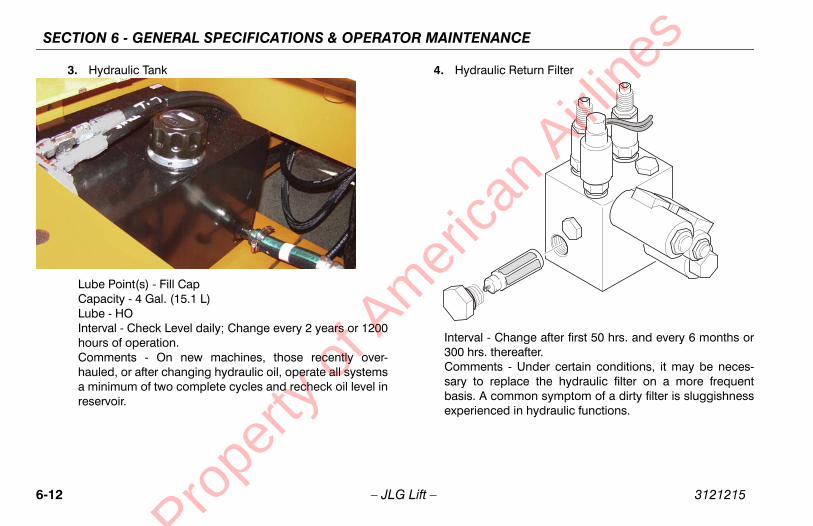
SECTION 6 - GENERAL SPECIFICATIONS & OPERATOR MAINTENANCE
6-1 3121215
ulic Return Filter
- Change after first 50 hrs. and every 6 months or thereafter.nts - Under certain conditions, it may be neces-replace the hydraulic filter on a more frequent common symptom of a dirty filter is sluggishnessced in hydraulic functions.
an A
irline
s
2 – JLG Lift –
3. Hydraulic Tank
Lube Point(s) - Fill CapCapacity - 4 Gal. (15.1 L)Lube - HOInterval - Check Level daily; Change every 2 years or 1200hours of operation.Comments - On new machines, those recently over-hauled, or after changing hydraulic oil, operate all systemsa minimum of two complete cycles and recheck oil level inreservoir.
4. Hydra
Interval 300 hrs.Commesary to basis. Aexperien
Prope
rty o
f Am
eric

FICATIONS & OPERATOR MAINTENANCE
6-13
heel Bearings
e Point(s) - Repackacity - A/Re - MPGrval - Every 2 years or 1200 hours of operation
indles/Bushing
acity - A/Re - Lithium Lubricantrval - Every 2 years or 1200 hours of operationments - At Spindle/Bushing Replacement; Coat I.D. of
hings prior to installing king pins.
an A
irline
s
SECTION 6 - GENERAL SPECI3121215 – JLG Lift –
5. Wheel Drive Hub
Lube Point(s) - Level/Fill PlugCapacity - 17 oz. (1/2 Full)Lube - EPGLInterval - Check level every 3 months or 150 hrs of opera-tion; change every 2 years or 1200 hours of operation
6. W
LubCapLubInte
7. Sp
CapLubInteCombus
Prope
rty o
f Am
eric

SECTION 6 - GENERAL SPECIFICATIONS & OPERATOR MAINTENANCE
6-1 3121215
int(s) - Fill Cap - Refer to Engine ManualO 3 Months or 150 hours of operationnts - Check level daily/Change in accordance with
anual.
an A
irline
s
4 – JLG Lift –
8. Boom Pivot Pins/Bushing
Capacity - A/RLube - Lithium LubricantInterval - Every 2 years or 1200 hours of operationComments - At boom pivot pins/bushing replacement;Coat I.D. of bushings prior to installing pivot pins.
9. Engine
Lube PoCapacityLube - EInterval -Commeengine m
Prope
rty o
f Am
eric

FICATIONS & OPERATOR MAINTENANCE
6-15
move battery cables from each battery post one at a e, negative first. Clean cables with acid neutralizing
lution (e.g. baking soda and water or ammonia) and ire brush. Replace cables and/or cable clamp bolts as quired.
lean battery post with wire brush then re-connect cable post. Coat non-contact surfaces with mineral grease petroleum jelly.
hen all cables and terminal posts have been cleaned, sure all cables are properly positioned and do not get
nched. Close battery compartment cover.
art hydraulic system and ensure that it functions prop-ly.
an A
irline
s
SECTION 6 - GENERAL SPECI3121215 – JLG Lift –
6.4 BATTERY MAINTENANCE AND CHARGING
Battery Maintenance, Quarterly1. Open battery compartment cover to allow access to bat-
tery terminals and vent caps.
WHEN ADDING WATER TO BATTERIES, ADD WATER UNTIL ELECTRO-LYTE COVERS PLATES. DO NOT CHARGE BATTERIES UNLESS ELEC-TROLYTE COVERS THE PLATES.
NOTE: When adding distilled water to batteries, non-metalliccontainers and/or funnels must be used.
To avoid electrolyte overflow, add distilled water to batter-ies after charging.
When adding water to the battery, fill only to level indi-cated or 3/8" above separators.
2. Remove all vent caps and inspect electrolyte level of each cell. Electrolyte level should be to the ring approxi-mately one inch from top of battery. Fill batteries with distilled water only. Replace and secure all vent caps.
3. Retimsowre
4. Ctoor
5. Wenpi
6. Ster
Prope
rty o
f Am
eric

SECTION 6 - GENERAL SPECIFICATIONS & OPERATOR MAINTENANCE
6-1 3121215
Op
EXHLAT
WHEFOREMEWILCHA
NOT
TO ASPAWEA
rging (On Board Charger)imum battery life:
oid completely discharging the batteries.
lly charge the batteries each day the machine ised.
harge the batteries at available times betweenarging.
sure the battery fluid covers the battery platesfore charging, but to avoid overflow, do not top
f the fluid level until charging.
rge the batteries, connect the charger to a 115 urce with a 15 amp minimum capacity.
harger will shut off automatically when the batter- fully charged.
arge cycle is complete when the ammeter reads s. Any reading indicates the charge cycle is not ete.
ed batteries will take approximately 17 hours to .
an A
irline
s
6 – JLG Lift –
tional On Board Generator
AUST GAS HAZARD. RUN THE GENERATOR IN A WELL VENTI-ED AREA ONLY.
N THE GENERATOR ENABLE CONTROL LOCATED IN THE PLAT-M CONTROL BOX IS IN THE ON POSITION AND THE GROUNDRGENCY STOP SWITCH IN ON (PULLED OUT), THE GENERATOR
L START AUTOMATICALLY WHEN THE BATTERIES REACH A LOW-RGE STATE AUTOMATICALLY CHARGING THE BATTERIES.
E: The engine will automatically shut down under the follow-ing conditions:
High Engine Oil TemperatureLow Engine Oil PressureEngine OverspeedGenerator Overvoltage
VOID INJURY FROM AN EXPLOSION, DO NOT SMOKE OR ALLOWRKS OR A FLAME NEAR BATTERY DURING SERVICING. ALWAYSR EYE AND HAND PROTECTION WHEN SERVICING BATTERIES.
Battery Cha1. For max
a. Av
b. Fuus
c. Cch
d. Bebeof
2. To chavolt so
3. The Cies are
4. The ch0 ampcompl
5. Depletcharge
Prope
rty o
f Am
eric
FICATIONS & OPERATOR MAINTENANCE
6-17
any damage to the bead area cords of the tire
damaged but is within the above noted criteria, the tireinspected on a daily basis to insure the damage hasgated beyond the allowable criteria.
lacement
mmends a replacement tire be the same size, ply andoriginally installed on the machine. Please refer to the Manual for the part number of the approved tires for a machine model. If not using a JLG approved replace- we recommend that replacement tires have the follow-cteristics:
Equal or greater ply/load rating and size of original
Tire tread contact width equal or greater than original
Wheel diameter, width, and offset dimensions equal tothe original
Approved for the application by the tire manufacturer(including inflation pressure and maximum tire load)
pecifically approved by JLG Industries Inc. do not foam filled or ballast filled tire assembly with a pneu-. When selecting and installing a replacement tire,at all tires are inflated to the pressure recommended
an A
irline
s
SECTION 6 - GENERAL SPECI3121215 – JLG Lift –
6.5 TIRES & WHEELS
Tire InflationThe air pressure for pneumatic tires must be equal to the airpressure that is stenciled on the side of the JLG product orrim decal for safe and proper operational characteristics.
Tire Damage
For pneumatic tires, JLG Industries, Inc. recommends that whenany cut, rip, or tear is discovered that exposes sidewall or treadarea cords in the tire, measures must be taken to remove theJLG product from service immediately. Arrangements must bemade for replacement of the tire or tire assembly.
For polyurethane foam filled tires, JLG Industries, Inc. recom-mends that when any of the following are discovered, measuresmust be taken to remove the JLG product from service immedi-ately and arrangements must be made for replacement of thetire or tire assembly.
• a smooth, even cut through the cord plies whichexceeds 3 inches (7.5 cm) in total length
• any tears or rips (ragged edges) in the cord plieswhich exceeds 1 inch (2.5 cm) in any direction
• any punctures which exceed 1 inch in diameter
•
If a tire is must be not propa
Tire Rep
JLG recobrand as JLG Partsparticularment tire,ing chara
•
•
•
•
Unless sreplace amatic tireensure th
Prope
rty o
f Am
eric

SECTION 6 - GENERAL SPECIFICATIONS & OPERATOR MAINTENANCE
6-1 3121215
bo
Wh
Tfosupfare
llation important to apply and maintain proper wheelue.
ST BE INSTALLED AND MAINTAINED AT THE PROPERVENT LOOSE WHEELS, BROKEN STUDS, AND POSSI- SEPARATION OF WHEEL FROM THE AXLE. BE SURE
HE NUTS MATCHED TO THE CONE ANGLE OF THE
nuts to the proper torque to prevent wheels from. Use a torque wrench to tighten the fasteners. Ifve a torque wrench, tighten the fasteners with aen immediately have a service garage or dealer
g nuts to the proper torque. Over-tightening willking the studs or permanently deforming the holes in the wheels. The proper procedure for
els is as follows:
ll nuts by hand to prevent cross threading. DO se a lubricant on threads or nuts.
an A
irline
s
8 – JLG Lift –
y JLG. Due to size variations between tire brands, both tiresn the same axle should be the same.
eel Replacement
he rims installed on each product model have been designedr stability requirements which consist of track width, tire pres-re, and load capacity. Size changes such as rim width, center
iece location, larger or smaller diameter, etc., without writtenctory recommendations, may result in an unsafe conditiongarding stability.
Wheel InstaIt is extremelymounting torq
WHEEL NUTS MUTORQUE TO PREBLE DANGEROUSTO USE ONLY TWHEEL.
Tighten the lugcoming looseyou do not halug wrench, thtighten the luresult in breamounting studattaching whe
1. Start aNOT u
Prope
rty o
f Am
eric

FICATIONS & OPERATOR MAINTENANCE
6-19
heel nuts should be torqued after first 50 hours of eration and after each wheel removal. Check torque ery 3 months or 150 hours of operation.
PPLEMENTAL INFORMATIONllowing information is provided in accordance with thements of the European Machinery Directive 2006/42/
d is only applicable to CE machines.
ctric powered machines, the equivalent continuous A-ted sound pressure level at the work platform is less0dB(A)
mbustion engine powered machines, guaranteed Power Level (LWA) per European Directive 2000/14/oise Emission in the Environment by Equipment forutdoors) based on test methods in accordance with III, Part B, Method 1 and 0 of the directive, is 104 dB.
bration total value to which the hand-arm system isted does not exceed 2,5 m/s2. The highest root mean value of weighted acceleration to which the whole
s subjected does not exceed 0,5 m/s2.
an A
irline
s
SECTION 6 - GENERAL SPECI3121215 – JLG Lift –
2. Tighten nuts in the following sequence:
3. The tightening of the nuts should be done in stages. Fol-lowing the recommended sequence, tighten nuts per wheel torque chart.
4. Wopev
6.6 SUThe forequireEC an
For eleWeighthan 7
For coSoundEC (NUse OAnnex
The visubjecsquarebody i
Table 6-12. Wheel Torque Chart
TORQUE SEQUENCE
1st Stage 2nd Stage 3rd Stage
40 ft. lbs.(55 Nm)
100 ft. lbs.(130 Nm)
170 ft. lbs.(255 Nm)
Prope
rty o
f Am
eric

SECTION 6 - GENERAL SPECIFICATIONS & OPERATOR MAINTENANCE
6-2 3121215
an A
irline
s
0 – JLG Lift –
NOTES:
Prope
rty o
f Am
eric

TION 7 - INSPECTION AND REPAIR LOG
7-1
D REPAIR LOG
ir Log
nts
an A
irline
s
SEC3121215 – JLG Lift –
SECTION 7. INSPECTION ANMachine Serial Number _______________________________________
Table 7-1. Inspection and Repa
Date Comme
Prope
rty o
f Am
eric

SECTION 7 - INSPECTION AND REPAIR LOG
7-2 3121215
og
an A
irline
s
– JLG Lift –
Table 7-1. Inspection and Repair L
Date Comments
Prope
rty o
f Am
eric

TR
AN
SF
ER
OF
OW
NE
RS
HIP
To
Pro
du
ct O
wn
er:
If y
ou
no
w o
wn
bu
t A
RE
NO
T t
he
ori
gin
al p
urc
has
er o
f th
e p
rod
uct
co
vere
d b
y th
is
man
ual
, we
wo
uld
like
to
kn
ow
wh
o y
ou
are
. Fo
r th
e p
urp
ose
of
rece
ivin
g s
afet
y-re
late
d
bu
lleti
ns,
it is
ver
y im
po
rtan
t to
kee
p J
LG
Ind
ust
ries
, In
c. u
pd
ated
wit
h t
he
curr
ent
ow
ner
ship
of
all J
LG
pro
du
cts.
JL
G m
ain
tain
s o
wn
er in
form
atio
n f
or
each
JL
G p
rod
uct
an
d u
ses
this
info
rmat
ion
in c
ases
wh
ere
ow
ner
no
tifi
cati
on
is n
eces
sary
.P
leas
e u
se t
his
fo
rm t
o p
rovi
de
JLG
wit
h u
pd
ated
info
rmat
ion
wit
h r
egar
d t
o t
he
curr
ent
ow
ner
ship
of
JLG
pro
du
cts.
Ple
ase
retu
rn c
om
ple
ted
fo
rm t
o t
he
JLG
Pro
du
ct
Saf
ety
& R
elia
bili
ty D
epar
tmen
t vi
a fa
csim
ile o
r m
ail t
o a
dd
ress
as
spec
ifie
d b
elo
w.
Th
ank
Yo
u,
Pro
du
ct S
afet
y &
Rel
iab
ility
Dep
artm
ent
JLG
Ind
ust
ries
, In
c.13
224
Fo
un
tain
hea
d P
laza
Hag
erst
ow
n, M
D21
742
US
AT
elep
ho
ne:
+1-
717-
485-
6591
Fax
: +1
-301
-745
-371
3
NO
TE
: L
ease
d o
r re
nte
d u
nit
s sh
ou
ld n
ot
be
incl
ud
ed o
n t
his
fo
rm.
Mfg
. Mo
del
: __
____
____
___ _
____
____
____
____
____
____
____
____
____
____
____
____
_
Ser
ial N
um
ber
: __
____
____
____
____
____
____
____
____
____
____
____
____
____
____
__
Pre
vio
us
Ow
ner
: __
____
____
____
____
____
____
____
____
____
____
____
____
____
____
_
Ad
dre
ss:
____
____
____
____
____
____
____
____
____
____
____
____
____
____
____
____
_
____
____
____
____
____
____
____
____
____
____
____
____
____
____
____
____
____
____
_
Co
un
try:
__
____
____
____
____
____
___
Tel
eph
on
e: (
____
___ )
___
____
____
____
____
_
Dat
e o
f T
ran
sfer
: __
____
____
____
____
____
____
____
___
Cu
rren
t O
wn
er:
____
____
____
____
____
____
____
____
____
____
____
____
____
____
____
Ad
dre
ss:
____
____
____
___ _
____
____
____
____
____
____
____
____
____
____
____
____
_
____
____
____
____
____
____
____
____
____
____
____
____
____
____
____
____
____
____
_
Co
un
try:
__
____
____
____
____
____
___
Tel
eph
on
e: (
____
___)
___
____
____
____
____
_
Wh
o in
yo
ur
org
aniz
atio
n s
ho
uld
we
no
tify
?
Nam
e:
____
____
____
____
____
____
____
____
____
____
____
____
____
____
____
____
___
Tit
le:_
____
____
____
____
____
____
____
____
____
____
____
____
____
____
____
____
___
��
����
���
�
��
� ��
�
�
��
��
Prope
rty o
f Am
erica
n Airli
nes

Prope
rty o
f Am
erica
n Airli
nes
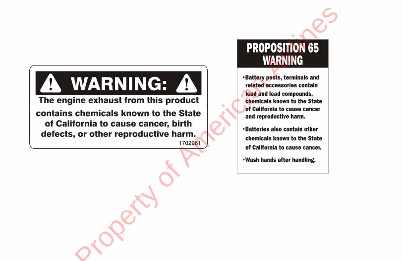
Prope
rty o
f Am
erica
n Airli
nes

Corporate OfficeJLG Industries, Inc.1 JLG DriveMcConnellsburg PA. 17233-9533USA
(717) 485-5161 (717) 485-6417
JLG Worldwide LocationsJLG Industries (Australia)P.O. Box 511911 Bolwarra RoadPort MacquarieN.S.W. 2444Australia
+61 2 65 811111
+61 2 65813058
JLG Latino Americana Ltda.Rua Eng. Carlos Stevenson,80-Suite 7113092-310 Campinas-SPBrazil
+55 19 3295 0407
+55 19 3295 1025
JLG Industries (UK) LtdBentley HouseBentley AvenueMiddletonGreater ManchesterM24 2GP - England
+44 (0)161 654 1000
+44 (0)161 654 1001
JLG France SASZ.I. de Baulieu47400 FauilletFrance
+33 (0)5 53 88 31 70
+33 (0)5 53 88 31 79
JLG Deutschland GmbHMax-Planck-Str. 21D - 27721 Ritterhude - IhlpohlGermany
+49 (0)421 69 350 20
+49 (0)421 69 350 45
JLG Equipment Services Ltd.Rm 1107 Landmark North39 Lung Sum AvenueSheung Shui N. T.Hong Kong
(852) 2639 5783
(852) 2639 5797
JLG Industries (Italia) s.r.l.Via Po. 2220010 Pregnana Milanese - MIItaly
+39 029 359 5210
+39 029 359 5845
Oshkosh-JLG Singapore Technology Equipment Pte Ltd29 Tuas Ave 4,Jurong Industrial EstateSingapore, 639379
+65-6591 9030
+65-6591 9031
Plataformas Elevadoras JLG Iberica, S.L.Trapadella, 2P.I. Castellbisbal Sur08755 Castellbisbal, BarcelonaSpain
+34 93 772 4700
+34 93 771 1762
JLG Sverige ABEnkopingsvagen 150Box 704SE - 176 27 JarfallaSweden
+46 (0)850 659 500
+46 (0)850 659 534
www.jlg.com
3121215
Prope
rty o
f Am
erica
n Airli
nes