property of american airlines · if you have a question if you have any question regarding the...
TRANSCRIPT
Lower Deck Loader
CHAMP70W
Maintenance Manual
Docu-No.: 6110825-826_WA_en(us)
For CHAMP70 Service PersonnelPro
perty
of A
mer
ican
Airline
s

PALLET CONTAINER LOADER CHAMP70
Published by
TREPEL Airport Equipment GmbH
Sales/Marketing
Customer Service
Hagenauer Str. 42
D-65203 Wiesbaden
Telephone: +49 (6 11) 880 88-0
Telefax: +49 (6 11) 880 88-11
E-mail: [email protected]
Internet: http://www.trepel.com
Plant/Purchasing
Administration
Hochhäuser Str. 18
D-97941 Tauberbischofsheim
Telephone: +49 (93 41) 899-0
Telefax: +49 (93 41) 899-339
E-maill: [email protected]
Docu-No.
6110825 - 6110826_WA_en (us)
Date issued
18.05.2015
California Proposition 65 Warning California Proposition 65 Warning
Diesel engine exhaust and some of its consti-tuents are known to state of California to cause cancer, birth defects and other repro-ductive harm.
Battery posts, terminals, and related accesso-ries contain lead and lead compounds, che-micals known to the state of California to cause cancer and reproductive harm. Wash hands after handling.
Prope
rty o
f Am
erica
n Airli
nes
0-0 Page 1
MAY 18/15
PALLET CONTAINER LOADER CHAMP70
Copyright
© 2015 TREPEL Airport Equipment GmbH
This documentation, including all of its parts and chapters is the intellectual property of TREPEL Airport Equipment GmbH and is copyright-protected by national and international laws.
Any use or modification of this documentation or its contents or of parts of the documentation outside of the confines of the copyright law is not permitted without the written approval by TREPEL Airport Equipment GmbH and is liable to prosecution. This is valid in particular for copying, translating, micro-filming, and the storage and processing in electronic systems. All rights reserved. Infringe-ments of these provisions will be prosecuted.
TREPEL Airport Equipment GmbH will not assume liability for damages due to unauthorized use of the contents in the documentation by natural persons or corporate bodies. TREPEL Airport Equip-ment GmbH reserves the right to change this documentation at any time.
Prope
rty o
f Am
erica
n Airli
nes
0-0 Page 2
MAY 18/15

PALLET CONTAINER LOADER CHAMP70
Warranty
(a) With respect to all products provided to American hereunder, Supplier warrants that such pro-ducts will (i) conform in all respects to the applicable specifications and drawings, (ii) be free from all defects, whether patent or latent, in materials, design and workmanship, and (iii) be free and clear of and from all liens, charges and encumbrances of any kind or nature whatsoever caused by or ari-sing by, through or under Supplier. This warranty is valid as to any product or part for the longer of four (4) years or 4500 operating hours, whichever occurs first, after commissioning thereof. The war-ranty will include all rotable parts but not include expendable parts such as filters, tires, etc.
(b) In the event of any breach of the warranty set forth above (a "Defect"), American shall repair the product containing the Defect, all at Supplier's sole cost and expense (including parts). Supplier shall be responsible for the labor expenses incurred by American in the repair of the product at a rate of $35.00 per hour, to be adjusted annually on January 1 of each year commencing from the third year, and for parts used by American for the repair at American's cost. The percentage adjustment to the rate shall correspond to the adjustment to the fully-allocated labor rate published in American's Main-tenance & Engineering Plans Book, the relevant portions of which Supplier will be allowed to review upon request. This reimbursement shall be in the form of a credit or check to American's account and shall be made within thirty (30) days of the notice to Supplier detailing the charges and expen-ses. If the product is not repairable it shall be replaced with a new product.
(c) Supplier shall not be liable under the warranty set forth above for any Defect resulting from a pro-duct having been exposed or subjected, after delivery to American, to:
(i) Any alteration, modification, maintenance, repair, installation, handling, transportation, sto-rage, operation or use that is not in compliance with Supplier's instructions or is otherwise improper, unless caused by Supplier;
(ii) Any accident, contamination, foreign object damage, abuse, neglect or negligence, unless caused by Supplier; or
(iii) Any damage precipitated by any part not supplied by Supplier.
(d) The warranty set forth above shall only apply to products provided by Supplier to American under this Agrement and is in lieu of all other express or implied warranties of Supplier to American with respect to such products, including the implied warranties of merchantability and of fitness for a par-ticular purpose. Without limiting or otherwise adversely affecting Supplier's liability for secondary or resultant damage resulting or arising from adefect or any right or remedy expressly granted or reser-ved to American herein, in no event shall Supplier be liable to American for special or consequential damages sufferedor incurred by American in connection with this Agreement under any contract, tort, strictliability or other theory, excluding gross negligence, recklessness or willful misconduct.
(e) Supplier further warrants that in the 5th year or after the 4500 hours, whichever occurs first, after commissioning of any loader unit (after the warranty has expired), the maximum cost to repair any loader unit will not exceed $2000.00. Should repair of any unit exceed this amount, Supplier will cre-dit American the difference. This includes both parts used and labor expenses as set forth above.
(f) Supplier will invoice American for all warranty replacement parts that are supplied for American installation. American shall be entitled to full or part credit against the cost of such part orther than transportation charges, upon the return of the failed part and determination by the Supplier that such failure is covered by warranty. Such invoice shall be payable in full unless the failed part is returned within thirty (30) days after invoice date.
Prope
rty o
f Am
erica
n Airli
nes
0-0 Page 3
MAY 18/15

PALLET CONTAINER LOADER CHAMP70
IF YOU HAVE A QUESTION
If you have any question regarding the applicable warranty on your Aircraft Ground Support Equip-ment contact:
TREPEL Airport Equipment GmbHHagenauerstraße 4265203 WiesbadenGermany+49 611 880 88-0
Any problems that cannot be resolved by Owner after discussion with the service representative per-forming repairs should be referred to the Managing Director of TREPEL Airport Equipment GmbH, at the above address.
Prope
rty o
f Am
erica
n Airli
nes
0-0 Page 4
MAY 18/15

PUSHBACK TRACTOR CHALLENGER150
This page intentionally left blank.
Prope
rty o
f Am
erica
n Airli
nes
0-0 Page 5
MAY 18/15

Chapter/Section Page
Maintenance and RepairLOWER DECK LOADER CHAMP 70
TABLE OF CONTENTS
CHAPTER 4MAINTENANCE AND REPAIR
Servicing 4-1 1
1. About this Manual 1A. General 1B. Additional Documents 2C. Characters and Symbols Used 3
2. General Safety Instructions 4A. Intended use 4B. Qualifications for Service Personnel 5C. Safety Gear for Service Personnel 5D. Danger area 6E. Safety regulations 7
3. Maintenance and Repair 16A. Maintenance schedule 16B. Tools and specialized tools 28C. Secure raised platform 30D. Lubricating points 34E. Oil level checks 45F. Maintenance on the motor 55G. Maintenance on Wheels/Axles/Steering/Brakes 60H. Maintenance on the platforms / transport system 76I. Maintenance of the hydraulic system 79J. Maintenance of the electrical system 129
4. Operational Materials 149A. Safety Information 149B. Fuels 151C. Oils for Equipment Units 153D. Lubricating Greases 156
Troubleshooting 4-2 1
1. Troubleshooting 1A. Tasks before troubleshooting 1B. Troubleshooting Table 2
Prope
rty o
f Am
erica
n Airli
nes
Page 14-CONTENTS May 18/15

Maintenance and RepairLOWER DECK LOADER CHAMP 70
This page intentionally left blank.
Prope
rty o
f Am
erica
n Airli
nes
Page 2(Blank) May 18/154-CONTENTS
Maintenance and Repair LOWER DECK LOADER CHAMP 70
Section 1Servicing
1. About this Manual
Before servicing or repairing the CHAMP 70, please carefully read the relevant sections in this manual.Always observe the safety instructions (see Subsection 2 "General Safety Instructions", page 4).
A. General
This maintenance manual should help you become familiar with the routine maintenance work on the CHAMP 70.
This maintenance manual contains important information on the safe and proper servicing of the CHAMP 70.
This maintenance manual should help you with any repair you may have to perform on the CHAMP 70.
Observe these instructions in order to:
• Avoid dangers.• Reduce repair costs and downtime.• Increase the reliability and operating life of the CHAMP 70.
This manual only describes maintenance and repair work on the CHAMP 70 that may be performed by the operating company's service personnel.
Maintenance and repair work on CHAMP 70 not described in this manual may only be carried out by TREPEL's customer service staff.
A copy of the maintenance manual must be available to the service personnel at all times.
Prope
rty o
f Am
erica
n Airli
nes
Page 14-1 May 18/15

Maintenance and RepairLOWER DECK LOADER CHAMP 70
B. Additional Documents
In addition to this maintenance manual, you also receive the following documents for the CHAMP 70:
• Instruction Manual• Emergency operating measures• Transport instruction manual• Factory settings/production test documents• Hydraulic diagrams• Connection diagrams• Operating manual/spare parts (motor)• Maintenance/spare parts list (front axle)• Manufacturer's information for purchased parts (non-OEM parts).• Spare parts lists
Service address of our customer service:
Hagenauer Str. 42
D-65203 Wiesbaden
Phone: +49 (6 11) 880 88-0
Fax: +49 (6 11) 880 88-11
e-mail: [email protected]
Internet: http://www.trepel.com
Prope
rty o
f Am
erica
n Airli
nes
Page 24-1 May 18/15

Maintenance and RepairLOWER DECK LOADER CHAMP 70
C. Characters and Symbols Used
Pictographs
All of the pictographs used on the CHAMP 70 are based on internationally accepted IATA proposals.
The meanings of the pictographs are explained in the instruction manual.
Symbols
Symbols for the maintenance
Symbol Meaning
Dangers to persons. Non-observance leads to death or serious injury.
Dangers to persons. Non-observance may lead to death or serious injury.
Dangers to persons. Non-observance may lead to injury.
Risks of property damage.
Necessary measures for avoiding a danger.
(1) (2) ...
Step-by-step guide.Please observe the order of the steps to be taken.
INFORMATION Information for better understanding or for optimizing the workflow.
Symbol Meaning
Lubrication of the lubricating nipples with the grease gun.
Lubrication of sliding surfaces with a brush.
Spraying the chains with chain spray.
Oiling of movable components with the oil can.Prope
rty o
f Am
erica
n Airli
nes
Page 34-1 May 18/15
Maintenance and RepairLOWER DECK LOADER CHAMP 70
2. General Safety Instructions
The following contains a summary of all important safety instructions for repairing and servicing theCHAMP 70.
All personnel who service, repair or work on the CHAMP 70 must read and implement these safetyinstructions.
Furthermore, all other accident prevention regulations in this manual, Occupational Safety und HealthAdministration (OSHA), environmental protection regulations and all other federal, national and regionalregulations and laws that are effective at the place of operation must be observed at all times.
Never operate the CHAMP 70 when under the influence of alcohol, drugs, or medication. Some medica-tions may impair your ability to safely operate the CHAMP 70. Please consult your doctor and inform theshift manager if you are taking medication.
A. Intended use
The CHAMP 70 is intended for loading and unloading cargo from high-capacity aircraft:
• LD containers in lower deck cargo bays• 10-ft units at heights of up to 3.7 m (12 ft).
The CHAMP 70 may be operated at wind speeds of up to 20 m/s (40 knots, 45 mph).
Cargo may be dispatched at a lifting height of up to 3.7 m (12 ft).
The maximum specified container weights may not be exceeded.
Table 1: Container weights
The CHAMP 70 may
• not be driven while loaded with cargo.• not be driven long distances (> 10 km, approx. 6 miles).• not be used for transporting persons.• not be used as a lifting or working platform.• not be used as an elevator for cargo/loading personnel.
Container Max. weight
LD container 1,700 kg (3,752 lb)
10-ft unit 6,800 kg (15,000 lb)
Prope
rty o
f Am
erica
n Airli
nes
Page 44-1 May 18/15

Maintenance and RepairLOWER DECK LOADER CHAMP 70
B. Qualifications for Service Personnel
The CHAMP70 may only be serviced or repaired by personnel qualified and authorized to do so.
Service personnel must
• be at least 18 years of age, as far as no other federal, state or regional laws or any otherapplicable laws dictate a different minimum age.
• Possess the physical and mental capabilities required to drive an automotive vehicle.• Have received instruction in and be able to perform First Aid.• Know the accident prevention regulations and safety instructions of the airport and be able to
apply them.• Know the traffic rules of the airport runways and be able to apply them.• Possess good knowledge regarding the layout of the airport runways.• know the locations of the airport runways and roads as well as the safety areas that the
CHAMP 70 may not drive on.• have received theoretical and practical training on the CHAMP 70.• Be a trained electrician or equivalent.• Understand hydraulic systems, recognize the risks and be able to avert them.• Be a trained industrial mechanic or equivalent.• Understand and be able to use the instruction manual.• Understand and be able to apply the Emergency Operating Measures.
Never operate the CHAMP 70 when under the influence of alcohol, drugs, or medication.
C. Safety Gear for Service Personnel
The CHAMP 70 service employee is obliged to wear the personal safety gear provided by the oper-ating company.
The personal safety gear consists of at least:
• Clearly visible work clothing• Head protection• Hearing protection• Work gloves• Safety boots with steel toes• Safety goggles
Prope
rty o
f Am
erica
n Airli
nes
Page 54-1 May 18/15

Maintenance and RepairLOWER DECK LOADER CHAMP 70
D. Danger area
When servicing or repairing, no other persons should be located within the danger area of the CHAMP 70 apart from service personnel.
No other objects should be located within the danger area of the CHAMP 70 apart from the tools and work implements.
Figure 1: Danger area CHAMP 70
Prope
rty o
f Am
erica
n Airli
nes
Page 64-1 May 18/15

Maintenance and RepairLOWER DECK LOADER CHAMP 70
E. Safety regulations
General
Danger of tipping!
In case of high wind speed and simultaneous raised bridge or elevator there exists the danger of tipping the CHAMP 70.
The CHAMP 70 may be operated at wind speeds of up to 20 m/s (40 knots, 45 mph).
Danger of tipping!
When driving with cargo, the danger exists that the cargo can fall off the platform. Furthermore, there exists the danger of tipping the CHAMP 70 if the cargo on the platform shifts from its intended position.
Do not drive the CHAMP 70 while loaded with cargo.
Danger of explosion and fire!
Fuels are easily inflammable and explosive
Smoking is strictly prohibited in the danger area of the CHAMP 70
No open flames or lights in the danger area of the CHAMP 70.
Falling objects!
Objects loaded on the platforms can fall when raising and lowering the platforms.
No other objects or cargo may be located within the danger area of the CHAMP 70 apart fromthe tools and work implements.
Continued rolling of the CHAMP 70!
If the parking brake is not engaged after shutting off the motor or exiting the driver's stand, the CHAMP 70 can continue rolling unintentionally and roll over persons.
The operator has to engage the parking brake before leaving the driver's stand.
The parking brake has to be engaged whenever the CHAMP 70 is stopped or shut down.
Additionally place blocks under the wheels during maintenance work.Pro
perty
of A
mer
ican
Airline
s
Page 74-1 May 18/15

Maintenance and RepairLOWER DECK LOADER CHAMP 70
Untrained personnel!
Uncontrolled movements of the CHAMP 70 as a result of operator errors can lead to life threaten-ing injuries or even death.
The service personnel has to know all of the operating and display elements and be able to operate them.
Disregarding the regulations!
Disregard of the regulations and instructions can lead to life threatening injuries or even death.
Observe all valid accident prevention regulations and instructions.
Observe all valid airport safety regulations and instructions in regard to the runways.
Observe all airport regulations and work instructions.
Observe all of the local airport safety and work regulations applicable to the work places for maintenance and repair activities.
Missing protective clothing!
If the service personnel doesn't wear the mandatory personal protective clothing, this can lead to life threatening injuries or even death.
The service personnel must wear the required safety gear prescribed by law, work regulations or common sense to be protected from predictable injuries.
Consumption of alcohol, drugs, or medication!
The use of alcohol, drugs or medication can severely impair the ability to operate the CHAMP 70.
The use of alcohol, drugs and medications is strictly prohibited at all times.
Property damage!
Due to its low ground clearance, the CHAMP 70 can be damaged if driven on uneven traffic routes.
The CHAMP 70 may only be driven in permitted airport areas and on permitted traffic routes in accordance with local airport regulations.
Other traffic routes may not be used under any circumstances!Prope
rty o
f Am
erica
n Airli
nes
Page 84-1 May 18/15

Maintenance and Repair LOWER DECK LOADER CHAMP 70
Maintaining the operating safety of the CHAMP 70
Operating safety!
Improper maintenance and repair work can endanger the operating safety and functionality of the CHAMP 70. This can lead to life threatening injuries and even death.
The operator is not to perform any maintenance or repair work.
Maintenance and repair work may only be performed by trained qualified technicians author-ized for this.
All maintenance and repair instructions of the manufacturer or from manufacturers of other components and subassemblies must be strictly adhered to.
Structural changes!
Structural changes can endanger the operating safety and functionality of the CHAMP 70. This can lead to life threatening injuries and even death.
No structural changes may be made to the CHAMP 70.
Only use original spare parts.
Any retrofitting or modification on the CHAMP 70 that was not authorized and not previously permitted in writing by Trepel Airport Equipment GmbH automatically voids all warrantee obli-gations by the manufacturer.
Prior to maintenance work
Danger of tipping!
If the CHAMP 70 is parked on uneven or unsecured surfaces there exists the danger of tipping the CHAMP 70.
Only park the CHAMP 70 on secure and even surfaces.
Inspect the stability of the CHAMP 70 before work or before a shift change.
Safety measures!
Missing safety measures endanger the service personnel during the maintenance work.
Secure the CHAMP 70 from rolling away.
No cargo is located on the platform.
Lower both platforms entirely.
Secure the platform against unintended lowering before working underneath the platform.
Switch off motor.
Switch off main battery switch.
Secure against unintended use.
Attach a "Maintenance Work" warning sign.
Prope
rty o
f Am
erica
n Airli
nes
Page 94-1 May 18/15

Maintenance and RepairLOWER DECK LOADER CHAMP 70
Rolling CHAMP 70!
If the parking brake is not engaged, the CHAMP 70 can roll and run over service personnel.
Ensure that the parking brake is engaged during maintenance work.
Ensure that blocks have additionally been placed under the wheels during maintenance work.
Running over persons!
When the motor is running, the CHAMP 70 can suddenly run over service personnel.
Always engage the parking brake or place blocks under the wheels.
While the engine is running, a person must be present on the driver's stand or at the switch cabinet to monitor the CHAMP 70 and to be able to press the emergency off button in case of an emergency.
Lowering platform!
During work on the CHAMP 70, the platforms can suddenly lower and crush service personnel.
Never work under unsecured platforms.
Lower both platforms completely if you do not have to work beneath them.
Lowering platform!
When working under the raised platform, the service personnel can be crushed by lowering plat-forms.
Never work under unsecured platforms.
Secure the raised platforms with maintenance blocks if you have to work under the platform.
Danger of being crushed by platforms!
When securing the platform the service personnel can be crushed by lowering and raising the plat-form.
Always maintain visual and vocal contact to the operator on the driver's stand.
Only position maintenance blocks in the mounting position of the platform once the operator has let go of the control switch/es for raising/lowering and the CHAMP 70 is stationary.
No service personnel may be present in the danger area of the CHAMP 70 during raising or lowering of the platform.
Prope
rty o
f Am
erica
n Airli
nes
Page 104-1 May 18/15

Maintenance and Repair LOWER DECK LOADER CHAMP 70
Danger of poisoning!
In closed rooms the exhausts of the running motors can poison or suffocate the service personnel.
Always ensure good ventilation of the workshop or connect an exhaust hose to the exhaust pipe of the motor.
Spark formation during welding!
Spark formation during welding work can lead to short circuits and trigger fires.
Always switch off the main battery switch before beginning welding work.
Always wait a minimum of 30 minutes before beginning the welding work after the battery loading process.
Tripping danger!
When working on the platform, the service personnel can trip over platform components.
Watch out for parts of the platform that jut out.
Walk carefully.
Wheels and tires
Accident danger!
Negligence and improperly executed work on wheels and tires impair the operating safety of the CHAMP 70 and can lead to severe accidents.
Regularly check wheels and tires for damage and trend thickness.
Defective wheels and wheels with too little tread profile have to be replaced immediately.
Repair work on wheels and tires may only be executed by qualified technicians.
Working on the hydraulic system
Leaking hydraulic oil!
The hydraulic system is under pressure. Suddenly emerging hydraulic oil can squirt into the eyes and injure other body parts.
Depressurize the hydraulic system before performing maintenance on it.
Wear protective goggles when performing any adjustments or inspections.
Regularly check hydraulic lines and hoses for leakage, proper positioning and porosity, repair and replace hydraulic hoses where necessary.
Prope
rty o
f Am
erica
n Airli
nes
Page 114-1 May 18/15

Maintenance and RepairLOWER DECK LOADER CHAMP 70
Leaking hydraulic oil!
When connecting the measuring equipment for the pressure reading with a running motor, sud-denly emerging hydraulic oil can squirt into the eyes and injure other body parts.
Switch off the motor before connecting the measuring equipment to the test points of the hydraulic.
Wear protective goggles when performing any adjustments or inspections.
Harmful to the environment!
Leaking hydraulic oil pollutes the soil and the ground water.
Close all openings with protective caps or rubber stoppers.
Immediately catch leaking oil and dispose of in accordance with the laws and regulations.
Working on the electrical system
Explosion danger!
Gases escaping from batteries are explosive.
Avoid fire, open light, smoking and sparks near batteries.
Only charge batteries in well-ventilated rooms
Always wait a minimum of 30 minutes after the battery loading process before undertaking any welding work.
Do not place any tools on the battery.
Electric shock!
When working on the electrical system, electric shocks can occur and cause life threatening injuries or even death.
Only let qualified service personnel with extensive electrical knowledge perform maintenance and service work.
Switch off main battery switch and motor before work.
Electric shock!
Damages or defective components in the electrical system can cause electric shocks and lead to life threatening injuries or even death.
Damage to the electrical system must be repaired immediately.
Defective components have to be replaced immediately.
Prope
rty o
f Am
erica
n Airli
nes
Page 124-1 May 18/15

Maintenance and Repair LOWER DECK LOADER CHAMP 70
Fire hazard!
Wrong fuses can lead to short circuits and fires.
Only use fuses with the same ampere rating.
Never override blown fuses.
never exchange blown fuses with fuses with a higher voltage consumption.
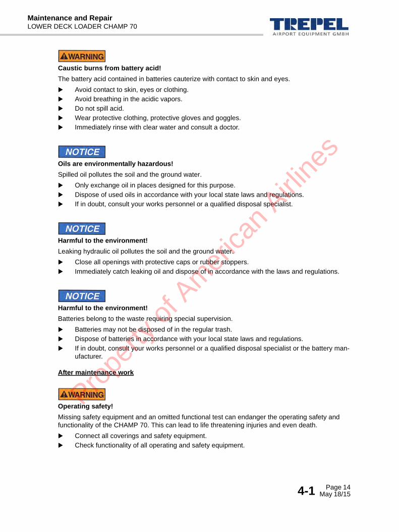
Caustic burns from battery acid!
The battery acid contained in batteries cauterize with contact to skin and eyes.
Avoid contact to skin, eyes or clothing.
Avoid breathing in the acidic vapors.
Do not spill acid.
Wear protective clothing, protective gloves and goggles.
Immediately rinse with clear water and consult a doctor.
Fire hazard!
Wrong sequence when connecting and disconnecting the battery terminals leads to short circuits.
Observe the correct sequence when connecting and disconnecting the battery terminals.
When disconnecting the battery, first remove the negative battery pole, then remove the posi-tive battery pole.
When connecting the battery, first connect the positive battery pole, then connect the nega-tive battery pole.
Operating fuels and lubricants
Oils are toxic!
Oils, especially used oil is toxic and carcinogenic. Hot oil can cause injuries.
Do not inhale or swallow oil and avoid extensive contact.
Protective glasses and clothing must be worn when handling oils.
Observe that the oils are not spilled.
Never let the hot oil come in direct contact with the skin.
Thoroughly rinse skin that had contact with oil.
In case of eye contact, rinse out eyes for 10 to 15 minutes with clear water and consult a doc-tor immediately.
Immediately consult a doctor if the oil has been swallowed.
Always store oils in the original container, never refill or store in drinking containers.
Prope
rty o
f Am
erica
n Airli
nes
Page 134-1 May 18/15
Maintenance and RepairLOWER DECK LOADER CHAMP 70
Caustic burns from battery acid!
The battery acid contained in batteries cauterize with contact to skin and eyes.
Avoid contact to skin, eyes or clothing.
Avoid breathing in the acidic vapors.
Do not spill acid.
Wear protective clothing, protective gloves and goggles.
Immediately rinse with clear water and consult a doctor.
Oils are environmentally hazardous!
Spilled oil pollutes the soil and the ground water.
Only exchange oil in places designed for this purpose.
Dispose of used oils in accordance with your local state laws and regulations.
If in doubt, consult your works personnel or a qualified disposal specialist.
Harmful to the environment!
Leaking hydraulic oil pollutes the soil and the ground water.
Close all openings with protective caps or rubber stoppers.
Immediately catch leaking oil and dispose of in accordance with the laws and regulations.
Harmful to the environment!
Batteries belong to the waste requiring special supervision.
Batteries may not be disposed of in the regular trash.
Dispose of batteries in accordance with your local state laws and regulations.
If in doubt, consult your works personnel or a qualified disposal specialist or the battery man-ufacturer.
After maintenance work
Operating safety!
Missing safety equipment and an omitted functional test can endanger the operating safety and functionality of the CHAMP 70. This can lead to life threatening injuries and even death.
Connect all coverings and safety equipment.
Check functionality of all operating and safety equipment.
Prope
rty o
f Am
erica
n Airli
nes
Page 144-1 May 18/15

Maintenance and Repair LOWER DECK LOADER CHAMP 70
Documentation
Read and understand documentation!
Service personnel has to be familiar with the contents of this maintenance instruction manual and has to apply its instructions.
A copy of the maintenance and repair manual must be available to every member of the service staff when working on the CHAMP 70.
In addition to the maintenance manual, pay attention to the electrical and hydraulic diagrams, the factory settings, the spare parts lists, and manufacturer's information on purchase parts.
Prope
rty o
f Am
erica
n Airli
nes
Page 154-1 May 18/15

Maintenance and RepairLOWER DECK LOADER CHAMP 70
3. Maintenance and Repair
The following provides support for the maintenance and repair of the CHAMP 70.
Trepel recommends to perform maintenance of the CHAMP 70 in accordance with the maintenance schedule. This maintains the operating safety of the CHAMP 70.
Some maintenance and repair work requires special tools (see Subsection B "Tools and specialized tools", page 28).
A. Maintenance schedule
General remarks
Maintenance plans with the following intervals are applied for every component:
• daily • 250 operating hours• 500 operating hours• yearly
The following applies:
• 250 operating hours require quarterly maintenance• 500 operating hours require biannual maintenance.
INFORMATION
The maintenance plans do not contain the maintenance intervals of the vendor parts, e.g. motor or front axle.
Strictly observe the maintenance intervals and instructions in the documentation of the manufacturer of the vendor parts.
Prope
rty o
f Am
erica
n Airli
nes
Page 164-1 May 18/15
Maintenance and Repair LOWER DECK LOADER CHAMP 70
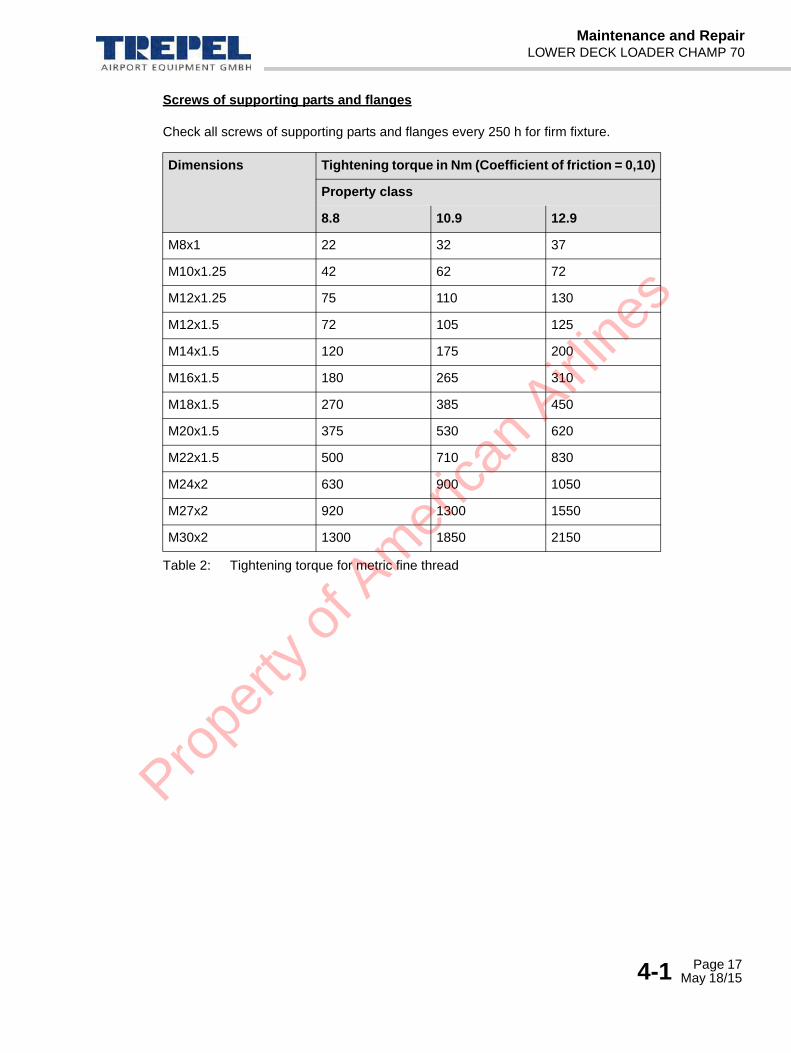
Screws of supporting parts and flanges
Check all screws of supporting parts and flanges every 250 h for firm fixture.
Table 2: Tightening torque for metric fine thread
Dimensions Tightening torque in Nm (Coefficient of friction = 0,10)
Property class
8.8 10.9 12.9
M8x1 22 32 37
M10x1.25 42 62 72
M12x1.25 75 110 130
M12x1.5 72 105 125
M14x1.5 120 175 200
M16x1.5 180 265 310
M18x1.5 270 385 450
M20x1.5 375 530 620
M22x1.5 500 710 830
M24x2 630 900 1050
M27x2 920 1300 1550
M30x2 1300 1850 2150
Prope
rty o
f Am
erica
n Airli
nes
Page 174-1 May 18/15

Maintenance and RepairLOWER DECK LOADER CHAMP 70
Table 3: Tightening torque for standard metric thread
Dimensions Tightening torque in Nm (Coefficient of friction = 0,10)
Property class
8.8 10.9 12.9
M4x0.7 2.4 3.6 4.2
M5x0.8 4.8 7.1 8.3
M6x1 8.3 12 14
M8x1.25 20 30 35
M10x1.5 40 59 69
M12x1.75 69 100 120
M14x2 110 160 190
M16x2 170 250 290
M18x2.5 245 345 405
M20x2.5 340 490 570
M22x2.5 460 660 770
M24x3 590 840 980
M27x3 870 1250 1450
M30x3.5 1450 1900 1950
Prope
rty o
f Am
erica
n Airli
nes
Page 184-1 May 18/15
Maintenance and Repair LOWER DECK LOADER CHAMP 70
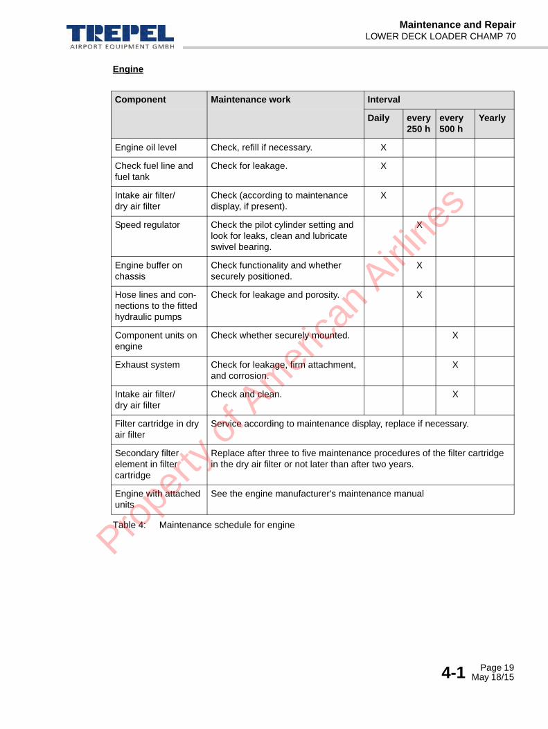
Engine
Table 4: Maintenance schedule for engine
Component Maintenance work Interval
Daily every 250 h
every 500 h
Yearly
Engine oil level Check, refill if necessary. X
Check fuel line and fuel tank
Check for leakage. X
Intake air filter/ dry air filter
Check (according to maintenance display, if present).
X
Speed regulator Check the pilot cylinder setting and look for leaks, clean and lubricate swivel bearing.
X
Engine buffer on chassis
Check functionality and whether securely positioned.
X
Hose lines and con-nections to the fitted hydraulic pumps
Check for leakage and porosity. X
Component units on engine
Check whether securely mounted. X
Exhaust system Check for leakage, firm attachment, and corrosion.
X
Intake air filter/ dry air filter
Check and clean. X
Filter cartridge in dry air filter
Service according to maintenance display, replace if necessary.
Secondary filter element in filter cartridge
Replace after three to five maintenance procedures of the filter cartridge in the dry air filter or not later than after two years.
Engine with attached units
See the engine manufacturer's maintenance manual
Prope
rty o
f Am
erica
n Airli
nes
Page 194-1 May 18/15

Maintenance and RepairLOWER DECK LOADER CHAMP 70
Wheels/axles/steering/brakes
Component Maintenance work Interval
Daily every 250 h
every 500 h
Yearly
Wheels and tires Check for damage. X
Check firm fixture of the rear axle, check profile depth of the tires.
X
Wheel nuts Check tightening torque and tighten; specified tightening torque is 500 Nm (11,870 pdl ft).
X
Wheel nuts after wheel change
Check tightening torque and tighten; recheck torque value after ten hours of operation.
Recheck tightening torque after first ten hours of operation.
Brake/steering sys-tem
Check for leakage; check and adjust the pressure if necessary.
X
Steering cylinder Check for leakage and check cylin-der piston rods for damage.
X
Brake system push buttons
Check for functionality. X
Pressure accumula-tor in the brake sys-tem
Check initial tension, refill if neces-sary. Observe the manufacturer's safety instructions.
X
Fastening nut for hydraulic drive engine on axle drive
Check tightening torque and tighten (specified tightening torque).
X
Prope
rty o
f Am
erica
n Airli
nes
Page 204-1 May 18/15

Maintenance and Repair LOWER DECK LOADER CHAMP 70
Table 5: Maintenance schedule for wheels, axles, steering and brakes
Front axle Lubrication (lubricating points see Subsection D "Lubricating points", page 34).
X
Check oil level of differential gear. X
Check oil level of planetary gear. X
Chassis axle shafts Check that screw connections are firm and secure.
X
Steering unit in driver's stand
Check whether pressure settings are correct.
X
Front axle Oil change axle gears X
Oil change planetary gear X
Front wheel brake See the maintenance manual from the axle manufacturer
Component Maintenance work Interval
Daily every 250 h
every 500 h
Yearly
Prope
rty o
f Am
erica
n Airli
nes
Page 214-1 May 18/15
Maintenance and RepairLOWER DECK LOADER CHAMP 70
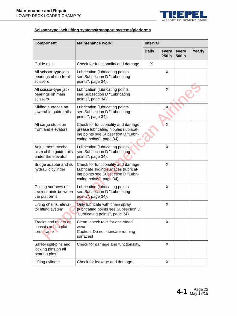
Scissor-type jack lifting systems/transport systems/platforms
Component Maintenance work Interval
Daily every 250 h
every 500 h
Yearly
Guide rails Check for functionality and damage. X
All scissor-type jack bearings of the front scissors
Lubrication (lubricating points see Subsection D "Lubricating points", page 34).
X
All scissor-type jack bearings on main scissors
Lubrication (lubricating points see Subsection D "Lubricating points", page 34).
X
Sliding surfaces on lowerable guide rails
Lubrication (lubricating points see Subsection D "Lubricating points", page 34).
X
All cargo stops on front and elevators
Check for functionality and damage; grease lubricating nipples (lubricat-ing points see Subsection D "Lubri-cating points", page 34).
X
Adjustment mecha-nism of the guide rails under the elevator
Lubrication (lubricating points see Subsection D "Lubricating points", page 34).
X
Bridge adapter and its hydraulic cylinder
Check for functionality and damage. Lubricate sliding surfaces (lubricat-ing points see Subsection D "Lubri-cating points", page 34).
X
Gliding surfaces of the restraints between the platforms
Lubrication (lubricating points see Subsection D "Lubricating points", page 34).
X
Lifting chains, eleva-tor lifting system
Only lubricate with chain spray (lubricating points see Subsection D "Lubricating points", page 34).
X
Tracks and rollers on chassis and in plat-form frame
Clean, check rolls for one-sided wear.Caution: Do not lubricate running surfaces!
X
Safety split-pins and locking pins on all bearing pins
Check for damage and functionality. X
Lifting cylinder Check for leakage and damage. X
Prope
rty o
f Am
erica
n Airli
nes
Page 224-1 May 18/15
Maintenance and Repair LOWER DECK LOADER CHAMP 70
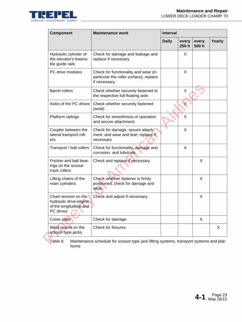
Table 6: Maintenance schedule for scissor-type jack lifting systems, transport systems and plat-forms
Hydraulic cylinder of the elevator's lowera-ble guide rails
Check for damage and leakage and replace if necessary.
X
PC drive modules Check for functionality and wear (in particular the roller surface); replace if necessary.
X
Barrel rollers Check whether securely fastened to the respective full-floating axle.
X
Axles of the PC drives Check whether securely fastened (axial).
X
Platform railings Check for smoothness of operation and secure attachment.
X
Coupler between the lateral transport roll-ers
Check for damage, secure attach-ment, and wear and tear; replace if necessary.
X
Transport / ball rollers Check for functionality, damage and corrosion, and lubricate.
X
Friction and ball bear-ings on the scissor track rollers
Check and replace if necessary. X
Lifting chains of the main cylinders
Check whether fastener is firmly positioned, check for damage and wear.
X
Chain tension on the hydraulic drive engine of the longitudinal and PC drives
Check and adjust if necessary. X
Cover plate Check for damage. X
Weld seams on the scissor-type jacks
Check for fissures. X
Component Maintenance work Interval
Daily every 250 h
every 500 h
Yearly
Prope
rty o
f Am
erica
n Airli
nes
Page 234-1 May 18/15

Maintenance and RepairLOWER DECK LOADER CHAMP 70
Driver's stand
Table 7: Maintenance schedule for driver's stand
Component Maintenance work Interval
Daily every 250 h
every 500 h
Yearly
Driver's lumbar sup-ports
Check whether securely fastened. X
Steering, horn, park-ing brake lever
Check for functionality, secure posi-tioning and proper setting.
X
Pedal bearings Lubrication (lubricating points see Subsection D "Lubricating points", page 34).
X
Steering and control elements on the instrument and oper-ating panel
Check for functionality, leakage and proper electrical contact.
X
Instrument and oper-ating panel
Check whether securely fastened. X
Slide-out mechanism of operating stand
Check for functionality and secure handling.
X
Thrust cylinder of the operating stand
Check for leakage and secure attachment.
X
Sliding surfaces on slide-out mechanism for operating stand
Check for wear, lubricate (lubrication points see Subsection D "Lubricat-ing points", page 34).
X
Prope
rty o
f Am
erica
n Airli
nes
Page 244-1 May 18/15
Maintenance and Repair LOWER DECK LOADER CHAMP 70
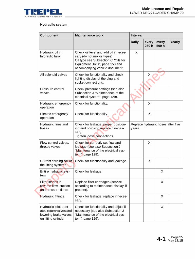
Hydraulic system
Component Maintenance work Interval
Daily every 250 h
every 500 h
Yearly
Hydraulic oil in hydraulic tank
Check oil level and add oil if neces-sary (do not mix oil types). Oil type see Subsection C "Oils for Equipment Units", page 153 and accompanying vehicle document.
X
All solenoid valves Check for functionality and check lighting display of the plug and socket connections.
X
Pressure control valves
Check pressure settings (see also Subsection J "Maintenance of the electrical system", page 129).
X
Hydraulic emergency operation
Check for functionality. X
Electric emergency operation
Check for functionality. X
Hydraulic lines and hoses
Check for leakage, proper position-ing and porosity; replace if neces-sary. Tighten loose connections.
Replace hydraulic hoses after five years.
Flow control valves, throttle valves
Check for correctly set flow and leakage (see also Subsection J "Maintenance of the electrical sys-tem", page 129).
X
Current dividing coil of the lifting systems
Check for functionality and leakage. X
Entire hydraulic sys-tem
Check for leakage. X
Filter inserts in reverse flow, suction and pressure filters
Replace filter cartridges (service according to maintenance display, if present).
X
Hydraulic fittings Check for leakage, replace if neces-sary.
X
Hydraulic pilot oper-ated return valves and lowering brake valves on lifting cylinder
Check for functionality and adjust if necessary (see also Subsection J "Maintenance of the electrical sys-tem", page 129).
X
Prope
rty o
f Am
erica
n Airli
nes
Page 254-1 May 18/15

Maintenance and RepairLOWER DECK LOADER CHAMP 70
Table 8: Maintenance schedule for hydraulic system
All hydraulic cylinders Check for leakage and whether screw connections are firmly tight-ened, replace if necessary.
X
Hydraulic oil Take oil sample and check for impu-rities.
X
Hydraulic oil Change oil. Oil type see Subsection C "Oils for Equipment Units", page 153.
X
All pumps and hydraulic motors for drive mode
Check and service. See manufacturer's maintenance manual
Component Maintenance work Interval
Daily every 250 h
every 500 h
Yearly
Prope
rty o
f Am
erica
n Airli
nes
Page 264-1 May 18/15

Maintenance and Repair LOWER DECK LOADER CHAMP 70
Electrical systems
Table 9: Maintenance schedule for electrical systems
Component Maintenance work Interval
Daily every 250 h
every 500 h
Yearly
Vehicle lighting Check for functionality and damage, replace defective components.
X
All emergency off but-tons
Check for functionality, damage, and correct attachment; check whether their cable connections are firmly attached.
X
All pilot lamps and warning lights
Check for functionality, replace if nec-essary.
X
Batteries Check battery status. X
Battery acid Check acid concentration and clean-ness (see Subsection "Checking bat-tery status", page 132).
X
Electrical fuses Check for corrosion. X
Electrical limit/proxim-ity switches
Check for functionality, damage, secure attachment, and correct switch-ing distance, and adjust or replace if necessary (see Subsection "Proximity switch", page 145 or Subsection "Set switch distance", page 147).
X
Electrical relays and time lag relays
Check for functionality and corrosion; check whether their cable connections are firmly attached.
X
Electrical time lag relays
Check whether delay is as specified (see Subsection "Setting time lag relay", page 142).
X
Cable connections in the switch cabinets
Check for firm attachment and check connections for corrosion.
X
Cable connections in the terminal boxes
Check for firm attachment and check connections for corrosion.
X
Switch cabinet Check for leakage. X
Electrical compo-nents of the engine (generator, starter, controller)
Check and service. See manufacturer's maintenance manual
Prope
rty o
f Am
erica
n Airli
nes
Page 274-1 May 18/15

Maintenance and RepairLOWER DECK LOADER CHAMP 70
B. Tools and specialized tools
The following provides an overview of the required tools.
Before performing any maintenance work, ensure that the tools can be used safely. Only spe-cially trained service personnel instructed by TREPEL may work with the tools.
Toolse
Most of the maintenance work can be executed with the standard tools for mechanics. Always use tools that are in faultless condition. The workshop should be fitted with at least an assembly pit and a device for the exhaust extraction.
Specialized tools
Special tools are needed for performing specific adjustments.
Working on the mechanical systems
Working on the hydraulic system
Designation Measuring range Type
Torque spanner 30-500 Nm (712-11,870 pdl ft) Commercially availa-ble
Feeler gauge 0-1 mm Commercially availa-ble
Micrometer gauge 0-25 mm Commercially availa-ble
Caliper gauge 0-150 mm Commercially availa-ble
Tools for engine Refer to engine manufacturer documentation
Commercially availa-ble
Designation Connection thread Type
Adapter for manometer R1/4 and M16 MAV 1/4 – MA3
Adapter for manometer R1/2 and M16 MAV1/2 – MA3
Measuring hose for manometer con-nection and adapter
M16 and M16 Hydraulic measuring hose
Oil change adapter hose DIN ISO 228, G1 Accessories if engine is equipped with adapter for oil changes.
Prope
rty o
f Am
erica
n Airli
nes
Page 284-1 May 18/15
Maintenance and Repair LOWER DECK LOADER CHAMP 70
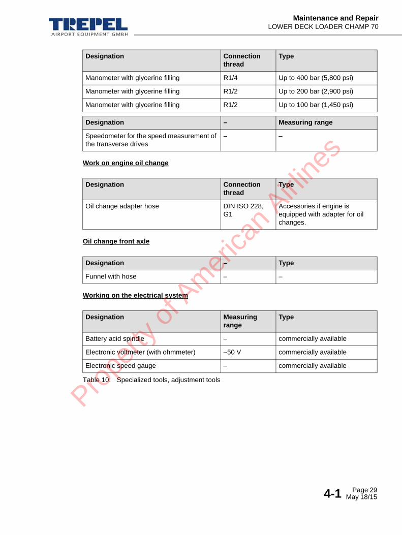
Work on engine oil change
Oil change front axle
Working on the electrical system
Table 10: Specialized tools, adjustment tools
Designation Connection thread
Type
Manometer with glycerine filling R1/4 Up to 400 bar (5,800 psi)
Manometer with glycerine filling R1/2 Up to 200 bar (2,900 psi)
Manometer with glycerine filling R1/2 Up to 100 bar (1,450 psi)
Designation – Measuring range
Speedometer for the speed measurement of the transverse drives
– –
Designation Connection thread
Type
Oil change adapter hose DIN ISO 228, G1
Accessories if engine is equipped with adapter for oil changes.
Designation – Type
Funnel with hose – –
Designation Measuring range
Type
Battery acid spindle – commercially available
Electronic voltmeter (with ohmmeter) –50 V commercially available
Electronic speed gauge – commercially available
Prope
rty o
f Am
erica
n Airli
nes
Page 294-1 May 18/15

Maintenance and RepairLOWER DECK LOADER CHAMP 70
C. Secure raised platform
Some maintenance work must be carried out under the raised platforms. The following describes all measures that must be taken to secure the raised platforms against accidental lowering.
For work carried out underneath the platform, the following applies:
Lowering platform!
When working under the platform the service personnel can be crushed by lowering platforms.
The lowering platform can cause serious injuries or even death to the service personnel.
Never work under unsecured platforms.
Secure the raised platforms with maintenance blocks.
Engage parking brake
Rolling CHAMP 70!
If the parking brake is not engaged, the CHAMP 70 can roll and run over service personnel.
A collision with the rolling CHAMP 70 can cause life threatening injuries and even death.
Ensure that the parking brake is engaged during maintenance work.
Ensure that blocks have additionally been placed under the wheels during maintenance work.
(1) Park the CHAMP 70 in the workshop.
(2) Keep brake pedal pressed down.
(3) Turn driving direction control switch to the right.
The control switch clicks into position.
Control light parking brake on.
Parking brake is engaged.
(4) Release the brake pedal.
Prope
rty o
f Am
erica
n Airli
nes
Page 304-1 May 18/15

Maintenance and Repair LOWER DECK LOADER CHAMP 70
Secure bridge
Figure 2: Maintenance blocks on the bridge
1 Maintenance block
2 Mounting position
3 Maintenance block placed
4 Storage area
Danger of being crushed by platforms!
When securing the bridge the service personnel can be crushed by lowering and raising the bridge.
The lowering platform can cause serious injuries or even death to the service personnel.
Always maintain visual and vocal contact to the operator on the driver's stand.
Only position maintenance blocks in the mounting position of the bridge once the operator has let go of the control switch for bridge up/down and the CHAMP 70 is stationary.
No service personnel may be present in the danger area of the CHAMP 70 during raising or lowering of the bridge.
1 2
3 4
Prope
rty o
f Am
erica
n Airli
nes
Page 314-1 May 18/15
Maintenance and RepairLOWER DECK LOADER CHAMP 70
(1) Press both bridge up/down control switches away from operator.
Bridge moves up.
(2) Remove both maintenance blocks from the storage area.
(3) Place the maintenance blocks in the right and left position of the bridge.
(4) Press both bridge up/down control switches towards the operator.
The bridge lowers.
(5) Press both bridge up/down control switches until the maintenance blocks are pressed against the front scissor-type jack.
The maintenance blocks are secured.
The bridge is secured against unintended lowering.
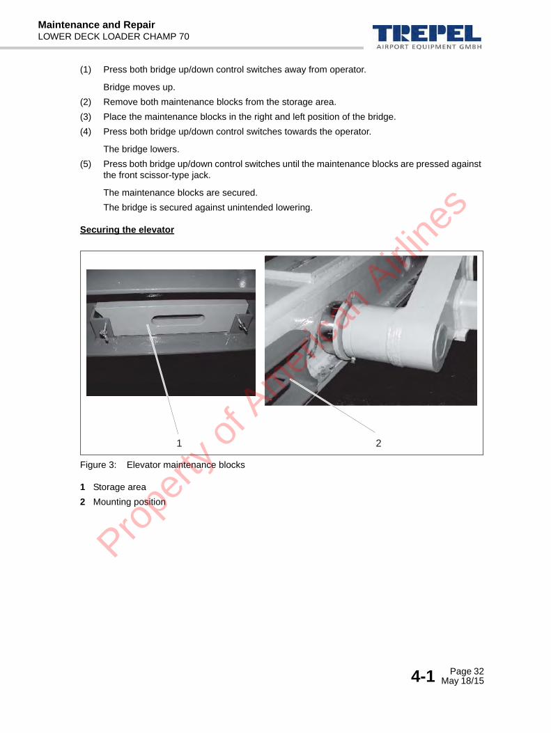
Securing the elevator
Figure 3: Elevator maintenance blocks
1 Storage area
2 Mounting position
1 2
Prope
rty o
f Am
erica
n Airli
nes
Page 324-1 May 18/15
Maintenance and Repair LOWER DECK LOADER CHAMP 70
Danger of being crushed by platforms!
When securing the elevator, the service personnel can be crushed by lowering and raising the ele-vator.
The lowering elevator can cause serious injuries or even death to the service personnel.
Always maintain visual and vocal contact to the operator on the driver's stand.
Only position maintenance blocks in the mounting position of the elevator once the operator has let go of the control switch for elevator up/down and the CHAMP 70 is stationary.
No service personnel may be present in the danger area of the CHAMP 70 during raising or lowering of the elevator.
(1) Press elevator up/down control switch away from operator.
The elevator lifts.
(2) Remove both maintenance blocks from the storage area.
(3) Place the maintenance blocks in the right and left position of the elevator.
(4) Press elevator up/down control switch towards operator.
The elevator lowers.
(5) Press elevator up/down control switch until the maintenance blocks are pressed against the lower track roller bearings of the main scissor-type jack.
The maintenance blocks are secured.
The elevator is secured against unintended lowering.
Turning off the motor
(1) Turn starter switch to position "0".
Motor switches off.
Prope
rty o
f Am
erica
n Airli
nes
Page 334-1 May 18/15

Maintenance and RepairLOWER DECK LOADER CHAMP 70
D. Lubricating points
The following describes all important information for lubricating the CHAMP 70.
Lubricate all lubricating points in an interval of 250 operating hours. Here a grease gun is used for the lubricating nipples and a brush for the gliding surfaces.
The lubricating points are protected by a red cap.
As a lubricating grease an all-purpose grease in accordance with DIN 51502/ (identification: KZK, lithium based, drop point above 170°C / 338°F ) is recommended.
The CHAMP 70 has lubricating points above and below the platform.
Lubricating points above the platform
If the lubricating points are above the platform, observe the following safety instruction:
Tripping danger!
When working on the platform, the service personnel can trip over platform components.
The service personnel can easily be injured when tripping.
Watch out for parts of the platform that jut out.
Walk carefully.
Lubricating points below the platform
If the lubricating points are below the platform, observe the following safety instruction:
Lowering platform!
When working under the platform the service personnel can be crushed by lowering platforms.
The lowering platform can cause serious injuries or even death to the service personnel.
Never work under unsecured platforms.
Secure the raised platforms with maintenance blocks.
Prope
rty o
f Am
erica
n Airli
nes
Page 344-1 May 18/15
Maintenance and Repair LOWER DECK LOADER CHAMP 70
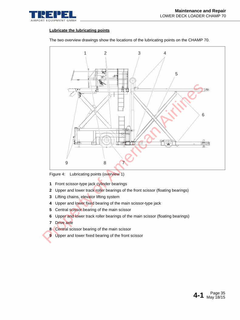
Lubricate the lubricating points
The two overview drawings show the locations of the lubricating points on the CHAMP 70.
Figure 4: Lubricating points (overview 1)
1 Front scissor-type jack cylinder bearings
2 Upper and lower track roller bearings of the front scissor (floating bearings)
3 Lifting chains, elevator lifting system
4 Upper and lower fixed bearing of the main scissor-type jack
5 Central scissor bearing of the main scissor
6 Upper and lower track roller bearings of the main scissor (floating bearings)
7 Drive axle
8 Central scissor bearing of the main scissor
9 Upper and lower fixed bearing of the front scissor
1
5
2 3 4
6
789
Prope
rty o
f Am
erica
n Airli
nes
Page 354-1 May 18/15

Maintenance and RepairLOWER DECK LOADER CHAMP 70
Figure 5: Lubricating points – other (overview 2)
1 Adapter on the bridge
2 Slide-out tray for driver's stand
3 Pedal bearings
4 Gliding surface of the restraints between the platforms
5 Cargo stops
6 Guide rail adjustment mechanism/sliding surfaces of the guide rails
7 Speed regulator
Lubricating with grease gun
(1) Remove the caps indicated in red from the lubricating nipple.
(2) Position the nozzle of grease gun on the lubricating nipple.
(3) Squeeze trigger 4 - 5 times.
The lubricating point is now greased.
(4) Remove nozzle.
(5) Replace cap on lubricating nipple.
The lubricating nipple is now protected from dirt entering it and the lubrication process is com-pleted.
1
52 3 4 6
7
Prope
rty o
f Am
erica
n Airli
nes
Page 364-1 May 18/15

Maintenance and Repair LOWER DECK LOADER CHAMP 70
Lubrication with brush
(1) Lubricate the gliding surfaces and the restraints between the platforms with the brush.
INFORMATION
Do not lubricate the chain drives with grease. Lubricated chain drives can easily soil.
Lubrication with chain spray
(1) Clean soiled chain drives with degreaser.
(2) Lubricate chain drives with chain spray.
Lubrication regulations front axle
The lubrication regulations for the front axle are not described in this maintenance manual.
(1) Observe the lubrication instructions of the manufacturer for front axles in the appendix of the documentation.
Lubricating points
Figure 6: Sliding surfaces and adjustment mechanism of guide rails (rear guide rail depicted)
Prope
rty o
f Am
erica
n Airli
nes
Page 374-1 May 18/15

Maintenance and RepairLOWER DECK LOADER CHAMP 70
Figure 7: Cargo stops
Figure 8: Guideway between platformsPrope
rty o
f Am
erica
n Airli
nes
Page 384-1 May 18/15

Maintenance and Repair LOWER DECK LOADER CHAMP 70
Figure 9: Slide-out tray for driver's stand
Figure 10: Bridge adapter
Prope
rty o
f Am
erica
n Airli
nes
Page 394-1 May 18/15

Maintenance and RepairLOWER DECK LOADER CHAMP 70
Figure 11: Movable parts of the speed regulator
Figure 12: Fixed bearing of the front scissor-type jack, inside
Prope
rty o
f Am
erica
n Airli
nes
Page 404-1 May 18/15

Maintenance and Repair LOWER DECK LOADER CHAMP 70
Figure 13: Fixed bearing, front scissor-type jack
Figure 14: Central scissor bearing of the main scissor
Prope
rty o
f Am
erica
n Airli
nes
Page 414-1 May 18/15

Maintenance and RepairLOWER DECK LOADER CHAMP 70
Figure 15: Guide rail adjustment mechanism
Figure 16: Floating bearing of the main scissor-type jack, top
Prope
rty o
f Am
erica
n Airli
nes
Page 424-1 May 18/15

Maintenance and Repair LOWER DECK LOADER CHAMP 70
Figure 17: Floating bearing of the main scissor-type jack, bottom
Figure 18: Fixed bearing of the main scissor-type jack, top
Prope
rty o
f Am
erica
n Airli
nes
Page 434-1 May 18/15

Maintenance and RepairLOWER DECK LOADER CHAMP 70
Figure 19: Fixed bearing of the main scissor-type jack, bottom
Prope
rty o
f Am
erica
n Airli
nes
Page 444-1 May 18/15

Maintenance and Repair LOWER DECK LOADER CHAMP 70
E. Oil level checks
The following describes the procedures for checking engine and hydraulic oil levels. You can also find information on the inspection of the oil levels for the differential and planetary gears of the front axle.
Walk once around the CHAMP 70 daily and inspect for possible oil leakages.
Check the oil levels for the engine and the hydraulic system daily.
Check the transmission oil level in the planetary and differential gears of the front axle every 250 operating hours.
Oil specifications see Subsection 4 "Operational Materials", page 149.
Oils are toxic!
Oils, especially used oil is toxic and carcinogenic. Hot oil can cause injuries.
The improper handling of oils can seriously injure service personnel.
Do not inhale or swallow oil and avoid extensive contact.
Protective glasses and clothing must be worn when handling oils.
Observe that the oils are not spilled.
Never let the hot oil come in direct contact with the skin.
Thoroughly rinse skin that had contact with oil.
In case of eye contact, rinse out eyes for 10 to 15 minutes with clear water and consult a doc-tor immediately.
Immediately consult a doctor if the oil has been swallowed.
Always store oils in the original container, never refill or store in drinking containers.
Oils are environmentally hazardous!
Spilled oil pollutes the soil and the ground water.
Only exchange oil in places designed for this purpose.
Dispose of used oils in accordance with your local state laws and regulations.
If in doubt, consult your works personnel or a qualified disposal specialist.
Engine oil level
Engine damage!
Too high or too low oil level can damage the engine.
Make sure that the oil level never lies above the "HIGH" mark or below the "LOW" mark.
Only use motor oils approved by the engine manufacturer.
Prope
rty o
f Am
erica
n Airli
nes
Page 454-1 May 18/15
Maintenance and RepairLOWER DECK LOADER CHAMP 70
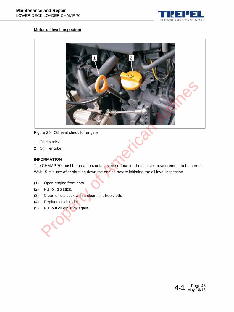
Motor oil level inspection
Figure 20: Oil level check for engine
1 Oil dip stick
2 Oil filler tube
INFORMATION
The CHAMP 70 must be on a horizontal, even surface for the oil level measurement to be correct.
Wait 15 minutes after shutting down the engine before initiating the oil level inspection.
(1) Open engine front door.
(2) Pull oil dip stick.
(3) Clean oil dip stick with a clean, lint-free cloth.
(4) Replace oil dip stick.
(5) Pull out oil dip stick again.
1 2
Prope
rty o
f Am
erica
n Airli
nes
Page 464-1 May 18/15

Maintenance and Repair LOWER DECK LOADER CHAMP 70
Figure 21: Oil dip stick with markings
INFORMATION
The oil level must be between "LOW" mark and the "HIGH" mark.
(6) If the oil level is too low, refill the motor oil using the oil filler tubes.
Engine manufacturer documentation
In the documentation of the engine manufacturer you can find the intervals and procedures for oil change, filling levels and the specifications of the engine oils.
You will find details on the engine oils that are factory-filled in the factory settings record.
HIGH
LOW
Prope
rty o
f Am
erica
n Airli
nes
Page 474-1 May 18/15

Maintenance and RepairLOWER DECK LOADER CHAMP 70
Oil levels front axle
In the front axle, the gear oil levels of both planetary gears and the differential gear should be inspected every 250 operating hours.
MS-E 3060
Figure 22: Front axle: Planetary and differential gears MS-E 3060
1 Filling screw and inspection plug, planetary gear
2 Planetary gear
3 Differential gear, drain screw
4 Differential gear, inspection plug
Oil level inspection planetary gears
(1) Check the oil level of the CHAMP 70 on a level surface.
(2) Always maintain visual and vocal contact to the operator on the driver's stand.
(3) Drive the CHAMP 70 until the checkmark is horizontal to the driving surface (9 o'clock).
(4) Engage parking brake.
(5) Turn off engine.
You may now check the planetary gear's oil level.
1 2
34
Prope
rty o
f Am
erica
n Airli
nes
Page 484-1 May 18/15

Maintenance and Repair LOWER DECK LOADER CHAMP 70
Figure 23: Front axle: Planetary gear MS-E 3060
1 Checkmark
2 Inspection plug, planetary gear
(6) Carefully clean the inspection plug before screwing it off.
(7) Screw off inspection plug.
(8) Check oil level.
The correct level for oil is at the bottom mark of the inspection plug.(9) If the oil level is too low, refill the motor oil.
(10) Check the seals on the inspection plug and replace if necessary.
(11) Screw on inspection plug.
INFORMATION
Use a funnel or hose for refilling the oil into the planetary and differential gear.
Front axle manufacturer documentation
In the documentation of the front axle manufacturer you can find the intervals and procedures for oil change, filling levels and the specifications of the gear oils.
INFORMATION
The vehicle specification sheet has information on which gear oil was filled in at the factory.
2
1
Prope
rty o
f Am
erica
n Airli
nes
Page 494-1 May 18/15
Maintenance and RepairLOWER DECK LOADER CHAMP 70
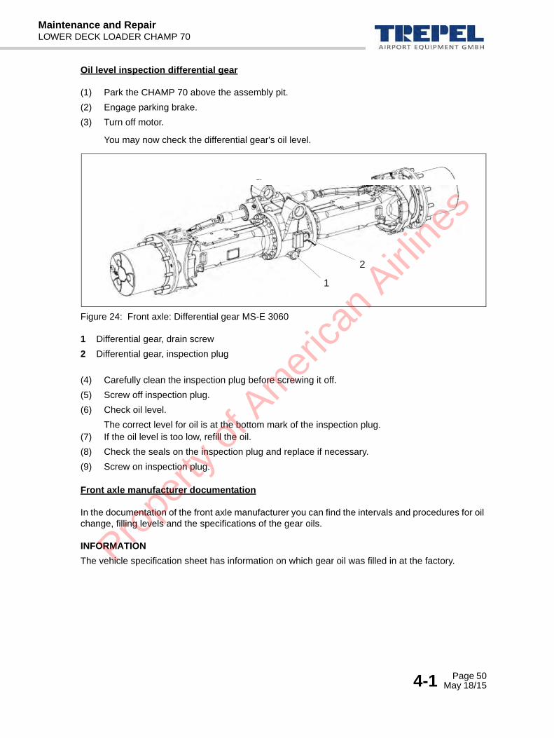
Oil level inspection differential gear
(1) Park the CHAMP 70 above the assembly pit.
(2) Engage parking brake.
(3) Turn off motor.
You may now check the differential gear's oil level.
Figure 24: Front axle: Differential gear MS-E 3060
1 Differential gear, drain screw
2 Differential gear, inspection plug
(4) Carefully clean the inspection plug before screwing it off.
(5) Screw off inspection plug.
(6) Check oil level.
The correct level for oil is at the bottom mark of the inspection plug.(7) If the oil level is too low, refill the oil.
(8) Check the seals on the inspection plug and replace if necessary.
(9) Screw on inspection plug.
Front axle manufacturer documentation
In the documentation of the front axle manufacturer you can find the intervals and procedures for oil change, filling levels and the specifications of the gear oils.
INFORMATION
The vehicle specification sheet has information on which gear oil was filled in at the factory.
1
2
Prope
rty o
f Am
erica
n Airli
nes
Page 504-1 May 18/15
Maintenance and Repair LOWER DECK LOADER CHAMP 70
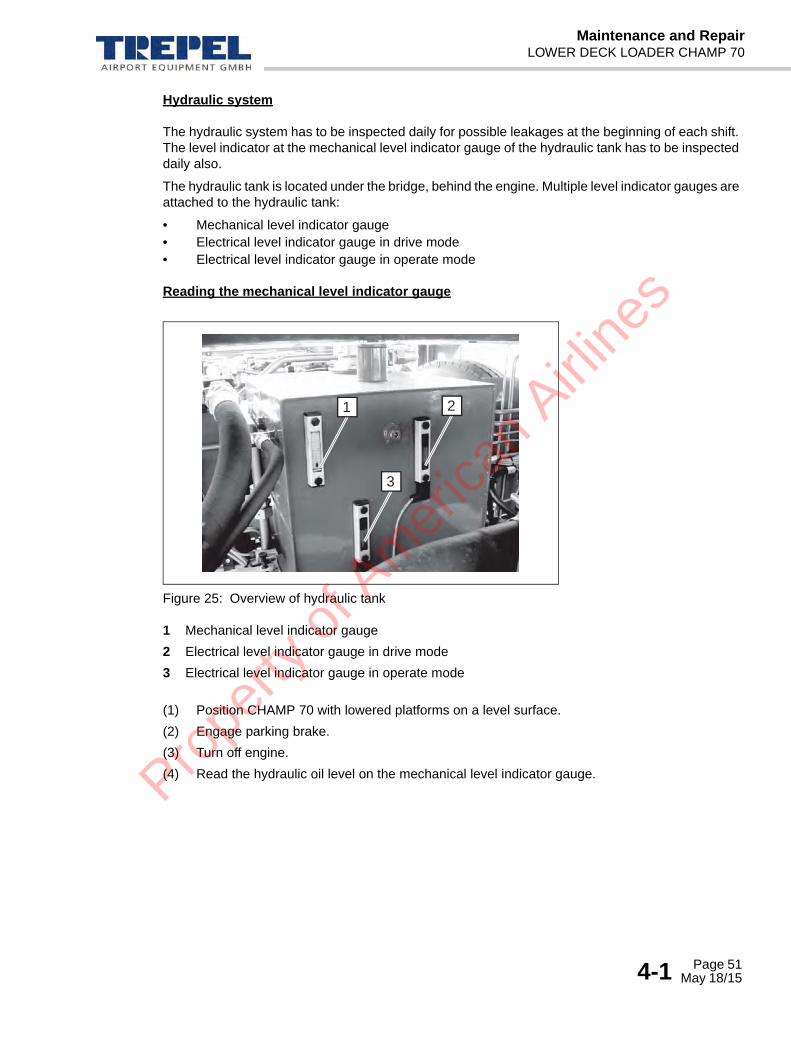
Hydraulic system
The hydraulic system has to be inspected daily for possible leakages at the beginning of each shift. The level indicator at the mechanical level indicator gauge of the hydraulic tank has to be inspected daily also.
The hydraulic tank is located under the bridge, behind the engine. Multiple level indicator gauges are attached to the hydraulic tank:
• Mechanical level indicator gauge• Electrical level indicator gauge in drive mode• Electrical level indicator gauge in operate mode
Reading the mechanical level indicator gauge
Figure 25: Overview of hydraulic tank
1 Mechanical level indicator gauge
2 Electrical level indicator gauge in drive mode
3 Electrical level indicator gauge in operate mode
(1) Position CHAMP 70 with lowered platforms on a level surface.
(2) Engage parking brake.
(3) Turn off engine.
(4) Read the hydraulic oil level on the mechanical level indicator gauge.
1 2
3
Prope
rty o
f Am
erica
n Airli
nes
Page 514-1 May 18/15

Maintenance and RepairLOWER DECK LOADER CHAMP 70
Figure 26: Mechanical level indicator of the hydraulic tank
1 Mechanical level indicator gauge
2 Upper marking
3 Hydraulic oil temperature gauge
4 Lower marking
The hydraulic oil level should be in the upper range of the level indicator when the engine is switched off, the platforms are lowered and the stabilizers are retracted.
The oil level may not be above the upper mark.
The oil level may also not be below the lower mark. If the oil level is too low, the cause for the loss of oil has to be found and the error rectified.
Only once the cause for the oil loss has been found and the error rectified can the oil be refilled.
1
2
3
4
Prope
rty o
f Am
erica
n Airli
nes
Page 524-1 May 18/15

Maintenance and Repair LOWER DECK LOADER CHAMP 70
Refill oil
Figure 27: Oil filler tubes closed/opened
(1) Unscrew oil filler tubes.
(2) Refill hydraulic oil.
INFORMATION
Use a hydraulic oil for the hydraulic system that conforms to the specification HLP-ISO-VG. Do not mix hydraulic oils with different specifications.
The vehicle specification sheet has information on which hydraulic oil was filled in at the factory.
(3) Close the tank with the oil filler tube.
Oil level inspection electrical level indicator gauge
Both electrical level indicator gauges are not read at the hydraulic tank. During the operation red con-trol lights illuminate on the instrument panel and the operating panel of the driver's stand in case of too low hydraulic oil levels.
The red engine warning light lights up if the hydraulic level is too low in operate mode.
The red engine warning light lights up if the hydraulic level is too low in drive mode.
If the red engine warning light lights up, do not continue to work with the CHAMP 70. Immediately lower all platforms, shut down the CHAMP 70 and inspect it for the cause of the oil loss.
Only once the cause for the oil loss has been found and the error rectified can the oil be refilled.Prope
rty o
f Am
erica
n Airli
nes
Page 534-1 May 18/15

Maintenance and RepairLOWER DECK LOADER CHAMP 70
Refill oil
(1) Unscrew oil filler tubes.
(2) Refill hydraulic oil.
INFORMATION
Use a hydraulic oil for the hydraulic system that conforms to the specification HLP-ISO-VG. Do not mix hydraulic oils with different specifications.
The vehicle specification sheet has information on which hydraulic oil was filled in at the factory.
(3) Close the tank with the oil filler tube.
Prope
rty o
f Am
erica
n Airli
nes
Page 544-1 May 18/15

Maintenance and Repair LOWER DECK LOADER CHAMP 70
F. Maintenance on the motor
Figure 28: Overview - Motor
1 Speed regulator
2 Dry air filter
3 Motor bearings
Motor damages!
Neglected or improperly carried out maintenance tasks can cause danger to the motor.
The content of the maintenance instructions of the motor manufacturer need to be known to the service personnel and be applied by them.
All maintenance and repair instructions of the motor manufacturer have to be strictly complied with.
Maintenance and repair work is only to be performed by fully trained, qualified, and author-ized service personnel.
2
1
3
Prope
rty o
f Am
erica
n Airli
nes
Page 554-1 May 18/15

Maintenance and RepairLOWER DECK LOADER CHAMP 70
Figure 29: Instruction signs on engine maintenance intervals
Documentation of the motor manufacturer
You will find support to the following maintenance tasks in the documentation of the motor manufac-turer:
• Lubrication system• Fuel system• Cooling system• Dry air filter• Belt drives• Setting tasks• Attached parts• Spare parts
Prope
rty o
f Am
erica
n Airli
nes
Page 564-1 May 18/15

Maintenance and Repair LOWER DECK LOADER CHAMP 70
Checking the speed boost setting
The engine must be running for setting the speed boost. This means that an additional person must be present on the driver's stand to ensure the safety of the person working on the engine.
Strictly observe the following safety instructions:
Danger of poisoning!
In closed rooms the exhausts of the running motors can poison or suffocate the service personnel.
Inhalation of noxious exhaust fumes can lead to serious injury and even death.
Always ensure good ventilation of the workshop or connect an exhaust hose to the exhaust pipe of the engine.
Running over persons!
When the motor is running, the CHAMP 70 can suddenly run over service personnel.
A collision with the CHAMP 70 can cause life threatening injuries and even death.
Always engage the parking brake or place blocks under the wheels.
While the engine is running, a person must be present on the driver's stand to monitor the CHAMP 70.
Lowering platform!
During work on the CHAMP 70, the platforms can suddenly lower and crush service personnel.
Platforms can suddenly lower and cause serious injury and even death.
Never work under unsecured platforms.
Lower the elevator completely.
Secure the raised bridge with maintenance blocks.
Prope
rty o
f Am
erica
n Airli
nes
Page 574-1 May 18/15
Maintenance and RepairLOWER DECK LOADER CHAMP 70
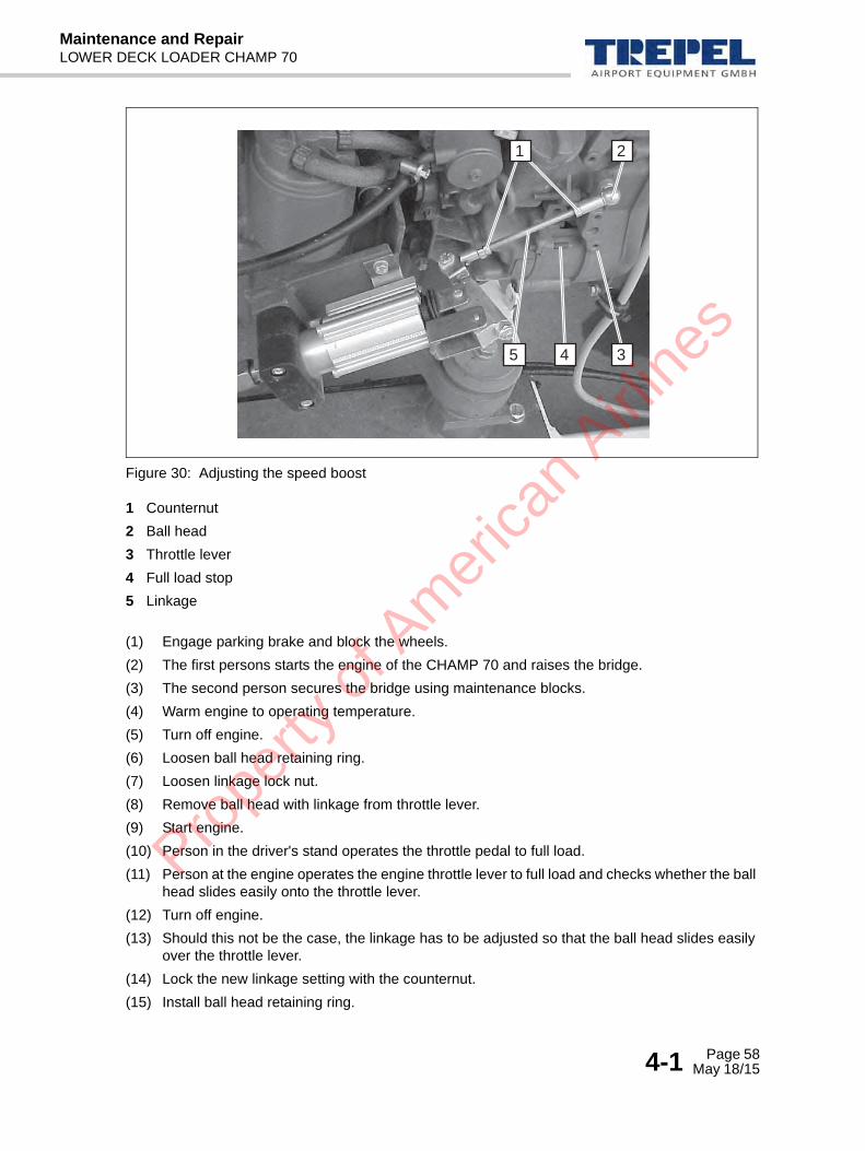
Figure 30: Adjusting the speed boost
1 Counternut
2 Ball head
3 Throttle lever
4 Full load stop
5 Linkage
(1) Engage parking brake and block the wheels.
(2) The first persons starts the engine of the CHAMP 70 and raises the bridge.
(3) The second person secures the bridge using maintenance blocks.
(4) Warm engine to operating temperature.
(5) Turn off engine.
(6) Loosen ball head retaining ring.
(7) Loosen linkage lock nut.
(8) Remove ball head with linkage from throttle lever.
(9) Start engine.
(10) Person in the driver's stand operates the throttle pedal to full load.
(11) Person at the engine operates the engine throttle lever to full load and checks whether the ball head slides easily onto the throttle lever.
(12) Turn off engine.
(13) Should this not be the case, the linkage has to be adjusted so that the ball head slides easily over the throttle lever.
(14) Lock the new linkage setting with the counternut.
(15) Install ball head retaining ring.
1
345
2
Prope
rty o
f Am
erica
n Airli
nes
Page 584-1 May 18/15

Maintenance and Repair LOWER DECK LOADER CHAMP 70
Checking the motor bearings
Check the motor bearings annually.
Figure 31: Motor bearings
(1) Carry out a visual inspection of the elastic bearing parts of the motor.
(2) Look for deformation, damages, and cracks.
(3) Check the firm seat of the bearing screws.
INFORMATION
Replace defective bearing parts always in pairs.
Prope
rty o
f Am
erica
n Airli
nes
Page 594-1 May 18/15

Maintenance and RepairLOWER DECK LOADER CHAMP 70
G. Maintenance on Wheels/Axles/Steering/Brakes
The following contains information about maintenance of the wheels, and mounting and dismounting the wheels.
The following gives you a short list of the necessary maintenance work on the front axle.
Wheels and tires
The condition of the wheels and tires is very important for the operating safety of the CHAMP 70.
Accident danger!
Negligence and improperly executed work on wheels and tires impair the operating safety of the CHAMP 70 and can lead to severe accidents.
Accidents due to insufficient maintenance of wheels can lead to severely damaged persons or even death.
Regularly check wheels and tires for damage and trend thickness.
Defective wheels and wheels with too little tread profile have to be replaced immediately.
Repair work on wheely and tires may only be executed by qualified technicians.
Check wheels and tires
Inspect the tires and wheels of the CHAMP 70 before shift change for
• visible damage of tires,• sufficient profile depth,• foreign objects in the tire profile• Damaged wheel rims• Missing or loose wheel bolts/wheel nuts.
Inspecting tightening torques of front wheels
INFORMATION
The tightening torque is 500 Nm (11,865 pdl ft).
(1) Inspect the tightness of the wheel nuts every 250 operating hours.
(2) If the wheels have been newly mounted, check after 10 operating hours.
(3) Use a torque wrench to tighten the wheel nuts. Make sure to use the correct tightening torque.
Prope
rty o
f Am
erica
n Airli
nes
Page 604-1 May 18/15

Maintenance and Repair LOWER DECK LOADER CHAMP 70
Preparations for removing the front wheel
The CHAMP 70 has to be placed onto timber supports for dismounting the front wheels. For this, the CHAMP 70 must be lifted and lowered onto the scantlings.
There are various means of lifting the CHAMP 70, as follows:
• Variant 1: lifting the CHAMP 70 using a crane• Variant 2: lifting the CHAMP 70 using hydraulic jacks with claws• Variant 3: Lifting the CHAMP 70 using pneumatic jacks
Requirements:
• CHAMP 70 stands on an even and firm surface.• Parking brake is engaged.• Stabilizers are extended.• Motor is turned off.
Lifting or placing the CHAMP 70 on support blocks in an improper manner!
The chassis of the CHAMP 70 can bend by lifting or supporting it on one side.
Always lift and support the CHAMP 70 evenly.
Prope
rty o
f Am
erica
n Airli
nes
Page 614-1 May 18/15

Maintenance and RepairLOWER DECK LOADER CHAMP 70
Variant 1: lifting the CHAMP 70 using a crane
Read the transport instruction manual before lifting the CHAMP 70 and strictly follow the instructions.
(1) Lifting the CHAMP 70.
Figure 32: Diagram: Lifting the CHAMP 70 and lowering it on scantlings
1 Scantling 4 000 x 150 x 300 mm (157 ½ x 6 x 11 ¾ inches)
2 Scantling 4 000 x 150 x 190 mm (157 ½ x 6 x 7 ½ inches)
(2) Lower the CHAMP 70 onto the timber supports.
The front wheel can now be dismounted, see Subsection "Dismounting the front wheel", page 68.
ca. 10 500 kg (approx. 23 150 lb) ca. 10 500 kg (approx. 23 150 lb)
1 2
Prope
rty o
f Am
erica
n Airli
nes
Page 624-1 May 18/15

Maintenance and Repair LOWER DECK LOADER CHAMP 70
Variant 2: Lifting the CHAMP 70 using hydraulic jacks
To lift the CHAMP 70, two hydraulic jacks with claws each with a lifting capacity of at least 10 000 kg (22,046 lb) must be used.
Impermissible hoists!
If impermissible hoists are used, the chassis can unexpectedly drop down when being placed on support blocks. This can crush persons under the CHAMP 70.
The crush injuries can be life-threatening or even fatal.
Ensure that only lifting equipment with sufficient lifting capacity is used.
Before lifting the CHAMP 70 with lifting equipment, read the manufacturer's documentation and adhere strictly to the instructions.
Two persons are needed for lifting the CHAMP 70.
Figure 33: Diagram: placing hydraulic jacks at one longitudinal side of the chassis
1 Hydraulic jacks with claws with a lifting capacity of at least 10 000 kg (22,046 lb)
(1) Secure the rear wheels with stop blocks.
(2) Place hydraulic jack at the front and the middle of the longitudinal side of the CHAMP 70.
INFORMATION
In each case, a load-bearing part of the chassis must run through the point of support.
The lifting claw must always grip completely below the chassis.
1
Prope
rty o
f Am
erica
n Airli
nes
Page 634-1 May 18/15

Maintenance and RepairLOWER DECK LOADER CHAMP 70
(3) Using the jacks, lift the CHAMP 70 at the same time and evenly at the front and the middle using two persons.
Figure 34: Diagram: lowering the CHAMP 70 onto supports using hydraulic jacks
1 Hydraulic jack at the longitudinal side, front
2 Support (e.g. scantling, height = 300 mm (11 ¾ inches)
3 Hydraulic jack at the longitudinal side, rear
4 Support (e.g. scantling, height = 190 mm (7 ½ inches)
(4) Underlay the chassis at the support points with suitable supports made from steel or hardwood with a slip-resistant surface.
Support point, front: Support with a height of 300 mm (11 ¾ inches).Support point, rear: Support with a height of 190 mm (7 ½ inches).
(5) Lower the CHAMP 70 evenly onto the supports.
The front wheel can now be dismounted, see Subsection "Dismounting the front wheel", page 68.
1 2 3 4
Prope
rty o
f Am
erica
n Airli
nes
Page 644-1 May 18/15
Maintenance and Repair LOWER DECK LOADER CHAMP 70
Variant 3: Lifting the CHAMP 70 using pneumatic jacks
For lifting the CHAMP 70, two pneumatic jacks each with a lifting capacity of at least 8 000 kg (17,640 lb) must be used.
Impermissible hoists!
If impermissible hoists are used, the chassis can unexpectedly drop down when being placed on support blocks. This can crush persons under the CHAMP 70.
The crush injuries can be life-threatening or even fatal.
Ensure that only lifting equipment with sufficient lifting capacity is used.
Before lifting the CHAMP 70 with lifting equipment, read the manufacturer's documentation and adhere strictly to the instructions.
Two persons are needed for lifting the CHAMP 70.
Prope
rty o
f Am
erica
n Airli
nes
Page 654-1 May 18/15
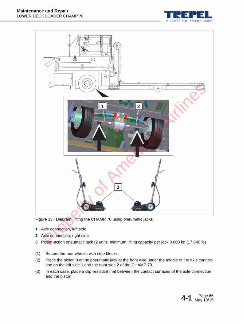
Maintenance and RepairLOWER DECK LOADER CHAMP 70
Figure 35: Diagram: lifting the CHAMP 70 using pneumatic jacks
1 Axle connection, left side
2 Axle connection, right side
3 Piston-action pneumatic jack (2 units, minimum lifting capacity per jack 8 000 kg (17,640 lb)
(1) Secure the rear wheels with stop blocks.
(2) Place the piston 3 of the pneumatic jack at the front axle under the middle of the axle connec-tion on the left side 1 and the right side 2 of the CHAMP 70.
(3) In each case, place a slip-resistant mat between the contact surfaces of the axle connection and the piston.
3
1 2
Prope
rty o
f Am
erica
n Airli
nes
Page 664-1 May 18/15

Maintenance and Repair LOWER DECK LOADER CHAMP 70
INFORMATION
The contact surfaces of the axle connection must lie completely on the contact surface of the pis-tons.
(4) Using the jacks, lift the CHAMP 70 at the same time and evenly at the left and the right using two persons.
Figure 36: Diagram: lowering the CHAMP 70 onto supports using pneumatic jacks
1 Support, front support point (e.g. scantling), height = 300 mm (11 ¾ inches)
2 Support, rear support point (e.g. scantling), height = 190 mm (7 ½ inches)
(5) Underlay the chassis at the support points of both longitudinal sides with suitable supports made from steel or hardwood with a slip-resistant surface.
Support points, front: Support with a height of 300 mm (11 ¾ inches).Support points, rear: Support with a height of 190 mm (7 ½ inches).
(6) Lower the CHAMP 70 evenly onto the supports.
The front wheel can now be dismounted, see Subsection "Dismounting the front wheel", page 68.
1 2
Prope
rty o
f Am
erica
n Airli
nes
Page 674-1 May 18/15
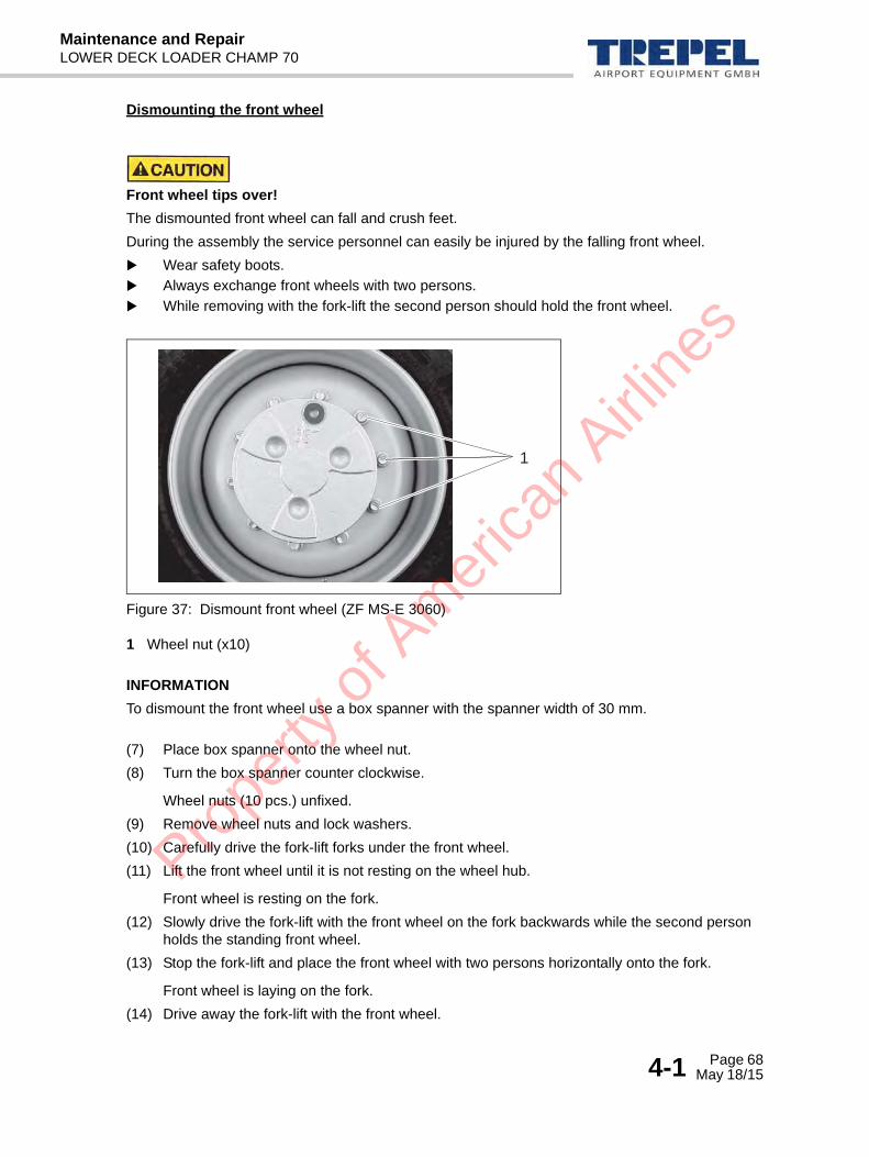
Maintenance and RepairLOWER DECK LOADER CHAMP 70
Dismounting the front wheel
Front wheel tips over!
The dismounted front wheel can fall and crush feet.
During the assembly the service personnel can easily be injured by the falling front wheel.
Wear safety boots.
Always exchange front wheels with two persons.
While removing with the fork-lift the second person should hold the front wheel.
Figure 37: Dismount front wheel (ZF MS-E 3060)
1 Wheel nut (x10)
INFORMATION
To dismount the front wheel use a box spanner with the spanner width of 30 mm.
(7) Place box spanner onto the wheel nut.
(8) Turn the box spanner counter clockwise.
Wheel nuts (10 pcs.) unfixed.
(9) Remove wheel nuts and lock washers.
(10) Carefully drive the fork-lift forks under the front wheel.
(11) Lift the front wheel until it is not resting on the wheel hub.
Front wheel is resting on the fork.
(12) Slowly drive the fork-lift with the front wheel on the fork backwards while the second person holds the standing front wheel.
(13) Stop the fork-lift and place the front wheel with two persons horizontally onto the fork.
Front wheel is laying on the fork.
(14) Drive away the fork-lift with the front wheel.
1
Prope
rty o
f Am
erica
n Airli
nes
Page 684-1 May 18/15

Maintenance and Repair LOWER DECK LOADER CHAMP 70
Mounting the front wheel
(1) Bring the fork-lift with the new or repaired front wheel to the CHAMP 70.
(2) Two persons place the front wheel onto the fork.
(3) One person holds the standing front wheel.
(4) The second person operates the fork-lift and raises the front wheel onto the wheel hub.
INFORMATION
Make sure that the bore holes of the front wheel are aligned with the wheel bolts of the wheel hub. If necessary, turn the front wheel until the bore holes are aligned with the wheel hub.
(5) Push the front wheel with the bore holes carefully onto the wheel bolts.
Front wheel is correctly positioned on the wheel hub.
Property damage!
The wheel bolts can be damaged during the mounting of the front wheel to the wheel hub.
Push the front wheel onto the wheel hub with care.
(6) Push the lock washers onto the wheel bolts.
(7) Screw the wheel nuts manually.
(8) Drive the fork-lift away backwards.
Figure 38: Order for tightening
INFORMATION
The tightening torque is 500 Nm (11,865 pdl ft).
Prope
rty o
f Am
erica
n Airli
nes
Page 694-1 May 18/15

Maintenance and RepairLOWER DECK LOADER CHAMP 70
(9) Use a torque wrench to tighten the wheel nuts. Make sure to tighten the nuts in the correct order and use the correct tightening torque.
The front wheel is now mounted.
(10) Lift the CHAMP 70 with a crane.
(11) Remove planks.
(12) Place the CHAMP 70 onto the ground.
CHAMP 70 is now ready for operation.
INFORMATION
After 10 operating hours the tightening torque of the wheel nuts should be checked with the torque wrench and tightened if necessary.
Prope
rty o
f Am
erica
n Airli
nes
Page 704-1 May 18/15

Maintenance and Repair LOWER DECK LOADER CHAMP 70
Dismounting the rear wheel
To remove the rear wheels, the CHAMP 70 be jacked up. For this, the CHAMP 70 must be lifted using a forklift and placed on support stands.
Requirements:
• CHAMP 70 stands on an even and firm surface.• Parking brake is engaged.• Stabilizers are extended.• Motor is turned off.
Lifting the CHAMP 70 in an improper manner!
If the CHAMP 70 is lifted with the forklift in an improper manner, the chassis can be bent.
Make sure the transverse beam of the chassis is supported on both forks of the forklift.
Securing the CHAMP 70
(1) Start the engine.
(2) Lift the bridge.
(3) Place maintenance stabilizers at the bridge (see Subsection C "Secure raised platform", page 30).
(4) Lift the elevator.
(5) Place maintenance stabilizers at the elevator (see Subsection C "Secure raised platform", page 30).
(6) Turn off the engine and secure the front wheels of the CHAMP 70 with stop blocks.
Prope
rty o
f Am
erica
n Airli
nes
Page 714-1 May 18/15
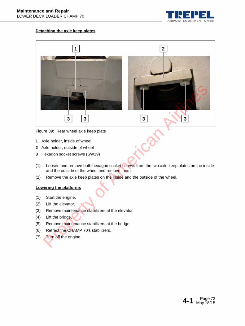
Maintenance and RepairLOWER DECK LOADER CHAMP 70
Detaching the axle keep plates
Figure 39: Rear wheel axle keep plate
1 Axle holder, inside of wheel
2 Axle holder, outside of wheel
3 Hexagon socket screws (SW19)
(1) Loosen and remove both hexagon socket screws from the two axle keep plates on the inside and the outside of the wheel and remove them.
(2) Remove the axle keep plates on the inside and the outside of the wheel.
Lowering the platforms
(1) Start the engine.
(2) Lift the elevator.
(3) Remove maintenance stabilizers at the elevator.
(4) Lift the bridge.
(5) Remove maintenance stabilizers at the bridge.
(6) Retract the CHAMP 70's stabilizers.
(7) Turn off the engine.
1
3333
2
Prope
rty o
f Am
erica
n Airli
nes
Page 724-1 May 18/15
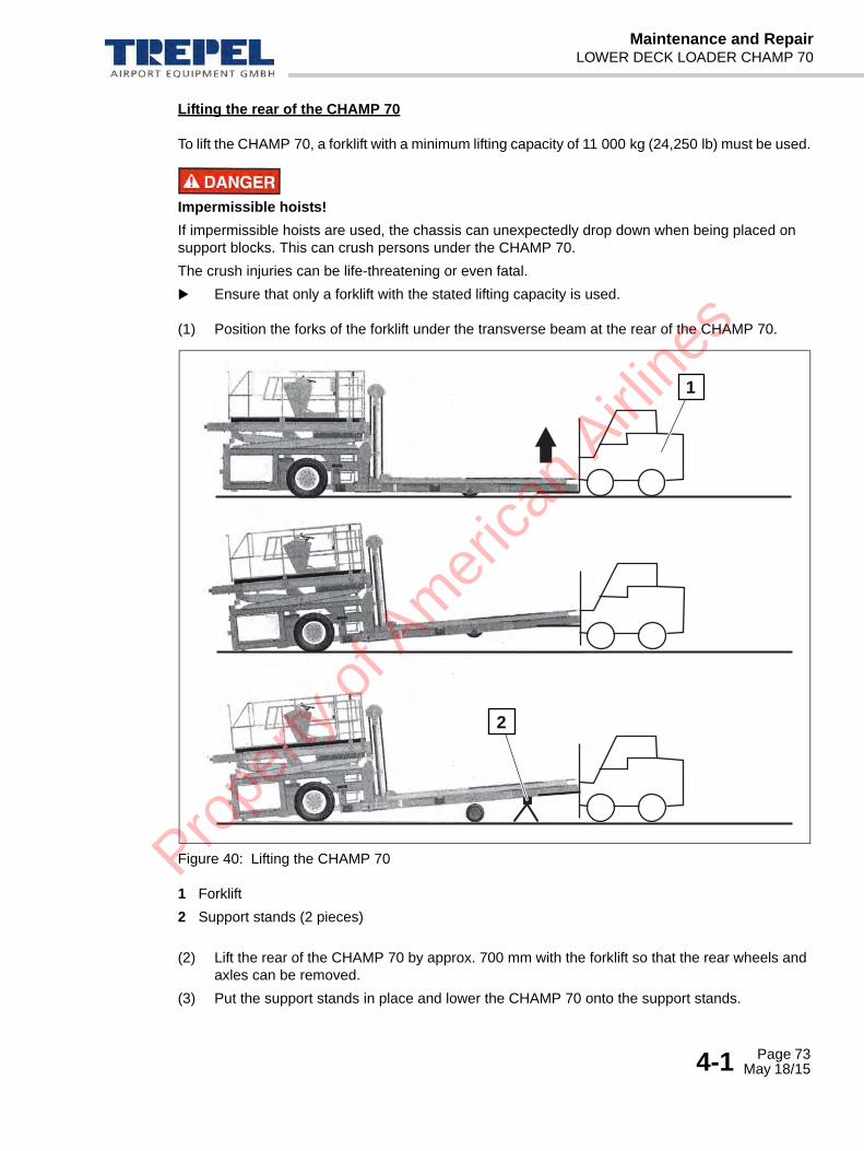
Maintenance and Repair LOWER DECK LOADER CHAMP 70
Lifting the rear of the CHAMP 70
To lift the CHAMP 70, a forklift with a minimum lifting capacity of 11 000 kg (24,250 lb) must be used.
Impermissible hoists!
If impermissible hoists are used, the chassis can unexpectedly drop down when being placed on support blocks. This can crush persons under the CHAMP 70.
The crush injuries can be life-threatening or even fatal.
Ensure that only a forklift with the stated lifting capacity is used.
(1) Position the forks of the forklift under the transverse beam at the rear of the CHAMP 70.
Figure 40: Lifting the CHAMP 70
1 Forklift
2 Support stands (2 pieces)
(2) Lift the rear of the CHAMP 70 by approx. 700 mm with the forklift so that the rear wheels and axles can be removed.
(3) Put the support stands in place and lower the CHAMP 70 onto the support stands.
2
1
Prope
rty o
f Am
erica
n Airli
nes
Page 734-1 May 18/15

Maintenance and RepairLOWER DECK LOADER CHAMP 70
(4) Remove the rear wheels and axles.
The rear wheels are detached and new wheels can now be attached to the axle.
INFORMATION
The rear wheel must be replaced in the reverse order.
After replacing the wheel, ensure that the screws of the axle keep plate are tightened to the correct torque (see Subsection "Screws of supporting parts and flanges", page 17)
Loosening of wheel nuts!
After a wheel change, the wheel nuts can loosen due to material settling and lead to serious acci-dents.
Persons can be seriously injured or even killed because of serious accidents.
Be sure to retighten all wheel nuts with the specified tightening torque after the wheel exchange.
Retighten the wheel nuts with the prescribed tightening torque again after the first laden jour-ney, at the latest after 24 operating hours.
Prope
rty o
f Am
erica
n Airli
nes
Page 744-1 May 18/15
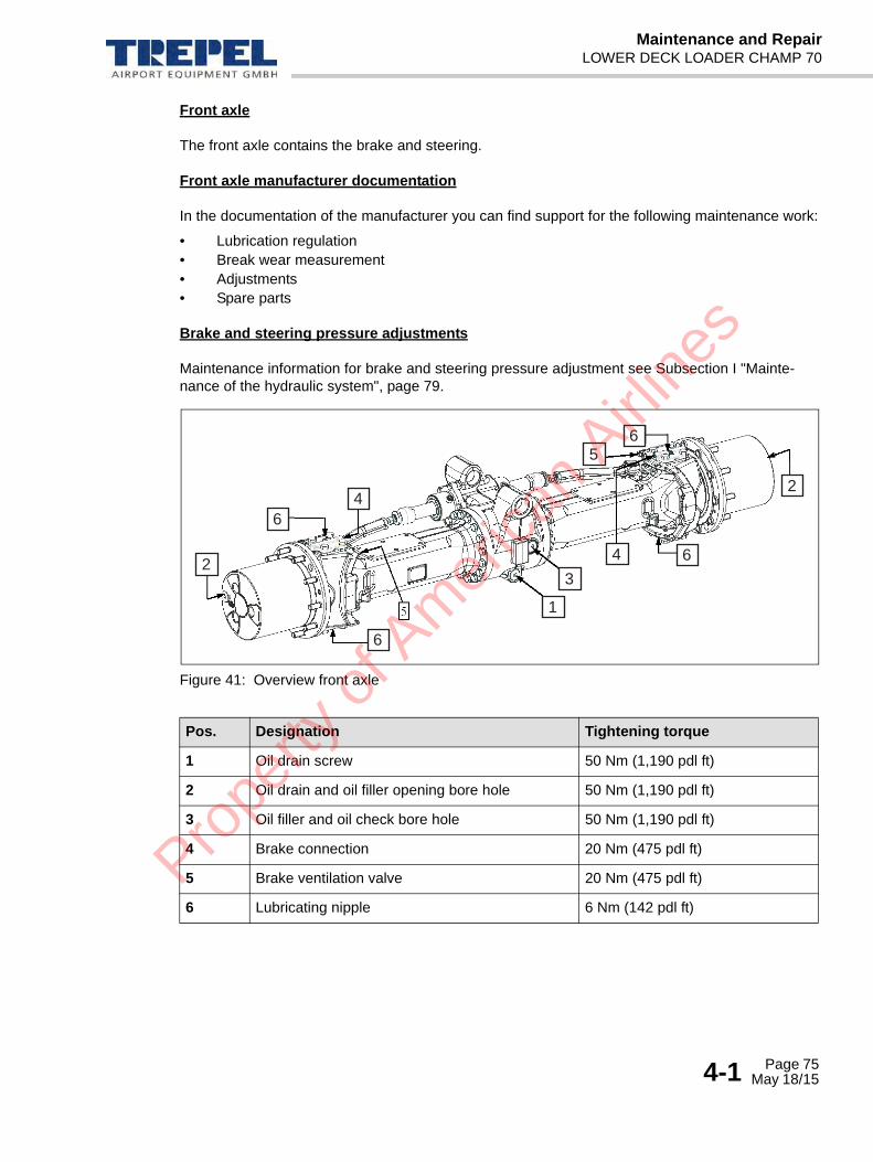
Maintenance and Repair LOWER DECK LOADER CHAMP 70
Front axle
The front axle contains the brake and steering.
Front axle manufacturer documentation
In the documentation of the manufacturer you can find support for the following maintenance work:
• Lubrication regulation• Break wear measurement• Adjustments• Spare parts
Brake and steering pressure adjustments
Maintenance information for brake and steering pressure adjustment see Subsection I "Mainte-nance of the hydraulic system", page 79.
Figure 41: Overview front axle
Pos. Designation Tightening torque
1 Oil drain screw 50 Nm (1,190 pdl ft)
2 Oil drain and oil filler opening bore hole 50 Nm (1,190 pdl ft)
3 Oil filler and oil check bore hole 50 Nm (1,190 pdl ft)
4 Brake connection 20 Nm (475 pdl ft)
5 Brake ventilation valve 20 Nm (475 pdl ft)
6 Lubricating nipple 6 Nm (142 pdl ft)
23
4
1
4
2
5
6
6
6
6
Prope
rty o
f Am
erica
n Airli
nes
Page 754-1 May 18/15

Maintenance and RepairLOWER DECK LOADER CHAMP 70
H. Maintenance on the platforms / transport system
Pay attention to the general accident prevention regulations when performing maintenance, repair, and adjustment work.
Lowering platform!
When working under the platform the service personnel can be crushed by lowering platforms.
The lowering platform can cause serious injuries or even death to the service personnel.
Never work under unsecured platforms.
Turn off the engine.
Check the cargo safety equipment.
Secure the raised platforms with maintenance blocks.
Rolling CHAMP 70!
If the parking brake is not engaged, the CHAMP 70 can roll and run over service personnel.
A collision with the rolling CHAMP 70 can cause life threatening injuries and even death.
Ensure that the parking brake is engaged during maintenance work.
Ensure that blocks have been placed under the wheels.
Performed work
• Lubrication• Hydraulic/electro-hydraulic checks and adjustments• Visual inspection of mechanical, electrical, and hydraulic components
(1) Lubricate the lubrication points on the platforms and on the transport system (see Subsection D "Lubricating points", page 34).
(2) Perform hydraulic and electro-hydraulic checks and adjustments according to the mainte-nance schedule and Subsection I "Maintenance of the hydraulic system", page 79.
(3) Check that the cargo stops are firmly attached.
(4) Check mobility.
(5) Check cargo stops for damage.
INFORMATION
Replace cargo stops if damaged.Prope
rty o
f Am
erica
n Airli
nes
Page 764-1 May 18/15

Maintenance and Repair LOWER DECK LOADER CHAMP 70
Lift chain maintenance
Figure 42: Lift chains (double chain is optional)
Prope
rty o
f Am
erica
n Airli
nes
Page 774-1 May 18/15

Maintenance and RepairLOWER DECK LOADER CHAMP 70
Figure 43: Lift chain tension (double chain is optional)
1 Safety chain
2 Lift chain
3 Jam nut SW 46
4 Adjusting nut SW 46
5 Counter nut SW 46
6 Safety chain fastener (disk spring package)
7 Threaded rod M30
Checking the lift chains
INFORMATION
The lift chains are stretched chains that do not lengthen.
(1) Perform a visual inspection of the chain links for damage.
(2) Check lift chain tension.
(3) Check that the counter nut and jam nut on the threaded rod M30 are securely fastened.
Adjusting the double chain (optional)
(1) Adjust the double chain as per Figure "Lift chains (double chain is optional)".
1
2
5
3
5
5
3
4
6
3
7
Prope
rty o
f Am
erica
n Airli
nes
Page 784-1 May 18/15

Maintenance and Repair LOWER DECK LOADER CHAMP 70
I. Maintenance of the hydraulic system
This chapter informs you about the maintenance intervals of the hydraulic system.
You receive information about the inspection and setting work of the flow control valves and the dif-ferent pressures in the hydraulic system.
Leaking hydraulic oil!
The hydraulic oil is under pressure. Suddenly emerging hydraulic oil can squirt into the eyes and injure other body parts.
Hydraulic oil emerging under pressure can seriously injure the service personnel.
Depressurize the hydraulic system before performing maintenance on it.
Wear protective goggles when performing any adjustments or inspections.
Regularly check hydraulic lines and hoses for leakage, proper positioning and porosity, repair and replace hydraulic hoses where necessary.
Harmful to the environment!
Leaking hydraulic oil pollutes the soil and the ground water.
Close all openings with protective caps or rubber stoppers.
Immediately catch leaking oil and dispose of in accordance with the laws and regulations.
Depressurising the hydraulic system
INFORMATION
The hydraulic system is depressurized by closing the shut-off cock of the hydraulic tank before beginning the maintenance and repair work.
The engine does not start when the shut-off cock is closed.
Requirements
Before you depressurize the hydraulic system, the following conditions need to be met:
• CHAMP 70 stands on an even and firm surface.• Both platforms are lowered.• No cargo is located on the platform.• Parking brake is engaged.• Wheels are blocked by blocks.• Motor is turned off.Pro
perty
of A
mer
ican
Airline
s
Page 794-1 May 18/15
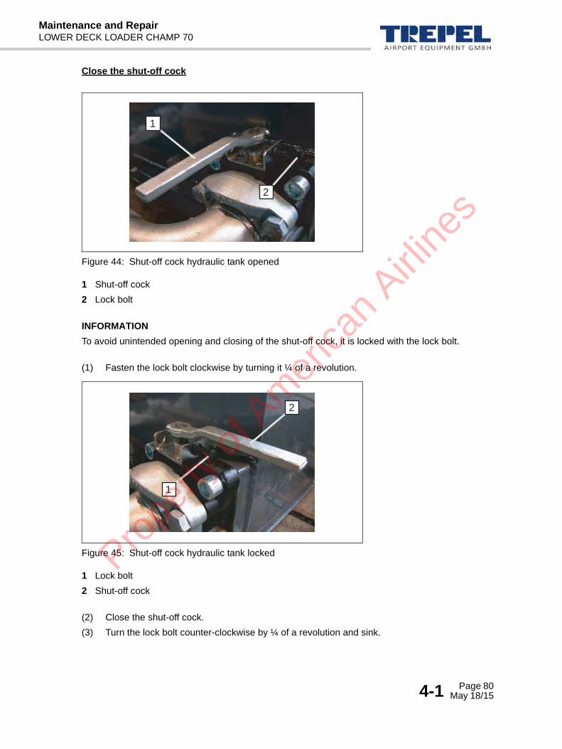
Maintenance and RepairLOWER DECK LOADER CHAMP 70
Close the shut-off cock
Figure 44: Shut-off cock hydraulic tank opened
1 Shut-off cock
2 Lock bolt
INFORMATION
To avoid unintended opening and closing of the shut-off cock, it is locked with the lock bolt.
(1) Fasten the lock bolt clockwise by turning it ¼ of a revolution.
Figure 45: Shut-off cock hydraulic tank locked
1 Lock bolt
2 Shut-off cock
(2) Close the shut-off cock.
(3) Turn the lock bolt counter-clockwise by ¼ of a revolution and sink.
2
1
2
1
Prope
rty o
f Am
erica
n Airli
nes
Page 804-1 May 18/15

Maintenance and Repair LOWER DECK LOADER CHAMP 70
Check hydraulic system
Pump and engine manufacturer documentation
In the maintenance manual for the pump and hydraulic engine you can find the maintenance inter-vals and the procedures for maintenance.
Material damage!
During the maintenance work dirt may inter the hydraulic system and damage the pumps and hydraulic engines.
Thoroughly clean the surrounding area before removing the screws and hoses.
Close all openings with protective caps or rubber stoppers.
Interval Maintenance work
Daily Perform visual inspection of the hydraulic system for leakages. Also check the contamination indicators of the filters. In case of oil traces on the floor, immediately check the oil level of the hydraulic tank.
Every 250 operating hours Check the hydraulic lines and hoses for leakage, proper posi-tioning and porosity. Remove leakages and replace porous or defect hydraulic hoses. Replace hydraulic hoses no later than every 5 years.
Every 500 operating hours Check the entire hydraulic system for leakages. Check the armatures for leakages and replace defective armatures.
Check hydraulic cylinders for leakages and firm positioning of the screw connections. Replace faulty parts.
At least once a year Perform hydraulic oil change including filter change. Unless the contamination indicator is in the red range, then the filter change and hydraulic oil change is due before the annual inter-val is over.
Prope
rty o
f Am
erica
n Airli
nes
Page 814-1 May 18/15
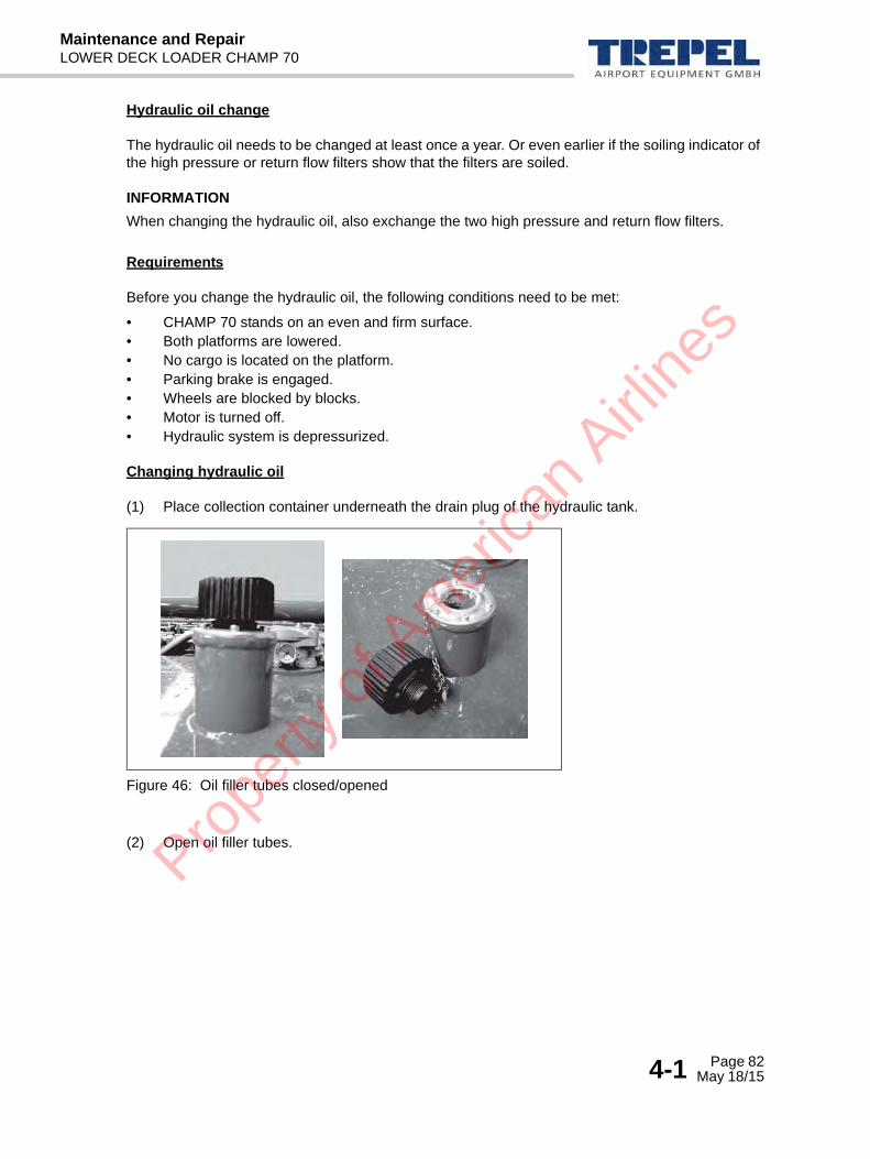
Maintenance and RepairLOWER DECK LOADER CHAMP 70
Hydraulic oil change
The hydraulic oil needs to be changed at least once a year. Or even earlier if the soiling indicator of the high pressure or return flow filters show that the filters are soiled.
INFORMATION
When changing the hydraulic oil, also exchange the two high pressure and return flow filters.
Requirements
Before you change the hydraulic oil, the following conditions need to be met:
• CHAMP 70 stands on an even and firm surface.• Both platforms are lowered.• No cargo is located on the platform.• Parking brake is engaged.• Wheels are blocked by blocks.• Motor is turned off.• Hydraulic system is depressurized.
Changing hydraulic oil
(1) Place collection container underneath the drain plug of the hydraulic tank.
Figure 46: Oil filler tubes closed/opened
(2) Open oil filler tubes.
Prope
rty o
f Am
erica
n Airli
nes
Page 824-1 May 18/15

Maintenance and Repair LOWER DECK LOADER CHAMP 70
Figure 47: Drain screw
INFORMATION
To unscrew the drain screws use a flat spanner with the spanner width 19 mm.
(3) Unscrew the drain screw with a flat spanner.
(4) Fully drain the oil.
(5) Clean the drain plug with a lint-free cloth.
(6) Put a new seal on the drain plug.
(7) Screw the drain plug back in and screw tight.
(8) Fill with oil.
INFORMATION
Use a hydraulic oil for the hydraulic system that conforms to the specification HLP-ISO-VG. Do not mix hydraulic oils with different specifications.
INFORMATION
The vehicle specification sheet has information on which hydraulic oil was filled in at the factory.
Prope
rty o
f Am
erica
n Airli
nes
Page 834-1 May 18/15
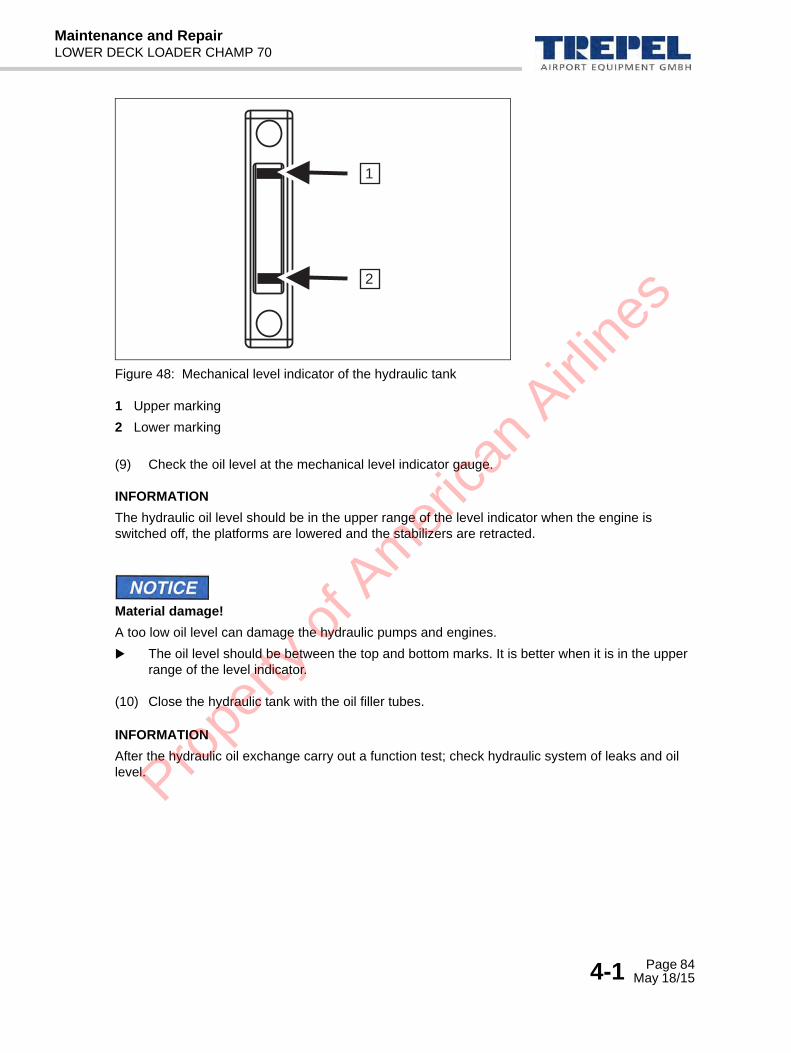
Maintenance and RepairLOWER DECK LOADER CHAMP 70
Figure 48: Mechanical level indicator of the hydraulic tank
1 Upper marking
2 Lower marking
(9) Check the oil level at the mechanical level indicator gauge.
INFORMATION
The hydraulic oil level should be in the upper range of the level indicator when the engine is switched off, the platforms are lowered and the stabilizers are retracted.
Material damage!
A too low oil level can damage the hydraulic pumps and engines.
The oil level should be between the top and bottom marks. It is better when it is in the upper range of the level indicator.
(10) Close the hydraulic tank with the oil filler tubes.
INFORMATION
After the hydraulic oil exchange carry out a function test; check hydraulic system of leaks and oil level.
2
1
Prope
rty o
f Am
erica
n Airli
nes
Page 844-1 May 18/15

Maintenance and Repair LOWER DECK LOADER CHAMP 70
High pressure filter
The CHAMP 70 has two high pressure filters. The small high pressure filter is located right next to the hydraulic tank. The big high pressure filter is mounted on the side for the emergency operation. Both high pressure filters feature a contamination indicator.
Figure 49: High pressure filters with contamination indicators
1 Contamination indicator of the small high pressure filter on the hydraulic tank
2 Contamination indicator of the large high pressure filter on the side of the emergency operating equipment
The high pressure filters are replaced once a year along with the hydraulic oil change.
If the contamination indicator shows prematurely that the filter is soiled, the high pressure filter has to be changed before the annual hydraulic oil change.
INFORMATION
When changing the high pressure filter, also exchange the oil and return flow filter.
Checking the contamination indicator
(1) Check the color in the viewing glass.
If the viewing glass shows the color green, then the high pressure filter is in order and does not need to be exchanged.
If the viewing glass shows the color red, then the high pressure filter is soiled and needs to be exchanged.
2
1
Prope
rty o
f Am
erica
n Airli
nes
Page 854-1 May 18/15

Maintenance and RepairLOWER DECK LOADER CHAMP 70
Requirements
Before you change the high pressure filter, the following conditions need to be met:
• CHAMP 70 stands on an even and firm surface.• Both platforms are lowered.• No cargo is located on the platform.• Parking brake is engaged.• Wheels are blocked by blocks.• Motor is turned off.• Hydraulic system is depressurized.
Changing the high pressure filter
Leaking hydraulic oil!
The hydraulic oil is under pressure. Suddenly emerging hydraulic oil can squirt into the eyes and injure other body parts.
Hydraulic oil emerging under pressure can seriously injure the service personnel.
Depressurize the hydraulic system before performing maintenance on it.
(1) Clean the surroundings of the high pressure filter with a clean lint-free cloth.
INFORMATION
To unscrew the lid for a smaller high pressure filter use a flat spanner with the spanner width of 36 mm.
To unscrew the lid for a big high pressure filter use a flat spanner with the spanner width of 32 mm.
(2) Unscrew the lid of the high pressure filter from the flange using a flat spanner.
(3) Take out the filter cartridges.
(4) Clean the lid of the high pressure filter and the flange with a clean lint-free cloth.
(5) Check the cap's seal for cracks and damages and if necessary repeat with new seals.
(6) Insert new filter cartridge into the lid.
(7) Screw the lid with the high pressure filter back on with the flat spanner.
(8) Check the firm seat of the lid before starting up.
Prope
rty o
f Am
erica
n Airli
nes
Page 864-1 May 18/15

Maintenance and Repair LOWER DECK LOADER CHAMP 70
Return flow filter
The return flow filter is located on the hydraulic tank. The return flow filter is replaced once a year along with the hydraulic oil change.
If the contamination indicator shows prematurely that the filter is soiled, the return flow filter has to be changed before the annual hydraulic oil change.
INFORMATION
When changing the return flow filter, also exchange the oil and the two high pressure filters.
Checking the contamination indicator
Figure 50: Contamination indicator, return flow filter
(1) Checking the pointer position of the contamination indicator.
If the pointer is at the color green, then the return flow filter is in order and does not need to be exchanged.
If the pointer is at the color red, then the return flow filter is soiled and needs to be exchanged.
Prope
rty o
f Am
erica
n Airli
nes
Page 874-1 May 18/15

Maintenance and RepairLOWER DECK LOADER CHAMP 70
Requirements
Before you change the high pressure filter, the following conditions need to be met:
• CHAMP 70 stands on an even and firm surface.• Both platforms are lowered.• No cargo is located on the platform.• Parking brake is engaged.• Wheels are blocked by blocks.• Motor is turned off.• Hydraulic system is depressurized.
Changing the return flow filter
Leaking hydraulic oil!
The hydraulic oil is under pressure. Suddenly emerging hydraulic oil can squirt into the eyes and injure other body parts.
Hydraulic oil emerging under pressure can seriously injure the service personnel.
Depressurize the hydraulic system before performing maintenance on it.
(1) Clean the surroundings of the return flow filter with a clean lint-free cloth.
INFORMATION
To unscrew the lid for the return flow filter use a flat spanner with a spanner width of 17 mm.
(2) Loosen the 4 nuts on the lid of the return flow filter using the flat spanner.
Figure 51: Screws on the return flow filter
(3) Take the lid with the filter insert from the flange housing.
Prope
rty o
f Am
erica
n Airli
nes
Page 884-1 May 18/15

Maintenance and Repair LOWER DECK LOADER CHAMP 70
(4) Take the filter insert completely from the lid.
(5) Clean the flange housing and lid with a clean lint-free cloth.
(6) Remove any metal swarf from the magnetic rod.
(7) Check the seal for cracks and damages; if necessary repeat with new seals.
(8) Place new filter inserts on the lid.
(9) Place the lid with the filter insert by hand on the flange housing. Make sure that the filter car-tridge is not damaged in the process.
(10) Fasten the lid again with the 4 nuts onto the flange housing.
Prope
rty o
f Am
erica
n Airli
nes
Page 894-1 May 18/15
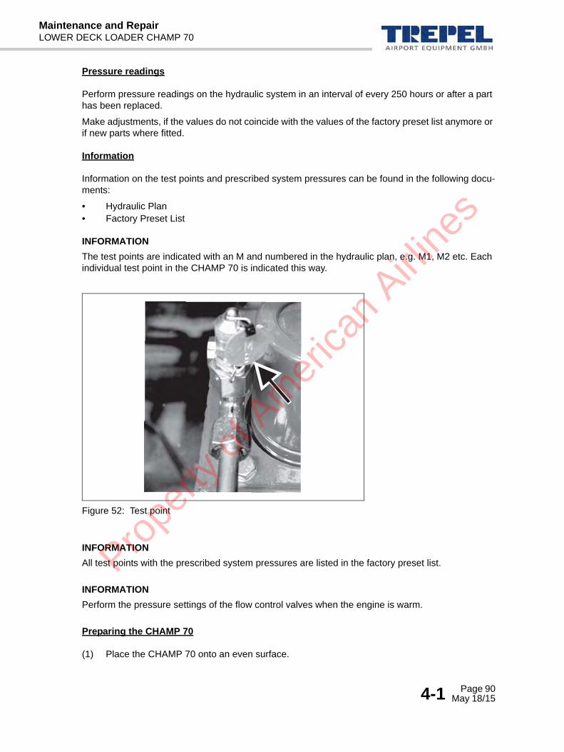
Maintenance and RepairLOWER DECK LOADER CHAMP 70
Pressure readings
Perform pressure readings on the hydraulic system in an interval of every 250 hours or after a part has been replaced.
Make adjustments, if the values do not coincide with the values of the factory preset list anymore or if new parts where fitted.
Information
Information on the test points and prescribed system pressures can be found in the following docu-ments:
• Hydraulic Plan• Factory Preset List
INFORMATION
The test points are indicated with an M and numbered in the hydraulic plan, e.g. M1, M2 etc. Each individual test point in the CHAMP 70 is indicated this way.
Figure 52: Test point
INFORMATION
All test points with the prescribed system pressures are listed in the factory preset list.
INFORMATION
Perform the pressure settings of the flow control valves when the engine is warm.
Preparing the CHAMP 70
(1) Place the CHAMP 70 onto an even surface.
Prope
rty o
f Am
erica
n Airli
nes
Page 904-1 May 18/15

Maintenance and Repair LOWER DECK LOADER CHAMP 70
Rolling CHAMP 70!
If the parking brake is not engaged, the CHAMP 70 can roll and run over service personnel.
A collision with the rolling CHAMP 70 can cause life threatening injuries and even death.
Ensure that the parking brake is engaged during maintenance work.
Ensure that blocks have been placed under the wheels.
(2) Engage parking brake.
(3) Place blocks under the wheels.
CHAMP 70 is secured from rolling away.
Lowering platform!
When working under the platform the service personnel can be crushed by lowering platforms.
The lowering platform can cause serious injuries or even death to the service personnel.
Never work under unsecured platforms.
Secure the raised platforms with maintenance blocks.
(4) Raise the bridge.
Danger of being crushed by platforms!
When securing the platform the service personnel can be crushed by lowering and raising the plat-form.
The lowering elevator can cause serious injuries or even death to the service personnel.
Always maintain visual and vocal contact to the operator on the driver's stand.
Only position maintenance blocks in the mounting position of the platforms once the operator has let go of the control switch for bridge up/down or the control switch for elevator up/down and the CHAMP 70 is stationary.
No service personnel may be present in the danger area of the CHAMP 70 during raising or lowering of the elevator.
(5) Place the maintenance blocks in the right and left position of the bridge.
The bridge is secured against unintended lowering.
(6) Elevator up.
(7) Place the maintenance blocks in the right and left position of the elevator.
The elevator is secured against unintended lowering.
(8) Turn off engine.
INFORMATION
Ideally, the pressure readings should be performed by two persons. One person performs the pres-sure readings. The second person supports the first person during the pressure readings, e.g. by switching the engine on and off at the switch cabinet or the engine compartment.
Prope
rty o
f Am
erica
n Airli
nes
Page 914-1 May 18/15

Maintenance and RepairLOWER DECK LOADER CHAMP 70
Performing pressure readings
Use the measuring tools consisting of a manometer, connection adapter, measuring hose and union nut for the pressure readings.
Ensure that the screw and hose connections of the measuring equipment are properly attached to the test point.
Select a manometer where the measuring range is 50 % higher than the measuring value of the test point.
Figure 53: Measuring equipment for pressure readings of the hydraulic system
1 Manometer up to 400/200/100 bar (5,800/2,900/1450 psi)
2 Union nut for connection to check point
3 Adapter
4 Measuring hose
2
3
4
1
Prope
rty o
f Am
erica
n Airli
nes
Page 924-1 May 18/15
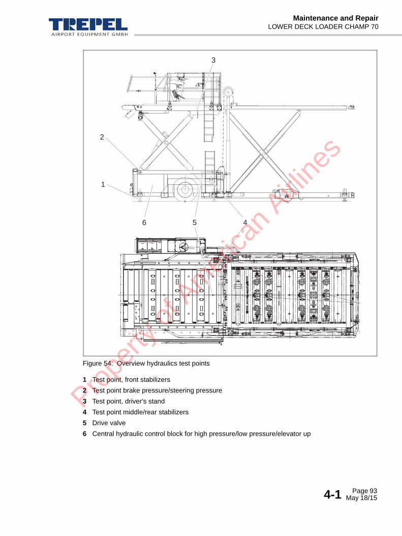
Maintenance and Repair LOWER DECK LOADER CHAMP 70
Figure 54: Overview hydraulics test points
1 Test point, front stabilizers
2 Test point brake pressure/steering pressure
3 Test point, driver's stand
4 Test point middle/rear stabilizers
5 Drive valve
6 Central hydraulic control block for high pressure/low pressure/elevator up
���
����
��������
�
1
5
3
2
46
Prope
rty o
f Am
erica
n Airli
nes
Page 934-1 May 18/15

Maintenance and RepairLOWER DECK LOADER CHAMP 70
Leaking hydraulic oil!
The hydraulic oil is under pressure. Suddenly emerging hydraulic oil can squirt into the eyes and injure other body parts.
Hydraulic oil emerging under pressure can seriously injure the service personnel.
Wear protective goggles when performing the pressure readings.
Harmful to the environment!
Leaking hydraulic oil pollutes the soil and the ground water.
Immediately catch leaking oil and dispose of in accordance with the laws and regulations.
(1) Select the test point.
(2) Read the system pressure from the factory preset list.
Figure 55: Measuring equipment attached to the CHAMP 70
1 Manometer
2 Test point
3 Union nut
2
3
1
Prope
rty o
f Am
erica
n Airli
nes
Page 944-1 May 18/15

Maintenance and Repair LOWER DECK LOADER CHAMP 70
Figure 56: Union nut attached to the test point
1 Union nut
(3) Unscrew the knurled nut from the test point, turn the knurled nut counter-clockwise for this.
(4) Screw the union nut of the measuring equipment onto the test point, turn the union nut clock-wise for this.
INFORMATION
Leave the engine on for the pressure readings.
(5) Switch the engine in the switch cabinet or engine room on.
(6) Operate the selected valve.
(7) Read the pressure on the manometer.
INFORMATION
If the measured values do not coincide with the values of the factory preset list, adjustments have to be made.
(8) Turn off engine.
INFORMATION
The adjustment screws for adjusting the pressure and the counternut for securing the pressure set-tings are under the protection cap.
1
Prope
rty o
f Am
erica
n Airli
nes
Page 954-1 May 18/15

Maintenance and RepairLOWER DECK LOADER CHAMP 70
Figure 57: Pressure settings
1 Set screw
2 Counternut
3 Protective cap
(9) Remove the orange protection cap.
(10) Unscrew lock nut.
(11) Set the correct pressure with the adjustment screw.
Turn the adjustment screw to the right = increase pressureTurn the adjustment screw to the left = decrease pressure
(12) Set the pressure settings with the counternut without turning the adjustment screw.
(13) Replace the orange protection cap.
2
3
1
Prope
rty o
f Am
erica
n Airli
nes
Page 964-1 May 18/15

Maintenance and Repair LOWER DECK LOADER CHAMP 70
High pressure settings – set value: 250 bar (3,650 psi)
Requirements
Before you begin the pressure readings and adjustments, the following conditions need to be met:
• Both platforms have to be secured against lowering with maintenance blocks.• No cargo is located on the platform.• Parking brake is engaged.• Wheels are blocked by blocks.• Motor is turned off.
Performing readings and settings
Figure 58: Test point M2 = high pressure
(1) Connect the measuring equipment to the rear of the main control block at test point M2.
(2) Switch the engine in the switch cabinet or engine room on.
Prope
rty o
f Am
erica
n Airli
nes
Page 974-1 May 18/15

Maintenance and RepairLOWER DECK LOADER CHAMP 70
Figure 59: Activate the valve for the high-pressure setting.
1 Valve Y5, not locked
2 Valve Y5, locked
(3) Operate valve Y5.
(4) Read the pressure on the manometer.
INFORMATION
If the measured values do not coincide with the values of the factory preset list, adjustments have to be made.
(5) Switch off the engine in the switch cabinet or engine room.
INFORMATION
Use the flat spanner with the following spanner widths for the pressure settings: Adjustment screw = spanner width 10 mm Counternut = spanner width 22 mm
(6) Remove the orange protection cap.
(7) Unscrew lock nut.
(8) Set the pressure to 250 bar (3,650 psi) with the adjustment screw.
1 2
Prope
rty o
f Am
erica
n Airli
nes
Page 984-1 May 18/15

Maintenance and Repair LOWER DECK LOADER CHAMP 70
Figure 60: High pressure setting on drive valve
INFORMATION
Once the pressure is set, perform the readings.
(9) Switch the engine in the switch cabinet or engine room on.
(10) Operate valve Y5.
(11) Read the pressure on the manometer.
INFORMATION
If the measured pressure coincides with the values of the factory preset list, the adjustments can be ended.
(12) Switch off the engine in the switch cabinet or engine room.
(13) Set the pressure settings with the counternut without turning the adjustment screw.
(14) Replace the orange protection cap.
(15) Remove the measuring equipment.
(16) Screw knurled nut onto the test point.
Prope
rty o
f Am
erica
n Airli
nes
Page 994-1 May 18/15

Maintenance and RepairLOWER DECK LOADER CHAMP 70
Low pressure setting – set value: 190 bar (2,800 psi)
Figure 61: Test point M1 = low pressure
Requirements
Before you begin the pressure readings and adjustments, the following conditions need to be met:
• Both platforms have to be secured against lowering with maintenance blocks.• No cargo is located on the platform.• Parking brake is engaged.• Wheels are blocked by blocks.• Motor is turned off.
Performing readings and settings
(1) Unscrew the knurled screw of the test point.
(2) Connect the measuring equipment to the rear of the main control block at test point M1.
(3) Switch the engine in the switch cabinet or engine room on.
Prope
rty o
f Am
erica
n Airli
nes
Page 1004-1 May 18/15

Maintenance and Repair LOWER DECK LOADER CHAMP 70
Figure 62: Operate the valve for low pressure settings
(4) Operate valve Y4.
(5) Read the pressure on the manometer and compare with the values of the factory preset list.
INFORMATION
If the measured values do not coincide with the values of the factory preset list, adjustments have to be made.
(6) Switch off the engine in the switch cabinet or engine room.
Prope
rty o
f Am
erica
n Airli
nes
Page 1014-1 May 18/15
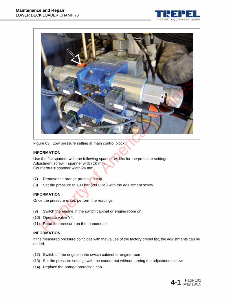
Maintenance and RepairLOWER DECK LOADER CHAMP 70
Figure 63: Low pressure setting at main control block
INFORMATION
Use the flat spanner with the following spanner widths for the pressure settings: Adjustment screw = spanner width 10 mm Counternut = spanner width 24 mm.
(7) Remove the orange protection cap.
(8) Set the pressure to 190 bar (2800 psi) with the adjustment screw.
INFORMATION
Once the pressure is set, perform the readings.
(9) Switch the engine in the switch cabinet or engine room on.
(10) Operate valve Y4.
(11) Read the pressure on the manometer.
INFORMATION
If the measured pressure coincides with the values of the factory preset list, the adjustments can be ended.
(12) Switch off the engine in the switch cabinet or engine room.
(13) Set the pressure settings with the counternut without turning the adjustment screw.
(14) Replace the orange protection cap.
Prope
rty o
f Am
erica
n Airli
nes
Page 1024-1 May 18/15
Maintenance and Repair LOWER DECK LOADER CHAMP 70
(15) Set the pressure settings with the counternut without turning the adjustment screw.
(16) Replace the orange protection cap.
(17) Switch off the engine in the switch cabinet or engine room.
(18) Remove the measuring equipment.
(19) Screw knurled nut onto the test point.
Prope
rty o
f Am
erica
n Airli
nes
Page 1034-1 May 18/15

Maintenance and RepairLOWER DECK LOADER CHAMP 70
Stabilizer pressure setting front stabilizers – set value 15-50 bar (220-730 psi)
There are two test points for setting the stabilizer pressure. There is a test point for the front stabi-lizers and a test point for the centre and rear stabilizers.
Requirements
Before you begin the pressure readings and adjustments, the following conditions need to be met:
• Both platforms have to be secured against lowering with maintenance blocks.• No cargo is located on the platform.• Parking brake is engaged.• Wheels are blocked by blocks.• Motor is turned off.
Performing readings and settings
Figure 64: Test point, front and rear stabilizers M9
(1) Unscrew the knurled screw of the test point.
(2) Connect measuring equipment to test point M9.
(3) The second person is standing in the driver's stand.
(4) Turn on engine from the driver's stand.
(5) Set "operate/drive mode selector" to operate mode.
The stabilizers extend.
"Stabilizers extended" control light is on.
(6) The first person is at the test point. They measure and set the pressure.
(7) Read the pressure on the manometer and compare with the values of the factory preset list.
Prope
rty o
f Am
erica
n Airli
nes
Page 1044-1 May 18/15

Maintenance and Repair LOWER DECK LOADER CHAMP 70
INFORMATION
If the measured values do not coincide with the values of the factory preset list, adjustments have to be made.
(8) The second person switches the engine off.
Figure 65: Pressure setting, front stabilizers
INFORMATION
Use the flat spanner with the following spanner widths for the pressure settings: Adjustment screw = spanner width 10 mm Counternut = spanner width 24 mm.
(9) Remove the orange protection cap.
(10) Unscrew lock nut.
(11) Set the pressure to 15-50 bar (220-730 psi) with the adjustment screw.
(12) The second person on the driver's stand switches the engine on.
(13) Set "operate/drive mode selector" to operate mode.
The stabilizers extend.
"Stabilizers extended" control light is on.
(14) The first person reads the pressure on the manometer.
INFORMATION
If the measured pressure coincides with the values of the factory preset list, the adjustments can be ended.
(15) The second person switches the engine off.
(16) The first person sets the pressure settings with the counternut without turning the adjustment screw.
Prope
rty o
f Am
erica
n Airli
nes
Page 1054-1 May 18/15

Maintenance and RepairLOWER DECK LOADER CHAMP 70
(17) Replace the orange protection cap.
(18) Remove the measuring equipment.
(19) Screw knurled nut onto the test point.
Prope
rty o
f Am
erica
n Airli
nes
Page 1064-1 May 18/15

Maintenance and Repair LOWER DECK LOADER CHAMP 70
Stabilizer pressure middle and rear stabilizers – set value: 15-50 bar (220-730 psi)
There are two test points for setting the stabilizer pressure. There is a test point for the front stabi-lizers and a test point for the centre and rear stabilizers.
Requirements
Before you begin the pressure readings and adjustments, the following conditions need to be met:
• Both platforms have to be secured against lowering with maintenance blocks.• No cargo is located on the platform.• Parking brake is engaged.• Wheels are blocked by blocks.• Motor is turned off.
Performing readings and settings
Figure 66: Test point, centre stabilizers M12
(1) Unscrew the knurled screw of the test point.
(2) Connect measuring equipment to test point.
(3) The second person is standing in the driver's stand.
(4) Turn on engine from the driver's stand.
"Stabilizers extended" control light is on.
Stabilizers are still extended.
(5) The first person is at the test point. They measure and set the pressure.
(6) Read the pressure on the manometer and compare with the values of the factory preset list.
Prope
rty o
f Am
erica
n Airli
nes
Page 1074-1 May 18/15

Maintenance and RepairLOWER DECK LOADER CHAMP 70
INFORMATION
If the measured values do not coincide with the values of the factory preset list, adjustments have to be made.
(7) The second person on the driver's stand switches the engine off.
Figure 67: Pressure setting, middle and rear stabilizers
INFORMATION
Use the flat spanner with the following spanner widths for the pressure settings: Adjustment screw = spanner width 10 mm Counternut = spanner width 24 mm.
(8) Remove the orange protection cap.
(9) Unscrew lock nut.
(10) Set the pressure to 15-50 bar (220-730 psi) with the adjustment screw.
INFORMATION
Once the pressure is set, perform the readings.
(11) The second person on the driver's stand switches the engine on.
(12) Set "operate/drive mode selector" to operate mode.
The stabilizers extend.
"Stabilizers extended "control light is on.
(13) The first person reads the pressure on the manometer.
Prope
rty o
f Am
erica
n Airli
nes
Page 1084-1 May 18/15

Maintenance and Repair LOWER DECK LOADER CHAMP 70
INFORMATION
If the measured pressure coincides with the values of the factory preset list, the adjustments can be ended.
(14) The second person switches the engine off.
(15) The first person sets the pressure settings with the counternut without turning the adjustment screw.
(16) Replace the orange protection cap.
(17) Remove the measuring equipment.
(18) Screw knurled nut onto the test point.
Prope
rty o
f Am
erica
n Airli
nes
Page 1094-1 May 18/15

Maintenance and RepairLOWER DECK LOADER CHAMP 70
Brake pressure settings for the operating brake – set value for hydraulic, dynamic braking: 60 bar (900 psi)
For the brake pressure setting, one person is in the driver's stand for the pressure setting and the second person is at the test points for pressure readings.
Requirements
Before you begin the pressure readings and adjustments, the following conditions need to be met:
• Both platforms are lowered.• No cargo is located on the platform.• Parking brake is engaged.• Wheels are blocked by blocks.• Motor is turned off.
Performing readings and settings
Figure 68: Test point, operating brake M7 and M8
(1) The first person connects the measuring equipment.
(2) Unscrew the knurled screw of the test point.
(3) Connect measuring equipment to test points M7 and M8.
(4) The second person is on the driver's stand, switches the motor on and sets the pressure at the adjustment screw below the brake pedal.
(5) Turn on engine from the driver's stand.
(6) Press the brake pedal all the way.
(7) The first person at the test point reads the pressure off the manometer and passes the meas-urement on to the second person.
Prope
rty o
f Am
erica
n Airli
nes
Page 1104-1 May 18/15
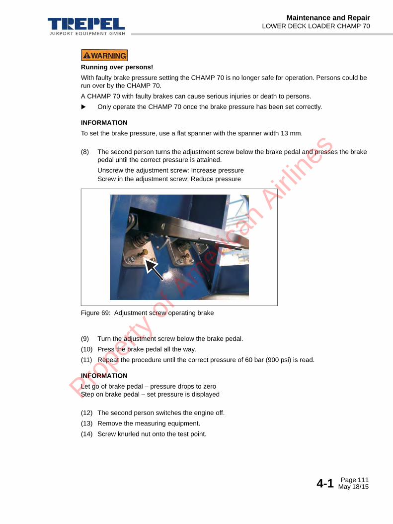
Maintenance and Repair LOWER DECK LOADER CHAMP 70
Running over persons!
With faulty brake pressure setting the CHAMP 70 is no longer safe for operation. Persons could be run over by the CHAMP 70.
A CHAMP 70 with faulty brakes can cause serious injuries or death to persons.
Only operate the CHAMP 70 once the brake pressure has been set correctly.
INFORMATION
To set the brake pressure, use a flat spanner with the spanner width 13 mm.
(8) The second person turns the adjustment screw below the brake pedal and presses the brake pedal until the correct pressure is attained.
Unscrew the adjustment screw: Increase pressureScrew in the adjustment screw: Reduce pressure
Figure 69: Adjustment screw operating brake
(9) Turn the adjustment screw below the brake pedal.
(10) Press the brake pedal all the way.
(11) Repeat the procedure until the correct pressure of 60 bar (900 psi) is read.
INFORMATION
Let go of brake pedal – pressure drops to zero Step on brake pedal – set pressure is displayed
(12) The second person switches the engine off.
(13) Remove the measuring equipment.
(14) Screw knurled nut onto the test point.
Prope
rty o
f Am
erica
n Airli
nes
Page 1114-1 May 18/15

Maintenance and RepairLOWER DECK LOADER CHAMP 70
Parking brake release pressure: at least 25 bar (365 psi)
The release pressure of the parking brake can only be checked. Adjustments are not possible.
Requirements
Before you begin the pressure readings, the following conditions need to be met:
• Both platforms are lowered.• No cargo is located on the platform.• Wheels are blocked by blocks.• Motor is turned off.
Performing readings
Figure 70: Test point, parking brake M10
(1) Unscrew the knurled screw of the test point.
(2) Connect measuring equipment to test point M10.
(3) Switch the engine in the switch cabinet or engine room on.
(4) Read the pressure on the manometer.
Property damage!
If the release pressure of the parking brake is below 25 bar (365 psi), the parking brake can be damaged.
Immediately shut down the CHAMP 70
Inform the TREPEL customer service.
Prope
rty o
f Am
erica
n Airli
nes
Page 1124-1 May 18/15

Maintenance and Repair LOWER DECK LOADER CHAMP 70
Running over persons!
With faulty brake pressure setting the CHAMP 70 is no longer safe for operation. Persons could be run over by the CHAMP 70.
A CHAMP 70 with faulty brakes can cause serious injuries or death to persons.
Only operate the CHAMP 70 once the brake pressure has been set correctly.
Prope
rty o
f Am
erica
n Airli
nes
Page 1134-1 May 18/15
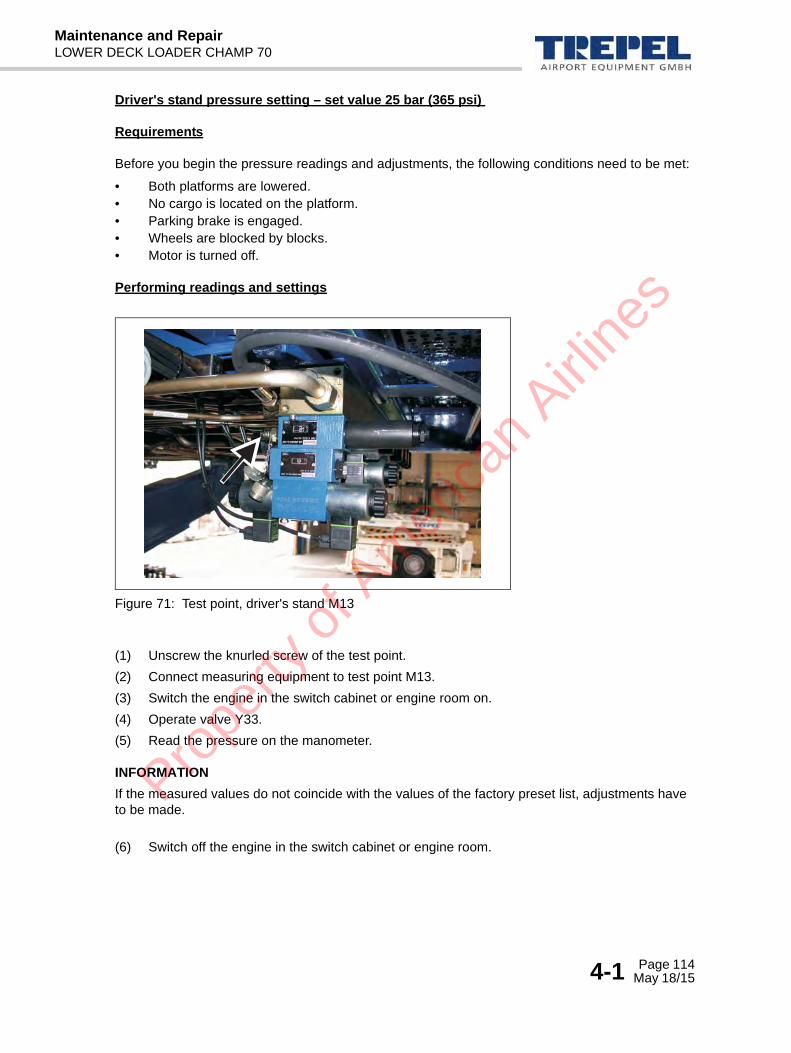
Maintenance and RepairLOWER DECK LOADER CHAMP 70
Driver's stand pressure setting – set value 25 bar (365 psi)
Requirements
Before you begin the pressure readings and adjustments, the following conditions need to be met:
• Both platforms are lowered.• No cargo is located on the platform.• Parking brake is engaged.• Wheels are blocked by blocks.• Motor is turned off.
Performing readings and settings
Figure 71: Test point, driver's stand M13
(1) Unscrew the knurled screw of the test point.
(2) Connect measuring equipment to test point M13.
(3) Switch the engine in the switch cabinet or engine room on.
(4) Operate valve Y33.
(5) Read the pressure on the manometer.
INFORMATION
If the measured values do not coincide with the values of the factory preset list, adjustments have to be made.
(6) Switch off the engine in the switch cabinet or engine room.
Prope
rty o
f Am
erica
n Airli
nes
Page 1144-1 May 18/15

Maintenance and Repair LOWER DECK LOADER CHAMP 70
Figure 72: Pressure settings driver's stand
INFORMATION
Use the flat spanner with the following spanner widths for the pressure settings: Adjustment screw = spanner width 10 mm Counternut = spanner width 24 mm.
(7) Remove the orange protection cap.
(8) Unscrew lock nut.
(9) Set the pressure to 25 bar (365 psi) with the adjustment screw.
INFORMATION
Once the pressure is set, perform the readings.
(10) Switch the engine in the switch cabinet or engine room on.
(11) Operate valve Y33.
(12) Read the pressure on the manometer.
INFORMATION
If the measured pressure coincides with the values of the factory preset list, the adjustments can be ended.
(13) Switch off the engine in the switch cabinet or engine room.
(14) Set the pressure settings with the counternut without turning the adjustment screw.
(15) Replace the orange protection cap.
(16) Remove the measuring equipment.
(17) Screw knurled nut onto the test point.
Prope
rty o
f Am
erica
n Airli
nes
Page 1154-1 May 18/15
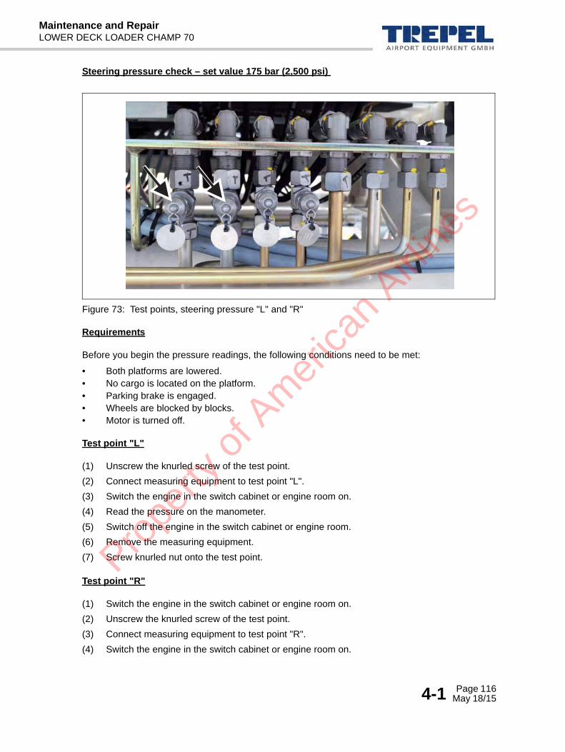
Maintenance and RepairLOWER DECK LOADER CHAMP 70
Steering pressure check – set value 175 bar (2,500 psi)
Figure 73: Test points, steering pressure "L" and "R"
Requirements
Before you begin the pressure readings, the following conditions need to be met:
• Both platforms are lowered.• No cargo is located on the platform.• Parking brake is engaged.• Wheels are blocked by blocks.• Motor is turned off.
Test point "L"
(1) Unscrew the knurled screw of the test point.
(2) Connect measuring equipment to test point "L".
(3) Switch the engine in the switch cabinet or engine room on.
(4) Read the pressure on the manometer.
(5) Switch off the engine in the switch cabinet or engine room.
(6) Remove the measuring equipment.
(7) Screw knurled nut onto the test point.
Test point "R"
(1) Switch the engine in the switch cabinet or engine room on.
(2) Unscrew the knurled screw of the test point.
(3) Connect measuring equipment to test point "R".
(4) Switch the engine in the switch cabinet or engine room on.
Prope
rty o
f Am
erica
n Airli
nes
Page 1164-1 May 18/15

Maintenance and Repair LOWER DECK LOADER CHAMP 70
(5) Read the pressure on the manometer.
(6) Switch off the engine in the switch cabinet or engine room.
(7) Remove the measuring equipment.
(8) Screw knurled nut onto the test point.
INFORMATION
If the steering pressure is lower than 175 bar (2,500 psi), the CHAMP 70 is hard to steer.
Property damage!
If the steering pressure is a lot higher than 175 bar (2500 psi), hydraulic cylinders can be damaged.
Shut down the CHAMP 70.
Inform the TREPEL customer service.
Prope
rty o
f Am
erica
n Airli
nes
Page 1174-1 May 18/15

Maintenance and RepairLOWER DECK LOADER CHAMP 70
Control pressure setting for speed regulator – set value 30 bar (450 psi)
Requirements
Before you begin the pressure readings, the following conditions need to be met:
• Both platforms are lowered.• No cargo is located on the platform.• Parking brake is engaged.• Wheels are blocked by blocks.• Motor is turned off.
Performing readings and settings
Figure 74: Test point, speed regulator M4 (in the front under the engine cover, right-hand side in travelling direction)
Property damage!
If the pressure is greater than 30 bar (450 psi), then the hydraulic servo cylinder mounted to the engine can become damaged.
Set no greater pressure than 30 bar (450 psi) for valve Y39.
(1) Unscrew the knurled screw of the test point.
(2) Connect measuring equipment to test point M4.
(3) Switch the engine in the switch cabinet or engine room on.
(4) Operate valve Y39.
(5) Read the pressure on the manometer.
Prope
rty o
f Am
erica
n Airli
nes
Page 1184-1 May 18/15

Maintenance and Repair LOWER DECK LOADER CHAMP 70
INFORMATION
If the measured values do not coincide with the values of the factory preset list, adjustments have to be made.
(6) Switch off the engine in the switch cabinet or engine room.
Figure 75: Pressure setting, speed regulator
INFORMATION
Use the flat spanner with the following spanner widths for the pressure settings: Adjustment screw = spanner width 10 mm Counternut = spanner width 24 mm.
(7) Remove the orange protection cap.
(8) Unscrew lock nut.
(9) Set the pressure to 30 bar (450 psi) with the adjustment screw.
INFORMATION
Once the pressure is set, perform the readings.
(10) Switch the engine in the switch cabinet or engine room on.
(11) Operate valve Y39.
(12) Read the pressure on the manometer.
INFORMATION
If the measured pressure coincides with the values of the factory preset list, the adjustments can be ended.
Prope
rty o
f Am
erica
n Airli
nes
Page 1194-1 May 18/15
Maintenance and RepairLOWER DECK LOADER CHAMP 70
(13) Switch off the engine in the switch cabinet or engine room.
(14) Set the pressure settings with the counternut without turning the adjustment screw.
(15) Replace the orange protection cap.
(16) Remove the measuring equipment.
(17) Screw knurled nut onto the test point.
Prope
rty o
f Am
erica
n Airli
nes
Page 1204-1 May 18/15

Maintenance and Repair LOWER DECK LOADER CHAMP 70
Electrical unit pressure setting nominal value 120 bar (1,750 psi)
Requirements
The following conditions have to be met before beginning with the pressure measurements:
• Both platforms are lowered• No cargo is located on the platforms• Parking brake is engaged• Stop blocks have been placed under the wheels• The engine is turned off
Conducting pressure measurements
Figure 76: Electrical unit test measurement point
1 Electrical unit
2 Setting screw with counter nut under black protective cap
3 Test measurement point M2 (high pressure) with system pressure manometer connected
(1) Unscrew knurled screw of the test measurement point M2.
(2) Connect system pressure manometer to the test measurement point M2.
(3) Switch on the engine at the switch cabinet or in the engine compartment.
(4) Press the "Lower elevator" button on the emergency operation switch cabinet and hold it down.
The elevator lowers.
(5) Read the pressure on the manometer.
1 2 3
Prope
rty o
f Am
erica
n Airli
nes
Page 1214-1 May 18/15

Maintenance and RepairLOWER DECK LOADER CHAMP 70
INFORMATION
In case the measured values do not match the values in the factory settings record, then re-adjust-ments need to be done.
(6) Release the "Lower elevator" button.
(7) Switch off the engine at the switch cabinet or in the engine compartment.
Adjusting the pressure settings
Use socket wrenches with the following sizes to adjust the pressure:
• Setting screw = wrench size 10 mm• Jam nut = wrench size 24 mm
(1) Pull off the black protective cap.
(2) Loosen the jam nut.
(3) Set the pressure with the setting screw to 120 bar (1,750 psi).
INFORMATION
Once the pressure has been set, conduct a measurement check.
(4) Switch on the engine at the switch cabinet or in the engine compartment.
(5) Press the "Lower elevator" button on the emergency operation switch cabinet and hold it down.
The elevator lowers.
(6) Read the pressure on the manometer.
INFORMATION
If the measured pressure matches the values in the factory settings record, the setting work can be ended.
(7) Release the "Lower elevator" button on the switch cabinet.
(8) Switch off the engine at the switch cabinet or in the engine compartment.
(9) Fix the pressure setting with the jam nut.
INFORMATION
Do not turn the setting screw when fixing the jam nut.
(10) Attach the black protective cap.
(11) Remove the measurement tool.
(12) Screw the knurled screw on to the test measurement point.
The measuring process has been completed.
Prope
rty o
f Am
erica
n Airli
nes
Page 1224-1 May 18/15
Maintenance and Repair LOWER DECK LOADER CHAMP 70
Flow regulator settings
Check the settings of the flow control valve in an interval of 250 operating hours. The settings are preset correctly ex factory and documented in the factory preset list. Nevertheless, some flow control valve settings can alter with usage of the CHAMP 70.
You can check and correct the speed and time of the following components with the flow control valves:
• Lead time for the extension and retraction of the adapters• Lead time for the extension and retraction of the guide rails
Information
Information on the measuring values can be found in the following documents:
• Hydraulic Plan• Factory Preset List
Preparing the CHAMP 70
(1) Place the CHAMP 70 onto an even surface.
Rolling CHAMP 70!
If the parking brake is not engaged, the CHAMP 70 can roll and run over service personnel.
A collision with the rolling CHAMP 70 can cause life threatening injuries and even death.
Ensure that the parking brake is engaged during maintenance work.
Ensure that blocks have been placed under the wheels.
(2) Engage parking brake.
(3) Place blocks under the wheels.
CHAMP 70 is secured from rolling away.
INFORMATION
The adjustments for the flow control valves are mostly performed under the platform.
Observe the following safety instructions:
Prope
rty o
f Am
erica
n Airli
nes
Page 1234-1 May 18/15
Maintenance and RepairLOWER DECK LOADER CHAMP 70
Danger of being crushed by platforms!
During the flow regulation settings the service personnel can be crushed by lowering and raising the platform.
The lowering elevator can cause serious injuries or even death to the service personnel.
Always maintain visual and vocal contact to the operator on the driver's stand.
Only perform settings on the flow control valves after the maintenance blocks have been placed.
Only position maintenance blocks in the mounting position of the platforms once the operator has let go of the control switch for bridge up/down or the control switch for elevator up/down and the CHAMP 70 is stationary.
No service personnel may be present in the danger area of the CHAMP 70 during raising or lowering of the elevator.
(4) Place the maintenance blocks in the right and left position of the bridge.
The bridge is secured against unintended lowering.
(5) Elevator up.
(6) Place the maintenance blocks in the right and left mounting positions of the elevator.
The elevator is secured against unintended lowering.
(7) Turn off engine.
Setting flow control valves
INFORMATION
To reduce the speed, turn the flow control valve towards the LARGE NUMBER.
To achieve a low flow speed, turn the flow control valve towards the SMALL NUMBER.
Change the setting of the flow control valve in small steps. Perform speed or time measurements after every change of setting.
Prope
rty o
f Am
erica
n Airli
nes
Page 1244-1 May 18/15

Maintenance and Repair LOWER DECK LOADER CHAMP 70
Flow control valves overview
Figure 77: Overview hydraulics flow control valves
1 Flow control valves left/right adapter MD B727 and speed of guide rails
Setting of the flow control valve for adapters
Figure 78: Flow control valves left/right adapter MD B727
1 Flow control valve left adapter
2 Flow control valve right adapter
1
12
Prope
rty o
f Am
erica
n Airli
nes
Page 1254-1 May 18/15
Maintenance and RepairLOWER DECK LOADER CHAMP 70
If the time duration for extending and retracting the adapters is supposed to be checked and set with the flow control valves, the actual time has to be measured first.
There is no existing lead time for the extension and retraction of the adapters in the factory preset list. The times can be adjusted according to the demand.
Requirements
• The CHAMP 70 is secured from rolling away, i.e.– parking brake is engaged – the blocks have been placed under the wheels
• Both platforms are secured against lowering with maintenance blocks.
Procedure
(1) The second person on the driver's stand switches the engine on.
(2) The second person operates the control switch for the respective adapter.
Adapter retracts or extends.
(3) Measure the time with a stop watch.
If the time does not correspond with the intended time, the flow control valve has to be set. (4) The second person switches the engine off.
INFORMATION
To reduce the speed, turn the flow control valve towards the LARGE NUMBER.
To achieve a low flow speed, turn the flow control valve towards the SMALL NUMBER.
Change the setting of the flow control valve in small steps. Perform speed or time measurements after every change of setting.
(5) Adjust flow control valve.
(6) Move out of the danger area of the CHAMP 70.
(7) The second person on the driver's stand switches the engine on.
(8) The second person operates the control switch for the respective adapter.
Adapter retracts or extends.
(9) Measure the time with a stop watch.
INFORMATION
If the measured time still does not correspond with the intended time, the process has to be repeated until there are no more deviations present.
If the measured time corresponds with the intended time, the setting process can be ended.
(10) The second person switches the engine off.
Prope
rty o
f Am
erica
n Airli
nes
Page 1264-1 May 18/15

Maintenance and Repair LOWER DECK LOADER CHAMP 70
Settings, flow control valve guide rail of bridge
Figure 79: Flow control valve guide rails of bridge
The flow control valve of the guide rails is positioned next to the flow control valve of the adapters.
If the extension and retraction speed of the guide rails is supposed to be checked and adjusted, the actual speed has to be measured first.
Requirements
• The CHAMP 70 is secured from rolling away, i.e.– parking brake is engaged – the blocks have been placed under the wheels
• Both platforms are secured against lowering with maintenance blocks.• No cargo is on the platforms.
Procedure
(1) The second person on the driver's stand switches the engine on.
(2) The second person operates the control switch guide rail bridge up/down.
Guide rails extend or retract.
(3) Measure the time with a stop watch.
INFORMATION
If the time does not correspond with the intended time, the flow control valve has to be set.
(4) The second person switches the engine off.
Prope
rty o
f Am
erica
n Airli
nes
Page 1274-1 May 18/15

Maintenance and RepairLOWER DECK LOADER CHAMP 70
INFORMATION
To reduce the speed, turn the flow control valve towards the LARGE NUMBER.
To achieve a low flow speed, turn the flow control valve towards the SMALL NUMBER.
Change the setting of the flow control valve in small steps. Perform speed or time measurements after every change of setting.
(5) Adjust flow control valve.
(6) Move out of the danger area of the CHAMP 70.
The service personnel is outside of the danger area.
(7) The second person on the driver's stand switches the engine on.
(8) The second person operates the control switch guide rail bridge up/down.
Guide rails extend or retract.
(9) Measure the time with a stop watch.
INFORMATION
If the measured time still does not correspond with the intended time, the process has to be repeated until there are no more deviations present.
If the measured time corresponds with the intended time, the setting process can be ended.
(10) The second person switches the engine off.
Prope
rty o
f Am
erica
n Airli
nes
Page 1284-1 May 18/15
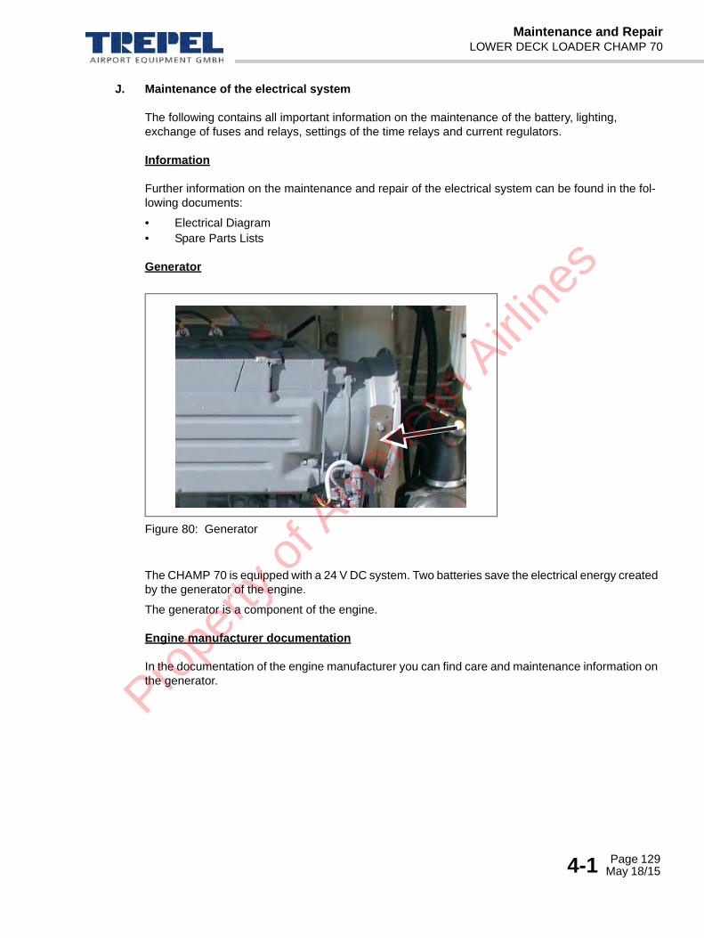
Maintenance and Repair LOWER DECK LOADER CHAMP 70
J. Maintenance of the electrical system
The following contains all important information on the maintenance of the battery, lighting, exchange of fuses and relays, settings of the time relays and current regulators.
Information
Further information on the maintenance and repair of the electrical system can be found in the fol-lowing documents:
• Electrical Diagram• Spare Parts Lists
Generator
Figure 80: Generator
The CHAMP 70 is equipped with a 24 V DC system. Two batteries save the electrical energy created by the generator of the engine.
The generator is a component of the engine.
Engine manufacturer documentation
In the documentation of the engine manufacturer you can find care and maintenance information on the generator.
Prope
rty o
f Am
erica
n Airli
nes
Page 1294-1 May 18/15

Maintenance and RepairLOWER DECK LOADER CHAMP 70
Main battery switch
Electric shock!
When working on the electrical system, electric shocks can occur.
Electric shocks can cause life threatening injuries or even death.
Only let qualified service personnel with extensive electrical knowledge perform maintenance and service work.
Switch off main battery switch and motor before work.
The main battery switch turns the power supply of the CHAMP 70 control system on/off.
Figure 81: Settings of the main battery switch
Table 11: Settings of the main battery switch
Switch positions Description
0 Voltage supply off.
I Voltage supply on.
Prope
rty o
f Am
erica
n Airli
nes
Page 1304-1 May 18/15
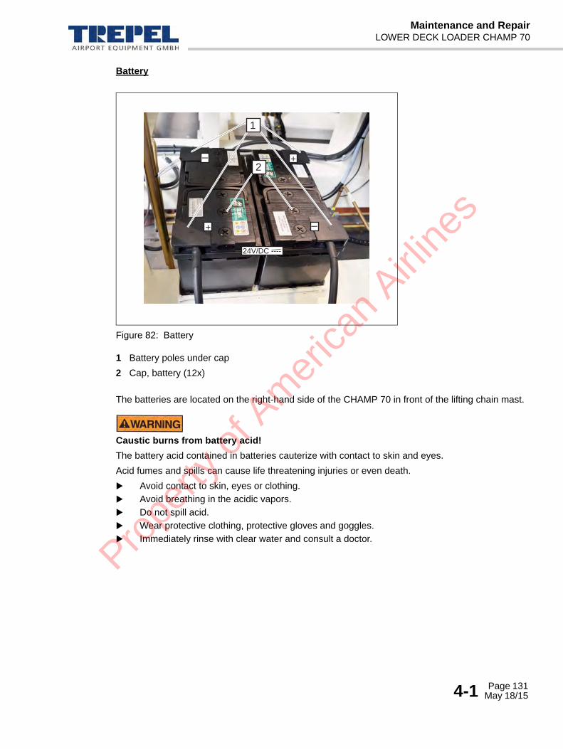
Maintenance and Repair LOWER DECK LOADER CHAMP 70
Battery
Figure 82: Battery
1 Battery poles under cap
2 Cap, battery (12x)
The batteries are located on the right-hand side of the CHAMP 70 in front of the lifting chain mast.
Caustic burns from battery acid!
The battery acid contained in batteries cauterize with contact to skin and eyes.
Acid fumes and spills can cause life threatening injuries or even death.
Avoid contact to skin, eyes or clothing.
Avoid breathing in the acidic vapors.
Do not spill acid.
Wear protective clothing, protective gloves and goggles.
Immediately rinse with clear water and consult a doctor.
+–
+ –
24V/DC ----
2
1
Prope
rty o
f Am
erica
n Airli
nes
Page 1314-1 May 18/15

Maintenance and RepairLOWER DECK LOADER CHAMP 70
Explosion danger!
Gases escaping from batteries are explosive.
Exploding battery vapors can lead to life threatening injuries or even death.
Avoid fire, open light, smoking and sparks near batteries.
Only charge batteries in well-ventilated rooms
Always wait a minimum of 30 minutes after the battery loading process before undertaking any welding work.
Do not place any tools on the battery.
Fire hazard!
Wrong sequence when connecting and disconnecting the battery terminals leads to short circuits.
Short circuits lead to fires and can cause life threatening injuries or even death.
Observe the correct sequence when connecting and disconnecting the battery terminals.
When disconnecting the battery, first remove the negative battery pole, then remove the posi-tive battery pole.
When connecting the battery, first connect the positive battery pole, then connect the nega-tive battery pole.
Check battery poles and connections
(1) Check battery terminals for corrosion.
(2) Check whether terminals are securely fastened.
(3) Check if the battery poles and terminals are sufficiently lubricated with acid free, acid resistant grease.
(4) Check whether the battery is securely fastened.
Check acid level
(1) Remove protective caps from the battery.
The acid level of the battery should be approx. 10 mm (0.4 inch) above the plate's top edge.(2) If the acid level is too low, carefully top up with distilled water.
(3) Replace the protective caps on the battery.
Checking battery status
The battery status can be determined by the acid concentration of the battery. The acid concentra-tion should be 1.28 g/cm³ (80 Pound per foot3). If the acid concentration is below 1.23 g/cm³ (77 Pound per foot3), the battery needs to be recharged.
INFORMATION
Use a battery acid spindle to determine the acid concentration.
Prope
rty o
f Am
erica
n Airli
nes
Page 1324-1 May 18/15

Maintenance and Repair LOWER DECK LOADER CHAMP 70
Charging the battery
(1) Check the battery acid level of the battery.
(2) Loosen and remove the battery terminals.
Observe the sequence - first loosen and remove the negative pole, then the positive pole.(3) Remove protective caps.
(4) Connect battery charging unit.
Observe the sequence - first connect the negative poles of the battery and battery charging unit, and then connect the positive poles.
(5) Switch on the battery charging unit.
(6) Remove the battery charging unit after the charging process.
Observe the sequence - first disconnect the positive poles of the battery and battery charging unit, and then disconnect the negative poles.
(7) Switch off the battery charging unit.
(8) Check battery status again.
INFORMATION
A lowered acid level can indicate a defective cell.
(9) Replace the protective caps on the battery.
(10) Replace defective battery.
INFORMATION
If the battery is functional, then connect the battery terminals and observe the sequence - first the positive pole, then the negative pole.
Engine manufacturer documentation
In the documentation of the engine manufacturer you can find care and maintenance information on the battery.
Prope
rty o
f Am
erica
n Airli
nes
Page 1334-1 May 18/15

Maintenance and RepairLOWER DECK LOADER CHAMP 70
Lighting system
Regularly check that the lighting system is operating faultlessly.
(1) Replace defective light bulbs.
(2) Check the diffusing reflector and light panel for chips and tears.
(3) Replace defective diffusing reflectors and light panels.
(4) Check the functionality of the reversing light with the reverse gear set.
Replacing the LED headlights and LED turn signals
INFORMATION
The headlights and the turn signals are cold-light LEDs. A defective headlight or turn signal has to be replaced completely.
Figure 83: LED headlights and LED turn signals
1 LED turn signals
2 LED headlights
2
1
Prope
rty o
f Am
erica
n Airli
nes
Page 1344-1 May 18/15
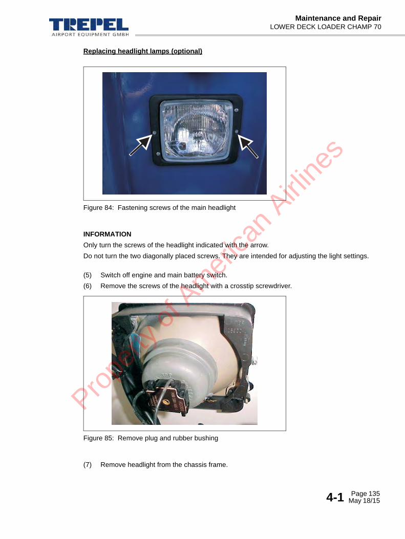
Maintenance and Repair LOWER DECK LOADER CHAMP 70
Replacing headlight lamps (optional)
Figure 84: Fastening screws of the main headlight
INFORMATION
Only turn the screws of the headlight indicated with the arrow.
Do not turn the two diagonally placed screws. They are intended for adjusting the light settings.
(5) Switch off engine and main battery switch.
(6) Remove the screws of the headlight with a crosstip screwdriver.
Figure 85: Remove plug and rubber bushing
(7) Remove headlight from the chassis frame.
Prope
rty o
f Am
erica
n Airli
nes
Page 1354-1 May 18/15

Maintenance and RepairLOWER DECK LOADER CHAMP 70
(8) Pull the plug on the back side of the headlight.
(9) Remove rubber bushing.
(10) Remove light bulb from the casing.
INFORMATION
Always replace light bulbs with light bulbs of the same model (type, voltage and power).
The individual types of light bulbs are listed in the spare parts list.
(11) Insert a new light bulb.
(12) Check the bushing for possible damages and replace if necessary.
(13) Replace the rubber bushing on the rear side of the headlight.
(14) Plug in the plug on the back side of the headlight.
(15) Reattach the headlight of the CHAMP 70 with screws.
(16) Switch on the main battery switch.
(17) Perform function test.
Exchanging light bulb, turn signal (optional)
Figure 86: Fastening screw for turn signal
(1) Switch off engine and main battery switch.
(2) Remove screws from the turn signal with crosstip screwdriver.
(3) Remove the Protective glass.
(4) Remove light bulb from the casing.
INFORMATION
Always replace light bulbs with light bulbs of the same model (type, voltage and power).
The individual types of light bulbs are listed in the spare parts list.
Prope
rty o
f Am
erica
n Airli
nes
Page 1364-1 May 18/15

Maintenance and Repair LOWER DECK LOADER CHAMP 70
(5) Insert a new light bulb.
(6) Check the seals for possible damages and replace if necessary.
(7) Replace the protective glass and screw tight.
(8) Switch on the main battery switch.
(9) Perform function test.
INFORMATION
If the light bulb does not light up after it has been changed, a relay or fuse might be defective. Check the electrical plan and the label "relay table" in the switch cabinet to locate the correspond-ing relay or fuse. Replace the relay or fuse.
If the light bulb does not light up or lights up only dimly, check that a light bulb with the correct volt-age or rating has been used.
Prope
rty o
f Am
erica
n Airli
nes
Page 1374-1 May 18/15

Maintenance and RepairLOWER DECK LOADER CHAMP 70
Replacing the LED headlights
INFORMATION
The headlights are cold-light LEDs. A defective headlight or turn signal has to be replaced com-pletely.
Figure 87: LED headlights
1 Protective grating
2 LED headlights
(1) Release the socket screws (4 used, see arrow) with a socket wrench.
(2) Remove the protective grating 1.
Figure 88: Replacing the rear light
1 Plug
2 Screws (2 pieces)
1 2
1 2
Prope
rty o
f Am
erica
n Airli
nes
Page 1384-1 May 18/15

Maintenance and Repair LOWER DECK LOADER CHAMP 70
(3) Pull the plug 1.
(4) Release the screws 2 (2 pieces).
(5) Remove the strip with the rear LED lights.
Replacing warning beacon light bulb
Figure 89: Mounting link for opening the warning beacon
(1) Switch off engine and main battery switch.
(2) To open the mounting link, press the warning beacon up.
(3) Remove the protective glass of the warning beacon.
INFORMATION
Do not touch the reflector with your bare hands while removing the light bulb.
(4) Remove light bulb from the casing.
INFORMATION
Always replace light bulbs with light bulbs of the same model (type, voltage and power).
The individual types of light bulbs are listed in the spare parts list.
(5) Insert a new light bulb.
(6) Check the seals for possible damages and replace if necessary.
INFORMATION
Make sure that the reflector is not soiled. If the reflector is dirty it has to be replaced.
(7) Replace the protective glass and snap the mounting link closed.
(8) Switch on the main battery switch.
(9) Perform function test.
Prope
rty o
f Am
erica
n Airli
nes
Page 1394-1 May 18/15

Maintenance and RepairLOWER DECK LOADER CHAMP 70
Working in the switch cabinet
The fuses, relays and current regulator are in the switch cabinet. This chapter describes the exchange of the fuses and relays, setting of the time lag relay and the current regulator.
Replacing fuses
(1) Switch off engine and main battery switch.
(2) Open the switch cabinet doors.
Figure 90: Fuses and relays
1 Relay
2 Current regulator
3 Fuses
Fire hazard!
Wrong fuses can lead to short circuits.
Short circuits lead to fires and can cause life threatening injuries or even death.
Only use fuses with the same ampere rating.
Never override blown fuses.
never exchange blown fuses with fuses with a higher voltage consumption.
(1) Check which fuse is defective with support from the electrical plan.
(2) Pull defective fuse from its holding device.
(3) Check the electrical contacts for secure attachment and corrosion.
(4) Insert a new fuse with the same amount of Ampere.
(5) Switch on the main battery switch.
2 3
1
Prope
rty o
f Am
erica
n Airli
nes
Page 1404-1 May 18/15

Maintenance and Repair LOWER DECK LOADER CHAMP 70
(6) Turn on engine, if necessary.
(7) Perform function test.
(8) Close switch cabinet door.
INFORMATION
Repeated blowing of replaced fuses is an indication that there is a defect within the electrical sys-tem.
Replacing relays
(1) Switch off engine and main battery switch.
(2) Open switch cabinet.
(3) Check which relay is defective with support from the electrical plan.
(4) Remove defective relay.
(5) Insert new relay.
(6) Check the electrical contacts for secure attachment and corrosion.
(7) Switch on the main battery switch.
(8) Perform function test.
(9) Close switch cabinet door.
Prope
rty o
f Am
erica
n Airli
nes
Page 1414-1 May 18/15
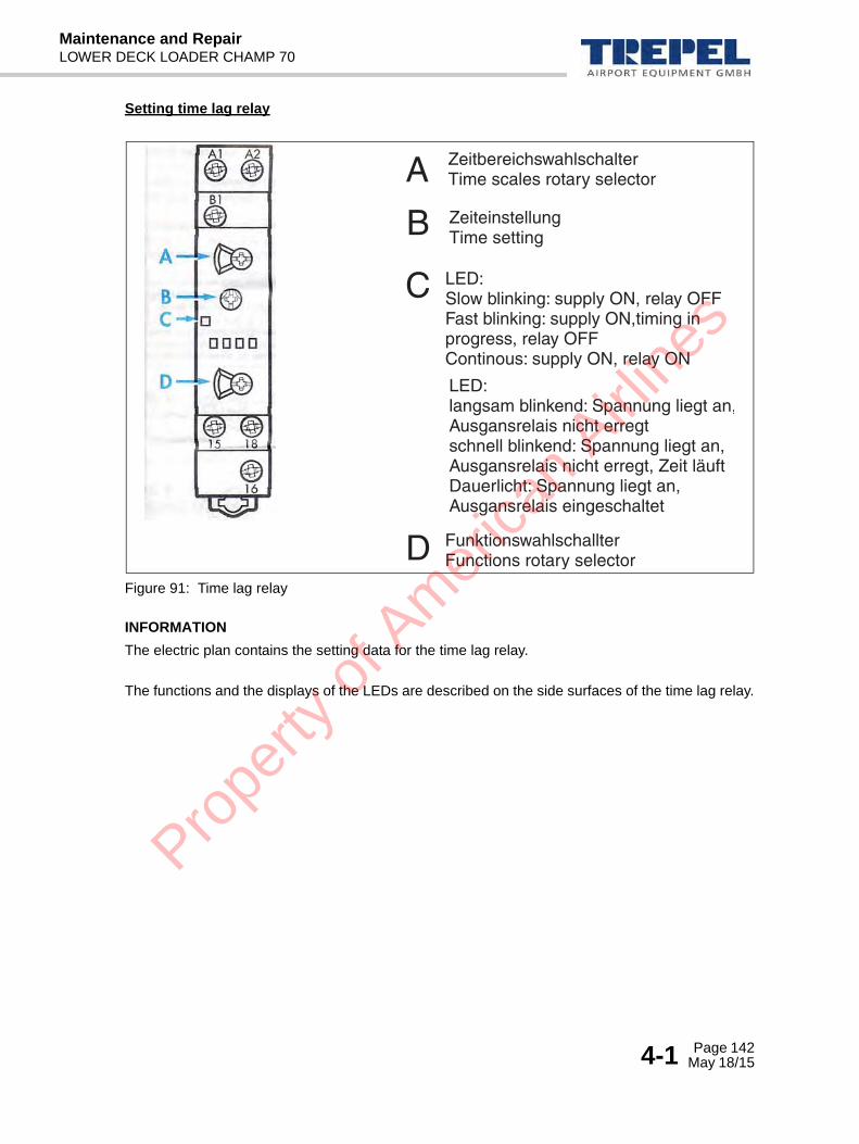
Maintenance and RepairLOWER DECK LOADER CHAMP 70
Setting time lag relay
Figure 91: Time lag relay
INFORMATION
The electric plan contains the setting data for the time lag relay.
The functions and the displays of the LEDs are described on the side surfaces of the time lag relay.
Prope
rty o
f Am
erica
n Airli
nes
Page 1424-1 May 18/15

Maintenance and Repair LOWER DECK LOADER CHAMP 70
Settings at the time lag relay
The time lag relay should, for instance, be set to a response delay of 30 seconds.
Proceed as follows:
(1) Set the function switch to AI ( = response delay – On delay).
(2) Set time switch to "1 min" (1 minute).
(3) Set the multiplier switch for time domain to "5".
(4) If you multiply 1 minute (60 seconds) with 0.5 you receive the result ½ minute or 30 seconds.
The time lag relay is set to 30 seconds.
INFORMATION
If, for instance, the multiplier is set to 10, there is no response delay.
Prope
rty o
f Am
erica
n Airli
nes
Page 1434-1 May 18/15

Maintenance and RepairLOWER DECK LOADER CHAMP 70
Setting current regulator
The current regulator adjusts the opening width of the hydraulic valve magnet. This determines the amount and speed of the hydraulic oil throughput.
The throughput amount is set with the maximum current adjustment screw "I max".
Figure 92: Electrical current regulator
1 LED indicator
2 Maximum current
Increasing throughput amount
(1) Turn the adjustment screw "I max" clockwise with a flat headed screw driver.
Reducing throughput amount
(1) Turn the setting screw "I max" counter-clockwise with a flat headed screw driver.
INFORMATION
All other settings of the current regulator are preset from the factory and may not be changed to avoid errors and malfunctions.
The settings may only be changed by the TREPEL service personnel.
2
1
Prope
rty o
f Am
erica
n Airli
nes
Page 1444-1 May 18/15

Maintenance and Repair LOWER DECK LOADER CHAMP 70
Proximity switch
This chapter describes the exchange of the proximity switch and the setting of the switch distance.
The CHAMP 70 is equipped with electrical proximity switches. The electrical proximity switches work non-contact, i.e. the switching plate is recognized with a sensor and a signal is created. The signal triggers the switch of the proximity switch.
Requirements
Before you begin to exchange proximity switches or to set the switch distance, the following condi-tions need to be met:
• No cargo is located on the platform.• Parking brake is engaged.• Wheels are blocked by blocks.• Motor is turned off.• The main battery switch is switched off.
Working under raised platforms
While replacing or adjusting the proximity switch you partially work under the platforms.
Observe the following safety instructions for this:
Lowering platform!
When working under the platform the service personnel can be crushed by lowering platforms.
The lowering platform can cause serious injuries or even death to the service personnel.
Never work under unsecured platforms.
Secure the raised platforms with maintenance blocks.
Prope
rty o
f Am
erica
n Airli
nes
Page 1454-1 May 18/15
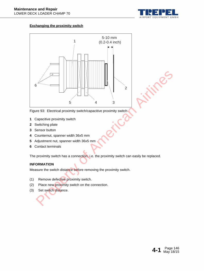
Maintenance and RepairLOWER DECK LOADER CHAMP 70
Exchanging the proximity switch
Figure 93: Electrical proximity switch/capacitive proximity switch
1 Capacitive proximity switch
2 Switching plate
3 Sensor button
4 Counternut, spanner width 36x5 mm
5 Adjustment nut, spanner width 36x5 mm
6 Contact terminals
The proximity switch has a connection, i.e. the proximity switch can easily be replaced.
INFORMATION
Measure the switch distance before removing the proximity switch.
(1) Remove defective proximity switch.
(2) Place new proximity switch on the connection.
(3) Set switch distance.
5-10 mm (0.2-0.4 inch)1
5
2
34
6
Prope
rty o
f Am
erica
n Airli
nes
Page 1464-1 May 18/15

Maintenance and Repair LOWER DECK LOADER CHAMP 70
Set switch distance
The distance between the switching plate and the sensor surface can be changed with the setting nut. The setting of the switching distance is fixed with the locking nut.
INFORMATION
If the proximity switch reacts to the switching plate, then the switching distance is set correctly.
The optimum switching distance between the sensor surface and the switching plate is 5-10 mm (0.2-0.4 inch).
(1) Unscrew lock nut.
(2) Turn the setting nut with the screw wrench and set the desired switch distance.
(3) Carry out a functional test.
Prope
rty o
f Am
erica
n Airli
nes
Page 1474-1 May 18/15

Maintenance and RepairLOWER DECK LOADER CHAMP 70
This page intentionally left blank.
Prope
rty o
f Am
erica
n Airli
nes
Page 148(Blank) May 18/154-1

Maintenance and Repair LOWER DECK LOADER CHAMP 70
4. Operational Materials
This chapter informs you about operational materials that are used for operating the CHAMP 70.
Operational materials are fuels and lubricants, such as engine oils, gear oils, greases, and coolants.
Observe the valid regulations, ordinances, and standards of the country of operation.
Operational material regulations
Be sure to observe the operational material specifications of the manufacturer of the engine, transmission, and axle manufacturers.
Vehicle identification sheet
In the CHAMP 70's vehicle identification sheet, you will find filling amounts and specifications of the oper-ational materials that are factory-filled in the CHAMP 70.
A. Safety Information
Danger of poisoning!
Operational materials can contain toxic ingredients.
Touching, swallowing, or inhaling operational materials can lead to poisoning.
When handling operational materials, wear suitable protective clothing and breathing protec-tion.
Do not spill operational materials.
In case of skin contact with operational materials, thoroughly rinse the affected areas of the skin.
In case of eye contact with operational materials, rinse out eyes for 10 to 15 minutes with clear water and consult a doctor.
If operational materials are swallowed, consult a doctor immediately.
Fire hazard!
Operational materials are highly flammable and can lead to fires.
Persons can be seriously injured or even killed because of fires.
When handling operational materials, do not use naked flames, lighting, or tools that generate sparks.
Smoking is prohibited during all service work on the CHAMP 70.
Operational materials are an environmental hazard!
Spilled operational materials contaminate the soil and the groundwater.
Exchange operational materials only in places designated for this task.
Dispose of used oils according to the valid national laws and regulations.
If in doubt, contact your shop or certified disposal company.
Prope
rty o
f Am
erica
n Airli
nes
Page 1494-1 May 18/15
Maintenance and RepairLOWER DECK LOADER CHAMP 70
Impermissible fuels!
Using impermissible fuels can damage the fuel system and/or the engine of the CHAMP 70.
Only use fuels that are compliant with the specified standards and the amended national envi-ronmental and low-temperature requirements.
Do not use kerosene, heating oils, or marine diesel fuels.
Do not add normal or premium gasoline to the diesel fuel.
Engine damage!
Sustained use of petroleum mixed with the fuel can lead to engine damage.
Adapt the amount of petroleum added to the engine temperature and keep the amount as low as possible.
Observe the information on the mixing ratio provided in the documentation of the engine man-ufacturer.
Impermissible coolant!
Using impermissible fuel can negatively affect the corrosion protection and damage the engine of the CHAMP 70.
Only use coolants authorized by the engine manufacturer.
Prope
rty o
f Am
erica
n Airli
nes
Page 1504-1 May 18/15

Maintenance and Repair LOWER DECK LOADER CHAMP 70
B. Fuels
Cleanliness when refueling
When refueling and when working on the fuel system, cleanliness is important. Dirt or water in the fuel system can damage the fuel pump and the injection system.
Fuel specifications
Only refuel using commercially available diesel fuel with a sulfur content of less than 0.5 %.
INFORMATION
If the diesel fuel has a high sulfur content, operational safety and the long-term durability of the exhaust after-treatment system cannot be guaranteed.
Only use fuels that are compliant with the following standards and the amended national environ-mental and low-temperature requirements:
• EN 590• ASTM D 975 1-D• ASTM D 975 2-D
Impermissible fuels!
Use of fuels that are not permitted can damage the fuel system, the engine and/or the exhaust after-treatment system of the CHAMP 70.
Only use fuels that are compliant with the specified standards and the amended national envi-ronmental and low-temperature requirements.
Do not use kerosene, heating oils, or marine diesel fuels.
INFORMATION
Fuels that do not comply with the standards above require the permission of the manufacturer. Using non-approved fuels voids the warranty.
If you plan to use biodiesel, first consult the engine manufacturer whether the engine of your CHAMP 70 is suitable for operation with biodiesel.
Prope
rty o
f Am
erica
n Airli
nes
Page 1514-1 May 18/15

Maintenance and RepairLOWER DECK LOADER CHAMP 70
Operation with diesel fuel during winter
Operation during winter places special demands on low-temperature performance (cold filter plug-ging point). The appropriate fuels are available at gas stations in winter.
For engines with common rail injection, admixtures of petroleum and the addition of extra fluid additives is not permitted.
To avoid malfunctions and clogging in the fuel system, winter diesel fuel has to be used if the ambient temperature is below 0 °C (32°F).
The winter diesel fuel can be used for temperatures down to –20 °C (–4 °F) and is available at fuel stations well in time before the start of the cold months of the year. In the transition period and in individual countries, this might not always be the case.
Impermissible fuel!
Adding normal or premium gasoline can heavily damage the engine.
Do not add normal or premium gasoline to the diesel fuel.
INFORMATION
For arctic regions, special diesel fuels suitable for temperatures down to –44 °C (–47 °F) can be used. See also http://www.deutz.com/service/operating_liquids_brand_additives/fuels.en.html.
Prope
rty o
f Am
erica
n Airli
nes
Page 1524-1 May 18/15
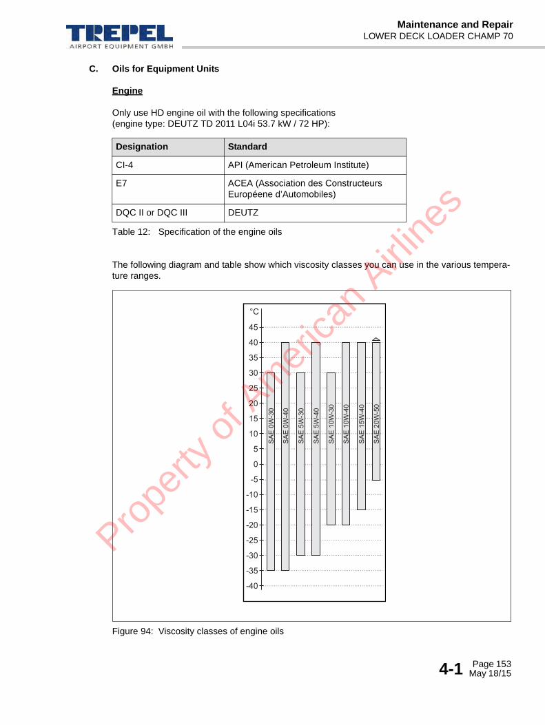
Maintenance and Repair LOWER DECK LOADER CHAMP 70
C. Oils for Equipment Units
Engine
Only use HD engine oil with the following specifications (engine type: DEUTZ TD 2011 L04i 53.7 kW / 72 HP):
Table 12: Specification of the engine oils
The following diagram and table show which viscosity classes you can use in the various tempera-ture ranges.
Figure 94: Viscosity classes of engine oils
Designation Standard
CI-4 API (American Petroleum Institute)
E7 ACEA (Association des Constructeurs Européene d’Automobiles)
DQC II or DQC III DEUTZ
Prope
rty o
f Am
erica
n Airli
nes
Page 1534-1 May 18/15
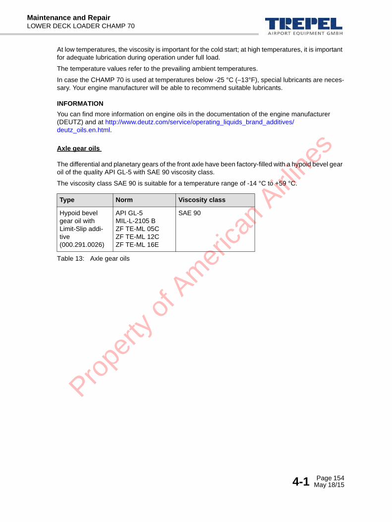
Maintenance and RepairLOWER DECK LOADER CHAMP 70
At low temperatures, the viscosity is important for the cold start; at high temperatures, it is important for adequate lubrication during operation under full load.
The temperature values refer to the prevailing ambient temperatures.
In case the CHAMP 70 is used at temperatures below -25 °C (–13°F), special lubricants are neces-sary. Your engine manufacturer will be able to recommend suitable lubricants.
INFORMATION
You can find more information on engine oils in the documentation of the engine manufacturer (DEUTZ) and at http://www.deutz.com/service/operating_liquids_brand_additives/deutz_oils.en.html.
Axle gear oils
The differential and planetary gears of the front axle have been factory-filled with a hypoid bevel gear oil of the quality API GL-5 with SAE 90 viscosity class.
The viscosity class SAE 90 is suitable for a temperature range of -14 °C to +59 °C.
Table 13: Axle gear oils
Type Norm Viscosity class
Hypoid bevel gear oil with Limit-Slip addi-tive (000.291.0026)
API GL-5 MIL-L-2105 B ZF TE-ML 05C ZF TE-ML 12C ZF TE-ML 16E
SAE 90
Prope
rty o
f Am
erica
n Airli
nes
Page 1544-1 May 18/15

Maintenance and Repair LOWER DECK LOADER CHAMP 70
Hydraulic oils
Use a hydraulic oil of the specification HLP-ISO-VG for the hydraulic system.
The following diagram shows which viscosity classes you can use in the temperature ranges of out-side air.
Figure 95: Viscosity classes of hydraulic oil
The temperature values refer to the prevailing ambient temperatures.
- 40- 30- 20- 10
+ 10+ 20+ 30+ 40+ 50
- 40- 22- 4
+ 32- 14
+ 50+ 68+ 86+ 104+ 122
11-C00-021-002A-2
Prope
rty o
f Am
erica
n Airli
nes
Page 1554-1 May 18/15

Maintenance and RepairLOWER DECK LOADER CHAMP 70
D. Lubricating Greases
The lubricating greases should reduce friction and wear, prevent corrosion, seal lubricating points, and be resistant to occurring operating temperatures.
Consider the operating circumstances, outside influences, lubrication intervals, and especially the performance characteristics of the grease when selecting a suitable lubrication grease.
Table 14: Lubricating greases
Type Standard Viscosity class
Exterior temperature
Chain spray commercially available
– Drop point <170 °C (<338 °F)
Lithium based multi-purpose grease
DIN 51502 – Drop point <170 °C (<338 °F)
Acid-resistant grease for battery terminals
e.g. BOSCH 5700 102025
– –
Prope
rty o
f Am
erica
n Airli
nes
Page 1564-1 May 18/15

Maintenance and Repair LOWER DECK LOADER CHAMP 70
Section 2Troubleshooting
1. Troubleshooting
The following provides support for searching for the cause of a malfunction on the CHAMP 70.
Before you start with the troubleshooting, make sure that there were no operator errors or no mechanical damage is present or that lubricants and fuels are lacking.
A. Tasks before troubleshooting
Electrical system
Check the following items before troubleshooting in the electrical system:
• Fixing of screw and weld connections• Function of the control lights and LCDs• working fuses• correct function of battery, generator and their regulators• cabling follows the original circuit diagram• all EMERGENCY OFF buttons unlocked
Have the electrical diagram ready at hand.
Hydraulic system
Check the following items before troubleshooting in the hydraulic system:
• Setpoint setting of all pressure valves • full hydraulic tank• Function of the solenoid valves• Setpoint setting of the flow control valves• Leaks
Have the hydraulic diagram ready at hand.
Prope
rty o
f Am
erica
n Airli
nes
Page 14-2 May 18/15

Maintenance and RepairLOWER DECK LOADER CHAMP 70
B. Troubleshooting Table
Malfunction Possible cause
Remedy
Engine does not start Main battery switch not turned on.
Turn on main battery switch "-S0".
Operate/drive mode selector is not in middle position
Check position of control switch "-S42".
Emergency-off chain active. Emergency off LED is lit
• Check all emergency off buttons.• Check hydraulic oil level "-H21".• Check if shut-off cock hydraulic tank
"-H78" is locked.• Check engine oil pressure "-H8".• Check engine temperature "-H10".• Check fuel level "-P2".• Check emergency stop limit switch for
lift system "-S41".
After changing the fuel filter
• Vent the fuel system by using a hand pump.
• Activate starter for 2 minutes.
The engine does not automatically run at operating speed
Engine components defective
Ask the engine manufacturer.
Prope
rty o
f Am
erica
n Airli
nes
Page 24-2 May 18/15
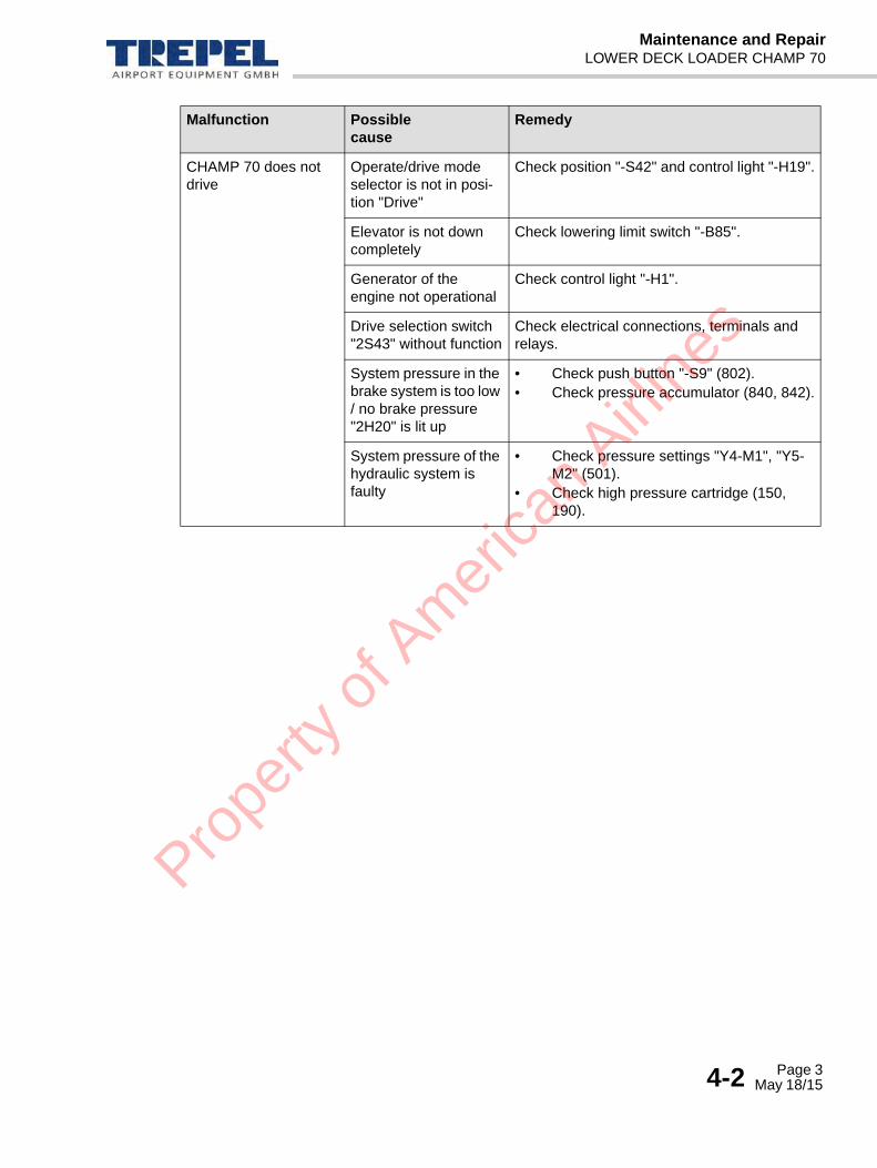
Maintenance and Repair LOWER DECK LOADER CHAMP 70
CHAMP 70 does not drive
Operate/drive mode selector is not in posi-tion "Drive"
Check position "-S42" and control light "-H19".
Elevator is not down completely
Check lowering limit switch "-B85".
Generator of the engine not operational
Check control light "-H1".
Drive selection switch "2S43" without function
Check electrical connections, terminals and relays.
System pressure in the brake system is too low / no brake pressure "2H20" is lit up
• Check push button "-S9" (802).• Check pressure accumulator (840, 842).
System pressure of the hydraulic system is faulty
• Check pressure settings "Y4-M1", "Y5-M2" (501).
• Check high pressure cartridge (150, 190).
Malfunction Possible cause
Remedy
Prope
rty o
f Am
erica
n Airli
nes
Page 34-2 May 18/15
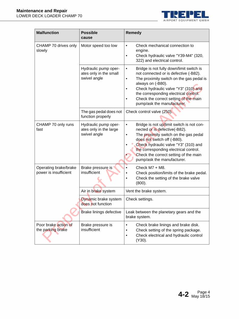
Maintenance and RepairLOWER DECK LOADER CHAMP 70
CHAMP 70 drives only slowly
Motor speed too low • Check mechanical connection to engine.
• Check hydraulic valve "Y39-M4" (320, 322) and electrical control.
Hydraulic pump oper-ates only in the small swivel angle
• Bridge is not fully down/limit switch is not connected or is defective (-B82).
• The proximity switch on the gas pedal is always on (-B80).
• Check hydraulic valve "Y3" (310) and the corresponding electrical control.
• Check the correct setting of the main pump/ask the manufacturer.
The gas pedal does not function properly
Check control valve (250).
CHAMP 70 only runs fast
Hydraulic pump oper-ates only in the large swivel angle
• Bridge is not up/limit switch is not con-nected or is defective(-B82).
• The proximity switch on the gas pedal does not switch off (-B80).
• Check hydraulic valve "Y3" (310) and the corresponding electrical control.
• Check the correct setting of the main pump/ask the manufacturer.
Operating brake/brake power is insufficient
Brake pressure is insufficient
• Check M7 + M8. • Check position/limits of the brake pedal.• Check the setting of the brake valve
(800).
Air in brake system Vent the brake system.
Dynamic brake system does not function
Check settings.
Brake linings defective Leak between the planetary gears and the brake system.
Poor brake action of the parking brake
Brake pressure is insufficient
• Check brake linings and brake disk.• Check setting of the spring package.• Check electrical and hydraulic control
(Y30).
Malfunction Possible cause
Remedy
Prope
rty o
f Am
erica
n Airli
nes
Page 44-2 May 18/15

Maintenance and Repair LOWER DECK LOADER CHAMP 70
Stabilizers do not retract or retract insuffi-ciently
elevator is not lowered completely Limit switch not used or defective
Check lowering limit switch "-B85".
Control switch "-S42" does not function prop-erly
Check electrical connections, terminals and relays.
Time lag relay does not function properly or is incorrectly set
Check relay "-K10".
System pressure is insufficient
• Check hydraulic valve "Y4-M1" (501).• Check hydraulic valve "Y16" (204).• Check high pressure cartridge (150/
190).• Check hydraulic valve "Y7-M9", "M12".
Low outside tempera-ture
Warm up CHAMP 70 to operating tempera-ture.
Stabilizers do not extend or extend insuf-ficiently
Parking brake is not engaged
• Check control switch "-S43". • Check control light "-H13".
Control switch "-S42" does not function prop-erly
Check electrical connections, terminals and relays.
Time lag relay does not function properly or is incorrectly set
Check relay "-K9".
System pressure is insufficient
• Check hydraulic valve "Y4-M1" (501).• Check hydraulic valve "Y16" (204).• Check high pressure cartridge (150/
190).• Check hydraulic valve "Y8" (520).
Low outside tempera-ture
Warm up CHAMP 70 to operating tempera-ture.
Malfunction Possible cause
Remedy
Prope
rty o
f Am
erica
n Airli
nes
Page 54-2 May 18/15

Maintenance and RepairLOWER DECK LOADER CHAMP 70
The bridge does not lift. Control switch "-S44"/ "-S44.1" does not func-tion properly
Check electrical connections, terminals and relays.
System pressure is insufficient
• Check hydraulic valve "Y5-M2" (501).• Check hydraulic valve "Y16" (204).• Check high pressure cartridge (150/
190).• Check hydraulic valve "Y11" (540).• Check flow regulator (373).
Lifting limit switch in use or defective
Check limit switch "-B81".
The bridge does not lower
Control switch "-S44"/ "-S44.1" does not func-tion properly
Electrical connections, terminals and relays
Control pressure is insufficient
• Check hydraulic valve "Y4-M1" (501).• Check hydraulic valve "Y16" (204).• Check high pressure cartridge (150/
190).• Check hydraulic valve "Y12" (540).• Check flow regulator (373).
Malfunction Possible cause
Remedy
Prope
rty o
f Am
erica
n Airli
nes
Page 64-2 May 18/15
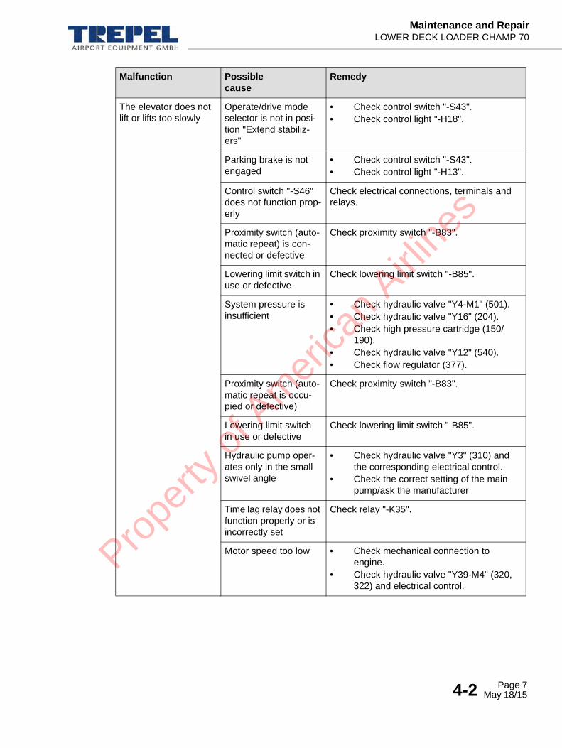
Maintenance and Repair LOWER DECK LOADER CHAMP 70
The elevator does not lift or lifts too slowly
Operate/drive mode selector is not in posi-tion "Extend stabiliz-ers"
• Check control switch "-S43".• Check control light "-H18".
Parking brake is not engaged
• Check control switch "-S43". • Check control light "-H13".
Control switch "-S46" does not function prop-erly
Check electrical connections, terminals and relays.
Proximity switch (auto-matic repeat) is con-nected or defective
Check proximity switch "-B83".
Lowering limit switch in use or defective
Check lowering limit switch "-B85".
System pressure is insufficient
• Check hydraulic valve "Y4-M1" (501).• Check hydraulic valve "Y16" (204).• Check high pressure cartridge (150/
190). • Check hydraulic valve "Y12" (540).• Check flow regulator (377).
Proximity switch (auto-matic repeat is occu-pied or defective)
Check proximity switch "-B83".
Lowering limit switch in use or defective
Check lowering limit switch "-B85".
Hydraulic pump oper-ates only in the small swivel angle
• Check hydraulic valve "Y3" (310) and the corresponding electrical control.
• Check the correct setting of the main pump/ask the manufacturer
Time lag relay does not function properly or is incorrectly set
Check relay "-K35".
Motor speed too low • Check mechanical connection to engine.
• Check hydraulic valve "Y39-M4" (320, 322) and electrical control.
Malfunction Possible cause
Remedy
Prope
rty o
f Am
erica
n Airli
nes
Page 74-2 May 18/15

Maintenance and RepairLOWER DECK LOADER CHAMP 70
Elevator does not lower or lowers too slowly
Operate/drive mode selector is not in posi-tion "Extend stabiliz-ers"
• Check control switch "-S42".• Check control light "-H18".
Parking brake is not engaged
• Check control switch "-S43".• Check control light "-H13".
Control switch "-S46" does not function prop-erly
Check electrical connections, terminals and relays.
Control pressure is insufficient
• Check hydraulic valve "Y4" (M1).• Check hydraulic valve "Y16" (204).• Check high pressure cartridge (150/
1190). • Check hydraulic valve "Y9" (521).• Check flow regulator (522).
PC drives are not work-ing or some sections are not working
Operate/drive mode selector is not in posi-tion "Extend stabiliz-ers"
• Check control switch "-S42".• Check control light "-H18".
Parking brake is not engaged
• Check control switch "-S43".• Check control light "-H13" .
System pressure is insufficient
• Check PC drives of the emergency operating equipment.
• Check hydraulic valve "Y4" (M1).• Check high pressure cartridge (150/
190). • Carry out troubleshooting procedure
using the hydraulic diagram.
Current regulator defective set improp-erly
• Check regulators -A34 to -A37.• Check regulators -A50 to -A55.
Control switch "-S47", "-S49", "-S50" does not function properly
Check electrical connections, terminals and relays.
Malfunction Possible cause
Remedy
Prope
rty o
f Am
erica
n Airli
nes
Page 84-2 May 18/15
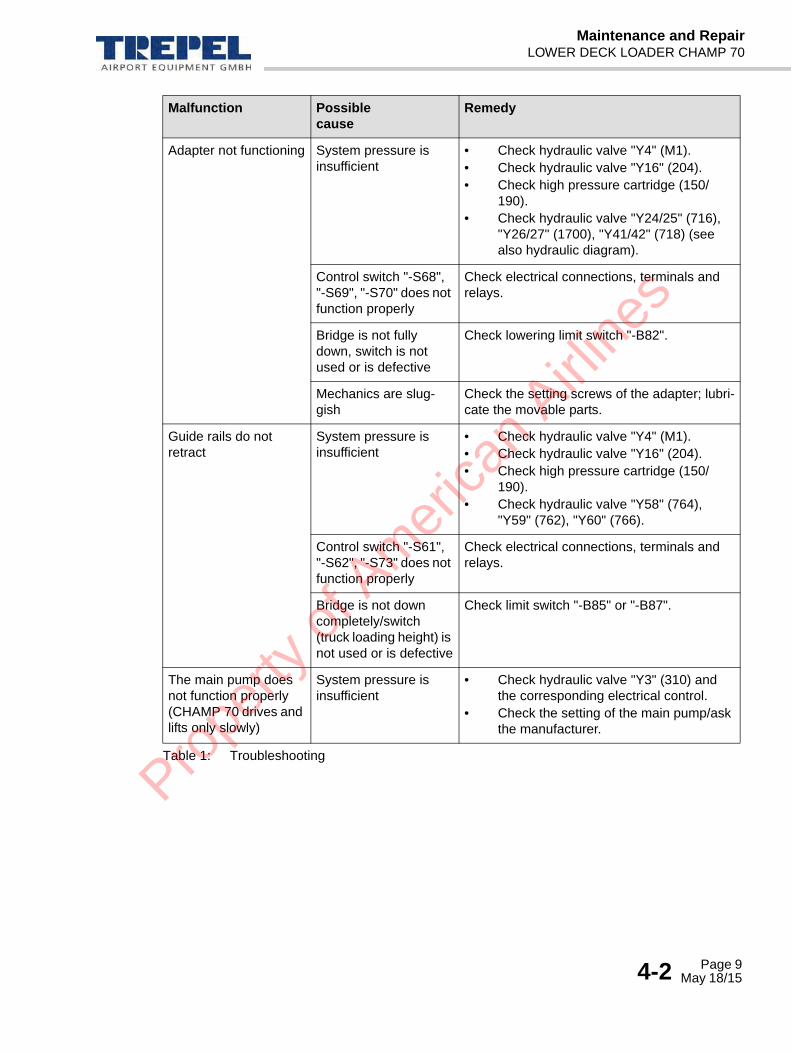
Maintenance and Repair LOWER DECK LOADER CHAMP 70
Table 1: Troubleshooting
Adapter not functioning System pressure is insufficient
• Check hydraulic valve "Y4" (M1).• Check hydraulic valve "Y16" (204).• Check high pressure cartridge (150/
190).• Check hydraulic valve "Y24/25" (716),
"Y26/27" (1700), "Y41/42" (718) (see also hydraulic diagram).
Control switch "-S68", "-S69", "-S70" does not function properly
Check electrical connections, terminals and relays.
Bridge is not fully down, switch is not used or is defective
Check lowering limit switch "-B82".
Mechanics are slug-gish
Check the setting screws of the adapter; lubri-cate the movable parts.
Guide rails do not retract
System pressure is insufficient
• Check hydraulic valve "Y4" (M1).• Check hydraulic valve "Y16" (204).• Check high pressure cartridge (150/
190).• Check hydraulic valve "Y58" (764),
"Y59" (762), "Y60" (766).
Control switch "-S61", "-S62", "-S73" does not function properly
Check electrical connections, terminals and relays.
Bridge is not down completely/switch (truck loading height) is not used or is defective
Check limit switch "-B85" or "-B87".
The main pump does not function properly (CHAMP 70 drives and lifts only slowly)
System pressure is insufficient
• Check hydraulic valve "Y3" (310) and the corresponding electrical control.
• Check the setting of the main pump/ask the manufacturer.
Malfunction Possible cause
Remedy
Prope
rty o
f Am
erica
n Airli
nes
Page 94-2 May 18/15

Maintenance and RepairLOWER DECK LOADER CHAMP 70
This page intentionally left blank.
Prope
rty o
f Am
erica
n Airli
nes
Page 10(Blank) May 18/154-2
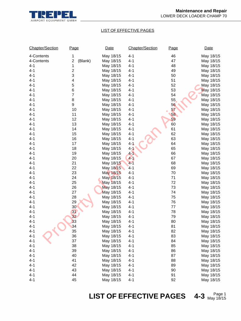
LIST OF EFFECTIVE PAGES
Chapter/Section Page Date Chapter/Section Page Date
Maintenance and Repair LOWER DECK LOADER CHAMP 70
4-Contents 1 May 18/154-Contents 2 (Blank) May 18/154-1 1 May 18/154-1 2 May 18/154-1 3 May 18/154-1 4 May 18/154-1 5 May 18/154-1 6 May 18/154-1 7 May 18/154-1 8 May 18/154-1 9 May 18/154-1 10 May 18/154-1 11 May 18/154-1 12 May 18/154-1 13 May 18/154-1 14 May 18/154-1 15 May 18/154-1 16 May 18/154-1 17 May 18/154-1 18 May 18/154-1 19 May 18/154-1 20 May 18/154-1 21 May 18/154-1 22 May 18/154-1 23 May 18/154-1 24 May 18/154-1 25 May 18/154-1 26 May 18/154-1 27 May 18/154-1 28 May 18/154-1 29 May 18/154-1 30 May 18/154-1 31 May 18/154-1 32 May 18/154-1 33 May 18/154-1 34 May 18/154-1 35 May 18/154-1 36 May 18/154-1 37 May 18/154-1 38 May 18/154-1 39 May 18/154-1 40 May 18/154-1 41 May 18/154-1 42 May 18/154-1 43 May 18/154-1 44 May 18/154-1 45 May 18/15
4-1 46 May 18/154-1 47 May 18/154-1 48 May 18/154-1 49 May 18/154-1 50 May 18/154-1 51 May 18/154-1 52 May 18/154-1 53 May 18/154-1 54 May 18/154-1 55 May 18/154-1 56 May 18/154-1 57 May 18/154-1 58 May 18/154-1 59 May 18/154-1 60 May 18/154-1 61 May 18/154-1 62 May 18/154-1 63 May 18/154-1 64 May 18/154-1 65 May 18/154-1 66 May 18/154-1 67 May 18/154-1 68 May 18/154-1 69 May 18/154-1 70 May 18/154-1 71 May 18/154-1 72 May 18/154-1 73 May 18/154-1 74 May 18/154-1 75 May 18/154-1 76 May 18/154-1 77 May 18/154-1 78 May 18/154-1 79 May 18/154-1 80 May 18/154-1 81 May 18/154-1 82 May 18/154-1 83 May 18/154-1 84 May 18/154-1 85 May 18/154-1 86 May 18/154-1 87 May 18/154-1 88 May 18/154-1 89 May 18/154-1 90 May 18/154-1 91 May 18/154-1 92 May 18/15
Prope
rty o
f Am
erica
n Airli
nes
Page 1LIST OF EFFECTIVE PAGES 4-3 May 18/15

Maintenance and RepairLOWER DECK LOADER CHAMP 70
Chapter/Section Page Date Chapter/Section Page Date
4-1 93 May 18/154-1 94 May 18/154-1 95 May 18/154-1 96 May 18/154-1 97 May 18/154-1 98 May 18/154-1 99 May 18/154-1 100 May 18/154-1 101 May 18/154-1 102 May 18/154-1 103 May 18/154-1 104 May 18/154-1 105 May 18/154-1 106 May 18/154-1 107 May 18/154-1 108 May 18/154-1 109 May 18/154-1 110 May 18/154-1 111 May 18/154-1 112 May 18/154-1 113 May 18/154-1 114 May 18/154-1 115 May 18/154-1 116 May 18/154-1 117 May 18/154-1 118 May 18/154-1 119 May 18/154-1 120 May 18/154-1 121 May 18/154-1 122 May 18/154-1 123 May 18/154-1 124 May 18/154-1 125 May 18/154-1 126 May 18/154-1 127 May 18/154-1 128 May 18/154-1 129 May 18/154-1 130 May 18/154-1 131 May 18/154-1 132 May 18/154-1 133 May 18/154-1 134 May 18/154-1 135 May 18/154-1 136 May 18/154-1 137 May 18/154-1 138 May 18/154-1 139 May 18/15
4-1 140 May 18/154-1 141 May 18/154-1 142 May 18/154-1 143 May 18/154-1 144 May 18/154-1 145 May 18/154-1 146 May 18/154-1 147 May 18/154-1 148(Blank) May 18/154-1 149 May 18/154-1 150 May 18/154-1 151 May 18/154-1 152 May 18/154-1 153 May 18/154-1 154 May 18/154-1 155 May 18/154-1 156 May 18/154-2 1 May 18/154-2 2 May 18/154-2 3 May 18/154-2 4 May 18/154-2 5 May 18/154-2 6 May 18/154-2 7 May 18/154-2 8 May 18/154-2 9 May 18/154-2 10 (Blank) May 18/154-3 1 May 18/154-3 2 May 18/15
Prope
rty o
f Am
erica
n Airli
nes
Page 2LIST OF EFFECTIVE PAGES 4-3 May 18/15