proposal for a technology-neutral safety approach … · iaea-tecdoc-1570 proposal for a...
TRANSCRIPT

IAEA-TECDOC-1570
Proposal for a Technology-NeutralSafety Approach for
New Reactor Designs
September 2007

IAEA SAFETY RELATED PUBLICATIONS
IAEA SAFETY STANDARDS
Under the terms of Article III of its Statute, the IAEA is authorized to establish or adopt standards of safety for protection of health and minimization of danger to life and property, and to provide for the application of these standards.
The publications by means of which the IAEA establishes standards are issued in the IAEA Safety Standards Series. This series covers nuclear safety, radiation safety, transport safety and waste safety, and also general safety (i.e. all these areas of safety). The publication categories in the series are Safety Fundamentals, Safety Requirementsand Safety Guides.
Safety standards are coded according to their coverage: nuclear safety (NS), radiation safety (RS), transport safety (TS), waste safety (WS) and general safety (GS).
Information on the IAEA’s safety standards programme is available at the IAEA Internet site
http://www-ns.iaea.org/standards/
The site provides the texts in English of published and draft safety standards. The texts of safety standards issued in Arabic, Chinese, French, Russian and Spanish, the IAEA Safety Glossary and a status report for safety standards under development are also available. For further information, please contact the IAEA at P.O. Box 100, A-1400 Vienna, Austria.
All users of IAEA safety standards are invited to inform the IAEA of experience in their use (e.g. as a basis for national regulations, for safety reviews and for training courses) for the purpose of ensuring that they continue to meet users’ needs. Information may be provided via the IAEA Internet site or by post, as above, or by e-mail to [email protected].
OTHER SAFETY RELATED PUBLICATIONS
The IAEA provides for the application of the standards and, under the terms of Articles III and VIII.C of its Statute, makes available and fosters the exchange of information relating to peaceful nuclear activities and serves as an intermediary among its Member States for this purpose.
Reports on safety and protection in nuclear activities are issued in other publications series, in particular the Safety Reports Series. Safety Reports provide practical examples and detailed methods that can be used in support of the safety standards. Other IAEA series of safety related publications are the Provision for the Application of Safety Standards Series, the Radiological Assessment Reports Series and the International Nuclear Safety Group’s INSAG Series. The IAEA also issues reports on radiological accidents and other special publications.
Safety related publications are also issued in the Technical Reports Series, the IAEA-TECDOC Series, the Training Course Series and the IAEA Services Series, and as Practical Radiation Safety Manuals and Practical Radiation Technical Manuals.Security related publications are issued in the IAEA Nuclear Security Series.

IAEA-TECDOC-1570
Proposal for a Technology-NeutralSafety Approach for
New Reactor Designs
September 2007
The originating Section of this publication in the IAEA was:
Engineering Safety Section International Atomic Energy Agency
Wagramer Strasse 5 P.O. Box 100
A-1400 Vienna, Austria
PROPOSAL FOR A TECHNOLOGY-NEUTRAL SAFETY APPROACH FOR NEW REACTOR DESIGN
IAEA, VIENNA, 2007 IAEA-TECDOC-1570
ISBN 978–90–0–107607–6 ISSN 1011–4289
© IAEA, 2007
Printed by the IAEA in Austria September 2007
FOREWORD
Many states are considering an expansion of their nuclear power generation programmes. Many of the technologies and concepts are new and innovative. The current design and licensing rules are applicable to mostly large water reactors and there are no accepted rules in place for design, safety assessment and licensing for new innovative nuclear power plants. This TECDOC proposes a (new) safety approach and a methodology to generate technology-neutral (i.e. independent of reactor technology) safety requirements and a “safe design” for advanced and innovative reactors.
The experience gained in decades of design and licensing, combined with the development of risk-based concepts, has provided insights that will form the basis for new safety rules and requirements. Many lessons learned acknowledge the importance of such concepts as safety goals and defence in depth and the benefits of integrating risk insights early in an iterative design process. A new safety approach will incorporate many of the new developments in these concepts. For example, the probabilistic elements of defence in depth will help define the cumulative provisions to compensate for uncertainty and incompleteness of our knowledge of accident initiation and progression.
This TECDOC also identifies areas of work, which will require further definition, research and development and guidance on application.
This publication is to be used as a guide to developing a new technology-neutral safety approach, and as a guide in the application of methodologies to define the safety requirements for an innovative reactor designs. The method proposes an integration of deterministic and probabilistic considerations with established principles and concepts such as safety goals and defence in depth.
The TECDOC recommends that the structure of the new technology-neutral main pillars for the design and licensing of innovative nuclear reactors be developed following a top-down approach to reflect a newer risk-informed and less prescriptive technology-neutral framework. The TECDOC describes an overall strategy to define safety requirements (and a safe design), which are both technology-neutral and technology-specific. However, this TECDOC focuses primarily on the development of technology-neutral safety requirements.
This TECDOC does not establish specific quantitative safety goals.
Ultimately, this work may lead to a set of safety requirements, subjected to a consensus process similar to that existing for current NPPs. It is also expected that this TECDOC will provide useful input to the current process for the review of the IAEA Safety Standards Series No. NS-R-1 (The Safety of Nuclear Power Plants: Design).
This publication has been prepared by a group of experts from a select number of interested Member States and at this stage does not reflect the results of a large consensus process.
The IAEA officer responsible for this publication was M. Gasparini of the Division of Nuclear Installation Safety.
.

EDITORIAL NOTE
The use of particular designations of countries or territories does not imply any judgement by the publisher, the IAEA, as to the legal status of such countries or territories, of their authorities and institutions or of the delimitation of their boundaries.
The mention of names of specific companies or products (whether or not indicated as registered) does not imply any intention to infringe proprietary rights, nor should it be construed as an endorsement or recommendation on the part of the IAEA.

CONTENTS
1. INTRODUCTION ............................................................................................................ 1
1.1. Background......................................................................................................... 1 1.2. Objective............................................................................................................. 3 1.3. Scope .................................................................................................................. 4 1.4. Structure.............................................................................................................. 4
2. MODEL TO DEVELOP SAFETY REQUIREMENTS FOR NEW NUCLEAR POWER PLANTS ............................................................................................................ 5
2.1. Current IAEA Safety Approach ......................................................................... 7 2.2. Current IAEA Safety Standards ......................................................................... 8 2.3. Developing a New IAEA Safety Approach........................................................ 8
2.3.1. Case study to implement technology-neutral defence in depth .............. 8
2.4. Proposed New IAEA Safety Approach .............................................................. 9 2.4.1. Safety Objectives .................................................................................. 10 2.4.2. Quantitative Safety Goals ..................................................................... 11 2.4.3. Fundamental Safety Functions.............................................................. 13 2.4.4. Defence in Depth .................................................................................. 13
3. A METHODOLOGY TO GENERATE TECHNOLOGY-NEUTRAL SAFETY REQUIREMENTS AND DESIGN ................................................................................ 20
3.1. Plant Conditions and Design Basis................................................................... 20 3.1.1 Normal Operating Conditions............................................................... 21 3.1.2 Abnormal Operating Conditions........................................................... 21 3.1.3 Anticipated Operational Occurrences ................................................... 21 3.1.4 Accident Conditions ............................................................................. 22 3.1.5 Severe Plant Conditions........................................................................ 22 3.1.6 Accident Management .......................................................................... 22
3.2 Applying Objectives Provisions Tree Method ................................................. 22 3.3 Design Process for Innovative Reactor Designs............................................... 23
APPENDIX I: SAMPLE PROPOSAL OF TECHNOLOGY-NEUTRAL REQUIREMENTS (BASED ON CRITICAL REVIEW OF NS-R-1) ............ 29
APPENDIX II: POSTULATED INITIATING EVENTS ....................................................... 65
APPENDIX III: REDUNDANCY, DIVERSITY AND INDEPENDENCE........................... 68
APPENDIX IV: DEFENCE IN DEPTH.................................................................................. 71
GLOSSARY............................................................................................................................. 77
REFERENCES......................................................................................................................... 79
CONTRIBUTORS TO DRAFTING AND REVIEW ............................................................. 81

1. INTRODUCTION
1.1. Background
The different design approaches, technologies and safety features of advanced nuclear concepts indicate that the full application of existing safety requirements, mostly developed for large water cooled reactors will need, in some cases, extensive interpretation or adaptation. For some innovative concepts there is a need to develop a tailored set of safety requirements derived from the general consolidated principles of nuclear safety, which better incorporates the specific characteristics of a given concept. The framework for new plant design, safety assessment and licensing will need to include designs with little resemblance to current water reactor designs. These designs may lie far beyond the current design, operating and licensing knowledge base and experience. Furthermore, there is an expectation that the safety of innovative nuclear power plants will be demonstrated to be improved when compared to existing installations. For example, the IAEA-sponsored project INPRO (International Project on Innovative Nuclear Reactors and Fuel Cycles) has identified such expectations in its recent publications.
This TECDOC identifies some of the key areas where change and development are required to the current design and licensing rules (for water power reactors), in order to design and license future innovative reactor designs. This TECDOC proposes a framework (the Main Pillars of a new Safety Approach) from which to develop both technology-neutral and technology-specific requirements.
The experience gained in decades of design and licensing combined with the development of risk-based concepts has provided insights that will form the basis for new safety rules and requirements. Many lessons learned acknowledge the importance and continuous development of such concepts as safety goals and defence in depth, and the benefits of integrating risk insights early in an iterative design process.
This TECDOC recommends that the structure of the current Main Pillars for the Design and Licensing of Current Water Nuclear Reactors (see Section 2.1) be developed to reflect a more risk-informed and less prescriptive technology-neutral framework (Main Pillars of a New Approach) for new reactor designs.
This TECDOC also describes an overall strategy for a process to develop safety requirements for new reactor designs. The set of requirements will consist of both technology-neutral and technology-specific requirements. However, this TECDOC focuses primarily on the development of technology-neutral safety requirements.
The existing IAEA Safety Standards and the ongoing work on implementation of defence in depth for different reactor types provide a useful starting point to develop a technology-neutral safety approach. The proposed new Safety Approach is an evolution of existing design and licensing rules and safety approach.
The following areas requiring further development were identified:
1. Qualitative Safety Objective to be replaced by Quantitative Safety Goals
Quantitative Safety Goals expressed by means of a frequency-consequence diagram derived from the Safety Objectives will be developed in terms of allowable frequency with which, each level of consequences can be exceeded.
1

2. Enhanced Defence in Depth (DiD)
The principle that nuclear safety aims to prevent or limit radiological exposure by application of defence in depth is well documented in INSAG reports and IAEA standards and guidelines. This principle is fundamental to the establishment of safety requirements for nuclear facilities of all types, application to design, construction and operation.
As part of the basic approach to safety, it will be required to incorporate an enhanced defence in depth with more independence of the different levels of protection, and with an increased emphasis on inherent safety characteristics and passive safety features. The implementation of DiD will require a new approach that would be based on a more advanced interpretation of DiD fully integrated with PSA insights.
While defence in depth as a concept is technology-neutral, and the principles and approaches are also technology-neutral, there will be some technology-specific considerations as a result of applying the defence in depth to a specific reactor design.
3. Enhanced Levels of Defence in Depth will be correlated with Quantitative Safety Goals
Quantitative Safety Goals targets will be correlated at each level of defence in depth and will take account of probabilistic considerations.
4. Further Development of Probabilistic Safety Analyses (PSA)
Further development of PSA methods, including best estimate plus uncertainty analysis, and their supporting databases are required and need to be capable of:
• Assessing innovative designs implemented with lines of defence composed of inherent safety characteristics and passive, as well as active systems.
• Assessing total risk from various states, full power, low power, and shutdown, considering both internal and external events.
• Accounting for, human factors, and ageing effects.
• Quantifying the effects of random data and modelling uncertainties.
5. Further Development of a Sound and Well Balanced Safety Classification of Safety Systems and Components
It is expected that by utilizing probabilistic considerations and insights in the implementation of the DiD, a sound and well balanced Safety Classification of Safety Systems and Components will be developed, using a graded approach.
6. How to Define Research, Development and Demonstration (RD&D)
RD&D to comply with technology-specific safety requirements must be identified and carried out using engineering test facilities, possibly pilot plants, to bring the knowledge of plant characteristics and the capability of codes used for safety analysis of innovative designs to the same level as for existing plants. Innovative designs will be supported by the results of
2

relevant research programmes, which shall provide adequate evidence that the safety claims are justified.
7. Application of Methodologies early in the Design Process to Systematically Examine Risk and Options of Solutions such as the Objectives Provisions Tree Methodology
The Objectives Provisions Tree is an example of a methodology that systematically examines all possible options for provisions to prevent and/or control mechanisms that are to be prevented or controlled based on the structured hierarchic Defence in Depth framework. Two case studies implementing this methodology have been completed by the IAEA to demonstrate its capability and effectiveness (Safety Reports Series No. 46 – Assessment of Defence in Depth for Nuclear Power Plants [1] and IAEA TECDOC-1366 – Considerations in the Development of Safety Requirements: Application to Modular High Temperature Gas Cooled Reactors [2]).
Following a structured application of the objectives provisions tree will identify specific features or materials which could initiate events for which technology-specific safety requirements will be generated to provide specific preventive or mitigative measures.
8. Application of Iterative Design Processes to demonstrate that Adequate Defence in Depth is achieved (Safety driven design process).
Iterative design processes will be developed to implement the results of the Objectives Provisions Tree. When a complete set of protective features (systems, procedures, etc.) has been designed based on a given set of the previous ones resulting, for example, from protection failures, screening criteria, similar to those used to filter-out very unlikely initiating events, should be applied to degraded plant states.
The consideration of these new plant states may result in unsuccessful verification of compliance with the quantitative safety goal. This leads to an iterative design-verification process, whose convergence should be ensured by an adequate selection of the screening criteria.
9. Comprehensive Review of Existing Safety Approach
The current safety approach is the result of many decades of design and licensing experience. A comprehensive review of well-established safety requirements, such as NS-R-1 [3] can provide important input and insights to the development of a comprehensive set of new requirements. (Appendix I is an example of such a review by a working group at IAEA to modify NS-R-1 to the degree necessary to make the standard technology-neutral and reflect a more risk informed performance based approach).
1.2. Objective The fundamental objective of this document is to provide a technology-neutral safety approach that will guide the design, safety assessment and licensing of innovative reactors.
This TECDOC outlines a methodology/process:
• to develop a new framework (Main Pillars of a new Safety Approach) and
3

• to generate the safety requirements (consisting of both technology-neutral and technology-specific).
• to develop a “safety-driven” plant design which complies with the new Safety Approach and the newly derived safety requirements.
An objective of this report is also to identify the, areas of work and processes discussed in the document, but which need further research and developed or modifications. These are identified in the Scope section of this document. The objective is not to develop these concepts as part of this document, but identify where there may be gaps in some of the methodologies and “tools”. For example, this TECDOC recommends that quantitative safety goals be implemented, but does not establish specific quantitative safety goals.
The intent of this document is that it be used as a guide to develop the new safety approach, design requirements and a safe design.
This document has been prepared by a group of experts from a select number of interested Member States and at this stage does not reflect the results of a large consensus process.
Ultimately, this work may lead to a set of safety requirements, subjected to a consensus process similar to that existing for current NPPs.
1.3. Scope
The proposed safety approach is intended for use by organizations designing, manufacturing, constructing and operating nuclear power plants as well as by regulatory bodies.
It is expected that this publication will be used primarily for nuclear power plants designed for electricity generation or other heat production applications (such as district heating, hydrogen generation or desalination). The current version does not cover fuel cycle aspects of those plants operating on a closed fuel cycle, although it is considered that the proposed approach could also be applicable to such systems.
This safety approach addresses the potential risk during any mode of plant operation, and also the potential risk from internal and external events that can challenge the integrity of the plant design and the continued operation of the plant.
This TECDOC also identifies areas/issues where additional work (scope) is required for better definition of concepts and for planning, research and development. This TECDOC examines these issues in the context of defining the overall process to generate the new Safety Approach; however the development of each of these areas of work is not within the scope of this report.
1.4. Structure
Section 2 describes the model and process to develop safety requirements for new NPPs. This section also summarizes the IAEA hierarchy of Safety Standards and the “safety approach” (main pillars) for current water nuclear power plants. This section references a recent case study (IAEA) which identifies that while there are limitations of the current safety approach for new NPPS, the main concepts (pillars) underpinning the current safety approach may be suitable if properly re-formulated/enhanced and developed. A proposed revised “Safety Approach” for new NPPs, is discussed. The proposed new “Pillars of the Safety Approach”
4

for new NPPs are: (1) quantitative safety goals, (2) fundamental safety functions (unchanged), and (3) defence in depth (which include probabilistic considerations).
Section 3 discusses the applications of methodologies (combined deterministic and probabilistic) to generate safety requirements for new NPPs (Technology-Neutral). This section introduces relatively modern concepts/tools such as “Objectives Provisions Trees to systematically review the implementation of the defence in depth, and a design process for innovative designs. The design process is the implementation of the Objectives Provisions Tree to confirm that adequate Defence in Depth has been achieved.
Appendix I contains a sample proposal of Technology-neutral Requirements based on a critical review of the Safety Requirements NS-R-1; Appendix II describes the use of postulated initiating events (PIE); Appendix III describes redundancy, diversity and independence; and Appendix IV provides an overview of defence in depth.
2. MODEL TO DEVELOP SAFETY REQUIREMENTS FOR NEW NUCLEAR POWER PLANTS
This section describes the process to derive the design and licensing rules for innovative reactor designs. The current safety approach is described. The new approach is “evolved” from the current safety approach (main pillars) by critically reviewing each of the main pillars while incorporating probabilistic considerations. The following describes the elements of Figure 1.
MAIN PILLARS (New Approach)
• SAFETY GOAL
• FUNDAMENTAL SAFETY FUNCTIONS
• DEFENCE IN DEPTH (Generalized) which includes probabilistic
considerations
MAIN PILLARS (New Approach)
• QUANTITATIVE SAFETY GOAL
• FUNDAMENTAL SAFETY FUNCTIONS• DEFENCE IN DEPTH (Generalized)
which includes probabilistic considerations
Requirements(General)
Requirements(Specific)
MAIN PILLARS (Current Approach)
• SAFETY OBJECTIVES
• FUNDAMENTAL SAFETY FUNCTIONS
• DEFENCE IN DEPTH (Deterministic)
• PSA
MAIN PILLARS (Current Approach)
• QUALITATIVE SAFETY OBJECTIVES
• FUNDAMENTAL SAFETY FUNCTIONS
• DEFENCE IN DEPTH (Deterministic)
• PSA
NEW APPROACH- MORE RISK INFORMED
- LESS PRESCRIPTIVE
1) Understanding:
- the rationale behind each requirement
- the contribution of each requirements to defence in depth
-whether the requirement is technology-neutral or technology-dependent
2) Application of the Objective-Provisions Tree
CRITICAL REVIEW
Requirements(General)
Requirements(Specific)
Technology neutral
Technology dependent
Recommendationsfor the Design
Recommendationsfor the Design
SafetyRequirements(SS NS-R-1)
Safety Guides(SS NS-G-1…)
DESIGN AND LICENSING RULES FOR CURRENT
WATER REACTORS
DESIGN AND LICENSING RULES FOR A GIVEN
INNOVATIVE REACTOR
(1)
(3)
(4)
(2)
(5)
(6)
MAIN PILLARS (New Approach)
• SAFETY GOAL
• FUNDAMENTAL SAFETY FUNCTIONS
• DEFENCE IN DEPTH (Generalized) which includes probabilistic
considerations
MAIN PILLARS (New Approach)
• QUANTITATIVE SAFETY GOAL
• FUNDAMENTAL SAFETY FUNCTIONS• DEFENCE IN DEPTH (Generalized)
which includes probabilistic considerations
Requirements(General)
Requirements(Specific)
MAIN PILLARS (Current Approach)
• SAFETY OBJECTIVES
• FUNDAMENTAL SAFETY FUNCTIONS
• DEFENCE IN DEPTH (Deterministic)
• PSA
MAIN PILLARS (Current Approach)
• QUALITATIVE SAFETY OBJECTIVES
• FUNDAMENTAL SAFETY FUNCTIONS
• DEFENCE IN DEPTH (Deterministic)
• PSA
NEW APPROACH- MORE RISK INFORMED
- LESS PRESCRIPTIVE
1) Understanding:
- the rationale behind each requirement
- the contribution of each requirements to defence in depth
-whether the requirement is technology-neutral or technology-dependent
2) Application of the Objective-Provisions Tree
CRITICAL REVIEW
Requirements(General)
Requirements(Specific)
Technology neutral
Technology dependent
Recommendationsfor the Design
Recommendationsfor the Design
SafetyRequirements(SS NS-R-1)
Safety Guides(SS NS-G-1…)
DESIGN AND LICENSING RULES FOR CURRENT
WATER REACTORS
DESIGN AND LICENSING RULES FOR A GIVEN
INNOVATIVE REACTOR
MAIN PILLARS (New Approach)
• SAFETY GOAL
• FUNDAMENTAL SAFETY FUNCTIONS
• DEFENCE IN DEPTH (Generalized) which includes probabilistic
considerations
MAIN PILLARS (New Approach)
• QUANTITATIVE SAFETY GOAL
• FUNDAMENTAL SAFETY FUNCTIONS• DEFENCE IN DEPTH (Generalized)
which includes probabilistic considerations
Requirements(General)
Requirements(Specific)
MAIN PILLARS (Current Approach)
• SAFETY OBJECTIVES
• FUNDAMENTAL SAFETY FUNCTIONS
• DEFENCE IN DEPTH (Deterministic)
• PSA
MAIN PILLARS (Current Approach)
• QUALITATIVE SAFETY OBJECTIVES
• FUNDAMENTAL SAFETY FUNCTIONS
• DEFENCE IN DEPTH (Deterministic)
• PSA
NEW APPROACH- MORE RISK INFORMED
- LESS PRESCRIPTIVE
1) Understanding:
- the rationale behind each requirement
- the contribution of each requirements to defence in depth
-whether the requirement is technology-neutral or technology-dependent
2) Application of the Objective-Provisions Tree
CRITICAL REVIEW
Requirements(General)
Requirements(Specific)
Technology neutral
Technology dependent
Recommendationsfor the Design
Recommendationsfor the Design
SafetyRequirements(SS NS-R-1)
Safety Guides(SS NS-G-1…)
DESIGN AND LICENSING RULES FOR CURRENT
WATER REACTORS
DESIGN AND LICENSING RULES FOR A GIVEN
INNOVATIVE REACTOR
(1)
(3)
(4)
(2)
(5)
(6)
(1)
(3)
(4)
(2)
(5)
(6)
Figure 1. Model to develop safety requirements for new NPPs.
5

Figure 1 (1) shows the foundation of the current safety philosophy, namely the main pillars (safety objectives, fundamental safety functions, deterministic defence in depth and application of PSA) developed over many decades and incorporating the results of extensive plant operating experience and experience gained from lessons learned. The current IAEA rules for designing and licensing (2) are defined and embodied in the Safety Requirements NS-R-1 and the series of accompanying Safety Guides.
The existing main pillars (1), are subjected to a critical review (5) and then adapted to propose new main pillars (4) which will encompass a range of potential developments in innovative reactor technologies, incorporating a risk informed approach, and verification that they are technology-neutral. The proposed new pillars (discussed in detail later in this TECDOC), include quantitative safety goals, fundamental safety functions and quantitative targets to be achieved at each level of defence in depth (taking into account probabilistic considerations).
The final stage of the process (5) is a critical review of the current IAEA light water based requirements (NS-R-1) to develop a generalized safety philosophy that provides the safety goal and principles, which define a desirable level of protection of site personnel, the public and the environment, from the nuclear plant, from which the safety requirements (6) are developed.
The critical review of the existing requirements for nuclear power plants starts from the most general (already applicable to all nuclear plants, i.e. technology-neutral) and works down to the most specific and more technology dependent, as shown in Figure 1.
The objective of the review is to determine whether the requirements found in the reference documents are technology-neutral and risk informed, and whether there are any potential changes which could be made to facilitate such an interpretation.
The criterion for review of the high-level safety objectives is relatively straightforward. The high-level safety objectives are reviewed to determine whether they are indeed technology-neutral. It is to be expected that the existing safety objectives will apply to all reactors. The general safety requirements as found in NS-R-1 are evaluated based on whether they are technology-neutral and whether they are risk informed in accordance with the approach to defence in depth described in Appendix IV. Some of the requirements that are water reactor technology based are modified to reflect a more functional safety mission focus rather than a specific system.
The set of requirements may not be comprehensive because of their light water reactor technology origin. Their completeness depends on how well the critical review extrapolated from light water reactor based requirements to technology-neutral requirements, and on how well the guidance for implementing the safety philosophy on a technology-neutral basis ensured that additional requirements, not based on light water requirements, were included in the set.
A set of proposed technology-neutral safety requirements derived by the process described in this section is provided in Appendix I.
The key steps in this process are to ensure that the fundamental requirements described in NS-R-1 and subsequently modified, do not specifically refer to light water reactor applications. If specific requirements are mentioned, they should be reliability based and focused on performance of function (e.g. not overheating the core) rather than number of redundant
6
systems required or the need for specific systems (emergency core cooling for example). Such systems may ultimately be required but that will depend on the reactor design chosen, its performance subject to the challenges identified, and the state of knowledge of the innovative technology. The requirements of NS-R-1 are thus modified to reflect the technology-neutral approach that leads to a comprehensive set of requirements that can be applied to any reactor design.
Many of the fundamental requirements of NS-R-1 remain since they are generically applicable to all reactor types. These include requirements for the management of safety, general good engineering practices such as the design of control rooms, fuel handling and storage systems, radiation protection, etc. provided that they are sufficiently general in nature to accommodate different reactor concepts. However, it should be noted that some LWR based requirements, such as the single failure criterion and multiple barriers to the release of radioactive materials to the environment, may not necessarily be applicable to a technology-neutral application if it can be shown with sufficient confidence that because of the passive nature of a design, a lower level of protection may be adequate to achieve the safety goal.
The safety requirements (6) are composed of technology-neutral and technology-specific requirements. Technology-neutral requirements are applicable to any type of reactor on a technology-neutral basis (If the derived safety requirements is not technology-neutral, then the safety requirement is revised and modified accordingly). Technology-specific requirements are applied to a specific reactor design. The Requirements for a specific type of reactor are generated through a critical interpretation of the objectives, challenges to the objectives, mechanisms posing the challenges and corresponding provisions associated with each level of defence in depth and the full understanding of the safety features of the specific reactor. For each level of defence in depth, and for each safety function, the objectives provisions tree (described later in this TECDOC) is the instrument to perform this task. A comprehensive approach is required which will lead to the identification of specific or totally new requirements. The application of the objectives provisions tree methodology will lead to the compilation of a consistent set of requirements organized in a hierarchical way with the general requirements at the top and the more specific at the bottom like those existing for current plants.
A comparison with currently available, well established safety requirements, such as NS-R-1 can provide a further important input to the development of a comprehensive set of requirements which are specific to the new technology, even though it contains requirements as they would be applied to light water reactors.
(The implementation of technology-specific requirements is out of scope of this document).
2.1. Current IAEA Safety Approach
All of the existing safety rules have been developed according to a safety approach or safety philosophy based on a set of main concepts (pillars). The “main pillars” (see Figure 1) that underpin the current Safety Approach, embodied in NS-R-1 are:
• Qualitative Safety Objectives of the general nuclear safety, the radiation safety, and the technical safety;
• Fundamental Safety Functions to be achieved for the plant, which are the confinement of radioactive material, control of reactivity, and the removal of heat from the core;
7

• The application of Defence in Depth, which requires several levels of protection to be provided that include multiple barriers to the release of radioactive materials, and the provision of safety systems designed to ensure the safe shutdown of the reactor; and
• The application of Probabilistic Safety Assessment techniques, which complement the deterministic methods.
2.2. Current IAEA Safety Standards
Under the terms of its Statute, the IAEA is authorized to establish standards of safety for protection against ionizing radiation. The IAEA has published the Safety Standards Series for nuclear power plants to be used by regulatory bodies, government agencies and organizations that design and operate nuclear power plants. The safety requirements and recommendations included in the IAEA Safety Standards provide a set of rules that reflect the current practice and experience of the Member States for designing and licensing nuclear power plants. These requirements have reached the current status through a long development process, which has incorporated the results of extensive plant operating experience and the experience gained from the lessons of the past. The hierarchy (Safety Approach) of Safety Standards for the Design of current NPP consists of three levels of governing documents:
Safety Fundamentals: present the basic objective and principles of radiation protection and nuclear safety.
Safety Requirements: establish the requirements that must be met to ensure safety. These requirements, which are expressed, as “shall” statements, are governed by the objectives and principles presented in the Safety Fundamentals.
Safety Guides: recommend actions, conditions or procedures for meeting safety requirements. Recommendations in Safety Guides are expressed as “should” statements, with the implication that it is necessary to take the measures recommended or equivalent measures to comply with the requirements.
2.3. Developing a New IAEA Safety Approach
2.3.1. Case study to implement technology-neutral defence in depth
A recent case study performed by the IAEA, IAEA-TECDOC-1366 “Considerations in the Development of Safety Requirements for Innovative Reactors: Application to Modular High Temperature Gas Cooled Reactors” – August 2003 [2], concludes that the main concepts (pillars) underpinning the current safety approach may be suitable for new plants, if properly interpreted and formulated. The case study notes that applying the defence in depth concept in a systematic and comprehensive manner, and correlated to “quantified” safety goals, could provide the assurance that a NPP design is safe, sound and has a balanced defence in depth.
This TECDOC builds upon the insights of this case study, and the expertise from interested Member States, and proposes a new safety approach and a methodology to generate safety requirements for new NPPs, which are technology-neutral, more risk informed and less prescriptive.
8

2.4. Proposed New IAEA Safety Approach
A New Safety Approach for new NPPs is proposed. Each of the “existing main pillars and rational/intent” will be critically reviewed to encompass the range of potential developments in innovative reactor technologies (differentiating between technology-neutral and technology-specific requirements) and incorporate the use of probabilistic considerations. The process is shown in Figure 2. The proposed new main pillars of the New Safety Approach [(4) – Figure 1]: • Quantitative Safety Goals (correlated with each level of Defence in Depth) • Fundamental Safety Functions • Defence in Depth (Generalized) which includes probabilistic considerations)
The foundation of the existing and proposed new safety approach is the safety philosophy, which establishes the safety goal and principles that define a desirable level of protection. Figure 2 outlines the elements that make up the safety philosophy, these are: safety objective, safety goal, safety functions, and defence in depth. The philosophy is based on the safety objectives stated in IAEA NS-R-1 [3]. As indicated in figure 2, it is proposed to recast the “qualitative objectives” in terms of quantitative safety goals, using a frequency versus consequence curve to define acceptable and unacceptable regions of risk. The safety objectives and the quantitative safety goal can be achieved by assuring that the fundamental safety functions of reactivity control, removal of heat, and confinement of radioactive material can each be accomplished with a high degree of confidence. Such confidence can be attained via implementation of defence in depth to assure that each of the fundamental safety functions can be successfully performed in all plant states.
The strategy of defence in depth in nuclear safety is discussed in INSAG-10 [5] in terms of five levels, together with the objective of each level, the essential means of meeting this objective, and the deterministic considerations involved in the implementation of defence in depth. By setting quantitative safety goals (described later in this TECDOC) stated in probabilistic terms, i.e., frequency limits for various consequence levels, enables probabilistic considerations, including success criteria, to be factored into the implementation of defence in depth, as shown in Figure 2. The deterministic and probabilistic considerations are therefore integrated into the comprehensive implementation of defence in depth.
Following is a more detailed discussion of the elements of Figure 2.
9
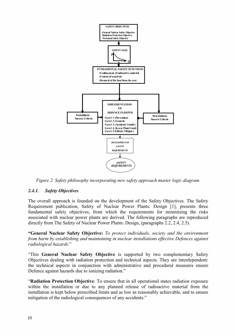
SAFETY OBJECTIVES
•General Nuclear Safety Objective•Radiation Protection Objective•Technical Safety Objective
•Level 3 (Accidents Condit.)
IMPLEMENTATIONOF
DEFENCE IN DEPTH
•Level 1 (Prevention)•Level 2 (Control)
•Level 4 (Severe Plant Cond)•Level 5 (Off-site Mitigat.)-
ProbabilisticSuccess Criteria
DeterministicSuccess Criteria
FUNDAMENTAL SAFETY FUNCTIONS•Confinement of radioactive material•Control of reactivity•Removal of the heat from the core
SAFETY GOAL
SAFETYREQUIREMENTS
DEVELOPMENT OF
SAFETY
REQUIREMENTS
F
C
Figure 2. Safety philosophy incorporating new safety approach master logic diagram.
2.4.1. Safety Objectives
The overall approach is founded on the development of the Safety Objectives. The Safety Requirement publication, Safety of Nuclear Power Plants: Design [1], presents three fundamental safety objectives, from which the requirements for minimising the risks associated with nuclear power plants are derived. The following paragraphs are reproduced directly from The Safety of Nuclear Power Plants: Design, (paragraphs 2.2, 2.4, 2.5).
“General Nuclear Safety Objective: To protect individuals, society and the environment from harm by establishing and maintaining in nuclear installations effective Defences against radiological hazards.”
“This General Nuclear Safety Objective is supported by two complementary Safety Objectives dealing with radiation protection and technical aspects. They are interdependent: the technical aspects in conjunction with administrative and procedural measures ensure Defence against hazards due to ionizing radiation.”
“Radiation Protection Objective: To ensure that in all operational states radiation exposure within the installation or due to any planned release of radioactive material from the installation is kept below prescribed limits and as low as reasonably achievable, and to ensure mitigation of the radiological consequences of any accidents.”
10

“Technical Safety Objective: To take all reasonably practicable measures to prevent accidents in nuclear installations and to mitigate their consequences should they occur; to ensure with a high level of confidence that, for all possible accidents taken into account in the design of the installation, including those of very low probability, any radiological consequences would be minor and below prescribed limits; and to ensure that the likelihood of accidents with serious radiological consequences is extremely low.”
“Safety Objectives require that nuclear installations are designed and operated so as to keep all sources of radiation exposure under strict technical and administrative control. However, the Radiation Protection Objective does not preclude limited exposure of people or the release of legally authorized quantities of radioactive materials to the environment from installations in operational states. Such exposures and releases, however, must be in compliance with operational limits and radiation protection standards.”
In order to demonstrate the achievement of these three safety objectives in the design of a nuclear power plant, a comprehensive safety analysis is carried out to identify all sources of exposure and to evaluate radiation doses that could be received by workers at the installation and the public, as well as potential effects on the environment.
Although measures are taken to control radiation exposure in all operational states to levels as low as reasonably achievable (ALARA) and to minimize the likelihood of an accident that could lead to the loss of normal control of the source of radiation, there is a residual probability that an accident may happen. Measures are therefore taken and provisions are implemented to ensure that the situation is controlled and that the radiological consequences are mitigated. The safety analysis examines: (1) all planned normal operational modes of the plant; (2) plant performance in anticipated operational occurrences; (3) accident conditions; and (4) sequences that may lead to severe plant conditions. On the basis of this analysis, the robustness of the engineering design in withstanding postulated initiating events can be established, the effectiveness of the implemented safety architecture can be demonstrated, and requirements for emergency response can be established.
The safety architecture includes: inherent plant safety features and characteristics; engineered safety features; on-site accident management procedures established by the operating organization; and off-site intervention measures established by appropriate authorities in order to mitigate radiation exposure if an accident has occurred.
2.4.2. Quantitative Safety Goals
This TECDOC proposes that Quantitative Safety Goals (Note: This TECDOC does not establish specific safety goals) be developed and adopted into the overall Safety Philosophy and new Safety Approach.
Quantitative Safety Goals for a design are identified in terms of allowable consequences as function of likelihood; they are derived from the Safety Objectives (i.e. from the Nuclear Safety Objective and the complementary Radiation Protection Objective and Technical Safety Objective) and are expressed in quantitative terms. The approach for assuring the safety of NPP follows the principles that plant states that could result in significant but still allowable radiation doses are of very low frequency, and plant states with significant frequency (likelihood) of occurrence have only minor or no potential radiological consequences (the principle called Farmer’s curve).
11
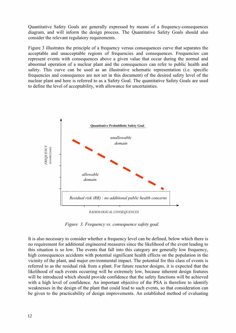
Quantitative Safety Goals are generally expressed by means of a frequency-consequences diagram, and will inform the design process. The Quantitative Safety Goals should also consider the relevant regulatory requirements.
Figure 3 illustrates the principle of a frequency versus consequences curve that separates the acceptable and unacceptable regions of frequencies and consequences. Frequencies can represent events with consequences above a given value that occur during the normal and abnormal operation of a nuclear plant and the consequences can refer to public health and safety. This curve can be used as an illustrative schematic representation (i.e. specific frequencies and consequence are not set in this document) of the desired safety level of the nuclear plant and here is referred to as a Safety Goal. The quantitative Safety Goals are used to define the level of acceptability, with allowance for uncertainties.
RADIOLOGICAL CONSEQUENCES
-FREQ
UEN
CY
(eve
nts/
year
)
unallowabledomain
Figure 3. Frequency vs. consequence safety goal.
Quantitative Probabilistic Safety Goal
allowabledomain
Residual risk (RR) : no additional public health concerns
It is also necessary to consider whether a frequency level can be defined, below which there is no requirement for additional engineered measures since the likelihood of the event leading to this situation is so low. The events that fall into this category are generally low frequency, high consequences accidents with potential significant health effects on the population in the vicinity of the plant, and major environmental impact. The potential for this class of events is referred to as the residual risk from a plant. For future reactor designs, it is expected that the likelihood of such events occurring will be extremely low, because inherent design features will be introduced which should provide confidence that the safety functions will be achieved with a high level of confidence. An important objective of the PSA is therefore to identify weaknesses in the design of the plant that could lead to such events, so that consideration can be given to the practicability of design improvements. An established method of evaluating
12

potential weaknesses such as a PSA sensitivity analysis should be carried out to demonstrate that there is no cliff edge effect1.
2.4.3. Fundamental Safety Functions
The objective of any safety approach for the design and operation of nuclear plants is to achieve the definition of a safety architecture, which provides adequate means:
• to maintain the plant in a normal operational state;
• to ensure the proper short term response immediately following a postulated initiating event (PIE) and;
• to ensure the adequate management of the plant in and following design basis conditions including the “severe plant conditions”.
To ensure safety (i.e. to satisfy the safety goal of meeting allowable radiological consequences during all foreseeable plant conditions), the following fundamental safety functions shall be achieved for all the plant states:
• control of the reactor power; • removal of heat from the fuel; and • confinement of radioactive materials For a given plant state, and for each of the above safety functions, success criteria need to be defined to characterize the corresponding predefined safe plant state. Using these criteria, it is then possible to design the provisions that are required to maintain or to bring back the plant to a safe state.
The accomplishment of these fundamental safety functions is assured by following a defence in depth approach. 2.4.4. Defence in Depth
The concept of defence in depth, as applied to all safety activities, whether organizational, behavioural or design related, ensures that they are subject to functionally redundant provisions, so that if a failure were to occur, it would be detected and compensated for or corrected by appropriate measures. Application of the concept of defence in depth in the design of a plant provides a series of levels of defence (inherent features, equipment and procedures) aimed at preventing accidents and ensuring appropriate protection in the case that prevention fails. This strategy has been proven to be effective in compensating for human and equipment failures, both potential and actual. There is no unique way to implement defence in depth (i.e. no unique technical solution to meet the safety objectives), since there are different designs, different safety requirements in different countries, different technical solutions and varying management or cultural approaches. Nevertheless, the strategy represents the best general framework to achieve safety for any type of nuclear power plant.
1 “Cliff edge effect” is defined as a small change in assumptions, performance or frequency for the plant condition, resulting in large unacceptable consequences.
13
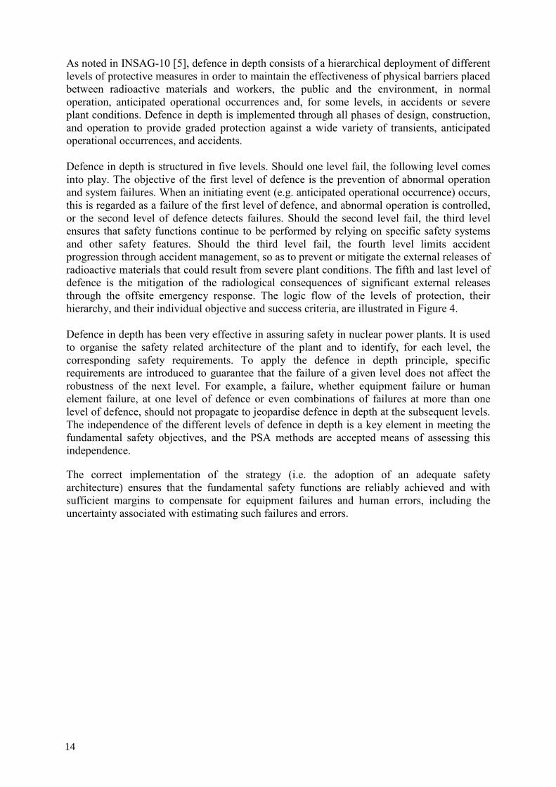
As noted in INSAG-10 [5], defence in depth consists of a hierarchical deployment of different levels of protective measures in order to maintain the effectiveness of physical barriers placed between radioactive materials and workers, the public and the environment, in normal operation, anticipated operational occurrences and, for some levels, in accidents or severe plant conditions. Defence in depth is implemented through all phases of design, construction, and operation to provide graded protection against a wide variety of transients, anticipated operational occurrences, and accidents. Defence in depth is structured in five levels. Should one level fail, the following level comes into play. The objective of the first level of defence is the prevention of abnormal operation and system failures. When an initiating event (e.g. anticipated operational occurrence) occurs, this is regarded as a failure of the first level of defence, and abnormal operation is controlled, or the second level of defence detects failures. Should the second level fail, the third level ensures that safety functions continue to be performed by relying on specific safety systems and other safety features. Should the third level fail, the fourth level limits accident progression through accident management, so as to prevent or mitigate the external releases of radioactive materials that could result from severe plant conditions. The fifth and last level of defence is the mitigation of the radiological consequences of significant external releases through the offsite emergency response. The logic flow of the levels of protection, their hierarchy, and their individual objective and success criteria, are illustrated in Figure 4. Defence in depth has been very effective in assuring safety in nuclear power plants. It is used to organise the safety related architecture of the plant and to identify, for each level, the corresponding safety requirements. To apply the defence in depth principle, specific requirements are introduced to guarantee that the failure of a given level does not affect the robustness of the next level. For example, a failure, whether equipment failure or human element failure, at one level of defence or even combinations of failures at more than one level of defence, should not propagate to jeopardise defence in depth at the subsequent levels. The independence of the different levels of defence in depth is a key element in meeting the fundamental safety objectives, and the PSA methods are accepted means of assessing this independence.
The correct implementation of the strategy (i.e. the adoption of an adequate safety architecture) ensures that the fundamental safety functions are reliably achieved and with sufficient margins to compensate for equipment failures and human errors, including the uncertainty associated with estimating such failures and errors.
14
Figure 4. Logic flow diagram of defence in depth.
15
Complementary and essential characteristics that ensure the effectiveness of defence in depth are an exhaustive defence, a balanced defence, and a graduated defence. Therefore:
• The identification of initiating events used to design the safety architecture should be as comprehensive as possible.
• No family of initiating events should dominate the global frequency of the plant damage states.
• A graduated, progressive defence should ensure that for “short” sequences that may appear downstream from the initiator and lead to the failure of a particular provision, there will not be a major increase in potential consequences, without any possibility of recovering the situation at an intermediate stage.
The assurance of an exhaustive, balanced, and graduated defence should therefore appear as part of the technology-neutral requirements. The PSA approach is a useful tool for assessing the defence in depth provisions. The presence of several levels of defence and inherent margins allows for dealing with uncertainties and unforeseen situations. To achieve a high level of safety despite uncertainties, the strategy requires that adequate means for protection are provided at each level: prevention of abnormal operations, detection of failures, plant protection and management, accident mitigation, etc. Within each of these levels, lines of protection (LOP) are identified that are either plant specific characteristics or measures that provide the quantifiable features of defence in depth. For a detailed discussion of defence in depth and lines of protection, see Appendix IV.
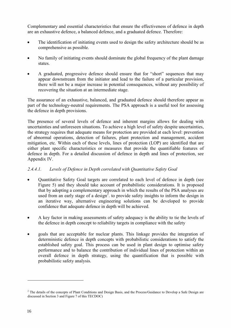
2.4.4.1. Levels of Defence in Depth correlated with Quantitative Safety Goal
• Quantitative Safety Goal targets are correlated to each level of defence in depth (see Figure 5) and they should take account of probabilistic considerations. It is proposed that by adopting a complementary approach in which the results of the PSA analyses are used from an early stage of a design2. to provide safety insights to inform the design in an iterative way, alternative engineering solutions can be developed to provide confidence that adequate defence in depth will be achieved.
• A key factor in making assessments of safety adequacy is the ability to tie the levels of
the defence in depth concept to reliability targets in compliance with the safety • goals that are acceptable for nuclear plants. This linkage provides the integration of
deterministic defence in depth concepts with probabilistic considerations to satisfy the established safety goal. This process can be used in plant design to optimise safety performance and to balance the contribution of individual lines of protection within an overall defence in depth strategy, using the quantification that is possible with probabilistic safety analysis.
2 The details of the concepts of Plant Conditions and Design Basis, and the Process/Guidance to Develop a Safe Design are discussed in Section 3 and Figure 7 of this TECDOC)
16
• The scope and the required level (i.e. domain for the application) for the PSA as the support for the risk informed process has to be defined by considering the probabilistic success criteria (see fig 2). An extension of the PSA methodologies is needed to make them able to assess any reliability target, not only those related with severe plant states as in current PSA. In addition, the use of a single target for core damage will require a level 1 PSA; a target for a source term extending outside the installation will require a level 2 PSA. Uncertainties should also be taken into account since they will affect the implementation of the PSA modelling; this is of particular importance for innovative designs for which appropriate reliability data may not be sufficiently comprehensive. In such cases, a conservative approach should be adopted. Other uncertainties include the modelling method, human reliability performance and uncertainties in the data used.
• To assess the implementation of the defence in depth principle, and the adequacy of the
corresponding levels of defence, probabilistic considerations or probabilistic success criteria can be introduced. To do this, the concept of a quantitative safety goal, outlined above, can be further developed by dividing the allowable risk domain into a series of regions that roughly correspond to the various plant conditions, i.e., normal operations, anticipated operational occurrences (or abnormal operation), accident conditions and severe plant conditions. The response to each plant condition can then be associated with a corresponding level of defence in depth.
UNACCEPTABLE DOMAIN
F
C
AOO
AC
SPC
Events managed by
Lev 2 of D.I.D
10-2
10-6
10-7
Initiating Events are caused by Failures of the Level 1 of D.I.D
Events managed by
Lev 4 of D.I.D
Events managed by Lev 3 of D.I.D
Figure 5. Quantitative Safety Goals & Correlation of Levels of Defence.
Figure 5 also shows the levels of defence in depth that approximately apply in each region. The ranges of frequencies are derived from the definitions of AOO, AC and SPC and are consistent with those used in designs of modern water cooled reactors from which it is shown that:
17
• Normal operational occurrences are accommodated only within the first level of defence in depth and result in no consequences, as the aim of this level is to prevent deviations from normal operation and to prevent system failures.
• The second level of defence in depth assures, by detecting and intercepting deviations from normal operational states, that the consequences of events above a frequency of 10-2/yr, i.e., anticipated operational occurrences (AOOs), are within the success criteria of this second level of defence.
• Similarly, the purpose of level 3 of defence in depth is to ensure that for plant conditions which have not been intercepted by the preceding levels of defence, the consequences of such events (accident sequences) that fall into the accident condition (AC) range, i.e., frequencies between10-2 and 10-6/yr, are within the success criteria of the third level of defence. Note that for a particular accident sequence, the successful limitation of consequences can have been accomplished with level 3 alone, a combination of level 2 and 3, or even with level 2 alone.
• In the same manner, level 4 of defence in depth provides assurance that the consequences associated with severe plant conditions, i.e., accident sequences with frequencies less than 10-6/yr, are limited to those associated with level 4 success criteria. Again the limitation of consequences may be achieved with any combination of levels 2, 3 and 4.
• Finally, level 5 of defence in depth provides mitigation of consequences for those accidents not successfully mitigated by the previous levels. The ultimate objective is that any credible accident sequence, even considering the failures of lines of protection for the different levels of defence in depth, shall remain under the overall frequency-consequence curve.
• Figure 5, with appropriate values of consequences and frequencies on the axes of the diagram, give a visual representation of the contribution of each level of defence to the overall safety of the plant.
This generalized concept of defence in depth integrates both deterministic (number of levels of defence, independence of the levels) and probabilistic considerations (e.g. equipment reliability, probabilistic targets, etc.) to provide metrics for assessing the adequacy of the design provisions for each level of defence and to check the consistency of implementation. As a complementary method for determining the safety classification of the provisions (systems, structures and components) by means of deterministic criteria, a safety assessment model of all plant safety architecture, without any pre-conceived notion of what is important for safety, should also be used to determine the relevance of the equipment for safety and its safety classification. This model can then also be used to assess the contribution of each provision (system, structure or component) to the overall safety of the plant. Should there be barriers or other provisions that need to be strengthened; the value of the improvement can be directly assessed.
• One of the key issues in deterministic and probabilistic analysis is how to deal with uncertainties such as reliability data, human factors, modelling techniques, scenarios to be considered, etc. Traditional deterministic approaches rely on a balance of prevention and mitigation, with large design margins and the ultimate final barrier being the “containment” to cover very low frequency severe events. By employing a risk informed analysis, the contribution to safety of the design features, and the need for additional features can be assessed more effectively. To deal with uncertainties,
18

especially in the early design stages, sensitivity analyses assessing the performance of key systems can be used to provide a measure of the impact of uncertainties and appropriate design decisions can be made.
• Table 1 below provides example frequency and consequence values mainly based on the European Utility Requirements document for the latest LWRs. A comparable approach is recommended for the technology-neutral development of safety requirements for advanced designs, with the safety goal set at least at the same level of safety.
• The consequence limits associated with the different levels of defence in depth, together with the associated ranges of frequencies of events, also provides a technology-neutral way to define such terms as: design basis, accident conditions, and severe plant conditions.
Table 1. Example of possible plant conditions and consequence values
NOTE 3: Based on the approach of the European Utility Requirements for LWR
Minimal emergency actions beyond defined distance from the plant
No off-site actions beyond defined distance from the plant
None None Off-site Actions
NOTE 2: Doses are derived from IAEA-SS No 115
5 mSv/a (For 1 year period following the accident)
5 mSv/a (For 1 year period following the accident)
5 mSv/a 1 mSv/a (average 5 y)
1 mSv/a (10 μ Sv/a –target)
Doses to the public
NOTE 1: Doses for NO, AOO, AC are derived from IAEA-SS No 115
500 mSv (limit) (This value derived from Finnish regulation)
50mSv/a (Could be exceeded for rear recovery events)
50 mSv/a 20 mSv/a (average 5 y) (5 mSv/a target)
50 mSv/a ALARA (5 mSv/a target)
Doses to Operators
Severe plant conditions* (SSPC)
Accident conditions(AC)
Anticipated Operational Occurrences (AOO)
Normal Operations (NO)
Plant conditions Consequences
* Severe challenge to the Fission Products Confinement Function
Design Basis Conditions
2.4.4.2. Lines of Protection (LOP)
In order to guide, evaluate or compare the implementation of defence in depth for different reactor technologies, a common approach is suggested that can be used to integrate the unique characteristics of a specific type of reactor with the required “defences” necessary to provide an adequate response to the potential internal and external challenges and consequences of failures.
To implement this, it is useful to introduce the concept of a line of protection (LOP). Note that the Line of Protection concept is similar to the concept of safety groups in NS-R-1 [3], but more general, i.e. LOP identifies a safety group for each PIE, and there is a LOP identified for each safety function and for each level of Defence in Depth. A line of protection is an effective defence against a given mechanism or event that has the potential to impair a fundamental safety function. This term is used for any set of inherent characteristics,
19

equipment, system (active or passive), etc., that is part of the plant safety architecture, the objective of which is to accomplish the mission needed to achieve a given safety function. For a given event, and against a given safety function, the LOPs provide the practical means of successfully achieving the objectives of the individual levels of defence (refer to figure 6).
For a given plant condition (a PIE which occurs when the facility is in a given initial state) and within a level of the defence, the implemented LOP will either:
• prevent the abnormal condition from deteriorating further, and/or
• return the plant from the abnormal condition to a controlled safe condition and maintain it in a safe state.
Therefore, these LOPs cope with the challenges so as to allow the achievement of the required safety functions, thus meeting the objective of the level of defence.
The adequacy of a line of protection is determined by its performance in terms of capacity, timing, etc., and its reliability and the associated uncertainties. The design of the LOPs should take into account the plant operational requirements, e.g., operating limits, surveillance and maintenance requirements.
The methodology presented enables an assessment of the detailed design performance of the complete plant, based on:
• a deterministic approach that describes the required physical performance, and
• a probabilistic safety assessment model which explicitly accounts for reliabilities of components and addresses scenarios ranked by likelihood of occurrence.
The product of this process is the identification of the LOP and the determination of their characteristics, in terms of their physical performance, their reliability, and independence. Physical performance considerations will generate requirements in terms of technical design specifications, while the assumed reliability will generate requirements in terms of quality.
3. A METHODOLOGY TO GENERATE TECHNOLOGY-NEUTRAL SAFETY
REQUIREMENTS AND DESIGN
This section describes a methodology to generate technology-neutral safety requirements, which determine the recommendations for the design of the power plant. This process is iterative. The Objectives Provisions Tree is a systematic review of the implementation of the defence in depth. The iterative design process described is the implementation of the Objectives Provisions Tree. This section of the document addresses areas (4), (5) and (6) of Figure 1 in more detail.
3.1. Plant Conditions and Design Basis
The key objective in defining the design basis is to establish a set of representative plant conditions, which are then used to design and implement the safety architecture. The designer of an innovative reactor is likely to start with a basic design that consists only of those features sufficient to allow the realization of the underlying concepts on which the innovative reactor is based. These features are already likely to include some inherent characteristics that
20
also contribute to the safety performance of the concept. One of the following steps in the design will directly address the establishment of the desired level of safety. A set of plant conditions and design basis can be derived from the listing of PIEs (see Appendix I) for the purpose of setting the boundary conditions according to which the LOP (structures, systems and components important to safety and inherent features) are to be designed.
An initial set of plant conditions can be selected from all plausible plant states by identifying all those accident sequences that fall within the established frequency ranges. From this set, bounding groups of sequences may be selected which envelope analogous plant conditions in terms of consequences, so that the individual sequences need not be explicitly addressed.
The Design Basis includes the following Design Basis Conditions (DBC): normal operation, anticipated operational occurrences (AOO), accident conditions (AC) and severe plant conditions (SPC). The last three of these conditions, i.e., the abnormal conditions of AOO, AC, and SPC are of interest for accident analysis.
An initial probabilistic safety analysis (PSA) should be undertaken for each plant condition at this stage to produce preliminary numerical estimates of the potential safety performance of the design, and to indicate the importance to safety of the proposed safety provisions. To carry out such an analysis, the design of the plant and the engineering intentions need to be known in some detail. 3.1.1 Normal Operating Conditions
A plant is designed to be operated safely for a defined operating range including the shutdown state. General means of protection is achieved through conservative design, quality assurance and a positive safety culture.
3.1.2 Abnormal Operating Conditions
All abnormal conditions (AOO, and AC) considered in the design basis are characterised by a postulated initiating event (PIE), which occurs when the facility is in a given initial state. All
the required characteristics of the plant (full power, shutdown, etc.) should be defined, and the acceptance criteria for each abnormal condition set. The plant response should be analysed to verify that for each abnormal condition, the relevant acceptance criteria are achieved, and the outcomes recorded. Under the logic of the levels of defence in depth, entering into an abnormal condition represents the failure of the first level of defence in depth. Each PIE is classified by category, based on its estimated frequency of occurrence. By analogy with the PIEs, a similar categorisation could be applied to the Plant Conditions and Design Basis. The plant safety assessment is structured through the analysis of these Plant Conditions and Design Basis.
3.1.3 Anticipated Operational Occurrences
AOO are deviations from the normal operation of the plant, which in view of appropriate design provisions does not cause any significant damage to systems and components important to safety or lead to accident conditions.
21

3.1.4 Accident Conditions
AC are deviations from normal operation of the plant or degraded situations from AOO resulting in significant damage to some structures, systems or components, while maintaining sufficient capability to avoid release of large amount of radioactive material outside the plant.
3.1.5 Severe Plant Conditions
Certain very low probability plant states that are beyond AOO and accident conditions and which may arise owing to multiple failures of safety systems leading to significant plant degradation may jeopardize the integrity of many or all the barriers to the release of radioactive material. These event sequences, in the frequency range of 10-6 to 10-7, are also considered in the design and are called Severe Plant Conditions (SPCs) and generally include multiple failure sequences that fall within that range of probability. Consideration is given to these severe plant condition sequences, using a combination of engineering judgement and probabilistic methods, to determine those sequences for which reasonably practicable preventive or mitigative measures can be identified. Appropriate design rules and criteria are set for SPCs, in general different from those for AOO, and accidents (DBC). Because these sequences are very low probability events, acceptable countermeasures need not involve the application of conservative engineering practices used in setting and evaluating design basis accidents, but rather should be based upon realistic or best estimate assumptions, methods and analytical criteria. Consideration is given to the full design capabilities of the plant, including the possible use of some systems (i.e. safety and non-safety systems) beyond their originally intended function and anticipated operational states, and the use of additional temporary systems, to return the plant to a controlled state and/or to mitigate the consequences of a severe accident, provided that it can be shown that the systems are able to function in the environmental conditions to be expected. The results of the PSA should be used to identify potential systems that may be required to operate under such extreme conditions.
3.1.6 Accident Management
Accident management procedures are established, taking into account representative and enveloping severe plant condition scenarios.
3.2 Applying Objectives Provisions Tree Method
The method described here of the Objectives Provisions Tree is a systematic “critical review” of the implementation of the Defence in Depth.
Once an initial set of plant conditions and design basis is determined and the magnitude of the challenges they represent established, the designer can then systematically determine the inherent features, equipment, and procedures (i.e., the provisions) needed to meet the challenges. These provisions can then be grouped into the lines of protection required to achieve each level of defence. The provisions and their implementation may, in turn, generate complementary conditions that have to be addressed through an iterative process; their failure has to be considered as a complementary potential challenge. The method of the objective-provisions tree, originally developed within IAEA TECDOC 1366 [2], is recommended here to achieve this purpose. The approach focuses on each level of defence by identifying the safety functions that need to be performed; the objectives to be achieved by that level of defence; the challenges posed by the design to maintain that function; the mechanisms that will lead to the failure of the function; and the provisions that are in place to deal with the failure mechanisms. The method represents one way to systematically address the
22

implementation of defence in depth. It also identifies the required provision for, and the design reliability targets for, the corresponding LOPs. The logical framework of the objective-provision tree is shown diagrammatically in Figure 6.
Objectives
Safety Function
Level ofDefence
To be achieved (e.g. prevention of deviation from Normal Operation
To be performed successfully(e.g. heat removal)
ChallengeChallenge To cope with (e.g. disruption of heat transfer path)
MechanismMechanism To be prevented or controlled(e.g. loss of coolant)
Provision
Provision To be implemented to prevent and/or control mechanisms (e.g. conservative design, seismic design)
Level of Defence in depth (e.g. Level 1)
Line of Protection (LOP): Set of provisions that jointly ensure the prevention or control of the
mechanism
Mechanism
ProvisionProvision
Provision
Provision
Figure 6. The Objectives Provisions Tree Approach.
The development of this tree provides the objectives that are technology-neutral; the guidelines to consider for the missions that must be achieved; and finally identification of the acceptable provisions (i.e. the design options) available to the designer and the required technical design specifications. The concept of the objectives provisions tree is technology-neutral while the application of the tree, at least from the challenge mechanisms down, will be technology-specific.
As an additional check, beyond the use of the objectives provisions tree, the designer may want to compare the design with relevant information such as the current criteria for safety for light water reactors. This may aid the designer in determining whether any key areas have been missed and can point to the unique features of the new technology that need to be considered in the establishment of safety requirements.
3.3 Design Process for Innovative Reactor Designs
The correct implementation of defence in depth requires that the design follow a process, which is systematic, logical and auditable. A scheme to achieve such a process is presented and described below (Fig.7). This is the implementation of the Objectives Provisions Tree.
23

Figure 7. Process to ensure that adequate defence in depth is achieved.
24
Stage (1) - Review of Levels of Defence
Once an initial design has been developed as outlined in the previous sections, the adequacy of the defence in depth measures can be systematically reviewed following the process indicated in figure 7 (i.e. the implementation of the objective provision tree). The design to be reviewed is the basic reactor design that has been enhanced with the features needed to meet the challenges posed by the DBCs. Provisions that will address the mechanisms of the challenges have been identified and organized into LOPs. Further refining and completing the design so it meets the deterministic and reliability targets of the overall safety goal, as well as determining what lines of protection are needed for each level of defence in order to meet the safety goal, is necessarily an iterative process. The PIE identification, the selection of sequences to be addressed, and sequences to be excluded by design (or practically excluded), is an essential stage of this process. The means of terminating the corresponding sequences should also be specified and all the safe states for the plant defined.
Stage (2) - Risk Assessment
With the preliminary LOP architecture established; there will be sufficient information to allow the designer to perform an initial safety assessment. The safety assessment considers all relevant postulated initiating events (PIE) for the range of plant operating states required for the reactor concept being considered, e.g., full power/partial power operation, maintenance during operation, at power refuelling, shutdown conditions, etc. Appropriate uncertainty and sensitivity analyses should be conducted as part of the PSA process during this stage. Adequate success criteria should be used for the assessment of each level of defence in depth, so that consistency with the Quantitative Safety Goal is maintained.
The level of PSA needed depends on the consequence metrics chosen for the safety goal representation. If the metrics are health effects, a Level 1, 2 and 3 PSA is necessary. If other metrics are available for a particular reactor concept, which can be used as surrogates for the health effects, it may only be necessary to produce a Level 2 PSA analysis.
Stage (3) - Identify Systems, Barriers, Phenomena, Actions Required to Provide Defence in Depth From the results of the PSA the designer should investigate how well the quantitative goals for each level of defence have been met, as well as assessing the design against some qualitative principles that apply to defence in depth (e.g. balanced & graduated defence). For each level of defence the assessments indicated in Stages (4a) and (4b) are carried out.
Stages (4a) [and (5)] - Review of LOP Reliability
The first part of the assessment is carried out by using the PSA results to determine if the LOPs have the required reliability to satisfy the frequency goals and associated consequences for the level of defence being examined. The demonstration of compliance with the reliability targets needs to account for uncertainties in the estimates of the reliabilities of systems, structures, components and operator actions used in the PSA. This inclusion of the uncertainties capable of being modelled in the safety assessment is an essential step. It is also possible that the risk assessment and this review will identify areas where success probabilities have been significantly exceeded. In such cases the designer may consider modifying and/or deleting existing proposed LOPs. If any modifications have been made to the LOPs, another assessment of their reliability is then performed with an appropriately
25
revised PSA. Once adequate reliability has been established the process proceeds to Stage (4b).
Stages (4b) [and (5)] - Review of Defence in Depth Principles
In this part of the assessment the designer will verify that the fundamental principles of defence in depth have been met, for example: that there is a reasonable balance in the proposed methods of delivery of defence in depth; that there is no excessive reliance on a single system, unproven phenomena or on administrative processes; that there are no unrealistic operator actions required, etc.
Stage 5 – Review and Modify the Design
In this stage, the outputs first from Stage 4a and then Stage 4b are reviewed to confirm whether the reliability targets and defence in depth measures have been met. If the reliability targets for the LOP have not been met the designer will need to modify existing LOPs and/or add new ones, thus enhancing the defence in depth and its reliability. Where the defence in depth principles have not been satisfactorily achieved the designer will need to review the design and modify it until the principles can be demonstrated as having been met. If modifications are made, the process has to return to Stage (3), to verify that the changes have not impacted on the reliability requirements. When the assessments of Stages (4a) and (4b) have produced satisfactory results, the process can proceed to Stage (6).
Uncertainties in plant behaviour prediction should also be taken into account to the extent possible to evaluate the final state of each sequence with regard to the Quantitative Safety Goal.
Stage (6) - Accounting for Uncertainty
Proper consideration of uncertainty is an essential part of the safety assessment. This is particularly important for innovative systems where the state of knowledge is not as advanced as for existing plants. At this stage an overall assessment of the level of defence being examined and its associated uncertainty is carried out to determine whether the identified uncertainties are adequately addressed, and the level of defence is adequately implemented. An appropriate method for dealing with uncertainties is the use of sensitivity analyses for uncertain parameters to determine their relative importance in the overall safety architecture. Any shortfalls in dealing with uncertainties will require further analysis and assessment with a return to Stage (3).
Stage (7) - Confirmation of Design Provisions
The whole process described above implicitly integrates the risk informed approach into the design. When all the levels of defence have been examined in the above manner, the final stage in this iterative process is a check to confirm that the design is exhaustive, balanced, and graduated, and meets the safety goals. It will also confirm that no particular level of defence has been degraded and that the overall treatment of uncertainties is acceptable. If any of these elements are not adequately demonstrated then the designer will need to revisit the initial design concept (Stage 1). Once the requirements of stage (7) have been met the designer will then be in a position to finalise the design (stage 8).
26

Stage (8) - Finalisation of the Design
When all checks and assessments have been satisfactorily completed, the design can be finalised with appropriate monitoring and feedback provisions. As the design develops in greater detail further information may become available which challenges the assumptions, analyses or uncertainties used in the safety assessment. This process requires the designer to revisit the safety assessment, either after a significant change or periodically.
As part of this overall process the designer should also assess scenarios that are beyond the AOO, and accident conditions. The designer can use PSA methods to evaluate whether the likelihood of postulated events/sequences should be considered in Level 4 of the defence in depth, i.e. severe plant conditions, or if they can be excluded.
As the above described process indicates, the development of acceptable designs for innovative reactors will be iterative, initially by the designer and ultimately with the regulator. As the design develops from conceptual to final, the designer will perform PSAs in greater detail during which a more robust design emerges.
At each stage of the iterative process, which has been described in the preceding parts of this Section, the original design concept should be modified to reflect the developments in the associated studies, and the status of the proposed plant should be reviewed, updated and fully documented to provide the safety justification. The basis for design should therefore:
• Specify the necessary capabilities of the plant to cope with the range of normal and abnormal conditions identified from the deterministic and probabilistic analyses, and which satisfy the safety goal and the prescribed radiological protection requirements.
• Include the specification for normal operation, plant states created by the PIEs, including accidents and severe plant conditions, and the measures to ensure defence in depth is achieved at all levels consistent with the safety goal, and taking account of risk dominant accident sequences developed through the PSA.
• Specify the safety classification of items important to safety, as derived from a balanced consideration of the probabilistic and deterministic approaches.
• Determine the activation criteria (set points) for each automatic and manual protective feature.
• Justify important assumptions and, of particular importance to innovative designs, the particular methods of analysis, and evidence that the claims for novel features have been demonstrated by means of research, controlled experiments, a demonstration plant, or a combination of these.
• Identify novel features of the design for which extensive component testing is required in order to provide confidence that the reliability targets will be achieved.
• Specify the means by which the lines of protection will continue to be maintained at the required reliability for the lifetime of the plant.
• Specify the operating limits and conditions for the plant.
27


APPENDIX I.
SAMPLE PROPOSAL OF TECHNOLOGY-NEUTRAL REQUIREMENTS (BASED ON CRITICAL REVIEW OF NS-R-1)
I.1. REQUIREMENTS FOR MANAGEMENT OF SAFETY
RESPONSIBILITIES IN MANAGEMENT
I.1.1. The operating organization has overall responsibility for safety. However, all organizations engaged in activities important to safety have a responsibility to ensure that safety matters are given the highest priority. The design organization shall ensure that the installation is designed to meet the requirements of the operating organization, including any standardized utility requirements; that it takes account of the current state of art for safety; that it is in accordance with the design specifications and safety analysis; that it satisfies national regulatory requirements, that it fulfils the requirements of an effective quality assurance programme; and that the safety of any design change is properly considered. Thus, the design organization shall:
(1) implement safety policies established by the operating organization;
(2) have a clear division of responsibilities with corresponding lines of authority and communication;
(3) ensure that it has sufficient technically qualified and appropriately trained staff at all levels;
(4) establish clear interfaces between the groups engaged in different parts of the design, and between designers, utilities, suppliers, constructors and contractors as appropriate;
(5) develop and strictly adhere to sound procedures;
(6) review, monitor and audit all safety related design matters on a regular basis; and
(7) ensure that a safety culture is maintained.
MANAGEMENT OF DESIGN
I.1.2. The design management for a nuclear power plant shall ensure that the structures, systems (SSC) and components important to safety have the appropriate characteristics, specifications and material composition so that the safety functions can be performed and the plant can operate safely with the necessary reliability for the full duration of its design life, with accident prevention and protection of site personnel, the public and the environment as prime objectives.
I.1.3. The design management shall ensure that the requirements of the operating organization are met and that due account is taken of the human capabilities and limitations of personnel. The design organization shall supply adequate safety design information to ensure safe operation and maintenance of the plant and to allow subsequent plant modifications to be made, and recommended practices for incorporation into the plant administrative and operational procedures (i.e. operational limits and conditions).
29
I.1.4. The design management shall ensure that the design is developed in accordance with the iterative process outlined in Section 4, taking into account the results of the deterministic and probabilistic safety analyses, and by applying the principles of the defence in depth, it shall be ensured that due consideration has been given to the prevention of accidents and mitigation of their consequences.
I.1.5. The design management shall ensure that the generation of radioactive waste is kept to the minimum practicable, in terms of activity, volume and radio toxicity, by appropriate design measures and operational and decommissioning practices. PROVEN ENGINEERING PRACTICES
I.1.6. Wherever possible, structures, systems and components important to safety (i.e. lines of protection) shall be designed according to the latest or currently applicable approved standards; shall be of a design proven in previous equivalent applications; and shall be selected to be consistent with the plant reliability goals necessary for safety. Where codes and standards are used as design rules, they shall be identified and evaluated to determine their applicability, adequacy and sufficiency, and shall be supplemented or modified as necessary to ensure that the final quality is commensurate with the necessary safety function.
I.1.7. Where an innovative, or unproven design or feature is introduced or there is a departure from an established engineering practice, safety shall be demonstrated to be adequate by appropriate supporting research programme, or by examination of operational experience from other relevant applications. The development shall also be adequately tested before being brought into service and monitored in service, to verify that the expected behaviour is achieved.
I.1.8. In the selection of equipment, consideration shall be given to both spurious operation and unsafe failure modes (e.g. failure to trip when necessary). Where failure of a structure, system or component has to be expected and accommodated by the design, preference shall be given to equipment that exhibits fail safe behaviour as well as a predictable and revealed mode of failure and facilitates repair or replacement.
OPERATIONAL EXPERIENCE AND SAFETY RESEARCH
I.1.9. An innovative design shall be supported by the results of relevant research programmes, which shall provide adequate evidence that the safety claims to be made are justifiable. The design shall also take due account of relevant operational experience that has been gained during the research and development programme and in other operating plants.
SAFETY ASSESSMENT
I.1.10. A comprehensive safety assessment shall be carried out to confirm that the design as delivered for fabrication, construction and as built meets the safety requirements set out at the beginning of the design process.
I.1.11. The safety assessment shall be part of the design process (see section 4), with iteration between the design, the PSA and all confirmatory analytical activities, increasing in the scope and level of detail as the design programme progresses.
30

I.1.12. The basis for the safety assessment shall be data derived from the safety analysis, previous operational experience where appropriate, the results of supporting research into the innovative features of the design, and proven engineering practice.
INDEPENDENT VERIFICATION OF THE SAFETY ASSESSMENT
I.1.13. The operating organization shall ensure that an independent verification of the safety assessment is performed by individuals or groups separate from those carrying out the design, before the design is submitted to the regulatory body.
QUALITY ASSURANCE MANAGEMENT SYSTEM
I.1.14. A quality assurance programme that describes the overall arrangements for the management, performance and assessment of the plant design shall be prepared and implemented. This programme shall be supported by more detailed plans for each structure, system and component so that the quality of the design is ensured at all times.
I.1.15. Design, including subsequent changes or safety improvements, shall be carried out in accordance with established procedures that call on appropriate engineering codes and standards, and shall incorporate applicable requirements and design bases. Design interfaces shall be identified and controlled.
I.1.16. The adequacy of design, including design tools and design inputs and outputs, shall be verified or validated by individuals or groups separate from those who originally performed the work. Verification, validation and approval shall be completed before implementation of the detailed design.
I.2. TECHNOLOGY-NEUTRAL PRINCIPAL TECHNICAL REQUIREMENTS
SAFETY FUNCTIONS
I.2.1. To ensure safety, the following fundamental safety functions shall be performed in operational states, in and following a design basis accident and, to the extent practicable, in and after the occurrence of plant states considered that are beyond those of the design basis accidents (severe plant conditions):
(1) control of the reactivity;
(2) removal of heat from the core; and
(3) confinement of radioactive materials and control of operational discharges, as well as limitation of accidental releases.
I.2.2. A systematic approach shall be followed to identify the lines of protection (characteristics, structures, systems and components) that are necessary to fulfil the safety functions while addressing the possible challenges and the corresponding mechanisms (Note: section 3.2 of the main part of this TecDoc which describes the Objective Provision Tree methodology provides a suitable logic to be followed.)
31

REQUIREMENTS FOR DEFENCE IN DEPTH
I.2.3. In the design process, defence in depth shall be incorporated as described in Section 4. Deterministic and probabilistic acceptance criteria shall be defined for each level of defence in depth in accordance with the safety goal. The provisions implemented for each level of defence in depth shall be such that the acceptance criteria are met for each level.
The design therefore:
(1) shall be conservative, and the construction shall be of high quality, so as to provide confidence that plant failures and deviations from normal operations are minimized and accidents prevented;
(2) shall provide for control of the plant behaviour during and following a PIE, using inherent and engineered features, i.e. non-operational transients shall be minimized or excluded by design to the extent possible;
(3) shall provide for supplementing control of the plant, by the use of automatic activation of safety or safety related systems (lines of protection) in order to minimize operator actions in the early phase of PIEs, and by operator actions;
(4) shall provide for equipment and procedures (additional lines of protection) to control the course and limit the consequences of accidents as far as practicable; and
(5) shall provide multiple means (lines of protection) for ensuring that each of the fundamental safety functions, i.e. control of the reactivity, heat removal and the confinement of radioactive materials is performed, thereby ensuring the mitigation of the consequences of any PIEs as required by the specific plant design, and based on the probabilistic and deterministic analyses.
I.2.4. To ensure that the overall safety concept of defence in depth is maintained, the design shall be such as to prevent as far as practicable:
(1) challenges to the lines of protection;
(2) failure of a level of defence when challenged;
(3) failure of a level of defence as a consequence of failure of another level of defence
I.2.5. The design shall be such that it provides adequate means to maintain the plant in a normal operational state; to ensure the proper short term response immediately following a PIE; and to facilitate the management of the plant in and following any anticipated operational occurrence, accident, and any severe plant conditions that are considered in the design basis.
I.2.6. The design shall be such that the first, or at most the second, level of defence, the implemented lines of protection are capable of preventing escalation to accident conditions
for all but the most improbable PIEs that lead to severe plant conditions. The design shall be such that for all the levels of defence, the corresponding lines of protection are capable of preventing escalation to more severe conditions.
32
I.2.7. The design shall take into account the fact that the existence of multiple levels of defence is not a sufficient basis for continued power operation in the absence or deterioration of one level of defence. All levels of defence shall remain available in a way compatible with the required safety level (adequate performance and reliability), i.e. some relaxation may be specified for the various operational modes during which the requirement for the satisfactory achievement of a safety functions may be modified.
ACCIDENT PREVENTION AND PLANT SAFETY CHARACTERISTICS
I.2.8. The plant design shall be such that its sensitivity to PIEs is minimized. The expected plant response to any PIE shall be those of the following that can reasonably be achieved (in order of importance):
(1) a PIE produces no significant safety related effect or produces only a change in the plant towards a safe condition by inherent characteristics provided it is demonstrated that the assumed reliability and effectiveness of such characteristics is maintained for the entire design lifetime; or
(2) following a PIE, the plant is rendered safe by passive safety features or by the action of safety systems that are continuously operating in the state necessary to control the PIE; or
(3) following a PIE, the plant is rendered safe by the action of safety systems that need to be brought into service in response to the PIE; or
(4) following a PIE, the plant is rendered safe by specified procedural actions.
RADIATION PROTECTION AND ACCEPTANCE CRITERIA
I.2.9. A limited number of sets of radiological acceptance criteria, which are consistent with the safety objectives shall be defined for normal operation, anticipated operational occurrences, accidents and severe plant conditions. The radiological acceptance criteria for these categories shall, as a minimum level of safety, satisfy the requirements of the regulatory body, and meet the safety goal standard. I.2.10. In order to achieve the three safety objectives expressed in terms of radiological consequences in the design of a nuclear installation, all actual and potential sources of radiation shall be identified and properly considered, and provision shall be made to ensure that sources are kept under strict technical and administrative control.
I.2.11. Measures shall be provided to ensure that the radiation protection and technical safety objectives are achieved, and that radiation doses to the public and to site personnel in all operational states, including maintenance and decommissioning, do not exceed prescribed limits and are as low as reasonably achievable.
I.2.12. The design shall have as an objective the prevention or, if this fails, the mitigation of radiation exposures resulting from events included in the design basis. Design provisions shall be made to ensure that potential radiation doses to the public and the site personnel do not exceed acceptable limits and are as low as reasonably achievable.
33

I.2.13. Plant states that could potentially result in high radiation doses or radioactive releases shall be restricted to a very low likelihood of occurrence, and it shall be ensured that the potential radiological consequences of plant states with a significant likelihood of occurrence shall be only minor. Radiological acceptance criteria for the design of a nuclear power plant shall be specified on the basis of these requirements. The radiological acceptance criteria shall be based on a safety goal derived from the acceptable site boundary dose and frequency of occurrence.
I.3. TECHNOLOGY-NEUTRAL REQUIREMENTS FOR PLANT DESIGN DESIGN BASIS
I.3.1. The design basis shall specify the necessary capabilities of the plant to cope with a specified range of normal and abnormal conditions within the defined radiological protection requirements. The design basis shall include the specification for normal operation, plant states created by the PIEs, the safety classification, important assumptions and, in some cases, the particular methods of analysis.
I.3.2. All events and sequences with a frequency of occurrence higher than 10-7 per reactor year shall be considered in the design basis.
I.3.3. Conservative design measures shall be applied and sound engineering practices shall be followed for the design of the lines of protection (structures, systems and components) so as to provide a high degree of assurance that no significant damage will occur to the reactor core and that radiation doses will remain within prescribed limits and will be ALARA.
I.3.4. The assumptions, calculational methods and margins used for the design shall be commensurate with the importance to safety of the SSC and consistent with its safety classification.
I.3.5. The plant conditions (PIEs which occur when the plant is in a given state) shall be identified and grouped into a limited number of categories according to their probability of occurrence. The categories typically cover normal operation, anticipated operational occurrences, design basis accidents and severe plant conditions. All these categories shall be considered for the design of the provisions while recognizing the possibility for specific rules and methods, e.g. to take into account uncertainties and margins. Acceptance criteria shall be assigned to each category that take account of the requirement that frequent PIEs shall have only minor or no radiological consequences, and that events that may result in severe consequences shall be of very low probability
Postulated Initiating Events (PIE)
I.3.6. In the design of the plant, it shall be recognized that challenges to all levels of defence in depth may occur and design measures (lines of protection) shall be provided to ensure that the necessary safety functions are accomplished with the required reliability and the safety goal can be met. These challenges stem from the PIEs, which are selected on the basis of probabilistic or deterministic techniques or a combination of the two. In the analysis of PIEs that are technology-specific, particular care shall be taken to evaluate the design of the plant to determine all possible initiating events.
34

Internal Events
I.3.7. An analysis of the PIEs shall be made to establish all those internal events which may affect the safety of the plant. These events may include equipment failures or maloperation.
Fires and explosions
I.3.8. Structures, systems and components important to safety shall be designed and located so as to minimize, consistent with other safety requirements, the probabilities and effects of fires and explosions caused by external or internal events. The capability for shutdown, residual heat removal, confinement of radioactive material and monitoring of the state of the plant shall be maintained. These requirements shall be achieved by suitable incorporation of redundant parts, diverse systems, physical separation and design for fail-safe operation such that the following objectives are achieved:
(1) to prevent fires from starting;
(2) to detect and extinguish quickly those fires which do start, thus limiting the damage;
(3) to prevent the spread of those fires which have not been extinguished, thus minimizing their effects on essential plant functions.
I.3.9. In order to achieve the requirements of para 6.10, a fire hazards analysis shall be carried out of the plant, utilizing a combination of established deterministic methods and a fire PSA, to confirm the necessary rating of the fire barriers, and the necessary capability of the fire detection and fire fighting systems which are to be provided.
I.3.10. Fire fighting systems shall be automatically initiated where necessary, and systems shall be designed and located so as to ensure that their rupture or spurious or inadvertent operation does not significantly impair the capability of structures, systems and components important to safety, and does not simultaneously affect redundant safety groups, thereby rendering ineffective the fire protection measures. The fire PSA shall confirm that such challenges are identified, addressed, and quantified.
I.3.11 Non-combustible or fire retardant and heat resistant materials shall be used wherever practicable throughout the plant, particularly in locations such as the confinement and the control room.
Other internal hazards
I.3.12. The potential for internal hazards such as flooding, missile generation, pipe whip, jet impact, or release of fluids or gases from failed systems or from other installations on the site shall be taken into account in the design of the plant. Appropriate preventive and mitigatory measures shall be provided to ensure that nuclear safety is not compromised. Some external events may initiate internal fires or floods and may lead to the generation of missiles. Such interaction of external and internal events shall also be considered in the design, where appropriate. The basis of such an analysis shall be an internal hazards analysis using risk assessment tools.
I.3.13. If two systems that are operating at different pressures are interconnected, either the systems shall both be designed to withstand the higher pressure, or provision shall be made to
35

preclude the design pressure of the system operating at the lower pressure from being exceeded.
External Events
I.3.14. The design basis natural and human induced external events shall be determined for the proposed combination of site and plant. All those events with which significant radiological risk may be associated shall be considered. A combination of deterministic and probabilistic methods shall be used to select a subset of external events which the plant is designed to withstand, and from which the design bases are determined.
I.3.15. Natural external events which shall be considered include those which have been identified in site characterization, such as earthquakes, floods, high winds, tornadoes, tsunami (tidal waves) and extreme meteorological conditions. Human induced external events that shall be considered include those that have been identified in site characterization and for which design bases have been derived. The list of these events shall be reassessed for completeness at an early stage of the design process.
I.3.16. SSCs that are part of the provisions for the first level of defence in depth and the failure of which could lead to accident conditions or severe plant conditions shall be designed for the most serious set of external events determined for the site.
Site Related Characteristics
I.3.17. In determining the design basis of a nuclear power plant, various interactions between the plant and the environment, including such factors as population, meteorology, hydrology, geology and seismology, shall be taken into account. The availability of off-site services upon which the safety of the plant and protection of the public may depend, such as the electricity supply and fire fighting services, shall also be taken into account.
I.3.18. Projects for nuclear power plants to be sited in tropical, polar, arid or volcanic areas shall be assessed with a view to identifying special design features which may be necessary as a result of the characteristics of the site. Combinations of Events
I.3.19. Where combinations of randomly occurring individual events could credibly lead to anticipated operational occurrences, accident conditions, or severe plant conditions they shall be considered in the design. Certain events may be the consequences of other events, such as a flood following an earthquake. Such consequential effects shall be considered to be part of the original PIE.
Design Standards
I.3.20. The engineering design standards for structures, systems and components shall be specified and shall comply with the appropriate accepted national standard engineering practices (see para. 4.6), or those standards or practices already used internationally or established in another country, and whose use is applicable and also accepted by the national regulatory body.
36

Design Limits
I.3.21. A set of design limits consistent with the key physical parameters for each structure, system or component shall be specified for each plant state of the design basis (operational states, accidents conditions and severe plant conditions). These parameters shall ensure that the safety goal as expressed in terms of radiological consequences will be achieved. SAFETY CLASSIFICATION I.3.22. All structures, systems and components, including software for instrumentation and control (I&C), that are items important to safety shall be first identified and then classified on the basis of their function and significance with regard to safety. They shall be designed, constructed and maintained such that their quality and reliability is commensurate with this classification.
I.3.23. The method for classifying the safety significance of a structure, system or component shall be based on the application of defence in depth and make use of the results of a risk informed process in which the deterministic safety analysis is complemented by insights from the plant probabilistic safety analysis and supported by engineering judgement that explicitly establishes the importance of that particular component, system or structure to the safety of the plant. This analysis shall take the following factors into account:
(1) the safety function(s) to be performed by the item;
(2) the consequences of failure to perform their function;
(3) the probability that the item will be called upon to perform a safety function
(4) the time following a PIE at which, or the period throughout which, it will be called upon to operate, and
(5) the level or levels of defence in depth to which the structure, system or component belong.
I.3.24. SSCs that are part of the provisions for the first level of defence in depth the failure of which could lead to accident conditions or severe plant conditions shall be assigned to the highest safety class.
I.3.25. Appropriately designed interfaces shall be provided between structures, systems and components of different classes to ensure that any failure in a system classified in a lower class will not propagate to a system classified in a higher class.
Operational States
I.3.26. The plant shall be designed to operate safely within a defined range of parameters (for example, of pressure, temperature, power), and a minimum set of specified support features for safety systems (for example, emergency electrical power supply) shall be assumed to be available. The design shall be such that the response of the plant to a wide range of anticipated operational occurrences will allow safe operation or shutdown, if necessary, without the necessity of invoking provisions beyond the first, or at the most the second, level of defence in depth.
37

I.3.27. The potential for accidents to occur during maintenance in operation, in low power and shutdown states, such as startup, refuelling and maintenance, when the availability of safety systems may be reduced, shall be addressed in the design, and appropriate limitations on the unavailability of safety systems shall be specified.
I.3.28. The design process shall establish a set of requirements and limitations for safe operation, including:
(1) safety system settings;
(2) control system and procedural constraints on process variables and other important parameters;
(3) requirements for maintenance, testing and inspection of the plant to ensure that structures, systems and components function as intended in the design, with the ALARA principle taken into consideration; and
(4) clearly defined operational configurations, including operational restrictions in the event of safety system outages.
I.3.29. These requirements and limitations shall be a basis for the establishment of operational limits and conditions under which the operating organization will be authorized to operate the plant and that will not exceed the limits of the second level of defence in depth.
Accident Conditions
I.3.30. A set of design basis accidents conditions shall be derived using a combination of deterministic and probabilistic methods applicable to the particular technology, for the purpose of setting the boundary conditions according to which the structures, systems and components of the provisions of level three of defence in depth shall be designed.
I.3.31. Where prompt and reliable action is necessary in response to a PIE, provision shall be made to initiate the necessary actions of safety system automatically, in order to prevent progression to a more severe condition that may threaten the next level of defence. Where prompt action is not necessary, manual initiation of systems or other operator actions may be permitted, provided that the need for the action is revealed in sufficient time and that adequate procedures (such as administrative, operational and emergency procedures) are defined to ensure the reliability of such actions.
I.3.32. The operator actions that may be necessary to diagnose the state of the plant and to put it into a stable long term shutdown condition in a timely manner shall be taken into account and facilitated by the provision of adequate instrumentation to monitor the plant status and controls for manual operation of equipment.
I.3.33. Any equipment necessary in manual response and recovery processes shall be placed at the most suitable location to ensure its ready availability at the time of need and to allow human access for the anticipated environmental conditions.
Severe Plant Conditions
I.3.34. The design basis shall include those severe plant conditions that may result from the failure of the first three levels of defence in depth and that fall in the range of frequency 10-6 –10-7 per reactor-year. If these conditions have the potential for unacceptable core degradation or release of radioactive materials they shall be eliminated or practically eliminated by design,
38
and it shall be shown that the occurrence is so rare that it falls within the residual risk area of the frequency/consequences curve (Fig 3) such that there are no additional public health concerns.
I.3.35. For the severe plant conditions that have been practically eliminated by design, it shall be demonstrated in the PSA that there are no potential cliff edge effects resulting from small deviations in plant parameters that could give rise to large variations in the consequences. I.3.36. In order to achieve the above two requirements, the following approach should be followed:
• The severe plant conditions should be taken into account at an early stage of the design to obtain a significant reduction of the core degradation frequency; the conditions which have a potential for an unacceptable release of radio-nuclides should be eliminated by design or "practically eliminated";
• The scenarios to be considered for the safety demonstration - situations to be addressed and considered within the design and situations to be excluded - are all those considered as plausible. The process of selection of these scenarios should be deterministic and supported by probabilistic considerations and experts judgment. The selection of these scenarios should also take account of the human factor;
• Accidents with large potential of radioactivity release shall be considered as "practically eliminated" on the basis of the preventive measures and/or of the management provisions implemented to address the upstream situations, i.e. all the solicited upstream LOP, the effectiveness of which has to be to proven (to note that the initiator itself represents, in this logic, the failure of a LOP). These LOP shall be sufficient in number, in variety and in robustness. There are no formal rules to define the sufficient character of these measures (e.g. no probability threshold). The demonstration of the acceptability is made case by case;
• The evaluation of the severe plant conditions which have not been excluded, (i.e. those with a lower potential for radioactivity release) is made with a " best estimate " approach with, in parallel, an assessment of the uncertainties to estimate the plausible range of consequences and verification that there are no cliff edge effects. The analysis of these situations shall determine the necessary provisions for the management and the minimization of the consequences .
• These specific provisions require the same quality standards as those for the management of the design basis accidents. Nevertheless, their performances must be demonstrated, at regular intervals, throughout the life of the installation, and their performances, as well as their survival, proved in conditions that must be representative of the situations during which they would be required to operate;
• For the scenarios which have been excluded by design, there shall be an adequate demonstration that there are no risks of cliff edge effects. Once this demonstration is realized, there will be no additional measures of design (i.e. no additional provisions);
• In every case, a significant decrease of the potential radiological consequences of all the possible situations of accident must be shown.
39

DESIGN FOR RELIABILITY OF STRUCTURES, SYSTEMS AND COMPONENTS
I.3.37. Structures, systems and components important to safety shall be designed to be capable of withstanding all identified PIEs (see Appendix II) with sufficient reliability to meet the safety goal.
Common Cause Failures
I.3.38. The potential for common cause failures of items important to safety shall be considered to determine where the principles of diversity, redundancy and independence should be applied to achieve the necessary reliability.
Fail-Safe Design
I.3.39. The principle of fail-safe design shall be considered and incorporated into the design of systems and components important to safety for the plant as appropriate: if a system or component fails, plant systems shall be designed to pass into an identified safe state with no necessity for any action to be initiated.
Auxiliary Services
I.3.40. Auxiliary services that support equipment forming part of a system important to safety shall be considered part of that system and shall be classified accordingly. Their reliability, redundancy, diversity and independence and the provision of features for isolation and for testing of functional capability shall be commensurate with the reliability of the system that is supported as assumed in the PSA. Auxiliary services necessary to maintain the plant in a safe state may include the supply of electricity, cooling water and compressed air or other gases, and means of lubrication.
Equipment Outages
I.3.41. The design shall be such as to ensure, by the application of measures such as increased redundancy, that reasonable on-line maintenance and testing of systems important to safety can be conducted without the necessity to shut down the plant. A means of identifying to the plant operator the plant risk state for the time that the equipment is taken out of service shall be provided to ensure that the plant safety is not degraded during such period, and that it remains within the specified safety limits and conditions. Equipment outages, including unavailability of systems or components due to failure, shall be taken into account, and the impact of the anticipated maintenance, test and repair work on the reliability of each individual safety system shall be included in this consideration in order to ensure that the safety function can still be achieved with the necessary reliability. The time allowed for equipment outages and the actions to be taken shall be analysed and defined for each case before the start of plant operation and included in the plant operating instructions based on acceptable short term and integrated annual risk assumed for the plant in the plant design.
Provision for In-Service Testing, Maintenance, Repair, Inspection and Monitoring
I.3.42. Structures, systems and components important to safety, except as described in paragraph I.3.43, shall be designed to be calibrated, tested, maintained, repaired or replaced, inspected and monitored with respect to their functional capability over the lifetime of the nuclear power plant to demonstrate that reliability targets as defined in the PSA are being met. The plant layout shall be such that these activities are facilitated and can be performed to
40
standards commensurate with the importance of the safety functions to be performed, with no significant reduction in system availability and without undue exposure of the site personnel to radiation.
I.3.43. If the structures, systems and components important to safety cannot be designed to be able to be tested, inspected or monitored to the extent desirable, then the following approach shall be followed:
• other proven alternative and/or indirect methods such as surveillance of reference items or use of verified and validated calculational methods shall be specified; and
• conservative safety margins shall be applied or other appropriate precautions shall be taken to compensate for possible unanticipated failures.
Equipment Qualification
I.3.44. A qualification procedure shall be adopted to confirm that the items important to safety are capable of meeting, throughout their design operational lives, the demands for performing their functions while being subject to the environmental conditions (of vibration, temperature, pressure, jet impingement, electromagnetic interference, irradiation, humidity or any likely combination thereof) prevailing at the time of need. The environmental conditions to be considered shall include the variations expected in normal operation, anticipated operational occurrences, design basis accidents and severe plant conditions. In the qualification programme, consideration shall be given to aging effects caused by various environmental factors (such as vibration, irradiation and extreme temperature) over the expected lifetime of the equipment. Where the equipment is subject to external natural events and is needed to perform a safety function in or following such an event, the qualification programme shall replicate as far as practicable the conditions imposed on the equipment by the natural phenomenon, either by test or by analysis or by a combination of both.
I.3.45. In addition, any unusual environmental conditions that can reasonably be anticipated and could arise from specific operational states shall be included in the qualification programme. To the extent possible, equipment (such as certain instrumentation) that must operate during severe plant conditions should be shown, with reasonable confidence, to be capable of achieving the design intent.
AGEING
I.3.46. Appropriate margins shall be provided in the design for all structures, systems and components important to safety so as to take into account relevant aging and wear-out mechanisms and potential age related degradation, in order to ensure the capability of the structure, system or component to perform the necessary safety function throughout its design life. Aging and wear-out effects in all normal operating conditions, testing, maintenance, maintenance outages, plant states in a PIE and post-PIE shall also be taken into account. Provision shall also be made for monitoring, testing, sampling and inspection, to assess aging mechanisms predicted at the design stage and to identify unanticipated behaviour or degradation that may occur in service.
41
HUMAN FACTORS
Design for Optimal Operator Performance
I.3.47. The design shall be ‘operator friendly’ and shall be aimed at limiting the effects of human errors. Attention shall be paid to plant layout and procedures (administrative, operational and emergency), including maintenance and inspection, in order to facilitate the interface between the operating personnel and the plant.
I.3.48. The design shall be aimed at promoting the success of operator actions with due regard for the time available for action, the physical environment to be expected and the psychological demands to be made on the operator The need for intervention by the operator on a short timescale shall be kept to a minimum.
I.3.49. It shall be taken into account in the design that the necessity for any human intervention is only acceptable provided it can be demonstrated that the operator has sufficient time to make a decision and to act; that the information necessary for the operator to make the decision to act is simply and unambiguously presented; and that following an event the physical environment in the control room or in the supplementary control room and on the access route to that supplementary control room is acceptable.
I.3.50. The working areas and working environment of the site personnel shall be designed according to ergonomic principles.
I.3.51. Systematic consideration of human factors and the human–machine interface shall be included in the design process at an early stage and shall continue throughout the entire process, to ensure an appropriate and clear distinction of functions between operating personnel and the automatic systems provided.
I.3.52. The human–machine interface shall be designed to provide the operators with comprehensive but easily manageable information, compatible with the necessary decision and action times. Similar provisions shall be made for the supplementary control room.
I.3.53. Verification and validation of aspects of human factors shall be included at appropriate stages to confirm that the design adequately accommodates all necessary operator actions.
I.3.54. To assist in the establishment of design criteria for information display and controls, the operator shall be considered to have dual roles: that of a systems manager, including accident management, and that of an equipment operator.
I.3.55. In the system manager role, the operator shall be provided with information that permits the following:
(1) the ready assessment of the general state of the plant in whichever condition it is, whether in normal operation, in an anticipated operational occurrence or in an accident condition, and confirmation that the designed automatic safety actions are being carried out; and
(2) the determination of the appropriate operator initiated safety actions to be taken.
42
I.3.56. As equipment operator, the operator shall be provided with sufficient information on parameters associated with individual plant systems and equipment to confirm that the necessary safety actions can be initiated safely.
OTHER DESIGN CONSIDERATIONS
Sharing of Structures, Systems and Components Between Reactors
I.3.57. Structures, systems and components important to safety shall generally not be shared between two or more reactors in nuclear power plants unless justified by analysis and design, and confirmed by the PSA. If such structures, systems and components important to safety are shared between two or more reactors, it shall be demonstrated that all safety requirements are met for all reactors under all operational states (including maintenance) and in design basis accidents. In the event of a severe plant condition involving one of the reactors, an orderly shutdown, cooling down and removal of residual heat shall be achievable for the other reactor(s).
Systems Containing Fissile or Radioactive Materials
I.3.58. All systems within a nuclear power plant that may contain fissile or radioactive materials shall be designed to ensure adequate safety in all conditions included in the Design Basis.
Power Plants Used for Cogeneration, Heat Generation or Desalination
I.3.59. Nuclear power plants coupled with heat utilization units (such as for district heating) hydrogen production and/or water desalination units shall be designed to prevent transport of radioactive materials from the nuclear plant to the desalination or district heating unit under any condition of normal operation, anticipated operational occurrences, design basis accidents and selected severe accidents.
Transport and Packaging for Fuel and Radioactive Waste
I.3.60. The design shall incorporate appropriate features to facilitate transport and handling of fresh fuel, spent fuel and radioactive waste. Consideration shall be given to access to facilities and lifting and packaging capabilities.
Escape Routes and Means of Communication
I.3.61. The nuclear power plant shall be provided with a sufficient number of safe escape routes, clearly and durably marked, with reliable emergency lighting, ventilation and other building services essential to the safe use of these routes. The escape routes shall meet the relevant international requirements for radiation zoning and fire protection and the relevant national requirements for industrial safety and plant security.
I.3.62. Suitable alarm systems and means of communication shall be provided so that all persons present in the plant and on the site can be warned and instructed, even under accident conditions.
I.3.63. The availability of means of communication necessary for safety, within the nuclear power plant, in the immediate vicinity and to off-site agencies, as stipulated in the emergency
43
plan, shall be ensured at all times. This requirement shall be taken into account in the design and the diversity of the methods of communication selected.
Control of Access
I.3.64. The plant shall be isolated from the surroundings by suitable layout of the structural elements in such a way that access to it can be permanently controlled. In particular, provision shall be made in the design of the buildings and the layout of the site for personnel and/or equipment for the control of access, and attention shall be paid to guarding against the unauthorized entry of persons and goods to the plant.
I.3.65. Unauthorized access to, or interference for any reason with, structures, systems and components important to safety shall be prevented. Where access is necessary for maintenance, testing or inspection purposes, it shall be ensured in the design that the necessary activities can be performed without significantly reducing the reliability of safety related equipment.
Interactions of Systems
I.3.66. If there is a significant probability that it will be necessary for systems important to safety to operate simultaneously, their possible interaction shall be evaluated. This should be modelled in the plant specific PSA which should take account of physical interconnections, and the possible effects of one system’s operation, maloperation or failure of the physical
environment of other essential systems, to confirm that changes in the environment do not affect the reliability of system components functioning as intended.
Interactions Between the Electrical Power Grid and the Plant
I.3.67. In the design of the plant, account shall be taken of power grid–plant interactions, including the independence of and number of power supply lines to the plant, in relation to the necessary reliability of the power supply to plant systems important to safety. The PSA modelling should address this by establishing a reliability target, which will guide the design requirements for the on-site essential power supplies.
Decommissioning
I.3.68. At the design stage, special consideration shall be given to the incorporation of features that will facilitate the decommissioning and dismantling of the plant. In particular, account shall be taken in the design of:
(1) the choice of materials, such that eventual quantities of radioactive waste are minimized and decontamination is facilitated;
(2) the access capabilities that may be necessary; and
(3) the facilities necessary for storing radioactive waste generated in both operation and decommissioning of the plant.
44
SAFETY ANALYSIS
I.3.69. A safety analysis of the plant design shall be conducted in a risk informed3 manner which includes probabilistic and deterministic analysis with the inclusion of uncertainties and a sensitivity analysis. On the basis of this analysis, it shall be demonstrated that all levels of the defence in depth are adequately implemented and that the acceptance criteria for each level are met. It shall also be demonstrated that the plant as designed is capable of meeting any prescribed limits for radioactive releases and acceptable limits for potential radiation doses for each category of plant states (see para. I.3.50).
I.3.70. The computer programmes, analytical methods and plant models used in the safety analysis shall be verified and validated, and adequate consideration shall be given to uncertainties.
Probabilistic Analysis
I.3.71. A probabilistic safety analysis of the plant shall be carried out in order:
(1) to provide a fundamental and structured approach to understanding plant behaviour during normal and abnormal conditions. This analysis shall be used to identify risk dominant accident sequences, safety critical systems, components, and structures, important process and procedural steps necessary for safety, the timing of safety critical sequences, a basis for establishing safety classification of SSCs and whether the plant meets the desired safety objectives for public health and safety;
(2) to provide a systematic analysis to give confidence that the design will comply with the general safety objectives;
(3) to demonstrate that a balanced design has been achieved such that no particular feature or PIE makes a disproportionately large or significantly uncertain contribution to the overall risk, and that the first two levels of defence in depth bear the primary burden of ensuring nuclear safety;
(4) to provide confidence that small deviations in plant parameters that could give rise to severely abnormal plant behaviour (‘cliff edge effects’) will be prevented;
(5) to provide assessments of the probabilities of occurrence of severe plant conditions and assessments of the risks of major off-site releases necessitating a short term off-site response;
(6) to provide assessments of the probabilities of occurrence and the consequences of external hazards, in particular those unique to the plant site;
3 The risk informed approach consists of modelling of all plant systems using a PSA. This analysis is supported by deterministic analyses of events and consequences using best estimate assumptions plus uncertainties. Sensitivity analyses will be performed to establish margins to limits and to cover unknowns in actual parameters at the design stage. Tests will be conducted to support deterministic model validations as well as accident sequence outcomes.
45

(7) to identify systems for which design improvements or modifications to operational procedures could reduce the probabilities of severe accidents or mitigate their consequences;
(8) to assess the adequacy of plant emergency procedures; and
(9) establish the required reliability of SSCs, tests, inspections, surveillance and maintenance requirement to assure that the probabilistic acceptance criteria for each level of defence in depth and the safety goal are met.
Deterministic Analysis
I.3.72. The deterministic analysis will provide the technical foundation for the PSA by analysing the plant conditions during normal and abnormal conditions.
The deterministic safety analysis shall include the following:
(1) confirmation that operational limits and conditions are in compliance with the assumptions and intent of the design for normal operation of the plant;
(2) identification of PIEs inherent to the plant design.
(3) analysis and evaluation of event sequences that result from PIEs;
(4) comparison of the results of the analysis with radiological acceptance criteria and design limits;
(5) confirmation of the design basis; and
(6) demonstration that the management of anticipated operational occurrences and design basis accidents and severe plant conditions is possible by automatic response of safety systems in combination with prescribed actions of the operator.
I.3.73. The applicability of the analytical assumptions, methods and degree of conservatism used shall be verified. The deterministic analysis shall use best estimate methods and realistic sensitivity analysis to verify plant design margins. For an innovative design, where there may be insufficient data to allow best estimate methods to be used, conservative assumptions shall be adopted, based on engineering judgement and insights from the PSA. The safety analysis of the plant design shall be updated with regard to significant changes in plant configuration, operational experience, and advances in technical knowledge and understanding of physical phenomena, and shall be consistent with the current or ‘as built’ state.
I.4. REQUIREMENTS FOR DESIGN OF PLANT SAFETY SYSTEMS
This chapter addresses the basic design features typically associated with reactors of any type. These requirements come from NS-R-1 and have been modified to the degree necessary to make them technology-neutral and to reflect a more risk informed approach to design and licensing as proposed in this document. While many of the water reactor concepts are mentioned, such as the emergency core cooling system, the need and type of such systems is to be uniquely determined by the process outlined in Chapter 3. However, should such a system be required, the requirements listed below should be followed in a generic sense. Using NS-R-1 as a reference has been taken to avoid re-inventing many of the lessons learned in the past for light water reactors. Flexibility in application of these requirements will be necessary for
46

unique and innovative reactors since not all will need all the systems mentioned, or additional/different technology-specific systems may be needed as identified from the analysis.
REACTOR CORE AND ASSOCIATED FEATURES
General Design
I.4.1. The reactor core and associated coolant, control and lines of protection shall be designed with appropriate margins to ensure that the specified design limits are not exceeded and that radiation safety standards are applied in all operational states and in design basis accidents, with account taken of the existing uncertainties.
I.4.2. The reactor core and associated internal components located within the reactor core shall be designed and mounted in such a way that they will withstand the static and dynamic loading expected in operational states, design basis accidents, severe plant conditions and external events to the extent necessary to ensure safe shutdown of the reactor, to maintain the reactor sub critical and to ensure cooling of the core.
I.4.3. The maximum degree of positive reactivity and its maximum rate of increase by insertion in operational states and design basis accidents shall be limited so that no resultant failure of the reactor pressure boundary will occur, cooling capability will be maintained and no significant damage will occur to the reactor core.
I.4.4. It shall be ensured in the design that the possibility of recriticality or reactivity excursion following a PIE is minimized.
I.4.5. The reactor core and associated coolant, control and protection systems shall be designed to enable adequate inspection and testing throughout the service lifetime of the plant.
Fuel
I.4.6. The fuel shall be designed to withstand satisfactorily the anticipated irradiation and environmental conditions in the reactor core in combination with all processes of deterioration that can occur in normal operation and in anticipated operational occurrences.
I.4.7. The deterioration considered shall include that arising from: differential expansion and deformation; external pressure of the coolant; additional internal pressure due to the fission products in the fuel; irradiation of fuel and other materials in the fuel; changes in pressures and temperatures resulting from changes in power demand; chemical effects; static and dynamic loading, including flow induced vibrations and mechanical vibrations; and changes in heat transfer performance that may result from distortions or chemical effects. Allowance shall be made for uncertainties in data, calculations and fabrication. If the core design is of molten or in vapour form, appropriate criticality controls and leakage prevention should be implemented. I.4.8. Specified fuel design limits, including permissible leakage of fission products, shall not be exceeded in normal operation, and it shall be ensured that operational states that may be imposed in anticipated operational occurrences cause no significant further deterioration. Leakage of fission products shall be restricted by design limits and kept to a minimum.
47

I.4.9. Fuel shall be designed to permit adequate inspection after irradiation for spent fuel storage. In design basis accidents, the fuel shall not suffer distortion to an extent that would render post-accident core cooling insufficiently effective; and the specified limits for fuel for design basis accidents shall not be exceeded.
I.4.10. The aforementioned requirements for reactor and fuel design shall also be maintained in the event of changes in fuel management strategy or in operational states over the operational lifetime of the plant.
Control of the Reactor Core
I.4.11. The provisions of paras I.4.3–I.4.10 shall be met for all levels and distributions of neutron flux that can arise in all states of the core, including those after shutdown and during or after refuelling, and those arising from anticipated operational occurrences and design basis accidents. There should be adequate assurance that the neutron flux distribution in the core will not exceed the fuel design limits. The design of the core shall minimise the demands made on the control system for maintaining flux shapes, levels and stability within specified limits in all operational states.
I.4.12. Provision shall be made for the removal of non-radioactive substances, including corrosion products, which may compromise the safety of the system, for example by clogging coolant channels.
Reactor Shutdown
I.4.13. Means shall be provided to ensure that there is a capability to shut down the reactor in operational states and design basis accidents, and that the shutdown condition in plant safe states can be maintained even for the most reactive core conditions. The effectiveness, speed of action and shutdown margin of the means of shutdown shall be such that the specified limits are not exceeded. For the purpose of reactivity control and flux shaping in normal power operation, a part of the means of shutdown may be used provided that the shutdown capability be maintained with an adequate margin at all times.
I.4.14. The means for shutting down the reactor shall consist of a minimum of two lines of protection (shutdown mechanisms – whether they be control rods or inherent feedback features of the core design) required to achieve the mission within the reliability requirements for safety.
I.4.15. At least one of the lines of protection shall be, on its own, capable of rendering the nuclear reactor subcritical by an adequate margin from operational states and in accident conditions within acceptable reliability for the line of defence. A transient recriticality may be permitted provided the specified fuel and component limits (such as coolant temperature and chemistry) are not exceeded.
I.4.16. At least one of the lines of protection shall, on its own, be capable of placing the plant in a safe state from normal operational states, in anticipated operational occurrences and in accident conditions, and of maintaining the reactor sub critical by an adequate margin and with high reliability, even for the most reactive conditions of the core.
I.4.17. In judging the adequacy of the means of shutdown, consideration shall be given to failures arising anywhere in the plant that could render part of the means of shutdown
48
inoperative (such as failure of a control rod to insert) or could result in a common cause failure.
I.4.18. The means of shutdown shall be adequate to prevent or withstand inadvertent increase in reactivity insertion including in the refuelling state. In meeting this provision, deliberate actions that increase reactivity in the shutdown state should be taken into account.
I.4.19. Instrumentation shall be provided and tests shall be specified to ensure that the shutdown means are always in the state stipulated for the given plant condition.
I.4.20. In the design of reactivity control devices, account shall be taken of wear-out, and effects of irradiation, such as burn up, changes in physical properties and production of gas.
REACTOR COOLANT SYSTEM
Design of the Reactor Coolant System
I.4.21. The reactor coolant system, its associated auxiliary systems, and the control and protection systems shall be designed with sufficient margin to ensure that the design conditions of the reactor coolant pressure boundary are not exceeded in operational states. Provision shall be made to ensure that the operation of pressure relief devices, even in design basis accidents, will not lead to unacceptable releases of radioactive material from the plant. The reactor coolant pressure boundary shall be equipped with adequate isolation devices to limit any loss of radioactive material.
I.4.22. The component parts containing the reactor coolant, such as the reactor pressure vessel or the pressure tubes, piping and connections, valves, fittings, pumps, circulators and heat exchangers, together with the devices by which such parts are held in place, shall be designed in such a way as to withstand the static and dynamic loads anticipated in all operational states and in design basis accidents. The materials used in the fabrication of the component parts shall be selected so as to minimize activation of the material.
I.4.23. The primary pressure boundary shall be designed and constructed to be of the highest quality with respect to materials, design standards, capability of inspection and fabrication.
I.4.24. The pressure retaining boundary for reactor coolant shall be designed so that flaws are very unlikely to be initiated, and any flaws that are initiated would propagate in a regime of high resistance to unstable fracture with fast crack propagation, to permit timely detection of flaws (such as by application of the leak before break concept). Designs and plant states in which components of the reactor coolant pressure boundary could exhibit brittle behaviour shall be avoided.
I.4.25. The design shall reflect consideration of all conditions of the boundary material in operational states, including those for maintenance and testing, and under design basis
accidents conditions, with account taken of the expected end-of-life properties affected by erosion, creep, fatigue, the chemical environment, the radiation environment and aging, and any uncertainties in determining the initial state of the components and the rate of possible deterioration.
49

I.4.26. The design of the components contained inside the reactor coolant pressure boundary shall be such as to minimize the likelihood of failure and associated consequential damage to other items of the primary coolant system important to safety in all operational states and in design basis accidents, with due allowance made for deterioration that may occur in service.
In-service Inspection of the Reactor Coolant Pressure Boundary
I.4.27. The components of the reactor coolant pressure boundary shall be designed, manufactured and arranged in such a way that it is possible, throughout the service lifetime of the plant, to carry out at appropriate intervals adequate inspections and tests of the boundary. Provision shall be made to implement a material surveillance test specimen programme for the reactor coolant pressure boundary, particularly in locations of high irradiation, and other important components as appropriate, for determining the metallurgical effects of factors such as irradiation, stress corrosion cracking, thermal embrittlement and aging of structural materials.
I.4.28. It shall be ensured that it is possible to inspect or test either directly or indirectly the components of the reactor coolant pressure boundary, according to the safety importance of those components, so as to demonstrate the absence of unacceptable defects or of safety significant deterioration.
I.4.29. Indicators for the integrity of the reactor coolant pressure boundary (such as leakage) shall be monitored. The results of such measurements shall be taken into consideration in the determination of which inspections are necessary for safety.
I.4.30. If the safety analysis of the nuclear power plant indicates that particular failures in connected cooling systems may result in serious consequences, it shall be ensured that it is possible to inspect the relevant parts of these cooling systems
Inventory of Reactor Coolant
I.4.31. Provision shall be made for controlling the inventory and pressure of coolant to ensure that specified design limits are not exceeded in any operational state, with volumetric changes and leakage taken into account. The systems performing this function shall have adequate capacity (flow rate and storage volumes) to meet this requirement. They may be composed of components needed for the processes of power generation or may be specially provided for performing this function.
Cleanup of the Reactor Coolant
I.4.32. Adequate facilities shall be provided for removal of radioactive substances from the reactor coolant, including activated corrosion products and fission products released from the fuel. The capability of the necessary systems shall be based on the specified fuel design limit on permissible releases with a conservative margin to ensure that the plant can be operated with a level of circuit activity which is as low as reasonably practicable, and that radioactive releases meet the ALARA principle and are within the prescribed limits.
Removal of Residual Heat from the Core
I.4.33. Means for removing residual heat shall be provided. The safety function shall be to transfer fission product decay heat and other residual heat from the reactor core at a rate such
50

that specified fuel design limits and the design basis limits of the reactor coolant pressure boundary are not exceeded.
I.4.34. Interconnections and isolation capabilities, if any, and other appropriate design features (such as leak detection) shall be provided to fulfil the requirements of para. A.4.33 with sufficient reliability as demonstrated by the PSA.
Post-accident Core Cooling Function
I.4.35. Assurance of core cooling shall be provided in the event of postulated accident scenarios and severe plant conditions so as to minimize fuel damage and limit the escape of fission products from the fuel. The cooling provided shall ensure that:
(1) the limiting parameters for fuel element performance for fission product confinement (such as temperature) will not exceed the acceptable value for design basis accidents (for applicable reactor designs);
(2) possible chemical reactions are limited to an allowable level;
(3) the alterations in the fuel element and internal structural alterations, will not significantly reduce the effectiveness of the means of core cooling; and
(4) the cooling of the core will be ensured for a sufficient time.
I.4.36. Adequate consideration shall be given to extending the capability to remove heat from the core following severe plant conditions.
I.4.37. The post accident core cooling function shall be able to be verified. Periodic inspection of important components and functions shall be possible in order to demonstrate the effectiveness of the cooling function;
(1) the operability and performance of any active components of the system in normal operation, as far as practicable; and
(2) the operability of the system as a whole under the plant states specified in the design basis, to the extent practicable
Heat Transfer to an Ultimate Heat Sink
I.4.38. Systems may be necessary to provide transfer of residual heat from structures, systems and components important to safety to an ultimate heat sink. This function shall be carried out at the level of reliability derived from the PSA in operational states, design basis accidents, and severe plant conditions. All systems that contribute to the transport of heat (by conveying heat,
by providing power or by supplying fluids to the heat transport systems) shall be designed in accordance with the importance of their contribution to the function of heat transfer as a whole.
I.4.39. The reliability requirements of the system shall be determined by the PSA. Improvement in reliability may be achieved by an appropriate choice of measures including
51

the use of proven components, redundancy, diversity, physical separation, interconnection and isolation.
I.4.40. Natural phenomena and human induced events shall be taken into account in the design of the systems and in the possible choice of diversity in the ultimate heat sinks and in the storage systems from which fluids for heat transfer are supplied.
I.4.41. Adequate consideration shall be given to extending the capability to transfer residual heat from the core to an ultimate heat sink so as to ensure that, in the event of a severe plant condition, acceptable temperatures can be maintained in structures, systems and components important to the safety function of confinement of radioactive materials.
CONFINEMENT SYSTEM
Design of the Confinement System
Note: In the design of innovative reactors it may be possible, by following the risk informed approach, to provide a justification that a confinement system designed to the same standards that have been established for LWR technology would not be needed. This may be because, for example, there are mitigating features of the design of the fuel which limit the quantity of radioactive materials released, and allow the reactor to return to a stable state without impairing the ability of the fuel to be maintained within its design matrix with little, or no release of fission products. Another consideration may be that of the timescale before the plant state escalates to a condition where corrective action e.g. (initiation of cooling systems), is necessary. The following proposed technology-neutral requirements take as a starting point that a confinement system would be required, and identifies the issues that would need to be addressed to determine the final safety requirement for such a system.
I.4.42. A confinement system shall ensure that any release of radioactive materials to the environment in a design basis accident would be below prescribed limits. This system may include, depending on the plant design: leak tight structures; associated systems for the control of pressures and temperatures; and features for the venting and isolation, management and removal and/or filtered venting of reactor coolant gases, fission products, hydrogen, oxygen and other substances that could be released into the building atmosphere. This design should factor in the time sequence of events. The degree of confinement required will be established by the particular plant design in consideration of the complete accident scenarios such as to minimize the potential for a large release.
I.4.43. All identified design basis accidents shall be taken into account in the design of the confinement system. In addition, consideration shall be given to the provision of features for the mitigation of the consequences of severe plant conditions in order to limit the release of radioactive material to the environment. The confinement system may include provisions for early venting due to depressurization of the primary coolant system provided that such venting does not exceed accident release limits and is done in the context of limiting overall releases and minimization of uncontrolled overpressure transients at a time when a sufficiently large source term exists.
Strength of the Confinement Structure
I.4.44. The strength of the confinement structure, including access openings and penetrations and isolation valves, shall be calculated with sufficient margins of safety on the basis of the
52
potential internal overpressures, underpressures and temperatures, dynamic effects such as missile impacts, and reaction forces anticipated to arise as a result of design basis accidents. The effects of other potential energy sources, including, for example, possible chemical and radiolytic reactions, shall also be considered. In calculating the necessary strength of the confinement structure, natural phenomena and human induced events shall be taken into consideration, and provision shall be made to monitor the condition of the confinement and its associated features.
I.4.45. The design of the confinement structure shall be based on the need for accident management and to keep releases below established standards. The confinement structure and associated systems (vents, filters, as necessary) shall be such that the plant specific accident sequences can be effectively managed for risk dominant accident sequences with a provision to manage level 4 of defence. The design shall recognize the dynamic time dependence of events that release fission products from the fuel and the reactor coolant system.
I.4.46. Provision for maintaining the integrity of the confinement system in the event of a severe plant condition shall be considered. In particular, the effects of any predicted combustion of flammable gases shall be taken into account.
Capability for Confinement Performance Tests
I.4.47. The confinement system shall be designed and constructed so that it is possible to perform functional effectiveness tests before plant operation and over the plant’s lifetime.
Confinement Leakage
I.4.48. Depending on the particular design of the plant, dynamic confinement systems may be shown to be the best from the standpoint of overall safety. These dynamic confinement systems permit early release of stored energy prior to major fuel degradation reducing the future potential for high energy fission product releases to the environment. The confinement system shall be designed so that the prescribed maximum leakage rate is not exceeded in design basis accidents for the particular reactor type. The primary pressure withstanding the confinement may be partially or totally surrounded by a secondary confinement for the collection and controlled release or storage of materials that may leak from the primary confinement in design basis accidents.
I.4.49. The structure and equipment and components affecting the leaktightness of the confinement system shall be designed and constructed so that the leak rate can be tested at the design pressure after all penetrations have been installed. Determination of the leakage rate of the system at periodic intervals over the service lifetime of the reactor shall be possible; either at the confinement design pressure or at reduced pressures that permit estimation of the leakage rate at the confinement design pressure. The permitted leak rates shall be determined by the specific needs of the plant design.
I.4.50. The design shall address the capability to control any leakage of radioactive materials from the confinement in the event of a severe plant condition.
Penetrations
I.4.51. The number of penetrations through the confinement shall be kept to a practical minimum.
53

I.4.52. All penetrations through the confinement shall meet the same design requirements as the confinement structure itself. They shall be protected against reaction forces stemming from pipe movement or accidental loads such as those due to missiles, jet forces and pipe whip.
I.4.53. If resilient seals (such as elastomeric seals or electrical cable penetrations) or expansion bellows are used with penetrations, they shall be designed to have the capability for leak testing at the confinement design pressure, independent of the determination of the leak rate of the confinement as a whole, to demonstrate their continued integrity over the lifetime of the plant.
I.4.54. The design shall address the capability of penetrations to remain functional in the event of a severe plant condition.
Confinement Isolation
I.4.55. Each line that penetrates the confinement as part of the reactor coolant pressure boundary or that is connected directly to the confinement atmosphere shall be automatically and reliably sealable in the event of a design basis accident in which the leaktightness of the confinement is essential to preventing radioactive releases to the environment that exceed prescribed limits.
I.4.56. Each line that penetrates the primary reactor confinement and is neither part of the reactor coolant pressure boundary nor connected directly to the confinement atmosphere shall be sealable from outside the confinement and located as close to the confinement as practicable.
I.4.57. The design shall address the capability of isolation devices to maintain their function in the event of a severe plant condition.
Confinement Air Locks
I.4.58. Access by personnel to the confinement shall be through airlocks equipped with doors that are interlocked to ensure that at least one of the doors is closed during reactor operations and in design basis accidents. Where provision is made for entry of personnel for surveillance purposes during certain low power operations, provisions for ensuring the safety of personnel in such operations shall be specified in the design. These requirements shall also apply to equipment air locks, where provided.
I.4.59. The design shall address the capability of confinement air locks to maintain their function in the event of a severe plant condition.
Internal Structures of the Confinement
I.4.60. The design shall provide for ample flow routes between separate compartments inside the confinement. The cross-sections of openings between compartments shall be of such dimensions as to ensure that the pressure differentials occurring during pressure equalization in design basis accidents do not result in damage to the pressure bearing structure or to other systems of importance in limiting the effects of design basis accidents. Some designs will require overpressure protection panels to allow for venting of high-energy releases. These shall be designed to assure confinement during operation and timely opening and closing to restore confinement function after the overpressure transient.
54

I.4.61. The design shall address the capability of the internal structures to withstand the effects of a severe plant condition.
Removal of Heat from the Confinement
I.4.62. The capability to remove heat from the reactor confinement shall be ensured. The safety function shall be fulfilled of reducing the pressure and temperature in the confinement, and maintaining them at acceptably low levels, after any accidental release of high-energy gases or fluids in a design basis accident. The system performing the function of removing heat from the confinement shall have adequate reliability and redundancy to ensure that this can be fulfilled with the required reliability as determined from the PSA.
I.4.63. The design shall address the capability to remove heat from the reactor confinement in the event of a severe plant condition.
Control and Cleanup of the Confinement Atmosphere
I.4.64. Systems to control fission products and other hazardous substances that may be released into the reactor confinement may be required to do the following:
(1) to reduce the amount of fission products that might be released to the environment in design basis accidents; and
(2) to control the concentration of hydrogen, oxygen and other substances in the confinement atmosphere in design basis accidents in order to prevent deflagration or detonation which could jeopardize the integrity of the confinement or to limit the consequences of the accident.
I.4.65. Systems for cleaning up the confinement atmosphere shall have suitable redundancy in components and features to ensure that the line of protection can fulfil the necessary safety function with the required reliability.
I.4.66. The design shall address the control of fission products, hydrogen and other substances that may be generated or released in the event of a severe plant condition.
Coverings and Coatings
I.4.67. The coverings and coatings for components and structures within the confinement system shall be carefully selected, and the methods of application shall be specified, to ensure fulfilment of their safety functions and to minimize interference with other safety functions in the event of the deterioration of the coverings and coatings.
INSTRUMENTATION AND CONTROL
General Requirements for Instrumentation and Control Systems Important to Safety
I.4.68. Instrumentation shall be provided to monitor plant variables and systems over the respective ranges for normal operation, anticipated operational occurrences, design basis accidents and severe accidents in order to ensure that adequate information can be obtained on the status of the plant. Instrumentation shall be provided for measuring all the main variables that can affect the fission process, the integrity of the reactor core, the reactor cooling systems
55
and the confinement, and for obtaining any information on the plant necessary for its reliable and safe operation. Provision shall be made for automatic recording of measurements of any derived parameters that are important to safety. Instrumentation shall be environmentally qualified for the plant states concerned and shall be adequate for measuring plant parameters and thus classifying events for the purposes of emergency response.
I.4.69. Instrumentation and recording equipment shall be provided to ensure that essential information is available for monitoring the course of design basis accidents and the status of essential equipment; and for predicting, as far as is necessary for safety, the locations and quantities of radioactive materials that could escape from the locations intended in the design. The instrumentation and recording equipment shall be adequate to provide information as far as practicable for determining the status of the plant in a severe plant conditions and for taking decisions in accident management.
I.4.70. Appropriate and reliable controls shall be provided to maintain the variables referred to in para. I.4.68 within specified operational ranges.
Control Room
I.4.71. A control room shall be provided from which the plant can be safely operated in all its operational states, and from which measures can be taken to maintain the plant in a safe state or to bring it back into such a state after the onset of anticipated operational occurrences, design basis accidents and severe plant conditions. Appropriate measures shall be taken and adequate information provided to safeguard the occupants of the control room against consequent hazards, such as undue radiation levels resulting from an accident condition or the release of radioactive material or explosive or toxic gases, which could hinder necessary actions by the operator.
I.4.72. Special attention shall be given to identifying those events, both internal and external to the control room, which may pose a direct threat to its continued operation, and the design shall provide for reasonably practicable measures to minimize the effects of such events.
I.4.73. The layout of the instrumentation and the mode of presentation of information shall provide the operating personnel with an adequate overall picture of the status and performance of the plant. Ergonomics shall be taken into account in the design of the control room.
I.4.74. Devices shall be provided to give in an efficient way visual and if appropriate also audible indications of operational states and processes that have deviated from normal and could affect safety.
Supplementary Control Room
I.4.75. Sufficient instrumentation and control equipment shall be available, preferably at a single location (supplementary control room) that is physically and electrically separate from the control room, so that the reactor can be placed and maintained in a shut down state, residual heat can be removed, and the essential plant variables can be monitored should there be a loss of ability to perform these essential safety functions in the control room.
56
Use of Computer Based Systems in Systems Important to Safety
I.4.76. If the design is such that a system important to safety is dependent upon the reliable performance of a computer based system, appropriate standards and practices for the development and testing of computer hardware and software shall be established and implemented throughout the life cycle of the system, and in particular the software development cycle. The entire development shall be subject to an appropriate quality assurance programme.
I.4.77. The level of reliability necessary shall be commensurate with the safety importance of the system. The necessary level of reliability shall be achieved by means of a comprehensive strategy that uses various complementary means (including an effective regime of analysis and testing) at each phase of development of the process, and a validation strategy to confirm that the design requirements for the system have been fulfilled.
I.4.78. The level of reliability assumed in the safety analysis for a computer-based system shall include a specified conservatism to compensate for the inherent complexity of the technology and the consequent difficulty of analysis.
Automatic Control
I.4.79. Various safety actions shall be automated so that operator action is not necessary within a justified period of time from the onset of anticipated operational occurrences or design basis accidents. In addition, appropriate information shall be available to the operator to monitor the effects of the automatic actions.
Functions of the Protection System
I.4.80. The protection system shall be designed:
(1) to initiate automatically the operation of appropriate systems, including, as necessary, the reactor shutdown systems, in order to ensure that specified design limits are not exceeded as a result of anticipated operational occurrences;
(2) to detect design basis accidents and to initiate the operation of systems necessary to limit the consequences of such accidents within the design basis; and
(3) to be capable of overriding unsafe actions of the control system.
Reliability and Testability of the Protection System
I.4.81. The protection system shall be designed for high functional reliability and periodic testability commensurate with the safety function(s) to be performed. Redundancy and independence designed into the protection system shall be sufficient at least to ensure that:
(1) high reliability is achieved such that there is no loss of protection function; and
(2) the removal from service of any component or channel does not result in loss of the necessary minimum redundancy, unless the acceptable reliability of operation of the protection system can be otherwise demonstrated.
57
I.4.82. The protection system shall be designed to ensure that the effects of normal operation, anticipated operational occurrences and design basis accidents on redundant channels do not result in loss of its function; or else it shall be demonstrated to be acceptable on some other basis. Design techniques such as testability, including a self-checking capability where necessary, fail-safe behaviour, functional diversity and diversity in component design or principles of operation shall be used to the extent practicable to prevent loss of a protection function.
I.4.83. The protection system shall, unless its adequate reliability is ensured by some other means, be designed to permit periodic testing of its functioning when the reactor is in operation, including the possibility of testing channels independently to determine failures and losses of redundancy that may have occurred. The design shall permit all aspects of functionality from the sensor to the input signal to the final actuator to be tested in operation.
A.4.84. The design shall be such as to minimize the likelihood that operator action could defeat the effectiveness of the protection system in normal operations and expected operational occurrences, but not to negate correct operator actions in design basis accidents.
Use of Computer Based Systems in Protection
I.4.85. Where a computer based system is intended to be used in a protection system, the following requirements shall supplement those of paras I.4.76–I.4.78:
(1) the highest quality of and best practices for hardware and software shall be used;
(2) the whole development process, including control, testing and commissioning of the design changes, shall be systematically documented and reviewable;
(3) in order to confirm confidence in the reliability of the computer based systems, an assessment of the computer based system by expert personnel independent of the designers and suppliers shall be undertaken; and
(4) where the necessary integrity of the system cannot be demonstrated with a high level of confidence, a diverse means of ensuring fulfilment of the protection functions shall be provided.
Separation of Protection and Control Systems
I.4.86. Interference between the protection system and the control systems shall be prevented by avoiding interconnections or by suitable functional isolation. If signals are used in common by both the protection system and any control system, appropriate separation (such as by adequate decoupling) shall be ensured and it shall be demonstrated that all safety requirements of paras 6.80–6.85 are fulfilled.
EMERGENCY CONTROL CENTRE
I.4.87. An on-site emergency control centre, separated from the plant control room, shall be provided to serve as meeting place for the emergency staff who will operate from there in the event of an emergency should it be shown to be necessary as part of the safety mitigation strategy. Information about important plant parameters and radiological conditions in the plant and its immediate surroundings should be available there. The room should provide
58

means of communication with the control room, the supplementary control room, and other important points in the plant, and with the on-site and off-site emergency response organizations. Appropriate measures shall be taken to protect the occupants for a protracted time against hazards resulting from a severe plant condition.
EMERGENCY POWER SUPPLY
I.4.88. After certain PIEs, various systems and components important to safety will need emergency power. It shall be ensured that the emergency power supply is able to supply the necessary power in any operational state or in a design basis accident The need for power will vary with the nature of the PIE, and the nature of the safety duty to be performed will be reflected in the choice of means for each duty; in respect of number, availability, duration, capacity and continuity, for example.
I.4.89. The combined means to provide emergency power (such as by means of water, steam or gas turbine, diesel engines or batteries) shall have a reliability and form that are consistent
with all the requirements of the safety systems to be supplied, and shall satisfy the assumptions of the PSA. It shall be possible to test the functional capability of the emergency power supply.
WASTE TREATMENT AND CONTROL SYSTEMS
I.4.90. Systems shall be provided to treat radioactive liquid and gaseous effluents in order to keep the quantities and concentrations of radioactive discharges within prescribed limits. The ALARA principle shall be applied.
I.4.91. Adequate systems shall be provided for the handling of radioactive wastes and for storing these safely on the site for a period of time consistent with the availability of the disposal route on the site. Transport of solid wastes from the site shall be effected according to the decisions of competent authorities.
Control of Releases of Radioactive Liquids to the Environment
I.4.92. The plant shall include suitable means to control the release of radioactive liquids to the environment so as to conform to the ALARA principle and to ensure that emissions and concentrations remain within prescribed limits.
Control of Airborne Radioactive Material
I.4.93. A ventilation system with an appropriate filtration system shall be provided:
(1) to prevent unacceptable dispersion of airborne radioactive substances within the plant;
(2) to reduce the concentration of airborne radioactive substances to levels compatible with the need for access to the particular area;
(3) to keep the level of airborne radioactive substances in the plant below prescribed limits, the ALARA principle being applied in normal operation, anticipated operational occurrences and design basis accidents; and
59
(4) to ventilate rooms containing inert or noxious gases without impairing the capability to control radioactive releases.
Control of Releases of Gaseous Radioactive Material to the Environment
I.4.94. A ventilation system with an appropriate filtration system shall be provided to control the release of airborne radioactive substances to the environment and to ensure that it conforms to the ALARA principle and is within prescribed limits.
I.4.95. Filter systems shall be sufficiently reliable and so designed that under the expected prevailing conditions the necessary retention factors are achieved. Filter systems shall be designed such that the efficiency can be tested.
FUEL HANDLING AND STORAGE SYSTEMS
Handling and Storage of Non-irradiated Fuel
I.4.96. The handling and storage systems for non-irradiated fuel shall be designed to do the following:
(1) to prevent criticality by a specified margin by physical means or processes, preferably by the use of geometrically safe configurations, even under plant states of optimum moderation;
(2) to permit appropriate maintenance, periodic inspection and testing of components important to safety; and
(3) to minimize the probability of loss of or damage to the fuel.
Handling and Storage of Irradiated Fuel
I.4.97. The handling and storage systems for irradiated fuel shall be designed:
(1) to prevent criticality by physical means or processes, preferably by use of geometrically safe configurations, even under plant states of optimum moderation;
(2) to permit adequate heat removal in operational states and in design basis accidents;
(3) to permit inspection of irradiated fuel as necessary
(4) to permit appropriate periodic inspection and testing of components important to safety;
(5) to prevent the dropping of spent fuel in transit;
(6) to prevent unacceptable handling stresses on the fuel elements or fuel assemblies;
(7) to prevent the inadvertent dropping of heavy objects such as spent fuel casks, cranes or other potentially damaging objects on the fuel elements;
(8) to permit safe storage of suspect or damaged fuel elements.
(9) to provide proper means for radiation protection;
60

(10) to adequately identify individual fuel elements if required for fuel management in the reactor and for storage;
(11) to control soluble absorber, if used for criticality safety;
(12) to facilitate maintenance and decommissioning of the fuel storage and handling facilities;
(13) to facilitate decontamination of fuel handling and storage areas and equipment when necessary; and
(14) to ensure that adequate operating and accounting procedures can be implemented to prevent any loss of fuel.
I.4.98. For reactors using a water pool system for fuel storage, the design shall provide the following:
(1) means for controlling the chemistry and activity of any water in which irradiated fuel is handled or stored;
(2) means for monitoring and controlling the water level in the fuel storage pool and for detecting leakage; and
(3) means to prevent emptying of the pool in the event of a pipe break (that is, antisyphon measures).
RADIATION PROTECTION
General Requirements
I.4.99. Radiation protection is directed to preventing any avoidable radiation exposure and to keeping any unavoidable exposures as low as reasonably achievable. This objective shall be accomplished in the design by means of the following:
(1) appropriate layout and shielding of structures, systems and components containing radioactive materials;
(2) paying attention to the design of the plant and equipment so as to minimize the number and duration of human activities undertaken in radiation fields and reduce the likelihood of contamination of the site personnel;
(3) making provision for the treatment of radioactive materials in an appropriate form and condition, for either their disposal, their storage on the site or their removal from the site; and
(4) making arrangements to reduce the quantity and concentration of radioactive materials produced and dispersed within the plant or released to the environment.
I.4.100. Full account shall be taken of the potential buildup of radiation levels with time in areas of personnel occupancy and of the need to minimize the generation of radioactive materials as wastes.
61

Design for Radiation Protection
I.4.101. Suitable provision shall be made in the design and layout of the plant to minimize exposure and contamination from all sources. Such provision shall include adequate design of structures, systems and components in terms of: minimizing exposure during maintenance and inspection; shielding from direct and scattered radiation; ventilation and filtration for control of airborne radioactive materials; limiting the activation of corrosion products by proper specification of materials; means of monitoring; control of access to the plant; and suitable decontamination facilities.
I.4.102. The shielding design shall be such that radiation levels in operating areas do not exceed the prescribed limits, and shall facilitate maintenance and inspection so as to minimize exposure of maintenance personnel. The ALARA principle shall be applied.
I.4.103. The plant layout and procedures shall provide for the control of access to radiation areas and areas of potential contamination, and for minimizing contamination from the movement of radioactive materials and personnel within the plant. The plant layout shall provide for efficient operation, inspection, maintenance and replacement as necessary to minimize radiation exposure.
I.4.104. Provision shall be made for appropriate decontamination facilities for both personnel and equipment and for handling any radioactive waste arising from decontamination activities.
Means of Radiation Monitoring
I.4.105. Equipment shall be provided to ensure that there is adequate radiation monitoring in operational states, design basis accidents and, as practicable, severe plant conditions:
(1) Stationary dose rate meters shall be provided for monitoring the local radiation dose rate at places routinely occupied by operating personnel and where the changes in radiation levels in normal operation or anticipated operational occurrences may be such that access shall be limited for certain periods of time. Furthermore, stationary dose rate meters shall be installed to indicate the general radiation level at appropriate locations in the event of design basis accidents and, as practicable, severe accidents. These instruments shall give sufficient information in the control room or at the appropriate control position that plant personnel can initiate corrective action if necessary.
(2) Monitors shall be provided for measuring the activity of radioactive substances in the atmosphere in those areas routinely occupied by personnel and where the levels of airborne activity may on occasion be expected to be such as to necessitate protective measures. These systems shall give an indication in the control room, or other appropriate locations, when a high concentration of radionuclides is detected.
(3) Stationary equipment and laboratory facilities shall be provided for determining in a timely manner the concentration of selected radionuclides in fluid process systems as appropriate, and in gas and liquid samples taken from plant systems or the environment, in operational states and in accident conditions.
(4) Stationary equipment shall be provided for monitoring the effluents prior to or during discharge to the environment.
62

(5) Instruments shall be provided for measuring radioactive surface contamination.
(6) Facilities shall be provided for monitoring for individual doses to and contamination of personnel.
I.4.106. In addition to the monitoring within the plant, arrangements shall also be made to determine the radiological impact, if any, in the vicinity of the plant, with particular reference to:
(1) pathways to the human population, including the food-chain;
(2) the radiological impact, if any, on local ecosystems;
(3) the possible accumulation of radioactive materials in the physical environment;
(4) and the possibility of any unauthorized discharge routes
63

APPENDIX II.
POSTULATED INITIATING EVENTS
II.1. This appendix elaborates on the definition and application of the concept of the postulated initiating event (PIE).
II.2. A PIE is defined as an event identified in design as leading to anticipated operational occurrences or accident conditions. This means that a PIE is not an accident itself; it is the event that initiates a sequence and that leads to an operational occurrence, a design basis accident or a severe plant condition, depending on the additional failures that may occur. Typical examples are: equipment failures (including pipe breaks), human errors, human induced events, and failures and abnormal operations caused natural events.
II.3. A PIE may be of a type that has minor consequences, such as the failure of a redundant component, or it may have serious consequences, such as an external event which affects several levels of defence. It is a main objective of the design to achieve plant characteristics that ensure:
• that the majority of the PIEs have minor or even insignificant consequences;
• that for the remainder which lead to design basis accidents, the consequences are acceptable; or
• for the small residual number that may lead to severe plant conditions, the consequences are limited by design features and accident management.
II.4. A full range of events needs to be postulated in order to ensure that all credible events with potential for serious consequences and significant probability have been anticipated and can be withstood by the design of the plant. There are no firm criteria to govern the selection of PIEs; rather the process is a combination of iteration between the design and analysis, engineering judgement, insights from the plant PSA, and experience from previous relevant plant design and operation. Exclusion of a specific event sequence needs to be justified. The use of Objective Provision Trees or Master Logic Diagram provides a structured foundation for determining the PIEs to be considered.
II.5. The number of PIEs to be used in the development of the performance requirements for the items important to safety and in the overall safety assessment of the plant should be sufficiently comprehensive to enable the grouping of fault sequences into a limited number of representative, or bounding event sequences4. The representative event sequences identify bounding cases and provide the basis for numerical design limits for structures, systems and components important to safety.
II.6. Some PIEs may be specified deterministically, on the basis of a variety of factors such as experience of previous plants, particular requirements of national licensing bodies or perhaps the magnitude of potential consequences. Other PIEs may be specified by means of systematic methods such as a probabilistic safety analysis because particular features of the
4 The phrase ‘event sequence’ or ‘sequence of events’ is used to refer to the combination of a PIE and subsequent operator actions or actions of items important to safety.
65

design, the location of the plant, or operational experience enable their characteristics to be quantified in probabilistic terms.
TYPES OF PIE
Internal Events
Equipment Failures
II.7. Initiating events can be individual equipment failures that could directly or indirectly affect the safety of the plant. The list of these events adequately represents all credible failures of plant systems and components.
II.8. The types of failure that need to be considered depend on the kind of system or component involved. A failure in the broadest sense is either the loss of ability of the system or component to perform its function or the performance of an undesirable function. For example, a pipe failure could be a leak, a rupture or the blockage of a flow path. For an active component such as a valve, the failure could take the form of not opening or closing when necessary, opening or closing when not necessary, partial opening or closing, or opening or closing at the wrong speed. For a device such as an instrument transducer, the failure could take the form of error outside the permitted error band, absence of output, constant maximum output, erratic output or a combination thereof.
II.9. With the increasing use of computer based systems in safety applications and safety critical applications, a hardware failure or an incorrect software programme may lead to significant control actions; this possibility shall be considered.
Human Error
II.10. In many cases the consequences of human errors will be similar to the consequences of failures of components. Human errors may range from faulty or incomplete maintenance operations, to incorrect setting of control equipment limits or wrong or omitted operator actions (errors of commission and errors of omission).
Other Internal Events
II.11. Fires, explosions and floods of internal origin also have the potential to be important influences on the safety performance of the plant and are normally included in the compilation of the list of PIEs.
Equipment Failures caused by External Events
II.12. Examples of external events and the determination of the relevant design basis input for the plant are given in the Requirements for Site Evaluation [6] and its related Safety Guides. These events generally necessitate the design of plant items for additional vibratory, impact and impulse type loads.
II.13. If the likelihood of failure of a structure, system or component important to safety due to natural or human induced external events can be inferred to be acceptably low because of adequate design and construction, failure caused by that event need not be included in the design basis for the plant.
66

Combinations of Events
II.14. Care needs to be taken in combining individual events in analysing accidents to ensure that there is some rationale for the particular combination. A random combination of events may represent an extremely unlikely scenario that should be shown in the probabilistic safety analysis to be sufficiently rare as to be discounted rather than being taken as a postulated accident. In probabilistic safety analysis, an approach using best estimate analysis is adopted for severe plant conditions while conservatism should be applied in the analytical approach for postulated accidents that have a relatively higher likelihood of occurrence.
II.15. In determining which events to combine, it is useful to consider three time periods:
– a long term period, before the particular event being considered;
– a near term period, including occurrence of the event and its short term effects, and
– the post-event recovery period.
II.16. It may be assumed that corrective action has been taken for an event that occurs in the long term period prior to the occurrence of another event if proper provision for its identification has been incorporated into the plant design and if the time needed for the corrective action is short. In such instances, combinations of such events need not be considered.
II.17. For the near term period (usually having a duration of hours), the expected probabilities of occurrence of the individual events may be such that a randomly occurring combination would be considered not a credible scenario.
II.18. For the post-event recovery period (of days or longer), additional events may need to be taken into account, depending upon the length of the recovery period and the expected probabilities of the events. For the recovery period, it may be realistic to assume that the severity of an event that has to be taken in a combination is not as great as would need to be assumed for the same kind of event considered over a time period corresponding to the lifetime of the plant. For example, in the recovery period for a loss of coolant accident, if a random combination with an earthquake needs to be considered, the severity could be taken as less than the severity of the design basis earthquake for the plant.
67

APPENDIX III.
REDUNDANCY, DIVERSITY AND INDEPENDENCE
III.1. Appendix III presents several design measures that may be used, if necessary in combination, to achieve and maintain the necessary reliability commensurate with the importance of the safety functions to be fulfilled within the relevant levels of defence in depth.
III.2. Although no universal quantitative targets can be expressed for the individual reliability requirements for each level of defence in depth, the greatest emphasis should be placed on the first level. This is also consistent with the objective of the operating organization that there should be high availability of the plant for power production.
III.3. As a guideline or for use as acceptance criteria agreed upon with the regulatory body, maximum unavailability limits for certain safety systems may be established to ensure the necessary reliability for the performance of safety functions.
III.4 The degree of redundancy, reliability and diversity will be determined by the technology chosen and the performance of the systems required to attain the safety goals specified.
COMMON CAUSE FAILURES
III.5. Failure of a number of devices or components to perform their functions may occur as a result of a single specific event or cause. Such failures may affect a number of different items important to safety simultaneously. The event or cause may be a design deficiency, a manufacturing deficiency, an operating or maintenance error, a natural phenomenon, a human induced event or an unintended cascading effect from any other operation or failure within the plant.
III.6. Common cause failures may also occur when a number of the same type of components fail at the same time. This may be due to reasons such as a change in ambient conditions, saturation of signals, repeated maintenance error or design deficiency.
III.7. Appropriate measures to minimize the effects of common cause failures, such as the application of redundancy, diversity and independence, are taken as far as practicable in the design.
REDUNDANCY
III.8. Redundancy, the use of more than the minimum number of sets of equipment to fulfil a given safety function, is an important design principle for achieving high reliability in systems important to safety. Redundancy enables failure or unavailability of at least one set of equipment to be tolerated without loss of the function. For example, three or four pumps might be provided for a particular function when any two would be capable of carrying it out. For the purposes of redundancy, identical or diverse components may be used.
DIVERSITY
III.9. The reliability of some systems can be enhanced by using the principle of diversity to reduce the potential for certain common cause failures.
68

III.10. Diversity is applied to redundant systems or components that perform the same safety function by incorporating different attributes into the systems or components. Such attributes could be different principles of operation, different physical variables, different conditions of operation or production by different manufacturers, for example.
III.11. Care should be exercised to ensure that any diversity used actually achieves the desired increase in reliability in the as-built design. For example, to reduce the potential for common cause failures the designer should examine the application of diversity for any similarity in materials, components and manufacturing processes, or subtle similarities in operating principles or common support features. If diverse components or systems are used, there should be a reasonable assurance that such additions are of overall benefit, taking into account the disadvantages such as the extra complication in operational, maintenance and test procedures or the consequent use of equipment of lower reliability.
INDEPENDENCE
III.12. The reliability of systems can be improved by maintaining the following features for independence in design:
– independence among redundant system components;
– independence between system components and the effects of PIEs such that, for example, a PIE does not cause the failure or loss of a safety system or safety function that is necessary to mitigate the consequences of that event;
– appropriate independence between or among systems or components of different safety classes; and
– independence between items important to safety and those not important to safety.
III.13. Independence is accomplished in the design of systems by using functional isolation and physical separation:
(1) Functional isolation
Functional isolation should be used to reduce the likelihood of adverse interaction between equipment and components of redundant or connected systems resulting from normal or abnormal operation or failure of any component in the systems.
(2) Physical separation and layout of plant components
System layout and design should use physical separation as far as practicable to increase assurance that independence will be achieved, particularly in relation to certain common cause failures.
Physical separation includes:
– separation by geometry (such as distance or orientation);
– separation by barriers; or
– separation by a combination of these.
69

The choice of means of separation will depend on the PIEs considered in the design basis, such as effects of fire, chemical explosion, aircraft crash, missile impact, flooding, extreme temperature or humidity, as applicable.
III.14. Certain areas of the plant tend to be natural centres of convergence for equipment or wiring of various levels (categories) of importance to safety. Examples of such centres may be containment penetrations, motor control centres, cable spreading rooms, equipment rooms, the control rooms and the plant process computers. Appropriate measures to avoid common cause failures should be taken, as far as practicable, in such locations.
70

APPENDIX IV.
DEFENCE IN DEPTH
IV.1. Defence in Depth has been proven to be generally applicable and very effective in assuring safety in NPPs. It can be used to organize the safety-related architecture and to identify the corresponding safety requirements. It has been shown by INSAG [5], that there is a correspondence between the five levels of defence in depth and the safety requirements. It is reasonable to expect that this correspondence is maintained for all kind of reactors regardless of their size or specific safety features.
IV.2. The safety requirements can be obtained by developing, for each fundamental safety function, the success criteria for each level of defence. The correct implementation of the strategy of the defence in depth (i.e. the adoption of an adequate safety architecture) ensures that the fundamental safety functions are reliably achieved and with sufficient margins to compensate for equipment failure and human errors. More demanding success criteria will result in a more effective defence in depth.
DEFENCE IN DEPTH STRATEGY
IV.3. The safety objectives can be achieved through the application of the defence in depth strategy. The strategy for defence in depth is twofold: first, to prevent accidents and, second, if prevention fails, to limit their potential consequences and prevent any evolution to more serious conditions. Accident prevention is the first priority. The rationale for this is that provisions to prevent deviations of the plant state from well known operating conditions are generally more effective and more predictable than measures aimed at the mitigation of such a departure, because the plant’s performance generally deteriorates when the status of the plant or a component departs from normal conditions. Thus preventing the degradation of plant status and performance generally will provide the most effective protection of the public and the environment as well as protection of the commercial investment in the plant. Should preventive measures fail, however, control, management and mitigative measures, often including the use of a well-designed confinement function, can provide the necessary additional protection of the public and the environment. IV.4. The concept of defence in depth, as applied to all safety activities, whether organisational, behavioural or design related, ensures that they are subject to functionally redundant provisions, so that if a failure were to occur, it would be detected and compensated for or corrected by appropriate measures. Application of the concept of defence in depth in the design of a plant can be achieved via a series of levels of defence aimed at preventing accidents and ensuring appropriate protection if the individual levels fail. This strategy has been proven to be effective in compensating for human and equipment failures. IV.5. Defence in depth is structured in five levels. Should one level fail, the subsequent level comes into play. Table I, below, summarises the objectives of each one of the five levels and the corresponding primary means of achieving them. The general objective of defence in depth is to ensure that a failure, whether equipment failure or human failure, at one level of defence, and even combinations of failures at more than one level of defence, would not propagate to defeat defence in depth at subsequent levels. The independence of different levels of defence, i.e. the independence of the features implemented to fulfil the requested functions at different levels, is a key element in meeting this objective.
71
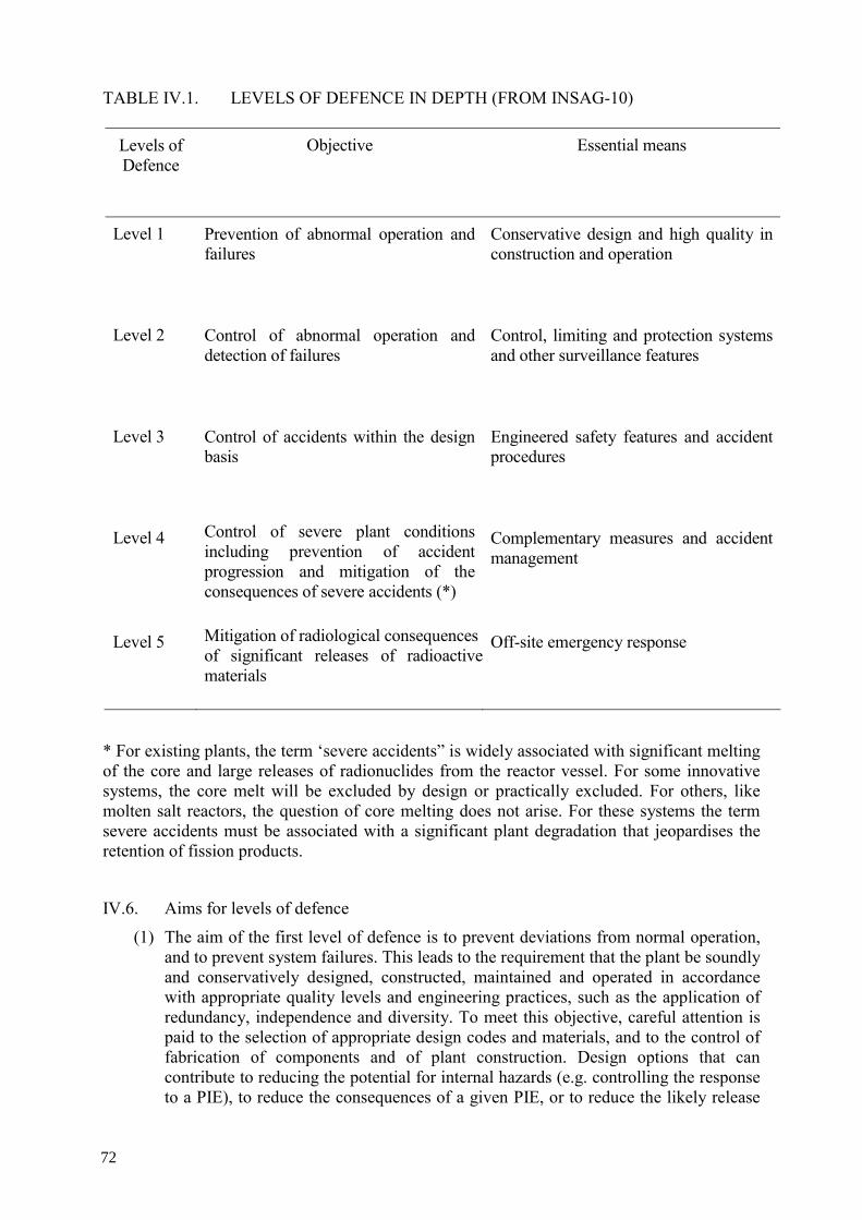
TABLE IV.1. LEVELS OF DEFENCE IN DEPTH (FROM INSAG-10)
Levels of Defence
Objective Essential means
Level 1 Prevention of abnormal operation and failures
Conservative design and high quality in construction and operation
Level 2 Control of abnormal operation and detection of failures
Control, limiting and protection systems and other surveillance features
Level 3 Control of accidents within the design basis
Engineered safety features and accident procedures
Level 4 Control of severe plant conditions including prevention of accident progression and mitigation of the consequences of severe accidents (*)
Complementary measures and accident management
Level 5 Mitigation of radiological consequences of significant releases of radioactivematerials
Off-site emergency response
* For existing plants, the term ‘severe accidents” is widely associated with significant melting of the core and large releases of radionuclides from the reactor vessel. For some innovative systems, the core melt will be excluded by design or practically excluded. For others, like molten salt reactors, the question of core melting does not arise. For these systems the term severe accidents must be associated with a significant plant degradation that jeopardises the retention of fission products.
IV.6. Aims for levels of defence
(1) The aim of the first level of defence is to prevent deviations from normal operation, and to prevent system failures. This leads to the requirement that the plant be soundly and conservatively designed, constructed, maintained and operated in accordance with appropriate quality levels and engineering practices, such as the application of redundancy, independence and diversity. To meet this objective, careful attention is paid to the selection of appropriate design codes and materials, and to the control of fabrication of components and of plant construction. Design options that can contribute to reducing the potential for internal hazards (e.g. controlling the response to a PIE), to reduce the consequences of a given PIE, or to reduce the likely release
72

source term following an accident sequence contribute at this level of defence. Attention is also paid to the procedures involved in the design, fabrication, construction and in-service plant inspection, maintenance and testing, to the ease of access for these activities, to the way the plant is operated and to how operational experience is utilized. This whole process is supported by a detailed analysis, which determines the operational, and maintenance requirements for the plant.
(2) The aim of the second level of defence is to detect and intercept deviations from normal operational states in order to prevent anticipated operational occurrences from escalating to accident conditions. This is in recognition of the fact that some PIEs are likely to occur over the service lifetime of a nuclear power plant, despite the care taken to prevent them. This level necessitates the provision of specific systems as determined in the safety analysis and the definition of operating procedures to prevent or minimize damage from such PIEs.
(3) For the third level of defence, it is assumed that, although very unlikely, the escalation of certain anticipated operational occurrences or PIEs may not be arrested by a preceding level and a more serious event may develop. These unlikely events are anticipated in the design basis for the plant, and inherent safety features, fail-safe design, additional equipment and procedures are provided to control their consequences and to achieve stable and acceptable plant states following such events. This leads to the requirement that engineered safety features be provided that are capable of leading the plant first to a controlled state, and subsequently to a safe shutdown state, and which maintain at least one barrier for the confinement of radioactive material. An increased use of inherent safety features could strengthen accident prevention in innovative nuclear installations
(4) The aim of the fourth level of defence is to address severe plant conditions in which the design basis may be exceeded and to ensure that radioactive releases are kept as low as practicable. The most important objective of this level is the protection of the confinement function. This may be achieved by complementary measures and procedures to prevent accident progression, and by mitigation of the consequences of selected severe accidents, in addition to accident management procedures. The protection provided by at least one barrier for the confinement may be demonstrated using best estimate methods.
(5) The fifth and final level of defence is aimed at mitigation of the radiological consequences of potential releases of radioactive materials that may result from accident conditions. This requires the provision of an adequately equipped emergency control centre, and plans for the on-site and off-site emergency response.
IV.7. In present practice, a relevant aspect of the implementation of defence in depth is the provision in the design of a series of physical barriers to confine the radioactive material at specified locations. The number of physical barriers that will be necessary will depend on the potential internal and external hazards, and the potential consequences of failures. The barriers may be in the form of the fuel matrix, the fuel cladding, the reactor coolant system pressure boundary and the confinement.
From an operational point of view the levels of defence in depth can be correlated to different operational limits as illustrated in Figure IV.1.
73
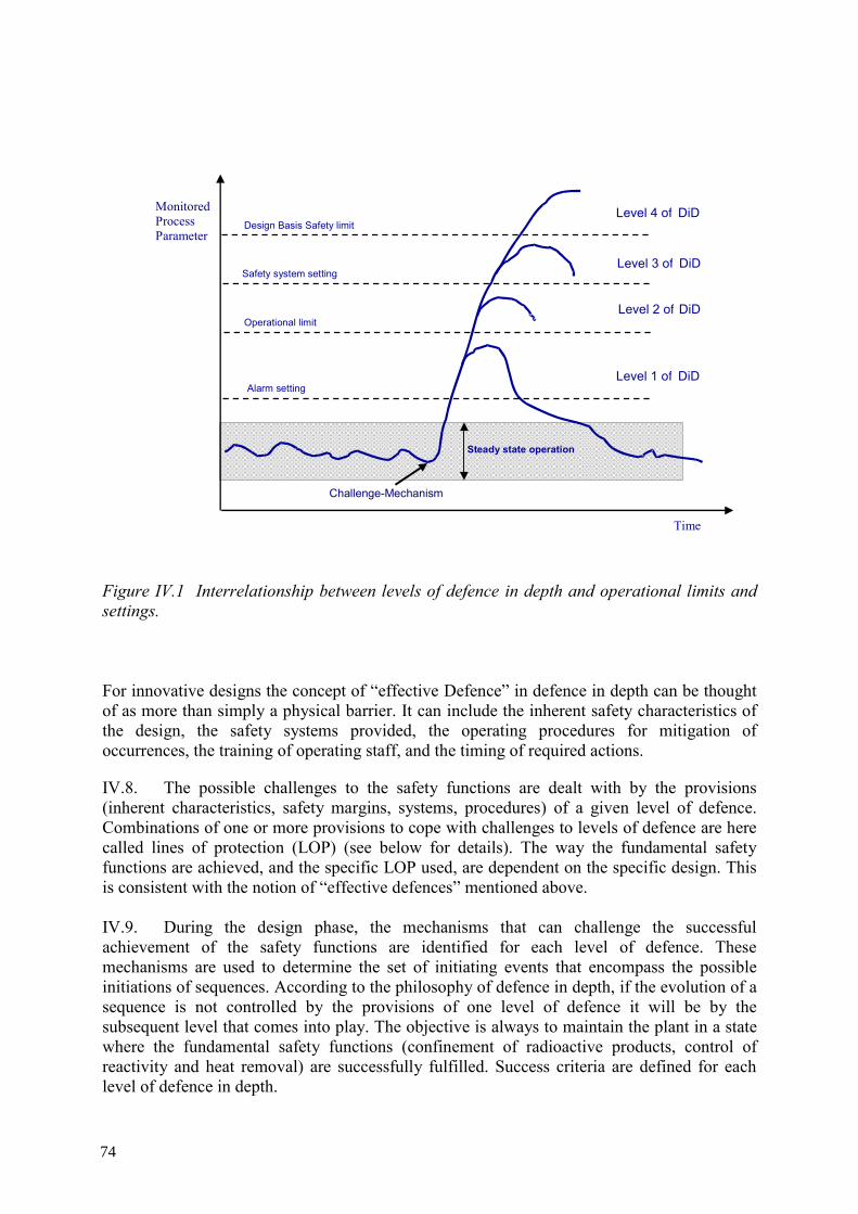
Monitored Process Parameter
Alarm setting
Steady state operation
Operational limit
Safety system setting
Design Basis Safety limit
Time
Level 4 of DiD
Level 3 of DiD
Level 2 of DiD
Level 1 of DiD
Challenge-Mechanism
Figure IV.1 Interrelationship between levels of defence in depth and operational limits and settings.
For innovative designs the concept of “effective Defence” in defence in depth can be thought of as more than simply a physical barrier. It can include the inherent safety characteristics of the design, the safety systems provided, the operating procedures for mitigation of occurrences, the training of operating staff, and the timing of required actions.
IV.8. The possible challenges to the safety functions are dealt with by the provisions (inherent characteristics, safety margins, systems, procedures) of a given level of defence. Combinations of one or more provisions to cope with challenges to levels of defence are here called lines of protection (LOP) (see below for details). The way the fundamental safety functions are achieved, and the specific LOP used, are dependent on the specific design. This is consistent with the notion of “effective defences” mentioned above. IV.9. During the design phase, the mechanisms that can challenge the successful achievement of the safety functions are identified for each level of defence. These mechanisms are used to determine the set of initiating events that encompass the possible initiations of sequences. According to the philosophy of defence in depth, if the evolution of a sequence is not controlled by the provisions of one level of defence it will be by the subsequent level that comes into play. The objective is always to maintain the plant in a state where the fundamental safety functions (confinement of radioactive products, control of reactivity and heat removal) are successfully fulfilled. Success criteria are defined for each level of defence in depth.
74

IV.10. The objective of the first level of protection is the prevention of abnormal operation and system failures. If the first level fails, an initiating event comes into play and a sequence of events is potentially initiated. Then the second level of protection will detect the failures or control the abnormal operation. Should the second level fail, the third level ensures that the safety functions are further performed by activating specific lines of protection (safety systems and other safety features). Should the third level fail, the fourth level limits accident progression through accident management, so as to prevent or mitigate severe accident conditions with external releases of radioactive materials. The last level (fifth level of protection) is the mitigation of the radiological consequences of significant external releases through the off-site emergency response. IV.11. The effectiveness of a level of defence is determined by the ability of the provisions (Lines of protection) to cope with mechanisms which challenge the performance of safety functions. The probability associated with such challenges/mechanisms, the reliability of the demanded safety provisions and the associated potential radiological consequences will define the risk for the considered accident sequence. LINES OF PROTECTION (LOP) IV.12. A line of protection (LOP) is an effective defence. This term is used to identify any group of (1) any inherent characteristic, equipment, system, etc., implemented into the safety plant architecture, (2) any procedure specified within the general plant operating procedures (e.g. human actions: preventive, protective, etc.), the objective of which is to accomplish a given safety function.
IV.13. The implemented LOPs shall fulfill the missions to prevent abnormal and accidental conditions or return the plant from the abnormal condition to a controlled safe condition and maintain it in a safe state. The LOPs are the groups of safety provisions of the design necessary to meet the established safety objectives for each level of defence in depth and for each fundamental safety function.
IV.14. The lines of protection depend on the reactor type. Their design will need to take into account simultaneously the needs for performance (to meet the safety criteria), and the safety objectives as well as the recommendations concerning, for example, reliability, redundancy, diversity, in-service inspection requirements, etc. All these are able to be quantified using probabilistic safety analyses supporting the overall design.
IV.15. As lines of protection can rely simultaneously on both active and passive systems as well as on inherent features, the safety assessment approach should consider their corresponding role to correctly take into account all the potential of the safety architecture. The LOPs can be classified into categories according to the importance to safety and their reliability. The performance of the implemented LOPs can be quantified using the probabilistic safety assessment methodology to assess the adequacy of the implementation of defence in depth. IV.16. There is no unique way to implement defence in depth (i.e., no unique technical solution to meet the safety objectives), since there are different designs, different safety requirements in different countries, different technical solutions and varying management or cultural approaches. Nevertheless, the levels of defence strategy, together with the LOP concept, provides a robust and recommended general framework to achieve safety for any type of nuclear power plants.
75

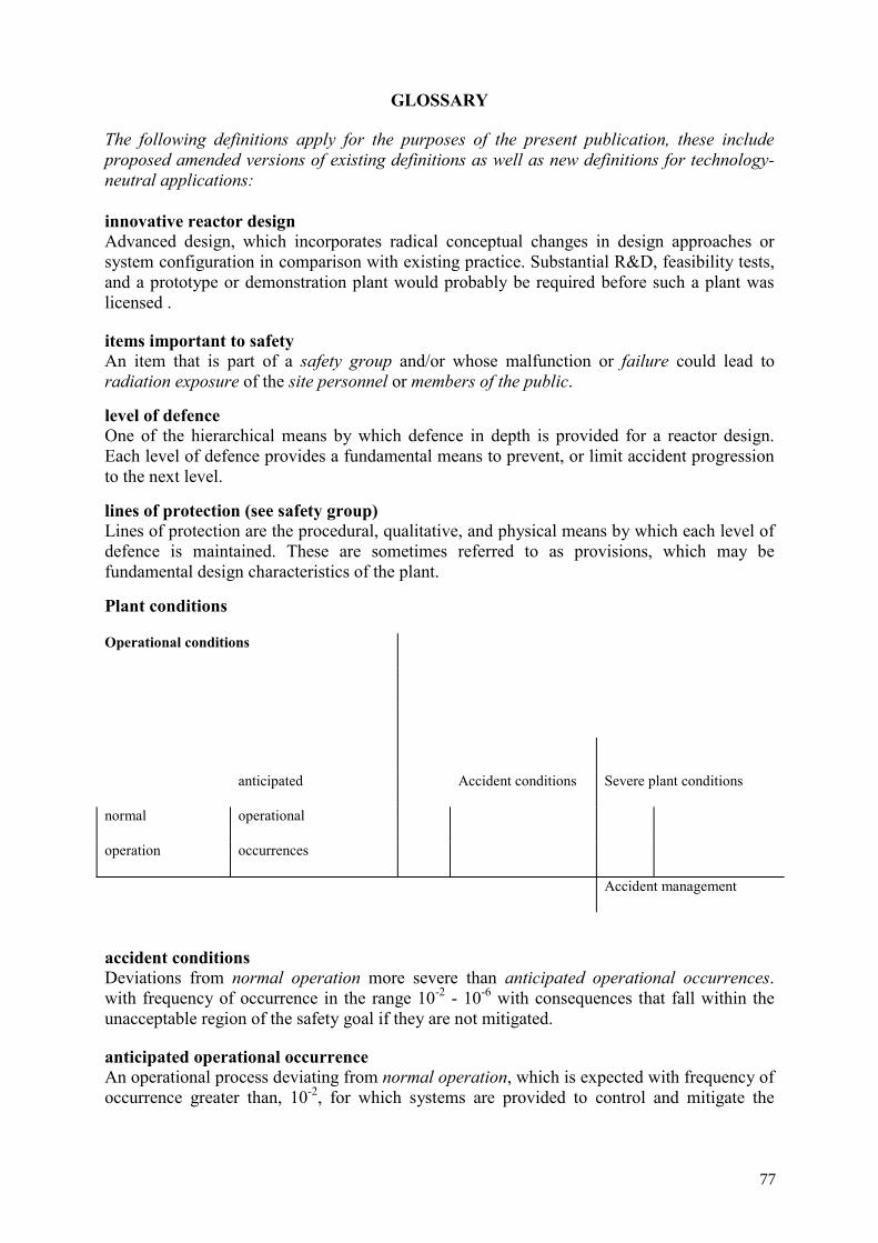
GLOSSARY
The following definitions apply for the purposes of the present publication, these include proposed amended versions of existing definitions as well as new definitions for technology-neutral applications: innovative reactor design Advanced design, which incorporates radical conceptual changes in design approaches or system configuration in comparison with existing practice. Substantial R&D, feasibility tests, and a prototype or demonstration plant would probably be required before such a plant was licensed .
items important to safety An item that is part of a safety group and/or whose malfunction or failure could lead to radiation exposure of the site personnel or members of the public. level of defence One of the hierarchical means by which defence in depth is provided for a reactor design. Each level of defence provides a fundamental means to prevent, or limit accident progression to the next level. lines of protection (see safety group) Lines of protection are the procedural, qualitative, and physical means by which each level of defence is maintained. These are sometimes referred to as provisions, which may be fundamental design characteristics of the plant. Plant conditions
accident conditions Deviations from normal operation more severe than anticipated operational occurrences. with frequency of occurrence in the range 10-2 - 10-6 with consequences that fall within the unacceptable region of the safety goal if they are not mitigated.
anticipated operational occurrence An operational process deviating from normal operation, which is expected with frequency of occurrence greater than, 10-2, for which systems are provided to control and mitigate the
Operational conditions
anticipated Accident conditions Severe plant conditions
normal operational
operation occurrences
Accident management
77

consequences of such occurrences and bring the plant back to normal conditions as soon as possible.
design basis conditions Events explicitly considered for the design. Includes normal operations, anticipated operational occurrences, accident conditions and severe plant conditions.
postulated initiating event5 An event identified as capable of leading to anticipated operational occurrences, accident conditions, or severe plant conditions, which results in the failure of the level 1 of defence in depth. probabilistic safety analysis (PSA) An integrated analysis of the plant in which plant failures are postulated using postulated initiating events with assigned frequencies for the initiating event, component failures and consequence analysis. This integrated analysis can be used to identify common mode failures and weaknesses in design to minimize the probability of the release of radioactive materials. risk dominant accident sequences Sequences identified by the PSA as being key contributors to plant risk. Based on this analysis, the design basis accidents and severe plant conditions can be established depending on the risk levels required. In addition, these risk dominant accident sequences can be used to establish the necessary safety grade and reliability requirements of key systems, structures and components. safety goal General safety target expressed by a curve (or step line) on the diagram “Frequency of Events-Consequences” which separates acceptable and non-acceptable plant conditions and provides a quantitative indicator of the overall plant safety objective. It provides the designer with a target to establish the safety architecture of the plant and to design safety systems. safety group (see also Line of protection LOP) The assembly of equipment designated to perform all actions required for a particular postulated initiating event to ensure that the limits specified in the design basis for anticipated operational occurrences and design basis accidents are not exceeded. safety system settings The levels at which protective devices are automatically actuated in the event of anticipated operational occurrences or accident conditions, to prevent safety limits being exceeded.
severe plant conditions (SPC) Event, or sequence with frequency of occurrence expected in the range 10-6 - 10-7, with consequences that fall within the unacceptable region of the safety goal if they are not mitigated. ultimate heat sink A medium to which the residual heat can always be transferred, even if all other means of removing the heat have been lost or are insufficient.
5 For further information, see Appendix I.
78

REFERENCES
[1] INTERNATIONAL ATOMIC ENERGY AGENCY, Assessment of Defence in Depth for Nuclear Power Plants, Safety Reports Series No. 46, IAEA Vienna (2005).
[2] INTERNATIONAL ATOMIC ENERGY AGENCY, Considerations in the Development of Safety Requirements for Innovative Reactors: Application to Modular High Temperature Gas Cooled Reactors, IAEA-TECDOC-1366, IAEA, Vienna (2003).
[3] INTERNATIONAL ATOMIC ENERGY AGENCY, Safety of Nuclear Power Plants: Design, IAEA Safety Standards Series No. NS-R-1, IAEA, Vienna (2000).
[4] INTERNATIONAL ATOMIC ENERGY AGENCY, IAEA Safety Standards for Protecting People and the Environment, Fundamental Safety Principles, Safety Fundamentals No. SF-1, IAEA, Vienna (2006).
[5] INTERNATIONAL NUCLEAR SAFETY ADVISORY GROUP, Defence in Depth in Nuclear Safety, INSAG-10, IAEA, Vienna (1996).
[6] INTERNATIONAL ATOMIC ENERGY AGENCY, Site Evaluation for Nuclear Installations, IAEA Safety Standards Series No. NS-R-3, IAEA, Vienna (2003).
[7] INTERNATIONAL ATOMIC ENERGY AGENCY, Guidance for the Evaluation of Innovative Nuclear Reactors and Fuel Cycles: Report of Phase 1A of the International Project on Innovative Nuclear Reactors and Fuel Cycles (INPRO), IAEA-TECDOC-1362, IAEA, Vienna (2003).
79

CONTRIBUTORS TO DRAFTING AND REVIEW
Ascroft-Hutton, W. Nuclear Installation Inspectorate, United Kingdom
Cowley, J. Consultant, United Kingdom
Fiorini, G. Commissariat à l’énergie atomique, France
Gasparini, M. International Atomic Energy Agency
Hortal, J. Consejo de Seguridad Nuclear, Spain
Kadak, A.C. Massachusetts Institute of Technology, United States of America
Lehner, J. R. Brookhaven National Laboratory, United States of America
Zemdegs, R. Atomic Energy of Canada Limited, Canada
Consultants Meetings
Vienna, Austria: 1-5 December 2003, 23–27 August 2004,
22 November–3 December 2004, 29 May–2 June 2006
Boston, Massachusetts, United States of America: 3–7 May 2004
Technical Meeting
Vienna, Austria: 1-5 December 2003
81