proposal for restoration of the salton sea · 2017-04-20 · proposal for restoration of the salton...
TRANSCRIPT
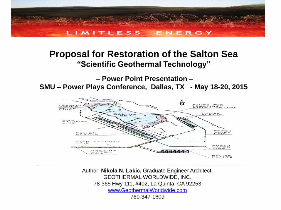
Proposal for Restoration of the Salton Sea “Scientific Geothermal Technology”
– Power Point Presentation – SMU – Power Plays Conference, Dallas, TX - May 18-20, 2015
Author: Nikola N. Lakic, Graduate Engineer Architect,
GEOTHERMAL WORLDWIDE, INC.
78-365 Hwy 111, #402, La Quinta, CA 92253
www.GeothermalWorldwide.com
760-347-1609
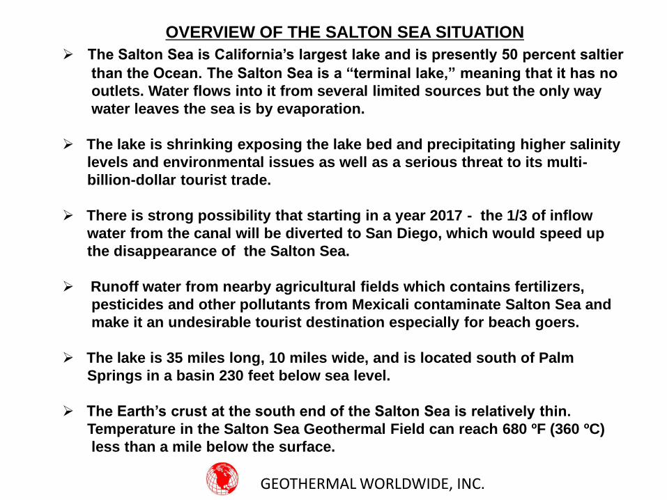
OVERVIEW OF THE SALTON SEA SITUATION
The Salton Sea is California’s largest lake and is presently 50 percent saltier
than the Ocean. The Salton Sea is a “terminal lake,” meaning that it has no
outlets. Water flows into it from several limited sources but the only way
water leaves the sea is by evaporation.
The lake is shrinking exposing the lake bed and precipitating higher salinity
levels and environmental issues as well as a serious threat to its multi-
billion-dollar tourist trade.
There is strong possibility that starting in a year 2017 - the 1/3 of inflow
water from the canal will be diverted to San Diego, which would speed up
the disappearance of the Salton Sea.
Runoff water from nearby agricultural fields which contains fertilizers,
pesticides and other pollutants from Mexicali contaminate Salton Sea and
make it an undesirable tourist destination especially for beach goers.
The lake is 35 miles long, 10 miles wide, and is located south of Palm
Springs in a basin 230 feet below sea level.
The Earth’s crust at the south end of the Salton Sea is relatively thin.
Temperature in the Salton Sea Geothermal Field can reach 680 ºF (360 ºC)
less than a mile below the surface.
GEOTHERMAL WORLDWIDE, INC.
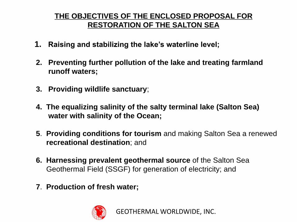
THE OBJECTIVES OF THE ENCLOSED PROPOSAL FOR
RESTORATION OF THE SALTON SEA
1. Raising and stabilizing the lake’s waterline level;
2. Preventing further pollution of the lake and treating farmland
runoff waters;
3. Providing wildlife sanctuary;
4. The equalizing salinity of the salty terminal lake (Salton Sea)
water with salinity of the Ocean;
5. Providing conditions for tourism and making Salton Sea a renewed
recreational destination; and
6. Harnessing prevalent geothermal source of the Salton Sea
Geothermal Field (SSGF) for generation of electricity; and
7. Production of fresh water;
GEOTHERMAL WORLDWIDE, INC.
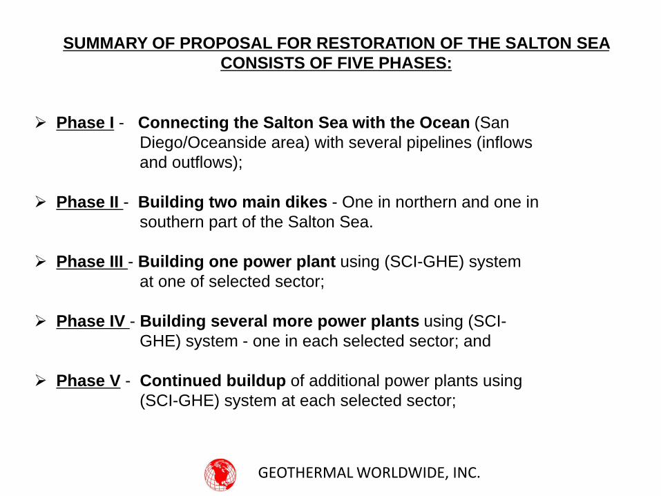
SUMMARY OF PROPOSAL FOR RESTORATION OF THE SALTON SEA
CONSISTS OF FIVE PHASES:
Phase I - Connecting the Salton Sea with the Ocean (San
Diego/Oceanside area) with several pipelines (inflows
and outflows);
Phase II - Building two main dikes - One in northern and one in
southern part of the Salton Sea.
Phase III - Building one power plant using (SCI-GHE) system
at one of selected sector;
Phase IV - Building several more power plants using (SCI-
GHE) system - one in each selected sector; and
Phase V - Continued buildup of additional power plants using
(SCI-GHE) system at each selected sector;
GEOTHERMAL WORLDWIDE, INC.
Summary of the Proposal for Restoration of the Salton Sean
GEOTHERMAL WORLDWIDE, INC.
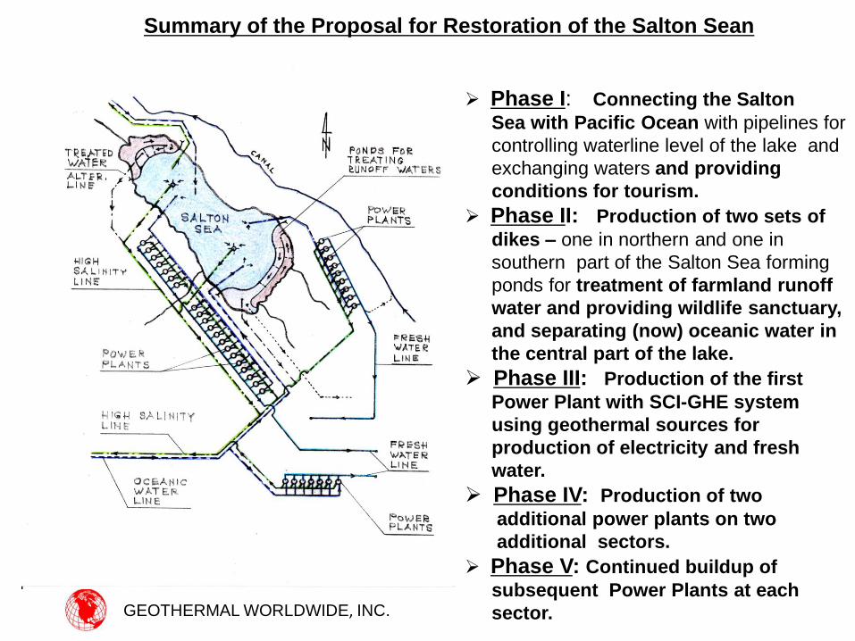
Phase I: Connecting the Salton
Sea with Pacific Ocean with pipelines for
controlling waterline level of the lake and
exchanging waters and providing
conditions for tourism.
Phase II: Production of two sets of
dikes – one in northern and one in
southern part of the Salton Sea forming
ponds for treatment of farmland runoff
water and providing wildlife sanctuary,
and separating (now) oceanic water in
the central part of the lake.
Phase III: Production of the first
Power Plant with SCI-GHE system
using geothermal sources for
production of electricity and fresh
water.
Phase IV: Production of two
additional power plants on two
additional sectors.
Phase V: Continued buildup of
subsequent Power Plants at each
sector.
ABOUT THE “SCIENTIFIC GEOTHERMAL TECHNOLOGY”
The proposal for restoration of the Salton Sea implements the Scientific Geothermal
Technology modified so to include local conditions.
The Scientific Geothermal Technology consists of:
• The Self Contained In-Ground Geothermal Generator (SCI-GGG);
• The Self Contained Heat Exchanger (SCI-GHE); and
• The IN-LINE PUMP) ;
Several designs and variations complementing each other and/or operating separately
in many different energy sector applications.
The In-Line Pump should be used for two way pipelines connecting the Salton Sea with
Pacific Ocean because this system requires the least energy for operation.
As a first option for electricity generating unit, to be implemented, for this proposal is
the (SCI-GHE) system. It has less production capacity than the (SCI-GGG) system, but is
less expensive to produce and to implement.. Later on when the (SCI-GHE) system starts
generating revenue it can be replaced with (SCI-GGG) system which at this stage requires
more investment and time for full development.
It is well known that there is an enormous source of energy under our feet whether it is
a few miles underground or on the surface in locations such as Hawaii. The question
was, until now, how to harness it expediently and efficiently?
GEOTHERMAL WORLDWIDE, INC.
ABOUT THE SCIENTIFIC GEOTHERMAL TECHNOLOGY
- SUMMARY of the “Self Contained In-Ground Heat Exchanger” (SCI-GHE) system -
The function of the “Self Contained In-Ground Heat Exchanger” (SCI-GHE)
system consists of several stages:
1. Extracting heat from prevalent geothermal sources;
2. Transferring heat up to the ground surface through completely closed
loop system (no need for geothermal fluid to be pumped to the surface
as is the case with conventional geothermal systems);
3. Using extracted heat from geothermal sources for generation of
electricity for commercial and residential use; and
4. Producing fresh water as a byproduct without spending additional
energy for its production.
5. Application for harnessing heat from Flare Stack;
6. Application for harnessing heat from established lava flow / lava tube / lava lake;
GEOTHERMAL WORLDWIDE, INC.
ENERGY OVERVIEW IN GENERAL
As population on our planet increases there is constantly
increasing demand for electricity.
Nuclear, Oil and Coal burning Power Plants with their waste
material are pollutant with serious consequences for our
environment and our existence.
Most of renewable energy technologies including solar and
wind have serious limitations such as weather conditions.
In summary – It is well known that enormous energy is
under our feet – whether it is a few miles underground or on
the surface in locations such as Hawaii, the Erta Ale volcano,
the East African Rift, etc. The question was, until now, how to
harness it expediently and efficiently?
GEOTHERMAL WORLDWIDE, INC.
Boiler
Turbine
Converter
Generator
Condenser distributor
SCI-GGG Apparatus
GEOTHERMAL WORLDWIDE, INC.
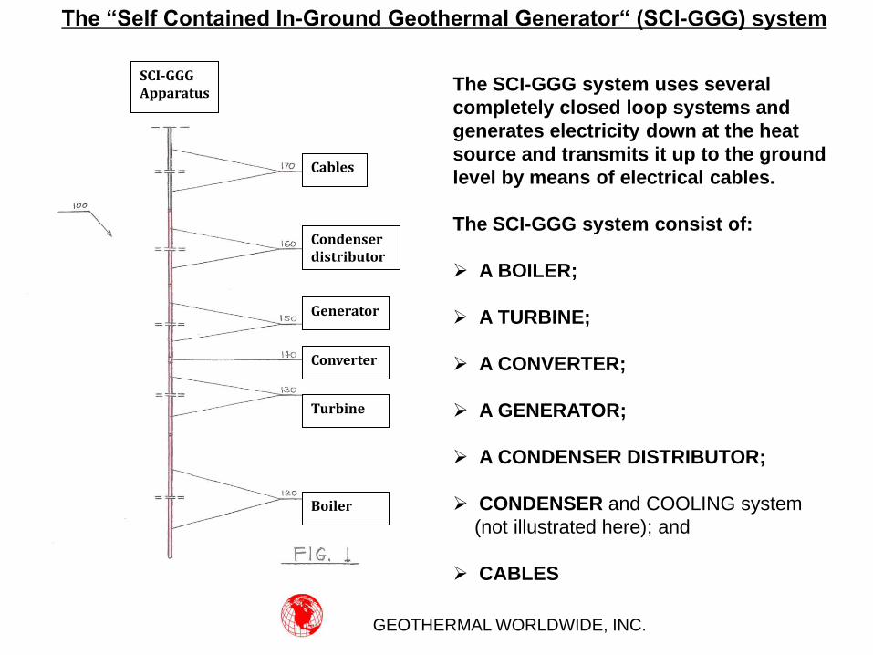
The SCI-GGG system uses several
completely closed loop systems and
generates electricity down at the heat
source and transmits it up to the ground
level by means of electrical cables.
The SCI-GGG system consist of:
A BOILER;
A TURBINE;
A CONVERTER;
A GENERATOR;
A CONDENSER DISTRIBUTOR;
CONDENSER and COOLING system
(not illustrated here); and
CABLES
Cables
The “Self Contained In-Ground Geothermal Generator“ (SCI-GGG) system
Boiler
Turbine
Converter
Generator
Condenser distributor
Cables
GEOTHERMAL WORLDWIDE, INC.
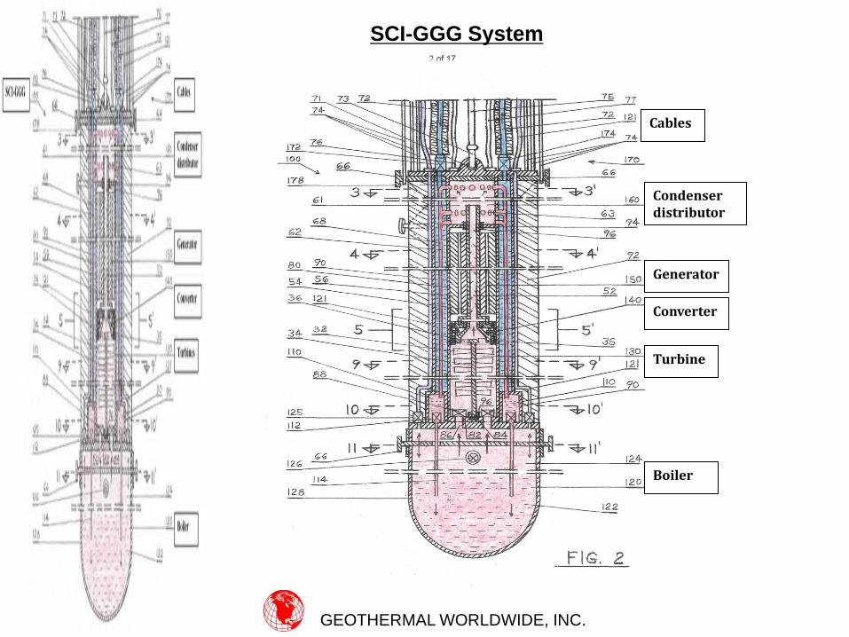
SCI-GGG System
Boiler
Turbine
Converter
Generator
Condenser distributor
Cables
GEOTHERMAL WORLDWIDE, INC.
Self Contained In-Ground Geothermal Generator (SCI-GGG)
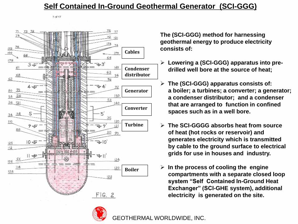
The (SCI-GGG) method for harnessing
geothermal energy to produce electricity
consists of:
Lowering a (SCI-GGG) apparatus into pre-
drilled well bore at the source of heat;
The (SCI-GGG) apparatus consists of:
a boiler; a turbines; a converter; a generator;
a condenser distributor; and a condenser
that are arranged to function in confined
spaces such as in a well bore.
The SCI-GGGG absorbs heat from source
of heat (hot rocks or reservoir) and
generates electricity which is transmitted
by cable to the ground surface to electrical
grids for use in houses and industry.
In the process of cooling the engine
compartments with a separate closed loop
system “Self Contained In-Ground Heat
Exchanger” (SCI-GHE system), additional
electricity is generated on the site.
GEOTHERMAL WORLDWIDE, INC.
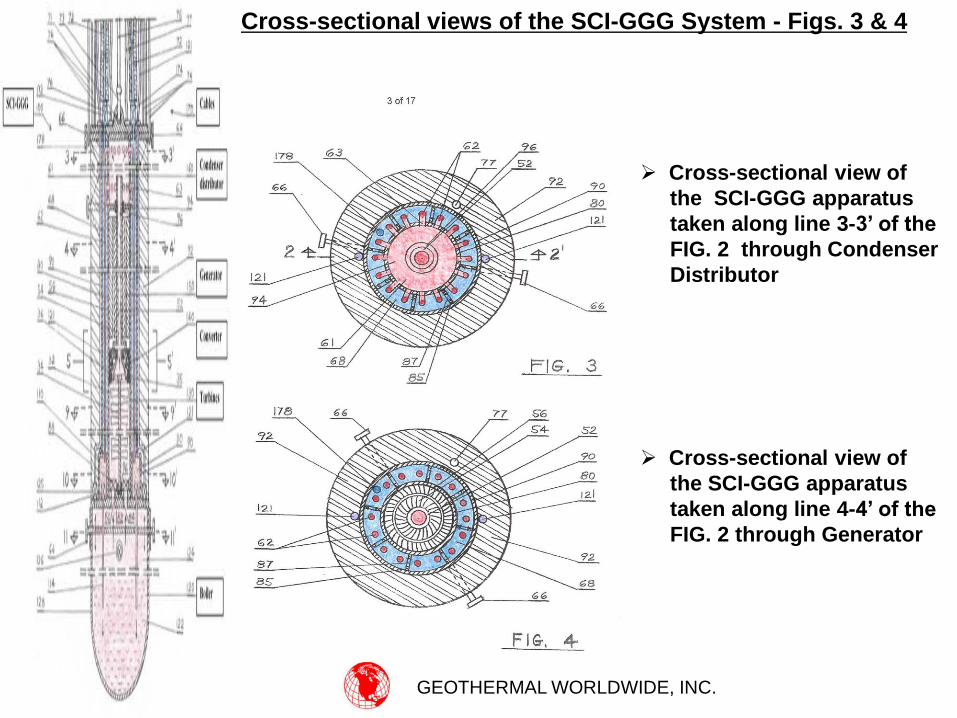
Cross-sectional view of
the SCI-GGG apparatus
taken along line 3-3’ of the
FIG. 2 through Condenser
Distributor
Cross-sectional view of
the SCI-GGG apparatus
taken along line 4-4’ of the
FIG. 2 through Generator
Cross-sectional views of the SCI-GGG System - Figs. 3 & 4
Boiler
Turbines
Converter
Generator
Condenser distributor
SCI-GGG apparatus
Heat Exchanger
GEOTHERMAL WORLDWIDE, INC.
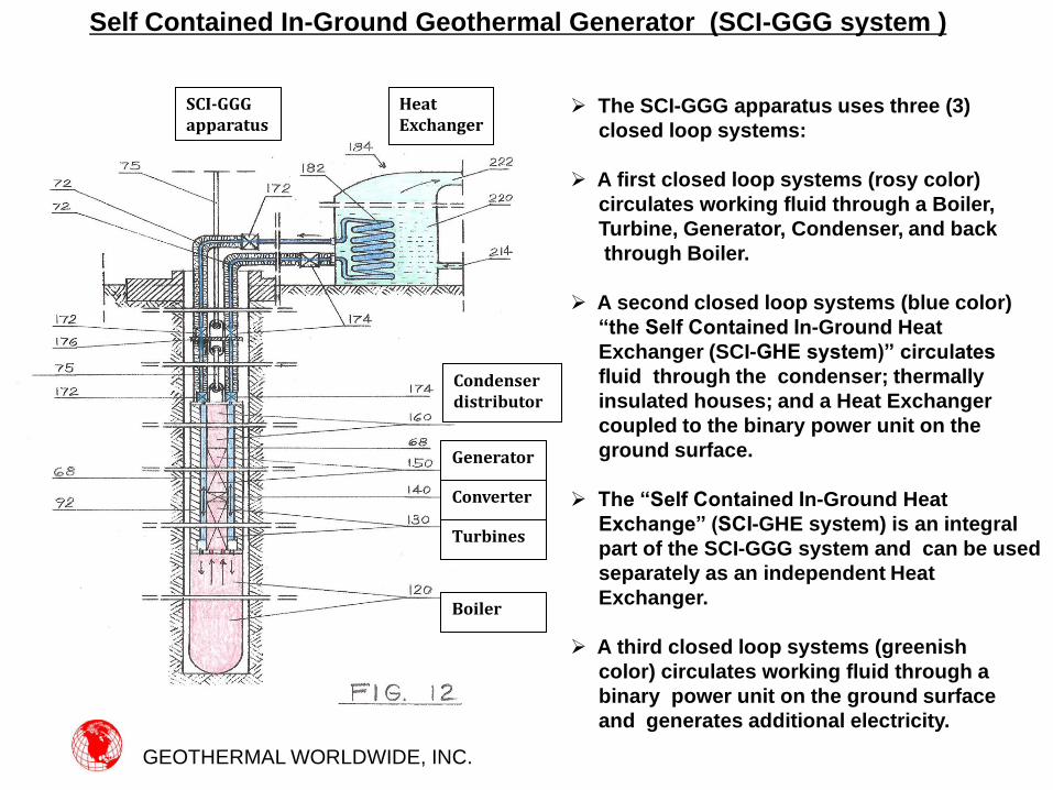
The SCI-GGG apparatus uses three (3)
closed loop systems:
A first closed loop systems (rosy color)
circulates working fluid through a Boiler,
Turbine, Generator, Condenser, and back
through Boiler.
A second closed loop systems (blue color)
“the Self Contained In-Ground Heat
Exchanger (SCI-GHE system)” circulates
fluid through the condenser; thermally
insulated houses; and a Heat Exchanger
coupled to the binary power unit on the
ground surface.
The “Self Contained In-Ground Heat
Exchange” (SCI-GHE system) is an integral
part of the SCI-GGG system and can be used
separately as an independent Heat
Exchanger.
A third closed loop systems (greenish
color) circulates working fluid through a
binary power unit on the ground surface
and generates additional electricity.
Self Contained In-Ground Geothermal Generator (SCI-GGG system )
Heat Exchanger
Heat Exchanger
GEOTHERMAL WORLDWIDE, INC.
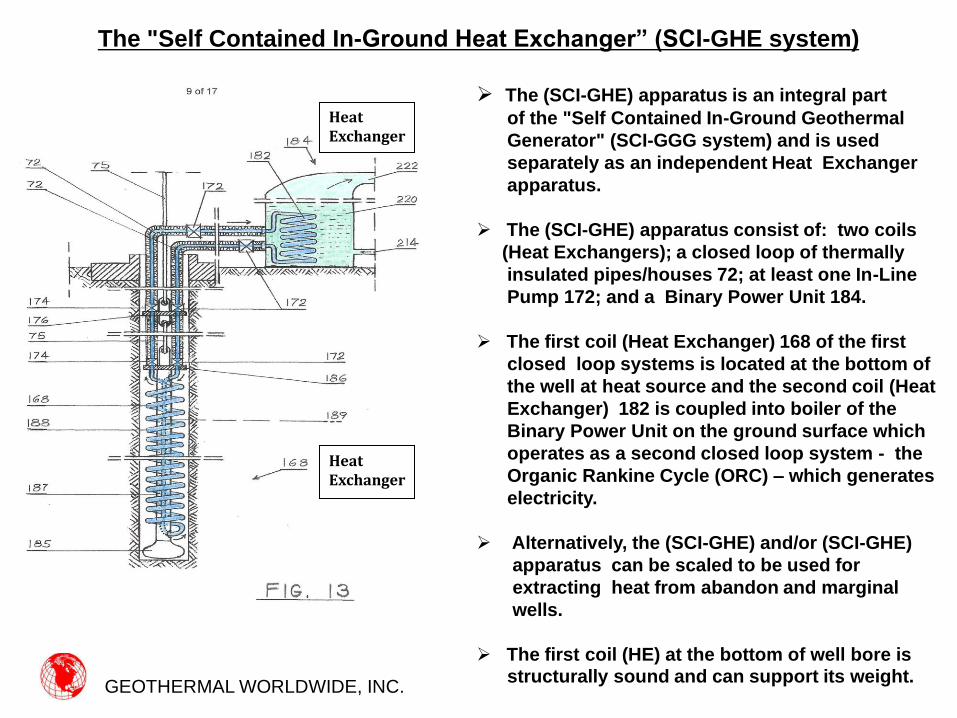
The (SCI-GHE) apparatus is an integral part
of the "Self Contained In-Ground Geothermal
Generator" (SCI-GGG system) and is used
separately as an independent Heat Exchanger
apparatus.
The (SCI-GHE) apparatus consist of: two coils
(Heat Exchangers); a closed loop of thermally
insulated pipes/houses 72; at least one In-Line
Pump 172; and a Binary Power Unit 184.
The first coil (Heat Exchanger) 168 of the first
closed loop systems is located at the bottom of
the well at heat source and the second coil (Heat
Exchanger) 182 is coupled into boiler of the
Binary Power Unit on the ground surface which
operates as a second closed loop system - the
Organic Rankine Cycle (ORC) – which generates
electricity.
Alternatively, the (SCI-GHE) and/or (SCI-GHE)
apparatus can be scaled to be used for
extracting heat from abandon and marginal
wells.
The first coil (HE) at the bottom of well bore is
structurally sound and can support its weight.
The "Self Contained In-Ground Heat Exchanger” (SCI-GHE system)
GEOTHERMAL WORLDWIDE, INC.
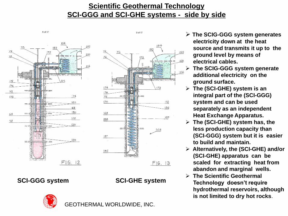
SCI-GGG system SCI-GHE system
The SCIG-GGG system generates
electricity down at the heat
source and transmits it up to the
ground level by means of
electrical cables.
The SCIG-GGG system generate
additional electricity on the
ground surface.
The (SCI-GHE) system is an
integral part of the (SCI-GGG)
system and can be used
separately as an independent
Heat Exchange Apparatus.
The (SCI-GHE) system has, the
less production capacity than
(SCI-GGG) system but it is easier
to build and maintain.
Alternatively, the (SCI-GHE) and/or
(SCI-GHE) apparatus can be
scaled for extracting heat from abandon and marginal wells. The Scientific Geothermal
Technology doesn’t require
hydrothermal reservoirs, although
is not limited to dry hot rocks.
Scientific Geothermal Technology
SCI-GGG and SCI-GHE systems - side by side
GEOTHERMAL WORLDWIDE, INC.
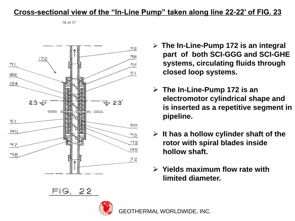
The In-Line-Pump 172 is an integral
part of both SCI-GGG and SCI-GHE
systems, circulating fluids through
closed loop systems.
The In-Line-Pump 172 is an
electromotor cylindrical shape and
is inserted as a repetitive segment in
pipeline.
It has a hollow cylinder shaft of the
rotor with spiral blades inside
hollow shaft.
Yields maximum flow rate with
limited diameter.
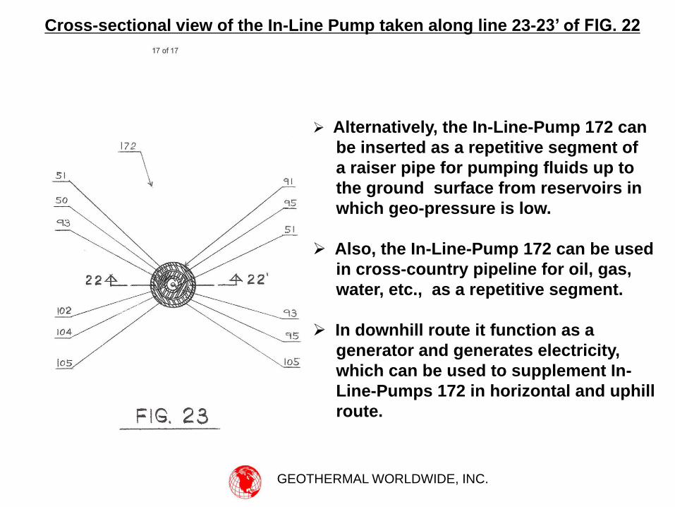
Cross-sectional view of the “In-Line Pump” taken along line 22-22’ of FIG. 23
GEOTHERMAL WORLDWIDE, INC.
Alternatively, the In-Line-Pump 172 can
be inserted as a repetitive segment of
a raiser pipe for pumping fluids up to
the ground surface from reservoirs in
which geo-pressure is low.
Also, the In-Line-Pump 172 can be used
in cross-country pipeline for oil, gas,
water, etc., as a repetitive segment.
In downhill route it function as a
generator and generates electricity,
which can be used to supplement In-
Line-Pumps 172 in horizontal and uphill
route.
Cross-sectional view of the In-Line Pump taken along line 23-23’ of FIG. 22
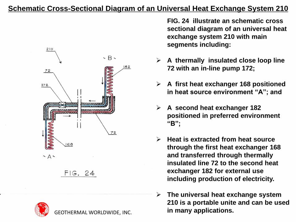
Schematic Cross-Sectional Diagram of an Universal Heat Exchange System 210
FIG. 24 illustrate an schematic cross
sectional diagram of an universal heat
exchange system 210 with main
segments including:
A thermally insulated close loop line
72 with an in-line pump 172;
A first heat exchanger 168 positioned
in heat source environment “A”; and
A second heat exchanger 182
positioned in preferred environment
“B”;
Heat is extracted from heat source
through the first heat exchanger 168
and transferred through thermally
insulated line 72 to the second heat
exchanger 182 for external use
including production of electricity.
The universal heat exchange system
210 is a portable unite and can be used
in many applications. GEOTHERMAL WORLDWIDE, INC.
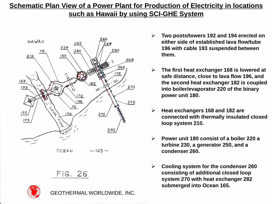
Two posts/towers 192 and 194 erected on
either side of established lava flow/tube
196 with cable 193 suspended between
them.
The first heat exchanger 168 is lowered at
safe distance, close to lava flow 196, and
the second heat exchanger 182 is coupled
into boiler/evaporator 220 of the binary
power unit 180.
Heat exchangers 168 and 182 are
connected with thermally insulated closed
loop system 210.
Power unit 180 consist of a boiler 220 a
turbine 230, a generator 250, and a
condenser 260.
Cooling system for the condenser 260
consisting of additional closed loop
system 270 with heat exchanger 282
submerged into Ocean 165.
GEOTHERMAL WORLDWIDE, INC.
Schematic Plan View of a Power Plant for Production of Electricity in locations
such as Hawaii by using SCI-GHE System
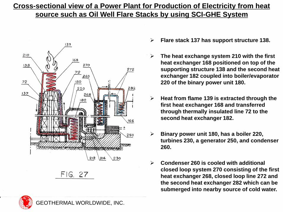
Flare stack 137 has support structure 138.
The heat exchange system 210 with the first
heat exchanger 168 positioned on top of the
supporting structure 138 and the second heat
exchanger 182 coupled into boiler/evaporator
220 of the binary power unit 180.
Heat from flame 139 is extracted through the
first heat exchanger 168 and transferred
through thermally insulated line 72 to the
second heat exchanger 182.
Binary power unit 180, has a boiler 220,
turbines 230, a generator 250, and condenser
260.
Condenser 260 is cooled with additional
closed loop system 270 consisting of the first
heat exchanger 268, closed loop line 272 and
the second heat exchanger 282 which can be
submerged into nearby source of cold water.
Cross-sectional view of a Power Plant for Production of Electricity from heat
source such as Oil Well Flare Stacks by using SCI-GHE System
GEOTHERMAL WORLDWIDE, INC.
GEOTHERMAL WORLDWIDE, INC.
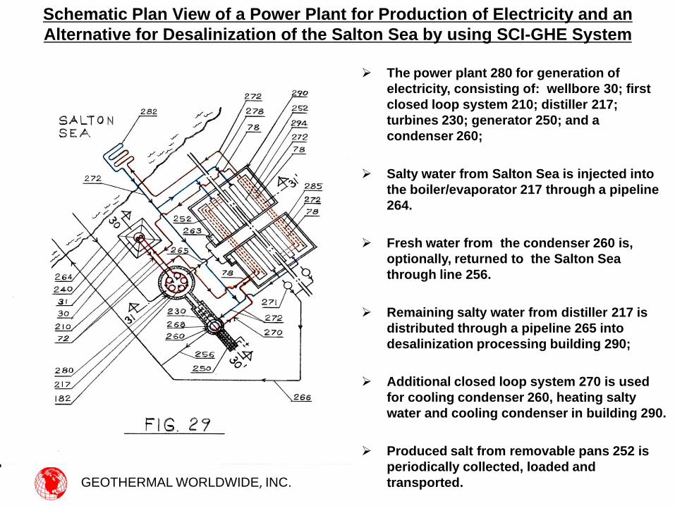
The power plant 280 for generation of
electricity, consisting of: wellbore 30; first
closed loop system 210; distiller 217;
turbines 230; generator 250; and a
condenser 260;
Salty water from Salton Sea is injected into
the boiler/evaporator 217 through a pipeline
264.
Fresh water from the condenser 260 is,
optionally, returned to the Salton Sea
through line 256.
Remaining salty water from distiller 217 is
distributed through a pipeline 265 into
desalinization processing building 290;
Additional closed loop system 270 is used
for cooling condenser 260, heating salty
water and cooling condenser in building 290.
Produced salt from removable pans 252 is
periodically collected, loaded and
transported.
Schematic Plan View of a Power Plant for Production of Electricity and an
Alternative for Desalinization of the Salton Sea by using SCI-GHE System
GEOTHERMAL WORLDWIDE, INC.
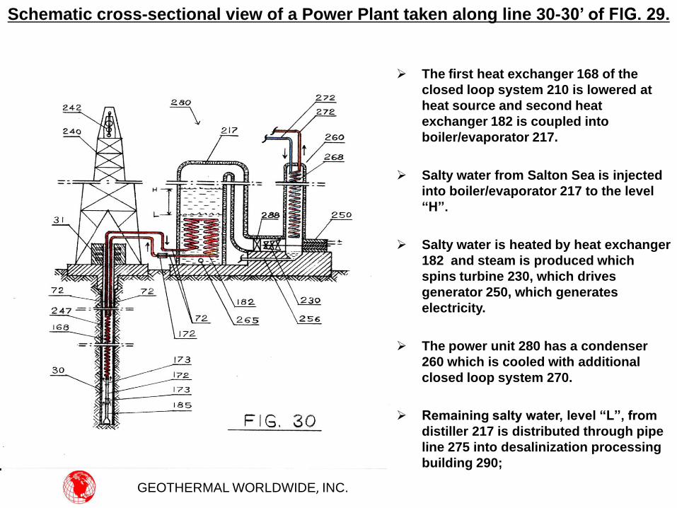
The first heat exchanger 168 of the
closed loop system 210 is lowered at
heat source and second heat
exchanger 182 is coupled into
boiler/evaporator 217.
Salty water from Salton Sea is injected
into boiler/evaporator 217 to the level
“H”.
Salty water is heated by heat exchanger
182 and steam is produced which
spins turbine 230, which drives
generator 250, which generates
electricity.
The power unit 280 has a condenser
260 which is cooled with additional
closed loop system 270.
Remaining salty water, level “L”, from
distiller 217 is distributed through pipe
line 275 into desalinization processing
building 290;
Schematic cross-sectional view of a Power Plant taken along line 30-30’ of FIG. 29.
GEOTHERMAL WORLDWIDE, INC.
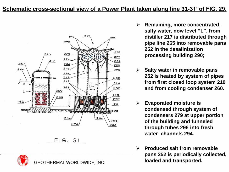
Remaining, more concentrated,
salty water, now level “L”, from
distiller 217 is distributed through
pipe line 265 into removable pans
252 in the desalinization
processing building 290;
Salty water in removable pans
252 is heated by system of pipes
from first closed loop system 210
and from cooling condenser 260.
Evaporated moisture is
condensed through system of
condensers 279 at upper portion
of the building and funneled
through tubes 296 into fresh
water channels 294.
Produced salt from removable
pans 252 is periodically collected,
loaded and transported.
Schematic cross-sectional view of a Power Plant taken along line 31-31’ of FIG. 29.
GEOTHERMAL WORLDWIDE, INC.
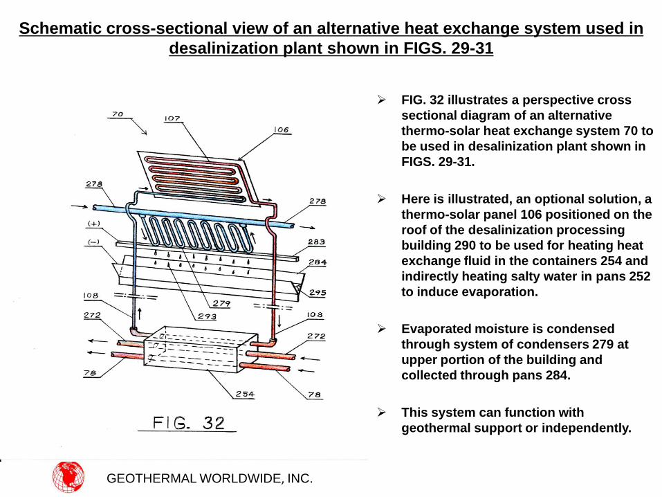
FIG. 32 illustrates a perspective cross
sectional diagram of an alternative
thermo-solar heat exchange system 70 to
be used in desalinization plant shown in
FIGS. 29-31.
Here is illustrated, an optional solution, a
thermo-solar panel 106 positioned on the
roof of the desalinization processing
building 290 to be used for heating heat
exchange fluid in the containers 254 and
indirectly heating salty water in pans 252
to induce evaporation.
Evaporated moisture is condensed
through system of condensers 279 at
upper portion of the building and
collected through pans 284.
This system can function with
geothermal support or independently.
Schematic cross-sectional view of an alternative heat exchange system used in
desalinization plant shown in FIGS. 29-31
GEOTHERMAL WORLDWIDE, INC.
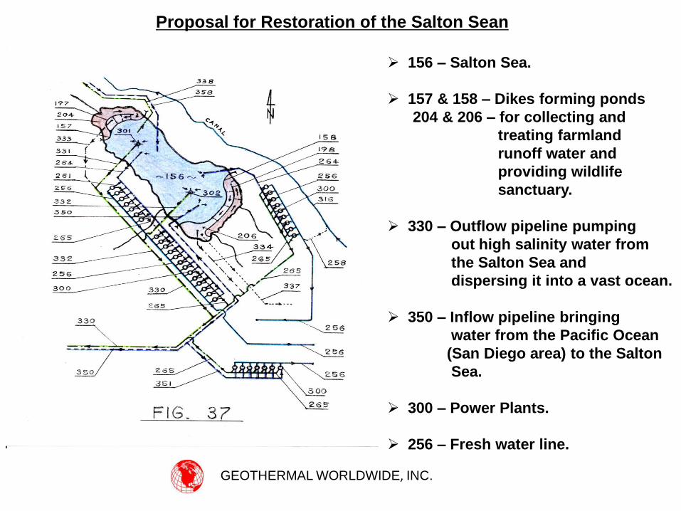
Proposal for Restoration of the Salton Sean
156 – Salton Sea.
157 & 158 – Dikes forming ponds
204 & 206 – for collecting and
treating farmland
runoff water and
providing wildlife
sanctuary.
330 – Outflow pipeline pumping
out high salinity water from
the Salton Sea and
dispersing it into a vast ocean.
350 – Inflow pipeline bringing
water from the Pacific Ocean
(San Diego area) to the Salton
Sea.
300 – Power Plants.
256 – Fresh water line.
GEOTHERMAL WORLDWIDE, INC.
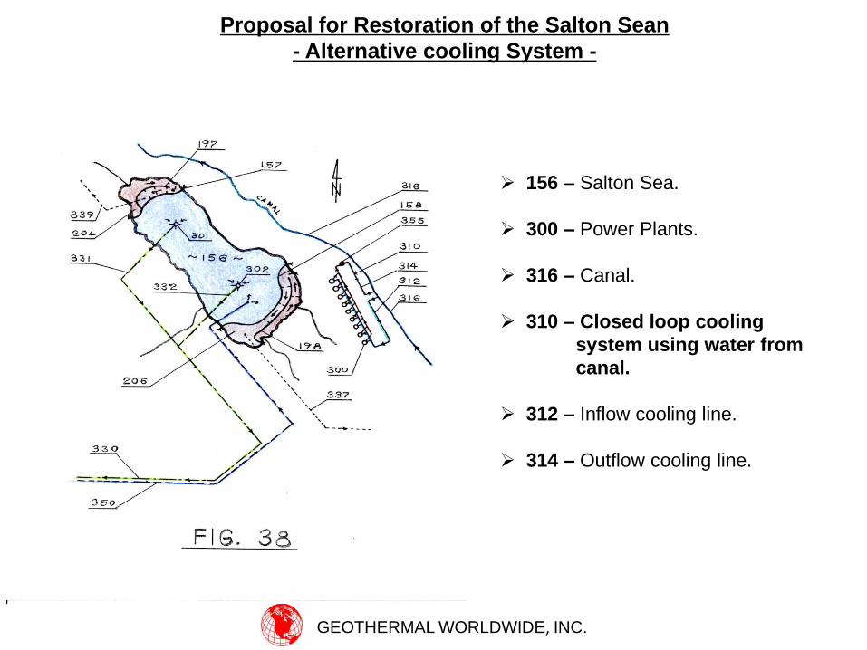
Proposal for Restoration of the Salton Sean
- Alternative cooling System -
156 – Salton Sea.
300 – Power Plants.
316 – Canal.
310 – Closed loop cooling
system using water from
canal.
312 – Inflow cooling line.
314 – Outflow cooling line.
GEOTHERMAL WORLDWIDE, INC.
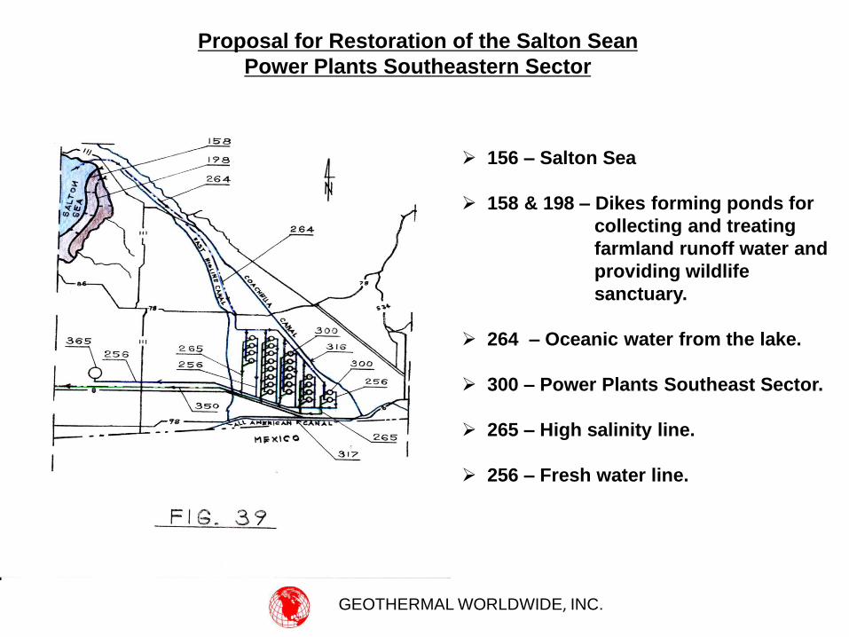
Proposal for Restoration of the Salton Sean
Power Plants Southeastern Sector
156 – Salton Sea
158 & 198 – Dikes forming ponds for
collecting and treating
farmland runoff water and
providing wildlife
sanctuary.
264 – Oceanic water from the lake.
300 – Power Plants Southeast Sector.
265 – High salinity line.
256 – Fresh water line.
GEOTHERMAL WORLDWIDE, INC.
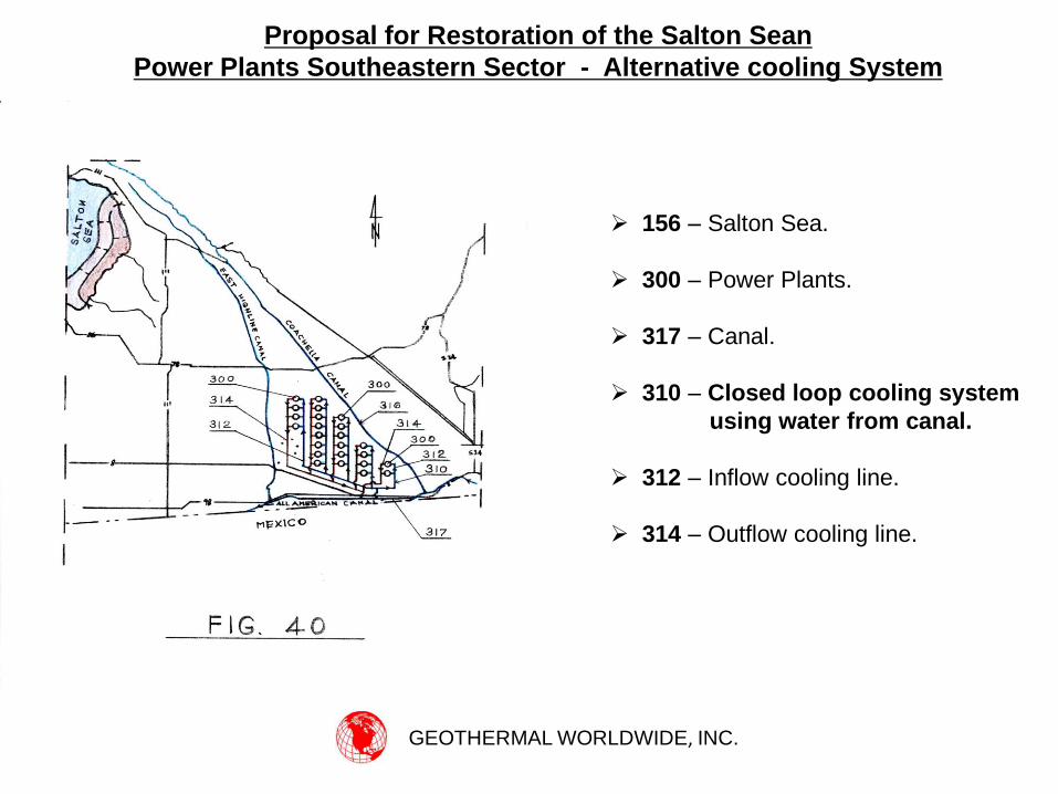
Proposal for Restoration of the Salton Sean
Power Plants Southeastern Sector - Alternative cooling System
156 – Salton Sea.
300 – Power Plants.
317 – Canal.
310 – Closed loop cooling system
using water from canal.
312 – Inflow cooling line.
314 – Outflow cooling line.
GEOTHERMAL WORLDWIDE, INC.
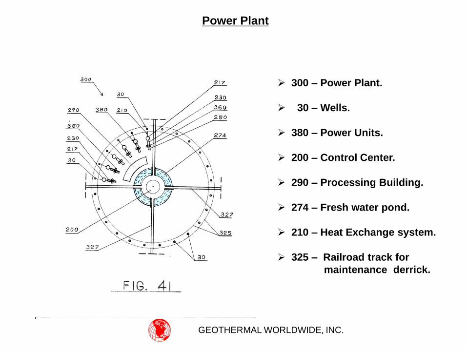
Power Plant
300 – Power Plant.
30 – Wells.
380 – Power Units.
200 – Control Center.
290 – Processing Building.
274 – Fresh water pond.
210 – Heat Exchange system.
325 – Railroad track for
maintenance derrick.
GEOTHERMAL WORLDWIDE, INC.
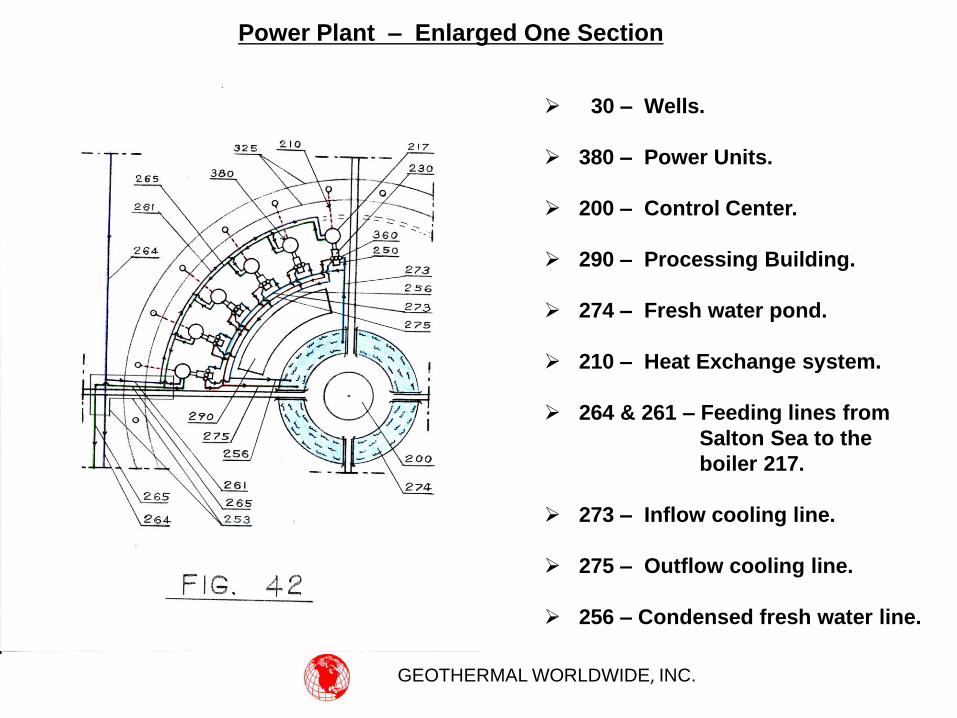
Power Plant – Enlarged One Section
30 – Wells.
380 – Power Units.
200 – Control Center.
290 – Processing Building.
274 – Fresh water pond.
210 – Heat Exchange system.
264 & 261 – Feeding lines from
Salton Sea to the
boiler 217.
273 – Inflow cooling line.
275 – Outflow cooling line.
256 – Condensed fresh water line.
GEOTHERMAL WORLDWIDE, INC.
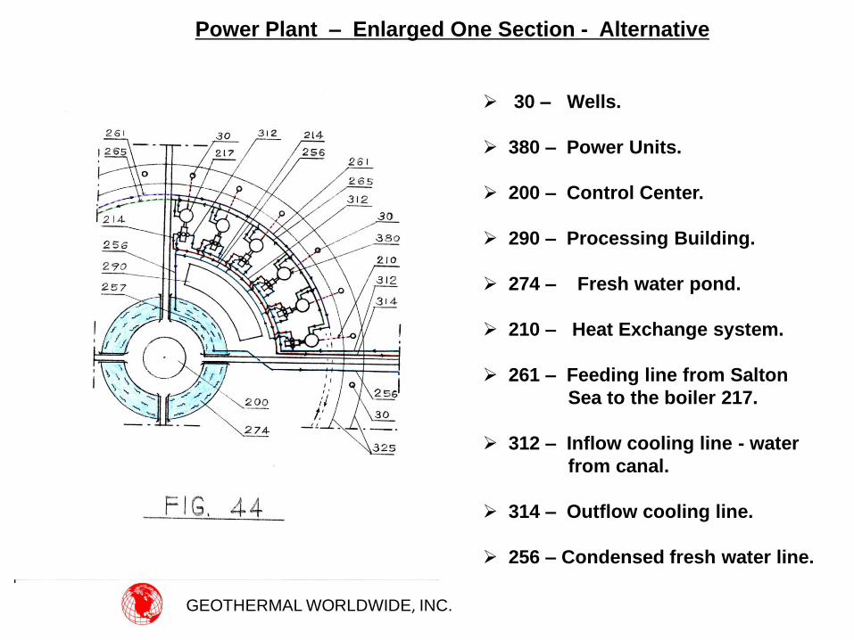
Power Plant – Enlarged One Section - Alternative
30 – Wells.
380 – Power Units.
200 – Control Center.
290 – Processing Building.
274 – Fresh water pond.
210 – Heat Exchange system.
261 – Feeding line from Salton
Sea to the boiler 217.
312 – Inflow cooling line - water
from canal.
314 – Outflow cooling line.
256 – Condensed fresh water line.
GEOTHERMAL WORLDWIDE, INC.
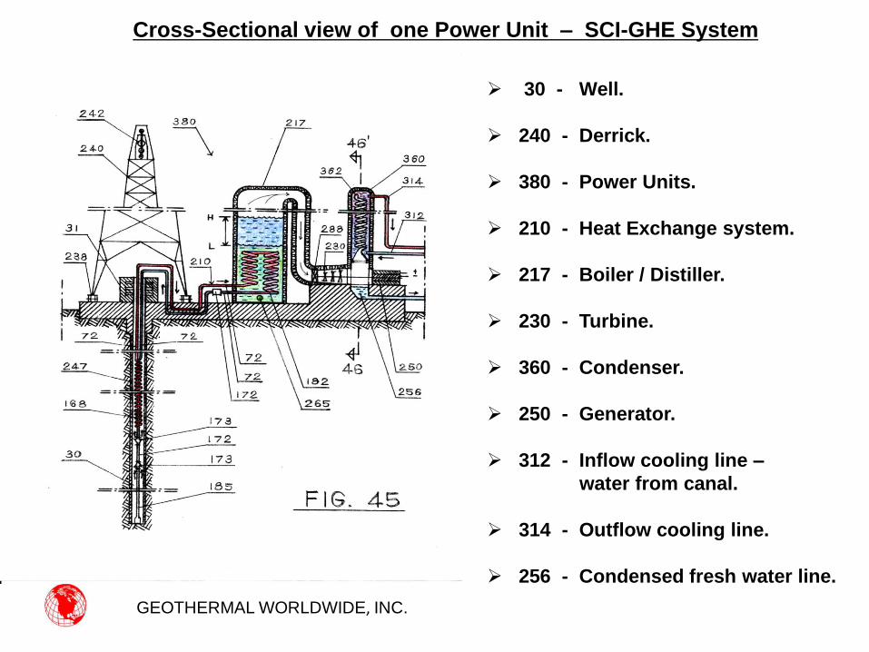
Cross-Sectional view of one Power Unit – SCI-GHE System
30 - Well.
240 - Derrick.
380 - Power Units.
210 - Heat Exchange system.
217 - Boiler / Distiller.
230 - Turbine.
360 - Condenser.
250 - Generator.
312 - Inflow cooling line –
water from canal.
314 - Outflow cooling line.
256 - Condensed fresh water line.
GEOTHERMAL WORLDWIDE, INC.
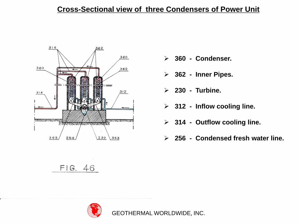
Cross-Sectional view of three Condensers of Power Unit
360 - Condenser.
362 - Inner Pipes.
230 - Turbine.
312 - Inflow cooling line.
314 - Outflow cooling line.
256 - Condensed fresh water line.
GEOTHERMAL WORLDWIDE, INC.
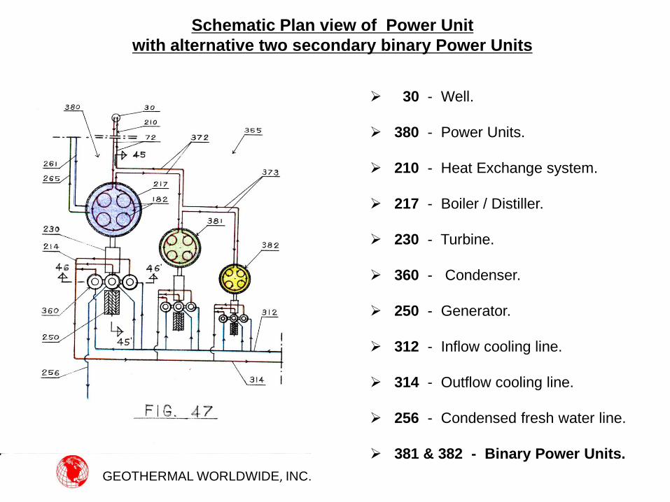
Schematic Plan view of Power Unit
with alternative two secondary binary Power Units
30 - Well.
380 - Power Units.
210 - Heat Exchange system.
217 - Boiler / Distiller.
230 - Turbine.
360 - Condenser.
250 - Generator.
312 - Inflow cooling line.
314 - Outflow cooling line.
256 - Condensed fresh water line.
381 & 382 - Binary Power Units.
GEOTHERMAL WORLDWIDE, INC.
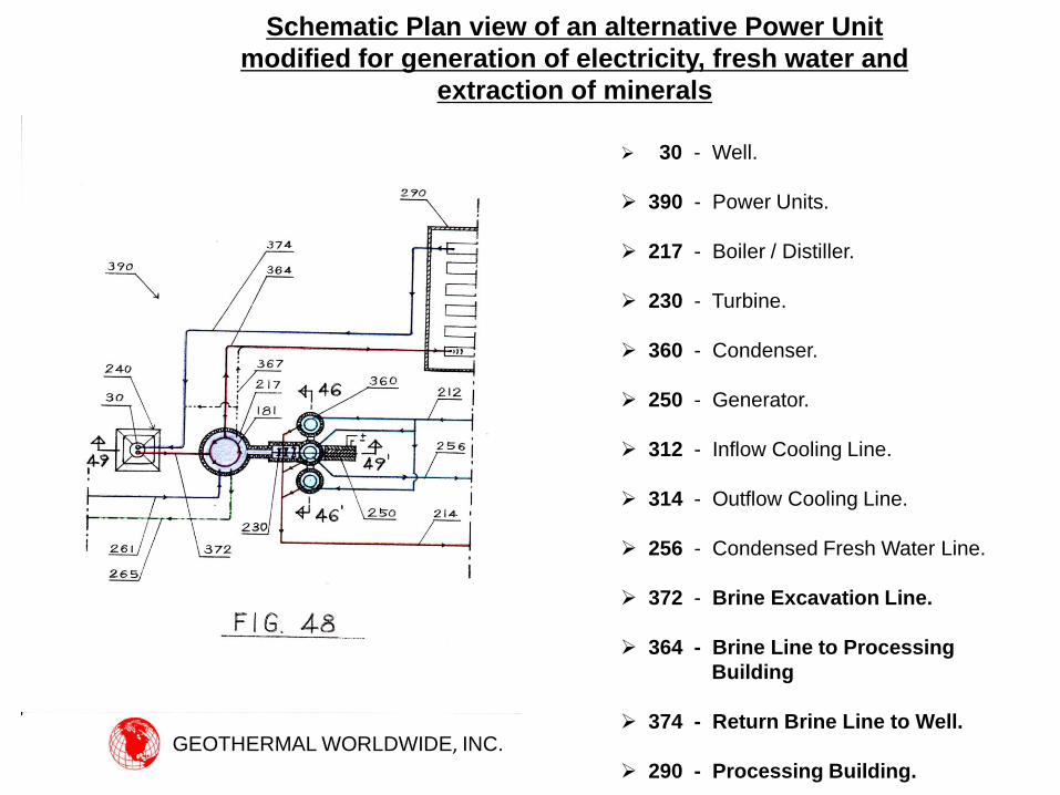
Schematic Plan view of an alternative Power Unit
modified for generation of electricity, fresh water and
extraction of minerals
30 - Well.
390 - Power Units.
217 - Boiler / Distiller.
230 - Turbine.
360 - Condenser.
250 - Generator.
312 - Inflow Cooling Line.
314 - Outflow Cooling Line.
256 - Condensed Fresh Water Line.
372 - Brine Excavation Line.
364 - Brine Line to Processing
Building
374 - Return Brine Line to Well.
290 - Processing Building.
GEOTHERMAL WORLDWIDE, INC.
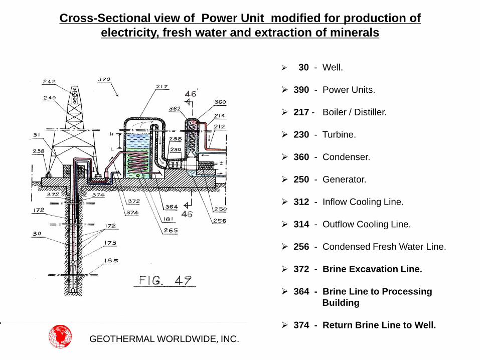
Cross-Sectional view of Power Unit modified for production of
electricity, fresh water and extraction of minerals
30 - Well.
390 - Power Units.
217 - Boiler / Distiller.
230 - Turbine.
360 - Condenser.
250 - Generator.
312 - Inflow Cooling Line.
314 - Outflow Cooling Line.
256 - Condensed Fresh Water Line.
372 - Brine Excavation Line.
364 - Brine Line to Processing
Building
374 - Return Brine Line to Well.
GEOTHERMAL WORLDWIDE, INC.
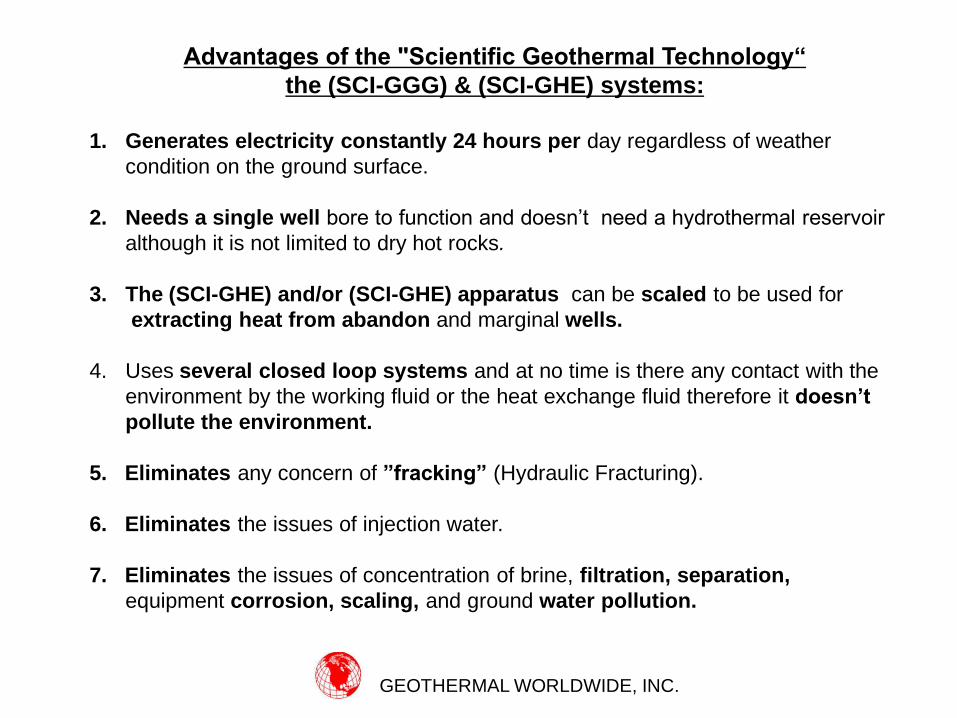
Advantages of the "Scientific Geothermal Technology“
the (SCI-GGG) & (SCI-GHE) systems:
1. Generates electricity constantly 24 hours per day regardless of weather
condition on the ground surface.
2. Needs a single well bore to function and doesn’t need a hydrothermal reservoir
although it is not limited to dry hot rocks.
3. The (SCI-GHE) and/or (SCI-GHE) apparatus can be scaled to be used for
extracting heat from abandon and marginal wells.
4. Uses several closed loop systems and at no time is there any contact with the
environment by the working fluid or the heat exchange fluid therefore it doesn’t
pollute the environment.
5. Eliminates any concern of ”fracking” (Hydraulic Fracturing).
6. Eliminates the issues of injection water.
7. Eliminates the issues of concentration of brine, filtration, separation,
equipment corrosion, scaling, and ground water pollution.
GEOTHERMAL WORLDWIDE, INC.
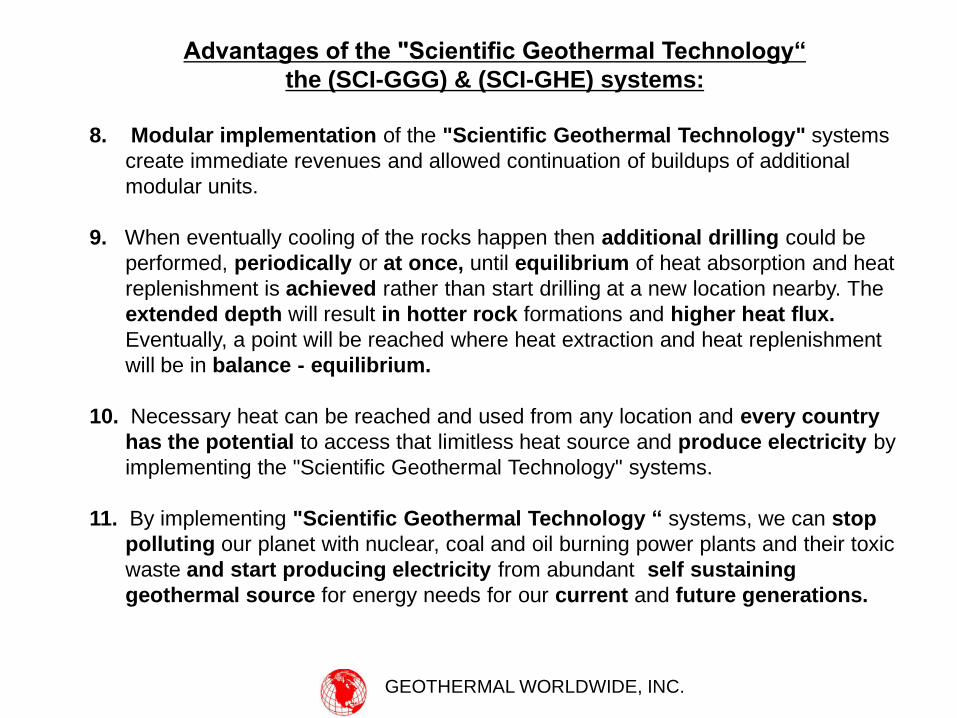
Advantages of the "Scientific Geothermal Technology“
the (SCI-GGG) & (SCI-GHE) systems:
8. Modular implementation of the "Scientific Geothermal Technology" systems
create immediate revenues and allowed continuation of buildups of additional
modular units.
9. When eventually cooling of the rocks happen then additional drilling could be
performed, periodically or at once, until equilibrium of heat absorption and heat
replenishment is achieved rather than start drilling at a new location nearby. The
extended depth will result in hotter rock formations and higher heat flux.
Eventually, a point will be reached where heat extraction and heat replenishment
will be in balance - equilibrium.
10. Necessary heat can be reached and used from any location and every country
has the potential to access that limitless heat source and produce electricity by
implementing the "Scientific Geothermal Technology" systems.
11. By implementing "Scientific Geothermal Technology “ systems, we can stop
polluting our planet with nuclear, coal and oil burning power plants and their toxic
waste and start producing electricity from abundant self sustaining
geothermal source for energy needs for our current and future generations.
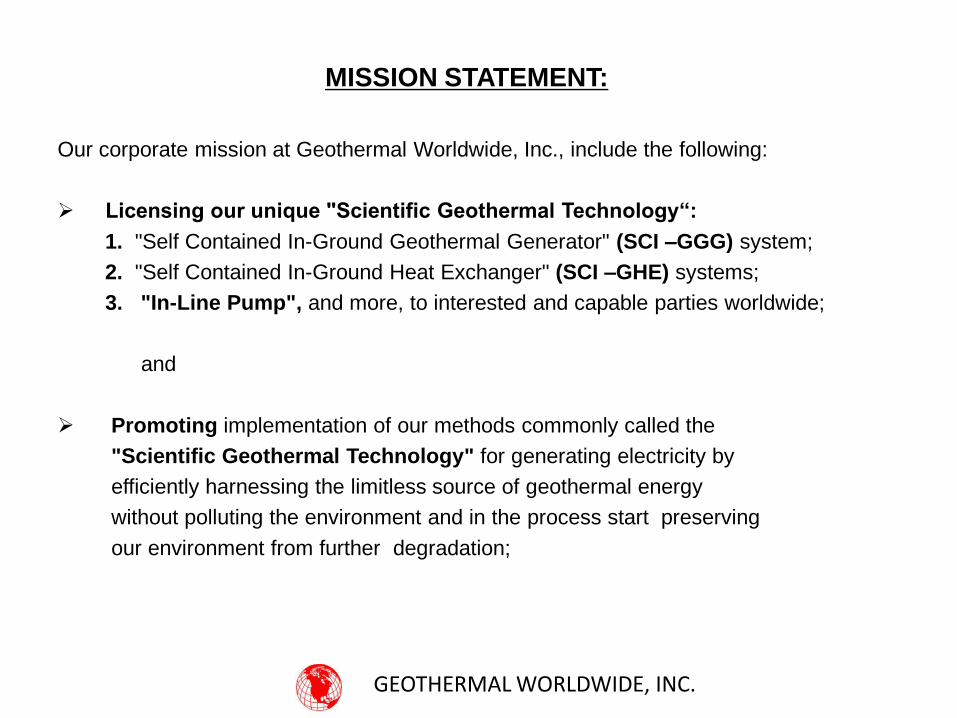
MISSION STATEMENT:
Our corporate mission at Geothermal Worldwide, Inc., include the following:
Licensing our unique "Scientific Geothermal Technology“:
1. "Self Contained In-Ground Geothermal Generator" (SCI –GGG) system;
2. "Self Contained In-Ground Heat Exchanger" (SCI –GHE) systems;
3. "In-Line Pump", and more, to interested and capable parties worldwide;
and
Promoting implementation of our methods commonly called the
"Scientific Geothermal Technology" for generating electricity by
efficiently harnessing the limitless source of geothermal energy
without polluting the environment and in the process start preserving
our environment from further degradation;
GEOTHERMAL WORLDWIDE, INC.
“We cannot solve our problems with the same thinking we
used when we created them”.
~ Albert Einstein (1879-1955) ~
**********************************
“All truth passes through three stages:
• First, it is ridiculed;
• Second, it is violently opposed; and
• Third, it is accepted as self-evident”.
• ~ Arthur Schopenhauer (1788-1860) ~
RELEVANT QUOTES
GEOTHERMAL WORLDWIDE, INC.