proposal for restoration of the salton sea “scientific geothermal...
TRANSCRIPT
PROPOSAL for RESTORATION of the SALTON SEA
“Scientific Geothermal Technology”
Proposer:
Nikola N. LAKIC, Architect,
Founder & CEO of Geothermal Worldwide, Inc.
78-365 Hwy 111, #402,
La Quinta, CA 92253,
USA
01-760-347-1609
01-760-333-3851 cell
www.GeothermalWorldwide.com

Proposal - SSA Geothermal Worldwide, Inc. (Scientific Geothermal Technology)
January 2015 Page 2 of 67
INDEX
PROPOSAL: …………………………………………………………………………..… 2-35
ABSTRACT: ……………………………………………………………………………. 2-4
APPENDIX: …………………………………………………………………………...... 33-64
BACKGROUND AND ADDITIONAL INFORMATION: …………………………….. 65-67
SUBMITTAL REQUIREMENTS
FOR SUBMITTING UNSOLICITED PROPOSALS
TO RESTORE THE SALTON SEA
PROPOSALS MUST INCLUDE THE FOLLOWING ELEMENTS:
Please provide as much detail as possible, including specifications, designs,
schematics, and/or maps.
1. Proposal Synopsis
Briefly describe your proposed technology or process and the problem(s) it solves. Provide
contact information and a brief discussion of your firm’s qualifications (detailed
qualification information is unnecessary, but can be included in an appendix).
Keyword List: Desalinization, Tourism, Fresh Water, Geothermal Energy, Electricity
Production, Geothermal, Energy, Electricity Generation, Renewable Energy, Environment,
Generator, Heat Exchanger, Waste Heat, Oil and Gas Recovery, Condenser, Self Contained In-
Ground Geothermal Generator, Self Contained In-Ground Heat Exchanger, Cross Country
Pipeline, In-Line Pump.
References: U.S. Patent No. 7,849,690; entitled: “Self Contained In-Ground Geothermal
Generators” (SCI-GGG); Issued on: Dec.14, 2010; U.S. Patent No. 8,281,591; entitled: “Self
Contained In-Ground Geothermal Generators” (SCI-GGG); Issued on: October 9, 2012; U.S.
Patent No. 8,713,940; entitled: “Self Contained In-Ground Geothermal Generators” (SCI-GGG);
Issued on: May 6, 2014; and several patent pending applications. Geothermal Resource Council
(GRC) - Transactions 2012, Volume 36 - Poster Presentation. Southern Methodist University
(SMU), Geothermal Conference, Dallas, Texas on May 20, 2015, - Power Point Presentation -
Title: “Harnessing Energy and Water in the Salton Sea”.
ABSTRACT:
Included is an exemplary method for restoration of the Salton Sea, which implements the
“Scientific Geothermal Technology” for exchanging water from a salty terminal lake with
oceanic water and treating current inflow and farmland runoff waters and reusing it which
otherwise would be lost in salty water of the lake. The “Self Contained In-Ground Heat
Exchanger” (SCI-GHE) system uses heat from the Salton Sea Geothermal Field (SSGF) for
Proposal - SSA Geothermal Worldwide, Inc. (Scientific Geothermal Technology)
January 2015 Page 3 of 67
generation of electricity and production of potable water. This method is self-sustained,
environmentally friendly and has great commercial potential.
The objectives of the enclosed proposal for restoration of the Salton Sea are:
1. Raising and stabilizing the lake’s waterline level;
2. Preventing further pollution of the lake and treating current inflows and farmland
runoff waters to be reused for farmland and/or refilling depleted aquifer and providing wildlife
sanctuary;
3. The equalizing salinity of the salty terminal lake (Salton Sea) water with salinity of the
Oceanic water and subsequently providing conditions for tourism; and making Salton Sea a
renewed recreational destination; and
4. Harnessing prevalent geothermal source of the Salton Sea Geothermal Field (SSGF)
for generation of electricity and production of fresh water - both having commercial value.
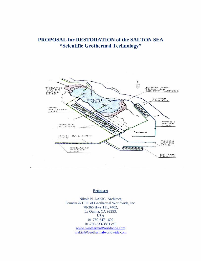
The proposal for restoration of the Salton Sea consists of five Phases:
Phase I - Connecting the Salton Sea with the Ocean (San Diego, Oceanside area) with
several pipelines (inflows and outflows);
Phase II - Building two main dikes - One in northern and one in southern part of the
Salton Sea.
Phase III - Building one power plant using (SCI-GHE) system at one of selected sector;
Phase IV - Building several more power plants using (SCI-GHE) system - one in each
selected sector; and
Phase V - Continued buildup of additional power plants using (SCI-GHE) system at each
selected sector;
About Technology:
The proposal for restoration of the Salton Sea implements the Scientific Geothermal
Technology modified so to include local conditions. The Scientific Geothermal Technology (The
Self Contained In-Ground Geothermal Generator; The Self Contained Heat Exchanger; and The
IN-LINE PUMP) consist of several designs and variations complementing each other and/or
operating separately in many different energy sector applications. The In-Line Pump should be
used for two way pipelines connecting the Salton Sea with Pacific coast because this system
requires the least energy for operation.
As a first option for electricity generating unit, to be implemented, for this proposal is the “Self
Contained In-Ground Heat Exchanger” (SCI-GHE) system. It has less production capacity than
the Self Contained In-Ground Geothermal Generator (SCI-GGG) system, but is less expensive to
produce and to implement. Later on when the (SCI-GHE) system starts generating revenue it can
be replaced with (SCI-GGG) system which at this stage requires more investment and time for
full development.
Proposal - SSA Geothermal Worldwide, Inc. (Scientific Geothermal Technology)
January 2015 Page 4 of 67
In summary: The function of the “Self Contained In-Ground Heat Exchanger” (SCI-GHE) system
consists of several stages:
1. Extracting heat from prevalent geothermal sources;
2. Transferring heat up to the ground surface through completely closed loop system (no
need for geothermal fluid to be pumped to the surface as is the case with conventional geothermal
systems);
3. Using extracted heat from geothermal sources for generation of electricity for
commercial and residential use; and
4. Producing potable water as a byproduct without spending additional energy for its
production.
It is well known that there is an enormous source of energy under our feet whether it is a few
miles underground or on the surface in locations such as Hawaii. The question was, until now,
how to harness it expediently and efficiently?
2. Problem Definition
Many proposals that we receive suggest that a particular technology or process will “fix”
the Sea. Oftentimes the same proposals do not define what problem or issue is being fixed.
The guidelines referenced reports describe various physical qualities of the Sea and we
suggest referring to these reports in your problem definition.
The Salton Sea is California’s largest lake and is presently about 50 percent saltier than the
ocean. The Salton Sea is a “terminal lake,” meaning that it has no outlets. Water flows into it
from several limited sources, but the only way water leaves the sea is by evaporation. The lake is
currently 35 miles long, 10 miles wide, and is located south of Palm Springs in a basin 230 feet
below sea level. The Salton Sea Geothermal Field (SSGF) has a high salinity and the core
temperature is high. The earth’s crust at the south end of the Salton Sea is relatively thin.
Temperatures in the Salton Sea Geothermal Field can reach 680 ⁰F less than a mile below the
surface. There are already several conventional geothermal power plants in the area.
Runoff water from nearby farmland which contains fertilizers, pesticides and other pollutants
from Mexicali, Mexico, contaminate Salton Sea and make it an undesirable tourist destination
especially for beach goers.
The runoff water has been decreasing and is set to decline dramatically after 2017, when more
water will be transferred from the canal (Colorado River) to San Diego County and the Coachella
Valley under a water transfer deal known as Quantification Settlement Agreement, or QSA,
which would speed up the disappearance of the Salton Sea.
As the lake level drops, exposing the lake bed and precipitating higher salinity levels, increasing
amounts of dust will blow from exposed shorelines. That dust could pose serious health threats in
an area with high rates of asthma and other respiratory illnesses as well as a serious threat to its
multi-billion-dollar tourist trade.
In a recent report, the Oakland-based Pacific Institute projected that without action to address the
Proposal - SSA Geothermal Worldwide, Inc. (Scientific Geothermal Technology)
January 2015 Page 5 of 67
Salton Sea’s deterioration, the long-term social and economic costs — in higher health care costs
and lower property values, among other costs — could range between $29 billion and $70 billion
over the next 30 years.
3. Design
Please address the following questions:
How would the technology/process be applied at the Salton Sea?
The objectives of the enclosed concept for restoration of the Salton Sea are:
1. Raising and stabilizing the lake’s waterline level by connecting the Salton Sea with
Pacific coast (Phase I);
2. Preventing further pollution of the lake by building two main dikes forming a central
mass of water and two peripheral reservoirs for containing and treating current inflow and
farmland runoff waters and reusing it, and providing wildlife sanctuary (Phase II);
3. The equalizing salinity of the salty terminal lake (Salton Sea) water with salinity of
the Oceanic water and subsequently providing conditions for tourism and making Salton Sea a
renewed recreational destination (Phase I & II); and
4. Harnessing prevalent geothermal source of the Salton Sea Geothermal Field
(SSGF) for generation of electricity and production of potable water – both having
commercial value (Phase III, IV & V).
Phase I:
Phase I consists of building an ocean pipeline system connecting the Salton Sea with
Pacific coast - San Diego or Oceanside area. The pipeline may have preferably 10 pipelines (8
inflow and 2 outflow) following FWY 8 or FWY 10 to Beaumont, then 79, Temecula, etc. or
around the mountains through Riverside or any other preferred corridor. Having Phase I finished
we would be able to pump out high salinity water from the bottom of the Salton Sea, where high
salinity water because of higher density is accumulated, and inject it into the Pacific Ocean and
bring ocean water into the Salton Sea. By connecting the Salton Sea with the Ocean we would be
able to control the level of the Salton Sea and equalize (reduce) salinity of the Salton Sea with the
salinity of the Ocean. Why San Diego area and not the Sea of Cortez?
The Sea of Cortez has in general stationary water and we may end up exchanging the same fluid.
Pacific coast has strong current and high salinity water from the Salton Sea will disperse into the
vast Ocean without negative effect on marine life. Also, this way we will eliminate “other country
issue”. Alternatively, the ocean pipeline system may comprise at least three ocean pipelines
fluidly connecting an ocean with a central mass of water in a salty terminal lake, such as the
Salton Sea. Two of the at least three ocean pipelines may provide inflow into the salty terminal
lake and one pipeline may provides outflow from the salty terminal lake for controlling the lake
water level.
Phase II:
Phase II prevents further pollution of the Salton Sea and providing sanctuary for wildlife.
Phase II consists of building two main dikes forming a central mass of water and two peripheral
Proposal - SSA Geothermal Worldwide, Inc. (Scientific Geothermal Technology)
January 2015 Page 6 of 67
reservoirs - one in northern and one in southern part of the Salton Sea – for containing and
treating current inflow and runoff water from nearby farmland before pumping it back and
reusing it for farmland. An example for the treatment of wastewater can be the Arcata
Wastewater Treatment Plant and Wildlife Sanctuary. It is an innovative sewer management
system employed by the city of Arcata, California. A series of oxidation ponds, treatment
wetlands and enhancement marshes are used to filter sewage waste. By separating the lake in
three sections, all current inflow water will be available for farmland and/or refilling depleted
aquifer which otherwise would be lost. Alternatively, water from reservoirs, at least earlier salty
fills, can be pumped into “outflow” pipeline(s) for dispersing it into vast Pacific Ocean or can be
injected into wells for forming or maintaining geothermal reservoirs for better heat transfer to the
heat exchange system.
Benefits of Phase I & II:
1. By separating the lake in three sections, all current inflow water will be available for
farmland and/or refilling depleted aquifer which otherwise would be lost. By saving and
restoring the Salton Sea, we will continue having a substantial water surface of now oceanic
water in our proximity which has a positive effect on our local climate, tourism and economy.
2. After several years, the central section of the Salton Sea will contain mostly oceanic
water. By controlling inflow and outflow at the Salton Sea, we can produce a surplus of (now)
oceanic water to be used for feeding geothermal power plants for generation of electricity and
production of potable water.
3. As a renewed recreational destination the Salton Sea area will flourish with tourism.
Beaches can operate all year around. It would provide a base for building memorable restaurants,
resorts and waterfront communities.
4. The wildlife sanctuary will thrive and ecosystem will benefit.
Consequences if we don’t restore the Salton Sea:
1. If we do not restore and save the Salton Sea it will dry out with the exception of one or
two relatively small ponds which will have extremely high salt concentration and will be toxic. A
huge lake bed will be exposed and we would encounter negative effects such as dust storms and
health issues associated with it such as asthma and other respiratory diseases;
2. Already established wildlife will gradually disappear;
3. Real estate value depreciation in nearby areas and subsequently reduction in businesses
and population will occur. In a recent report, the Oakland-based Pacific Institute projected that
without action to address the Salton Sea’s deterioration, the long-term social and economic costs
— in higher health care costs and lower property values, among other costs — could range
between $29 billion and $70 billion over the next 30 years.
Cost estimate for Phase I & II
This proposal is a preliminary design explaining the feasibility of the concept. The
second stage would require collaboration with potential contractors and would contain more
details, including more detailed cost estimate, which would follow with the final production
Proposal - SSA Geothermal Worldwide, Inc. (Scientific Geothermal Technology)
January 2015 Page 7 of 67
design. After consulting with engineers in the pipeline business, I have been informed that range
of cost today of installed pressure pipe of 48-inch diameter in various terrains would be $600 -
$1,000 per linear foot. I used most conservative option $1,000 per linear foot. This is still a rough
cost estimate, a few adjustments still can be made, but at least we have a bulk cost estimate for
evaluating the proposal.
It means that connecting the Salton Sea with Pacific Ocean (San Diego area) distance
about 80 miles (about 20 miles mountain terrain and about 60 miles relatively flat terrain ) comes
to: 80 miles x 10 pipelines = 800 miles of pipelines could cost about $4.3 billion. To add several
pump stations, several freeway underpasses, and permits - it still might be under $5 billion. I
believe that two main dikes (about 15 miles), separating the Salton Sea and several secondary
dikes (another 15 miles), including treatment plants, could cost another billion or two which
would end up to about $7 billion.
To start several power plants on several sectors around the Salton Sea could take another
billion or two. Proposed power plants consist of 24 well-bores and with many projected power
plants we need to implement a new system for drilling faster, deeper and wider wellbores.
The new drilling system is more expensive at this earlier stage because of development cost, but
in the long term it is better and less expensive solution.
It means that we can restore the Salton Sea with less than 10 billion. A portion of the
revenue from those several power plants in several sectors around the Salton Sea can be used for
financing subsequent power plants. This will provide conditions for the private sector to get
involved with more confidence. This process will continue to grow and the future generations
will continue building on it.
In the meantime, by filling central part of the Salton Sea with oceanic water, the private
sector could start developing resorts, beaches, hotels, motels, etc., and start generating revenue
from tourism.
It is important to understand the importance of implementation of this proposal,
especially Phases I & II, for the restoration of the Salton Sea and the ratio of its cost and benefits.
Whatever initial cost to build the Phase I & II is going to be - $4 billion, $5 billion or even $6
billion - it is imperative that we do it because it is the foundation for subsequent phases which
have great potential for generating revenue in hundreds billion of dollars, economic development
and clean environment. The In-Line Pump (illustrated in FIGS. 22 & 23) should be used for two
way pipelines connecting the Salton Sea with Pacific coast because this system requires the least
energy for operation. Each In-Line Pump is an efficient pumping device and would reduce the
final cost of the project. It functions as a generator at downhill flow routes – it generates
electricity, which can be added as a supplement to energy needed for uphill and horizontal flow
routes. We should have at least 3 bidders (contractors) and select one with most affordable price
and best credentials. The Salton Sea Authority should inform local politicians about this proposal
and should initiate an aggressive effort on state and federal level asking for a grant or long term
loan for implementation of the Phase I & II. As is the case with any new technology, it is
difficult to predict the exact costs for development and implementation of the “Scientific
Geothermal Technology” but because of the unique location, having a source of heat - mantle
plume under the Salton Sea Geothermal Field (SSGF) - and the simplicity of the system, the
revenue generated from harnessing geothermal energy is expected to be in the hundred billions of
dollars in several decades and will continue generating such revenue in the future. Therefore,
whether initial expenses of the project are $9 billion or $17 billion is less relevant in comparison
Proposal - SSA Geothermal Worldwide, Inc. (Scientific Geothermal Technology)
January 2015 Page 8 of 67
to long term benefits gained for economy and environment. It is imperative that we find funding
for it.
Another strong point of proving irrelevancy of the initial cost of the project is that in a
recent report, the Oakland-based Pacific Institute projected that without action to address the
Salton Sea’s deterioration, the long-term social and economic costs — in higher health care costs
and lower property values, among other costs — could range between $29 billion and $70 billion
over the next 30 years.
The ratio of cost and benefits of this proposal for restoration of the Salton Sea can be
compared to the ratio of cost and benefits of the Hoover Dam. Although, the Hoover Dam at this
time operates with only 20% capacity because of the drought, it has generated revenue many
times over it’s initial investment and still continue so. Reduction of production capacity is not
expected in the Salton Sea project.
How to pay for Phase I & II?
A substantial portion of the cost for the Phases I & II could be paid in the future from
portion of revenue generating from tourism. Also, a portion of the cost for the Phases I & II could
be paid from the revenue generated from Geothermal Power Plants during and after building up
of Phase V.
Phase III:
Phase III consists of building the first Power Plant at one selected sector, in accordance
with the proposal, using Self Contained In-Ground Heat Exchanger (SCI-GHE) system modified
so to use salty water from the lake to generate electricity and having byproduct fresh water.
Portion of generating revenue from generated electricity and fresh water can be used for building
subsequent power plants of (Phase IV). By having saved the Salton Sea (Phase I & II) we will
have plenty of (now) oceanic water for operating many Power Plants in the surrounding area.
Alternatively, for the first Power Plant (Phase III) we could use binary system to provide
electricity during construction of the (Phase I) and further for pumping fluids through the pipeline
system.
Phase IV:
By having saved the Salton Sea (Phases I & II) and finished building the first Power Plant
(Phase III) using Self Contained In-Ground Heat Exchanger (SCI-GHE) system we can start
building several additional power Plants – one on each selected sector in accordance with the
proposal;
Phase V:
Phase V consists of continued buildup of additional Power Plants. By having saved the
Salton Sea (Phase I & II) we will have plenty of ocean water for operating series of Power Plants
using Self Contained In-Ground Heat Exchanger (SCI-GHE) system modified so to use salty
water from the lake to generate electricity and produce potable water. By using the Self
Contained In-Ground Heat Exchanger (SCI-GHE) system we are not limited to geothermal
reservoirs. Because of the unique location, having mantle plume under the Salton Sea Geothermal
Field (SSGF), the potential for the profit by harnessing geothermal energy is enormous. This
Proposal - SSA Geothermal Worldwide, Inc. (Scientific Geothermal Technology)
January 2015 Page 9 of 67
phase (Phase V) can be built rapidly with additional investments or alternatively at a slower pace
by investments from portion of revenue generated from preceding power plants.
The foregoing and other features and advantages of the present proposal will be apparent from the
following more detailed description of the particular embodiments of the proposal, as illustrated
in the accompanying drawings in an appendix.
BRIEF DESCRIPTION OF THE DRAWINGS
The Proposal for Restoration of the Salton Sea with Scientific Geothermal Technology will be
described with reference to the figures of which:
FIG. 1 is a cross sectional view of a Self Contained In-Ground Geothermal Generator (SCI-
GGG) with main segments;
FIG. 2 is a cross sectional view taken along line 1-1’ of FIG. 3 of a Self Contained In-Ground
Geothermal Generator (SCI-GGG);
FIG. 3 is a cross sectional view of the condenser distributor along line 3-3’ of FIG. 2;
FIG. 4 is a cross sectional view of the condenser distributor along line 4-4’ of FIG. 2;
FIG. 12 is a schematic diagram of cross sectional view of the Self Contained In-Ground
Geothermal Generator (SCI-GGG) with main segments including heat exchanger on the ground
surface;
FIG. 13 is a schematic diagram of cross sectional view of an alternative independent heat
exchange system, the Self Contained In-Ground Heat Exchanger (SCI-GGE) with main segment;
FIG. 22 is a cross sectional view taken along line 22-22’ of FIG. 23 of an In-Line Pump;
FIG. 23 is a cross sectional view taken along line 23-23’ of FIG. 22 of an In-Line Pump;
FIG. 24 illustrates a schematic cross sectional diagram of a universal heat exchange system in
accordance with the proposal;
FIG. 26 illustrates a schematic diagram of the heat exchange system shown in FIG. 24 to be used
for production of electricity in a location where lava is accessible in accordance with the
invention;
FIG. 27 illustrate a schematic cross sectional diagram of the heat exchange system shown in
FIG. 24 to be used for production of electricity from heat source such as oil well flare stacks in
accordance with the invention;
FIG. 29 is a plain view of the heat exchange system shown in FIG. 24 to be used, as an
alternative option, for production of electricity, potable water and salt in accordance with the
proposal;
FIG. 30 is an cross sectional view taken along line 30-30’ of FIG. 29, in accordance with the
Proposal - SSA Geothermal Worldwide, Inc. (Scientific Geothermal Technology)
January 2015 Page 10 of 67
proposal;
FIG. 31 is an cross sectional view taken along line 31-31’ of FIG. 29, in accordance with the
proposal;
FIG. 32 illustrates a perspective cross sectional diagram of an alternative heat exchange system
to be used in desalinization plan shown in FIGS. 29-31;
FIG. 37 is a plain view of a large salty body of water and schematic diagram of pipeline systems
associated with restoration of the Salton Sea;
FIG. 38 is a plain view of a large salty body of water and schematic diagram of pipeline systems
for exchanging that water with oceanic water and one section of geothermal power plants with an
alternative cooling system;
FIG. 39 is a plain view of a large salty body of water and schematic diagram of pipeline systems
associated with an alternative section of geothermal power plants;
FIG. 40 is a plain view of a large salty body of water and schematic diagram of pipeline systems
with an alternative section of geothermal power plants shown in FIG. 39 with an alternative
cooling system;
FIG. 41 is a plain view of a schematic diagram of the geothermal power plant with array of 24
wells.
FIG. 42 is enlarged schematic diagram of the one section of the geothermal power plant shown in
FIG.41 with a cooling system;
FIG. 43 is enlarged schematic diagram of the one section of the geothermal power plant shown in
FIG.41 with an alternative cooling system;
FIG. 44 is enlarged schematic diagram of the one section of the geothermal power plant shown in
FIG.41 with an alternative cooling system;
FIG. 45 is an cross sectional view of one power unit taken along line 45-45’ of FIG. 47;
FIG. 46 is an cross sectional view taken along line 46-46’ of FIGS. 45, 47, and 48;
FIG. 47 is schematic diagram of a geothermal power unite of the power plant illustrated in
FIG.45 with an alternative secondary power unit aside;
FIG. 48 is schematic diagram of an alternative power unite of a geothermal power plant modified
for production of electricity, potable water and extraction of minerals;
FIG. 49 is a cross sectional view of an alternative power unit taken along line 49’-49’ of FIG. 48.
DETAILED DESCRIPTION OF THE TECHNOLOGY AND THE PROPOSAL FOR
RESTORATION OF THE SALTON SEA
Proposal - SSA Geothermal Worldwide, Inc. (Scientific Geothermal Technology)
January 2015 Page 11 of 67
FIGS. 1- 4 and 12 illustrate cross-sectional views of the Self Contained In-Ground
Geothermal Generator (SCI-GGG) with main segments. The SCI-GGG system uses several
completely closed loop systems and generates electricity down at the heat source and transmits it
up to the ground level by means of electrical cables. The SCI-GGG apparatus consist of a boiler
120, a turbine 130, a converter 140, a generator 150, a condenser distributor 160 and condenser
68. The boiler is exposed to the source of heat. The engine compartment is thermally insulated
and cooled with a second closed loop system which is engaged with a third closed loop system at
ground level and generates additional electricity.
By lowering the SCI-GGG apparatus in a predrilled well bore to the hot substrate of the Earth’s
crust, electricity is generated below the ground and transmitted up to the surface by cable and
subsequently through existing electrical grids to residences and industry.
FIG. 13 is a schematic diagram of cross sectional view of an alternative, independent
heat exchange system, the Self Contained In-Ground Heat Exchanger (SCI-GGE) with main
segments, including a close loop line 72, the first heat exchanger deep in the ground 168 and the
second one 182 on the ground surface. The SCI-GHE system is an integral part of the SCI-GGG
system and can be used separately as an independent heat exchange apparatus. The SCI-GHE
apparatus consists of: two coils (heat exchangers) 168 and 182; a closed loop thermally insulated
line 72; at least one in-line pump 172; and a “binary power unit” 184.
By lowering a first coiled pipe (heat exchanger) 168 in a predrilled well bore to the source of heat
(hot rocks or hydrothermal reservoir) heat is absorbed and transported by circulating fluid
through a thermally insulated closed loop line 72 to the second coiled pipe (heat exchanger) 182
which is connected with a second closed loop system (binary power unit) at ground level 184
which generates electricity by using Organic Rankine Cycle (ORC) which is then transported
through the electricity grid to residences and industry.
The slide illustrating FIG 12 and FIG 13 side by side explains and compares SCI-GGG and SCI-
GHE systems. The (SCI-GHE) system is an integral part of the SCI-GGG system and has less
production capacity than the (SCI-GGG) system but it is easier to build and maintain. The
Scientific Geothermal Technology doesn’t require hydrothermal reservoirs and is not limited to
dry hot rocks.
FIGS. 22 and 23 illustrate an In-Line Pump 172 which is an integral part of the SCI-
GGG & SCI-GHE systems designed for circulating fluids through a closed loop systems, and can
also be used effectively in many applications wherever substantial pumping force is needed. For
example, the In-Line Pump 172 as a repetitive segment can be used for pumping up oil from oil
wells (reservoirs) in which geo-pressure is low, or any other type of fluid from a reservoir, such
as, but not limited to, water or natural gas. The In-Line Pump 172 is an electric motor of
cylindrical shape and can be inserted as a repetitive segment in the pipeline and has no length
limitation; therefore it increases power to the electro-motor which imparts pumping to circulate
fluid at desired speed. The In-Line Pump 172 is an electric motor 91 consisting of a rotor 102 and
a stator 104. Stator 104 and rotor 102 are engaged through two sets of ball bearings 97 and an
additional set of sealant bearings 98. The hollow shaft 50 has continuous spiral blades 51 formed
on the inner side of the hollow shaft 50. When the electro motor 91 is activated the hollow shaft
50 which is a central element of the rotor 102 rotates with the continuous spiral blade 51 which is
coupled within the hollow central shaft 50 of the rotor 102 creating a force to move fluid through
the closed loop line 72. For example the In-Line Pump 172 can be used in cross country pipeline
for oil, gas, water, etc., as a repetitive segment. In downhill route it can function as a generator
Proposal - SSA Geothermal Worldwide, Inc. (Scientific Geothermal Technology)
January 2015 Page 12 of 67
and generates electricity which can be used to supplement the In-Line Pump in horizontal and
uphill route.
FIG. 24 illustrates a schematic cross sectional diagram of a universal heat exchange
system 210, also shown in FIG. 13, with main segments, including: a thermally insulated close
loop line 72 with an In-Line Pump 172; first heat exchanger 168 positioned in a heat source
environment “A”; and the second heat exchanger 182 positioned in a preferred environment “B”.
By circulating heat exchanging fluid through closed loop system heat is extracted from a heat
source through the first heat exchanger 168 and transferred through thermally insulated line 72 to
the second heat exchanger 182 for external use including production of electricity. The heat
exchange system 210 is portable and can be used in many different applications.
FIGS. 26 & 27 illustrate, for better understanding, a function of the universal heat
exchange system 210, shown in FIG. 24, implemented in two different applications.
FIG. 26 illustrates a schematic diagram of the heat exchange system shown in FIG. 24 to
be used for production of electricity in a location where lava is accessible in accordance with the
invention. Here in FIG. 26 are illustrated two posts/towers 192 and 194 erected on either side of a
lava flow/tube 196 with cable 193 suspended between them. The first heat exchanger 168 is
lowered at safe distance close to lava flow 196 and the second heat exchanger 182 is coupled into
boiler/evaporator 220 of the binary power unit 180 which is explained in FIGS. 14 and 15. Here
are also illustrated turbines 230, generator 250 and a condenser 260. Here is also illustrated
cooling system for the condenser 260 consisting of additional closed loop system 270 which
consist of several interconnected back pressure reducing cylinders 262, with coiled heat
exchangers 268 inside; thermally insulating lines 272; and heat exchanger 282 submerged into
Ocean 165. There is also an In-Line Pump 172 to circulate heat exchanging fluid through closed
loop system 270. The condenser 260 is elongated with back pressure reducing cylinders 262 to
reduce back pressure which exists after steam passes through turbine compartment 230. By
implementing this methodology, for example, the State Hawaii could save around one billion
dollars, which they spend yearly for purchase of oil for production of electricity. This portable
system can be used in many locations with minor adjustments. For example, on the Erta Ale
volcano, supporting towers 192 and 194 can be erected on top of the sides of the crater with cable
193 suspended between towers. The first heat exchanger 168 can be lowered close to lava lake
which is visible several hundred feet below the top of the crater. Mobile binary power unit 180
can be assembled at safe distance nearby.
FIG. 27 illustrates a schematic cross sectional diagram of the heat exchange system 210
shown in FIG. 24 to be used for generation of electricity from heat sources such as oil well flare
stacks in accordance with the invention. A gas flare, alternatively known as a flare stack, is a gas
combustion device used in industrial plants such as petroleum refineries, chemical plants, and
natural gas processing plants as well as at oil or gas production sites having oil wells, gas wells,
offshore oil and gas rigs and landfills. Whenever industrial plant equipment items are over-
pressured, the pressure relief valve provided as an essential safety device on the equipment
automatically release gases which are ignited and burned. Here in FIG. 27 are illustrated oil well
flare stack 137, support structure 138, the heat exchange system 210 with first heat exchanger
168 positioned on top of supporting structure 138 and the second heat exchanger 182 coupled into
the boiler/evaporator 220 of the binary power unit 180. By circulating heat exchanging fluid
through closed loop system 210 heats from flame 139 is extracted through the first heat
exchanger 168 and transferred through thermally insulated line 72 to the second heat exchanger
182 which heats a working fluid or water, depending on size and temperature, in the
Proposal - SSA Geothermal Worldwide, Inc. (Scientific Geothermal Technology)
January 2015 Page 13 of 67
boiler/evaporator 220 of the binary power unit 180. Here are also illustrated main elements of the
binary power unit 180, turbines 230, generator 250 and a condenser 260. In this illustration the
condenser 260 is cooled with additional closed loop system 270 consisting of the first heat
exchanger 268, closed loop line 272 and the second heat exchanger 282 which can be submerged
into nearby source of cold water 166 such as pool, lake, river, etc. Alternatively, an adjustable
perforated shield can be installed on top of a flare stack covering one side of the first heat
exchanger 168 and rotating, as needed, to prevent flame to be blown away from heat exchanger
by wind. Contemporary believes that harnessing flare on top of stack is not feasible because it is
difficult to envision a power plant on top of a flare stack. That contemporary believe is debunked
by this invention by transferring heat from flame on top of a flare stack 137 trough heat exchange
system 210 to the power unit 180 on the ground. For clarity and simplicity, here in FIG. 37 is
illustrated first heat exchanger 168 positioned on top of supporting structure 138. Alternatively
the first heat exchanger 168 can be installed inside any chimney through which passes hot air,
smoke, or steam and used that secondary heat source before it dissipate into the atmosphere. The
universal heat exchange system 210 can be used in any situation where source of heat is difficult
to access or is not suitable for relatively heavy equipment of a power plant or power unit. By
implementing this methodology worldwide in industrial plants a lot of electricity can be produced
from sources considered at this time as a waste.
FIGS. 24, 29-32, illustrates and explains an alternative option based on desalination of
the Salton Sea by using the Salton Sea Geothermal Field (SSGF) and SCI-GHE system for
production of electricity, potable water and salt.
FIG. 29 illustrates the heat exchange system 210 with the first heat exchanger 168
lowered into the well-bore 30 at the source of heat (see FIG. 30), thermally insulated line 72, and
the second heat exchanger 182 coupled into the boiler/evaporator 217 of the power unit 280. By
circulating heat exchanging fluid through a closed loop system 210, heat from hot rocks or
hydrothermal reservoir is extracted through the first heat exchanger 168 and transferred through a
thermally insulated line 72 to the second heat exchanger 182 which is coupled into a
boiler/evaporator/distiller 217 of the power unit 280. Salty water from Salton Sea is injected into
the boiler/evaporator 217 through the pipeline 264 and valve 267 to the level “H” (see FIGS. 30
and 31). The second heat exchanger 182 which is coupled into a boiler/evaporator 217 heats salty
water and steam is produced which turns the turbine 230 which is connected to and spins the
generator 250 which produces electricity which is then transmitted through an electric grid. The
power unit 280 has the condenser 260 which is cooled with an additional closed loop system 270
consisting of the first heat exchanger 268, closed loop line 272 and the second heat exchanger
282 which is submerged in Salton Sea for cooling or if necessary nearby pool build for that
purpose. Condensed steam from the condenser 260 exits power plant 280 through pipeline 256 to
join pipeline 266 and returns potable water into the Salton Sea. Alternatively, potable water can
be collected into large pools for use when needed in nearby agricultural fields (explained later on
in FIG. 36-49). The pipeline 272 exiting the condenser 260 enters the heat exchanger containers
254 which are positioned underneath removable pans 252 located in nearby desalinization
processing building 290 (see FIG. 31). The desalinization processing building 290 is closed and
creates greenhouse effect.
Alternatively, if situation regarding desalinization of the Salton Sea changes, the
boiler/evaporator 217 and cooling system of the condenser 260 of the power unit 280 can be
slightly modified to function solely as a binary power unit to generate only electricity.
The pipeline 72 after exiting the boiler/evaporator 217 branches into a pipeline 78 which also
Proposal - SSA Geothermal Worldwide, Inc. (Scientific Geothermal Technology)
January 2015 Page 14 of 67
enters the heat exchanger containers 254 which are positioned underneath removable pans 252
located in a nearby desalinization processing building 290 to induce evaporation (see FIG. 31).
When the salty water in the boiler 217 reaches level “L” the salinity level is high and is released
through a valve 269 and pipeline 265 into collector pools 263 and subsequently into a nearby
desalinization processing building 290 in which salt and clean water is produced. Salty water
from collector pools 263 is distributed into removable pans 252 which sit on the heat exchanger
containers 254 which are filled with heat exchange fluid and accommodates three pipelines, 78,
272 and 108 which heats heat exchange fluid in containers 254 and indirectly heats salty water in
pans 252. Salty water evaporates from heated pans 252 and condenses around condensers panels
279 which are positioned under a roof structure 292 of the desalinization processing building 290.
The pipeline 278 after branching from pipeline 272 enters a ceiling section of the desalinization
processing building 290 and functions as a condenser. Condensed fresh water 293 drops, as rain,
into channels 294 from which it is then collected into containers 271 and returned into the Salton
Sea through a pipeline 266 (see FIG. 31 and 32). After heated water evaporates from pans 252 a
layer of salt will form on the bottom of the pans 252. The removable pans 252 containing salt can
be raised with cables and ratchets or hydraulic systems so that one end of the removable pans 252
is higher than the other (illustrated with a dash line in FIG. 31) and then slightly jerked and then
salt is unloaded on a vehicle or platform for transport. The profile of the removable pan 252 on
the lower end is slightly larger for smoother unloading and can have closing and the opening
mechanism (not shown in this illustration). A well 30 is also illustrated with Blow Out Preventer
31 and derrick 240 above it. Further, two sections of the desalinization processing building 290
are illustrated. The building can have many such sections to allow continues process of loading
salty water in one section and unloading salt from another section.
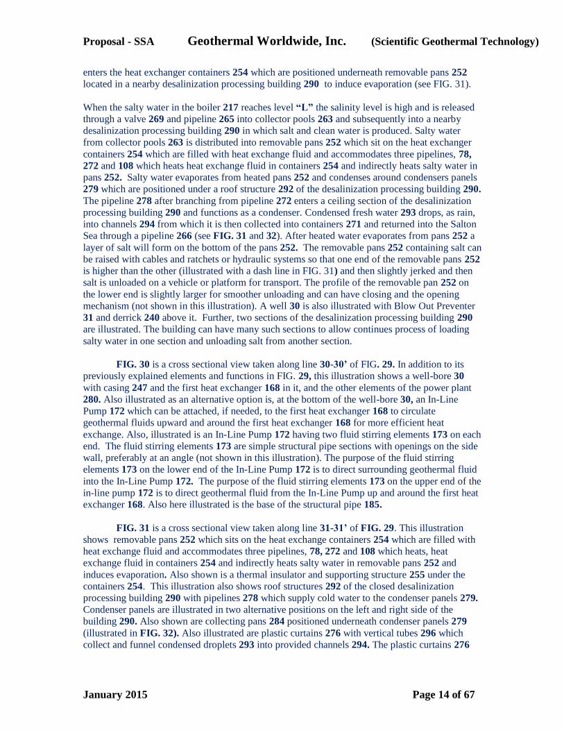
FIG. 30 is a cross sectional view taken along line 30-30’ of FIG. 29. In addition to its
previously explained elements and functions in FIG. 29, this illustration shows a well-bore 30
with casing 247 and the first heat exchanger 168 in it, and the other elements of the power plant
280. Also illustrated as an alternative option is, at the bottom of the well-bore 30, an In-Line
Pump 172 which can be attached, if needed, to the first heat exchanger 168 to circulate
geothermal fluids upward and around the first heat exchanger 168 for more efficient heat
exchange. Also, illustrated is an In-Line Pump 172 having two fluid stirring elements 173 on each
end. The fluid stirring elements 173 are simple structural pipe sections with openings on the side
wall, preferably at an angle (not shown in this illustration). The purpose of the fluid stirring
elements 173 on the lower end of the In-Line Pump 172 is to direct surrounding geothermal fluid
into the In-Line Pump 172. The purpose of the fluid stirring elements 173 on the upper end of the
in-line pump 172 is to direct geothermal fluid from the In-Line Pump up and around the first heat
exchanger 168. Also here illustrated is the base of the structural pipe 185.
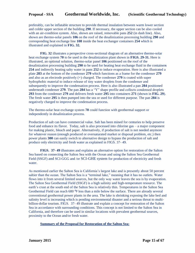
FIG. 31 is a cross sectional view taken along line 31-31’ of FIG. 29. This illustration
shows removable pans 252 which sits on the heat exchange containers 254 which are filled with
heat exchange fluid and accommodates three pipelines, 78, 272 and 108 which heats, heat
exchange fluid in containers 254 and indirectly heats salty water in removable pans 252 and
induces evaporation. Also shown is a thermal insulator and supporting structure 255 under the
containers 254. This illustration also shows roof structures 292 of the closed desalinization
processing building 290 with pipelines 278 which supply cold water to the condenser panels 279.
Condenser panels are illustrated in two alternative positions on the left and right side of the
building 290. Also shown are collecting pans 284 positioned underneath condenser panels 279
(illustrated in FIG. 32). Also illustrated are plastic curtains 276 with vertical tubes 296 which
collect and funnel condensed droplets 293 into provided channels 294. The plastic curtains 276
Proposal - SSA Geothermal Worldwide, Inc. (Scientific Geothermal Technology)
January 2015 Page 15 of 67
preferably, can be inflatable structure to provide thermal insulation between warm lower section
and colder upper section of the building 290. If necessary, the upper section can be also cooled
with an air-condition system. Also, shown are raised, removable pans 252 (in dash line). Also,
shown are thermo-solar panels 106 on the roof of the desalinization processing building 290 and
corresponding heat exchange line 108 inside the heat exchanger containers 254 which is
illustrated and explained in FIG. 32.
FIG. 32 illustrates a perspective cross-sectional diagram of an alternative thermo-solar
heat exchange system 70 to be used in the desalinization plant shown in FIGS. 29-31. Here is
illustrated, an optional solution, thermo-solar panel 106 positioned on the roof of the
desalinization processing building 290 to be used for heating heat exchange fluid in the containers
254 and indirectly heating salty water in pans 252 to induce evaporation. Here is also illustrated a
plate 283 at the bottom of the condenser 279 which functions as a frame for the condenser 279
and also as an electrode positively (+) charged. The condenser 279 is coated with super
hydrophobic material to induce release of tiny water droplets from the condenser and
subsequently to improve the condensation process. Here is also illustrated a pan 284 positioned
underneath condenser 279. The pan 284 has a “Y” shape profile and collects condensed droplets
293 from the condenser 279 and delivers fresh water 295 into containers 271 (shown in FIG. 29).
The fresh water 295 is then pumped into the sea or used for different purpose. The pan 284 is
negatively charged to improve the condensation process.
The thermo-solar heat exchange system 70 could function with geothermal support or
independently in desalinization process.
Production of salt can have commercial value. Salt has been mined for centuries to help preserve
food and enhance its flavor. Today, salt is also processed into chlorine gas – a major component
for making plastic, bleach and paper. Alternatively, if production of salt is not needed anymore
for whatever reason (enough produced or oversaturated market or disposal problem, etc.) then
power plants 300 can easily switch to alternative design to bypass the production of salt and
produce only electricity and fresh water as explained in FIGS. 37- 49.
FIGS. 37- 49 illustrates and explains an alternative option for restoration of the Salton
Sea based on connecting the Salton Sea with the Ocean and using the Salton Sea Geothermal
Field (SSGF) and SCI-GGG and /or SCI-GHE system for production of electricity and fresh
water.
As mentioned earlier the Salton Sea is California’s largest lake and is presently about 50 percent
saltier than the ocean. The Salton Sea is a “terminal lake,” meaning that it has no outlets. Water
flows into it from several limited sources, but the only way water leaves the sea is by evaporation.
The Salton Sea Geothermal Field (SSGF) is a high salinity and high-temperature resource. The
earth’s crust at the south end of the Salton Sea is relatively thin. Temperatures in the Salton Sea
Geothermal Field can reach 680 ⁰F less than a mile below the surface. There are already several
conventional geothermal power plants in the area. The lake is shrinking exposing the lake bed and
salinity level is increasing which is pending environmental disaster and a serious threat to multi-
billion-dollar tourism. FIGS. 37- 49 illustrate and explain a concept for restoration of the Salton
Sea in accordance with surrounding conditions. This concept is not limited to the Salton Sea in
California, and therefore can be used in similar locations with prevalent geothermal sources,
proximity to the Ocean and/or fresh water.
Summary of the Proposal for Restoration of the Salton Sea:
Proposal - SSA Geothermal Worldwide, Inc. (Scientific Geothermal Technology)
January 2015 Page 16 of 67
The objectives of the enclosed Proposal for Restoration of the Salton Sea are:
1. Raising and stabilizing the lake’s waterline level by connecting the Salton Sea with
Pacific coast (Phase I);
2. Preventing further pollution of the lake by building two main dikes forming a central
mass of water and two peripheral reservoirs for containing and treating current inflow and
farmland runoff waters and reusing it and providing wildlife sanctuary (Phase II);
3. The equalizing salinity of the salty terminal lake (Salton Sea) water with salinity of
the oceanic water and subsequently providing conditions for tourism and making Salton Sea a
renewed recreational destination (Phase I & II); and
4. Harnessing prevalent geothermal source of the Salton Sea Geothermal Field (SSGF)
for generation of electricity and production of potable water – both having commercial value
(Phase III, IV & V).
The proposal for restoration of the Salton Sea consists of five Phases:
Phase I – Connecting the Salton Sea with the Ocean (San Diego, Oceanside area) with
several pipelines (inflows and outflows);
Phase II - Building two main dikes - one in northern and one in southern part of the
Salton Sea.
Phase III – Building one power plant using (SCI-GHE) system at one of selected sector;
alternatively, first Power Plant could use binary system to provide electricity during production of
Phase I and pumping system.
Phase IV – Building several more power plants using (SCI-GHE) system - one in each
selected sector; and
Phase V – Continued buildup of additional power plants using (SCI-GHE) system at
each selected sector; this phase (Phase V) can be built rapidly with additional investments or
alternatively at a slower pace by investments from a portion of revenue generated from preceding
power plants.
Phase I:
Phase I consists of building an ocean pipeline system connecting the Salton Sea with
Pacific coast - San Diego or Oceanside area. The pipeline may have preferably 10 pipelines (8
inflow and 2 outflow) following FWY 8 or FWY 10 to Beaumont, then 79, Temecula, etc. or
around the mountains through Riverside or any other preferred corridor. Having Phase I finished
we would be able to pump out high salinity water from the bottom of the Salton Sea and inject it
into the Pacific Ocean and bring Oceanic water into the Salton Sea. High salinity water has a
higher density and has a tendency to accumulate in the bottom of the Salton Sea. By connecting
the Salton Sea with the Ocean we would be able to control the level of the Salton Sea and
equalize (reduce) salinity of the Salton Sea with the salinity of the Ocean. Why San Diego area
and not the Sea of Cortez?
Proposal - SSA Geothermal Worldwide, Inc. (Scientific Geothermal Technology)
January 2015 Page 17 of 67
The Sea of Cortez has stationary water and we may end up exchanging the same fluid.
Pacific coast has strong current and high salinity water from the Salton Sea will disperse into the
vast Ocean without negative effect on marine life. Also, this way we will eliminate “other country
issue”. In some embodiments, the ocean pipeline system may comprise at least three ocean
pipelines fluidly connecting an ocean with a central mass of water in a salty terminal lake, such as
the Salton Sea. Two of the at least three ocean pipelines provide inflow into the salty terminal
lake and one pipeline provides outflow from the salty terminal lake for controlling the lake water
level.
Phase II:
Phase II consists of a building of two dikes - One in northern and one in southern part of
the Salton Sea – providing reservoirs for runoffs water from nearby farmland in which is runoffs
water temporally contained, and if necessary treated, before pumping it back and reusing it for
farmland. An example for the treatment of wastewater can be the Arcata Wastewater Treatment
Plant and Wildlife Sanctuary. It is an innovative sewer management system employed by the city
of Arcata, California. A series of oxidation ponds, treatment wetlands and enhancement marshes
are used to filter sewage waste. Alternatively, water from reservoirs can be pumped into
“outflow” pipeline(s) for dispersing it into vast Pacific Ocean or can be injected into wells for
forming or maintaining geothermal reservoirs for better heat transfer to the heat exchange system.
Benefits of Phase I & II:
1. By saving and restoring the Salton Sea we will continue having a substantial water
surface in our proximity which has a positive effect on our local climate.
2. After several years the Salton Sea will contain mostly oceanic water. By controlling
inflow and outflow at the Salton Sea we can produce a surplus of (now) oceanic water to be used
for feeding geothermal power plants for generation of electricity and potable water.
3. As a renewed recreational destination the Salton Sea area will flourish with tourism. Beaches can operate all year around. It would provide a base for building memorable restaurants,
resorts and waterfront communities.
4. The wildlife sanctuary will thrive and ecosystem will benefit.
Consequences if we don’t restore the Salton Sea:
1. If we don’t restore and save the Salton Sea it will dry out with the exception of one or
two relatively small ponds which will have extremely high salt concentration and will be toxic. A
huge lake bed will be exposed and we would encounter negative effects such as dust storms and
health issues associated with it such as asthma and other respiratory diseases;
2. Already established wildlife will gradually disappear;
3. Real estate value depreciation in nearby areas and subsequently reduction in businesses
and population will occur. In a recent report, the Oakland-based Pacific Institute projected that
without action to address the Salton Sea’s deterioration, the long-term social and economic costs
— in higher health care costs and lower property values, among other costs — could range
Proposal - SSA Geothermal Worldwide, Inc. (Scientific Geothermal Technology)
January 2015 Page 18 of 67
between $29 billion and $70 billion over the next 30 years.
Cost estimate for Phase I & II
This proposal is a preliminary design explaining the feasibility of the concept. The
second stage would require collaboration with potential contractors and would contain more
details, including more detailed cost estimate, which would follow with the final production
design. After consulting with engineers in the pipeline business, I have been informed that range
of cost today of installed pressure pipe of 48-inch diameter in various terrains would be $600 -
$1,000 per linear foot. I used most conservative option $1,000 per linear foot. This is still a rough
cost estimate, a few adjustments still can be made, but at least we have a bulk cost estimate for
evaluating the proposal.
It means that connecting the Salton Sea with Pacific Ocean (San Diego area) distance
about 80 miles (about 20 miles mountain terrain and about 60 miles relatively flat terrain ). It
comes to: 80 miles x 10 pipelines = 800 miles of pipelines could cost about $4.3 billion. To add
several pump stations, several freeway underpasses, and permits - it still might be under $5
billion. I believe that two main dikes (about 15 miles), separating the Salton Sea and several
secondary dikes (another 15 miles), including treatment plants, could cost another billion or two
which would end up to about $7 billion.
To start several power plants on several sectors around the Salton Sea could take another
billion or two. Proposed power plants consist of 24 wellbores and with many projected power
plants we need to implement a new system for drilling faster, deeper and wider wellbores.
The new drilling system is more expensive at this earlier stage because of development cost, but
in the long term it is better and less expensive solution.
It means that we can restore the Salton Sea with less than 10 billion. A portion of the
revenue from those several power plants in several sectors around the Salton Sea can be used for
financing subsequent power plants. This will provide conditions for the private sector to get
involved with more confidence. This process will continue to grow and the future generations
will continue building on it.
In the meantime, by filling central part of the Salton Sea with oceanic water, the private
sector could start developing resorts, beaches, hotels, motels, etc., and start generating revenue
from tourism.
It is important to understand the importance of implementation of this proposal,
especially Phases I & II, for the restoration of the Salton Sea and the ratio of its cost and benefits.
Whatever initial cost to build the Phase I & II is going to be - $4 billion, $5 billion or even $6
billion - it is imperative that we do it because it is the foundation for subsequent phases which
have great potential for generating revenue in hundreds billion of dollars, economic development
and clean environment. The In-Line Pump (illustrated in FIGS. 22 & 23) should be used for two
way pipelines connecting the Salton Sea with Pacific coast because this system requires the least
energy for operation. Each In-Line Pump is an efficient pumping device and would reduce the
final cost of the project. It functions as a generator at downhill flow routes – it generates
electricity, which can be added as a supplement to energy needed for uphill and horizontal flow
routes. We should have at least 3 bidders (contractors) and select one with most affordable price
and best credentials. The Salton Sea Authority should inform local politicians about this proposal
Proposal - SSA Geothermal Worldwide, Inc. (Scientific Geothermal Technology)
January 2015 Page 19 of 67
and should initiate an aggressive effort on state and federal level asking for a grant or long term
loan for implementation of the Phase I & II. As is the case with any new technology, it is
difficult to predict the exact costs for development and implementation of the “Scientific
Geothermal Technology” but because of the unique location, having a source of heat - mantle
plume under the Salton Sea Geothermal Field (SSGF) - and the simplicity of the system, the
revenue generated from harnessing geothermal energy is expected to be in the hundred billions of
dollars in several decades and will continue generating such revenue in the future. Therefore,
whether initial expenses of the project are $9 billion or $17 billion is less relevant in comparison
to long term benefits gained for economy and environment. It is imperative that we find funding
for it.
Another strong point of proving irrelevancy of the initial cost of the project is that in a
recent report, the Oakland-based Pacific Institute projected that without action to address the
Salton Sea’s deterioration, the long-term social and economic costs — in higher health care costs
and lower property values, among other costs — could range between $29 billion and $70 billion
over the next 30 years.
The ratio of cost and benefits of this proposal for restoration of the Salton Sea can be
compared to the ratio of cost and benefits of the Hoover Dam. Although, the Hoover Dam at this
time operates with only 20% capacity because of the drought, it has generated revenue many
times over it’s initial investment and still continue so. Reduction of production capacity is not
expected in the Salton Sea project.
How to pay for Phase I & II?
A substantial portion of the cost for the Phase I & II could be paid in the future from
portion of revenue generated from tourism. Also, a portion of the cost for the Phase I & II could
be paid from the revenue generated from Geothermal Power Plants during and after building up
of Phase V.
Phase III:
Phase III consists of building the first Power Plant at one selected sector, in accordance
with the proposal, using Self Contained In-Ground Heat Exchanger (SCI-GHE) system modified
so to use salty water from the lake to generate electricity and having byproduct fresh water.
Portion of generating revenue from producing electricity and fresh water can be used for building
subsequent power plants of (Phase IV). By having saved the Salton Sea (Phase I & II) we will
have plenty of (now) oceanic water for operating many Power Plants in the surrounding area.
Alternatively, for the first Power Plant (Phase III) we could use binary system to provide
electricity during construction of the (Phase I) and further for pumping fluids through the pipeline
system.
Phase IV:
By having saved the Salton Sea (Phases I & II) and finished building the first Power Plant
(Phase III) using the Self Contained In-Ground Heat Exchanger (SCI-GHE) system we can start
building several additional power Plants – one on each selected sector in accordance with the
proposal;
Proposal - SSA Geothermal Worldwide, Inc. (Scientific Geothermal Technology)
January 2015 Page 20 of 67
Phase V:
Phase V consists of continued buildup of additional Power Plants. By having saved the
Salton Sea (Phase I & II) we will have plenty of ocean water for operating series of Power Plants
using the Self Contained In-Ground Heat Exchanger (SCI-GHE) system modified so to use salty
water from the lake to generate electricity and produce fresh water. By using the Self Contained
In-Ground Heat Exchanger (SCI-GHE) system we are not limited to geothermal reservoirs.
Because of the unique location, having mantle plume under the Salton Sea Geothermal Field
(SSGF), the potential for the profit by harnessing geothermal energy is enormous. This phase
(Phase V) can be built rapidly with additional investments or alternatively at a slower pace of
investments from portion of revenue generated from preceding power plants.
FIGS. 37- 49 illustrates and explains an alternative option for restoration of the Salton
Sea based on connecting the Salton Sea with the Ocean and using the Salton Sea Geothermal
Field (SSGF) and SCI-GGG and /or SCI-GHE system for generation of electricity and production
of fresh water .
This concept is not limited to, the Salton Sea in California, therefore can be used in locations with
similar conditions with prevalent geothermal sources, proximity to the Ocean and/or fresh water.
FIG. 37 is a plain view of a large salty body of water and schematic diagram of pipeline
systems associated with a proposal for restoration of the Salton Sea. Here is illustrated: a plain
view of a large salty body of water 156 with dikes 157 and 158 on northern and southern part of
the lake 156. Here are also shown array of Power Plants 300 on several sectors. Also shown here
is d diagram of pipelines system for exchanging waters from the lake and the ocean using outflow
line 330 and inflow line 350. Here is also shown feeding pipelines 264 for injecting water from
the Salton Sea (lake) 156 into geothermal power plants 300 for generation of electricity. Also,
here are shown pipelines 265 for transport of high salinity water from power plants 300. Here are
also shown freshwater lines 256. The Power plants 300 using Self Contained In-Ground Heat
Exchanger (SCI-GHE) system is modified to use salty water from the lake 156 to generate
electricity and produce fresh water and is explained in more details in FIGS. 41-49.
Two dikes 157 and 158 are positioned on northern and southern side of the lake 156 to form
reservoirs 204 and 206 for separating and collecting runoff waters contaminated with fertilizers
and pesticides from nearby farmland and to prevent further pollution of the lake. Reservoirs 204
and 206 are divided with internal dikes 197 and 198 into smaller sections designed for the
treatment and purification of polluted runoff water. An example for the treatment of wastewater
can be the Arcata Wastewater Treatment Plant and Wildlife Sanctuary. It is an innovative sewer
management system employed by the city of Arcata, California. A series of oxidation ponds,
treatment wetlands and enhancement marshes are used to filter sewage waste.
Polluted water is temporally contained, and if necessary treated, in reservoirs 204 and 206 before
pumped back and reused at nearby farmland trough pipeline 337 and/or 339 (FIG.38). Two
reservoirs 204 and 206 are connected with additional pipeline branches 333 and 334 to the
“outflow” pipeline 330. Alternatively, water from reservoirs 204 and 206 can be pumped into
“outflow” pipeline 330 and dispersed into the vast Pacific Ocean or disposing it into wells and
forming or maintaining geothermal reservoirs for better heat transfer to the heat exchange system
210.
Polluted water is temporally contained, and if necessary treated, in reservoirs 204 and 206 before
Proposal - SSA Geothermal Worldwide, Inc. (Scientific Geothermal Technology)
January 2015 Page 21 of 67
pumped back and reused at nearby farmland trough pipeline 337 and/or 339 (FIG.38). Two
reservoirs 204 and 206 are connected with additional pipeline branches 333 and 334 to the
“outflow” pipeline 330. Alternatively, water from reservoirs 204 and 206 can be pumped into
“outflow” pipeline 330 and dispersed into the vast Pacific Ocean or disposing it into wells and
forming or maintaining geothermal reservoirs for better heat transfer to the heat exchange system
210.
The pump-stations 301 and 302, and inflows pipelines 350 and outflow pipeline 330 can use the
“In-Line Pump” 172 illustrated and described in FIGS. 22 and 23. The IN-LINE PUMP 172 is an
electromotor cylindrical shape and can be inserted as a repetitive segment in the pipeline and has
no length limitation, therefore increasing power to the electromotor imparts added pumping to
circulate fluid at desired speed. The “In-Line Pump” 172 is an efficient pumping device and
would reduce the final cost of the project. It functions as a generator at downhill flow routes – it
generates electricity, which can be added as a supplement to energy needed for uphill and
horizontal flow routes.
The “inflow” pipeline 350 pumps oceanic water and transfers it into the salty body of water (lake)
156. Having at least three pipelines we can exchange high salinity water from the bottom of the
lake 156 with one pipeline and use other two pipelines for bringing oceanic water into the lake
156. By controlling water exchange from the lake and the Ocean we can reduce salinity and
increase water level of the lake and eventually equalize salinity of the lake with oceanic water.
Pacific coast has strong current and dispersed high salinity water will have no negative effect on
marine life.
Here is also illustrated an optional pipeline 258 for transporting fresh water from power plants
300 on the eastern sector directly to canal 316. Here are also illustrated a set of power plants 300
at southern sector taking oceanic water directly from inflows pipelines 350 through pipeline
branch 351 and returning high salinity water into outflow pipeline 330 through pipeline branch
265. Here in southern sector is also shown pipeline 256 for distributing fresh water produced in
power plant 300. Amount of producing fresh water from power plants 300 is approximately half
of the amount of used oceanic water.
FIG. 38 Illustrate a plain view diagram of array of geothermal power plants 300 at a
location east of the Salton Sea with an alternative cooling system using cold water from nearby
canal 316. For clarity and simplicity, here are shown only power plants 300 at only one sector.
Here is illustrated an alternative option for cooling condensers of the power units of the power
plants 300 with closed loop system 310 having inflow line 312 and outflow line 314 by using
relatively cold water from nearby canal 316. Water used for cooling condensers is returned back
without any lost into canal 316 by outflow line 314 for its original intended purpose. This cooling
system is explained in more details in FIG. 44. Here is also illustrated a secondary binary power
unit 355 for additional extraction of heat from outflow cooling line 314, if necessary. The power
unit 355 is explained in more details in FIG. 47.
FIG. 39 Illustrate a plain view diagram of array of geothermal power plants 300 at an
alternative sector southeast of the Salton Sea at location with great geothermal potential. The
functioning concept of power plants 300 in each sector around the Salton Sea is similar and will
be explained in following FIGS. 41-47.
FIG. 40 is a plain view diagram of array of geothermal power plants 300 at the same
location as explained in previous FIG. 39 with a schematic diagram of an alternative cooling

Proposal - SSA Geothermal Worldwide, Inc. (Scientific Geothermal Technology)
January 2015 Page 22 of 67
system 310 as explained in FIG. 38. Here is illustrated an alternative option for cooling
condensers of the power units of the power plants 300 with closed loop system 310 having inflow
line 312 and outflow line 314 by using relatively cold water from nearby canal 317. Water used
for cooling condensers is returned back without any lost in nearby canal 317 by outflow line 314
for its original intended purpose. This cooling system is explained in more details in FIG. 44.
FIG. 41 is a plain view of a schematic diagram of the geothermal power plant 300 with
an array of 24 wells 30. For clarity and simplicity, here is shown only one section of the power
plant 300 with 6 wells and corresponding 6 power units 280. Also, shown here, is heat exchange
systems 210 connecting first heat exchanger 168 inside well 30 and the second heat exchanger
182 inside boiler 217 (illustrated in more details in FIG. 45). Here are also illustrated control
center 200; fresh water pond 274; mineral processing building 290 (optional); railroad tracks 325;
and access road 327; The power units 380 having boiler / evaporator 217; turbines 230; a
condenser 360; and generator 250 are explained in more details in following illustrations. The
other three quarters of the power plant are identical. Desalinization building 290 is shown here as
an optional facility that can be utilized, if needed, for the production of salt and other minerals. A
further embodiment of this invention is that power plants 300 consisting of power unites 380 is a
modular system capable of easy adjustments and reproduction.
It is also an embodiment of this invention that power plant 300 is based on array of multi wells
with relevant power units 380 of medium or smaller sizes which can extract heat from
underground heat source more efficiently and with fewer limitations than in conventional systems
where a single power unit is used and supplied with fluids from natural or man-made
hydrothermal reservoir. By having more wellbores 30 which length (depth) can periodically be
extended and having more corresponding portable multi heat exchangers 168 inside them
increases heat exchanging surface of the wellbores 30 and heat exchanging surfaces of the heat
exchangers 168 altogether. Here presented power units 380 can be portable, easily managed, and
replaced if needed with different capacity power units. Alternatively, several wells with
corresponding heat exchange systems 210 of one section of the power plant 300 can be arranged
to supply heat to one or more power units 380 as illustrated in FIGS. 16-19, 45 and 47.
FIG. 42 illustrates an enlarged schematic diagram of the one section of the geothermal
power plant 300 shown in FIG.41. Here are illustrated power units 380 having boiler / evaporator
217, turbines 230, condenser 360, and generator 250 with a schematic diagram of fluid flow
systems associated with a power plant. Also, shown here, is heat exchange systems 210
connecting first heat exchanger 168 inside well 30 and the second heat exchanger 182 inside
boiler 217 (illustrated in more details in FIG. 45). Here is illustrated pipeline 264 with extended
branch 261 that supply the boiler/evaporator 217 with water from a salty body of water 156 and
pipeline 265 for disposal of high salinity water from boiler/evaporator 217. The pipelines 264
with extended branch 261 and pipeline 265 are aligned together at certain length for the purpose
of exchanging heat from hot pipeline 265 to pipelines 264 and 261 to warm up water entering the
boiler 217. Those pipes pass through heat exchange container 253 similar to the heat exchange
container 254 illustrated and explained in FIG. 32. Also, here is shown a inflow cooling pipeline
273 that takes water from fresh water pond 274, passes through condensers 360, cools it, and
returns through outflow cooling line 275 back into fresh water pond 274. Here is also shown
pipeline 256 that delivers condensed fresh (potable) water from the condenser 360 into fresh
water pond 274.
FIG. 43 illustrates an enlarged schematic diagram of the one section of the geothermal
power plant 300 shown in FIGS.41 and 42 with an alternative cooling system. Here is shown
Proposal - SSA Geothermal Worldwide, Inc. (Scientific Geothermal Technology)
January 2015 Page 23 of 67
condenser 361 which optionally can be cooled with fan and air circulation instead with water.
Alternatively, the boiler 217 can be modified so that fresh water or other working fluids can be
used and recycled.
FIG. 44 illustrates an enlarged schematic diagram of the one section of the geothermal
power plant 300 shown in FIGS.41 with an alternative cooling system. Here are shown all
elements as in FIG. 42 with difference that condenser 360 is cooled with relatively cold water
from nearby canal 316. Here is also shown pipeline 261 that supply the boiler 217 with water
from a salty body of water 156 and pipeline 265 for disposal of high salinity water from
boiler/evaporator 217. A further embodiment of this invention is that additional existing
available sources at location, such is relatively cold water from nearby canal 316, is integrated in
function of the power plant 300. Here are shown inflow line 312 and outflow line 314 of the
closed loop cooling system 310 used for cooling condensers 360. (See FIG. 38). Water used for
cooling condensers 360 is returned back into a canal 316 without any lost. Here is also shown
mineral processing building 290 as an optional facility that can be utilized, if needed, for the
production of salt and other minerals. Also, here is shown water pond 274 for collecting fresh
water from condensers 360 which can be used for agriculture and other applications. Here also is
shown an optional pipeline 257 bypassing water pond 274 and connecting fresh water pipeline
256 from condensers 360 directly to canal 316.
FIG. 45 is a cross sectional view of one power unit 380 of the power plants 300 taken
along line 45-45’ of FIG. 47. This illustration is similar to illustration explained earlier in FIG.
30, with minor modifications made to accommodate additional relevant illustrations. In this
illustration also are shown well-bore 30 with casing 247. Also, here is shown the first heat
exchanger 168 inside well and the second heat exchanger 182 inside boiler/evaporator/distiller
217 with other elements of the power unit 380 - turbines 230, condenser 360, and generator 250.
Here is also shown at the bottom of the well 30, an In-Line Pump 172 which can be attached, if
needed, to the first heat exchanger 168 to circulate geothermal fluids upward and around the first
heat exchanger 168 for more efficient heat exchange. Here is illustrated an In-Line Pump 172
having two fluid stirring elements 173 on each end. The fluid stirring elements 173 are simple
structural pipe sections with openings extending slightly off the center line of the pipeline. The
purpose of the fluid stirring elements 173 on the lower end of the In-Line Pump 172 is to direct
surrounding geothermal fluid into In-Line Pump 172 and purpose of the fluid stirring elements
173 on the upper end of the In-Line Pump 172 is to direct geothermal fluid from the In-Line
Pump 172 up and around the first heat exchanger 168. The first heat exchanger 168 can cool its
surrounding relatively fast therefore circulating geothermal fluid up and down well and around
heat exchanger 168 imparts heat exchange process. Here is also illustrated base of structural pipe
185 which extends to the bottom of the well. Extended the length of the well-bore 30 and
structural pipe 185 provides increased surface of the walls providing more heat to be extracted. A
further embodiment of this invention is that in wells without natural geothermal fluid (dry wells),
we can inject our waste water, for example, high salinity water from boiler 217, to provide the
heat exchange medium.
Here is also shown at least one an In-Line Pump 172 which circulates heat exchange fluid
through closed loop system 210 connecting heat exchangers 168 and 182. As explained in
previous illustrations water from the salty body of water (lake) 156 is injected through pipelines
264 and 261 into boiler 217 at level “H”. Water in boiler 217 is heated through heat exchanger
182. Produced steam from boiler 217 is controlled by valve 288 and turns turbines 230 which is
connected to and spins generator 250 which produces electricity which is then transmitted though
electric grid. Exhausted steam after passing through turbines enters inner piping system 362 of
Proposal - SSA Geothermal Worldwide, Inc. (Scientific Geothermal Technology)
January 2015 Page 24 of 67
the condenser 360. The inner piping system 362 inside condenser 360 is surrounded with
circulating water, which enters through pipeline 312 and exits through pipeline 314. The inner
piping system 362 is a spiral coiled pipe with closed end on top. Several condensers 360 can be
assembled as better illustrated in FIG. 46. “Back Pressure” is a term defining pressure that usually
exists after steam passes though turbine and decreases efficiency of the turbines. A further
embodiment of this invention is that exhausted steam passing through inner piping system 362
reduces and preferably eliminates the “Back Pressure”. The Back Pressure is substantially
reduced or eliminated by increasing length of the inner piping system 362 or adding more
condensers. Also shown here is collected fresh (potable) water under condenser 360 which is
transported through pipe 256. Here is also shown “Blow Out Preventer” 31 and derrick 240 on
dollies 238 which will be explained in more details in subsequent application relevant to drilling.
FIG. 46 is a cross sectional view taken along line 46-46’ of FIGS. 45, 47, and 48. Here
are shown a set of three condensers 360 with inner piping system 362 connected through
distributor chamber 363. The distributor chamber 363 can be equipped with automatic control
valves to control opening and closing of each condenser as needed. Here is also shown inner
piping system 362 inside condenser 360 surrounded with circulating water, which enters
condensers 360 through pipeline 312 and exits through pipeline 314.
FIG. 47 is schematic diagrams of a geothermal power unite 380 of the power plant 300
illustrated in FIG.45 with an alternative secondary power unit aside 355. Here are shown main
elements of the power units 380 – wellbore 30, closed loop system 210, boiler 217, turbines 230,
condenser 360, and generator 250. The boiler 217 is heated trough heat exchanger 182 which is
part of closed loop system 210. Here is also shown condenser 360 with cooling water pipeline
inflow 312 and outflow 314. A further embodiment of this invention is that secondary binary
power unit 355 is connected to the pipeline 72 of the closed loop system 210 on the way out of
boiler 217 for additional extraction of heat and additional generation of electricity. The secondary
power unit 355 consists of two interconnecting binary power units 381 and 382. Binary power
units 381 and 382 have the same elements as power unit 380 with exception boilers are not filled
with salty water from the lake 156 instead; they are filled with working fluid that has a lower
boiling point than water. There are different kinds of working fluids with different boiling points.
The power unit 382 has a lesser capacity than power unit 381 and uses working fluid that has a
lower boiling point than is used in power unit 381. The secondary power unit 355 uses same
cooling water pipeline inflow 312 and outflow 314 as power units 380. The secondary power unit
355 doesn’t produce fresh water. The power unit 355 is also illustrated in FIG. 38 as a part of the
cooling closed loop system 310. The power unit 355 is illustrated here as a secondary binary
power unit, although it can be used as a primary system (also illustrated in FIGS. 16 & 17). The
binary power unit 355 can be used as a primary system, especially if Phase I & II of the proposal
for restoration of the Salton Sea (connecting Salton Sea with Ocean), are for whatever reason,
rejected and Oceanic water cannot be used.
FIGS. 48 is a schematic diagram of an alternative power unite 390 of the geothermal
power plant 300 modified for generation of electricity, production of fresh water and extraction of
minerals. This plan view illustrates an alternative geothermal power unit 390 designed for
locations where subsurface and the geothermal resources therein are rich with minerals. Here are
shown a power unit 390 with main elements - derrick 240, well 30, boiler 217, turbines 230,
condenser 360, generator 250 and processing building 290. The power unit 390 functions
similarly as power unit 380 which is previously explained. Difference in function of the power
unit 390 is that geothermal brine, which is rich in minerals, is excavated through thermally
Proposal - SSA Geothermal Worldwide, Inc. (Scientific Geothermal Technology)
January 2015 Page 25 of 67
insulated excavation line 372 to the surface and injected into heat exchange coil 181 which is
coupled inside boiler 217. Hot geothermal brine travels downhill through heat exchange coil 181
and heats boiler 217 which is filled with salty water from the lake 156 through pipeline 261.
Produced steam from boiler 217 is controlled with valve 288 and turns turbines 230 which is
connected to and spins generator 250 which generates electricity which is then transmitted though
electric grid. A further embodiment of this invention is that geothermal brine is transported from
boiler 217 through brine line 364 to the processing building 290 for extraction of different
minerals.
The function of the processing building 290 is explained in FIGS. 29, 31 and 32 which is
to induce evaporation by heating, removable pans 252 and to induce condensation for production
of the salt and fresh water. Similarly, the same function of the processing building 290 can be
used for extraction of the different minerals such as lithium, magnesium, etc., from geothermal
brine. Different updated processes for extracting minerals can be used in the processing building
290. Processing buildings 290 are strategically positioned in the mid-section of the power plant
300 to accommodate array of 6 wells in each section of the power plant 300. Additional sections
in the processing building 290 can be added, if needed, for syntheses and electrolysis process.
Alternatively, waste material brine, after extraction of minerals in processing building 290, is
returned trough pipeline 374 back into well 30. Also shown here is an alternative pipeline 367
used for high salinity water from boiler 217 level “L”, if needed, to be added to geothermal brine
in pipeline 364 on the way to processing building 290. Also shown here is an alternative pipeline
368 used for high salinity water from boiler 217 level “L” to be injected into well 30 for
replenishing underground geothermal reservoir and sustaining the well 30. Here are also shown
inflow line 312 and outflow line 314 of the closed loop cooling system 310 used for cooling
condenser 360. (See FIG. 38). Here is also shown fresh water line 256. The surfaces of the boiler
and pipeline system can be painted with epoxy bland that resist corrosion in salty water.
Mining on top of the volcano or caldera is not a wise selection for location for excavation of
minerals because at such locations the Earth’s crust is thin and there is a mantle plume below.
Therefore, if mining is conducted it should be at minimal capacity and well should be
replenished. The concept of power unit 390 is introduced here as alternative to main concept of
power unit 380 to be used periodically. There is a movable derrick 240 on a railroad track 325 for
maintaining array of 24 wells at each power plant. The Power unit 390 can be deployed
periodically at each well.
FIG. 49 is a cross sectional view of an alternative power unit 390 taken along line 49’-
49’ of FIG. 48. All elements and function of the power unit 390 is explained in previous FIG. 48.
A further embodiment of this invention is that brine excavation pipeline 372 can be assembled
with a repetitive segment of In-Line Pumps 172. This way will be eliminated excavation
problems which are present in conventional drilling, geothermal and oil industries, especially in
cases where geothermal fluids are deep and geo-pressure is low or doesn’t exist.
This proposal explains a method of how to use unlimited sources of geothermal energy which has
not been used in this way today. This proposal explains how to use the internal heat of our planet
combined with local condition on surface for generation of electricity and production of fresh
water.
This proposal is a feasible conceptual solution for restoration of the Salton Sea containing several
alternative solutions. Final and the best solution can be selected after consultations with the
Salton Sea Authority, local, state, federal and other relevant authorities. The public should be
Proposal - SSA Geothermal Worldwide, Inc. (Scientific Geothermal Technology)
January 2015 Page 26 of 67
informed about this proposal too.
What type of facilities should be built?
The proposal for restoration of the Salton Sea consists of five Phases:
Phase I - Connecting the Salton Sea with the Ocean (San Diego, Oceanside area) with
several pipelines (inflows and outflows);
Phase II - Building two main dikes - One in northern and one in southern part of the
Salton Sea.
Phase III - Building one power plant using (SCI-GHE) system in one of selected sector;
Phase IV - Building several more power plants using (SCI-GHE) system - one in each
selected sector; and
Phase V – Continued buildup of additional power plants using (SCI-GHE) system in
each selected sector;
About Technology:
The proposal for restoration of the Salton Sea implements the Scientific Geothermal
Technology modified so to include local conditions. The Scientific Geothermal Technology (The
Self Contained In-Ground Geothermal Generator; The Self Contained Heat Exchanger; and The
IN-LINE PUMP) consist of several designs and variations complementing each other and/or
operating separately in many different applications in the energy sectors. The In-Line Pump
should be used for two way pipelines connecting the Salton Sea with Pacific coast because this
system requires the least energy for operation.
As a first option for electricity generating unit, to be implemented, for this proposal is the
“Self Contained In-Ground Heat Exchanger” (SCI-GHE) system. It has less production capacity
than the Self Contained In-Ground Geothermal Generator (SCI-GGG) system, but is less
expensive to produce and to implement. Later on when the (SCI-GHE) system starts generating
revenue it can be replaced with (SCI-GGG) system which at this stage requires more investment
and time for full development.
In summary: The function of the “Self Contained In-Ground Heat Exchanger” (SCI-GHE) system
consists of several stages:
1. Extracting heat from prevalent geothermal sources;
2. Transferring heat up to the ground surface through completely closed loop system (no
need for geothermal fluid to be pumped to the surface as is the case with conventional geothermal
systems);
3. Using extracted heat from geothermal sources for generation of electricity for
commercial and residential use; and
4. Producing fresh (potable) water as a byproduct without spending additional energy for

Proposal - SSA Geothermal Worldwide, Inc. (Scientific Geothermal Technology)
January 2015 Page 27 of 67
its production.
Phase III - One proposed power plant consists of 24 wells with 24 modular power units
with the SCI-GHE systems spread peripherally forming a circle with a diameter of about 1,500
feet. Each of the four sections with 6 wells and one mineral processing building can operate
separately as one modular unit. Required space for one power plant is preferably about 2,000’ x
2,000’ (about 90 - 95 acres). The schematic plan of one modular unit of the power plant with the
SCI-GHE system and the desalinization building nearby is illustrated and explained in conceptual
drawings FIGS. 24, 29, 30, 31, 32, and 41-49. Phase I & II are illustrated and explained in FIGS.
37-40. (See accompanying Appendix below).
It is well known that there is an enormous source of energy under our feet whether it is a
few miles underground or on the surface in locations such as Hawaii. The question was, until
now, how to harness it expediently and efficiently?
How many facilities are needed and where should they be located?
After raising and stabilizing lake’s waterline level by connecting the Salton Sea with
Pacific coast (Phase I) and after building two main dikes forming central mass of water and two
peripheral reservoirs for containing and treating farmland runoff waters and providing wildlife
sanctuary (Phase II) - then we can build many power plants using SCI-GHE system for
harnessing prevalent geothermal source of the Salton Sea Geothermal Field (SSGF) for
generation of electricity and production of fresh (potable) water (Phase III, IV & V). The Power
Plant with the SCI-GHE system consists of several modular power units. Many additional power
plants can be built. Location should be at the Salton Sea Geothermal Field (SSGF) around the
southern, eastern and western sides of the lake – preferably mile(s) away from lakes shores. A
modular implementation of the SCI-GHE system creates immediate revenues and allows the
continued buildup of additional modular units. FIGS. 37 - 40 illustrate several proposed locations
(sectors) for implementations of Phase III – V.
What inputs into your system(s) are required and what are the outputs?
In Phase I:
Input is ocean water into the Salton Sea.
The output is high salinity water from the bottom of the Salton Sea to be dispersed into the vast
Ocean preferable a few miles off shore of San Diego area where the ocean current is strong.
In Phases III, IV & V:
There are no inputs, such as fuels for the operation of the proposed Power Plant for generation of
electricity using the SCI-GHE system. For the operation of the proposed Power Plant only input
for production of steam is salty water from the Salton Sea.
The outputs are: generation of electricity and production of potable water and (alternatively) salt.
How do you handle each?
Regarding “Inputs”:
In Phase I - input is oceanic water and will be used for the controlling water-line level of the
Salton Sea and for feeding Power Plants for generation of electricity and production of fresh
(potable) water.
Proposal - SSA Geothermal Worldwide, Inc. (Scientific Geothermal Technology)
January 2015 Page 28 of 67
In Phases III, IV & V - there are no inputs such as fuels for the operation of the proposed Power
Plant to handle. Chemicals such as lubricant or working fluids or heat exchange fluids are part of
the SCI-GHE system which is a closed-loop system and at no time is there any contact with the
environment by the working fluid or the heat exchange fluid therefore it doesn’t pollute the
environment. During regular service those working fluids can be safely maintained and/or
replaced.
Regarding “Outputs”:
In Phase I - high salinity water from the bottom of the Salton Sea is to be dispersed into the vast
Ocean preferable a few miles off shore of San Diego area where the ocean current is strong.
In Phases III, IV & V – Generation of electricity has commercial value. Fresh water as a
byproduct has commercial value. Salt as a byproduct has commercial value. If production of salt
from Salton Sea is determined to have no commercial value or market become saturated, then
production of salt can be stopped and remaining high density salty water from a boiler/distiller
can be injected into the main outflow pipeline connecting the San Diego coast and dispersed into
the vast ocean or can be injected into wells for forming or maintaining geothermal reservoirs for
better heat transfer to the heat exchange system.
.
What are the type, volume and composition of waste streams and what are the
disposal plans?
There are no waste streams during operation of the facility using the SCI-GHE system
other than high density salty water from a boiler/distiller and it is injected into the main outflow
pipeline connecting the San Diego coast and dispersed into the vast ocean (Refer to answer
above).
The volume of high density salty water from a boiler/distiller to be injected into the main outflow
pipeline connecting the San Diego coast and dispersed into vast ocean is approximately half of
the volume of (now) ocean water injected into a boiler/distiller. The other half becomes fresh
(potable) water.
What are your power requirements?
Some power will be required for building the power plant (Phase III) but not after the
facility is in operation because facilities are power plants. Some power will be required for
building the main pipeline (Inflow and Outflow) and for circulating fluids (Phase I). By
implementing the In-Line Pump (Illustrated and described in FIGS. 22 & 23) as a repetitive
segment in the main pipeline (Inflow and Outflow) required power for circulating fluids will be
minimized because presented In-Line Pump in downhill route can function as a generator and
generates electricity which can be used to supplement the In-Line Pump in horizontal and uphill
route. Since the surface of the Salon Sea is 230 feet below sea level and we use 8 pipelines as
inflow and 2 pipelines as outflow, some electricity can be generated in that process.
How will your system respond, or design change, if inflows to the Sea are reduced?
The objectives of the enclosed concept for restoration of the Salton Sea are:
1. Raising and stabilizing the lake’s waterline level by connecting the Salton Sea with
Proposal - SSA Geothermal Worldwide, Inc. (Scientific Geothermal Technology)
January 2015 Page 29 of 67
Pacific coast (Phase I);
2. Preventing further pollution of the lake by building two main dikes forming a central
mass of water and two peripheral reservoirs for containing and treating farmland runoff waters
and providing wildlife sanctuary (Phase II);
3. The equalizing salinity of the Salton Sea with the salinity of the Oceanic water and
subsequently providing conditions for tourism and making Salton Sea a renewed recreational
destination (Phase I & II); and
4. Harnessing prevalent geothermal source of the Salton Sea Geothermal Field (SSGF)
for generation of electricity and production of fresh water – both having commercial value (Phase
III, IV & V).
It would be unfortunate if raising and stabilizing the lake’s waterline level by connecting
the Salton Sea with Pacific coast (Phase I) is not implemented because it is foundation for
additional phases which generate electricity, produce potable water and revenue. Assuming that
the Salton Sea Authority will recognize the importance of this proposal for our community,
economy and environment, it is imperative that the Salton Sea Authority inform everyone that has
potential and power to voice and do its best on local, state and federal level in providing funding
for implementation of this proposal, especially Phases I & II. In the worst case if the Salton Sea
Authority, for whatever reason, fail to recognize importance of this proposal and are unable to
voice message and organize proper funding campaign for this proposal for the restoration of the
Salton Sea on local, state and federal level then presented power plants with the SCI-GHE system
can be slightly modified to function solely as binary power units to generate only electricity. In
this worst case, the number of power plants would be limited and fresh water wouldn’t be
produced and the lake and tourism as economic contributors would not prevail.
Many of the proposals we receive are for water treatment technologies that have
been used in ecosystems or ponds that are 1% or less the size of the Salton Sea; scale
your system appropriately to meet the needs identified under Section 2, Problem
Definition. Please include an estimated project schedule that includes planning,
design and construction durations.
The proposal for restoration of the Salton Sea consists of five Phases:
Phase I – Connecting the Salton Sea with the Ocean (San Diego, Oceanside area) with
several pipelines (inflows and outflows);
Phase II - Building two main dikes - One at northern and one at southern part of the Salton
Sea.
Phase III – Building one power plant using (SCI-GHE) system at one of selected sector;
Phase IV – Building several more power plants using (SCI-GHE) system - one in each
selected sector; and
Phase V – Continued buildup of additional power plants using (SCI-GHE) system at each
selected sector;
Proposal - SSA Geothermal Worldwide, Inc. (Scientific Geothermal Technology)
January 2015 Page 30 of 67
The above question in this section is based on having in mind water treatment technologies.
The Phase II of this proposal covers concept of this issue. Phase II consists of building two main
dikes forming a central mass of water and two peripheral reservoirs - one at northern and one at
southern part of the Salton Sea – for containing and treating inflow and runoff water from nearby
farmland before pumping it back and reusing it for farmland and providing wildlife sanctuary.
Having a central mass of water to be replaced with oceanic water (Phase I) and having two
reservoirs - one at northern and one at southern part of the Salton Sea - for treatment of inflow
and farmland runoff waters drastically reduces the volume of the water to be treated.
An example for the treatment of wastewater can be the Arcata Wastewater Treatment Plant
and Wildlife Sanctuary. It is an innovative sewer management system employed by the city of
Arcata, California. A series of oxidation ponds, treatment wetlands and enhancement marshes are
used to filter sewage waste.
Preliminary design and scale of the two main dike systems forming a central mass of water
and two peripheral reservoirs for containing and treating inflow and farmland runoff waters
consist of several smaller treatment ponds are illustrated in FIGS. 37 & 38.
It is important to mention again that treatment of inflow and farmland runoff waters is just
one phase (Phase II) of the proposal and necessary part of the whole project.
Work on Phases I, II and III can start at the same time. Phase III consists of building one
power plant using (SCI-GHE) system at one of selected sector. The proposed power plant is a
modular power unit. Many additional power plants can be built. Just for understanding the
concept the schematic plan of one modular unit of the power plant with the SCI-GHE system is
illustrated in conceptual drawings FIGS. 41 - 47 (See accompanying Appendix below).
This proposal is a preliminary presentation of the function of the system. If there is a
community effort to restore the Salton Sea and a budget provided for it, then final design and
planning, including development of a new drilling system which will speed up the process and in
the long term reduce the final cost of the whole project, could be accomplished in approximately
12 months. Construction of the first modular power unit with 6 wellbores could be accomplished
in around 18-24 months. Completion of the first power plant with an additional 18 wellbores
could be accomplished in around 18-24 months. As construction of the first power plant
progresses and with experience gathered from the first modular unit, we could start forming
additional teams and start building new power plants without waiting for completion of the first
power plant. In the following decades, many power plants could be built in the Salton Sea Geothermal Field (SSGF). The Salton Sea Geothermal Field (SSGF) has a potential to supply
electricity to California and neighboring states. Implementation of this proposal will be a
continuing process in the right direction and future generation can continue building on it.
4. Other Applications
Please address the following questions:
Where has this technology or process been applied and what problem was it
“solving”?
Proposed methodology has not been demonstrated yet, however, the Scientific Geothermal
Technology uses proven technologies in unique combinations. It is not difficult to understand and
evaluate the concept. I am using this opportunity for restoration of the Salton Sea to introduce the
Proposal - SSA Geothermal Worldwide, Inc. (Scientific Geothermal Technology)
January 2015 Page 31 of 67
SCI-GHE system modified so to generate electricity and produce fresh (potable) water from a
salty body of water in area prevalent with geothermal sources.
How successful was it?
The "Scientific Geothermal Technology” is a new methodology for harnessing geothermal
energy and has not been used in the industry yet, but it is a relatively simple system, especially
the SCI-GHE system which is modified for this application.
Can the efficacy of the solution be verified independently?
Any objective person with a basic understanding of mechanical engineering and
thermodynamics would be able to evaluate the process. The main attribute of my concept is the
simplicity of it and the necessity for it.
If so, by whom (please provide contact information)?
Note that the Salton Sea Reclamation Act of 1998 requires us to consider “proven”
technologies; consequently, such documentation of your solution’s application elsewhere is
important.
The “Scientific Geothermal Technology” uses proven technologies in unique combinations
- however, minor adjustments and modifications are not difficult to accomplish. The “Scientific
Geothermal Technology” consists of proven technologies configured so as to function in confined
spaces such is a wellbore.
5. Cost Estimate
Provide a cost estimate of building your solution at the Salton Sea (capital costs). Also
provide an annual estimate of operations, maintenance, energy and replacement costs
(OME&R). Describe your proposed financing strategies and any aspects of your system(s)
that subsidize the cost or provide a profit.
This proposal is a preliminary design explaining the feasibility of the concept. The
second stage would require collaboration with potential contractors and would contain more
details, including more detailed cost estimate, which would follow with the final production
design. After consulting with engineers in the pipeline business, I have been informed that range
of cost today of installed pressure pipe of 48-inch diameter in various terrains would be $600 -
$1,000 per linear foot. I used most conservative option $1,000 per linear foot. This is still a rough
cost estimate, a few adjustments still can be made, but at least we have a bulk cost estimate for
evaluating the proposal.
It means that connecting the Salton Sea with Pacific Ocean (San Diego area) distance
about 80 miles (about 20 miles mountain terrain and about 60 miles relatively flat terrain ) comes
to: 80 miles x 10 pipelines = 800 miles of pipelines could cost about $4.3 billion. To add several
pump stations, several freeway underpasses, and permits - it still might be under $5 billion. I
believe that two main dikes (about 15 miles), separating the Salton Sea and several secondary
dikes (another 15 miles), including treatment plants, could cost another billion or two which
would end up to about $7 billion.
To start several power plants on several sectors around the Salton Sea could take another

Proposal - SSA Geothermal Worldwide, Inc. (Scientific Geothermal Technology)
January 2015 Page 32 of 67
billion or two. Proposed power plants consist of 24 wellbores and with many projected power
plants we need to implement a new system for drilling faster, deeper and wider wellbores.
The new drilling system is more expensive at this earlier stage because of development cost, but
in the long term it is better and less expensive solution.
It means that we can restore the Salton Sea with less than $10 billion. A portion of the
revenue from those several power plants in several sectors around the Salton Sea can be used for
financing subsequent power plants. This will provide conditions for the private sector to get
involved with more confidence. This process will continue to grow and the future generations
will continue building on it.
In the meantime, by filling central part of the Salton Sea with oceanic water, the private
sector could start developing resorts, beaches, hotels, motels, etc., and start generating revenue
from tourism.
It is important to understand the importance of implementation of this proposal,
especially Phases I & II, for the restoration of the Salton Sea and the ratio of its cost and benefits.
Whatever initial cost to build the Phase I & II is going to be - $4 billion, $5 billion or even $6
billion - it is imperative that we do it because it is the foundation for subsequent phases which
have great potential for generating revenue in hundreds billion of dollars, economic development
and clean environment. The In-Line Pump (illustrated in FIGS. 22 & 23) should be used for two
way pipelines connecting the Salton Sea with Pacific coast because this system requires the least
energy for operation. Each In-Line Pump is an efficient pumping device and would reduce the
final cost of the project. It functions as a generator at downhill flow routes – it generates
electricity, which can be added as a supplement to energy needed for uphill and horizontal flow
routes. We should have at least 3 bidders (contractors) and select one with most affordable price
and best credentials. The Salton Sea Authority should inform local politicians about this proposal
and should initiate an aggressive effort on state and federal level asking for a grant or long term
loan for implementation of the Phase I & II. As is the case with any new technology, it is
difficult to predict the exact costs for development and implementation of the “Scientific
Geothermal Technology” but because of the unique location, having a source of heat - mantle
plume under the Salton Sea Geothermal Field (SSGF) - and the simplicity of the system, the
revenue generated from harnessing geothermal energy is expected to be in the hundred billions of
dollars in several decades and will continue generating such revenue in the future. Therefore,
whether initial expenses of the project are $9 billion or $17 billion is less relevant in comparison
to long term benefits gained for economy and environment. It is imperative that we find funding
for it.
Another strong point of proving irrelevancy of the initial cost of the project is that in a
recent report, the Oakland-based Pacific Institute projected that without action to address the
Salton Sea’s deterioration, the long-term social and economic costs — in higher health care costs
and lower property values, among other costs — could range between $29 billion and $70 billion
over the next 30 years.
The ratio of cost and benefits of this proposal for restoration of the Salton Sea can be
compared to the ratio of cost and benefits of the Hoover Dam. Although, the Hoover Dam at this
time operates with only 20% capacity because of the drought, it has generated revenue many
times it’s initial investment and still continue so. Reduction of production capacity is not
expected in the Salton Sea project.
Proposal - SSA Geothermal Worldwide, Inc. (Scientific Geothermal Technology)
January 2015 Page 33 of 67
This proposal is a conceptual solution for restoration of the Salton Sea containing several
alternative solutions. Final and the best solution can be selected after consultations with the
Salton Sea Authority, local, state, federal and other relevant authorities. For a more detailed
presentation and cost estimate more consultations with the Salton Sea Authority are needed about
willingness, commitment, intensity of startup, and the budget.
I would like to emphasize that the cost for implementing the “Scientific Geothermal
Technology” (especially SCI-GHE system), instead of conventional technology in construction of
new power plants would be less expensive. Power plants implementing the “Scientific
Geothermal Technology” will be dealing with fewer constraints and less maintenance expenses
resulting in higher return on investment.
It is self evident that the SCI-GGG and/or SCI-GHE system will outperform any
conventional geothermal power plant at the same location. How? – Because "Scientific
Geothermal Technology” uses several completely closed loop systems and only absorbs heat
from the heat source. It neither injects fluids into the ground, nor pumps up geothermal fluids on
the ground surface. Ground fluids do not pass through the equipment.
Money shouldn’t be an issue in this case. We are talking about eco-friendly energy
solution for our current and future generations. We are talking about preventing further build up
of greenhouse gases in the atmosphere and preserving our ecosystem and existence of our planet
as we know it. We are talking about saving hundred billions of dollars, which we spend every
year on imported oil. We are talking about new technology that our economy desperately needs.
We are talking about the beginning of a new age in human history.
6. Self-Evaluation
Please address the following questions:
Is your proposal similar to one found in the referenced “Salton Sea
Alternative Evaluation Final Report, 9/97 or Salton Sea Restoration Program
Preferred Alternative Report and Funding Plan, 5/07”?
I am the author of the new methodology for harnessing efficiently geothermal energy which
I have modified to accommodate local conditions of the Salton Sea. It is a breakthrough
technology dealing with clean energy and environment. I have issued several patents and several
patent pending applications relevant to harnessing geothermal energy and a proposal for the
restoration of the Salton Sea with official priority date starting April 7, 2007.
My proposal for the restoration of the Salton Sea is not just about my geothermal process
for generating electricity from hot rocks deep underground. It is a comprehensive concept that
deals with: 1. How to gain a substantial amount of water from existing sources for farmland; 2.
How to bring oceanic water from San Diego area and produce electricity during that process; 3.
How to exchange high salinity water, which has a tendency to accumulate at the bottom of the
lake; 4. How to provide diversified wildlife sanctuary; and 5. How to produce potable water from
ocean water without additional expenses for it.
I have seen quite a few proposals in last 30 years. Proposals such as connecting the Salton
Sea with the Sea of Cortez with canal(s), or tunnel(s), or connecting the Salton Sea with the
Pacific Ocean with a pipeline, etc. Most of those proposals are not neither feasible nor
economical. The prevailing argument against them always was/is: “You want to bring more salt
in already excessively salty lake – what are you going to do with salt?” etc. Also, the prevailing
Proposal - SSA Geothermal Worldwide, Inc. (Scientific Geothermal Technology)
January 2015 Page 34 of 67
argument against it always was/is: “Who is going to pay for water circulation?”, etc. Those
arguments have merit.
Also, recently someone proposed desalinization plant in Mexico (near the Sea of Cortez)
and to bring that fresh water into the Salton Sea. The desalinization process, whether it is reverse
osmosis or other process, is an expensive process. In the “reverse osmosis” process, there are
filters to be changed regularly; needs substantial amount of electricity, etc. - who is going to pay
for it, especially if the facility is in Mexico? Also, there is an obstacle - dealing with “other
country issues”.
My proposal is the only proposal that deals with and successfully solves all those problems
and provides conditions for economic prosperity and clean environment.
The objectives of the enclosed Proposal for Restoration of the Salton Sea are:
1. Raising and stabilizing the lake’s waterline level by connecting the Salton Sea with
Pacific coast (Phase I);
2. Preventing further pollution of the lake by building two main dikes forming a central
mass of water and two peripheral reservoirs for containing and treating current inflow and
farmland runoff waters and providing wildlife sanctuary (Phase II); By separating the lake in
three sections, I am providing about 1,000,000 acre/feet/per year (all current inflow – whatever
exact number is these days) water to be available for farmland and/or refilling depleted aquifer
which otherwise would be lost.
3. The equalizing salinity of the salty terminal lake (Salton Sea) water with salinity of
the oceanic water and subsequently providing conditions for tourism and making Salton Sea a
renewed recreational destination (Phase I & II); and
4. Harnessing prevalent geothermal source of the Salton Sea Geothermal Field (SSGF)
for generation of electricity and production of fresh (potable) water – both having commercial
value (Phase III, IV & V).
If so and rejected therein, why should your proposal be considered now?
I submitted a conceptual proposal to the Salton Sea Authority (SSA) in January 12, 2014. I had
met with four members of the SSA’s Technical Advisory Committee on May 14, 2014, (Mr.
Roger Shintaku, General Manager; Mr. Bruce Wilcox, Imperial Irrigation District, Agricultural
Water Manager; Mr. Daniel E. Farris, PE, Director of Operations, and Mr. Andy Schlange) on
May 14, 2014, at which I also discussed FIGS. 37 & 41. After a short presentation (time imposed
to only several minutes) my impression was that members liked my concept. Since that time I
didn’t hear officially from the Salton Sea Authority. In the meantime, I am submitting an
addition with several more drawings elaborating more on the main concept and most recent
information obtained about cost estimate which was lacking in the previous proposal.
My proposal is unique and should be considered very seriously because it provides
benefits in many sectors: It provides a feasible solution for restoring the Salton Sea; It provides
conditions for developing truism; It provides a substantial amount of water to be available for
farmland and/or refilling depleted aquifer which otherwise would be lost; It generates electricity
with no pollution; and it provides additional fresh (potable) water. All of those beneficial sectors
Proposal - SSA Geothermal Worldwide, Inc. (Scientific Geothermal Technology)
January 2015 Page 35 of 67
will generate revenue of hundreds billion dollars in a few decades and will continue generating
profits in the future with minimal maintenance expenses. This method is self sustained,
environmentally friendly and has great commercial potential.
How quickly will your system “fix” the problem identified (show calculations)?
Presented proposal for restoration of the Salton Sea consist of several phases. Phase I
(connecting the Salton Sea with Ocean) and Phase II (building dikes and ponds for treating inflow
and runoff waters) are most expensive and most important components for saving the Salton Sea.
Phases I & II provides a foundation for additional Phases III, IV, and V (Power Plants) which are
main revenue generating components. Power Plants consist of a modular Power Units. How
quickly we can “fix” the problem depends on the budget and how aggressively we approach the
implementation of this proposal. A modular implementation of the “Scientific Geothermal
Technology” creates immediate revenues and allows the continued buildup of additional modular
units. This will be a continuing process in the right direction and future generation will continue
building on it.
What indicators in/at the Sea should be used to measure your system’s performance
(i.e. how will we know that it is working)?
My proposal consists of several phases which are complimentary. Indicators to measure
system performance would be obvious and visible: It would be raising the water level of the lake;
Reduction salinity of the lake; Substantial increase of water to be available for farmland and/or
refilling depleted aquifer; Generation of electrical power, the production of fresh (potable) water.
Those factors can be measured every day on site. My concept uses prevalent geothermal energy
from the Salton Sea Geothermal Field (SSGF) to generate electricity without polluting the
environment and produces fresh (potable) water. It doesn’t take excessive expertise for someone
to realize that this concept is the way to go forward and in the interest to all of us. How effective
my system will be it depends on the budget, intensity of startup and a number of power plants we
build.
Generally, what positive and negative environmental impacts will your project have?
Positive environmental impacts are:
1. Raising and stabilizing the lake’s water-line level and subsequently preventing lake
shrinkage and lake’s bed exposure which is pending environmental disaster;
2. Desalinization of the Salton Sea and subsequently reviving depleting ecosystem;
3. Preventing further pollution of the lake and treating farmland runoff waters and
providing wildlife sanctuary;
4. The production of fresh (potable) water.
My proposal will not have negative environmental impacts.
How would you offset the negative impacts?
There are no negative impacts.

Proposal - SSA Geothermal Worldwide, Inc. (Scientific Geothermal Technology)
January 2015 Page 36 of 67
APPENDIX
Boiler
Turbine
Converter
Generator
Condenser distributor
SCI-GGG Apparatus
GEOTHERMAL WORLDWIDE, INC.
The SCI-GGG system uses several completely
closed loop systems and generates electricity
down at the heat source and transmits it up to
the ground level by means of electrical cables.
The SCI-GGG system consist of:
• A BOILER;
• A TURBINE;
• A CONVERTER;
• A GENERATOR;
• A CONDENSER DISTRIBUTOR;
• CONDENSER and COOLING system
(not illustrated here); and
• CABLES
Cables
The “Self Contained In-Ground Geothermal Generator“ (SCI-GGG) system
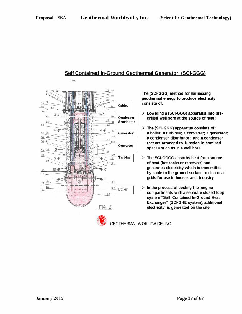
Proposal - SSA Geothermal Worldwide, Inc. (Scientific Geothermal Technology)
January 2015 Page 37 of 67
Boiler
Turbine
Converter
Generator
Condenser distributor
Cables
GEOTHERMAL WORLDWIDE, INC.
Self Contained In-Ground Geothermal Generator (SCI-GGG)
The (SCI-GGG) method for harnessing
geothermal energy to produce electricity
consists of:
Lowering a (SCI-GGG) apparatus into pre-
drilled well bore at the source of heat;
The (SCI-GGG) apparatus consists of:
a boiler; a turbines; a converter; a generator;
a condenser distributor; and a condenser
that are arranged to function in confined
spaces such as in a well bore.
The SCI-GGGG absorbs heat from source
of heat (hot rocks or reservoir) and
generates electricity which is transmitted
by cable to the ground surface to electrical
grids for use in houses and industry.
In the process of cooling the engine
compartments with a separate closed loop
system “Self Contained In-Ground Heat
Exchanger” (SCI-GHE system), additional
electricity is generated on the site.
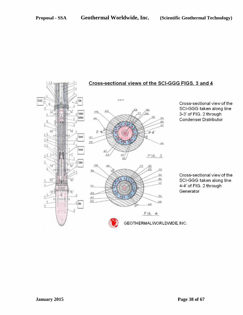
Proposal - SSA Geothermal Worldwide, Inc. (Scientific Geothermal Technology)
January 2015 Page 38 of 67
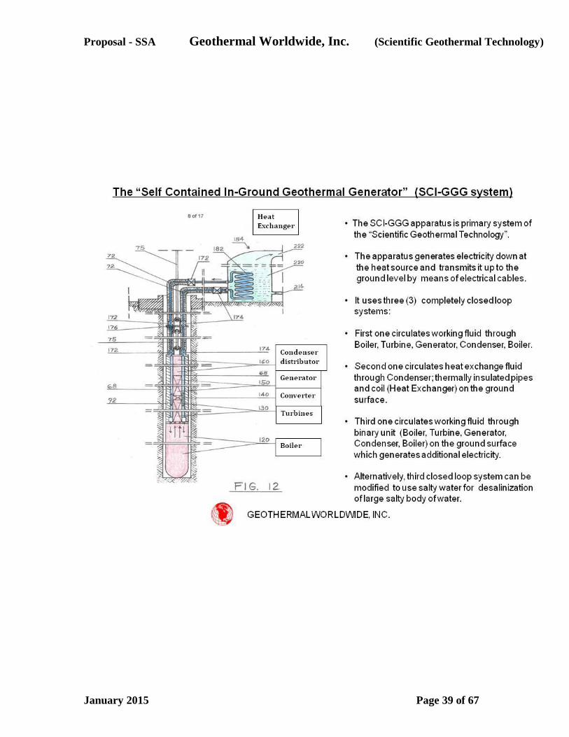
Proposal - SSA Geothermal Worldwide, Inc. (Scientific Geothermal Technology)
January 2015 Page 39 of 67
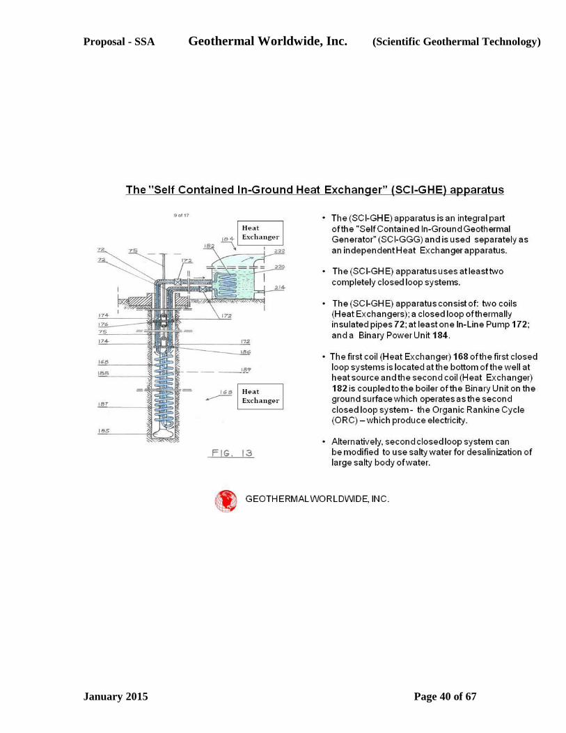
Proposal - SSA Geothermal Worldwide, Inc. (Scientific Geothermal Technology)
January 2015 Page 40 of 67
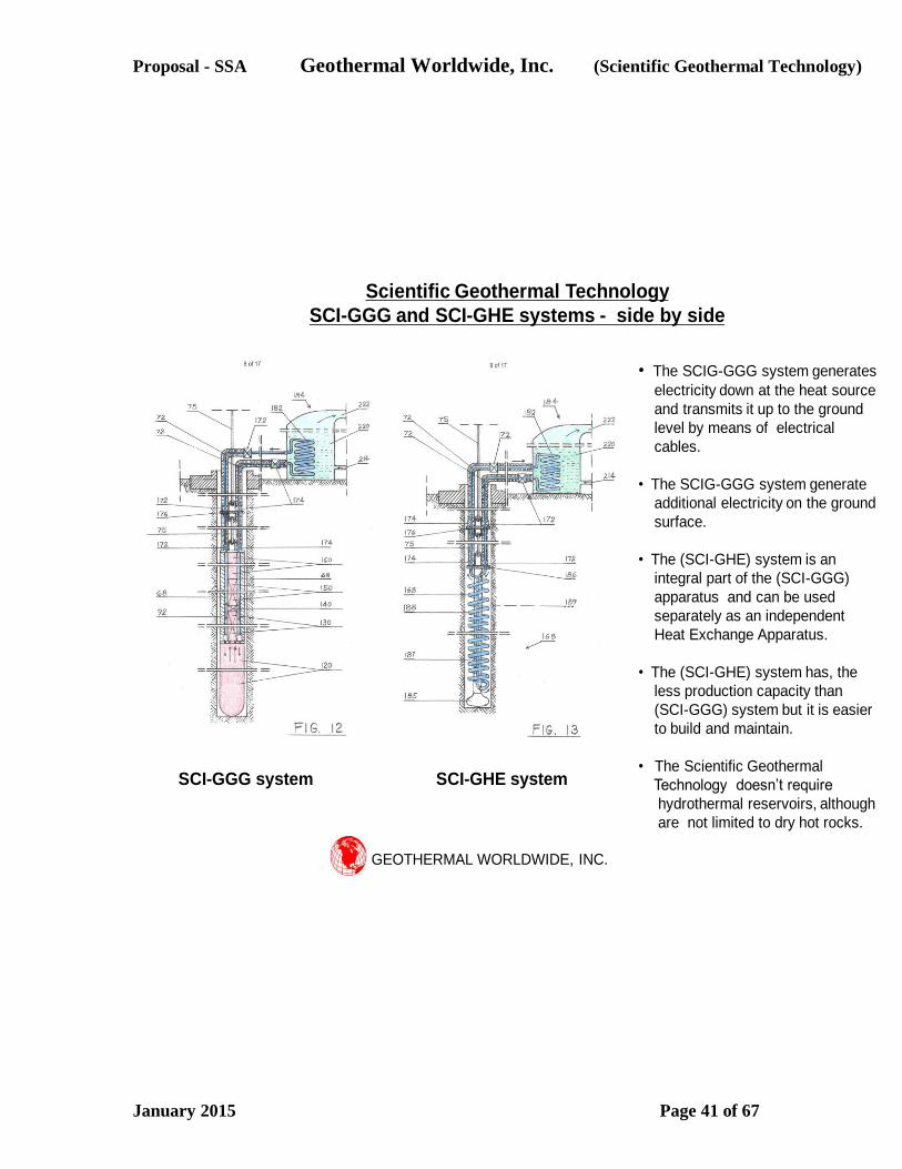
Proposal - SSA Geothermal Worldwide, Inc. (Scientific Geothermal Technology)
January 2015 Page 41 of 67
GEOTHERMAL WORLDWIDE, INC.
SCI-GGG system SCI-GHE system
• The SCIG-GGG system generates
electricity down at the heat source
and transmits it up to the ground
level by means of electrical
cables.
• The SCIG-GGG system generate
additional electricity on the ground
surface.
• The (SCI-GHE) system is an
integral part of the (SCI-GGG)
apparatus and can be used
separately as an independent
Heat Exchange Apparatus.
• The (SCI-GHE) system has, the
less production capacity than
(SCI-GGG) system but it is easier
to build and maintain.
• The Scientific Geothermal
Technology doesn’t require
hydrothermal reservoirs, although
are not limited to dry hot rocks.
Scientific Geothermal Technology
SCI-GGG and SCI-GHE systems - side by side
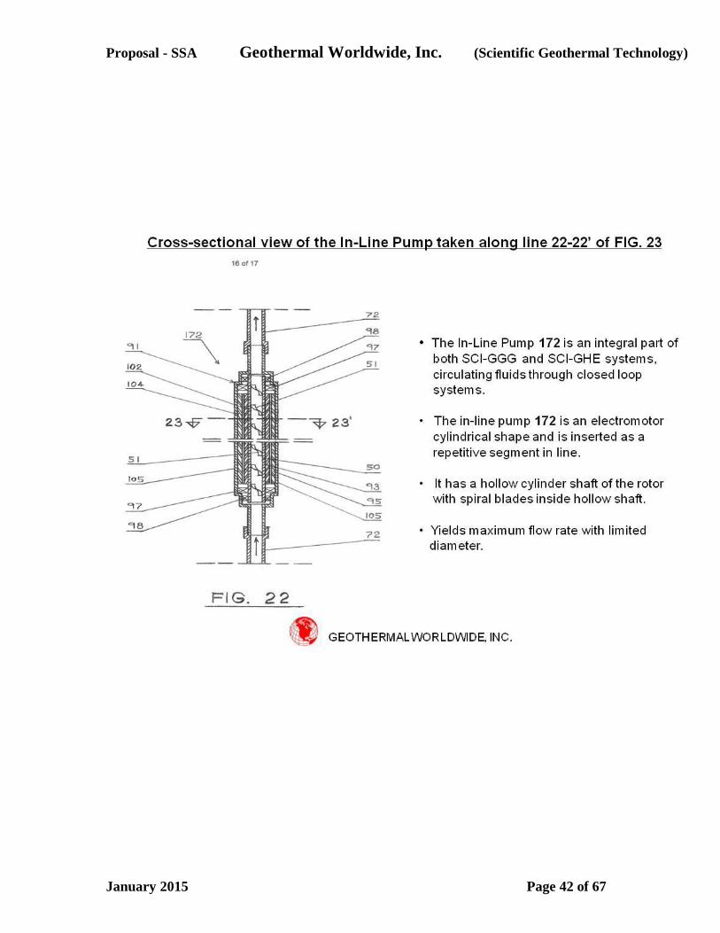
Proposal - SSA Geothermal Worldwide, Inc. (Scientific Geothermal Technology)
January 2015 Page 42 of 67

Proposal - SSA Geothermal Worldwide, Inc. (Scientific Geothermal Technology)
January 2015 Page 43 of 67
GEOTHERMAL WORLDWIDE, INC.
• Alternatively, the In-Line Pump 172 can be
inserted as a repetitive segment of a raiser
pipe for pumping fluids up to the ground
surface from reservoirs in which geo-
pressure is low.
• Also, it can be used in cross-country
pipeline for oil, gas, water, etc. as a repetitive
segment.
• In downhill route it can function as a
generator and generates electricity, which can
be used to supplement In-Line Pump in
horizontal and uphill route.
Cross-sectional view of the In-Line Pump taken along line 23-23’ of FIG. 22

Proposal - SSA Geothermal Worldwide, Inc. (Scientific Geothermal Technology)
January 2015 Page 44 of 67
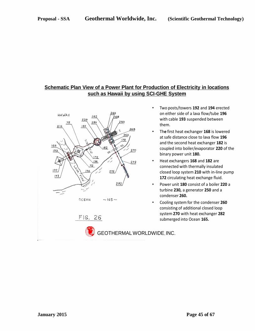
Proposal - SSA Geothermal Worldwide, Inc. (Scientific Geothermal Technology)
January 2015 Page 45 of 67
• Two posts/towers 192 and 194 erected on either side of a lava flow/tube 196with cable 193 suspended between them.
• The first heat exchanger 168 is lowered at safe distance close to lava flow 196 and the second heat exchanger 182 is coupled into boiler/evaporator 220 of the binary power unit 180.
• Heat exchangers 168 and 182 are connected with thermally insulated closed loop system 210 with in-line pump 172 circulating heat exchange fluid.
• Power unit 180 consist of a boiler 220 a turbine 230, a generator 250 and a condenser 260.
• Cooling system for the condenser 260 consisting of additional closed loop system 270 with heat exchanger 282 submerged into Ocean 165.
GEOTHERMAL WORLDWIDE, INC.
Schematic Plan View of a Power Plant for Production of Electricity in locations
such as Hawaii by using SCI-GHE System
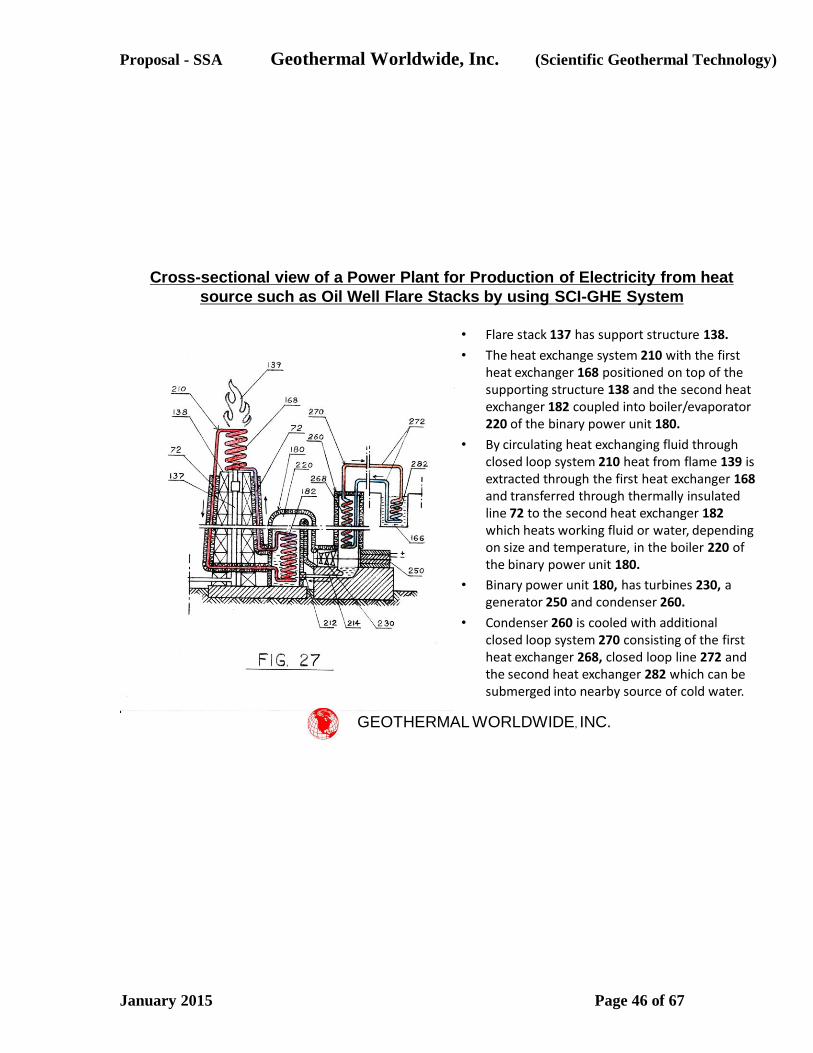
Proposal - SSA Geothermal Worldwide, Inc. (Scientific Geothermal Technology)
January 2015 Page 46 of 67
• Flare stack 137 has support structure 138.
• The heat exchange system 210 with the first heat exchanger 168 positioned on top of the supporting structure 138 and the second heat exchanger 182 coupled into boiler/evaporator 220 of the binary power unit 180.
• By circulating heat exchanging fluid through closed loop system 210 heat from flame 139 is extracted through the first heat exchanger 168 and transferred through thermally insulated line 72 to the second heat exchanger 182 which heats working fluid or water, depending on size and temperature, in the boiler 220 of the binary power unit 180.
• Binary power unit 180, has turbines 230, a generator 250 and condenser 260.
• Condenser 260 is cooled with additional closed loop system 270 consisting of the first heat exchanger 268, closed loop line 272 and the second heat exchanger 282 which can be submerged into nearby source of cold water.
Cross-sectional view of a Power Plant for Production of Electricity from heat
source such as Oil Well Flare Stacks by using SCI-GHE System
GEOTHERMAL WORLDWIDE, INC.
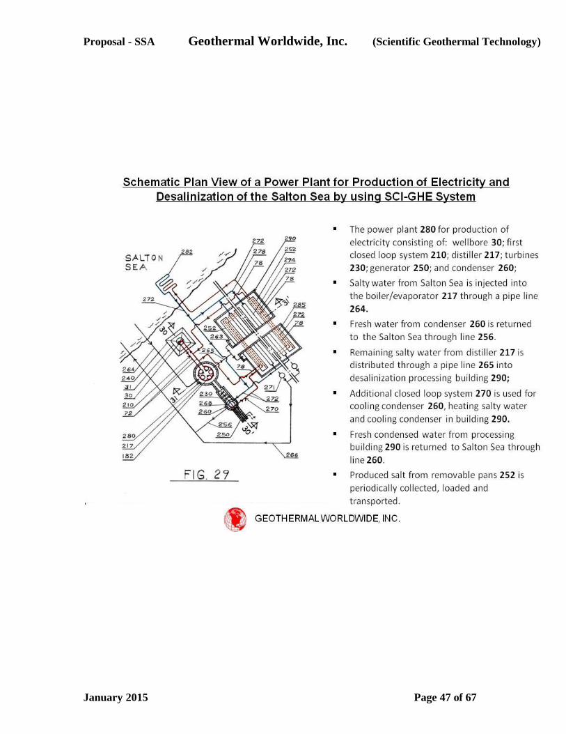
Proposal - SSA Geothermal Worldwide, Inc. (Scientific Geothermal Technology)
January 2015 Page 47 of 67
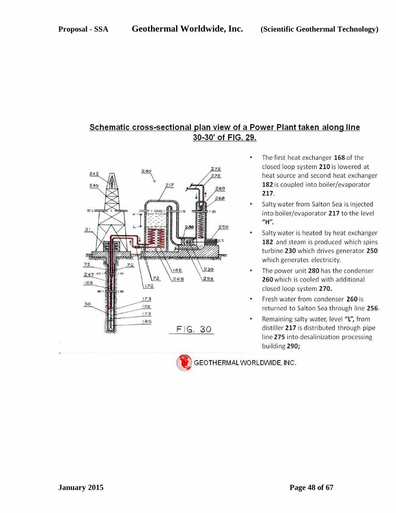
Proposal - SSA Geothermal Worldwide, Inc. (Scientific Geothermal Technology)
January 2015 Page 48 of 67
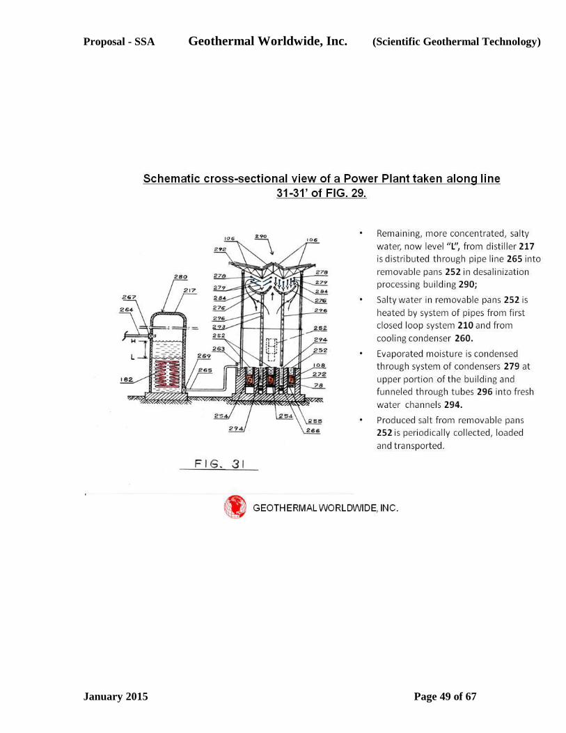
Proposal - SSA Geothermal Worldwide, Inc. (Scientific Geothermal Technology)
January 2015 Page 49 of 67

Proposal - SSA Geothermal Worldwide, Inc. (Scientific Geothermal Technology)
January 2015 Page 50 of 67
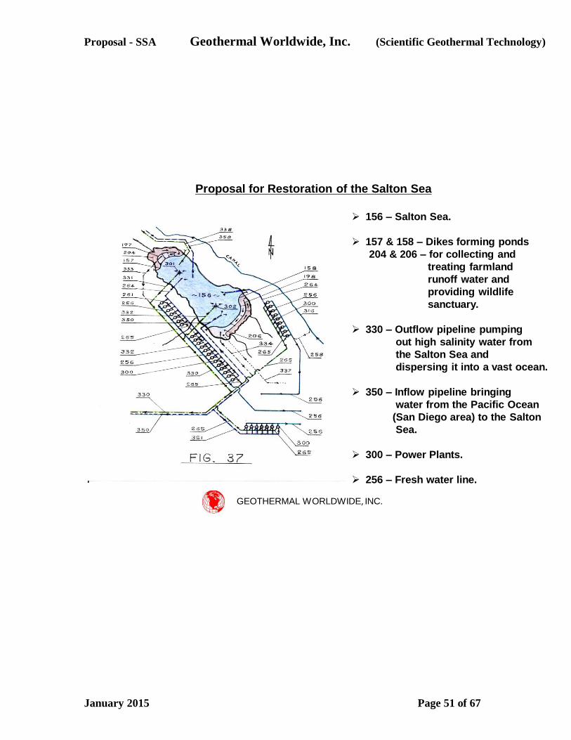
Proposal - SSA Geothermal Worldwide, Inc. (Scientific Geothermal Technology)
January 2015 Page 51 of 67
GEOTHERMAL WORLDWIDE, INC.
Proposal for Restoration of the Salton Sea
156 – Salton Sea.
157 & 158 – Dikes forming ponds
204 & 206 – for collecting and
treating farmland
runoff water and
providing wildlife
sanctuary.
330 – Outflow pipeline pumping
out high salinity water from
the Salton Sea and
dispersing it into a vast ocean.
350 – Inflow pipeline bringing
water from the Pacific Ocean
(San Diego area) to the Salton
Sea.
300 – Power Plants.
256 – Fresh water line.
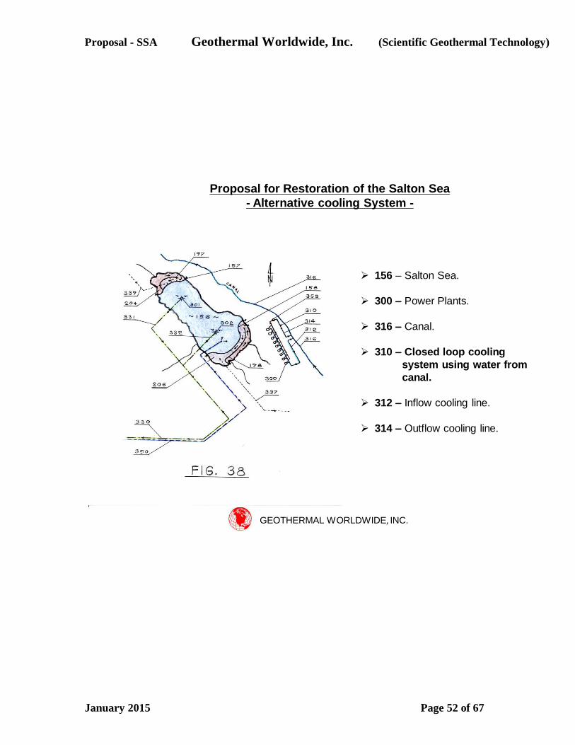
Proposal - SSA Geothermal Worldwide, Inc. (Scientific Geothermal Technology)
January 2015 Page 52 of 67
GEOTHERMAL WORLDWIDE, INC.
Proposal for Restoration of the Salton Sea
- Alternative cooling System -
156 – Salton Sea.
300 – Power Plants.
316 – Canal.
310 – Closed loop cooling
system using water from
canal.
312 – Inflow cooling line.
314 – Outflow cooling line.
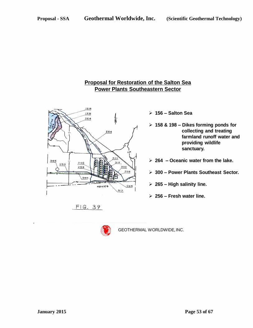
Proposal - SSA Geothermal Worldwide, Inc. (Scientific Geothermal Technology)
January 2015 Page 53 of 67
GEOTHERMAL WORLDWIDE, INC.
Proposal for Restoration of the Salton Sea
Power Plants Southeastern Sector
156 – Salton Sea
158 & 198 – Dikes forming ponds for
collecting and treating
farmland runoff water and
providing wildlife
sanctuary.
264 – Oceanic water from the lake.
300 – Power Plants Southeast Sector.
265 – High salinity line.
256 – Fresh water line.
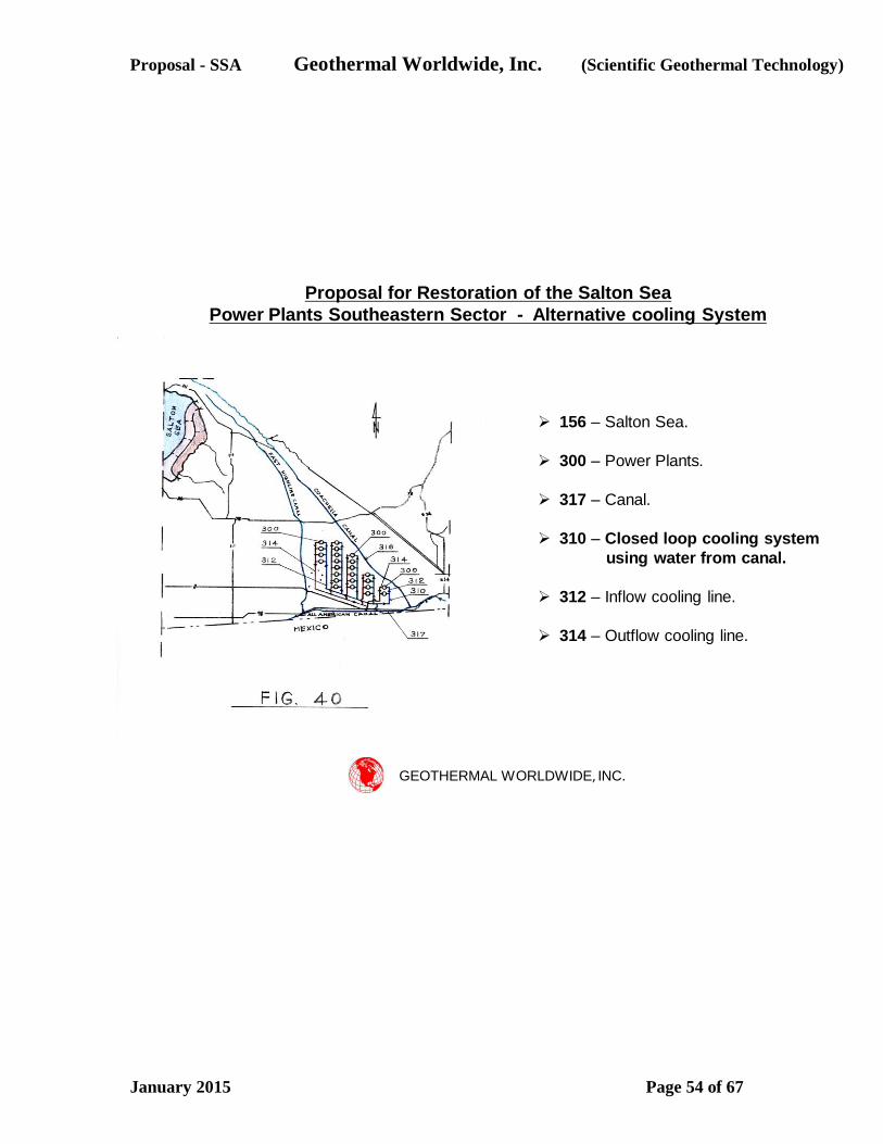
Proposal - SSA Geothermal Worldwide, Inc. (Scientific Geothermal Technology)
January 2015 Page 54 of 67
GEOTHERMAL WORLDWIDE, INC.
Proposal for Restoration of the Salton Sea
Power Plants Southeastern Sector - Alternative cooling System
156 – Salton Sea.
300 – Power Plants.
317 – Canal.
310 – Closed loop cooling system
using water from canal.
312 – Inflow cooling line.
314 – Outflow cooling line.
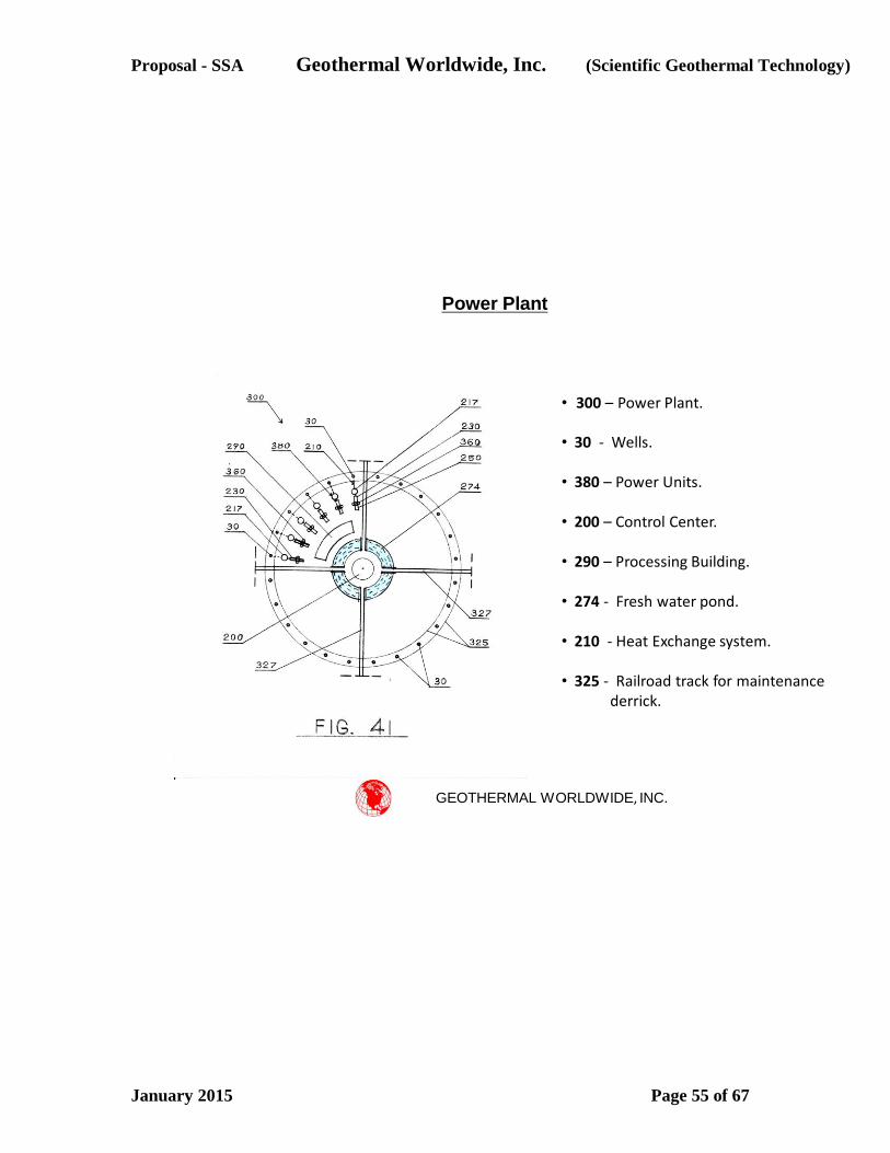
Proposal - SSA Geothermal Worldwide, Inc. (Scientific Geothermal Technology)
January 2015 Page 55 of 67
GEOTHERMAL WORLDWIDE, INC.
Power Plant
• 300 – Power Plant.
• 30 - Wells.
• 380 – Power Units.
• 200 – Control Center.
• 290 – Processing Building.
• 274 - Fresh water pond.
• 210 - Heat Exchange system.
• 325 - Railroad track for maintenance derrick.
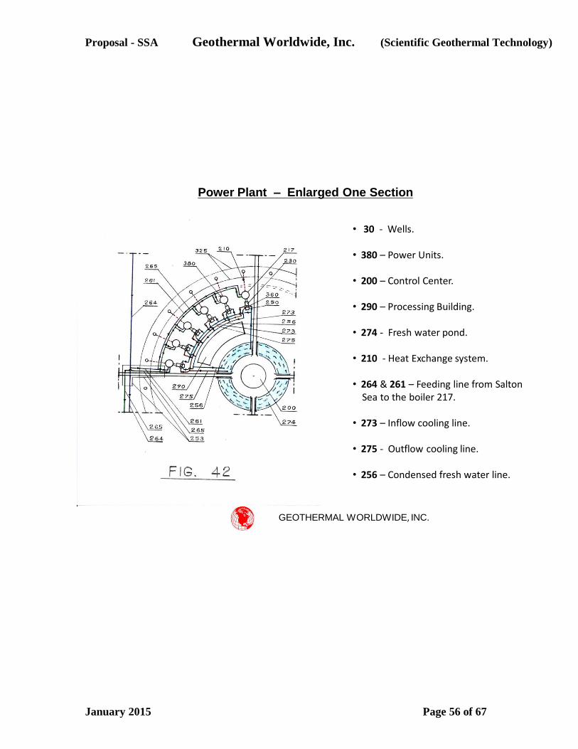
Proposal - SSA Geothermal Worldwide, Inc. (Scientific Geothermal Technology)
January 2015 Page 56 of 67
GEOTHERMAL WORLDWIDE, INC.
Power Plant – Enlarged One Section
• 30 - Wells.
• 380 – Power Units.
• 200 – Control Center.
• 290 – Processing Building.
• 274 - Fresh water pond.
• 210 - Heat Exchange system.
• 264 & 261 – Feeding line from Salton Sea to the boiler 217.
• 273 – Inflow cooling line.
• 275 - Outflow cooling line.
• 256 – Condensed fresh water line.

Proposal - SSA Geothermal Worldwide, Inc. (Scientific Geothermal Technology)
January 2015 Page 57 of 67
GEOTHERMAL WORLDWIDE, INC.
Power Plant – Enlarged One Section - Alternative
• 30 - Wells.
• 380 – Power Units.
• 200 – Control Center.
• 290 – Processing Building.
• 274 - Fresh water pond.
• 210 - Heat Exchange system.
• 264 & 261 – Feeding line from Salton Sea to the boiler 217.
• 360 - Condenser with air cooling.
• 256 – Condensed fresh water line.
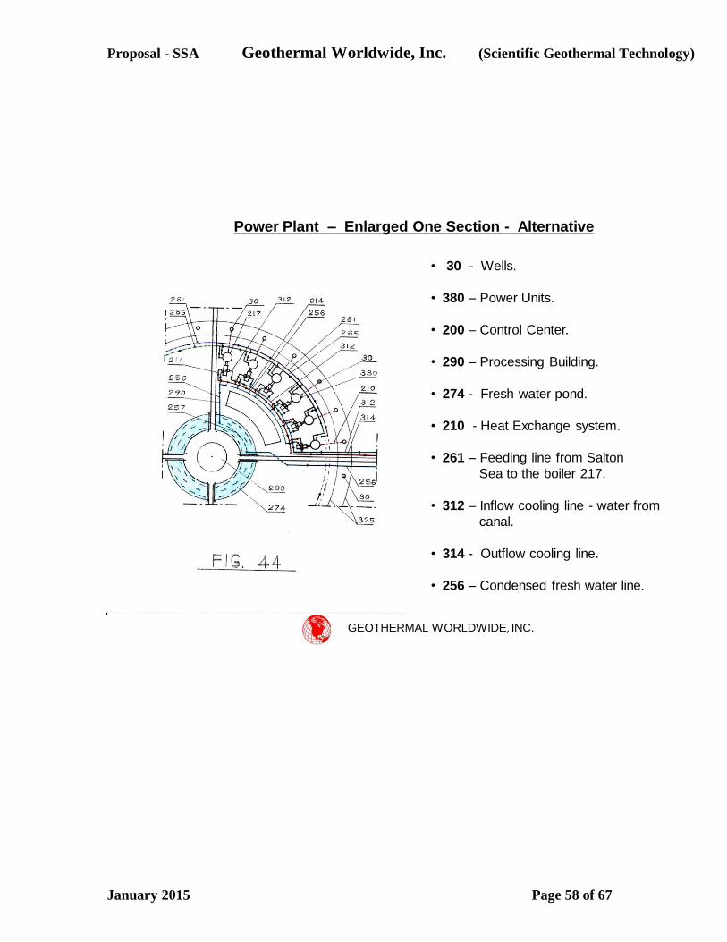
Proposal - SSA Geothermal Worldwide, Inc. (Scientific Geothermal Technology)
January 2015 Page 58 of 67
GEOTHERMAL WORLDWIDE, INC.
Power Plant – Enlarged One Section - Alternative
• 30 - Wells.
• 380 – Power Units.
• 200 – Control Center.
• 290 – Processing Building.
• 274 - Fresh water pond.
• 210 - Heat Exchange system.
• 261 – Feeding line from Salton
Sea to the boiler 217.
• 312 – Inflow cooling line - water from
canal.
• 314 - Outflow cooling line.
• 256 – Condensed fresh water line.
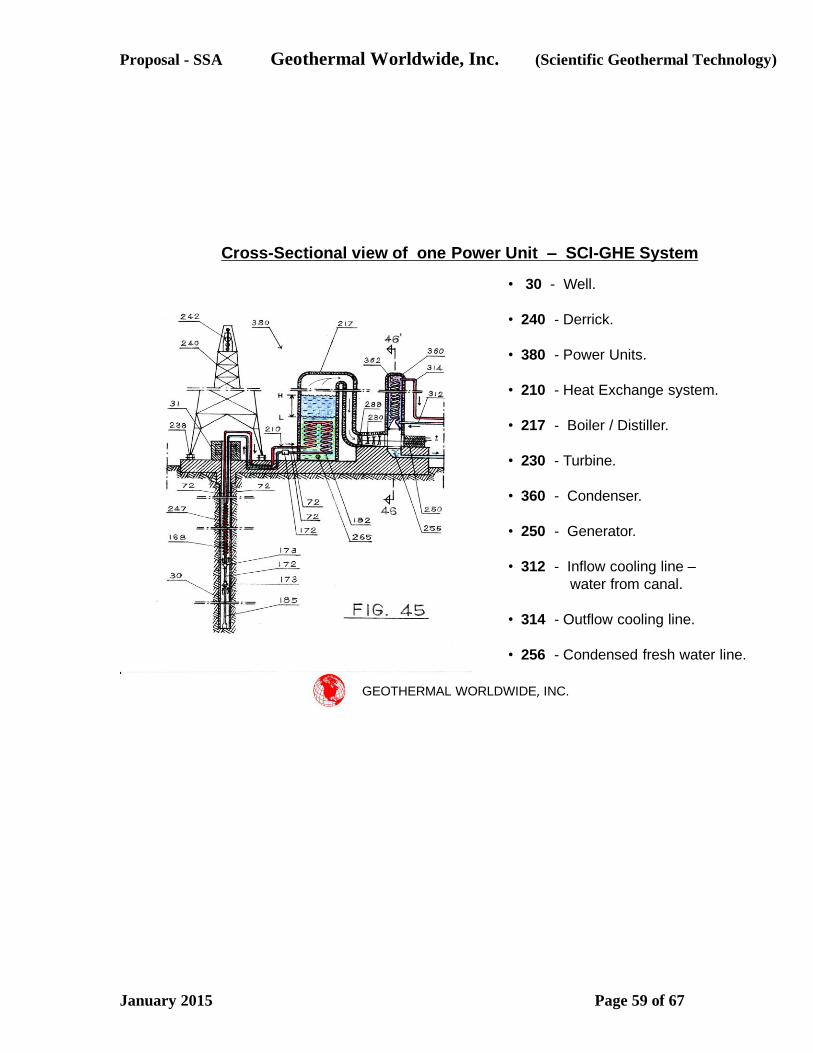
Proposal - SSA Geothermal Worldwide, Inc. (Scientific Geothermal Technology)
January 2015 Page 59 of 67
GEOTHERMAL WORLDWIDE, INC.
Cross-Sectional view of one Power Unit – SCI-GHE System
• 30 - Well.
• 240 - Derrick.
• 380 - Power Units.
• 210 - Heat Exchange system.
• 217 - Boiler / Distiller.
• 230 - Turbine.
• 360 - Condenser.
• 250 - Generator.
• 312 - Inflow cooling line –
water from canal.
• 314 - Outflow cooling line.
• 256 - Condensed fresh water line.
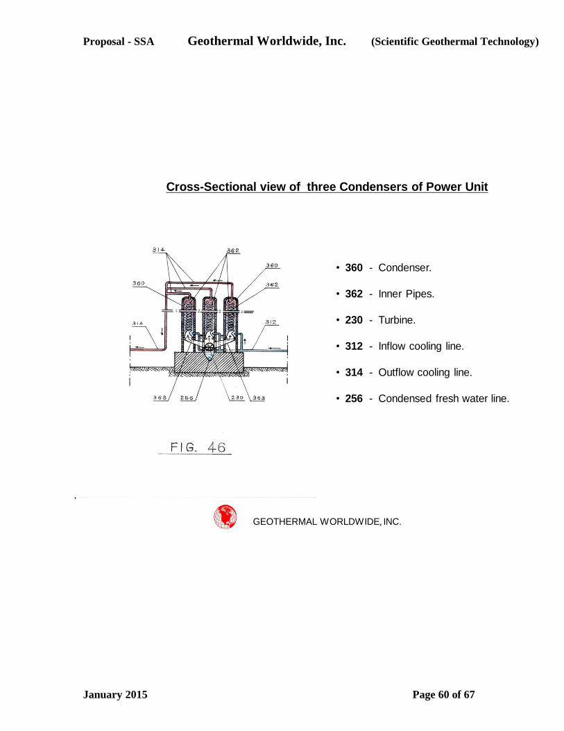
Proposal - SSA Geothermal Worldwide, Inc. (Scientific Geothermal Technology)
January 2015 Page 60 of 67
GEOTHERMAL WORLDWIDE, INC.
Cross-Sectional view of three Condensers of Power Unit
• 360 - Condenser.
• 362 - Inner Pipes.
• 230 - Turbine.
• 312 - Inflow cooling line.
• 314 - Outflow cooling line.
• 256 - Condensed fresh water line.

Proposal - SSA Geothermal Worldwide, Inc. (Scientific Geothermal Technology)
January 2015 Page 61 of 67
GEOTHERMAL WORLDWIDE, INC.
Schematic Plan view of Power Unit
with alternative two secondary binary Power Units
• 30 - Well.
• 380 - Power Units.
• 210 - Heat Exchange system.
• 217 - Boiler / Distiller.
• 230 - Turbine.
• 360 - Condenser.
• 250 - Generator.
• 312 - Inflow cooling line.
• 314 - Outflow cooling line.
• 256 - Condensed fresh water line.
• 381 & 382 - Binary Power Unit.
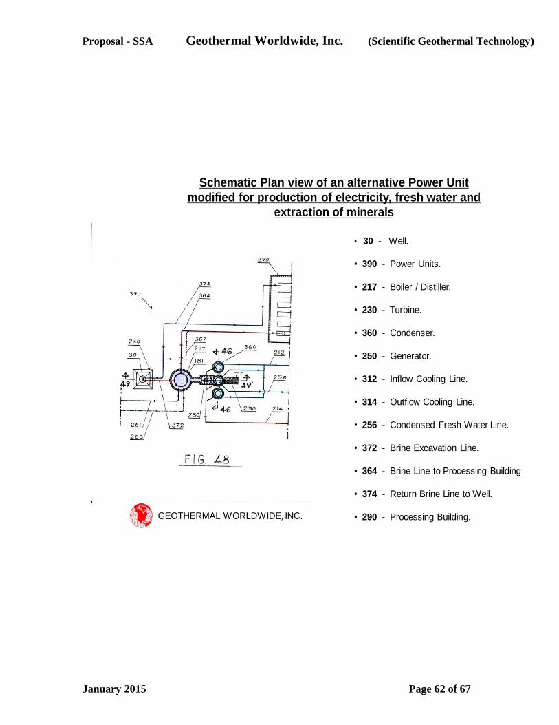
Proposal - SSA Geothermal Worldwide, Inc. (Scientific Geothermal Technology)
January 2015 Page 62 of 67
GEOTHERMAL WORLDWIDE, INC.
Schematic Plan view of an alternative Power Unit
modified for production of electricity, fresh water and
extraction of minerals
• 30 - Well.
• 390 - Power Units.
• 217 - Boiler / Distiller.
• 230 - Turbine.
• 360 - Condenser.
• 250 - Generator.
• 312 - Inflow Cooling Line.
• 314 - Outflow Cooling Line.
• 256 - Condensed Fresh Water Line.
• 372 - Brine Excavation Line.
• 364 - Brine Line to Processing Building
• 374 - Return Brine Line to Well.
• 290 - Processing Building.
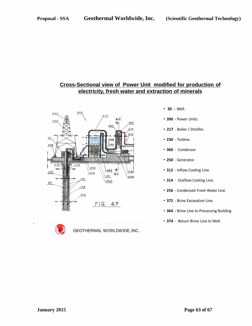
Proposal - SSA Geothermal Worldwide, Inc. (Scientific Geothermal Technology)
January 2015 Page 63 of 67
GEOTHERMAL WORLDWIDE, INC.
Cross-Sectional view of Power Unit modified for production of
electricity, fresh water and extraction of minerals
• 30 - Well.
• 390 - Power Units.
•. 217 - Boiler / Distiller.
• 230 - Turbine.
• 360 - Condenser.
• 250 - Generator.
• 312 - Inflow Cooling Line.
• 314 - Outflow Cooling Line.
• 256 - Condensed Fresh Water Line.
• 372 - Brine Excavation Line.
• 364 - Brine Line to Processing Building
• 374 - Return Brine Line to Well.
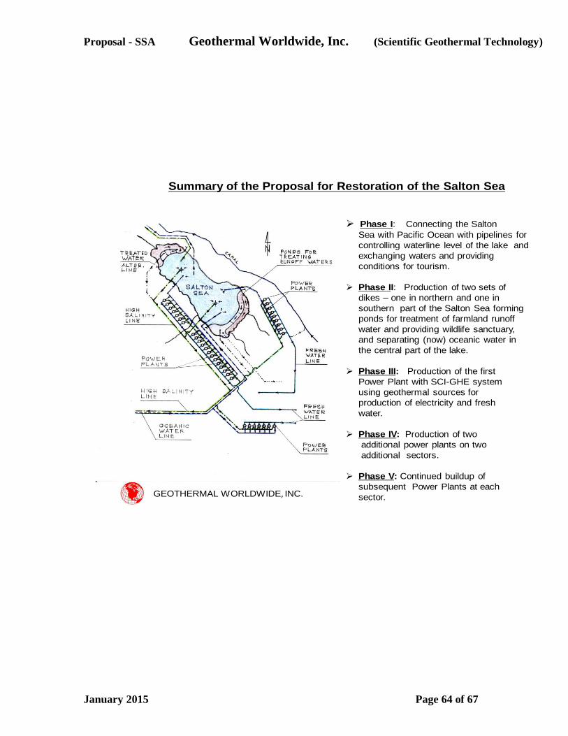
Proposal - SSA Geothermal Worldwide, Inc. (Scientific Geothermal Technology)
January 2015 Page 64 of 67
Summary of the Proposal for Restoration of the Salton Sea
GEOTHERMAL WORLDWIDE, INC.
Phase I: Connecting the Salton
Sea with Pacific Ocean with pipelines for
controlling waterline level of the lake and
exchanging waters and providing
conditions for tourism.
Phase II: Production of two sets of
dikes – one in northern and one in
southern part of the Salton Sea forming
ponds for treatment of farmland runoff
water and providing wildlife sanctuary,
and separating (now) oceanic water in
the central part of the lake.
Phase III: Production of the first
Power Plant with SCI-GHE system
using geothermal sources for
production of electricity and fresh
water.
Phase IV: Production of two
additional power plants on two
additional sectors.
Phase V: Continued buildup of
subsequent Power Plants at each
sector.

Proposal - SSA Geothermal Worldwide, Inc. (Scientific Geothermal Technology)
January 2015 Page 65 of 67
BACKGROUND AND ADDITIONAL INFORMATION
I am the founder of the Geothermal Worldwide, Inc., and the author of an unrivaled methodology
for harnessing geothermal energy for generation of electricity without polluting the environment.
I am also the author of an innovative methodology for drilling faster, deeper and wider well-bores
“Apparatus for Drilling Faster, Deeper and Wider Well-bore”.
My methodology, the "Self Contained In-Ground Geothermal Generator" (SCI-GGG); “Self
Contained In-Ground Heat Exchanger" (SCI-GHE) systems; and “In-Line Pump”; commonly
called "Scientific Geothermal Technology", is a new approach for harnessing geothermal energy
– a much better way than conventional geothermal systems and/or experimental Enhanced
Geothermal Systems (EGS), both of which have serious shortcomings.
In summary – We all know that there is an enormous source of energy under our feet whether it is
a few miles underground or on the surface in locations such as Hawaii. The question was, until
now, how to harness it expediently and efficiently?
The "Scientific Geothermal Technology" consists of several designs and variations
complementing each other. They can operate separately in many different applications in the
energy sectors.
The SCI-GGG system uses several completely closed loop systems and generates electricity
down at the heat source and transmits it up to the ground level by means of electrical cables. The
SCI-GGG apparatus consist of a boiler, a turbine, a generator and a condenser. The boiler is
exposed to the source of heat. The engine compartment is thermally insulated and cooled with a
second closed loop system which is engaged with a third closed loop system at ground level and
generates additional electricity.
By lowering the SCI-GGG apparatus in a pre-drilled well bore to the hot substrate of the Earth’s
crust, electricity is generated below the ground and transmitted up to the surface by cable and
subsequently through existing electrical grids to residences and industry.
The SCI-GHE system is an integral part of the SCI-GGG system and can be used separately as
an independent heat exchange apparatus. The SCI-GHE apparatus consist of: two coils (heat
exchangers); a closed loop thermally insulated line; at least one in-line pump; and a “binary
power unit”.
By lowering a first coiled pipe (heat exchanger) in a pre-drilled well bore to the source of heat
(hot rocks or hydrothermal reservoir) heat is absorbed and transported with circulating fluid
through a thermally insulated closed loop line to the second coiled pipe (heat exchanger) which is
connected with a second closed loop system (binary power unit) at ground level which generates
electricity by using Organic Rankine Cycle (ORC) which is then transmitted through the
electricity grid to residences and industry.
The IN-LINE PUMP is an integral part of the SCI-GGG & SCI-GHE systems designed for
circulating fluids through a closed loop systems and can also be used effectively in many
Proposal - SSA Geothermal Worldwide, Inc. (Scientific Geothermal Technology)
January 2015 Page 66 of 67
applications wherever substantial pumping force is needed. For example, my IN-LINE- PUMP
can be used for pumping up oil from oil wells (reservoirs) in which geo-pressure is low, or any
other type of fluid from a reservoir, such as, but not limited to, water or natural gas. The IN-LINE
PUMP is an electromotor with cylindrical shape and can be inserted as a repetitive segment. It
has no length limitation thereby increasing power to the electromotor and imparts added pumping
to circulate fluid at desired speed.
I am confident that my methodology can harness geothermal energy more expediently and in the
future completely replaced nuclear, oil and coal as energy sources for the production of
electricity.
Presently, I am endeavoring to bring the benefits of my patented technology to the attention of
parties that might be interested in licensing my technology.
I am in the process of reaching professionals in the energy industry, academics, and more
specifically geothermal professionals, especially those who are in the process of planning or
developing new geothermal projects.
I would like to emphasize that the cost for implementing my methodology, (especially SCI-GHE
system), instead of conventional technology in the construction of new power plants would be
less expensive. Power plants implementing the “Scientific Geothermal Technology” will be
dealing with less constraint and less maintenance expenses resulting in higher return on
investment.
It is self-evident that the SCI-GGG and/or SCI-GHE system will outperform any conventional
geothermal power plant at the same location. How? – Because "Scientific Geothermal
Technology” uses several completely closed loop systems and only absorbs heat from the heat
source. It neither injects fluids into the ground nor pumps up geothermal fluids on the ground
surface. Ground fluids do not pass through the equipment.
Although the main purpose of my systems is to replace nuclear, coal and oil burning power
plants, I would also like to mention that my systems, suitably scaled and installed down hole can
generate additional revenue by harnessing heat from marginal and abandoned oil well bores.
Since I am searching at this time for producers / licensees’ and investors / shareholders I am
mentioning both aspects.
The following addresses the Geothermal Worldwide, Inc.’s Business Model.
With my background in engineering, I was able to develop this unrivaled methodology. The main
attribute of my concept is simplicity of it and the necessity for it.
I have three patents already issued with broad claims and I have several patent pending
applications focusing on details.
The mission of the Geothermal Worldwide, Inc. is licensing the methodology to large capable
producers worldwide.
There are 4 licensing proposals;
Licensing for Limited right by a Single Project;
Proposal - SSA Geothermal Worldwide, Inc. (Scientific Geothermal Technology)
January 2015 Page 67 of 67
Licensing for Limited right by a Single Country;
Licensing for Limited right by Region;
Licensing for Exclusive right;
Licensing Agreement entitlement requires a licensee to pay a certain percentage of revenue
gained from electricity sold. There is also a Partnership Option - (Investors / Shareholders). There
is an incentive for early investors.
The advancement of the "Scientific Geothermal Technology" would save a lot of effort, money
and most importantly, it would contribute to global economies and a greener environment.
I respectfully urge the members of the Salton Sea Authority to thoroughly review my proposal for
restoration of the Salton Sea. Assuming that the Salton Sea Authority will recognize the
importance of this proposal for our community, economy and environment, it is imperative that
the Salton Sea Authority inform everyone that is involved in the Salton Sea issues - including
public. I respectfully urge the members of the Salton Sea Authority to organize further actions
and inform everyone that has potential and power to voice and do its best on local, state and
federal level in providing funding for implementation of this proposal. Restoration of the Salton
Sea and implementation of the Scientific Geothermal Technology is in interest to all of us - not
just locally but worldwide. I am eager further to help.
Sincerely,
Nikola N. Lakic
Graduate Eng. Architect
Geothermal Worldwide, Inc.
78-365 Hwy 111, #402
La Quinta, CA 92253
USA
01-760-347-1609
01-760-333-3851 cell
www.GeothermalWorldwide.com
NOTE: Proposal updated September 7, 2015, with recently obtained information about rough cost
estimate, which was lacking in the previous proposal, and additional references regarding
presentation at the Southern Methodist University (SMU) and a few clarifying sentences.