proposed adelaide desalination plant - … proposed adelaide desalination plant environmental impact...
TRANSCRIPT
PROPOSED ADELAIDEDESALINATION PLANT
Chapter 3 – Descriptionof Project


Proposed Adelaide Desalination Plant Environmental Impact Statement Chapter 3 – Description of Project i
Contents
3.1 Introduction 13.1.1 Project Description 13.1.2 The Desalination Process 13.1.3 Environmental Drivers and Performance Criteria 33.1.4 Compliance with Environmental Performance Criteria 13
3.2 Description of Existing Environment 153.2.1 Description of the Port Stanvac Site 153.2.1.1 Selection of the Northern Land at Port Stanvac 153.2.1.2 Northern Site Description 163.2.1.3 Description of Surrounding Locality 17
3.3 Nature of Proposal 183.3.1 Description of Desalination Plant 183.3.1.1 System Capacity 193.3.1.2 Plant Footprint 203.3.1.3 Intake Pumping Station and Screening 203.3.1.4 Pre-Treatment System 223.3.1.5 Reverse Osmosis System 233.3.1.6 Post-Treatment System 243.3.1.7 Treated Water Storage 243.3.1.8 Plant Control System 243.3.1.9 Buildings and Civil Structures 253.3.1.10 Chemical Storage 253.3.2 Description of Marine Structures 263.3.2.1 General 263.3.2.2 Seawater Intake Structure 263.3.2.3 Outfall Structure (Diffuser) 273.3.2.4 Intake and Outfall Conduits 283.3.3 Waste Management 303.3.4 Water Quality Monitoring Systems 303.3.5 Electricity Supply and Energy Requirements 313.3.5.1 Specific Energy Consumption 313.3.5.2 Backup Power 323.3.5.3 Energy Recovery 32
3.4 Management Arrangements 333.4.1 Design Management 333.4.2 Site Management and Construction 333.4.3 Operation and Maintenance 333.4.4 Plant Reliability 33
3.5 Decommissioning 353.5.1 Permanent Decommissioning 353.5.2 Decommissioning Plan 35

Proposed Adelaide Desalination Plant Environmental Impact Statement Chapter 3 – Description of Project 1
3.1 IntroductionThis Chapter describes the proposed Desalination Plant. It discusses the desalinationprocess, the proposed site of the development at Port Stanvac and the three keycomponents of the proposal, including the Desalination Plant, intake and outfall systemsand the power supply infrastructure.
The design and environmental performance criteria for the key components are outlinedalong with SA Water’s proposed management arrangements and project executiontimeframes.
The EIS has been prepared on the basis of the Concept Design developed for theDesalination Plant that includes consideration of design options, project feasibility andassociated environmental assessments. The Concept Design is expressed as drawingsthat set out indicative arrangements and locations for the Desalination Plant structures,marine works (comprising intake and outfall structures and conduits), buildings, civil andelectrical works.
The successful Contractor will be required to design and deliver the proposedDesalination Plant in accordance with specified environmental and engineeringperformance objectives and functional requirements established by SA Water for theproposed development (Table 3.1). The final design may vary from the Concept Designbut must meet the detailed environmental and engineering performance criteria.
It should be noted that both the transfer pipeline system for pumping treated water fromthe proposed Desalination Plant to the HVWTP and the ETSA infrastructure are subjectto separate development approval processes.
3.1.1 Project DescriptionThe proposed ADP project is a reverse osmosis Desalination Plant with an initialproduction capacity of 50 GL per annum and infrastructure designed for futureexpansion to supply up to 100 GL per annum of drinking water. The intake and outfallsystems will draw or take seawater into the facility and return saline concentrate to GulfSt Vincent.
The proposed Desalination Plant is designed to be a flexible load plant, capable ofoperating at full capacity (i.e. 100 GL per annum), or at lower levels of production.Given the array of factors likely to affect the level of production required, theDesalination Plant needs to have sufficient flexibility to be efficiently operated at fullcapacity or at lower production levels.
The flexible load Desalination Plant complements the South Australian Government’sFour Way Water Security Strategy, in that the supply of water sourced from desalinationis not intended to replace other measures, but has been designed to diversify, enhanceand secure a reliable water supply for metropolitan Adelaide.
A description of the proposed Desalination Plant, its constituent parts and associatedworks is provided below.
3.1.2 The Desalination ProcessThe process of desalination removes dissolved salts and impurities from a water sourcesuch as seawater to convert it to drinking water. The benefit of the desalination process

2 Proposed Adelaide Desalination Plant Environmental Impact Statement Chapter 3 – Description of Project
is that the raw water source does not depend on rainfall, making it climate independentand capable of providing water throughout the year.
Reverse osmosis desalination works by using high pressure semi-permeablemembranes. Fresh water, with a very small quantity of salt, passes through themembrane leaving a concentrated salt stream that is then discharged back to theocean. Typically for every 100 litres of raw seawater, approximately 40 to 45 litres ofdrinking water is produced.
Reverse osmosis technology has been adopted for all of the large seawaterdesalination plants recently constructed or planned in Australia, including plants inPerth, the Gold Coast, Sydney and Melbourne.
An overview of the desalination process based on reverse osmosis is shown inFigure 3.1 below.
Figure 3.1 Desalination Process
The desalination process can be summarised as follows:
Seawater is drawn into the intake structure, which is designed to minimise theentrainment and entrapment of marine biota, sand and debris. The intake water isscreened to remove large matter and then pumped to the pre-treatment process.
The pre-treatment process (described below) removes suspended solids, oil andgrease and other particle matter that could block, damage or foul the reverseosmosis membranes.
The seawater is then pumped at high pressure through the reverse osmosismembranes to separate water from the seawater. The membranes retain the saltsand other impurities, while the clean water (containing little salt) passes through themembranes and is termed permeate. Periodically, the membranes must bechemically cleaned to remove accumulated materials. Spent chemical solutions areneutralised prior to disposal via a trade waste point or, if appropriate, released at acontrolled rate to the outfall, subject to compliance with EPA requirements.

Proposed Adelaide Desalination Plant Environmental Impact Statement Chapter 3 – Description of Project 3
The saline concentrate produced as part of the reverse osmosis process is passedthrough an energy recovery system prior to discharge to the marine environment viathe outfall. The diffuser structure located at the end of the outfall pipe will bedesigned to ensure that the discharge will be well mixed with the receiving water.
The permeate water is re-mineralised via a post-treatment process. This processensures that the desalinated water satisfies the health and aesthetic requirements ofthe Drinking Water Specification and the Australian Drinking Water Guidelines.Fluoridation and chlorine disinfection form part of the post-treatment process.Compliance with these standards has been included as part of SA Water’scontractual obligations imposed on the Contractor.
The treated water is stored temporarily in a balancing storage tank prior to pumpingto the Happy Valley System via the transfer pump station and pipeline for blendingwith conventionally treated surface water and reticulation via the Adelaide watersupply network.
3.1.3 Environmental Drivers and Performance CriteriaThe proposed Desalination Plant is to be developed to meet specified performancecriteria for design, construction and operation to ensure that environmental protectionobjectives are achieved. These objectives have been fundamental in driving theConcept Design of the proposed Desalination Plant.
The following Table 3.1 outlines the key environmental objectives and performancecriteria for the Desalination Plant. The objectives and criteria have been developed fromthe environmental impact assessment process undertaken as part of the EIS.
The environmental objectives and performance criteria will be applied throughout theproject life cycle and will be subject to ongoing refinement by SA Water based oncommunity feedback. They will also be implemented and monitored in order to meetthe overall project objectives presented in Chapter 2.
4 Proposed Adelaide Desalination Plant Environmental Impact Statement Chapter 3 – Description of Project
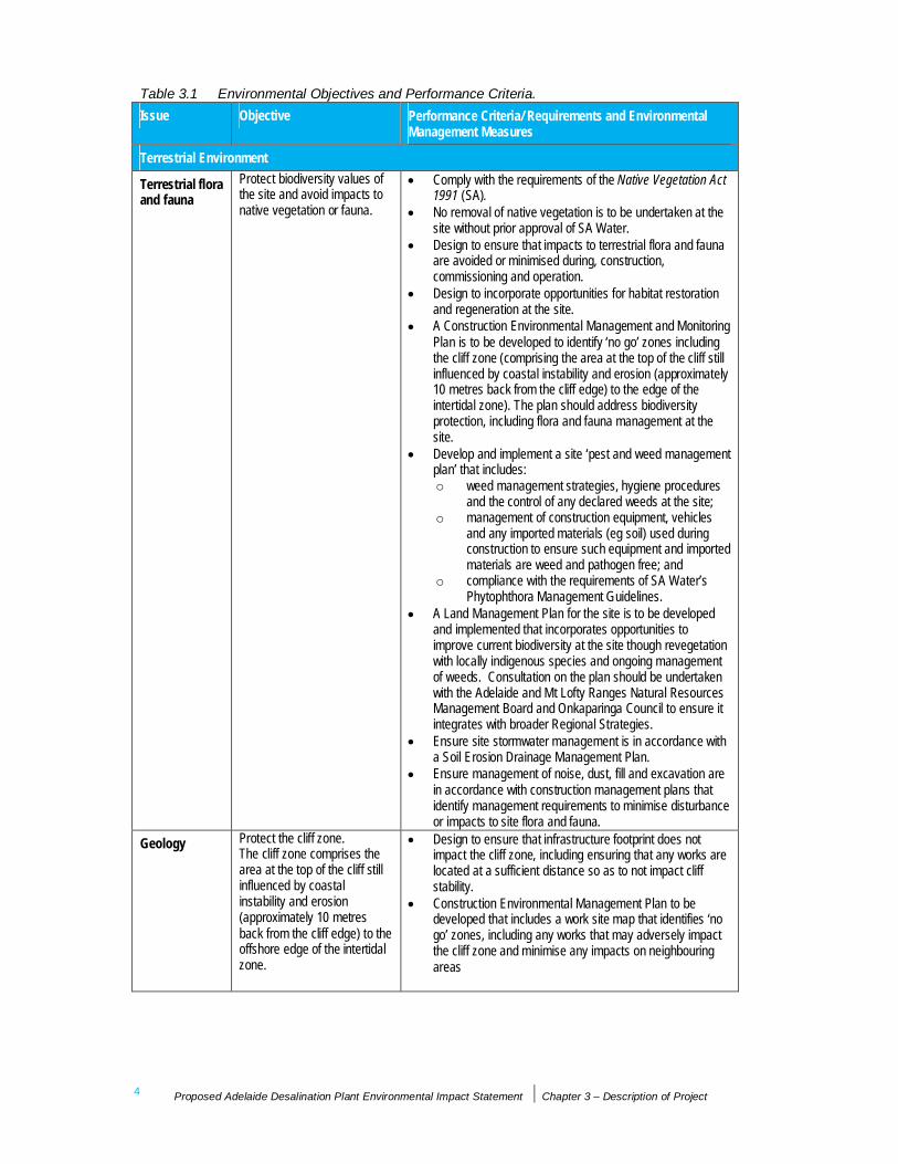
Table 3.1 Environmental Objectives and Performance Criteria.Issue Objective Performance Criteria/ Requirements and Environmental
Management Measures
Terrestrial Environment
Terrestrial floraand fauna
Protect biodiversity values ofthe site and avoid impacts tonative vegetation or fauna.
Comply with the requirements of the Native Vegetation Act1991 (SA).No removal of native vegetation is to be undertaken at thesite without prior approval of SA Water.Design to ensure that impacts to terrestrial flora and faunaare avoided or minimised during, construction,commissioning and operation.Design to incorporate opportunities for habitat restorationand regeneration at the site.A Construction Environmental Management and MonitoringPlan is to be developed to identify ‘no go’ zones includingthe cliff zone (comprising the area at the top of the cliff stillinfluenced by coastal instability and erosion (approximately10 metres back from the cliff edge) to the edge of theintertidal zone). The plan should address biodiversityprotection, including flora and fauna management at thesite.Develop and implement a site ‘pest and weed managementplan’ that includes:o weed management strategies, hygiene procedures
and the control of any declared weeds at the site;o management of construction equipment, vehicles
and any imported materials (eg soil) used duringconstruction to ensure such equipment and importedmaterials are weed and pathogen free; and
o compliance with the requirements of SA Water’sPhytophthora Management Guidelines.
A Land Management Plan for the site is to be developedand implemented that incorporates opportunities toimprove current biodiversity at the site though revegetationwith locally indigenous species and ongoing managementof weeds. Consultation on the plan should be undertakenwith the Adelaide and Mt Lofty Ranges Natural ResourcesManagement Board and Onkaparinga Council to ensure itintegrates with broader Regional Strategies.Ensure site stormwater management is in accordance witha Soil Erosion Drainage Management Plan.Ensure management of noise, dust, fill and excavation arein accordance with construction management plans thatidentify management requirements to minimise disturbanceor impacts to site flora and fauna.
Geology Protect the cliff zone.The cliff zone comprises thearea at the top of the cliff stillinfluenced by coastalinstability and erosion(approximately 10 metresback from the cliff edge) to theoffshore edge of the intertidalzone.
Design to ensure that infrastructure footprint does notimpact the cliff zone, including ensuring that any works arelocated at a sufficient distance so as to not impact cliffstability.Construction Environmental Management Plan to bedeveloped that includes a work site map that identifies ‘nogo’ zones, including any works that may adversely impactthe cliff zone and minimise any impacts on neighbouringareas

Proposed Adelaide Desalination Plant Environmental Impact Statement Chapter 3 – Description of Project 5
Issue Objective Performance Criteria/ Requirements and EnvironmentalManagement Measures
Greenhousegases
Minimise energy use andgreenhouse gas emissionsthroughout design,construction and operation.
Development and implementation of SustainabilityManagement Plans for each phase of the project tominimise the greenhouse footprint through design,construction and operation.Incorporation of energy efficiency into the layout anddesign of the Desalination Plant.Selection and sourcing of materials for the DesalinationPlant must take into account whole-life impacts andembodied energy.Incorporation of opportunities to include solar or other smallscale on-site energy generation opportunities as part of thefinal design.Specific energy consumption to be equal to or better thannational / international benchmark standards and achieveless than 4.5 kWh per KL of drinking water produced forthe plant, excluding the Transfer Pumping Station.Incorporation of energy recovery systems in the processplant and outfall system.Incorporate energy efficient equipment within theDesalination Plant to minimise energy consumption.The environmental impact of energy use to be minimisedduring construction and operation by minimising theconsumption of all forms of energy (fuels, electricity),minimising production of emissions.
AboriginalHeritage
Protect sites of AboriginalHeritage significance andavoid impacts. Manageinteractions with known andunknown heritage sites.
Ensure compliance with the requirements of the AboriginalHeritage Act 1988 (SA).Ensure ongoing consultation with the local AboriginalCommunity on the project through the Kaurna HeritageBoard.Design the plant footprint to avoid any areas of identifiedAboriginal heritage significance.Develop and implement a Cultural Heritage ManagementPlan for the works that includes induction requirements andcultural awareness training for contractors and protocols forthe management of items of heritage significance, if found.Ensure the Construction Environmental Management andMonitoring Plan (CEMMP) site map that identifies knownareas or sites to avoid.Actively identify and incorporate opportunities in the projectto acknowledge and recognise Kaurna connection with theland and waters, including recognition of the Tjilbruke trailthrough signage and other mechanisms to be developed inconsultation with the KHB.Establish a keeping place for any artefacts salvaged duringthe construction process.
Non-AboriginalHeritage
Protect historic places andsites from disturbance whereimpacts can be avoided.Manage interactions withknown and unknown heritage.
Development and implement a Cultural HeritageManagement Plan for the construction and operation of theDesalination Plant..
6 Proposed Adelaide Desalination Plant Environmental Impact Statement Chapter 3 – Description of Project
Issue Objective Performance Criteria/ Requirements and EnvironmentalManagement Measures
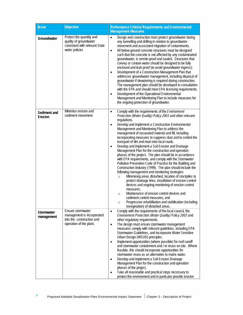
Groundwater Protect the quantity andquality of groundwaterconsistent with relevant Statewater policies
Design and construction must protect groundwater duringany tunnelling and drilling in relation to groundwatermovement and associated migration of contaminants.All below ground concrete structures must be designedsuch that the concrete is not affected by any contaminatedgroundwater, is vermin proof and sealed. Structures thatconvey or contain water should be designed to be fullyenclosed and leak proof (to avoid groundwater ingress).Development of a Construction Management Plan thataddresses groundwater management, including disposal ofgroundwater if dewatering is required during construction.The management plan should be developed in consultationwith the EPA and should meet EPA licensing requirements.Development of the Operational EnvironmentalManagement and Monitoring Plan to include measures forthe ongoing protection of groundwater.
Sediment andErosion
Minimise erosion andsediment movement.
Comply with the requirements of the EnvironmentProtection (Water Quality) Policy 2003 and other relevantregulations.Develop and implement a Construction EnvironmentalManagement and Monitoring Plan to address themanagement of excavated material and fill, includingincorporating measures to suppress dust and to control thetransport of dirt and mud onto local roads.Develop and implement a Soil Erosion and DrainageManagement Plan for the construction and operationphases of the project. The plan should be in accordancewith EPA requirements, and comply with the StormwaterPollution Prevention Code of Practice for the Building andConstruction Industry (1999). The plan should include thefollowing management and monitoring strategies:o Minimising areas disturbed, location of stockpiles to
protect drainage lines, installation of erosion controldevices and ongoing monitoring of erosion controlmeasures;
o Maintenance of erosion control devices andsediment control measures; and
o Progressive rehabilitation and stabilisation (includingrevegetation) of disturbed areas.
Stormwatermanagement
Ensure stormwatermanagement is incorporatedinto the construction andoperation of the plant.
Comply with the requirements of the local council, theEnvironment Protection (Water Quality) Policy 2003 andother regulatory requirements.The design must ensure stormwater managementmeasures comply with relevant guidelines, including EPAStormwater Guidelines, and incorporate Water SensitiveUrban Design (WSUD) principles.Implement opportunities (where possible) for roof runoffand stormwater containment and / or reuse on site. Wherefeasible, this should incorporate opportunities forstormwater reuse as an alternative to mains water.Develop and implement a Soil Erosion DrainageManagement Plan for the construction and operationphases of the project.Take all reasonable and practical steps necessary toprotect the environment and in particular provide erosion

Proposed Adelaide Desalination Plant Environmental Impact Statement Chapter 3 – Description of Project 7
Issue Objective Performance Criteria/ Requirements and EnvironmentalManagement Measures
and sediment control measures required by the EPA. Thisshould include compliance with the Stormwater PollutionPrevention Code of Practice for the Building andConstruction Industry (1999).Chemical storage and delivery areas must be bunded inaccordance with the South Australia EPA Bunding and SpillManagement guidelines, and must ensure that any spillsdo not enter the site stormwater system.
Waterways Protect waterways andsurface water quality.
Develop and implement a Construction EnvironmentalManagement and Monitoring Plan that ensures no adverseimpact to waterways, including the development of a SoilErosion Drainage Management Plan for the constructionand operation phases of the project to protect the sitedrainage line from erosion, sedimentation and pollution.Adopt Water Sensitive Urban Design (WSUD) principles forthe design, construction and operation of the DesalinationPlant as part of surface water management at the site.During detailed design, undertake modelling of stormwatermanagement at the site to ensure compliance with therequirements of the Environment Protection (Water Quality)Policy 2003 and other regulatory requirements.
HazardousMaterials
Protect the environment andhuman health from theimpacts of hazardousmaterials.
Hazardous materials (including chemicals and fuels) mustbe stored within bunded areas in accordance with theSouth Australia EPA Bunding and Spill Managementguidelines, and must ensure that any spills do not enter thesite stormwater system.Limit the on-site storage of hazardous substances.Emergency response and contingency plans must bedeveloped that include procedures that deal with themanagement and reporting of any spills. Spill responsekits to be available on site (including for offshore works)and maintained to relevant standards.
Waste Minimise waste productionand manage wastesconsistent with relevant Statewaste policies and guidelines.
The Contractor must ensure that waste produced as aresult of construction activities is minimised.In assessing waste management options, adopt the wastemanagement hierarchy in order of preference:o Waste avoidance and reduction;o Maximise waste reuse, recovery and recycling;o Waste treatment; ando Waste disposal.Waste to be disposed of in accordance with EPAguidelines.Where possible, design excavation works should balancecut to fill to minimise the requirement for offsite disposal.
ResourceEfficiency
Maximise efficient use ofresources including minimisingresource use and maximisingrecovery and recycling.
Develop a Sustainability Management Plan for each projectphase.Incorporate reuse or recycling of materials where possible.Minimise water use and as part of the design, constructionand operation for temporary and permanent works.Incorporate reuse or recycling of water including rainwaterharvesting and stormwater recycling and reuse of constructionwater where possible.

8 Proposed Adelaide Desalination Plant Environmental Impact Statement Chapter 3 – Description of Project
Issue Objective Performance Criteria/ Requirements and EnvironmentalManagement Measures
Noise andVibration
Protect local amenity andminimise noise duringconstruction and operation,including from marine noiseand vibration.
Comply with the South Australian Environment Protection(Noise) Policy 2007.Incorporate noise abatement into the design of the plant.Ensure Noise and Vibration Management Plans aredeveloped for both construction and operation. Theseplans should be developed in consultation with the EPA.The plans must accurately predict noise or vibrations levelsgenerated from noisy activities and identify mitigationmeasures to minimise noise impacts, particularly toresidential areas. Such measures should include, wherefeasible:o Controlling noise at the source, incorporating less
noisy construction techniques;o Scheduling noisy activities for daytime hours in
accordance with any authorisations required underEnvironmental Protection Act 1993 (SA);
o Equipment maintenance and use of mufflers andsilencers; and
o Use of noise barriers.The Noise and Vibration Management Plan should includemonitoring (either on a regular or where requiredcontinuous basis) to verify that the noise levels generatedare not exceeding the criteria set by the EPA.
Air quality Protect air quality duringconstruction and operation.
Atmospheric emissions to comply with regulatoryrequirements, including the National EnvironmentalPollution Measure for Air Quality (NEPM), the EnvironmentProtection (Air Quality) Policy 1994 (SA) and theEnvironment Protection Act 1993 (SA).Develop and implement a Construction Air QualityManagement Plan, including specific measures to managedust and limit dust emissions.Minimise areas disturbed and potential dust emissions andensure disturbed areas are protected and revegetated assoon as possible.All construction vehicles must be maintained and havecovers (as required) to prevent any loss of load, whether inthe form of dust, liquid, solids or otherwise.The Contractor must ensure that all plant and equipment atthe site, or used in connection with the Contractor’sactivities, are maintained and operated in a proper andefficient manner.Ensure minimal odour to sensitive receptors with regulardisposal of waste and with waste disposal practices fullycompliant with regulatory requirements.Undertake regular inspections and reviews to confirmcompliance with regulatory requirements. Maintain acompliance register.
Visual amenity Protect visual amenity,including landscape andamenity values of thecoastline.
Design of Desalination Plant infrastructure and buildings toconsider visual amenity and the outcomes of the visualimpact assessment. This should include:o Buildings and plant layout to screen unsightly
features from view, including use of site levels;o Use of muted colours (eg ochres and greys) for
external finishes and the use of light reflecting

Proposed Adelaide Desalination Plant Environmental Impact Statement Chapter 3 – Description of Project 9
Issue Objective Performance Criteria/ Requirements and EnvironmentalManagement Measures
polished finishes, were appropriate; ando Any mounding or other landforms should be
integrated into the broader landscape to appear asnatural as possible.
Ensure landscaping and screening of the DesalinationPlant is undertaken, incorporating locally indigenousspecies.Minimise impacts associated with light spill during bothconstruction and operation, including:o the use of screens, where potential impacts are
identified; ando the use of lighting systems that illuminate the
minimum areas required for the minimum period oftime.
Traffic andTransport
Manage effects of increasedtraffic and transportationduring construction andoperation to minimise impactsto the community and protectpublic safety.
Develop and implement a Traffic Management Plan inconsultation with relevant Authorities to manage andminimise any adverse traffic impacts to the localcommunity and businesses during construction andoperation.Access to the site to consider impacts on the local andregional road network and to incorporate measure toreduce these impacts.Ensure ongoing communication with the local communityand businesses to manage any impacts associated withtraffic.
Social Manage and maintain ongoingcommunication with the localcommunity.
Develop and implement a Stakeholder Engagement Strategyand Action Plan to ensure community and stakeholderengagement is undertaken to inform the community about theproject during all project stages. The plan should incorporate:o ongoing communication with potentially affected
communities to identify and address concerns;o the communication of measures to minimise any
adverse impacts or perceived adverse impacts;o measures to encourage community support and
ownership of the project.The Contractor will be required to implement measures tomaximise opportunities for local Indigenous employment,where possible, particularly through the Kaurna HeritageBoard.The Contractor will be required to maximise opportunities toinvolve local industry group, businesses and service providersto encourage local employment and business benefits.
ContaminatedLand
Protect human health and theenvironment throughmanagement of anycontamination.
Assess risk and management requirements associated withidentified contamination issues in accordance with theNational Environment Protection (Assessment of SiteContamination) Measures, NEPC 1999, and any EPAregulatory requirements.Develop a Management Plan, in accordance with EPArequirements, that outlines measures for the assessment,management or removal of any contaminated material.Where practicable, re-use and remediate any contaminatedmaterial encountered on site. Where disposal ofcontaminated material is required, this should be undertakenin accordance with appropriate EPA licensed landfill.

10 Proposed Adelaide Desalination Plant Environmental Impact Statement Chapter 3 – Description of Project
Issue Objective Performance Criteria/ Requirements and EnvironmentalManagement Measures
LandManagement
Manage the site to enhancesite environment values.
Develop a Land Management Plan for the site thatincorporates opportunities to improve current biodiversity atthe site though revegetation with locally indigenous speciesand ongoing management of weeds.Consultation on the plan should be undertaken with theAdelaide and Mt Lofty Ranges Natural ResourcesManagement Board and Onkaparinga Council to ensure itintegrates with broader Regional Strategies.
Siterehabilitation
Restore and rehabilitatedisturbed areas includingincorporating opportunities forenhancing site environmentalvalues
Ensure that the site is progressively rehabilitated duringconstruction works.Incorporate opportunities in the design for habitatrestoration and regeneration on the site, includingundertaking revegetation at the site using locallyindigenous plant species.
Marine Environment
Marine Pests Avoid the introduction, spreadand establishment of marinepests.
Develop and implement a Marine Management Plan thatincludes:o a Marine Pest Risk Assessment And Monitoring
Plan, including quarantine and cleaning protocolsfor all marine vessels and equipment used on theDesalination Plant. The plan should address risksassociated with aquatic animal diseases, includingAbalone Viral Ganglioneuritis (AVG).
Marine amenity Minimise impacts to marinerecreational activities.
Develop and implement management systems, includingcommunication protocols with recreational fishers anddivers to minimise disruption to recreational activities.Minimise the potential for damage caused by recreationaland commercial vessels with the establishment of anexclusion zone in accordance with DTEI requirements.Provision of navigation aids to identify locations of marinestructures in accordance with DTEI and regulatoryrequirements.
Marine andCoastalintegrity
Protect the ecological integrityand values of the marineenvironment.
Ensure the design minimises impacts to habitats and therisk to marine biota during construction, commissioning andoperation.Marine structures to be designed and constructed to meetthe following:o Infrastructure footprint does not impact the cliff zone
(comprising approximately 10 metres back from thecliff edge to the edge of the intertidal zone) and anyinfrastructure works do not adversely impact the cliffstability;
o No explosive blasting to be undertaken within theintertidal and subtidal zone and minimisedelsewhere within the marine environment. If blastingis required it must be in accordance withConstruction Environmental Management andMonitoring Plan and consistent with the proceduresoutlined under EPBC Act Policy Statement 2.1; and
o Intake pumping station must not be located withinthe intertidal zone.

Proposed Adelaide Desalination Plant Environmental Impact Statement Chapter 3 – Description of Project 11
Issue Objective Performance Criteria/ Requirements and EnvironmentalManagement Measures
Coastalprocesses
Protect existing coastalprocesses.
Demonstrate through hydrodynamic modelling that theproject will not adversely impact on coastal processes suchas sediment transport and current movements duringoperation of the Desalination Plant.
Underwaternoise andvibration
Protect marine mammals. Develop a Construction Environmental Management andMonitoring Plan that includes for management ofunderwater noise, consistent with the procedures outlinedunder EPBC Act Policy Statement 2.1 – Interactionbetween offshore seismic exploration and whales
Marine flora andfauna
Protect marine flora and faunaand associated habitats.
Minimise the impacts on marine flora, fauna and habitatsduring construction, commissioning and operation including:
Design and Construction (general)Location and operation of marine structures to be designed tominimise impacts upon the marine environment.Avoid construction of the seawater pumping station within theintertidal zone.No blasting to be undertaken within the intertidal and subtidalzone and must be minimised elsewhere within the marineenvironment. If blasting is required it must be in accordancewith Construction Environmental Management and MonitoringPlan, and consistent with the procedures outlined underEPBC Act Policy Statement 2.1.Any dredging and entrenching must comply with all regulatoryrequirements, including EPA licensing requirements.Construction Environmental Management and Monitoring Planto be developed with specific environmental managementplans and work procedures to address:o Dredge management incorporating:
- best practice measures to minimise dredgefootprint;
- sediment/turbidity control including a monitoringplan and turbidity trigger levels that whenexceeded work will cease;
- management of spoil from dredging works,including any spoil to be disposed of inaccordance with EPA licence requirements andnational Ocean Disposal Guidelines for DredgedMaterial. Where feasible land based disposaland reuse of material should be considered; and
- timing of dredging to avoid dodge tides andrecruitment periods for key reef species (July toDecember), where feasible.
o Construction marine noise management;o Water quality during marine works;o Marine pest management;o Contingency, spill management and emergency
response plan for risks associated with potentialspillage of chemicals and contaminants to marineenvironment.
An Environmental Management and Monitoring Plan to bedeveloped for construction and operation that includesreceiving water monitoring in accordance with projectapprovals and demonstrating compliance with projectenvironmental objectives.
12 Proposed Adelaide Desalination Plant Environmental Impact Statement Chapter 3 – Description of Project
Issue Objective Performance Criteria/ Requirements and EnvironmentalManagement Measures
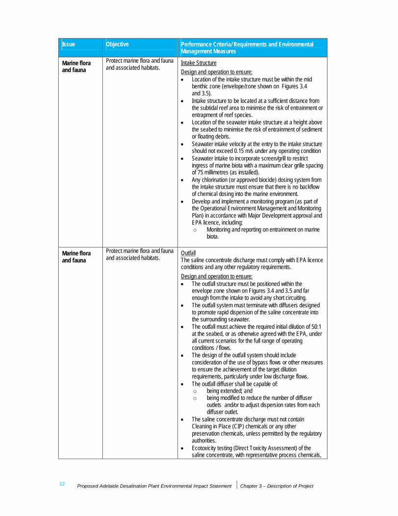
Marine floraand fauna
Protect marine flora and faunaand associated habitats.
Intake StructureDesign and operation to ensure:
Location of the intake structure must be within the midbenthic zone (envelope/zone shown on Figures 3.4and 3.5).Intake structure to be located at a sufficient distance fromthe subtidal reef area to minimise the risk of entrainment orentrapment of reef species.Location of the seawater intake structure at a height abovethe seabed to minimise the risk of entrainment of sedimentor floating debris.Seawater intake velocity at the entry to the intake structureshould not exceed 0.15 m/s under any operating conditionSeawater intake to incorporate screen/grill to restrictingress of marine biota with a maximum clear grille spacingof 75 millimetres (as installed).Any chlorination (or approved biocide) dosing system fromthe intake structure must ensure that there is no backflowof chemical dosing into the marine environment.Develop and implement a monitoring program (as part ofthe Operational Environment Management and MonitoringPlan) in accordance with Major Development approval andEPA licence, including:o Monitoring and reporting on entrainment on marine
biota.
Marine floraand fauna
Protect marine flora and faunaand associated habitats.
OutfallThe saline concentrate discharge must comply with EPA licenceconditions and any other regulatory requirements.Design and operation to ensure:
The outfall structure must be positioned within theenvelope zone shown on Figures 3.4 and 3.5 and farenough from the intake to avoid any short circuiting.The outfall system must terminate with diffusers designedto promote rapid dispersion of the saline concentrate intothe surrounding seawater.The outfall must achieve the required initial dilution of 50:1at the seabed, or as otherwise agreed with the EPA, underall current scenarios for the full range of operatingconditions / flows.The design of the outfall system should includeconsideration of the use of bypass flows or other measuresto ensure the achievement of the target dilutionrequirements, particularly under low discharge flows.The outfall diffuser shall be capable of:o being extended; ando being modified to reduce the number of diffuser
outlets and/or to adjust dispersion rates from eachdiffuser outlet.
The saline concentrate discharge must not containCleaning in Place (CIP) chemicals or any otherpreservation chemicals, unless permitted by the regulatoryauthorities.Ecotoxicity testing (Direct Toxicity Assessment) of thesaline concentrate, with representative process chemicals,

Proposed Adelaide Desalination Plant Environmental Impact Statement Chapter 3 – Description of Project 13
Issue Objective Performance Criteria/ Requirements and EnvironmentalManagement Measures
should be undertaken to confirm species sensitivity and thedilution requirements to protect 95% of species (inaccordance with ANZECC guidelines slight to modifiedecosystems).Develop and implement an Operational EnvironmentalManagement and Monitoring Plan that incorporates amonitoring program in accordance with the MajorDevelopment approval and EPA licensing requirements.The monitoring program shall include:o process monitoring to confirm that performance is
within acceptable range (as supported byenvironmental assessments);
o discharge water quality monitoring;o diffuser performance validation; ando habitat / receiving environment monitoring and water
quality.Demonstrate through modelling and field measurementsthat the outfall design system achieves the required mixingand dispersion requirements.
Figures 3.4 and 3.5 below illustrate the proposed locations of the intake and outfallstructures and the marine zones in which these structures are to be sited. It is importantto emphasise that the environmental objectives and performance criteria listed inTable 3.1 require that the intake and outfall structures are to be located in the midbenthic and deep benthic zones respectively. Chapter 7 provides further detail of thecharacteristics of these zones.
3.1.4 Compliance with Environmental PerformanceCriteria
The proposed Desalination Plant will be designed to achieve the above performancecriteria. SA Water will require the Contractor to have a current and certifiedEnvironmental Management System (EMS) in place, compliant with ISO 14001:2004.Requiring an EMS provides some assurance that the Contractors have a framework inplace to identify environmental impacts associated with their operations and havecompany-enforced strategies to manage and minimise these impacts.
SA Water will also require the Contractor to prepare a comprehensive EnvironmentalManagement and Monitoring Plan (EMMP) which will include the ConstructionEnvironmental Management and Monitoring Plan (CEMMP) and the OperationalEnvironmental Management and Monitoring Plan (OEMMP).
The CEMPP will be developed for the construction of the Desalination Plant. ThisCEMMP will detail environmental risks and associated impacts during theconstruction phase and provide mitigation measures for the Contractor to follow.
The OEMMP will be required for the operation of the proposed Desalination Plant.This OEMMP will identify potential environmental risks and impacts associated withthe Desalination Plant operations and present mitigation measures to minimise oravoid impacts, as well as specify ongoing monitoring requirements.
SA Water and the Contractor will jointly appoint an Independent Verifier for theDesalination Plant. The roles of the Independent Verifier include:

14 Proposed Adelaide Desalination Plant Environmental Impact Statement Chapter 3 – Description of Project
Verifying that the processes employed by the Contractor in the design, construction,commissioning of the works comply with the requirements of the Contract; and
Verifying that the Contractor’s activities and works comply with the requirements ofthe Contract, including verification of milestones in the completion of works.
Proposed Adelaide Desalination Plant Environmental Impact Statement Chapter 3 – Description of Project 15
3.2 Description of Existing Environment3.2.1 Description of the Port Stanvac Site
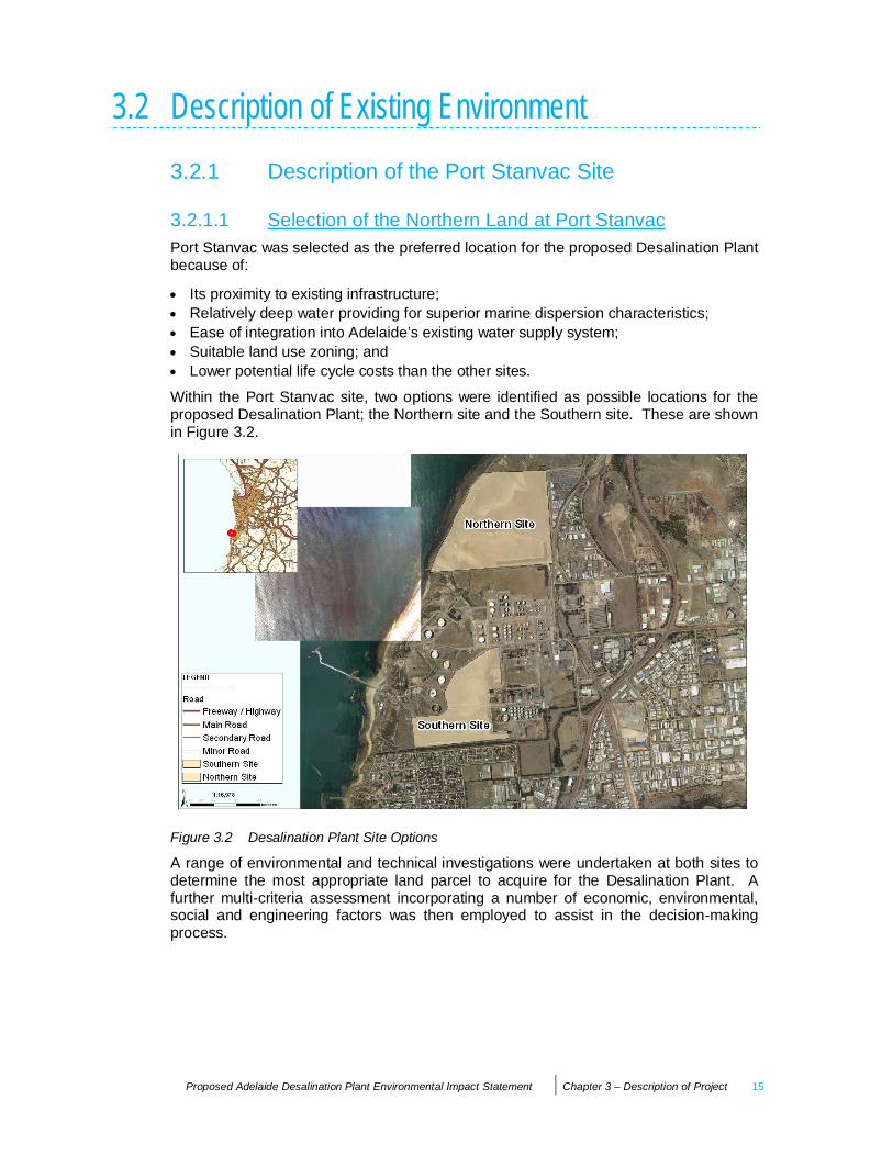
3.2.1.1 Selection of the Northern Land at Port StanvacPort Stanvac was selected as the preferred location for the proposed Desalination Plantbecause of:
Its proximity to existing infrastructure;Relatively deep water providing for superior marine dispersion characteristics;Ease of integration into Adelaide’s existing water supply system;Suitable land use zoning; andLower potential life cycle costs than the other sites.
Within the Port Stanvac site, two options were identified as possible locations for theproposed Desalination Plant; the Northern site and the Southern site. These are shownin Figure 3.2.
Figure 3.2 Desalination Plant Site Options
A range of environmental and technical investigations were undertaken at both sites todetermine the most appropriate land parcel to acquire for the Desalination Plant. Afurther multi-criteria assessment incorporating a number of economic, environmental,social and engineering factors was then employed to assist in the decision-makingprocess.

16 Proposed Adelaide Desalination Plant Environmental Impact Statement Chapter 3 – Description of Project
The following conclusions were made based on the multi-criteria assessment:
Economic – the likely difference in development costs presents nominally a $25million saving for the Northern site option. This excludes remediation costs for eithersite;
Environment (Marine) – results indicate there is an insignificant difference betweenthe Northern and Southern sites in terms of marine biology, seabed topography andwater quality and currents;
Environment (Terrestrial) – the Southern site presents a considerably greater risk forthe management of groundwater contamination. The vegetation assessmentindicates that the Southern site has the greater potential to impact on significant floraand fauna habitat and, as such, the Northern site is preferred;
Heritage – both sites have been subject to an Aboriginal Heritage Survey andmonitoring by the Kaurna people;
Noise – the Northern site has a greater buffer to residential areas; and
Traffic – the traffic report concludes that the Southern site option is marginallypreferred, as it presents less impact to the regional traffic network, including impactson local residents. However, there will be insignificant additional interaction andrisks associated with Mobil’s current operations at the Southern site.
For both the Northern and Southern sites, engineering evaluations were undertaken toassess the impacts and viability of constructing and operating the proposedDesalination Plant over a 20-year horizon. Conceptual plant layouts were developed foreach site that considered numerous factors, including topography, existing vegetation,potential buffers from adjacent land users, visual impacts, operational efficiency, noise,geotechnical conditions, accessibility, location and likely impacts on the terrestrial andmarine environments of the proposed intake and outfall structures.
The outcome of these investigations was that the Northern site at Port Stanvac wasidentified as the most appropriate site for the establishment of the proposedDesalination Plant.
3.2.1.2 Northern Site DescriptionThe Northern site is presently owned by Mobil Oil Australia (‘Mobil’). SA Water iscurrently in negotiations with Mobil to acquire the land. The Northern site comprisesboth terrestrial and marine components. In relation to the terrestrial components, thesite has been disturbed through clearance and historical land use, including croppingand grazing. The Northern site is bounded by Christie Road to the east and anunsealed access road and open (undeveloped) land to the north. Beyond the northernboundary, the land is within the City of Marion council area.
The Northern site comprises two irregular-shaped land parcels along with four regular-shaped land parcels with an approximate total area of 60 hectares of whichapproximately 30 hectares will be required for the Desalination Plant. The land has anotable slope grading from east to west, is free from built-form development, cleared ofnative vegetation and is presently being used for grazing and cropping. The site iscurrently zoned for industrial activities.
The western portion of the Northern site includes the coast and marine environmentwith the western boundary of the subject land extending to the high water mark, whichabuts the coastal cliffs. The coastal cliffs are approximately 30 metres above sea level

Proposed Adelaide Desalination Plant Environmental Impact Statement Chapter 3 – Description of Project 17
and typically form the backdrop to the coastal environment. The Certificates of Titles forthe subject land show a public road reserve located between this land and theforeshore. The Desalination Plant footprint does not encroach onto the road reserve.No Crown Land or coastal reserve exists between this land and Gulf St Vincent while aMarine Restricted Area extends from the high water mark out to Gulf St Vincent for aconsiderable distance (approximately 500 metre radius). There is presently restrictedpublic access along the foreshore and the marine environment.
3.2.1.2.1 Utility ServicesThe existing Port Stanvac facility has a variety of existing services and infrastructure,which may support the proposed Desalination Plant. These services, and the degree ofaugmentation required to support the proposed development, are discussed inChapter 4.
3.2.1.3 Description of Surrounding LocalityThe locality of the Northern site is largely dominated by industrial land uses, withdispersed smaller industrial and commercial activities. The existing (non-operational) oilrefinery is the most dominant feature in the immediate and wider locality. The industrialland use pattern continues to the east of the subject land, with industrial activitiesextending both north-eastwards and southwards along Dyson and Lonsdale Roads andthe railway corridor.
As noted, the northern boundary of the subject site abuts relatively open andundeveloped land and comprises a mix of land within the City of Onkaparinga (zonedIndustry) as well as land within the City of Marion (zoned Landscape (Buffer)).Residential development lies beyond this buffer at a distance of between 350 metres to400 metres from the site’s northern property boundary.
The rail corridor, large open storage areas and industrial land uses extend the entirelength of the eastern side of Christie Road and largely dominate the site’s easternboundary. A 66 kV overhead power line also traverses Christie Road.
18 Proposed Adelaide Desalination Plant Environmental Impact Statement Chapter 3 – Description of Project
3.3 Nature of ProposalAs indicated above, the various components and elements of the proposed DesalinationPlant and marine works, including its location, treatment processes and expected areafootprint, are based on the Concept Design developed for the proposal.
During the development of the Concept Design, options for system design andconstruction have been considered and assessed against SA Water’s environmentaland engineering performance objectives, functional requirements and constraints.Whilst some options present feasible alternatives and are described in some detail,others have not been pursued on the basis that they do not meet environmental and/orengineering performance objectives.
As previously stated, the successful Contractor will undertake the final design of theproposed Desalination Plant within the environmental and engineering objectives andperformance criteria listed in Table 3.1 above.
Management of wastes anticipated to arise from the construction and operation of theproposed Desalination Plant is described in Chapter 9.
3.3.1 Description of Desalination PlantThe proposed Desalination Plant comprises the following key elements:
Seawater intake structure and connecting tunnel/s or pipelines;
Intake pumping station and screening system;
Pre-treatment system and associated buildings;
Reverse osmosis treatment system and associated buildings;
Outfall structure with diffusers and connecting tunnel/s and pipelines;
Post-treatment system and associated buildings; and
Waste treatment area, including solids thickening and dewatering.
In addition, the proposed Desalination Plant will include:
Transfer pump station for pumping desalinated water to the HVWTP. As indicated inChapter 1, this pump station is not part of the Major Development assessmentprocess and has been subject to a separate assessment under Section 49 (CrownDevelopment) of the Development Act 1993;Hardstand areas for unloading and storage of chemicals associated with theDesalination Plant;Electrical substation, power cabling and switchgear for distributing power within thesite;
Energy recovery facility for the saline concentrate prior to its discharge to the Gulf StVincent;Site access roads, internal access roads and parking areas;Stormwater management infrastructure and other buried services across the site;

Proposed Adelaide Desalination Plant Environmental Impact Statement Chapter 3 – Description of Project 19
Site offices and administration buildings, control rooms, laboratory, research anddevelopment test facility, and a visitor education/interpretive centre; andSite landscaping, lighting and security fencing across the site.
Figure 3.3 illustrates the proposed layout of the terrestrial elements of the DesalinationPlant, which are described in further detail in the sections below.
Figure 3.3 Proposed Layout of Desalination Plant.Note: The shaded sections of the buildings show possible expansion layout space.
3.3.1.1 System CapacityThe proposed Desalination Plant will be a reverse osmosis plant with the capacity toinitially supply 50 GL per annum (150 ML of drinking water per day) and withinfrastructure to support future augmentation of up to 100 GL per annum (300 ML ofdrinking water per day). The Desalination Plant would be capable of being expanded tothe ultimate capacity of 100GL per annum without interrupting operation. Major civilworks, such as the intake and outfall structures and conduits have been designed toaccommodate the ultimate capacity of the proposed Desalination Plant at 100GL perannum. All of the studies and investigations undertaken as part of this EIS haveconsidered both 50 GL per annum and up to 100 GL per annum capacity.
A summary of the design flows used for the Concept Design for the intake and outfallstructures is shown in Table 3.2 below.
The Concept Design has assumed a minimum recovery from the reverse osmosismembrane system of approximately 40% of the total flow. This may increase up to 45%in the future.

20 Proposed Adelaide Desalination Plant Environmental Impact Statement Chapter 3 – Description of Project
Table 3.2 Summary of Design Flows for Intake and Outfall.
Raw seawater intake flow(ML per day)
Drinking water produced(ML per day)
Return to outfall flow(ML per day)
383 (note 1) 150 (note 1) 233 (note 1)
765 (note 2) 300 (note 2) 465 (note 2)
77 (minimum operating flow) 30 (minimum operating flow) 47 (minimum operating flow)
Note 1: Raw seawater flow to meet 50 GL per annum capacity.Note 2: Raw seawater flow to meet 100 GL per annum capacity.
3.3.1.2 Plant FootprintThe Concept Design allows for a land area of approximately 20–30 hectares (200,000square metres to 300,000 square metres) to accommodate the proposed development.This includes land for all associated infrastructure and buffer zones, as well asnecessary environmental treatments and safeguards.
In considering the conceptual layout and footprint at the site, a number of technical,social and environmental issues were considered including:
Taking advantage of the natural slope of the land to assist with hydraulic design oftreatment systems to minimise energy consumption and the extent of earthworksrequired for construction of buildings;
Locating noisy components of the Desalination Plant at appropriate buffer distancesfrom residential areas located to the north of the site;
Locating infrastructure to avoid identified and recorded entries for Aboriginal sites (asper the Central Archive);
Locating infrastructure to avoid or minimise disturbance to areas of environmentalsensitivity, including the coastal cliff zone, drainage lines and marine features wherepossible;
Allowing for a nominal 100 metres by 100 metres space (10,000 square metrefootprint) for the proposed new ETSA substation, which will be capable of expansionto support the electrical loads from the proposed Desalination Plant to meet thefuture capacity of up to 100 GL per annum of drinking water; and
Allowing for heavy vehicle access loads and requirements during construction, aswell as chemical, waste and equipment transport vehicles during operation of theDesalination Plant.
3.3.1.3 Intake Pumping Station and ScreeningThe intake system will convey seawater from the intake structure via an intake conduitto the intake pumping station.
Marine material and debris that is able to pass through the coarse screens at the intakestructure will need to be removed prior to the pre treatment process. The ConceptDesign has proposed the use of rotating band screens for this purpose, located in theinlet chamber/pump sump prior to the intake pumps. Alternative screening devices may

Proposed Adelaide Desalination Plant Environmental Impact Statement Chapter 3 – Description of Project 21
be pursued during the final design, subject to meeting the overall environmental andengineering performance objectives. Waste management, including screenings, isdescribed in Chapter 9.
A pump station will pump the screened seawater to the pre-treatment plant, locatedwithin the Desalination Plant footprint. During the Concept Design, a number oflocations for the intake pump station were considered, including on the foreshore area(if tunnelling was not employed) or inside a shaft to the intake tunnel (if tunnelling wasemployed). The Concept Design has been based on locating the pump station insidethe tunnel shaft behind the cliff.
Based on the environmental performance requirements the intake seawater pumpstation will not be located within the cliff zone or the sensitive intertidal reef zone, whichprecludes the foreshore option.
Figures 3.4 and 3.5 illustrate the proposed location of the intake and outfall structures inrelation to the marine zones adjacent the Desalination Plant site.
Figure 3.4 Proposed Envelope of Intake and Outfall Structures. Overlaid on DEH Habitat Map(DEH 2008 b).

22 Proposed Adelaide Desalination Plant Environmental Impact Statement Chapter 3 – Description of Project
Figure 3.5 Marine Zones Adjacent to the Plant Site.
3.3.1.4 Pre-Treatment SystemThe purpose of the pre-treatment process is to remove suspended solids, oil andgrease or other matter that could block, damage or significantly foul the reverseosmosis membranes.
The pre-treatment process incorporates a number of stages, similar to that used in theconventional treatment of surface waters for drinking supplies.
A number of engineering options for the pre-treatment stage may be pursued and thefinal selection for the detailed design would be determined by factors such as rawseawater quality, available land area and filtered seawater quality requirements.
Two pre-treatment systems were considered in developing the Concept Design asfollows:
Conventional treatment, which includes chemical coagulation, clarification and mediafiltration; and
Membrane filtration, which involves the use of synthetic polymer filters that act as aphysical barrier, capable of removing particles as small as 0.02 microns.
The Concept Design has been based on the development of a conventional treatmentdesalination plant. The reason for this is that the use of membranes for pre-treatment isrelatively new and the long-term reliability and performance for a desalination plant ofthe proposed size is not yet to be proven. This has allowed for a conservative estimateof the proposed Desalination Plant’s footprint due to the larger size of a conventionaltreatment plant as opposed to a membrane filtration plant. The final design may utilisemembrane or other alternatives that may help reduce the proposed Desalination Plant’soverall footprint whilst meeting the specified performance and durability requirements.
Proposed Adelaide Desalination Plant Environmental Impact Statement Chapter 3 – Description of Project 23
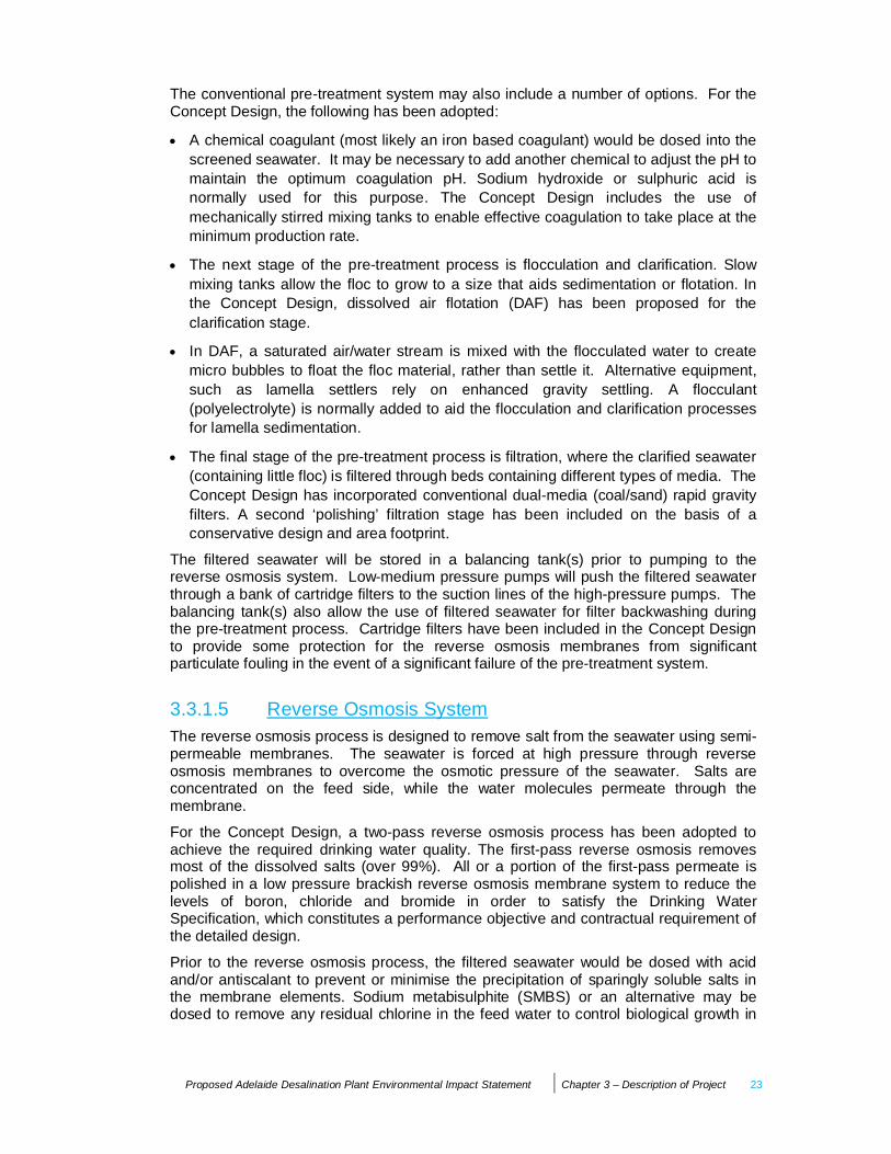
The conventional pre-treatment system may also include a number of options. For theConcept Design, the following has been adopted:
A chemical coagulant (most likely an iron based coagulant) would be dosed into thescreened seawater. It may be necessary to add another chemical to adjust the pH tomaintain the optimum coagulation pH. Sodium hydroxide or sulphuric acid isnormally used for this purpose. The Concept Design includes the use ofmechanically stirred mixing tanks to enable effective coagulation to take place at theminimum production rate.
The next stage of the pre-treatment process is flocculation and clarification. Slowmixing tanks allow the floc to grow to a size that aids sedimentation or flotation. Inthe Concept Design, dissolved air flotation (DAF) has been proposed for theclarification stage.
In DAF, a saturated air/water stream is mixed with the flocculated water to createmicro bubbles to float the floc material, rather than settle it. Alternative equipment,such as lamella settlers rely on enhanced gravity settling. A flocculant(polyelectrolyte) is normally added to aid the flocculation and clarification processesfor lamella sedimentation.
The final stage of the pre-treatment process is filtration, where the clarified seawater(containing little floc) is filtered through beds containing different types of media. TheConcept Design has incorporated conventional dual-media (coal/sand) rapid gravityfilters. A second ‘polishing’ filtration stage has been included on the basis of aconservative design and area footprint.
The filtered seawater will be stored in a balancing tank(s) prior to pumping to thereverse osmosis system. Low-medium pressure pumps will push the filtered seawaterthrough a bank of cartridge filters to the suction lines of the high-pressure pumps. Thebalancing tank(s) also allow the use of filtered seawater for filter backwashing duringthe pre-treatment process. Cartridge filters have been included in the Concept Designto provide some protection for the reverse osmosis membranes from significantparticulate fouling in the event of a significant failure of the pre-treatment system.
3.3.1.5 Reverse Osmosis SystemThe reverse osmosis process is designed to remove salt from the seawater using semi-permeable membranes. The seawater is forced at high pressure through reverseosmosis membranes to overcome the osmotic pressure of the seawater. Salts areconcentrated on the feed side, while the water molecules permeate through themembrane.
For the Concept Design, a two-pass reverse osmosis process has been adopted toachieve the required drinking water quality. The first-pass reverse osmosis removesmost of the dissolved salts (over 99%). All or a portion of the first-pass permeate ispolished in a low pressure brackish reverse osmosis membrane system to reduce thelevels of boron, chloride and bromide in order to satisfy the Drinking WaterSpecification, which constitutes a performance objective and contractual requirement ofthe detailed design.
Prior to the reverse osmosis process, the filtered seawater would be dosed with acidand/or antiscalant to prevent or minimise the precipitation of sparingly soluble salts inthe membrane elements. Sodium metabisulphite (SMBS) or an alternative may bedosed to remove any residual chlorine in the feed water to control biological growth in
24 Proposed Adelaide Desalination Plant Environmental Impact Statement Chapter 3 – Description of Project
the intake system. Chlorine attacks and degrades the desalination capability of thin-filmcomposite reverse osmosis membranes. The removal of free chlorine prior to thereverse osmosis membrane system is therefore of critical importance. Adjustment ofpH, if required, is normally achieved through the use of sulphuric acid.
The first pass reverse osmosis membranes will produce a saline concentrate stream,which will be discharged to the ocean via the outfall (see below). This stream wouldalso contain traces of chemicals added during the treatment process. The reject streamfrom the second pass is of relatively low salinity and can be returned to the head of thereverse osmosis process to increase the overall recovery and efficiency of the process.An alternative would be to discharge this stream to the outfall if it complies with EPAdischarge criteria.
In the Concept Design, the first pass reverse osmosis plant will be configured to have atrain size of 15 ML/d, requiring approximately 10 trains to produce the 150 ML/d outputfrom the initial phase of the project (or approximately 20 trains to produce 300 ML/d).The membranes to be used comprise thin film composite spiral wound membranesdeveloped for seawater desalination. The main components of the reverse osmosistrains include high pressure pumps, energy recovery devices, the first pass reverseosmosis membranes, saline concentrate line, permeate tank, booster pumps for thesecond pass system, second pass reverse osmosis membranes and second pass rejectstream.
The first pass concentrate will be fed to energy recovery devices (ERDs) before beingdischarged via the outfall. The ERDs facilitate transfer of pressure energy from theconcentrate to the incoming reverse osmosis feed water.
3.3.1.6 Post-Treatment SystemPermeate from the reverse osmosis process will have very low mineral and alkalinitycontent and would therefore be corrosive to materials such as concrete in the TransferPipeline and reticulation pipe-work, as well as domestic fittings containing copper orbrass. The permeate is rendered non-corrosive and suitable for drinking via the additionof calcium salts, such as lime (or hydrated lime) and carbon dioxide. The ConceptDesign is based on the use of lime and CO2, although alternatives such as calcite(marble chip) filtration may be considered.
Following remineralisation, the treated water will be dosed with fluoride (added ashydro-fluorsilicic acid) to satisfy the requirements of the Department of Health, andchlorine to ensure disinfection integrity.
3.3.1.7 Treated Water StorageA covered treated water storage tank(s) will be constructed on-site to temporarily storethe water prior to pumping to the HVWTP. A minimum storage capacity of 50 ML hasbeen adopted for the Concept Design. This will provide up to 8 hours storage (for the50 GL per year capacity), providing some buffer against variations in the pumping flowinto and out of the storage with varying demands in the Happy Valley system.
3.3.1.8 Plant Control SystemThe proposed Desalination Plant will have a comprehensive computer-basedmonitoring and control system.

Proposed Adelaide Desalination Plant Environmental Impact Statement Chapter 3 – Description of Project 25
The control system will enable full automatic control and operation of the DesalinationPlant and permit the operator to remotely monitor and to control discrete aspects of theDesalination Plant.
The control system will be capable of expansion to meet the future capacityrequirements, with minimal disruption to Desalination Plant operation.
3.3.1.9 Buildings and Civil StructuresThe buildings and civil structures will comply with architectural requirements as outlinedby SA Water. These include:
Being consistent with an overall conceptual scheme to achieve an integrated andwell ordered presentation;
Being proportioned to achieve an aesthetically pleasing appearance;
Maintaining order and purpose in the location and number of rooftop features, suchas flues, skylights, cowls and vents;
Meeting the minimum energy efficiency requirements described in the Building Codeof Australia;
Taking account of the visual impact assessment and environmental performanceobjectives and criteria for the project; and
Being designed to maximise the use of natural lighting and ventilation.
The inlet chamber, flocculators and DAF tanks, filters and treated water storage tanks inthe Concept Design are of reinforced concrete construction. In general, buildings arelikely to be clad, steel framed structures on concrete foundations. Specific buildings,such as the control/administration, visitor centre and main switchgear building may beof masonry construction. The buildings making up the Desalination Plant will berequired to meet proposed architectural criteria.
Concrete works in contact with seawater will require cathodic protection to meet thefunctional requirements for durability. Proposed intake and outfall structures and wetareas of the intake pumping station will require induced current cathodic protection.
The site will require cut and fill earthwork operations, including excavation for inter-process pipe-work, construction of partially buried structures, levelling of steep areas ofthe site and for road embankments and drainage.
The site will be incorporate a security system that includes a security fence, secureaccess, site CCTV and building intruder detection.
3.3.1.10 Chemical StorageA range of treatment chemicals will be required to be stored at the proposedDesalination Plant site.
The Concept Design assumes that a ferric-based coagulant will be used for pre-treatment, along with polyelectrolyte and sulphuric acid/caustic soda for pH adjustment.Bulk storage tanks will be provided, in accordance with relevant legislation andprotocols, for the acid, liquid coagulant and caustic soda. A dry store and polyelectrolytepreparation kit will be provided for the solid polymer and chemical dosing will be viaduty/standby dosing pumps.
26 Proposed Adelaide Desalination Plant Environmental Impact Statement Chapter 3 – Description of Project
Measures to protect the environment from potential spillage of chemicals will beincorporated within the final design in accordance with all relevant legislation andstandards. The Contractor will be required to develop and implement an OperationsManagement Plan for the control of chemicals which would include contingency plansand incident response procedures.
3.3.2 Description of Marine Structures
3.3.2.1 GeneralThe marine structures for the proposed Desalination Plant comprise the intakestructure, designed to reduce the entrapment or entrainment of marine biota, the outfallstructure (diffuser) designed to diffuse the saline concentrate to the marineenvironment, and the intake and outfall conduits to convey seawater to the DesalinationPlant and to return saline concentrate to the outfall structure.
3.3.2.2 Seawater Intake StructureThe seawater intake structure will draw in seawater through screening grills and into theintake conduit (refer Figure 3.4). For the Concept Design, the intake system has beendesigned to operate by gravity with the intake structure located approximately 1.0 to1.5 kilometres offshore, at approximately 15 to 18 metres depth to seabed. For theConcept Design, the intake conduit has a nominal diameter of approximately2.5 metres.
The selection of the intake zone has included consideration of a range of factorsincluding depth, constructability, hydraulics and the outcomes of investigations into themarine ecology at the site. The identified intake zone is to be located beyond thesubtidal reef in the mid benthic zone, which comprises predominantly bare sand withlow species diversity (see Chapter 7 and SARDI 2008a). The location of the intakestructure must avoid short-circuiting of the saline concentrate from the outfall diffusersection.
3.3.2.2.1 Entrapment and Entrainment ControlThe intake structure will be designed to reduce the risk of entrapment and entrainmentof marine biota through the inclusion of a screen/grill and by limiting the intake velocityto enable mobile marine organisms to swim away from the intake structure. A grillspacing of 75 millimetres (when clean) has been adopted for the Concept Design thathas been included as part of the project performance criteria. To reduce the potential forentrainment, a maximum flow velocity of 0.15 m/s at the intake grill has been adoptedfor the project performance requirements. This velocity is in line with industry standardsand has been based on a study of background sea current velocity profiles andtransient variation, together with consideration of the nature of expected flora and faunaand proximity to their marine habitat. The final design will be required to comply withthese specifications.
For the Concept Design, the intake structure has been located approximately 3 to4 metres above the seabed to reduce the ingress of sediment, marine debris, andbenthic marine biota, including eggs and larvae. This height is consistent with seawaterintakes of other Australian desalination projects, and will ensure that there is a cleardepth of water above the intake structure of 10 to 12 metres under various tidalconditions. This will reduce risks associated with intake water quality, such as sedimentplumes following storm events, or navigation of marine vessels.
Proposed Adelaide Desalination Plant Environmental Impact Statement Chapter 3 – Description of Project 27
Marine material and debris that is able to pass through the coarse screening at theintake structure (eg seaweed and shells) will be removed by fine screening at the intakepumping station as described in Section 3.3.1 and Chapter 7.
3.3.2.2.2 Disinfection System at the IntakeThe intake structure in the Concept Design is approximately 6 to 7 metres in diameterand has been designed with a closed lid and sloping grills, similar to a funnel.
The Concept Design allows for a chlorine dosing system to be installed in the intakeconduit to control marine growth. The chlorination system has been configured at thebase of the structure to prevent the backflow of chlorine solution into the marineenvironment, even during sudden power failure during a dosing event.
The intake chlorination system would operate in intermittent ‘shock’ dosing mode, withthe seawater de-chlorinated prior to the reverse osmosis system. The chlorine deliveryline could be run either within or external to the intake conduit. For the Concept Design,an external line encased in a second pipe with a leak detection system was adoptedrather than an internal line, as this would restrict the ability to physically clean the intakeusing mechanical means, if necessary.
Alternative disinfection chemicals may be considered in the final design provided theiruse complies with the environmental and engineering performance objectives of theADP.
3.3.2.3 Outfall Structure (Diffuser)The desalination process generates a saline concentrate stream from the reverseosmosis process. The saline concentrate would be approximately 1.6 to 1.8 times thesalinity of the background seawater, and contains trace amounts of chemicals addedduring the desalination process. The saline concentrate would be returned to the seavia a gravity-driven outfall. In the Concept Design, the outfall pipeline is proposed tohave an approximate nominal internal diameter of 2.0 metres and extend approximately1.5 to 2.0 kilometres offshore.
The outfall location is situated within the mid to deep benthic zones. Selection of thiszone was based on ensuring that the discharge does not impact upon the biologicallyimportant inter tidal and sub tidal reef communities, and is sufficiently separated fromthe seawater intake to minimise the risks of flow short-circuiting to the intake.
Due to the higher salinity of the discharge, it is important that the saline concentrate isreturned to the sea in such a way as to ensure that it is dispersed rapidly andcompletely with the background seawater. This mixing process is achieved with adiffuser structure that is designed to break up the flow of saline concentrate into smallstreams and ‘jet’ these streams into a large volume of surrounding seawater withsufficient velocity to mix and disperse the saline concentrate, and achieve target dilutionrequirements prior to the discharge reaching the seabed. The target initial dilution is50:1 at the seabed under all operating and tidal current conditions and the final designwill be required to comply with this specification.
For the Concept Design, the diffuser comprises numerous small ‘ports’ and incorporatesa nominal 1.5 metre diameter pipe up to 250 metres in length submerged below theseabed. Vertical riser pipes (approximately 0.2 metres in diameter) protrude through theseabed to about 1 metre above the seabed, where the diameter reduces to that of theexit ports angled upwards at approximately 60o to the horizontal.

28 Proposed Adelaide Desalination Plant Environmental Impact Statement Chapter 3 – Description of Project
The exit velocity of the saline concentrate is considerably higher than the backgroundseawater. As the saline concentrate ‘jet’ mixes rapidly with the ambient seawater, the jetvelocity decreases and its trajectory bends toward the seabed. At this point, the initialdischarge characteristics cease to influence mixing and the ambient currents andturbulence near the seabed control subsequent dispersion. The subsequent plume isslightly heavier than the ambient seawater and tends to flow down towards the deeperoffshore water, while being transported by the typically shore-parallel currents of Gulf StVincent.
The final diffuser design may include variations to the concept. Such variations wouldneed to demonstrate that they meet SA Water’s environmental performance objectivesand achieve the minimum dilution requirement of 50:1.
3.3.2.4 Intake and Outfall ConduitsThe Concept Design for the proposed intake and outfall conduits considered threepossible options based on construction methodology. These options included:
Option 1 – Seabed Pipelines – this involves construction via trenched pipelines fromthe Desalination Plant to the intake structure and diffusers offshore.
Option 2 – Full Tunnel(s) – this involves the construction of a tunnel(s) over the fulldistance to the intake structure and diffusers offshore.
Option 3 – Combined Pipe-Jacked Tunnel(s) and Seabed Pipelines (hybrid option) –this involves the construction of a tunnel(s) to beyond the shore break (near the rockshelf extent), followed by trenched pipelines to the intake structure and diffusers.
A marine environmental risk and impact assessment concluded that the environmentalissues related to the seabed pipeline (Option 1), particularly those associated withconstruction through the cliff, intertidal and subtidal areas, were too significant toproceed. Therefore, this option was not pursued further.
The final design may include variations to the concept options, such as a combinedpipe-jacked and seabed pipeline. Any variations would need to demonstrate that theysupport the environmental performance objectives and result in an improvedenvironmental outcome.
3.3.2.4.1 Full Tunnel OptionThe full tunnel option includes the following key components:
The construction of a deep shaft adjacent to the proposed Desalination Plant toenable construction of the tunnel(s);
An intake pumping station located within the deep shaft; and
Riser structure(s) from the end of the tunnel(s) upwards to the pipelines, located onthe seabed, including an excavated cross-connection below the seabed.
Figure 3.6 illustrates the full tunnel option and the likely impacts of this option duringconstruction and operation of the proposed Desalination Plant.

Proposed Adelaide Desalination Plant Environmental Impact Statement Chapter 3 – Description of Project 29
Figure 3.6 Full Tunnel Option.
3.3.2.4.2 Hybrid Tunnel OptionThe hybrid tunnel option includes a pipe-jacked tunnel past the intertidal zone so as notto impact on the intertidal environment. The hybrid tunnel is then trenched for theremainder of its length (see Figure 3.7).
Figure 3.7 Hybrid Tunnel Option.
For both tunnelling options, the tunnel sections would be constructed by excavating adeep shaft on land, into which a tunnel-boring machine (TBM) would be placed toexcavate and support the tunnels.
At the end of the tunnel sections, the conduits would rise to the seabed using a riserstructure. This is a vertical shaft drilled or cut from a stationary jack-up barge (or similarequipment) above the tunnel, downwards to the tunnel. The excavation of the shaftmay be undertaken underwater but could be achieved in a cofferdam if required.

30 Proposed Adelaide Desalination Plant Environmental Impact Statement Chapter 3 – Description of Project
From the intake and outfall conduit riser structure(s), pipelines would be laid andbackfilled in trenches out to the intake and diffuser locations. One method ofconstruction includes assembling sections on-shore before being floated into positionoffshore and lowered into place. Other options may be employed, however.
Construction methods for pipelines buried within the seabed involve dredging andentrenching, which will be required to comply with relevant approvals. For the ConceptDesign, burying and armouring was included to protect against scour and damage withminimum cover over the conduit of 0.5 metres.
3.3.3 Waste ManagementThe Desalination Plant generates a number of waste streams from the treatmentprocess that will require appropriate management and these are discussed further inChapter 9. Wastes from operation of the Desalination Plant relate to the following:
Intake screenings;
Pre-treatment wastes;
Antiscalants;
Clean-in-place (CIP) chemicals;
Membrane preservative solutions;
Membrane flushing solutions; and
Other general wastes.
3.3.4 Water Quality Monitoring SystemsContinuous monitoring of water quality will be carried out at specified locations toenable the proposed Desalination Plant to be operated in a manner that safeguardspublic health, ensures no damage to equipment, protects the environment and enablesthe plant to deliver drinking water at the required water quality.
Analytical instrumentation will be connected to the site Supervisory Control And DataAcquisition (SCADA) system to alert operations staff in the event of one or moreparameters exceeding preset limits.
The following is a summary of locations and parameters to be monitored:
Entrance to intake pumping stations:
o Total petroleum hydrocarbons;o Chlorine residual (if chlorination of intake system is adopted).
Entrance to pre-treatment facilities:
o Turbidity;o pH;o Conductivity;o Temperature;o Chlorine residual (and/or ORP);o Dissolved oxygen.
Entrance to reverse osmosis plant:
o Turbidity

Proposed Adelaide Desalination Plant Environmental Impact Statement Chapter 3 – Description of Project 31
o pHo Cl2 residualo Conductivityo Silt Density Indexo Oxidation Reduction Potential.o Boron (first pass permeate and final permeate before post-treatment).
Entrance to delivery point:
o Turbidityo Conductivityo Temperatureo pHo Fluorideo Chlorine residualo Boron
Outfall system – discharge to sea:
o Conductivityo Flow rateo Temperatureo pHo Dissolved oxygeno Turbidityo Chlorine residual or ORP equivalent.
Manual sampling will also be required at specified locations.
3.3.5 Electricity Supply and Energy RequirementsThe Concept Design includes infrastructure that needs to be installed to secure powersupply rated at 50 MW for the 50 GL per annum Desalination Plant and 100 MW for the100 GL per annum Desalination Plant. The infrastructure sizing allows for transientpeaks, safety and system protection and so is significantly greater than the anticipatedactual usage of electricity for operation of the Desalination Plant at full capacity.
Electricity for the proposed Desalination Plant will be supplied from the 66 kV electricitygrid. A new substation will be constructed on-site to accommodate the large powerbase required. This substation will ensure the site supply voltage of 11 kV.
Temporary construction power supply for construction activities will also be requiredand arrangements are being put in place with ETSA for this purpose.
A description of the electricity supply and associated infrastructure proposed for theDesalination Plant is presented in Chapter 6.
3.3.5.1 Specific Energy ConsumptionThe specific energy consumption of the proposed Desalination Plant has been specifiedto achieve better than 4.5 kWh per KL of drinking water produced.
The specific energy consumption requirement of the Desalination Plant is based on aspecified range of seawater temperature, total dissolved solids (TDS) and determinedon the basis of national and international benchmarks. This is subject to confirmation bythe Contractors.
32 Proposed Adelaide Desalination Plant Environmental Impact Statement Chapter 3 – Description of Project
3.3.5.2 Backup PowerThe Concept Design allows for backup power in the form of diesel generation to beprovided for essential services, including ensuring ongoing operation of a batterypowered uninterrupted power supply (UPS) for critical plant control systems andinstrumentation.
3.3.5.3 Energy RecoveryIn addition to the energy recovery devices that will recover energy from the first pass ofthe reverse osmosis system, investigations have been undertaken to determine thefeasibility of installing a hydropower device to recover energy from saline concentrateprior to entering the outfall conduit, taking advantage of the height of the DesalinationPlant site. There are however competing requirements to discharge energy as a certainamount is required to assist in the dispersion and mixing of the saline concentrate as itenters the Gulf St Vincent.
Any surplus energy recovered would be used on site for ancillary services, reducing theenergy required from grid.

Proposed Adelaide Desalination Plant Environmental Impact Statement Chapter 3 – Description of Project 33
3.4 Management ArrangementsA number of design, construction and operational aspects of the proposed developmentwill not be fully known until the final design has been completed. SA Water hasproposed a set of environmental and engineering criteria to mitigate these effects(particularly for nearby communities likely to be affected by the construction andoperation of the Desalination Plant) and will continue to consult with the EPA to ensureregulatory compliance.
SA Water will require the Contractor to have a current and certified EnvironmentalManagement System (EMS) in place, compliant with ISO 14001:2004 within theircompany structure. Requiring an EMS will help ensure the Contractor has identifiedenvironmental impacts associated with their operations and have company-enforcedstrategies to minimise and manage impacts as a result of their activities.
Additional information relating to management arrangements is given in Chapter 4.
3.4.1 Design ManagementThe Contractor will develop a tender design and is also required to submit draftmanagement plans prior to award of a contract, including a design management plan.
The required design and documentation process to be followed by the Contractor will beprescribed in the Contract and allows for design development workshops and designreview. The design report is to incorporate a sustainability plan, durability plan, riskassessment and include drawings and other descriptive information.
3.4.2 Site Management and ConstructionThe Contractor will be required to develop a comprehensive suite of managementplans. These include a Construction Environmental Management and Monitoring Plan(CEMMP) that will be developed for the construction of the Desalination Plant. Thesemanagement plans will detail environmental risks and associated impacts as well asprovide mitigation measures for the Contractor to follow.
3.4.3 Operation and MaintenanceA detailed Operational Environmental Management and Monitoring plan (OEMMP) willalso be required for the operation of the Desalination Plant. This plan will be developedto identify potential environmental risks and impacts associated with the DesalinationPlant operations and specify mitigation measures to minimise impacts, as well asongoing monitoring requirements.
3.4.4 Plant ReliabilityA key element of the system design and layout is reliability of the plant. Keyrequirements for attaining an appropriate level of service and availability include:
The system shall be permitted to be out of operation for any unplanned reason for aperiod not exceeding seven days in a 12-month period (other than intentionaloutages);

34 Proposed Adelaide Desalination Plant Environmental Impact Statement Chapter 3 – Description of Project
The system shall be permitted to be out of operation for planned maintenance for aperiod not exceeding 14 days cumulative in a 12-month period, providing theoutages occur during July to September; and
The system shall also be permitted to be partially out of operation (i.e. reduced watersupply to HVWTP) for planned maintenance by prior written agreement with SAWater.
The unplanned outages do not include force majeure incidents; however they doinclude potential plant shutdowns during foreseen natural events, such as dodge tides.

Proposed Adelaide Desalination Plant Environmental Impact Statement Chapter 3 – Description of Project 35
3.5 Decommissioning3.5.1 Permanent DecommissioningAt some stage it may be necessary to permanently decommission the proposedDesalination Plant. Permanent dismantling of the plant, equipment, buildings andinfrastructure would be required if the plant has either expended its useful life orcircumstances arise where it is no longer required into the long term.
Permanent decommissioning is a separate matter to “mothballing” of the plant, whichmay be necessary in circumstances where it is foreseeable that the plant could berequired in the future.
The proposed Desalination Plant and supporting infrastructure is being engineered tohave an operational for 25 - 100 years. Civil assets such as the tunnels, shafts, buriedpipelines and piles will need to be reconstructed or refurbished after approximately 100years. Assets such as concrete structures, buildings, intake and outfall pipelines, andmechanical and electrical assets are expected to perform for approximately 20 to 50years. These assets will be replaced during the life of the Desalination Plant as theybecome inoperable or as technologies advance.
3.5.2 Decommissioning PlanA detailed decommissioning plan would be required to be developed prior to anydecommissioning of Plant infrastructure. This plan would be in accordance withstandard industry decommissioning procedures and the requirements of the appropriateauthorities.
All surface equipment and structures will be removed. The marine conduits will be leftand filled with sand. The Intake structure will be removed.