proposed new ska offices in black river park, observatory · 2019-10-28 · 1.1 principal,...
TRANSCRIPT

SPECIFICATION AND PROVISIONAL BILLS OF QUANTITIES FOR THE
ELECTRICAL INSTALLATION AT
PROPOSED NEW SKA OFFICES IN BLACK
RIVER PARK, OBSERVATORY
FOR TOWER BRIDGE SPECIAL PROJECTS
TENDER CLOSING TO BE CONFIRMED BY PRINCIPAL AGENT
Employer SKA
Architect Tower Bridge Special Projects
Project Manager Tower Bridge Special Projects
Consulting Engineers AOCon Consulting Engineers
March 2018
Tel +27 (0)21 276-2222
AOCon Consulting Engineers (Pty) Ltd
PO Box 1680
Milnerton
7435

SKA Electrical Installation
Table of contents
Table of contents
Notes To Tenderers ................................................................................................................................................................... 1
Principal Contract Preliminaries ................................................................................................................................................. 2
Main Contractor Specific Conditions Of Contract ...................................................................................................................... 4
General Electrical Specification ................................................................................................................................................. 6
Detailed Technical Specification .............................................................................................................................................. 18
Bills Of Quantities .................................................................................................................................................................... 23
Schedule Of Returnable Items ................................................................................................................................................. 35
Schedule Of Drawings ............................................................................................................................................................. 53
Project Programme .................................................................................................................................................................. 55

SKA Electrical Installation
Page 1 of 48
PART 1
NOTES TO TENDERERS

SKA Electrical Installation
Page 2 of 48
Part 1 Notes to tenderers 1. Bills of Quantities
This document comprises Notes to Tenderers, Specifications, Preliminaries applying to the whole of the works and Provisional Bills of Quantities and is hereinafter referred to as “The Bills of Quantities”.
2. Contract Documentation
The Contract Documents consist of the Drawings listed herein, Agreement and Schedule of Conditions of Building Subcontract (Nominated/Selected Subcontract), these Conditions of Contract and Specification containing all modifications thereof as incorporated in the documents before the signing of the Contract takes place. These Contract Documents supersede all enquiries, proposals, agreements, negotiations and commitments, whether written or verbal, prior to the date of execution of this Contract. Tenderers shall be deemed to have inspected and be fully acquainted with all Contract and the extent of the Works and Subcontract Documents prior to the submission of Tenders.
3. Project General Information
Project Name: Electrical Installation at Proposed New Offices for SKA Site Address Black River Park North, 6 Fir Street, Observatory. Erf 163099 Employer SKA Architect Tower Bridge Special Projects Windermere House, Portswood Ridge, Portswood Road, V&A Waterfront 8000 Project Managers Tower Bridge Special Projects Windermere House, Portswood Ridge, Portswood Road, V&A Waterfront 8000 Consulting Electrical Engineers AOCon Consulting Engineers PO Box 1680 Milnerton 7435
4. Scope of Works The scope of the works will include, but not be limited, to the following: Supply and erection of the electrical installation, including preparation of shop drawings, procurement, fabrication, painting of surface finishing, transport, loading and offloading, storing, hoisting, scaffolding, labour, supervision, equipment, tools, and such other items of expense necessary to complete the installation to the Engineer's satisfaction.
5. Drawings
The drawings as scheduled in part 8 of this document form an integral part of this specification and are to be read in conjunction with this document.
6. Principal Contract
The successful electrical contractor shall enter into a selected sub contract with the awarded Principal Contractor, and as such the same conditions of contract that are applicable to the main contractor will be applicable to the electrical contractor.
7. Programme
The construction programme is included as part 9 of this contract document.

SKA Electrical Installation
Page 3 of 48
FORM OF TENDER
FIXED PRICE CONTRACT
This document is for use with JBCC PRINCIPAL, NOMINATED/SELECTED AND MINOR WORKS AGREEMENTS
Published prior to the introduction of the “Contract Data” forms
PROJECT SKA Electrical Installation
PRINCIPAL AGENT or AGENT Tower Bridge Special Projects
EMPLOYER SKA
TENDERER
WORKS DESCRIPTION
Electrical Installation FILE CODE P202
TENDER CLOSING DATE TBA TIME TBA
prepared by the JOINT BUILDING CONTRACTS COMMITTEE Inc
RECOMMENDED BY THE JBCC CONSTITUENTS Association of Contract Project Managers
Association of South African Quantity Surveyors Master Builders South Africa
South African Association of Consulting Engineers South African Institute of Architects
South African Property Owners Association Specialist Engineering Contractors Committee

SKA Electrical Installation
Page 4 of 62
FORM OF TENDER in terms of a: Principal Building Agreement (yes/no)
N/S Subcontract Agreement (yes/no)
Minor Works Agreement (yes/no)
Principal Agent: Tower Bridge Special Projects
Street Address: Windermere House, Portswood Ridge, Portswood Road, V&A Waterfront, 8000 Tel: +27(0)21 405-0220 E-mail: [email protected]
Employer: SKA
[N/S only] Contractor:
Tenderer :
Postal Address:
Tel: E-mail:
Project:
1.0 CONDITIONS OF TENDER
1.1 PRINCIPAL, NOMINATED/SELECTED AND MINOR WORKS AGREEMENTS 1.1.1 The successful tenderer will be appointed in terms of the JBCC Principal Building Agreement, JBCC N/S
Subcontract Agreement or JBCC Minor Works Agreement
1.1.2 Additions and alterations to such agreement are clearly detailed in the schedule of the agreement
1.1.3 All pre-tender information is set out in the Schedule. Variables requiring selection by the tenderer are to be clearly marked for later inclusion in the Schedule
1.1.4 Any conditions or qualifications that are appended by the tenderer, which are at variance with the conditions in this or the tender enquiry document, may invalidate the submitted tender
1.1.5 Details of the amount of item 2.4.2 of tender sum are to be clearly designated in the tender documentation provided by the principal agent or agent
1.1.6 This tender is to be submitted to the principal agent or agent at the street address stated above before the tender closing date and time stated on the cover hereof
1.1.7 Tenders will be opened in public directly after the stated closing time. Only the total tender sum as stated in 2.4.5 of each tender will be announced
1.1.8 The lowest or any tender will not necessarily be accepted
1.2 NOMINATED / SELECTED SUBCONTRACT AGREEMENT ONLY 1.2.1 The contractor has been or will be appointed in terms of the JBCC Principal Building Agreement
1.2.2 Where the tenderer is advised of the appointment of the contractor after submission of this tender, the tenderer shall be entitled to make reasonable objection to being appointed by the contractor
1.2.3 This tender is submitted to the principal agent or agent who is authorised in terms of the Principal Building Agreement to instruct the contractor to appoint the successful tenderer as a nominated/selected subcontractor
X

SKA Electrical Installation
Page 1 of 56
2.0 THE TENDER
2.1 By the submission of this tender to the employer the tenderer offers and agrees to contract for, execute and complete the works/subcontract works for the tender sum as stated below
2.2 This tender shall remain in full legal force for forty-five (45) calendar days from the tender closing date in the case of Principal or Nominated/Selected Contracts and thirty (30) calendar days for Minor Works Contracts. The tenderer accepts liability for damages as may be suffered by the employer should the tender validity period not be honoured
2.3 This tender takes into account the documents listed hereunder or as per the attached addendum by the principal agent or agent for the purpose of preparing and submitting this tender
Document list or addendum identification None besides this document.
2.4 TENDER SUM COMPILATION Amount
2.4.1 Tenderer’s work including Prime Cost and Provisional Amounts
2.4.2 Budgetary allowances [amount stated by the principal agent / agent]
2.4.3 SUB TOTAL
2.4.4 Add tax on 2.4.3
2.4.5 TOTAL TENDER SUM inclusive of tax
Tender Sum in words
2.5 TENDERER’S SELECTIONS (Fill in Yes, No, Nil as appropriate. Do not leave blanks)
Selection Item PBA N/S Minor Addendums, No/s, Marked
Preliminaries Payment Alternative A
Alternative B
Adjustment Alternative A
Alternative B
Security Variable construction guarantee
Fixed construction guarantee
Retention (Payment reduction)
# Advance payment guarantee (Amount)
# Payment guarantee (Amount)
# These guarantees are not applicable to State appointments Thus done and signed at on
Name of signatory Capacity of authorised signatory
As witness for and on behalf of the tenderer who by signature hereof warrants authorisation hereto
JBCC Series 2000 © Code 2115 August 2007

SKA Electrical Installation
Page 2 of 56
PART 2
PRINCIPAL CONTRACT PRELIMINARIES

SKA Electrical Installation
Page 3 of 56
Tenderers shall contact the awarded Principal Contractor for the principal contract preliminaries. Company TBA Contact Person TBA Telephone TBA

SKA Electrical Installation
Page 4 of 56
PART 3
MAIN CONTRACTOR SPECIFIC CONDITIONS OF SUB-CONTRACT

SKA Electrical Installation
Page 5 of 56
Tenderers shall contact the awarded Principal Contractor Standard Conditions of Sub-contract for the principal contract preliminaries. Company TBA Contact Person TBA Telephone TBA

SKA Electrical Installation
Page 6 of 56
PART 4
GENERAL ELECTRICAL SPECIFICATION

SKA Electrical Installation
Page 7 of 56
1. General Electrical Specification 1.1 This Standard General and Technical Specification defines the general conditions and technical standards to be
employed in the electrical installation. 1.2 All equipment and installations shall comply with the following:
a. The Occupational Health and Safety (OHS) Act, Act 85 of 1993. b. SABS Code of Practice which refers to SANS 10142, The wiring of premises - Part 1: Low voltage installations. c. SANS10400: The application of the National Building Regulations. d. The local municipal by-laws and regulations, as well as the regulations of the local supply authority. e. The local Fire Regulations. f. Independent Communications Authority of South Africa (ICASA) Regulations.
1.3 Hereinafter where the term Engineer is used it shall mean the Consulting Engineer or his authorised representative.
Where the term Electrical Contractor, Contractor or Sub-Contractor is used, it shall mean the Sub-Contractor appointed in terms of this contract.
1.4 The terms Contract, Work, Works or Installation shall mean the Sub-Contract works specified in this contract document. 1.5 The Electrical Contractor shall carry out the complete sub-contract works as indicated in, and in accordance with, the
Specification and Drawings, and shall provide and install all items necessary for the proper functioning of the installation, even though such items may not be specifically referred to in the Specification and Drawings.
2. Drawings 2.1 Contract Drawings
1. The working drawings of the Principal Contract shall consist of: a. The Engineer's drawings. b. The Architect's drawings. c. The Structural Engineer's drawings, as applicable. d. The Engineer's drawings of other disciplines, as applicable. e. The drawings of other service installations that are relevant for co-ordination and installation
purposes. f. The installation drawings of other sub-contractors, where applicable.
2. All drawings and layouts shall be regarded as diagrammatic and all positions and dimensions shown on
drawings shall be verified on site.
3. The Electrical Contractor shall check with the Builder before putting work in hand on any section of the work that he is in possession of the latest drawings, and should any discrepancy be found between the Electrical Contractor’s drawings as issued by the Engineer and those in possession of the Builder, the matter shall be referred to the Engineer for clarification. No extra will be allowed for alterations or making good resulting from lack of verification.
2.2 Shop Drawings for Approval
1. Three copies of all shop drawings shall be submitted to the Engineer for approval, and to demonstrate compliance with the sub-contract documents.
2. Shop drawings are any drawings, diagrams, schedules, performance charts, and other such data, which are prepared by the Electrical Contractor, or his Supplier, manufacturer or distributor, and which illustrate some portion of the subcontract works.
3. Approval of shop drawings by the Engineer, does not relieve the Electrical Contractor of his responsibility for compliance with the Specification, nor does it relieve him of his responsibility for errors or omissions in shop drawings.
2.3 As-built Drawings

SKA Electrical Installation
Page 8 of 56
1. The Electrical Contractor shall ensure that any deviations from Construction drawings are noted and returned to the Engineer for updating of originals.
3. Prime Cost Sums
1. The Sub-Contractor shall take delivery of, unpack, clean, assemble, store, protect and install all PC items as directed by the Engineer and he shall be responsible for all such items until the sub-contract works is completed and handed over. Tenderers shall make due allowance for this in their tender price.
4. Contingencies
1. Where a contingency sum is included in the Form of Tender, this shall be expended only on written instructions from the Engineer. The contingency sum shall be deducted from the final account in which all variations will be fully detailed.
5. Tests and Inspections
1. Electrical Contractor shall arrange for all necessary installation tests and inspections required by the relevant Authorities. Fees and charges payable to these authorities for such tests and inspections shall be allowed for by the Electrical Contractor.
2. The Electrical Contractor shall attend on the Engineer during all site equipment inspections and shall advise the Engineer in good time of the proposed completion of works that these may be inspected prior to installation. All tests and inspections by the Engineer shall be to their satisfaction.
6. Existing Installation
1. Where the Works involves alterations and/or additions to existing works, these works, where operational shall be kept in full continuous operation throughout the period of the Contract. The Electrical Contractor shall make arrangements for all the necessary temporary connections. Contractors are to make due allowances for this in their tender prices.
2. Should the electrical contract form part of an existing installation the electrical contractor shall visit the site to acquaint himself with all aspects of the installation prior to submitting a price.
7. Builders Work
1. Where the Builder requests the Electrical Contractor to provide a temporary power supply and any other such work for the building operations, then all such work shall fall outside the Scope of this Sub-Contract.
8. Tools, Material and Equipment
1. All materials and equipment used in the electrical installation shall be of recent design and manufacture and of the best quality available and shall, wherever possible, carry the latest mark of the South African Bureau of Standards.
2. Where called for by the Engineer, samples shall be submitted. 3. The Electrical Contractor shall make all his own arrangements regarding the transport of labour and materials and
shall provide his own plant and tools. 4. Materials and equipment on site shall be suitably stored to avoid any possible deterioration or damage through any
cause whatsoever. Any replacement or rectification required, due to noncompliance in this regard, will be for the Electrical Contractor's account.
5. All conduits, outlet boxes, distribution board trays, etc., shall be fixed in position by the Electrical Contractor, and built in by the Builder. Where, in exceptional cases, this is not possible, chasing will be permitted.
6. Chasing shall be done by the Electrical Contractor with power driven chasing machines or sharpened hand tools. 7. The Electrical Contractor shall advise the Builder timeously of the requirements for all chases and openings in
building work. 8. Chases for conduit installation shall be so executed that, after installation, outer face of conduit is not less than
12mm from finished plastered surface. 9. It will not be permitted to chase into walls where mortar and/or bricks have not properly cured. Chasing into face
brick or plastered walls, as well as concrete structure, will not be permitted without prior consent. The Electrical Contractor will be held responsible for any damage to Builder's work due to non-compliance in this regard.

SKA Electrical Installation
Page 9 of 56
9. Electricity Supply
9.1 Application 1. Unless otherwise specified, the Engineer will make application to the Supply Authority for an electrical service
connection and will make all the necessary arrangements for payment thereof directly by the Employer. 2. The Main Electrical Contractor shall be expected to assist with any negotiations with the Supply Authority in
order to expedite the installation of the permanent connection.
9.2 Connection of Supply 1. The Main Electrical Contractor shall ensure that the Consumer's main circuit breaker complies with the Supply
Authority's requirements and Code of Practice. 2. The Main Electrical Contractor shall allow for attendance on the Supply Authority when the supply is connected
and ensuring that the service connection is not delayed. 10. Distribution Boards (Low Voltage)
10.1 Codes and Standards 1. All distribution boards deployed as a part of this project shall comply with the latest versions of the following
standards as well as all standards referred to therein as a minimum:
• SANS 10142 Code of Practice for the Wiring of Premises
• SANS 1195 Busbars
• SANS 1274 Coatings applied by the powder-coating process
• BS4293 Specification for Residual Current-operated Circuit-breakers
• BS4800 Schedule of Paint Colours for Building Purposes.
• BS5486 Low Voltage Switchgear and Controlgear Assemblies
• SANS60529 Specification for Degree of Protection Provided by Enclosure (IP Code)
• BSEN60898 Specification for Circuit-breakers for Overcurrent Protection for Household and Similar Application
• SANS60947-2 Specification for Low Voltage Switchgear and Controlgear - Circuit Breakers
• SANS60947-3 Specification for Low Voltage Switchgear and Controlgear - Switches, Disconnectors, Switch-Disconnectors and Fuse Combination Units
10.2 General Notes
1. All distribution boards shall be supplied by a specialist manufacturer who shall install and fit the switchgear and equipment and carry out all internal wiring. The boards shall be installed and connected by the Electrical Contractor in the positions as indicated on the drawings. Unless otherwise specified, all distribution boards shall be manufactured by the same firm.
2. It shall be the responsibility of the Electrical Contractor to ensure that all distribution boards fit into and can be installed in the spaces set aside for them. The Electrical Contractor shall also ensure that the distribution boards can be moved through doors and access routes on the site.
3. All distribution boards shall be supplied complete with all internal wiring to terminal blocks, labels, earth bars, statutory notices, holding down bolts, fixing brackets, and everything necessary for satisfactory operation of the board.
4. Outer fittings of all boards shall be kept protected against damage and defacement, until immediately before final testing and commissioning. Any damage to external paint work shall be made good by the Contractor.
5. In all instances, every effort will be made to ensure a cascaded system and all protection, disconnection and auxiliary devices shall as far as possible be of the same manufacture.
6. The looping of neutrals between control and measurement devices is not permitted.
10.3 General Construction and Finish 1. Unless otherwise specified and resolved beforehand, all panel related accessories shall be of the Allbro type. 2. All distribution boards shall be of totally enclosed sheet steel construction, free of distortion, and, unless
otherwise specified, fully front accessible and ventilated. 3. Sheet steel shall be bent and braced, as necessary, to provide a rigid square frame support for all components.
All corners shall be suitably welded. All steelwork shall be ground smooth, shall be free of rust, scale, slag, burrs and grease, and shall be suitably rustproofed, primed, and finished in powder coating, colour to approval. Interiors of boards shall be white, and plinths shall be black.

SKA Electrical Installation
Page 10 of 56
4. Equipment shall be neatly and accessibly set out, and shall be adjustable chassis-mounted, flush behind readily removable rigid sheet steel panels of 1,6mm minimum thickness, with close-fitting cutouts to toggle surrounds, push button surrounds, etc. Indicator lamps shall be similarly mounted, with coloured glass only fixed to the panel.
5. Unless otherwise agreed beforehand, all distribution boards shall be fitted with hinged and removable panels with returned edges and quarter turn square key catches, rather than locating pins.
6. Doors, where called for, shall be readily removable, flush type of rigid construction (braced as required), with hinges, sliding bolts and flush-type lockable catches to approval. A minimum of three hinges shall be installed to full height doors.
7. Where future equipment is prefitted for, this shall include pre-drilled chassis installed, cut-outs in the panel, with suitable blanking plates, and adequate busbar extension.
8. Non-combustible barriers shall be provided to separate sections of boards which are fed from different transformers or sources of supply and to isolate each main incoming circuit breaker where the fault current exceeds 15kA.
9. A group of 3 phase and neutral busbars or conductors crossing a ferrous metal barrier shall do so through a common opening. Under no circumstances shall a single conductor be surrounded by a continuous ferrous metal.
10. Except in the case of glass doors, all doors shall be equipped with a steel legend card holder with plastic cover, capable of holding at least 10 A4 pages. In the case of glass doors, legend card holders shall be affixed to the nearest most practically accessible fixed panel.
11. All distribution boards with terminating cables shall be provided with suitably sized, rigid gland plates, top and or bottom. These gland plates shall be bonded to the framework or earth conductor. Gland plates shall be of the material type as specified on the drawing.
12. Joints in busbars where necessary shall be by means of bolted fish plates. Bolts used for jointing or supporting busbars shall be of high tensile phosphor bronze or high tensile plated steel minimum 9,5mm diameter, and shall be used in conjunction with flat and spring washers.
13. Neutral bars shall have the same cross-sectional area as phase carrying bars. 14. The use of prefabricated busbar terminal blocks is strictly prohibited. 15. All busbars and any other uninsulated connecting links shall be either:
a. Protected by means of a removable Perspex cover. b. Taped or sleeved.
16. Where glass doors are specified, these shall be of a minimum 6.4mm laminated safety glass and fitted with additional bracing as required so as to ensure the structural rigidity of the door.
10.4 Switches and Disconnectors
1. All switches and disconnectors shall be tested to comply with IEC 60974-3, be complete with air-break type contacts and designed for uninterrupted duty.
2. Switches and disconnectors shall be of the quick-make and quick-break type. The switching mechanism shall be of independent manual operation with suitable means such as accelerating springs.
3. The mechanical and electrical endurance of the switches and disconnectors shall be tested in accordance with IEC 60947-3. The number of no load operating cycles shall not be less than the values given in IEC 60947-3 and the number of on load operating cycles shall not be less than 1/20 of the corresponding number of no load operating cycles.
4. Switches shall be to utilization categories AC-22 for general applications and AC-23 for electrical motor circuits; unless otherwise specified.
5. Switch disconnectors shall be of the double, triple or four-pole arrangement as indicated on the schematic layouts.
10.5 Moulded Case Circuit Breakers (MCCB’s)
1. The MCCB shall be totally enclosed in moulded casing and fully type tested comply with IEC 60947-2. 2. MCCB shall have instantaneous magnetic short-circuit protection. MCCB’s shall have thermal-magnetic
tripping mechanism giving a fixed, stable, inverse time-current characteristic and shall be such that: a. The time delay on overload tripping shall be inversely proportional to the overcurrents up to a
threshold value of approximately 7 times the rated current; b. There shall be no intentional time-delay on overcurrent tripping due to short-circuit or heavy
overcurrents exceeding the threshold value. The operating characteristics shall be calibrated at 40°C.
3. In all cases flash barriers shall be installed.

SKA Electrical Installation
Page 11 of 56
4. Where shunt release is specified, this shall operate correctly at all values of supply voltage between 70% and 120% of the nominal supply voltage under all operating conditions of the MCCB up to the rated short-circuit breaking capacity of this circuit breaker. MCCB’s incorporating shunt release shall be provided with block terminals and shunt release lead cables.
5. MCCB’s shall be of the single or triple pole arrangement as indicated on the schematic layouts. 6. MCCB’s shall be certified, according to IEC 60947-2, to have the minimum short circuit breaking capacity given
in following table:
Rated RMS Current (Ie)- amperes Minimum Rupturing Capacity- amperes
Ie < 100 A 5 kA
100 < Ie < 100 A 10 kA
500 < Ie < 1000 A 20 x Ie kA
Ie > 100 A 20 x Ie kA
10.6 Miniature Circuit Breakers (MCB’s)
1. All MCB’s shall be of the DIN rail mounting standard. 2. MCB’s shall be of triple-pole or single-pole. They shall be totally enclosed in a moulded insulating case,
designed for safe use by unskilled people and shall also be designed to be maintenance-free. 3. MCB’s shall comply with and be type tested to IEC 60898. 4. Triple pole MCB's shall be integral units and interlocked internally so that an overload on any one phase shall
trip all three phases of the breaker simultaneously. An assembly of three single phase units mechanically strapped together is not acceptable.
5. The operating mechanism of an MCB shall be thermal-magnetic, designed to give a fixed, stable inverse time-current characteristic in accordance with Table VI of IEC 60898. The calibration temperature shall be 40°C. The classification according to rated instantaneous tripping current shall be Type C, except for 5A circuits in which cases either Type B or Type C may be acceptable.
6. The rated short circuit breaking capacity shall be certified in accordance with IEC 60898, to have at least M6 category of duty.
7. Contacts of the MCB’s shall be of non-weld type.
10.7 Earth Leakage Units/Residual Current Devices (ELU/RCD) 1. ELU’s shall be of double-pole or four pole type as specified, type tested to SANS 60947-2. Unless otherwise
specified, the rated residual operating current shall be 30mA and the rated short circuit breaking capacity shall be 6kA or higher. The rated continuous currents shall be as specified.
2. ELU shall be suitable for independent toggle operation. The automatic tripping operation shall be of the passive type, i.e. it shall not involve the amplification of the operating residual current and shall not be dependent on the supply voltage for successful operation.
3. An integral test button shall be provided on the front of every ELU to enable the automatic tripping operation be tested. Operation of the test device shall create an “out of balance” condition stimulating an earth fault.
10.8 Wiring
1. All wiring terminations shall be either lugged or fitted with boot lace ferrules. 2. All distribution boards shall, unless otherwise specified, be fully wired internally by the board manufacturer, with
colour coded, single core copper, PVC insulated cables, 600/1000V grade. Wiring shall be neatly done, suitably laced, fixed clear of exposed terminals, and run square to the sides of the board.
3. Wiring shall be rated to suit the capacity of associated switchgear. 4. Where aluminium cables are to be terminated at circuit breakers, fuse switches, etc., suitable connecting studs
shall be provided to facilitate connection. 5. The number of circuits on multiphase distribution boards shall be balanced over the phases. The onus to
balance the load however rests solely on the electrical contractor and this to be in accordance with SANS 10142.
10.9 Surge Protection Devices (SPD’s)
1. SPD’s shall be of the prewired spark-gap-based type lightning current and surge arrester arrangement, consisting of a base part and plug-in protection modules shall be installed as indicated on the schematic layouts.
2. SPD’s shall be equipped with fault indication. 3. In all instances SPD’s shall be of the withdrawable type.

SKA Electrical Installation
Page 12 of 56
4. In the case of HRC fuses, SPD’s shall not be fed directly from busbar mounted fuse holders. It shall at all times be possible to isolate the SPD without needing to access the busbar arrangement.
10.10 Distribution Board Labelling
1. All labels shall be of the engraved, laminated plastic board type, black letters on white background, with 6mm minimum height, in upper case. Labels shall be inserted into slotted holders and held in position by a soft glue.
2. Slotted holders shall be properly secured to the face plate/DB enclosure by means of pop rivets or screw fasteners.
3. The use of pre-adhesive type labels on DB face plates (i.e. Brother or similar) will not be accepted on new installations.
4. All equipment behind face plates shall be clearly marked. 5. In addition to statutory labels (“In case of…”), the following labels shall be applied:
a. Distribution board name. b. “Fed from” label. c. Different compartments/sections (i.e. normal, generator, UPS etc.). d. Where a part of a cascaded system, the OEM statement to that effect. e. Type testing certificate for all boards where ISC > 10kA.
6. Wiremarking shall be done on all control and measurement cables and labelled numerically at each end. 7. Where terminals are installed for auxiliary inputs and controls, these shall be labelled and an accompanying
terminal schedule shall be provided in a holder separate to the legend card holder. This may be sized to suit in the event that an A4 legend card holder is not possible to be installed.
10.11 Shop Drawings
1. As soon as is practicable after the contract has been awarded, the Electrical Contractor shall submit dimensioned layout drawings of all distribution boards to the Engineer for approval; such approval to be obtained, in writing, prior to the commencement of distribution board manufacture. Approval of these shop drawings by the Engineer, shall not relieve the Contractor of his responsibility for any deviation from the requirements of this Specification and neither in terms of the programming of the Works.
2. Drawings shall show elevations and sections and shall be fully dimensioned. 3. Equipment layouts, with labelling thereof, shall be shown, busbar layout and sizes shall be indicated, and the
drawings shall be fully annotated to indicate compliance with the specification. Wiring diagrams shall be included where applicable.
4. A schedule of equipment with the manufacturer and quantity of devices shall be supplied as a part of the shop drawing submission protocol.
10.12 Inspection and Approval
1. All distribution boards shall be inspected by the Engineer, on completion of manufacture, but only after inspection and acceptance by the Contractor and prior to despatch from the manufacturer's works. The Contractor shall advise the Engineer in good time of such completion and acceptance. Distribution boards may only be delivered to site after inspection and approval by the Engineer. Such approval, however, shall not relieve the Contractor of his responsibility for any deviation from the requirements of this Specification and neither in terms of the programming of the Works.
2. All distribution boards shall be to the approval of, and shall comply with, the regulations of the Supply Authority, and it shall be the responsibility of the Contractor and their preferred DB supplier to establish and provide such requirements, and obtain approval where necessary.
11. Cables (Low Voltage)
11.1 PVC SWA PVC Insulated Cables 1. PVC insulated cables, unless otherwise specified, shall have high conductivity stranded copper, or solid
aluminium conductors (if specified) and shall be 600/100V grade, PVC insulated and bedded, steel wire or aluminium strip armoured, and PVC sheathed to SABS Specification 150.
2. Cables shall be terminated in approved mechanical clamping glands with shrouds. 3. The armouring of PVC insulated cables is not acceptable as an earth conductor, and stranded copper earthwire
shall be run with each cable in compliance with the Regulations for the Wiring of Premises. The earth wire shall be neatly strapped to cable at 600mm intervals with cable ties correctly suited for the application, shall be bonded to the armouring at both terminations, and shall be bolted to earth terminals of equipment at both ends.

SKA Electrical Installation
Page 13 of 56
11.2 Multi-core Flexible Cables 1. Where un-armoured multi-core flexible cables are used, these shall be protected in accordance with SANS
10142. 2. The installation method and bending radii of these cables shall be in accordance with the manufacturers
recommendations. 3. Cable ends shall have heat shrink applied from the point of entry into the DB up to the point termination in order
to clearly identify the phase colour of the cable.
11.3 Installation of Cables 1. Cables shall be supplied by the Electrical Contractor and shall be installed by him in positions as indicated in
the Specification and/or the Drawings, in a workmanlike manner, and generally in accordance with accepted standards, and shall be radiused and fixed as prescribed in the Standard Regulations for the Wiring of Premises SANS 10142-1.
2. Where cables are installed side by side, there shall be a minimum spacing of 60mm between cables, unless otherwise specified. All cable routes shall be confirmed with the Engineer, prior to commencement of installation. No joints in cables will be permitted, unless approved by the Engineer. Jointing shall be done with acceptable jointing kits, by a qualified cable jointer.
3. Cables required to be fixed horizontally, shall be supported on suitable cable trays, installed level, and shall be strapped thereto in such a manner that any cable may readily removed without interference with other cables.
4. Cables required to be fixed vertically, shall be clamped with approved clamping devices to adequate cable ladder or unistrut supports, mounted against vertical surfaces.
5. Low and Medium voltage cable installed in ground, shall be buried at 600mm and 1000mm respectively below finished ground level. Cables shall be bedded in river sand or sifted soil (free of clay), from 75mm below to 75mm above cable, prior to backfilling of trenches.
6. In the case of LV cables, cable warning tape shall be installed 300mm above the cable. 7. 50mm thick precast concrete slabs, measuring approximately 300mm x 600mm and engraved "Danger-
Gevaar", shall be laid over 75mm soil bed covering MV cables along the entire route of such cables, together with cable warning tape 300mm above the precast concrete slabs.
8. Suitable cable markers shall be installed above all underground cable routes. Such markers shall be positioned at each change in direction of cable, at both ends of sleeves crossing roads or tracks, at entry or exit from buildings, and at 30m intervals on straight runs. Cable markers shall comprise of a concrete base measuring minimum 100mm x 100mm x 200mm deep with an 80mm galvanised mild steel plate punched with the following details:
a. “From” and “To” labels. b. Cable size. c. Depth of burying. d. Arrows indicating direction of cable entering and exiting below the cable marker.
11.4 Cable Trays and Racks
1. Cable trays unless otherwise specified, shall be of 1.6mm minimum thickness, slotted, galvanised sheet steel construction, with 25mm minimum returned edges, supported by means of rigid "L" or "T" galvanised angle brackets, at intervals to suit width of tray and weight of cables to be supported, and at both ends of each length. Cable tray shall be installed straight and level, and adequate supports shall be provided to avoid sagging of tray.
2. Cable racks shall be of ladder configuration, made up of galvanised angle iron, slotted angle or roll formed steel sections to approval. "Rung" spacings shall correspond to the shortest saddle fixing centres required for the supported cables. Cable racks shall be installed thereto with suitable clamp.
11.5 Cable Labelling
1. Cables shall be labelled with Grafoplast or similar type lettering systems, installed at each end of the cable. 2. The label shall be in the format “To” or “From”, the DB/appliance name and the cable size. Labels shall be
orientated in such a fashion so as to ensure visibility from the front of the panel only 3. The use of self-adhesive type labels for this application is prohibited. Labels shall be secured by means of
cable ties. 12. PVC Conduit and Accessories
12.1 General

SKA Electrical Installation
Page 14 of 56
1. All non-metallic conduit shall comply fully with SANS 950 and shall be installed in accordance with Appendix C of the same specification as well as SANS 10142.
2. Insulated heat-resistant boxes shall be used for outlets of totally enclosed luminaries and other fittings where excessive temperatures are likely to occur.
3. Luminaries and other fittings shall not be supported by non-metallic conduit or conduit boxes. 4. The conduit shall be supported and fixed with saddles with a maximum spacing of 1 m, even in roof spaces.
(Refer to SANS 10142.) The Contractor shall supply and install all additional supporting timbers required. 5. It shall be possible to rewire the completed installation in the future without undue difficulty. 6. When any part of a non-metallic conduit system has to be connected to equipment or components (e.g.
switchboard, surface socket-outlet or switch box, existing metallic conduit system, etc.) fittings and joints manufactured specifically for this purpose must be used. Non-metallic conduit must not be threaded to fit metallic connectors. It shall not be accepted to omit the use of male adaptors in terminating conduit and in all cases, lock nuts shall be installed.
12.2 Installation
1. Conduit of nominal size up to and including 25mm may be cold bent by hand provided that the radius of the bend is greater than six times the nominal size of the conduit, and that the external angle of the bend does not exceed 90°.
2. All adhesive joints must be made in a clean dry area. The surfaces of all components to be bonded must be dry and clean.
3. A fine-tooth hacksaw should be used to cut conduit to required lengths. Each cut end should be square and free from swarf, burrs and loose material. When determining the length of conduit to be cut, allowance must be made for the length of couplings or accessories attached to the conduit. Incorrect determination will cause bulging of the conduit or insufficient joint length.
4. Where cast-in conduit crosses structural expansion joints, the Contractor shall install a length of 300mm of flexible PVC conduit as a coupling across the joint. This conduit shall be sized one size greater than the nominal conduit and terminate in a 300mm length of rigid PVC conduit, sized one size greater than the nominal conduit on each end, effectively resulting in a rigid-flexible-rigid section totalling 900mm. This shall be installed by means of “slipping over” the nominal conduit size.
5. Conduits for life critical services shall be saddled with raised and galvanised hospital saddles at 500mm intervals. This includes for fire detection and voice over evacuation as a norm and any other requirement which may be laid forth by the Rational Fire Engineer.
6. All conduit and conduit fittings, unless otherwise specified, shall be installed flush, concealed in concrete, walls, ceiling spaces etc.
12.3 Conduit End-boxes
1. Conduit end boxes shall be of the PVC type and preference shall always be given to the brass helicoil type inserts for fixing of wiring accessories.
2. The use of dry wall screws to fix wiring accessories is strictly prohibited. Dry wall screws are only permitted for use in the mounting of first fix boxes in a dry wall installation and shall be screwed in outwards direction, with the head of the screw finishing flush with the first fix box.
3. Conduit terminations shall always be done by means of a male adaptor and lock nut. Remedial works required for the correction of this will be for the electrical contractors account. “Push in” terminations are not acceptable.
13. Power Skirting
1. Power skirting shall be supplied in the arrangement as specified on the drawings and be manufactured from PVC. The skirting shall have fixed partitions dividing it into two compartments with removable covers, one for the power compartment and a second covering the data/telephone compartment. Where the skirting is mounted in situations having provisions for specified modular sub-divisions, then the covers shall be provided to suit the module and a separate cover spanning all channels shall be provided centrally on each module line.
2. All joints and end caps as supplied by the OEM of the power skirting shall be used to ensure a neat and tidy installation. End pieces, tee pieces, internal and external corner pieces or offset pieces, shall be factory made.
3. The power skirting shall be installed with the power compartment at the top and shall be fixed to the wall, curtain wall or skirting in an approved manner. The power skirting shall generally be installed after the floor screeding has been completed but prior to any other floor finishes such as carpets. As such, the onus is on the sub-contractor to liaise with the principal contractor in order to ensure accurate datums.
4. 5. The Electrical Contractor shall install feeder conduits to the power skirting as indicated on the drawings. These conduits shall be run in the floor and set up behind the skirting terminating in a flush conduit box and

SKA Electrical Installation
Page 15 of 56
fixed to the skirting. Wiring shall be fed through an opening punched or drilled into the skirting. Under no circumstances shall wiring be passed over sharp edges.
5. Where spare conduits are specified, these are to be left empty and fitted with draw wire. 6. Wiring in power skirting shall be loomed together neatly in circuits and care taken to ensure that loose
conductors do not obstruct the fitting of front covers. 7. The power skirting shall be delivered to site with adequate protective covering and care shall be taken in storage
and handling to prevent damage. 8. Electrical accessories supplied and installed by the Electrical Contractor and shall be flush mounted in the
power skirting. 9. Provisions for switched sockets which are mounted in the power channel of the skirting shall be by means of
suitable brackets which secure the switched socket to the basic channel, free from the cover. 14. Wiring Channels
1. Galvanised sheetmetal or plastic wiring trunking, the types and sizes of which will be specified, shall be supplied and installed by the Electrical Contractor in the position indicated on the drawings.
2. The wiring channels shall generally be 2500mm long complete with junction pieces, end pieces, corners, T-pieces, brackets and supports and snap-in covers etc.
3. Wiring channels shall unless otherwise specified, be installed level and parallel to or perpendicular to finished surfaces. Covers shall be accurately cut to fit squarely and neatly at joints, corners, partitions, etc., and shall not be installed prematurely.
4. Conduit feeders to and links between wiring channels shall terminate directly into the channel at accessible outlets using screwed or bushed entries. Care shall be taken to ensure that wiring does not pass over any rough edges.
5. Unless otherwise specified, channels shall be installed with the open side facing upwards. Suitable supports shall be provided to support the wiring when channels are mounted open end downwards.
6. Suitable hangers shall be provided where channels are suspended. For concealed flush mounted channels, snap-in covers shall overlap the open face of the channel. Liaison with the Builder shall be maintained where channels are to be flush mounted in ceiling slabs or in suspended ceilings.
7. An earthwire shall be installed in each run of ceiling channel and bonded to each section of metallic channel to ensure a continuous earth.
15. Wiring
1. All wiring shall be carried out in accordance with the Standard Regulations for the Wiring of Premises and using PVC insulated single core copper conductors or concentrated double insulated multi-phase cable bearing the SABS mark. Wiring shall be delivered to site in sealed coils with the labels intact.
2. No joints will be allowed in the wiring other than at junction boxes, outlet points, distribution boards etc., and all wiring shall be carried out using the "loop-in" system. Where outlets are wired for future equipment, sufficient tail lengths or loops shall be provided.
3. Circuits shall be sized according the single line diagrams or as a minimum per the table below:
Circuit Type Phase Carrying Conductor Nominal Diameter (mm²)
Parallel Earthwire (mm²)
Lighting 2.5 mm² 2.5 mm²
16A SSO 2.5 mm² 2.5 mm²
32A WP 6 mm² 4 mm²
HWC 2.5 mm² 2.5 mm²
Stove 6 mm² 4 mm²
16. Earthing
1. The Electrical installation shall be thoroughly and effectively earthed in accordance with the Standard Wiring of Premises and to the satisfaction of the Local Supply Authority.
2. Separate copper earth continuity conductors shall be run with the feeders, from the main board to all distribution boards, between distribution boards, from distribution boards to sub-circuits and with final sub-circuits.
3. Only one earth conductor is required per group of cables or with conductors run in one conduit provided the copper earth conductor shall be half the cross sectional area of the largest conductor with which it runs up to a maximum of 70mm².

SKA Electrical Installation
Page 16 of 56
4. All hot and cold water pipes and all waste water pipes shall be effectively bonded using copper tape clamped by means of brass bolts and nuts.
5. Earthing shall be provided across all pressure reducing valves, at water heaters and across all non-metallic waste traps at basins, sinks, etc.
6. Metal roofs, gutters and downpipes shall be bonded together and earthed. 7. The television aerial/satellite dish shall also be earthed. 8. Where required by the Local Supply Authority, the Electrical Contractor shall supply and install a main earth
copper earth plate or matt to their approval. 9. Specialist earthing requirements for telecommunications equipment are not covered in this specification.
17. Light Switches
1. Light switches shall be supplied, installed and connected by the Electrical Contractor in the positions as indicated on the drawings. These switches shall be rated for 16A, 250V and shall comply with the latest SABS Specification. They shall be mounted at 1200mm above the finished floor level, measured to the underside of the box, unless shown otherwise.
2. Where flush-mounted, the switches shall be installed in 100 x 50 x 50mm pressed steel, galvanised boxes or PVC boxes with oversized coverplates, the colour of which shall be specified.
3. Where located in walls with dual finishes e.g. tiled, it shall be the responsibility of the Electrical Contractor to ensure that coverplates fall completely within one or the other finish, but not on the junction line. Special narrow units shall be provided where switches are mounted directly into partition mullions.
4. Where switches are exposed to the atmosphere or situated in damp, moist conditions, then watertight switches shall be used.
5. 5. A maximum of 3 switches shall be allowed in a 100 x 50 x 50mm switch box. 18. Bell Presses
1. Except that these shall be rated for 5A 250V, even where used for low voltage bell installations, the installation of bell pushes can be treated as for lighting switches above.
19. Switched Socket Outlets
20.1 Codes and Standards 1. Switched socket outlets shall comply with the most recent version of the following standard documents:
a. SANS 60669-1:1998 Switches for household and similar fixed-electrical Installations, part 1 b. SANS 60309-1:2006 Plugs, socket-outlets and couplers for industrial purposes, part 1 c. SANS60529:2001 Degrees of protection provided by enclosures (IP Code) d. SANS0164-0 and all sub standards
20.2 General
1. All SSO's shall be supplied and installed by the Electrical Contractor in the positions and heights as indicated on the drawings.
2. Unless otherwise specified, single phase SSO's shall consist of 16A, 250V, 3-pin shuttered sockets to the latest SABS Specification.
3. All normal 15A SSOs shall be protected using 30mA earth leakage (residual current) protection devices in the DB.
4. Where flush-mounted, the switch sockets shall be installed in 100 x 100 x 50mm pressed steel, galvanised or PVC boxes with oversized coverplates, the colour of which will be specified.
5. Surface-mounted SSO's shall be of the metal clad type. 6. Where SSO's are exposed to the atmosphere or situated in damp, moist conditions, then weatherproof sockets
shall be used, e.g. "York" type or similar and approved. 7. Where not specified or indicated on the drawings, the sub-contractor shall enquire from the Engineer as to the
mounting height of outlet boxes. 20. Fixed Appliances
20.1 General 1. Fixed appliances are deemed to include, but not be limited to, the following:
a. Hand Dryers

SKA Electrical Installation
Page 17 of 56
b. Stoves c. Hot Water Cylinders d. Heat Pumps e. Air-conditioning units f. Fire Alarm panels g. Fans h. Sump Pumps i. Lifts j. Dock Levellers
2. The fixed appliances will be supplied and installed by others who will mount the fixed appliances and connect the other services supplies thereto.
20.2 Electrical Connection
1. Each fixed appliance shall be protected by a local isolator within arm’s reach of the appliance, regardless as to the proximity to the DB.
2. Once commissioned, the isolator shall be left in the off position and the circuit isolated in the distribution board to prevent unnecessary energising and possible damage to the fixed appliance.
3. In the case of fans connected to localised lighting circuits, these may be connected via a 6A unswitched socket outlet.
4. The electrical subcontractor shall confirm with other contractors the nature and positions of all fixed appliance power supplies prior to the installation thereof.
5. The final electrical connection shall be by the Electrical Sub Contractor. Final connection shall entail: a. Suitably rated flexible cable to the fixed appliance. b. The termination thereof on the isolator. c. The termination thereof on the fixed appliance.
20.3 Controller Provisions
1. The electrical contractor shall be responsible for the installation of first fix requirements for the installation of all controllers for devices as required.
21. ELV and Other Services Provisions
1. The Electrical Contractor shall supply and install for the above services all the necessary conduit, sleeves, wiring channels, distribution points etc., as specified and indicated on the drawings.
2. Conduits for telephone services shall be minimum 25mm and fitted with drawwires. Outlets for telephone services shall consist of 100 x 100 x 50mm galvanised pressed steel boxes with coverplates to match those for switch sockets.
3. Conduits and outlets for all other services shall be sized as detailed and also fitted with drawwire. 4. The Electrical Contractor shall co-operate with the installers of telephone equipment and other services as best
as possible and shall provide whatever information is required by these installers that relates to the provisions made for them.
5. In the case of life critical services (including but not limited to the fire alarm installation and voice over evacuation system installation), conduits and outlets shall be installed per clause 12.2, part 5 of this document.
22. Outlet Labelling
1. Labelling shall be completed by final completion once load balancing has been conducted. 2. All outlets shall be labelled by means of self-adhesive labels (Brother type or similar) with the following details.
a. Supply distribution board b. Circuit number, per the as-built drawings (to correspond with the legend)
It is not necessary to include the supply circuit breaker number as a part of the label. 3. Labels shall be installed at the top and centre of the outlet cover plate. 4. Labels shall be clear with black lettering, with a minimum font size as permitted by the wiring 5. In the case of power skirting, labels shall not be applied to the power skirting unless this is absolutely
unavoidable.

SKA Electrical Installation
Page 18 of 56
PART 5
DETAILED TECHNICAL SPECIFICATION

SKA Electrical Installation
Page 19 of 56
Section A: General 1. Scope of Work
1. The scope of the installation is inclusive to but not limited to the following: a. Bulk LV services reticulation. b. The supply and installation of new LV distribution boards. c. General earthing and bonding. d. Installation of lighting. e. The installation of sleeves up to a maximum diameter of 160mm. f. Trenching and backfilling. g. Chasing of brickwork. h. The installation of wireways and power supplies to electronic services. i. The issuing of Certificates of Compliance for completed distribution boards. j. The compilation of as-built and handover documentation.
2. The following is not included:
a. Connection fee (to be paid by Client). b. The construction of manholes. c. Lightning protection. d. Sealing of penetrations through walls and slabs. e. Fire sealing of penetrations. f. Remedial builders works.
2. Nature of Building
1. The building is existing and all efforts shall be made to ensure the prolonged integrity thereof. 3. Project Programme
1. The contractor shall execute their Works in accordance with the programme as provided by the Main Contractor and included in part 9 of this document.
2. For all intents and purposes, the sub-contractor shall treat the project programme as a “fast track” project and allocate all resources as required to adequately complete within the stipulated time period.
3. The Tenderer shall note the phasing of the project as detailed in the programme, phasing diagram and the bills of quantities.
4. Cleaning and Tidying
1. Cleaning and tidying shall be a continuous process throughout the project duration and at all times the space occupied by the contractor shall be kept as neat as is practically viable.
2. The contractor shall allow the necessary resources in order to assist with the cleaning of the site as may be required.
5. Drawings
1. The drawing schedule as included in part 8 of this document forms an integral part of this document and shall be read in conjunction therewith.

SKA Electrical Installation
Page 20 of 56
Section B: Detailed Specification 1. Supply of Electrical Services
The supply authority is the City of Cape Town Electricity Department, Ndabeni Depot. There is no involvement required from the Supply Authority foreseen, though this may be dictated by unknown factors. It is imperative to note that the site is fed via an existing photo voltaic system and the isolation of this is critical in the event of a full building shut down.
2. Earthing
The contractor is responsible for the installation an earthing system at the point of electrical supply with a maximum earth resistivity reading of 1Ω.
3. Supply Authority Metering
The metering provisions included part 5, section B, clause 1 of this document do not provide for the installation of the metering equipment as required by the City of Cape Town. The installation of this metering, along with all associated equipment including fuses, fuse holders, test blocks, current transformers and meters shall be handled by the City of Cape Town. The contractor shall ensure that the provisions made in the distribution board at the point of supply adequately cater for the installation as required by the City of Cape Town.
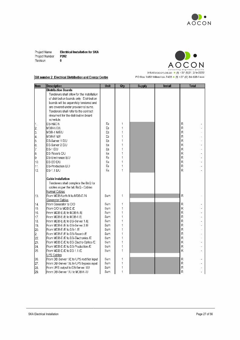
4. Distribution Boards
Distribution Boards shall be produced in accordance with the single line diagrams provided and installed in the positions indicated on drawings. The schedule of Distribution Boards to be supplied as a part of this contract is as follows:
DB Name DB Type Fault Level Main Switch
*DB-H&C N Floor standing, indoor (under stair) 12kA ** 600 A
*MDB-N E/U Floor standing, indoor (in riser, GF) 11 kA ** 250 A
*MDB-1 N/E/U Floor standing, indoor (in riser, 1) 8 kA ** 250 A
MDB-E N/E Floor standing, outdoor (new) 6 kA ** 600 A
DB-Server 1 E/U Wall mount, surface (new) 6 kA ** 100 A
DB-Server 2 E/U Wall mount, surface (new) 6 kA ** 100 A
DB-1 E/U Wall mount, surface (new) 6 kA ** 63 A
DB-Reverb E/U Wall mount, surface (new) 6 kA ** 63 A
DB-Electronics E/U Wall mount, surface (new) 6 kA ** 63 A
DB-EO E/U Wall mount, surface (new) 6 kA ** 63 A
DB-Production E/U Wall mount, surface (new) 6 kA ** 63 A
DB-1.1 E/U Wall mount, surface (new) 6 kA ** 63 A
* = existing ** = estimated 5. Cable Installation
Cables shall be installed in the positions indicated on drawings and installed as specified.

SKA Electrical Installation
Page 21 of 56
The cable schedule for this contract is as follows:
From To Cables in
Parallel
Cable Specification and Size
Earth Wire Specification and
Size
Length
Normal Cables
MDB-North N MDB-E /N 4 300mm² XLPE Cu SC 70mm² BCEW 360 m
Generator Cables
Generator C/O 4 300mm² XLPE Cu SC 70mm² IEW 24 m
C/O MDB-E /E 4 300mm² XLPE Cu SC 70mm² IEW 24 m
MDB-E /E MDB-N /E 1 35mm² PVC SWA PVC Cu 25mm² IEW 90 m
MDB-E /E MDB-1 /E 1 35mm² PVC SWA PVC Cu 25mm² IEW 94 m
MDB-E /E DB-Server 1 /E 1 35mm² PVC SWA PVC Cu 25mm² IEW 100 m
MDB-E /E DB-Server 2 /E 1 35mm² PVC SWA PVC Cu 25mm² IEW 100 m
MDB-E /E DB-1 /E 1 16mm² PVC SWA PVC Cu 10mm² IEW 90 m
MDB-E /E DB-Reverb /E 1 10mm² PVC SWA PVC Cu 6mm² IEW 90 m
MDB-E /E DB-Electronics /E 1 10mm² PVC SWA PVC Cu 6mm² IEW 90 m
MDB-E /E DB-EO /E 1 10mm² PVC SWA PVC Cu 6mm² IEW 90 m
MDB-E /E DB-Production /E 1 10mm² PVC SWA PVC Cu 6mm² IEW 90 m
MDB-E /E DB-1.1 /E 1 10mm² PVC SWA PVC Cu 6mm² IEW 90 m
UPS Cables
DB-Server 1/E UPS rectifier input 1 4G 35mm² HO7 25mm² IEW 12 m
DB-Server 1/E UPS bypass input 1 4G 35mm² HO7 25mm² IEW 12 m
UPS output DB-Server 1/U 1 4G 35mm² HO7 25mm² IEW 12 m
DB-Server 1/U MDB-N /U 1 10mm² PVC SWA PVC Cu 6mm² IEW 60 m
DB-Server 1/U MDB-1 /U 1 10mm² PVC SWA PVC Cu 6mm² IEW 65 m
DB-Server 1/U DB-Server 2 /U 1 10mm² PVC SWA PVC Cu 6mm² IEW 20 m
DB-Server 1/U DB-1 /U 1 10mm² PVC SWA PVC Cu 6mm² IEW 20 m
DB-Server 1/U DB-Reverb /U 1 10mm² PVC SWA PVC Cu 6mm² IEW 20 m
DB-Server 1/U DB-Electronics /U 1 10mm² PVC SWA PVC Cu 6mm² IEW 20 m
DB-Server 1/U DB-EO /U 1 10mm² PVC SWA PVC Cu 6mm² IEW 20 m
DB-Server 1/U DB-Production /U 1 10mm² PVC SWA PVC Cu 6mm² IEW 40 m
DB-Server 1/U DB-1.1 /U 1 10mm² PVC SWA PVC Cu 6mm² IEW 20 m 6. Sleeves
All electrical and Telkom sleeves shall be supplied and installed by the electrical contractor. In addition to the sleeves shown on the electrical drawings, Electrical Contractor to ensure sufficient sleeves/conduits are provided for all power, lighting, security and comms services (internal and external). Sleeves shall be similar or equal to Nextube Kabelflex range of sleeves and installed as per the manufacturers guidelines and SANS 1200.
7. Lighting
The contractor shall supply and install lighting as per the drawings. Lighting shall be controlled by a master on/off switch per floor.

SKA Electrical Installation
Page 22 of 56
The following lighting schedule is applicable to this project:
Luminaire Reference Luminaire Description Proposed Specification (similar or equal in all respects to)
Type A 1200 x 600mm lay-in fluorescent with 2x28W T5 fluorescent lamps
Lighting Innovations Admiral RAD-228-002 + 3m cab + ECG
Type AE 1200 x 600mm lay-in fluorescent with 2x28W T5 fluorescent lamps and emergency battery backup
Lighting Innovations Admiral RAD-228-002 + 3m cab + ECG + 1-hour battery backup at 25% to 1 lamp
Type B 2 x 36W surface mounted LBR fluorescent with 2x36W T8 fluorescent lamps to match existing in all respects aesthetically- to be supplied with ECG ballast
To match in all respects
Type BE 2 x 36W surface mounted LBR fluorescent with 2x36W T8 fluorescent lamps to match existing in all respects aesthetically- to be supplied with ECG ballast and equipped with emergency battery backup
To match in all respects + 1-hour battery backup at 25% to 1 lamp
Type C 2x 36W open channel fluorescent luminaire to be supplied with magnetic wire-wound ballast (not ECG due to EMI interference in key area)
Lighting Innovations Beta SCM-236-000 + ECG
Type C 2x 36W open channel fluorescent luminaire to be supplied with magnetic wire-wound ballast (not ECG due to EMI interference in key area) and emergency battery backup
Lighting Innovations Beta SCM-236-000 + ECG + 1-hour battery backup at 25% to 1 lamp
8. Switched Socket Outlets
Power outlets shall be installed in accordance with the drawing as indicated.
9. Supplies to Fixed Appliances
To be installed as indicated in accordance with legislative and manufacturer requirements. 10. Photoelectric Cells (Photocells)
Photocells shall be of the National type and rated at 16A. Photocells shall be installed in dummy bulkheads to the approval of the architect in the location indicated on the drawing. Photocells shall be wired to the DB by means of a 1.5mm² 4-core surfix cable, contained in a 25mm conduit. All termination provisions shall be on terminal blocks within the DB (provided by the DB manufacturer) and photocells will be wired with an override facility.

SKA Electrical Installation
Page 23 of 56
PART 6
BILLS OF QUANTITIES

SKA Electrical Installation
Page 24 of 56
Preamble to Bills of Quantities 1. There are two Bills of Quantities to be priced. Failure to complete either will result in the nullification of any tender. 2. Any contingency is to be allocated at the discretion of the Engineer and only when done so in writing. 3. This Schedule of Quantities forms part of, and must be read in conjunction with the Specification. The Price
Summary is to reflect the total price carried forward from the Schedule of Quantities, which itself need not be submitted with the tender documents.
4. The tender price must be based on the Schedule of Quantities. Any Tenderer requested to submit his priced Schedule of Quantities shall do so within 48 hours of such request. The format of this submission shall be Microsoft Excel and shall be free of Macro’s, populated with formulae and complete in all respected in order to correlate with the submission as included at tender stage.
5. No alteration, erasure or addition is to be made in the text of the Schedule of Quantities. Should any erasure or addition be made it will not be recognised but the original wording of the Schedule of Quantities will be adhered to.
6. The Sub-Contractor shall be relieved of responsibility of measuring quantities at the tender stage, and the tender sum submitted shall be in respect of the quantities set out in the Bills of Quantities and Specification. Although he will be required to make his assessment of items such as brackets, fixings, etc., from details stated in the Bills and shall include in the item prices for such small installation materials as are required for the complete installation in accordance with the specification.
7. Bills of Quantities form part of and must be read in conjunction with the specification document and drawings which contains the full descriptions of the work to be done and material and equipment to be used and unless otherwise described in the Bills of Quantities, reference should be made to the specification for the full meaning of descriptions of work to be done and materials and equipment to be used in this service.
8. The total tender price in the tender form shall constitute the contract price of the Sub-Contractor. Sub-Contractors are advised to check their item extensions and total additions, as no claim for arithmetical errors will be considered.
9. The onus to ensure accuracy of the tender offering is left to the tenderer. 10. Only major Items have been scheduled but the Tenderer shall nevertheless include for all things he considers
necessary whether specified in detail or not to complete the work to specification. No extra price will be considered for the provision of material or labour which should have been allowed for in order to provide the completed works unless set out in detail and submitted separately by the Tenderer with his tender.
11. All Items are deemed to include supply, delivery, installation and connection where appropriate, unless specifically stated otherwise. The unit rate must include for all things necessary, whether specified in detail or not, including all components, small installation materials, allowance for off-cuts, wastage, etc. erection and fixings to complete the Item to Specification in a satisfactory and workmanlike manner in order to provide a complete and working system.
12. "Material Rate" shall include the supply and delivery of all items of material and equipment (plant) to the site including all incidentals necessary for the completion of each Item, plus the profit but shall exclude VAT which shall be added as a separate item in the Price Summary. The Sub-Contractor shall price the Preliminaries under any or all of three groups, viz,:
a. A fixed amount. b. An amount varied in proportion to the final contract amount as compared to the originally specified contract
amount. c. An amount varied in proportion to the final contract periods as compared to the originally specified contract
period. 13. No alteration, erasure or addition is to be made in the text of the Bills of Quantities. Should any alteration, erasure
or addition be made, it will not be recognised but the original wording of the Bills of Quantities will be adhered to. 14. The quantities in the Schedule are not to be considered as limiting or extending the amount of work to be done and
materials to be supplied. 15. The Sub-Contractor and the Employer or his Agent may agree that the total of any Bill or Bills, including any
variations by way of additions thereto or deductions therefrom, represents a fair and accurate quantification of the items as set out in the Bills and the parties may agree final payment on that basis. In the event of any dispute as to the quantities, then the disputed item or items shall be adjusted where necessary.
16. The Bills of Quantities are provisional and no claim for loss of profits etc. will be accepted due to change in the scope of the works.
17. The Priced Bills of Quantities of the Electrical sub-contractor will be checked and the Engineer reserves the right to call for adjustments to any individual price and to rectify any discrepancy whilst the total tender price, as submitted, remains unaltered.
18. The responsibility for the accuracy of the Quantities written into the Bills remains with the person who prepared the Bills.
19. The quantities in these Bills of Quantities are provisional and not to be used for ordering materials.

SKA Electrical Installation
Page 25 of 56
20. Variations in the scope and extent of the work included in the Bills shall be allowed to meet the Employer’s requirements and shall be measured and costed at rates entered in the Bills, where appropriate, and shall form an addition to or deduction from the total of the Bills. Any items or variation for which rates have not been included in the Bills shall be agreed and priced as non-scheduled items in accordance with the provisions of the contract.
21. Unless stated to the contrary in the Particular Specification, quantities, with the exception of cable, cable joints, trenches, bedding and cover sand, cable slabs, cable and joint markers and pole holes, will not be measured on site in which case the successful Tenderer shall, within 60 days of notification of acceptance of his tender, notify the Engineer in writing of any discrepancies between the drawings, Specification and the quantities of any Item in the Schedule of Quantities, listing each such discrepancy in detail. Where it is agreed by the Engineer that any such claims are valid, the contract price will be adjusted accordingly. No further claim will be entertained except where the Employer changes the requirements of the Contract, in which case such variations will be based on unit prices quoted, where applicable. Escalation costs will, where necessary, be made on the basis of unit rates.
22. The allocation of prices to the three categories listed above must be realistic and the Sub-Contractor may be required to justify the allocation of the prices.
23. All provisional sums shall be expended as directed by the Engineer and any balance remaining shall be deducted from the amount of the contract sum.

SKA Electrical Installation
Page 26 of 56
SKA Electrical Installation
Page 27 of 56

SKA Electrical Installation
Page 28 of 56

SKA Electrical Installation
Page 29 of 56

SKA Electrical Installation
Page 30 of 56

SKA Electrical Installation
Page 31 of 56

SKA Electrical Installation
Page 32 of 56

SKA Electrical Installation
Page 33 of 56

SKA Electrical Installation
Page 34 of 56

SKA Electrical Installation
Page 35 of 56
PART 7
SCHEDULE OF RETURNABLE ITEMS

SKA Electrical Installation
Page 36 of 56
Part A: Schedule of Rates for Variations and Payment Items The following nett prices (excluding VAT) shall serve as a basis for any additions to or omissions from the specified electrical installation, subject to the following:
a. All items in the schedule shall comply with the relevant clauses in the specification. b. Omissions are to be calculated at the scheduled rates less 2½% In the case of repetitive work, such as typical floors,
the 2½% shall be deducted in respect of the basic unit only. c. These rates shall only apply if not covered by a rate in the provisional bills of quantities.
1. Conduit
Supply and installation of conduit including for sets, waste, couplings and drawboxes. "Conduit ends" shall include adaptor/locknuts at one end and conduit box at other (up to 25mm), or adaptor/locknuts at both ends (32-50mm). PVC Conduit In the event of surface fixed conduit, it shall be assumed that PVC conduit saddles are installed at 1000mm intervals.
Size Cast/Built in Surface Fixed Chased (b/work) Chased (conc.) Conduit Ends
20mm R /m R /m R /m R /m R Ea
25mm R /m R /m R /m R /m R Ea
32mm R /m R /m R /m R /m R Ea
40mm R /m R /m R /m R /m R Ea
50mm R /m R /m R /m R /m R Ea
PVC Conduit for Life Critical Services In the event of surface fixed conduit, it shall be assumed that galvanised raised hospital conduit saddles are installed at 500mm intervals.
Size Surface Fixed
20mm R /m
25mm R /m
Galvanised Steel Conduit (Bosal) In the event of surface fixed conduit, it shall be assumed that galvanised conduit saddles (strappers) are installed at 1000mm intervals.
Size Cast/Built in Surface Fixed Chased (b/work) Chased (conc.) Conduit Ends
20mm R /m R /m R /m R /m R Ea
25mm R /m R /m R /m R /m R Ea
32mm R /m R /m R /m R /m R Ea
Black Enamel Conduit In the event of surface fixed conduit, it shall be assumed that galvanised conduit saddles (strappers) are installed at 1000mm intervals.
Size Cast/Built in Surface Fixed Chased (b/work) Chased (conc.) Conduit Ends
20mm R /m R /m R /m R /m R Ea
25mm R /m R /m R /m R /m R Ea
32mm R /m R /m R /m R /m R Ea
Sprague "Conduit ends" shall include flexible conduit adaptors at one end and conduit box at other (up to 25mm), or adaptor/ locknuts at both ends (32-50mm).
Size PVC PVC Ends Metallic Metallic Ends
20mm R /m R /m R /m R /m
25mm R /m R /m R /m R /m
32mm R /m R /m R /m R /m

SKA Electrical Installation
Page 37 of 56
2. Cabling and Wiring Cost is deemed to include terminations in circuit breaker terminal or on wiring accessory as the case may be. Trunking is deemed to be either power skirting, wiring channel, ega tube or any other channel type infrastructure as may be deployed, regardless as to the height of the installation. It shall be noted that joints will only be permitted in DB’s or drawboxes and joints shall be done with insulated ferrules. Single Core Wiring Supply and installation of single core general purpose house wire with high conductivity annealed stranded copper conductors to SANS 1411 Part 1. Insulated with PVC and skin coloured in plain colours to SANS 1411 Part 2. Cable is manufactured to SANS 1507 Part 2. Bare copper earth wire (BCEW) shall comprise of high conductivity plain soft stranded copper conductors to SANS 1411.
Size PVC in Conduit PVC in Trunking BCEW in Conduit BCEW in Trunking
1.5 mm² R /m R /m R /m R /m
2.5 mm² R /m R /m R /m R /m
4 mm² R /m R /m R /m R /m
6 mm² R /m R /m R /m R /m
10 mm² R /m R /m R /m R /m
16 mm² R /m R /m R /m R /m
25 mm² R /m R /m R /m R /m
35 mm² R /m R /m R /m R /m
50 mm² R /m R /m R /m R /m
70 mm² R /m R /m R /m R /m
Multi-core Wiring (Surfix/Norsk Cabling) Supply and installation of multi-core individually insulated copper conductors to SANS 1411 Part 1, PVC insulated to SANS 1411 Part 2, laid up with a bare tinned copper earth wire in contact with a longitudinal aluminium/polyethylene laminate, UV stable PVC sheathed to SANS 1411 Part 2. Surface mounting shall deem fixed by means of easy-holds or similar containment accessories at 1000mm spacing. Terminations shall comprise of a suitably sized compression gland at each end, either of a push-in or conventional lock-nut type. Installation in trunking shall also be deemed to include roof access wiring and wiring in hollow core walls. It shall be clearly and specifically noted that in no instance at all will it be acceptable to embed Surfix/Norsk cabling in plaster. No requests or correspondence to the contrary will be entertained.
Size Cores Surface Mounted In Trunking Termination
1.5 mm² 2 R /m R /m R Ea
1.5 mm² 3 R /m R /m R Ea
1.5 mm² 4 R /m R /m R Ea
2.5 mm² 2 R /m R /m R Ea
2.5 mm² 3 R /m R /m R Ea
2.5 mm² 4 R /m R /m R Ea
4 mm² 2 R /m R /m R Ea
4 mm² 3 R /m R /m R Ea
4 mm² 4 R /m R /m R Ea
6 mm² 2 R /m R /m R Ea
6 mm² 3 R /m R /m R Ea
6 mm² 4 R /m R /m R Ea

SKA Electrical Installation
Page 38 of 56
Multi-core Wiring (Flat Twin and Earth) Supply and installation of multi-core individually insulated copper conductors to SANS 1411 Part 1 laid up with a bare copper earth-continuity-conductor between them, UV stable PVC sheathed to SANS 1411 Part 2. Surface mounting shall deem fixed by means of easy-holds or similar containment accessories at 1000mm spacing. Terminations shall comprise of a suitably sized compression gland at each end, either of a push-in or conventional lock-nut type. Installation in trunking shall also be deemed to include roof access wiring and wiring in hollow core walls. It shall be clearly and specifically noted that in no instance at all will it be acceptable to embed Flat Twin and Earth cabling in plaster. No requests or correspondence to the contrary will be entertained.
Size Cores Surface Mounted In Trunking Termination
1.5 mm² 2 R /m R /m R Ea
1.5 mm² 3 R /m R /m R Ea
2.5 mm² 2 R /m R /m R Ea
2.5 mm² 3 R /m R /m R Ea
4 mm² 2 R /m R /m R Ea
4 mm² 3 R /m R /m R Ea
6 mm² 2 R /m R /m R Ea
10 mm² 2 R /m R /m R Ea
PVC SWA PVC Cu LV Cables Supply and installation of multi-core PVC insulated PVC bedded SWA PVC sheathed 600/1000 V cables with copper conductors and manufactured to SANS 1507-3 per meter run. Terminations are deemed to include lugs, consumables, compression gland, shroud and final connection.
Size Cores In Duct or Trench Surface, Tray or Rack Mtd Termination
1.5 mm² 2 R /m R /m R Ea
1.5 mm² 3 R /m R /m R Ea
1.5 mm² 4 R /m R /m R Ea
2.5 mm² 2 R /m R /m R Ea
2.5 mm² 3 R /m R /m R Ea
2.5 mm² 4 R /m R /m R Ea
4 mm² 2 R /m R /m R Ea
4 mm² 3 R /m R /m R Ea
4 mm² 4 R /m R /m R Ea
6 mm² 2 R /m R /m R Ea
6 mm² 3 R /m R /m R Ea
6 mm² 4 R /m R /m R Ea
10 mm² 3 R /m R /m R Ea
10 mm² 4 R /m R /m R Ea
16 mm² 3 R /m R /m R Ea
25 mm² 4 R /m R /m R Ea
35 mm² 4 R /m R /m R Ea
50 mm² 4 R /m R /m R Ea
70 mm² 4 R /m R /m R Ea
95 mm² 4 R /m R /m R Ea
120 mm² 4 R /m R /m R Ea
150 mm² 4 R /m R /m R Ea
185 mm² 4 R /m R /m R Ea
240 mm² 4 R /m R /m R Ea
300 mm² 4 R /m R /m R Ea

SKA Electrical Installation
Page 39 of 56
PVC SWA PVC Al LV Cables Supply and installation of multi-core PVC insulated PVC bedded SWA PVC sheathed 600/1000 V cables with aluminium conductors and manufactured to SANS 1507-3 per meter run. Terminations are deemed to include lugs, consumables (including insulation tape and Denso paste), compression gland, shroud and final connection. Aluminium lugs shall be costed for.
Size Cores In Duct or Trench Surface, Tray or Rack Mtd Termination
25 mm² 4 R /m R /m R Ea
35 mm² 4 R /m R /m R Ea
50 mm² 4 R /m R /m R Ea
70 mm² 4 R /m R /m R Ea
95 mm² 4 R /m R /m R Ea
120 mm² 4 R /m R /m R Ea
150 mm² 4 R /m R /m R Ea
185 mm² 4 R /m R /m R Ea
240 mm² 4 R /m R /m R Ea
300 mm² 4 R /m R /m R Ea
3. Containment
Supply and installation of cable containment as indicated, including joiner clips/splice kits/couplings as the case may be and earth continuity bond to comprise of 4mm² insulated earth conductor, lugged at each end. The installation shall also include for hold down arrangements on a typical support structure, be it cantilevered or trapeze types. Cable Ladder (Light Duty) Supply and installation of hot dipped galvanised cable ladder with welded construction in standard HDG finish. Cross rung nominal material thickness shall be 1.6mm and rung spacing shall not exceed 375mm. Rung slot size to be maximum 17mm x7mm. Similar or equal to Cabstrut CL55. Support/installation arrangements are not to be included.
Width Straight Lengths Horizontal Bend Vertical Elbow Tee-piece 4-way Crossover
100mm R /m R Ea R Ea R Ea R Ea
150mm R /m R Ea R Ea R Ea R Ea
200mm R /m R Ea R Ea R Ea R Ea
300mm R /m R Ea R Ea R Ea R Ea
400mm R /m R Ea R Ea R Ea R Ea
500mm R /m R Ea R Ea R Ea R Ea
Cable Ladder (Light Duty) Supply and installation of hot dipped galvanised cable ladder with welded construction in standard HDG finish. Cross rung nominal material thickness shall be 1.6mm and rung spacing shall not exceed 375mm. Similar or equal to Cabstrut CL55. Support/installation arrangements are not to be included.
Width Straight Lengths Horizontal Bend Vertical Elbow Tee-piece 4-way Crossover
100mm R /m R Ea R Ea R Ea R Ea
150mm R /m R Ea R Ea R Ea R Ea
200mm R /m R Ea R Ea R Ea R Ea
300mm R /m R Ea R Ea R Ea R Ea
400mm R /m R Ea R Ea R Ea R Ea
500mm R /m R Ea R Ea R Ea R Ea

SKA Electrical Installation
Page 40 of 56
Cable Ladder (Medium Duty) Supply and installation of hot dipped galvanised cable ladder with welded construction in standard HDG finish. Cross rung nominal material thickness shall be 1.6mm and rung spacing shall not exceed 375mm. Similar or equal to Cabstrut CL76. Support/installation arrangements are not to be included.
Width Straight Lengths Horizontal Bend Vertical Elbow Tee-piece 4-way Crossover
100mm R /m R Ea R Ea R Ea R Ea
150mm R /m R Ea R Ea R Ea R Ea
200mm R /m R Ea R Ea R Ea R Ea
300mm R /m R Ea R Ea R Ea R Ea
400mm R /m R Ea R Ea R Ea R Ea
500mm R /m R Ea R Ea R Ea R Ea
600mm R /m R Ea R Ea R Ea R Ea
800mm R /m R Ea R Ea R Ea R Ea
1000mm R /m R Ea R Ea R Ea R Ea
Return Flange Cable Tray (Medium Duty) Supply and installation of hot dipped galvanised cable tray in perforated pressed steel construction in standard HDG finish. Material thicknesses to be 1.0mm for widths from 50mm to 225mm; 1.2mm for 300mm and 1.5mm for all widths upwards to 900mm. Wall height of Medium Duty RFCT shall be 27mm. Similar or equal to Cabstrut RFMD. Support/installation arrangements are not to be included.
Width Straight Lengths Horizontal Bend Vertical Elbow Tee-piece 4-way Crossover
50mm R /m R Ea R Ea R Ea R Ea
75mm R /m R Ea R Ea R Ea R Ea
100mm R /m R Ea R Ea R Ea R Ea
150mm R /m R Ea R Ea R Ea R Ea
225mm R /m R Ea R Ea R Ea R Ea
300mm R /m R Ea R Ea R Ea R Ea
450mm R /m R Ea R Ea R Ea R Ea
Return Flange Cable Tray (Heavy Duty) Supply and installation of hot dipped galvanised cable tray in perforated pressed steel construction in standard HDG finish. Material thicknesses to be 1.0mm for widths from 75mm to 225mm; 1.2mm for 300mm and 1.5mm for all widths upwards to 900mm. Wall height of Medium Duty RFCT shall be 27mm. Similar or equal to Cabstrut RFHD. Support/installation arrangements are not to be included.
Width Straight Lengths Horizontal Bend Vertical Elbow Tee-piece 4-way Crossover
75mm R /m R Ea R Ea R Ea R Ea
100mm R /m R Ea R Ea R Ea R Ea
150mm R /m R Ea R Ea R Ea R Ea
225mm R /m R Ea R Ea R Ea R Ea
300mm R /m R Ea R Ea R Ea R Ea
450mm R /m R Ea R Ea R Ea R Ea
600mm R /m R Ea R Ea R Ea R Ea

SKA Electrical Installation
Page 41 of 56
Perforated Metal Cable Tray (Medium Duty) Supply and installation of hot dipped galvanised cable tray in perforated pressed steel construction in standard HDG finish. Material thicknesses to be 1.0mm for widths from 52mm to 152mm; 1.2mm for 205mm to 305mm. Wall height of medium-duty MCT shall be 38mm. Similar or equal to Cabstrut MCT. Support/installation arrangements are not to be included.
Width Straight Lengths Horizontal Bend Vertical Elbow Tee-piece 4-way Crossover
76mm R /m R Ea R Ea R Ea R Ea
114mm R /m R Ea R Ea R Ea R Ea
152mm R /m R Ea R Ea R Ea R Ea
229mm R /m R Ea R Ea R Ea R Ea
305mm R /m R Ea R Ea R Ea R Ea
Perforated Metal Cable Tray (Heavy Duty) Supply and installation of hot dipped galvanised cable tray in perforated pressed steel construction in standard HDG finish. Material thickness to be 1.6mm for all heavy-duty cable tray. Wall height of Medium Duty MCT shall be 38mm. Similar or equal to Cabstrut HCT. Support/installation arrangements are not to be included.
Width Straight Lengths Horizontal Bend Vertical Elbow Tee-piece 4-way Crossover
76mm R /m R Ea R Ea R Ea R Ea
114mm R /m R Ea R Ea R Ea R Ea
152mm R /m R Ea R Ea R Ea R Ea
229mm R /m R Ea R Ea R Ea R Ea
305mm R /m R Ea R Ea R Ea R Ea
457mm R /m R Ea R Ea R Ea R Ea
610mm R /m R Ea R Ea R Ea R Ea
Welded Wire Mesh Tray (Medium Duty) Supply and installation of hot dipped galvanised cable tray in welded steel wire construction in standard HDG finish. Wire thickness to be 4mm for all WWMD cable tray. Pitch of the welded sections to be 100mm x 50mm. Side walls shall comprise of 2x longitudinal wires at 25mm centres. Similar or equal to Cabstrut WWMD. Support/installation arrangements are not to be included.
Width Straight Lengths Horizontal Bend Vertical Elbow Tee-piece 4-way Crossover
50mm R /m R Ea R Ea R Ea R Ea
100mm R /m R Ea R Ea R Ea R Ea
150mm R /m R Ea R Ea R Ea R Ea
200mm R /m R Ea R Ea R Ea R Ea
300mm R /m R Ea R Ea R Ea R Ea
400mm R /m R Ea R Ea R Ea R Ea
500mm R /m R Ea R Ea R Ea R Ea
600mm R /m R Ea R Ea R Ea R Ea
Welded Wire Mesh Tray (Heavy Duty) Supply and installation of hot dipped galvanised cable tray in welded steel wire construction in standard HDG finish. Wire thickness to be 5mm for all WWHD cable tray. Pitch of the welded sections to be 50mm x 50mm. Side walls shall comprise of 3x longitudinal wires at 25mm centres. Similar or equal to Cabstrut WHMD.

SKA Electrical Installation
Page 42 of 56
Support/installation arrangements are not to be included.
Width Straight Lengths Horizontal Bend Vertical Elbow Tee-piece 4-way Crossover
100mm R /m R Ea R Ea R Ea R Ea
150mm R /m R Ea R Ea R Ea R Ea
200mm R /m R Ea R Ea R Ea R Ea
300mm R /m R Ea R Ea R Ea R Ea
400mm R /m R Ea R Ea R Ea R Ea
500mm R /m R Ea R Ea R Ea R Ea
600mm R /m R Ea R Ea R Ea R Ea
800mm R /m R Ea R Ea R Ea R Ea
1000mm R /m R Ea R Ea R Ea R Ea
Trapeze Hanger Arrangements Supply and installation of threaded rod/Gripple based trapeze arrangements to a maximum height of suspension of 1000mm. Arrangement shall comprise of all fixing and assembly accessories as may be required. Heights exceeding 1000mm shall be qualified in the bills of quantities. Width is deemed internal clearance. Installation cost to include for anchors (where tray is fixed to soffit) and The support component shall be of a minimum 21mm x 41mm trunking with a minimum wall thickness of 2.5mm and all cut ends shall be coated with cold galvanising paint.
Width Support Arrangement Complete
150mm R Ea
250mm R Ea
300mm R Ea
450mm R Ea
650mm R Ea
850mm R Ea
1000mm R Ea
Cantilever Support Arrangements Supply and installation of cantilevered support arms with a minimum wrap around/fixing plate of 135mm. Installation to comprise of 2x suitably sized Shield type anchors. The entire arrangement shall be hot dipped galvanised and be manufactured of 41mm x 41mm square trunking with a minimum wall thickness of 2.5mm. The support component shall be of a minimum 21mm x 41mm trunking and all cut ends shall be coated with cold galvanising paint.
Width Assembly Arrangement Support Arrangement Complete
150mm Single, flat plate R Ea
200mm Single, flat plate R Ea
250mm Single, flat plate R Ea
350mm Single, flat plate R Ea
450mm Single, wrap around R Ea
550mm Single, wrap around R Ea
550mm Half double, wrap around R Ea
550mm Full double, wrap around E Ea
650mm Single, wrap around R Ea
650mm Half double, wrap around R Ea
650mm Full double, wrap around R Ea
850mm Half double, wrap around R Ea
850mm Full double, wrap around R Ea
1050mm Half double, wrap around R Ea
1050mm Full double, wrap around R Ea

SKA Electrical Installation
Page 43 of 56
Steel Wiring Ducting (Steel Lids) The supply and installation of pre-galvanised wiring channels, complete with galvanised steel lids. All cut ends to be treated with cold galvanising paint. All lids shall be installed face up. All wall thicknesses shall be a minimum of 1.5mm for trunking up to 50mm x 50mm and 0.8mm for sizes above. Lids shall be pre galvanised and of a minimum thickness of 0.5mm. Accessories shall be either of the pre-perforated “fold from flat” type or solid arrangement.
Channel Straight Lengths Horizontal Bend Vertical Elbow Tee-piece 4-way Crossover
P1000 R /m R Ea R Ea R Ea R Ea
P2000 R /m R Ea R Ea R Ea R Ea
P4000 R /m R Ea R Ea R Ea R Ea
P8000 R /m R Ea R Ea R Ea R Ea
P9000 R /m R Ea R Ea R Ea R Ea
Steel Wiring Ducting (PVC Lids) The supply and installation of pre-galvanised wiring channels, complete with galvanised steel lids. All cut ends to be treated with cold galvanising paint. All lids shall be installed face up. All wall thicknesses shall be a minimum of 1.5mm for trunking up to 50mm x 50mm and 0.8mm for sizes above. Lids shall have a grey PVC finish. Accessories shall be either of the pre-perforated “fold from flat” type or solid arrangement.
Channel Straight Lengths
P1000 R /m
P2000 R /m
P4000 R /m
P8000 R /m
P9000 R /m
PVC Wiring Ducting (Ega Tube) The supply and installation of PVC extruded wiring channel, with lids. Installation shall be by means of suitable knock in anchors at 500mm intervals. All accessories shall be by the OEM.
Channel Straight Lengths Horizontal Bend Vertical Elbow Tee-piece 4-way Crossover
YT/1 R /m R Ea R Ea R Ea R Ea
YT/2 R /m R Ea R Ea R Ea R Ea
YT/3 R /m R Ea R Ea R Ea R Ea
YT/4 R /m R Ea R Ea R Ea R Ea
YT/5 R /m R Ea R Ea R Ea R Ea
PVC Sleeves The supply and installation of PVC sleeves (Kabelflex Nextube). Trenching measured elsewhere. All accessories shall be by the OEM.
Diameter Straight Lengths 90˚ Slow Bend Coupling End Cap
110mm R /m R Ea R Ea R Ea
160mm R /m R Ea R Ea R Ea

SKA Electrical Installation
Page 44 of 56
Trenching and Backfill Trenching shall deem the opening of ground to a depth as indicated. Backfill shall be as specified and include for the sifting of backfill material in accordance with the specification. Bedding and padding, as well as danger tape and precast concrete pavers shall be included for.
Depth Soft Pickable Soil Semi Rock Hard Rock
600mm R /m R /m R /m
1000mm R /m R /m R /m
4. Dayworks Rates
Labour: The following rates shall be supplied for works not covered by scheduled items:
Staff Normal Time Normal Overtime Sunday/Public Holiday
Electrician R /hr R /hr R /hr
Elconop 1 R /hr R /hr R /hr
Elconop 2 R /hr R /hr R /hr
Elconop 3 R /hr R /hr R /hr
Labourer R /hr R /hr R /hr
Materials: The tenderer shall declare their percentage profit (mark-up) on the nett cost of items:
Staff Percentage Nett Profit Margin
Bulk items > R 1M %
Bulk items > R 30,000 < R 999,999 %
Small items > 5,000 < R 29,999 %
Small items < 4,999 %
Traveling: The tenderer shall declare their travel rates for the vehicle types as listed below:
Vehicle Type Rate/km
Car/LDV (up to 3T) /km
Truck > 3T < 8T /km
Truck > 8T /km

SKA Electrical Installation
Page 45 of 56
Part B: Schedule of Returnables Certificate of Tenderer’s Visit to Site This is to certify that I, Representative of Address of tenderer visited on the Site on (Date) Having previously studied the Contract Documents, I carefully examined the Site. I have made myself familiar with all local conditions likely to influence the work and the cost thereof. I further certify that I am satisfied with the description of the work and explanations given by the Engineer and that I understand perfectly the work to be done, as specified and implied, in the execution of this Subcontract. Signed on behalf of tenderer:
(Who warrants that they are duly authorised thereto in accordance with part 7 of this section) Tenderer Company Stamp:

SKA Electrical Installation
Page 46 of 56
Additional Information About the Tenderer 1. If the tenderer is a Company: List the Directors of the Company, identity number and their appointment date:
Directors Name Identity Number Date of Appointment
Shareholding within Company List the shareholders of the Company
Shareholders Name Identity Number Percentage Shareholding
Company Shareholding: List all companies in which the Company is a shareholder
Company Name Registration Number Percentage Shareholding

SKA Electrical Installation
Page 47 of 56
3. If the tenderer is a Closed Corporation:
List the members of the Closed Corporation, identity number, appointment date and their percentage interest in the CC:
Name of Member Identity Number Appointment Date % Interest
4. If the tenderer is a partnership: List the partners in the Partnership, the date of accession as well as each one’s profit/loss distribution ratio:
Name of Partner Date of Ascension Profit/Loss Distribution Ratio
5. If the tenderer is an individual: List the name and ID number of the individual:
Name of Individual Identity Number
6. Tenderer’s Staff, Labour Force and Financial Statements
Staff Category Total for Company Allocated to Other Projects Proposed Project Allocation
Management
Administration
Artisans
Semi-skilled Labour
Unskilled Labour
Total
Date of latest Financial Statements available Are these audited? Approximate turnover for the past financial year (Rand) Tax clearance certificate included? Signed on behalf of tenderer:
(Who warrants that they are duly authorised thereto in accordance with part 7 of this section)

SKA Electrical Installation
Page 48 of 56
7. Authority for Signatory Signatories for companies, partnerships or closed corporations must establish their authority by attaching a copy of the relevant resolution of their board of Directors, Members or Partners duly signed and dated. Should such a resolution not exist, the following may be completed in lieu thereof: By resolution of the Board of Directors at a meeting on It was resolved and agreed that Mr Whose signature appears below, has been duly authorised to sign all documents in connection with this Tender and Selected Subcontract No Tender for On behalf of (block capitals) Signed on behalf of company In their capacity as Date Signature of signatory Witnesses 1. Signed Name Date 2. Signed Name Date

SKA Electrical Installation
Page 49 of 56
8. Schedule of Recently Completed Projects The Tenderer must insert in the spaces provided below, a list of work completed by him during the past five (5) years, or work at present under construction by his firm. Care shall be taken to include work of a similar nature to that required under this Subcontract.
Project Name Details Consulting Eng. Value of Project Completion Date
Signed on behalf of tenderer:
(Who warrants that they are duly authorised thereto in accordance with part 7 of this section)

SKA Electrical Installation
Page 50 of 56
9. Schedule of Sub-contractors The Tenderer shall list below the Subcontractors whom he intends to appoint for the various specialised items of work on this Subcontract. Alternatives may be mentioned. If the Tenderer intends to carry out specialised work himself he shall state this. The acceptance of the Tender shall not be construed as approval of all or any of the listed Subcontractors. Should any or all of the Subcontractors not be approved subsequent to acceptance of Tender, this shall in no way invalidate this tender and the tendered unit rates for the various items of work shall remain final and binding even in the event of a subcontractor not listed below, being approved by the Engineer.
Portion of Specialised Works Name of Proposed Sub-contractor
Signed on behalf of tenderer:
(Who warrants that they are duly authorised thereto in accordance with part 7 of this section)

SKA Electrical Installation
Page 51 of 56
10. Alternative Tenders The Tenderer may offer alternatives in accordance with the scope where permitted in the tender documents or requested in the bills of quantities. The submission of an alternative offering will not exonerate the tenderer from complying with the base specification. Alternatives shall be submitted as separate bills of quantities, complete with a separate form of tender and marked so as to reference this:
Alternative Detail
Signed on behalf of tenderer:
(Who warrants that they are duly authorised thereto in accordance with part 7 of this section)

SKA Electrical Installation
Page 52 of 56
11. Schedule of Equipment Offered All Tenderers must complete the following schedules and submit these with their Tenders. The schedules will be scrutinised by the Engineer. Should any material offered not comply with the requirements of the Specification, the Subcontractor will be required to supply material in accordance with the requirements of the Specification at no additional cost. Non-completion or partial completion of the schedules may lead to Tender disqualification. Where equipment is clearly not applicable to the project, comment N/A.
Equipment Recommended Manufacturer Proposed Manufacturer
MV Transformer N/A
MV Switchgear N/A
LV Distribution Boards To be tendered
Metering Included in DB
MV Cables N/A
LV Cables Aberdare
MV Terminations N/A
LV Terminations CCG
Cable Ladder O-line/Cabstrut
Cable Mesh Tray O-line/Cabstrut
Conduit Crabtree
Surfix/Twin & Earth Aberdare
Unistrut O-line/Cabstrut
Special floor trunking N/A
Power skirting OBO and accessories
Light Switches (General) Crabtree
Light Switches (Special) Legrand
Switched Socket Outlets (skirting) Legrand
Switched Socket Outlets (General) Crabtree
Switched Socket Outlets (Special) Legrand
Welding plugs Gewiss
Isolators weatherproof Rotary type Gewiss
Partition Boxes Crabtree
Circuit Breakers ABB
Fused Cartridges & bases ABB
Contactors & Accessories ABB
Electronic control timers ABB
Auxiliary Relays ABB
Indicating lamps (LED) ABB/Allbro
Terminals Allbro
Control Transformers N/A
Push buttons & selector switches ABB/Allbro
Control & Selector switches ABB/Allbro
Wire & Cable ferrules Hellerman Tyton
Cable number tags Hellerman Tyton
Lamps Osram
Photocell National
Time Switches ABB

SKA Electrical Installation
Page 53 of 56
Dimmers Shuttle
PART 8
SCHEDULE OF DRAWINGS

SKA Electrical Installation
Page 54 of 56
Drawings The following drawings form an integral part of this specification:
Drawing Number Drawing Name
P202-C-001 Ground Floor Containment Layout
P202-E-001 Ground Floor Electronic Services Layout
P202-P-001 Ground Floor Power Layout
P202-L-001 Ground Floor Lighting Layout
P202-C-002 First Floor Containment Layout
P202-E-002 First Floor Electronic Services Layout
P202-P-002 First Floor Power Layout
P202-L-002 First Floor Lighting Layout

DB-REVERB
DB-1
DB-SERVER
DB-PROD
MDB
DB-EO
DB-ELECT
MDB-E C/O GEN
LEGEND:ELECTRICAL DISTRIBUTION BOARD
300mm WWMD CABLE LADDER
2 LID 2 COMPARTMENT POWERSKIRTING
NEW 225mm RFMD CABLE TRAY WITH 2x DIVIDERSTRIPS
EXISTING 225mm RFMD CABLE TRAY WITH 2xDIVIDER STRIPS
POWER POLE
GROUND FLOORCONTAINMENT LAYOUT
DRAWING DESCRIPTION
CLIENT
PROJECT
DRAWING NOSCALE (SIZE)
NEW OFFICES FOR SKABLACK RIVER PARK NORTH
SKA
REVISIONP202-C-001
DRAWN BYDESIGNED BYVP
PURPOSE2018.03.14
CHECKED BYGC
DATE OF FIRST ISSUEGC
1:100 (@A1)
PURPOSE:
COSTING
APPROVAL
Copyright ©The information contained in this document represents the intellectualproperty of AOCon Consulting Engineers (Pty) Ltd and is affordedprotection by the Copyright Act, Act 78 of 1978 and the IntellectualProperty Laws Amendment Act of 2013. The content of thisdocument is vested in AOCon Consulting Engineers (Pty) Ltd and thisinformation is issued for the purpose only for which it is intended. Itmay not be reproduced in whole or in part or used for any otherpurposes except with the written consent of AOCon ConsultingEngineers (Pty) Ltd, and only then on the condition that this notice isincluded in any such reproduction thereof. No information as to thecontents or subject matter of this document, or any part thereofarising directly or indirectly therefrom shall be given orally or in writingor communicated in any manner whatsoever to any third party beingan individual, firm or company or any employee thereof without theprior written consent of AOCon Consulting Engineers (Pty) Ltd.
TENDER
INFORMATION
CONSTRUCTION
DISCUSSION
REV DATE REVISIONS BY
DRAWING REFERENCE:
ARCHITECT:
ELECTRICAL ENGINEER:
0 TENDER
c o n s u l t i n g e n g i n e e r s (p t y) l t dr e g . n . o . 2 0 1 4 / 2 6 7 2 0 5 / 0 7
A O C O NP O B o x 1 6 8 0 M i l n e r t o n 7 4 3 5
E m a i l i n f o @ a o c o n . c o . z aT e l + 2 7 ( 0 ) 2 1 2 7 6 2 2 2 2
NOTES:
0-0 GF
0 2018.03.14 GCISSUED FOR TENDER

MDB-1
LEGEND:ELECTRICAL DISTRIBUTION BOARD
300mm WWMD CABLE LADDER
2 LID 2 COMPARTMENT POWERSKIRTING
NEW 225mm RFMD CABLE TRAY WITH 2x DIVIDERSTRIPS
EXISTING 225mm RFMD CABLE TRAY WITH 2xDIVIDER STRIPS
POWER POLE
FIRST FLOORCONTAINMENT LAYOUT
DRAWING DESCRIPTION
CLIENT
PROJECT
DRAWING NOSCALE (SIZE)
NEW OFFICES FOR SKABLACK RIVER PARK NORTH
SKA
REVISIONP202-C-002
DRAWN BYDESIGNED BYVP
PURPOSE2018.03.14
CHECKED BYGC
DATE OF FIRST ISSUEGC
1:100 (@A1)
PURPOSE:
COSTING
APPROVAL
Copyright ©The information contained in this document represents the intellectualproperty of AOCon Consulting Engineers (Pty) Ltd and is affordedprotection by the Copyright Act, Act 78 of 1978 and the IntellectualProperty Laws Amendment Act of 2013. The content of thisdocument is vested in AOCon Consulting Engineers (Pty) Ltd and thisinformation is issued for the purpose only for which it is intended. Itmay not be reproduced in whole or in part or used for any otherpurposes except with the written consent of AOCon ConsultingEngineers (Pty) Ltd, and only then on the condition that this notice isincluded in any such reproduction thereof. No information as to thecontents or subject matter of this document, or any part thereofarising directly or indirectly therefrom shall be given orally or in writingor communicated in any manner whatsoever to any third party beingan individual, firm or company or any employee thereof without theprior written consent of AOCon Consulting Engineers (Pty) Ltd.
TENDER
INFORMATION
CONSTRUCTION
DISCUSSION
REV DATE REVISIONS BY
DRAWING REFERENCE:
ARCHITECT:
ELECTRICAL ENGINEER:
0 TENDER
c o n s u l t i n g e n g i n e e r s (p t y) l t dr e g . n . o . 2 0 1 4 / 2 6 7 2 0 5 / 0 7
A O C O NP O B o x 1 6 8 0 M i l n e r t o n 7 4 3 5
E m a i l i n f o @ a o c o n . c o . z aT e l + 2 7 ( 0 ) 2 1 2 7 6 2 2 2 2
NOTES:
1-0 FF
0 2018.03.14 GCISSUED FOR TENDER

BRGBPB
TO OVERHEADTRAY
LEGEND:DATA POINT
FIRST FLOORELECTRONIC SERVICES LAYOUT
DRAWING DESCRIPTION
CLIENT
PROJECT
DRAWING NOSCALE (SIZE)
NEW OFFICES FOR SKABLACK RIVER PARK NORTH
SKA
REVISIONP202-E-002
DRAWN BYDESIGNED BYVP
PURPOSE2018.03.14
CHECKED BYGC
DATE OF FIRST ISSUEGC
1:100 (@A1)
PURPOSE:
COSTING
APPROVAL
Copyright ©The information contained in this document represents the intellectualproperty of AOCon Consulting Engineers (Pty) Ltd and is affordedprotection by the Copyright Act, Act 78 of 1978 and the IntellectualProperty Laws Amendment Act of 2013. The content of thisdocument is vested in AOCon Consulting Engineers (Pty) Ltd and thisinformation is issued for the purpose only for which it is intended. Itmay not be reproduced in whole or in part or used for any otherpurposes except with the written consent of AOCon ConsultingEngineers (Pty) Ltd, and only then on the condition that this notice isincluded in any such reproduction thereof. No information as to thecontents or subject matter of this document, or any part thereofarising directly or indirectly therefrom shall be given orally or in writingor communicated in any manner whatsoever to any third party beingan individual, firm or company or any employee thereof without theprior written consent of AOCon Consulting Engineers (Pty) Ltd.
TENDER
INFORMATION
CONSTRUCTION
DISCUSSION
REV DATE REVISIONS BY
DRAWING REFERENCE:
ARCHITECT:
ELECTRICAL ENGINEER:
0 TENDER
c o n s u l t i n g e n g i n e e r s (p t y) l t dr e g . n . o . 2 0 1 4 / 2 6 7 2 0 5 / 0 7
A O C O NP O B o x 1 6 8 0 M i l n e r t o n 7 4 3 5
E m a i l i n f o @ a o c o n . c o . z aT e l + 2 7 ( 0 ) 2 1 2 7 6 2 2 2 2
NOTES:
1-0 FF
0 2018.03.14 GCISSUED FOR TENDER
TELEPHONE POINT
2 LID 2 COMPARTMENT POWERSKIRTING
BIOMETRIC READER
DOOR RELEASE PUSH BUTTON
B
PB
MAGLOCK
GREEN BREAK GLASS UNIT
RED BREAK GLASS UNIT
GB
R

A
A
A A
A
A
A A
A A
A
A
A
A
A
A
A
A
A
A
A
A
A
A
A
A
A
A
A
A
A
A
A
A
A
A
A
A
A
A
A
A
A
AAA
AAA
AAA
A
A
A
A
A
A
A
A
A A
A
A
A
A
A
A
A
A
A
A
A
A
A
A
A
A
A
A
A
A
A
A
A
A
A
A
A
A
A
A
A A
A
A
A
A
A
A
A
A AA
A AA
A AA
A AA
A AA
A
A
A
A
CE C C C C C CE C C C C C C CE
CC
CC
CE
CCCCCCCCC
CCCCCCC
CCCCCCC
CC
C
C CE CE C C
C CCC
CC
TO LATERDETAIL
EXISTING LIGHTINGTO REMAIN
EXISTING LIGHTING TO REMAIN &MODIFIED TO SUIT NEW LAYOUT
A A
A
B B BE
B
GROUND FLOORLIGHTING LAYOUT
DRAWING DESCRIPTION
CLIENT
PROJECT
DRAWING NOSCALE (SIZE)
NEW OFFICES FOR SKABLACK RIVER PARK NORTH
SKA
REVISIONP202-L-001
DRAWN BYDESIGNED BYVP
PURPOSE2018.03.14
CHECKED BYGC
DATE OF FIRST ISSUEGC
1:100 (@A1)
PURPOSE:
COSTING
APPROVAL
Copyright ©The information contained in this document represents the intellectualproperty of AOCon Consulting Engineers (Pty) Ltd and is affordedprotection by the Copyright Act, Act 78 of 1978 and the IntellectualProperty Laws Amendment Act of 2013. The content of thisdocument is vested in AOCon Consulting Engineers (Pty) Ltd and thisinformation is issued for the purpose only for which it is intended. Itmay not be reproduced in whole or in part or used for any otherpurposes except with the written consent of AOCon ConsultingEngineers (Pty) Ltd, and only then on the condition that this notice isincluded in any such reproduction thereof. No information as to thecontents or subject matter of this document, or any part thereofarising directly or indirectly therefrom shall be given orally or in writingor communicated in any manner whatsoever to any third party beingan individual, firm or company or any employee thereof without theprior written consent of AOCon Consulting Engineers (Pty) Ltd.
TENDER
INFORMATION
CONSTRUCTION
DISCUSSION
REV DATE REVISIONS BY
DRAWING REFERENCE:
LEGEND:
ARCHITECT:
TYPE A LUMINAIRE
ELECTRICAL ENGINEER:
0 TENDER
c o n s u l t i n g e n g i n e e r s (p t y) l t dr e g . n . o . 2 0 1 4 / 2 6 7 2 0 5 / 0 7
A O C O NP O B o x 1 6 8 0 M i l n e r t o n 7 4 3 5
E m a i l i n f o @ a o c o n . c o . z aT e l + 2 7 ( 0 ) 2 1 2 7 6 2 2 2 2
TYPE A LUMINAIRE WITH BATTERY BACKUP
1W 1L LIGHT SWITCH
NOTES:
0-7 GF
ELECTRICAL DISTRIBUTION BOARD
0 2018.03.14 GCISSUED FOR TENDER
TYPE B LUMINAIRE
TYPE B LUMINAIRE WITH BATTERY BACKUP
TYPE C LUMINAIRE
TYPE C LUMINAIRE WITH BATTERY BACKUP
A
AE
B
C
BE
CE
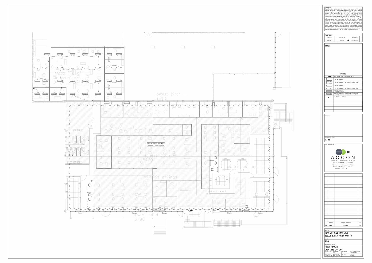
EXISTING LIGHTING TO REMAIN &MODIFIED TO SUIT NEW LAYOUT
CCE
CCE
CCE
CCECCC
CEC
CEC
CEC
CCC
CCC
CCCCEC
C
C
C
C
MDB-1
FIRST FLOORLIGHTING LAYOUT
DRAWING DESCRIPTION
CLIENT
PROJECT
DRAWING NOSCALE (SIZE)
NEW OFFICES FOR SKABLACK RIVER PARK NORTH
SKA
REVISIONP202-L-002
DRAWN BYDESIGNED BYVP
PURPOSE2018.03.14
CHECKED BYGC
DATE OF FIRST ISSUEGC
1:100 (@A1)
PURPOSE:
COSTING
APPROVAL
Copyright ©The information contained in this document represents the intellectualproperty of AOCon Consulting Engineers (Pty) Ltd and is affordedprotection by the Copyright Act, Act 78 of 1978 and the IntellectualProperty Laws Amendment Act of 2013. The content of thisdocument is vested in AOCon Consulting Engineers (Pty) Ltd and thisinformation is issued for the purpose only for which it is intended. Itmay not be reproduced in whole or in part or used for any otherpurposes except with the written consent of AOCon ConsultingEngineers (Pty) Ltd, and only then on the condition that this notice isincluded in any such reproduction thereof. No information as to thecontents or subject matter of this document, or any part thereofarising directly or indirectly therefrom shall be given orally or in writingor communicated in any manner whatsoever to any third party beingan individual, firm or company or any employee thereof without theprior written consent of AOCon Consulting Engineers (Pty) Ltd.
TENDER
INFORMATION
CONSTRUCTION
DISCUSSION
REV DATE REVISIONS BY
DRAWING REFERENCE:
LEGEND:
ARCHITECT:
TYPE A LUMINAIRE
ELECTRICAL ENGINEER:
0 TENDER
c o n s u l t i n g e n g i n e e r s (p t y) l t dr e g . n . o . 2 0 1 4 / 2 6 7 2 0 5 / 0 7
A O C O NP O B o x 1 6 8 0 M i l n e r t o n 7 4 3 5
E m a i l i n f o @ a o c o n . c o . z aT e l + 2 7 ( 0 ) 2 1 2 7 6 2 2 2 2
TYPE A LUMINAIRE WITH BATTERY BACKUP
1W 1L LIGHT SWITCH
NOTES:
1-7 FF
ELECTRICAL DISTRIBUTION BOARD
0 2018.03.14 GCISSUED FOR TENDER
TYPE B LUMINAIRE
TYPE B LUMINAIRE WITH BATTERY BACKUP
TYPE C LUMINAIRE
TYPE C LUMINAIRE WITH BATTERY BACKUP
A
AE
B
C
BE
CE

DB-REVERB
DB-1
DB-SERVER
DB-PROD
MDB
DB-EO
DB-ELECT
MDB-E C/O GEN
P1ELECT
P2ELECT
P3ELECT
P4ELECT
P5ELECT
P6ELECT
P7ELECT
P8ELECT
P9ELECT
POW
ERSK
IRTI
NG @
1300
mm A
FFL
POWERSKIRTING @ 1300mm AFFL POWERSKIRTING @ 300mm AFFL
P1EO
POWERSKIRTING @ 1300mm AFFL
P2EO
P3EO
32AWPPP1EO
32AWP
PP2EO
32AWP
PP3EO
+300AFFL
PP5EO
32AWP
PP4EO
+300AFFL
+300AFFL
+300AFFL
+300AFFL
+300AFFL
+300AFFL
+300AFFL
+300AFFL
+300AFFL
32AWP
32AWP
32A
+300 AFFL+1500 AFFL
D21MDB
P19MDB
D22MDB
P18MDB
D20MDB
P17MDB
P16MDB
D19MDB
D18MDB
P15MDB
TO LATER DETAIL
TO LATER DETAIL
TO LATER DETAIL
D17MDB
P14MDB
+300AFFL
P71
D91
D81D4
1
P91 D5
1
P81
P31
D31
P1REV
P2REV
P3REV
D21
P21
D11
+300AFFL+300AFFL
P11
P41
D61
P51
D71
P61
TO LATER DETAIL
D12MDB
P9MDB
D11MDB
P6MDB
P7MDB
P8MDB
D9MDB
P4MDB
D10MDB
P5MDB
+300
AFF
L
+150
0 AFF
L
+1500 AFFL
+300AFFL
D1MDB
P1MDB
D2MDB
P2MDB
P3MDB
D3MDB
D14MDB
P10MDB
D13MDB
P11MDB
+300AFFL
+300AFFL
+300AFFL
+300AFFL
D15MDB
P12MDB
D16MDB
P13MDB
P21MDB
+300AFFL
+300AFFL
+300AFFL
+300AFFL
D8MDB
P24MDB
D7MDB
P28MDB
D5MDB
P27MDB
D6MDB
P26MDB
P22MDB
P28MDB
D4MDB
P23MDB
P25MDB
LEGEND:
16A SWITCHED SOCKET OUTLET (DOUBLE)
ELECTRICAL DISTRIBUTION BOARD
16A SWITCHED SOCKET OUTLET (SINGLE)
32A SWITCHED SOCKET OUTLET
32A ISOLATOR
GROUND FLOORPOWER LAYOUT
DRAWING DESCRIPTION
CLIENT
PROJECT
DRAWING NOSCALE (SIZE)
NEW OFFICES FOR SKABLACK RIVER PARK NORTH
SKA
REVISIONP202-P-001
DRAWN BYDESIGNED BYVP
PURPOSE2018.03.14
CHECKED BYGC
DATE OF FIRST ISSUEGC
1:100 (@A1)
PURPOSE:
COSTING
APPROVAL
Copyright ©The information contained in this document represents the intellectualproperty of AOCon Consulting Engineers (Pty) Ltd and is affordedprotection by the Copyright Act, Act 78 of 1978 and the IntellectualProperty Laws Amendment Act of 2013. The content of thisdocument is vested in AOCon Consulting Engineers (Pty) Ltd and thisinformation is issued for the purpose only for which it is intended. Itmay not be reproduced in whole or in part or used for any otherpurposes except with the written consent of AOCon ConsultingEngineers (Pty) Ltd, and only then on the condition that this notice isincluded in any such reproduction thereof. No information as to thecontents or subject matter of this document, or any part thereofarising directly or indirectly therefrom shall be given orally or in writingor communicated in any manner whatsoever to any third party beingan individual, firm or company or any employee thereof without theprior written consent of AOCon Consulting Engineers (Pty) Ltd.
TENDER
INFORMATION
CONSTRUCTION
DISCUSSION
REV DATE REVISIONS BY
DRAWING REFERENCE:
ARCHITECT:
ELECTRICAL ENGINEER:
0 TENDER
c o n s u l t i n g e n g i n e e r s (p t y) l t dr e g . n . o . 2 0 1 4 / 2 6 7 2 0 5 / 0 7
A O C O NP O B o x 1 6 8 0 M i l n e r t o n 7 4 3 5
E m a i l i n f o @ a o c o n . c o . z aT e l + 2 7 ( 0 ) 2 1 2 7 6 2 2 2 2
NOTES:
0-0 GF
0 2018.03.14 GCISSUED FOR TENDER
16A SWITCHED SOCKET OUTLET (SINGLE)
2 LID 2 COMPARTMENT POWERSKIRTING

MDB-1
D21.1
P21.1
+300 AFFL
+1500 AFFL
+300AFFL
TO LATER DETAIL
DB-1.1
D11.1
P11.1
D31.1
P31.1
P41.1
D41.1
D51.1
P51.1
P61.1
D61.1
+300AFFL
+300AFFL
+300AFFL
+300AFFL +300
AFFL
D141
P141
D151
P151
+300AFFL
+300AFFL
P191
D161
P161
+300AFFL
+300AFFL
+300AFFL
+300AFFL
+300 AFFL
+1500 AFFL
+300AFFL
+300AFFL
+300AFFL
+300AFFL
+300AFFL
P131
D131 P12
1
D121
P111
D111
D91
P91
D81
P81
D101
P101
P71
D71
P11
D11
D21
P21
D31
P31
D41
P41
+300AFFL
P51
D51
P61
D61
P221
P211
P201
D171
P171
D181
P181
P181
D181
LEGEND:
16A SWITCHED SOCKET OUTLET (DOUBLE)
ELECTRICAL DISTRIBUTION BOARD
16A SWITCHED SOCKET OUTLET (SINGLE)
32A SWITCHED SOCKET OUTLET
32A ISOLATOR
FIRST FLOORPOWER LAYOUT
DRAWING DESCRIPTION
CLIENT
PROJECT
DRAWING NOSCALE (SIZE)
NEW OFFICES FOR SKABLACK RIVER PARK NORTH
SKA
REVISIONP202-P-002
DRAWN BYDESIGNED BYVP
PURPOSE2018.03.14
CHECKED BYGC
DATE OF FIRST ISSUEGC
1:100 (@A1)
PURPOSE:
COSTING
APPROVAL
Copyright ©The information contained in this document represents the intellectualproperty of AOCon Consulting Engineers (Pty) Ltd and is affordedprotection by the Copyright Act, Act 78 of 1978 and the IntellectualProperty Laws Amendment Act of 2013. The content of thisdocument is vested in AOCon Consulting Engineers (Pty) Ltd and thisinformation is issued for the purpose only for which it is intended. Itmay not be reproduced in whole or in part or used for any otherpurposes except with the written consent of AOCon ConsultingEngineers (Pty) Ltd, and only then on the condition that this notice isincluded in any such reproduction thereof. No information as to thecontents or subject matter of this document, or any part thereofarising directly or indirectly therefrom shall be given orally or in writingor communicated in any manner whatsoever to any third party beingan individual, firm or company or any employee thereof without theprior written consent of AOCon Consulting Engineers (Pty) Ltd.
TENDER
INFORMATION
CONSTRUCTION
DISCUSSION
REV DATE REVISIONS BY
DRAWING REFERENCE:
ARCHITECT:
ELECTRICAL ENGINEER:
0 TENDER
c o n s u l t i n g e n g i n e e r s (p t y) l t dr e g . n . o . 2 0 1 4 / 2 6 7 2 0 5 / 0 7
A O C O NP O B o x 1 6 8 0 M i l n e r t o n 7 4 3 5
E m a i l i n f o @ a o c o n . c o . z aT e l + 2 7 ( 0 ) 2 1 2 7 6 2 2 2 2
NOTES:
1-0 FF
0 2018.03.14 GCISSUED FOR TENDER
16A SWITCHED SOCKET OUTLET (SINGLE)
2 LID 2 COMPARTMENT POWERSKIRTING

TO LATER DETAIL
TO LATER DETAIL
LEGEND:DATA POINT
GROUND FLOORVOICE & DATA LAYOUT
DRAWING DESCRIPTION
CLIENT
PROJECT
DRAWING NOSCALE (SIZE)
NEW OFFICES FOR SKABLACK RIVER PARK NORTH
SKA
REVISIONP202-VD-001
DRAWN BYDESIGNED BYVP
PURPOSE2018.03.14
CHECKED BYGC
DATE OF FIRST ISSUEGC
1:100 (@A1)
PURPOSE:
COSTING
APPROVAL
Copyright ©The information contained in this document represents the intellectualproperty of AOCon Consulting Engineers (Pty) Ltd and is affordedprotection by the Copyright Act, Act 78 of 1978 and the IntellectualProperty Laws Amendment Act of 2013. The content of thisdocument is vested in AOCon Consulting Engineers (Pty) Ltd and thisinformation is issued for the purpose only for which it is intended. Itmay not be reproduced in whole or in part or used for any otherpurposes except with the written consent of AOCon ConsultingEngineers (Pty) Ltd, and only then on the condition that this notice isincluded in any such reproduction thereof. No information as to thecontents or subject matter of this document, or any part thereofarising directly or indirectly therefrom shall be given orally or in writingor communicated in any manner whatsoever to any third party beingan individual, firm or company or any employee thereof without theprior written consent of AOCon Consulting Engineers (Pty) Ltd.
TENDER
INFORMATION
CONSTRUCTION
DISCUSSION
REV DATE REVISIONS BY
DRAWING REFERENCE:
ARCHITECT:
ELECTRICAL ENGINEER:
0 TENDER
c o n s u l t i n g e n g i n e e r s (p t y) l t dr e g . n . o . 2 0 1 4 / 2 6 7 2 0 5 / 0 7
A O C O NP O B o x 1 6 8 0 M i l n e r t o n 7 4 3 5
E m a i l i n f o @ a o c o n . c o . z aT e l + 2 7 ( 0 ) 2 1 2 7 6 2 2 2 2
NOTES:
0-0 GF
0 2018.03.14 GCISSUED FOR TENDER
TELEPHONE POINT
2 LID 2 COMPARTMENT POWERSKIRTING

SKA Electrical Installation
Page 55 of 56
PART 9
PROJECT PROGRAMME

SKA Electrical Installation
Page 56 of 56
Project Programme To be provided by the Principal Contractor.