proposed radiological effluent tech specs reflecting mods
TRANSCRIPT

!
.4a,
d
.
PROPOSED
RADIOLOGICAL EFFLUENT TECHNICAL SPECIFICATIONS
POINT BEACH NUCLEAR PLANT
|'
Septerber 30, 1983
,
!
:
|!
hggo gg{20 PDR! Pi,
l
|
}

.
'2) Logic Channel
A logic channel is a group of relay contact matrices which
operate in response to the analog channels signals to generate a
protective action signal.
f. Instrumentation Surveillance
1) Channel Check
Channel check is a qualitative determination of acceptable
operability by observation of channel behavior during operation.
IWhere other channels are provided, this determination shall;
f
include comparison of the channel indication with indications
from other independent instrumentation channels measuring the
same parameter.
2) Channel Functional Test
A channel functional test consists of injecting a simulated
signal into the channel to verify that it is operable, including
alarm and/or trip initiating action.
3) Channel Calibration
Channel calibration consists of the adjustment of channel output
such that it responds, with acceptable range and accuracy, to
known values of the parameter which the channel measures.
Calibration shall encompass the entire channel, including
equipment action, alarm, or trip, and shall be deemed to include
the channel functional test.
4) Source Check
i A source check is an assessment of channel response when the
| channel detector is exposed to a source of increased radiation.
15.1-3
l
i
I
ll
i

- .
4
s
h~
g. Shutdown
1) Hot Shutdown
The reactor is in the hot shutdown condition when the reactor is
suberitical, by an amount greater than or equal to the margin
as specified in Technical Specification 15.3.10 and T is atavg
or greater than 540*F.
!
.
|
15.1-3a
i
!_ - . - _ . . . - _ . . . _ _ . __ _ . _ - _ _ . _ _ _ . - _ _ _ _ . - _ _ . _ _ - _ _ _ _ _ _ . _ . - _ , _ . _ - . . . --

_-.
.
'p. Dose Equivalent I-131
Dose Equivalent I-131 shall be that concentration of I-131 (microcuries/
gram) which alone would produce the same thyroid dose as the quantity,
and isotopic mixture of I-131, I-132, I-133, I-134, and I-135 actually
present. The thyroid dose conversion factors used for this calculation
shall be those listed in Table III of TID-14844, " Calculation of
Distance Factors for Power and Test Reactor Sites."
q. E - Average Disintegration Energy
E shall be the average (weighted in proportion to the concentration of
each radionuclide in the reactor coolant at the time of sampling) of -
the sum of the average beta and gamma energies per disintegration (in
MeV) for isotopes, other than iodines, with half lives greater than 15
minutes, making up at least 95% of the total noniodine activity in the
ecolant.
J
r. Radioactive Waste Handling
1) Process Control Program (PCP)
The Process Control Program contains the current formulas,
sampling methods, analyses, tests, and determinations to be made
to ensure that the processing and packaging of solid radioactive
waste will be accomplished in such a way as to assure compliance
with 10 CFR 20, 10 CFR 71, and ell other Federal and State
regul:tions governing the disposal of the radioactive waste.
2) Solidification
The conversion of wet wastes into a form that meets shipping
burial ground requirements.
15.1-6
_- __ _ _ _ _ _ _ _ _ _ . _ _ . _ __ ..

e
4
s. Offsite Dose Calculation Manual (ODCM)
The Offsite Dose Calculation Manual contains the methodology for the
determination of gaseous and liquid effluent monitoring trip setpoints,
the methodology for determining compliance with release objectives,
and the methodology used in the calculation of offsite doses due to
radioactive gaseous and liquid effluents.
t. Lower Level of Detection (LLD)
The LLD is defined, for purposes of these specifications, as the
smallest concentration of radioactive material in a sample that will ,
yield a net count, above system background, that will be detected with
95% probability with only 5% probability of falsely concluding that a
blank observation represents a "real" signal. For a particular measurement r
Isystem, which may include radiochemical separation: *
.66SbLLD = E x V x 2.22 x 10" x Y x exp (-Aat)
Where:
LLD = the a priori lower limit of detection as defined above,
in microcuries per unit volume,
Sb = the standard deviation of the background counting rate or
of the counting rate of a blank sample as appropriate in;
counts per minute,
E = the counting efficiency in counts per disintegratzen,
V = the sample size in units of volume,
15.1-7
I
. - - , ,

~
s
o i2.22 x 10s = the number of disintegrations per minute per i
microcurie,,
Y = the fractional radiochemical yield, when applicable,
A = the radioactive decay constant for the particular i
radionuclide, and j:
At = the elapsed time between the midpoint of sample collection.
,
!
and time of counting for plant effluents. I
Typical values of E, V, Y, and at will be used in the calculation.
<
It should be recognized that the LLD is defined as an a priori (before ja
the fact) limit representinF the capability of a measurement system i
,
and not as an a posteriori (after the fact) limit for a particular
measurement. ;
.
|
|
LI|
||
\
15.1-8
|
. .. - .__ ._.. ..- . .- -- -- . - .-. - - _ - - - - _
F
,
'15.3.9 Radioactive Effluent Releases
Applicability
Applies to the controlled releases of radioactive gases or liquids from the
plant (s) on a site basis. The provisions of Specification 15.3.0 are not
applicable to these specifications.
Chiective
The limits and conditionn for the controlled release of radioactive
materials in liquid and gaseous effluents to the environs ensure that all
releases are as low as is reasonably achievable in conformance with
10 CFR Parts 50.34a and 50.36; and will ensure that these releases result
in concentrations of radioactive materials in liquid and gaseous effluents
released to unrestricted areas that are within the limits specified in
10 CFR Part 20.
Specifications
A. Radioactive Effluent Monitoring Instrumentation
1) The radioactive effluent monitoring instrumentation channels
listed in Table 15.3.9-1 shall be operable and their trip
setpoints shall be determined utilizing the methodology given in
the ODCM.
2) With less than the minimum number of radioactive effluent
monitoring channels operable, the action statement listed in
Table 15.3.9-1 opposite the channel shall be taken.
15.3.9-1
-. - - . - - - _ _ - -

,
B. Radioactive Liquid Effluent Release Rates
1) The release rate of radioactive liquid effluents shall be such
that the annual average concentration of radionuclides in the
circulating water discharge does not exceed the limits specified
in 10 CFR 20, Appendix B, for unrestricted areas.
2) Prior to release of liquid waste tank contents, a sample shall be
taken sad analyzed.
3) During release of radioactive liquid effluents, at least one
condenser circulating water pump shall be in operation and the
service water return header shall be lined up only to the unit
whose circulating water pump is operating.
4) The maximum release rate for any eight hour period shall not
exceed ten times the yearly average limit.
C. Radioactive Gaseous Effluent Release Rates
1) The annual average release rates of gaseous and airborne particulate
wastes shall be limited as follows:
-61.5 x 10 sec Qi $ 1.0
m' (MPC)1.
Where Q is the annual release rate (Ci/sec) of any radioisotope,
i, and (MPC)1 in units of pCi/cc are defined in Column 1, Table II
of Appendix B to 10 CFR 20. For purposes of calculating permissible
releases by the above formula (MPC)g for isotopes of iodine and
particulates with half-lives longer than eight days shall be ,
reduced by a factor of 700 from the listed value in 10 CFR 20,
Appendix B, December 30, 1982, edition.
15.3.9-2
_ _. __ __. _. _ __ _ _ . _ _ . _ _ _ _ _ _ _ , , .__ . . ___. .__

.. _
,
%
2) The maximum release rate for any 60 minute period shall not
exceed ten times the yearly average limit.
3) Prior to release of radioactive gaseous effluents from the gas
decay tanks, they shall be sampled and analyzed to determine
compliance with Nos. I and 2 above.
4) During release of radioactive gaseous effluents through the<
auxiliary building vent, at least one auxiliary building exhaust
fan shall be in operation.
D. Annual Design Objective Release Quantities
1.) Definition
An equivalent curie quantity is that amount of a reference isotope
that would produce the same dose as the actual amuunt of the
particular isotope in question. The methodology for converting
actual activity to equivalent activity is provided in the ODCM,
and is based on dose conversion factors contained in Regulatory
Guide 1.109, Revision 1, October 1977.
2.) Annual Release Objectives for Liquid Effluents
Tritium: 52.15E+03 curies
Radioiodines: 52.82E+01 equivalent curies as I-131
Others: 53.49E+01 equivalent curies as Co-60
3. Annual Release Objectives for Gaseous Effluer.ts
Tritium: 52.90E+04 curies
Noble Gases: 59.21E+05 equivalent curics as Xe-133
Radioiodines: 13.72E-01 equivalent curies as I-131
Others: 51.80E+00 equivalent curies as Co-60
15.3.9-3
. - _. _ _ _. _. ______ _. _ _ _ - _ -

,
4) Tritium Adjustmento
The design objective release for tritium in liquid effluents may
be increased, provided it is accompanied by a proportional decrease
in the design objective release for tritium in gaseo'us effluents.
Similarly, the design objective release for tritium in gaseous
effluents may be increased, provided it is accompanied by a
proportional decrease in the design objective release for tritium
in liquid effluents.
E. Quarterly Summary '
1) A summary of radioactive effluent releases shall be made on a
quarterly basis as described in the ODCM to demonstrate compliance
with this section.
2) If the quantity of radioactive material actually released in
effluents during any calendar quarter is such that the resulting
radiation exposure, calculated on the same basis as the design
objective exposure, would exceed one-half the design objective
annual exposure, actual doses will be calculated as described in
the ODCM, and a special report will be prepared and submitted per
Section 15.6.9.3h of these specifications.
3) Corrective actions will be taken to ensure radioactive liquid (or
gaseous) effluent releases during subsequent calendar quarters do||
| not exceed the 10 CFR 50 Appendix I annual limits.|
| 4) If the quarterly releases exceed the quarterly release objectives
per calculational methods in the ODCM, release and dose calculations
shall be made monthly until the releases are within the annual
limits.
|
15.3.9-4
|;
-. . . - . _ . _
__
.
%
F. Radioactive Effltent Waste Treatment.
1) Portions of the radioactive liquid radwaste treatment system
shall be used to reduce the radioactive materials in liquid
wastes prior to their discharge whenever such effluents require
treatment to meet the design objectives set forth in Appendix I
to 10 CFR 50.
2) Portions of the gaseous radwaste treatment and ventilation exhaust
treatment systems shall be used to reduce radioactive materials
in gaseous wastes prior to their discharge, whenever such effluents
require treatment to meet the design objectives set forth in
Appendix I to 10 CFR 50.
G. Solid Radioactive Waste
The solid radwaste system shall be used in accordance with the Process
Control Program to process wet radioactive wastes to meet all shipping
and burial ground requirements. If the provisions of the Process
Control Program are not satisfied, shipments of defectively processed
or defectively packaged solid radioactive waste from the site will be
suspended.
H. Explosive Gas Mixture
The concentration of oxygen in the waste gas vent and holdup system
shall be limited to less than or equal to 2% by volume.
1) If the concentration of oxygen in the waste gas vent and holdup
system is greater than 2% by volume but less than 4%, the concentra-
tion of oxygen will be restored to less than or equal to 2%.
2) If the concentration of oxygen is greater than 4% by volume,
1
additions to the waste gas vent and holdup system will be suspended,
1
until concentrations are less than or equal to 2% by volume.
15.3.9-5
. . - _ _ _ __. . _ _ _ . _- .- - - - _ __ _ . _ . , _ . - - - _ . -

.
.
.
Bases:
Liquid wastes from the radioactive waste disposal system are diluted by the
circulating water system prior to release to Lake Michigan ( }. With two
pumps operating per unit, the rated flow of the circulating water system is
approximately 356,000 gpm per unit. Operation of a single circulating
water pump per unit reduces the nominal flow rate by about 40%. Liquid
waste from the waste disposal system may be discharged to the circulating
water system of either unit via the service water return header. Because
of the low radioactivity levels in the circulating water discharge, the
concentrations of liquid radioactive effluents at this point are not
measured directly. The concentrations in the circulating water discharge1
are calculated from the measured concentration of the liquid effluent, the
discharge flow rate of the effluent and the nominal flow in the circulating
water system.
If the ar:aual average concentration of liquid wastes in the circulating
water discharge should equal MPC as specified in B-1, the average
concentration at the intake of the nearest public water supply would be
well below the MPC values of 10 CFR 20, Appendix B Thus, discharge of.
liquid wastes at the specified annual average concentrations would not'
result in significant exposure to members of the public as a result of
consumption of drinking water from the lake, even if the effect of potable
water treatment systems on reducing radioactive concentrations of the water
supply is neglected.
Prior to release to the atmosphere, gaseous wastes are mixed in the
auxiliary building vent with the flow from at least one of two auxiliary
building exhaust fans. Further dilution then occurs in the atmosphere.
15.3.9-6
- . - - . . .. . . . - ... - -

.
.
4
The formulae prescribed in these Specifications take atmospheric dilution
into account and ensure that at the point of maximum ground concentration
(sice boundary) the requirements of 10 CFR 20 will not be exceeded at any'
time and that the design objectives of Appendix I to 10 CFR 50 will not be
exceed on an annual basis. The limit and objectives are based on the
highest long term values of X/Q, which occur at the nearest portion of the
site boundary.
The release of radioactive materials in liquid effluents to unrestricted
areas will not exceed the limits set forth in Section 15.3.9 and will be as
low as is reasonably achievable in accordance with the requirements of
10 CFR Part 50.34a and 50.36a. These Specifications provide reasonable
assurance that the resulting average annual dose or dose commitment from
liquid effluents from each unit of the Point Beach Nuclear Plant for any
individual in an unrestricted area from all pathways of exposure will not
exceed 3 mrem to the total body or 10 mrem to any organ. Further, these
Specifications provide reasonable assuraace that the resulting annual air.
dose from noble gases will not exceed 10 mrad from gamma tadiation or 20
mrad from beta radiation in the gaseous waste effluents from each radioactivej
i! waste producing recetor at the site. These Specifications also provide
reasonable assurance that no individual in an unrestricted area will receive
an annual dose to the total body greater than 5 mrem or an annual dose to
| the skin greater than 15 mrem from these gaseous effluents, and that the
annual dose to any organ of an individual from radioiodines and radioactive|
| material in particulate form will not exceed 15 mrem from each unit at the1
f site.
i
||l 15.3.9-7|||
I
!. .. - - - . . - -- . .-

-. . . .-
.
D
At the same time, these Specifications permit the flexibility of operation,
compatible with considerations of health and safety, to assure.that the
public is provided with a dependable source of power even under unusual.
operating conditions which may temporarily result in releases higher than
such numerical guides.for design objectives but st H 1 within levels that
assure that the average population exposure is equivalent to small
fractions of doses from natural background radiation.,
The design objective releases set forth in this Specification are derived
from the dose evaluation performed in accordance with Appendix I to 10 CFR
Part 50. In the evaluation, certain maximum calculated doses to an
individual result from the calculated effluent releases. Design objective
releases are defined by scaling calculated releases upward to the point at
which corresponding doses reach the applicable limit specified in
Appendix I to 10 CFR Part 50.
The radioactive liquid and gaseous effluent instrumentation is provided to
monitor and control as applicable, the releases of radioactive materials in
liquid and gaseous effluents during actual or potential releases of these
affluents. The trip setpoints for these instruments shall be calculated
utilizing the methodology in the Offsite Dose Calculation Manual.
The requirement that the appropriate portions of the liquid and gaseous
radwaste treatment systems be used when specified provides assurance that,
the releases of radioactive materials in liquid and gaseous effluents will
be kept "as low as is reasonably achievable".
'.
15.3.9-8
- , -. -- - ._ .--.. - . . _ . - - - . . - - . - _ _ - _ . . . .- _ _ ,_ -- - . - =._ -

9
.
Compliance with the provisions of Appendix I to 10 CFR Part 50 is adequate
demonstration of conformance to the standards set forth in 40 CFR Part 190
regarding the dose commitment to individuals from the uranium fuel cycle.
The Specifications direct that if actual quantities of radioactive materials
released exceed twice the quantities associated with the design dose objective
of Appendix I to 10 CFR Part 50, actual doses will be calculated and a special
report will be submitted.
!!
! References:
(1) FSAR, Section 10.2(2) FSAR, Section 2, Appendin 2A(3) FSAR, Sections 2.6 and 2.7
15.3.9-9
|
!!
i
I
, _- .- _ , , . _ - . , ,. _. , _ _ . , . , . . _

- .
. -
%
TABLE 15.3.9-1 Page l'of 4
RADIOACTIVE EFFLUENT MONITORING INSTRUMENTATION
{jinimuniChannels
Instrument Operable Action
a. Radioactive Liquid Effluent Monitoring
1. Liquid Radwaste System
a. RE-223, Waste Distillate Tank Discharge 1 Note 1
b. RE-218, Waste Condensate Tank Discharge 1 Note I
c. Waste Condensate Tank Discharge 71owMeter 1 Note 4
: 2. Steam Generator Blowdown System
a. RE-219, Unit 1 Steam Generator Blow-down Liquid Discharge (1 per unit) orRE-222, Blowdown Tank Monitor(1 per unit) 1 Note 2
b. Steam Generator Slowdown Flow Indicators 1 Note 4(1 per steam generator)
3. Service Water System
a. RE-229, Service Water Discharge(1 per unit) 1 Note 3
b. RE-216, Containment Cooling Fan Servicet Water Return (1 per unit) 1 Note 3!
c. RE-220, Spent Fuel Pool Heat Exchanger:
i Service Water Outlet 1 Note 3l
! 4. Retention Pond Discharge Systemli
i a. RE-230, Retention Ponc Discharge 1 Note 3|
|
| b. Retention Pond Discharge Composite' Sampler 1 Note 3
!b. Radioactive Gaseous Effluent Monitoringj
|
| 1. Gas Decay Tank System
a. RE-214, Noble Gas (AuxiliaryBuilding Vent Stack) 1 Note 1
b. Gas Decay Tank FlowMeasuring Device 1 Note 4
l!|
i.- - -- , , - -

.
c.
TABLE 15.3.9-1 (CONTINUED) Page 2 of 4
MinimumChannels
Instrument Operable Action
c. Iodine and Particulate -Continuous Air Sampler 1 Note 5
d. Sampler Flow Rate Measuring Device 1 Note 4
2. Auxiliary Building Ventilation System
a. RE-214, Noble Gas (AuxiliaryBuilding Vent Stack) or RE-315,Noble Gas (Auxiliary BuildingVent SPING) 1 Note 6
b. Iodine and Particulate -Continuous Air Sampler 1 Note 5
c. Sampler Flow Rate Measuring Device 1 Note 4
3. Condenser Air Ejector System'
a. RE-225, Noble Gas (Combined AirEjector Discharge Monitor); orRE-215, Noble Gas (Air EjectorMonitors - 1 per unit); or RE-214,Noble Gas (Auxiliary Building VentStack); or RE-315, Noble Gas(Auxiliary Building Vent SPING) 1 Note 6
b. Flow Rate Monitor - Air Ejectors 1 Note 4
4. Containment Purge and Continuous Vent System
a. RE-212, Noble Gas MonitorsI (1 per unit); or RE-305, Noble Gas
(Purge Exhaust SPING 1 per unit) 1 Notes 6 & 7
b. 30 CFM Vent Path Flow Indicators 1 Note 4
c. Iodine and Particulate -Continuous Air Samplers 1 Note 5
d. Sampler Flow Rate Measuring Device 1 Note 4
|
|,
I
_ , _ - _ . _. . _ _ _ _. . _ _ _ . ,_ _ _ _ _ _ _ . - _ _ _ _ . ,

.
.
.
TABLE 15.3.9-1 (CONTINUED) Page 3 of 4
MinimumChannels
Instrument Operable ~ Action
5. Fuel Storage and Drumming AreaVentilation System
a. RE-221, Noble Gas (Drumming Area: Stack); or RE-325, Noble Gas
(Drumming Area SPING) 1 Note 6
b. Icdine and Particulate -Continuous Air Sampler 1 Note 5
c. Sampler Flow Rate MeasuringDevice 1 Note 4
6. Gas Stripper Building Ventilation
a. RE-224, Noble Gas (Gas StripperBuilding); or RE-305 (Unit 2Purge Exhaust SPIEG) 1 Note 6
b. Iodine and Particulate -Continuous Air Sampler 1 Note 5
c. Sampler Flow Rate Measuring Device 1 Note 4
<
>
. - _ -_ _ . - .. . . -_ . - .. _ - _ _

- . ,.
.
*TABLE 15.3.9-1(CONTINUED) Page 4 of 4
Notc- 1: With the number of channels operable less than required by theminimum channels operable requirements, effluent releases; e.g.,from a tank, may continue provided that prior to initiating arelease, two separate samples will be analyzed by two technicallyqualified people in accordance with the applicable part of 15.4.17.Bor C and the release rate is reviewed by two technically qualifiedpeople.
Note 2: With the number of channels operable less than required by the*
minimum channels operable requirecents, effluent releases viathis pathway may continue for up to 30 days provided grab samplesare analyzed for gamma radioactivity per Table 15.4.17-2 at leastonce every 24 hours when the secondary coolant specific activityis less than 0.01 pCi/cc dose equivalent I-131 and once every 12hours when the activity is greater than 0.01 pCi/cc dose equivalentI-131.
Note 3: With the number of channels operable less than required by theminimum channels operable requirements, and the downstream monitoris not operable (if one exists), effluent releases via thispathway may continue for up to 30 days provided that at leastonce every 12 hours grab samples are collected and analyzed forgamma radioactivity at a lower limit of detection specified inTable 15.4.17-2.
Note 4: With the number of channels operable less than required by theminimum channels operable requirements, effluent releases viathis pathway may continue for up to 30 days provided the flowrate is estimated at least once per four hours during actualliquid batch releases or determined with auxiliary indication forgaseous releases once per four hours.
Note 5: With the number of channels operable less than required by theminimum channels operable requirements, effluent releases via the
j affected pathway may continue for up to 30 days provided samples| are continuously collected with auxiliary sampling equipment.
Note 6: With the number of channels operable less than required by theminimum channels operable requirements, effluent releases viathis pathway may continue for up to 30 days provided grab samples'
are taken at least once per 12 hours and these samples are analyzedfar gamma radioactivity within 24 hours.
! Note 7: Containment purge will be terminated upon the loss of this monitor.
I '
!
|
|
-
_ _ _ . _ , _y.. ._.., - , _ , _ _ _ _ _ _ _ _ _ _ _ _

__ .
. .._
.
.
TABLE 15.4.1-1 (2 of 4)
ChannelDescription Check Calibrate Test Remarks
10. Rod Position Bank Counters S (1)** N.A. N.A. 1) With analog rod position"
11. Steam Generator Level S ** R M**J
12. Steam Generator Flow Mismatch S ** R M**1
4 13. Charging Flow N.A. R N.A.!
! 14. Residual Heat Removal Pump Flow N.A. R N.A.
15. Boric Acid Tank Level D R N.A.
16. Refueling Water Storage Tank Level N.A. R N.A.
i 17. Volume Control Tank Level N.A. R N.A.
18. Reactor Containment Pressure D R B/W (1)** 1) Isolation Valve signal'
19. Radiation Monitoring System D R Q 1) Radioactive Effluent MonitorInstrumentation Requirementsare covered in 15.4.17.
20. Boric Acid Control N.A. R N.A.,
21. Containment Sump Level N.A. R N.A.
[ 22. Turbine Overspeed Trip * N.A. R H (1)** 1) Block trip
23. Accumulator Level and Pressure S R N.A.
* Overspeed Trip Mechanism, and Independent Turbine Speed Detection and Valve Trip System.'
** Not required during periods of refueling shutdown, but must be performed prior to starting up if it has notj been performed during the previous surveillance period.
Unit 1 Amendment 15 July 1975Unit 2 Amendment 21 November 1975
.

_ __ _ . -__ __ - . . _ . -__ ._ .
.
.
TABLE 15.4.1-1 (4 of 4)
S - Each Shft M - Monthly,
4 D - Daily P - Prior to each startup if not done previous weekW - Weekly R - Each Refueling Interval (but not to exceed 18 months)Q - Quarterly N.A. - Not applicable
B/W - Biweekly
** - Not required during periods of refueling shutdown, but murt be performed prior to starting up if it has not -
been performed during the previous surveillance period.
; *** - Not raquired during periods of refueling shutdown if steam generator vessel temperature is greater than 70*F.a
**** - When used for the overpressure mitigating system, each PORV shall be demonstrated operable by:i
a. Performance of a channel functional test on the PORV actuation channel, but excluding valve operation,_
within 31 days prior to entering a condition in which the PORV is required operable and at least once,
per 31 days thereafter when the PORV is required operable.
b. Testing valve operation in accordance with the inservice test requirements of the ASME Boiler andPressure Vessel Code, Section IX.
,
i
i
!
1
,
I
i
i

.
.
TABLE 15.'4.1-2 (Continued)
Test Frequency
24. Integrity of Post-Accident'
Recovery Systems OutsideContainment Evaluate Yearly
25. Containment Purge Supply and Verify valves areExhaust Isolation Valves locked closed Monthly (9)
26. Waste Gas Holdup System Oxygen concentration WeeklyGas Decay Tenks by volume of the
inservice gas decaytank
(1) Required only during periods of power operation.(2) E determination will be started when the gross activity analysis of a
filtered sample indicates >10 pc/cc and will be redetermined if theprimary coolant gross radioactivity of a filtered sample increases bymore than 10 pc/cc.
(3) Drop tests shall be conducted at rated reactor coolant flow. Rods shallbe dropped under both cold and hot conditions, but cold drop tests neednot be timed.
(4) Drop tests will be conducted in the hot condition for rods on whichmaintenance was performed.
(5) As accessible without disassembly of rotor.(6) Not required during periods of refueling shutdown.(7) At least once per week during periods of refueling shutdown.(8) At least three times per week (with maximum time of 72 hours between
samples) during periods of refueling shutdown.(9) Not required during periods of cold or refueling shutdown.(10) During end-of-cycle period of operation when boron concentration is less
than 100 ppm, this test may be waived due to operational limitations.(11) Sample to be taken after a minimum of 2 EFPD and 20 days power operation
since the reactor was'last subcritical for 48 hours or longer.
Unit 1, AmendmentUnit 2, Amendment Page 3 of 3
,
|.
-, - .- - - ,,

.
.
15.4.10 OPERATIONAL ENVIRONMENTAL MONITORING
Applicability
This section applies to operational environmental radioactivity monitoring
and sampling.
Objective
To verify that plant operations have no significant radiological effect on
the environment.
Specification
1. Environmental samples shall be taken at locations shown in the
Environmental Manual according to the schedule given in Table
15.4.10-1 and the analytical criteria given in Table 15.4.10-2.
2. The milk sampling program shall be reviewed annually, including a
visual verification of animals grazing in the vicinity of the site
boundary., to ensure that sampling locations remain as conservative as
practicable.
3. If a measured level of radioactivity in any environmental medium
exceeds the " notification level" shown in Table 15.4.10-2, resampling
and/or reanalysis for confirmation shall be completed within 30 days
of the determination of the anomalous result. If the confinmed
measured level of radioactivity remains above the notification level,
a written report shall be submitted to the NRC in accordance with
Section 15.6.9.3.B within thirty (30) days of the confirmation.
However, levels of radioactivity less than 10 times those for similar
sample types obtained from the reference location shall not be
included in this requirement. Additionally, naturally occurring
nuclides, such as Be-7, K-40, radium and its daughters, and thorium,
and its daughters, shall not be included in this requirement.
Unit 1 Amendment No. 20Unit 2 Amendment No. 25 15.4.10-1
_ _ _ _ _ _ . _ _ _ _. _ . . _ _ _ _

_ _ _ _ - - _ _ _ _ _ _ _ - _ _ _ _ _ - - _ - _ _ _ _ _ - _ - _ _ - - .
'.
e
TABLE 15.4.10-2 - RADIOLOGICAL ENVIRONMENTAL MONITORING ANALYSES
Sample Type Analysis Approximate LLD(*) Notification Level
Vegetation Gross Beta 0.5 pCi/gm wet 250 pCi/gm dryGamma Scan 0.06 pCi/gm wet for I-131, 0.1 pCi/gm wet for I-131
Cs-134, Cs-137 1 pCi/gm wet for Cs-134 and Cs-137
Shoreline Silt Gross Beta 2 pCi/gm dry 500 pCi/gm dryGamma Scan 0.15 pCi/gm dry for Cs-134, Cs-137 50 pCi/gm dry
1 pCi/gm dry for others;
Soil Gross Beta 2 pCi/gm dry 500 pCi/gm dryGamma Scan 0.15 pCi/gm dry for Cs-134, Cs-137 50 pCi/gm dry
1 pCi/gm dry for others
TLD's Gamma Dose 1 mrem /TLD 20 mrem /wk
Lake Water Gross Beta-T.S. 4 pCi/1 250 pCi/lGamma Scan-T.S. 15 pCi/1 for Mn-54, Co-58, Co-60, 100 pCi/l for all isotopes listed under LLD,
Zr-Nb-95, Cs-134, Cs-137, Ba-La-140,30 pCi/1 for Fe-59, 2n-65
Tritium 2 pCi/ml 20 pCi/mlStrontium-89 5 pCi/1 100 pCi/1Strontium-90 1 pCi/1 100 pCi/l
3 3Air Filters Gross Beta 0.01 pCi/m 1.0 pCi/m
Radiciodine 0.03 pCi/m 0.9 pCi/g3Gamma Scan 0.05 pCi/m for Cs-134, Cs-137 10 pCi/m for Cs-134, Cs-137
Well Water Gross Beta-T.S. 4 pCi/1 250 pCi/lGamma Scan-T.S. 15 pCi/l for Hn-54, Co-58, Co-60, 100 pCi/1 for all isotopes listed under LLD
Zr-Nb-95, Cs-134, Cs-137, Ba-La-14030 pCi/1 for Fe-59, Zn-65
Tritium 2 pCi/mi 20 pCi/ml;
Strontium-89 5 pCi/1 100 pCi/lStrontium-90 1 pCi/1 100 pCi/1
Milk Gamma Scan 15 pCi/l for Cs-134, Cs-137, 60 pCi/1 for Cs-134, Cs-137
Ba-La-140(') 300 pCi/1 for Ba-La-140Radiodione 0.5 pCi/1 3 pCi/1Strontium-89 5 pCi/1 100 pCi/1Strontium-90 1 pCi/1 100 pCi/l
Page 1 of 2

_ _ _ - _ _ . _.. . . . _ ._ _
.
a
TABLE 15.4.10-2 (CONTINUED)
Sample Type Analysis Apprcximate LLD(*} Notification Level
Algae Gross Beta 5 pCi/gm dry 250 pCi/gm dryGamma Scan 5 pCi/gm dry 25 pCi/gm dry
Fish Gross Beta 0.5 pCi/gm wet 250 pCi/gm dryGamma Scan 0.13 pCi/gm wet for Mn-54, Co-58, 10 pCi/gm wet for all isotopes listed
Co-60, Cs-134, Cs-137 under LLDO.26 pCi/gm wet for Fe-59 and'
2n-651
!.
(a) LLD - Lower limit of detc: Lion; for gamma scans, the stated LLD is nominal and applies to typical common-nuclides, unless otherwise stated.
(b) T.S. - Total Solids
(c) LLD for radioiodine in milk applies at the t.me of sample collection.
1
1
4
4
?
Page 2 of 2
ie

'
.
'.
.
FIGURE 15.4.10-1
SAMPLING LOCATIONS
has been deleted.
. ..

.
.
15.4.17 RADIOACTIVE EFFLUENT MONITORINC AND CONTR0_L SYSTEMS
Applicability
Applies to the periodic inspection, testing calibration and verification of
operability requirements for the radioactive liquid and gaseous effluent
monitoring instrumentation and waste processing systems.
Obj ective
To verify that radioactive liquid and gaseous effluent monitoring instrumenta-
tion channels and liquid and gaseous radwaste treatment systems are periodically
demonstrated to be operable and to verify that the concentrations of radioactive
material released from the site do not exceed the limits specified in
Specification 15.3.9.
Specifications
A. Radioactive Effluent Monitoring Instrumentation Channel Surveillance
Requirements
Each radioactive liquid effluent monitoring instrumentation channel
and each radioactive gaseous effluent monitoring instrumentation
channel shall be demonstrated operable by performance of the channel
check, source check, channel calibration and channel functional test
operations at the frequencies shown in Table 15.4.17-1.
B. Radioactive L.iquid Waste Sampling and Analysis
1. The radioactivity content of each batch of radioactive liquid
waste shall be determined prior to release by sampling and analysis
in accordance with Table 15.4.17-2 using the methods described in
the PCP. The results of pre-release analyses shall be used to
assure that the concentration at the point of release is maintained
within the limits of Specification 15.3.9.
15.4.17-1
_. - .-- _. . .. - -
o
.
2. Post-release analyses of samples composited from batch releases
shall be performed in accordance with Table 15.4.17-2. The
results of the previous post-release analyses Jhall be used to
assure that the concentrations at the point of release were
maintained within the limits of Specification 15.3.9.
3. The' radioactivity concentration of liquids discharged from continuous
release points shall be determined by collection sad analysis of
samples in accordance with Table 15.4.17-2. The results of the
analyses shall be used to assure that the concentrations at the
point of release are maintained within the limits of Specification
15.3.9.
C. Radioactive Gaseous Waste Sampling and Analysis
! 1. The radioactivity concentration of radioactive gaseous wastes
shall be determined by sampling and analyses in accordance with
Table 15.4.17-3. The results of the analytes shall be used to
assure that concentrations are maintained within the limits of
Specification 15.3.9.
15.4.17-2
. . _- . . . . - _ . - _. - - _ _ _ _- -. .-

.-. . --
.
.
TABLE 15.4.17-1
RADIOACTIVE EFFLUENT MONITORING INSTRUMENTATION SURVEILLANCE REQUIREF2NTS
! Channel Functional SourceChannel Descriptica Check Calibrate Test Check Remarks
a. Radioactive Liquid Effluent Monitoring
1. Liquid Radwaste System*
a. RE-223, Waste Distillate Tank Discharge D A Q P
b. RE-218, Waste Condensate Tank Discharge D A Q P
c. Waste Condensate Tank Discharge Flow Meter P/D A NA NA
2. Steam Generator Blowdown System
a. RE-219, Steam Generator Blowdown LiquidDischarge (1 per unit) D A Q M.
5. RE-222, Blowdown Tank Monitor (1 per unit) D A Q Mi
j c. Steam Generator Blowdown Flow Indicator(1 per steam generator) W A NA NA
,
i
| 3. Service Water System1
| a. RE-229, Service Water Discharge *
3(1 per unit) D A Q M ;
';
b. RE-216, Containment Cooling Fan Service !+
Water Return (1 per unit) D A Q M.
c. RE-220, Spent Fuel Pool Heat ExchangerService Water Outlet D A Q M'
4. Retention Pond Discharge System,
a. RE-230, Retention Pond Discharge D A Q M,
b. Retention Pond Discharge Effluent Sump Pumps W A NA NA
Page 1 of 4 ,
_ _ _

_ _ _ _ _ _ _ _ _ _ _ _ _ _ _ _ - _ _ _ - _ _ - _ _ - _ _ _ _ - - _ _ _ _ _ _ - _ _ . _ _ _ - _ _ _ _ _ __ _ -
.
.
Channel Functional SourceChannel Description Check Calibrat e Test Check Remarks
b. Radioactive Gaseous Effluent Monitorigg
1. Gas Decay Tank System!'
a. RE-214. Noble Gas (Auxiliary'Ituilding VentStack) D A Q M
b. Gas Decay Tank Flow Measuring Device P A NA NA
c. Iodine and Particulate Continuous Air Sampler P/W NA NA NA
d. Sampler Flow Rate Measuring Device W A NA NA
2. Auxiliary Building Ventilation System
a. RE-214, Noble Gas (Auxiliary Building Vent
Stack) D A Q M
b. RE-315, Noble Gas (Auxiliary Building SPING) D A Q M
c. Iodine and Particulate Continuous Air Sampler P/W NA NA NA
d. Sampler Flow Rate Measuring Device W A NA NA
3. Condenser Air Ejector System
a. RE-225, Noble Gas (Combinad Air EjectorDischarge) D A Q M
b. RE-215, Noble Gas (Air Ejectors - 1 per unit) D A Q M
c. Flow Rate Measuring Device - Air Ejectors(1 per unit) D A NA NA
. 4. Containment Purge and Continuous Vent System
a. RE-212, Noble Gas (1 per unit) D A Q M*
Page 2 of 4
O
.
Channel Functional SourceChannel Description Check Calibrate Test Check Remarks
b. 30 cfm Vent Path Flow Indicator
' c. RE-305, Noble Gas (Purge Exhaust SPING -1 per unit) D A Q M*
d. Iodine and Particulate Continuous Air Sampler P/W NA NA NA
e. Sampler Flow Rate Measuring Device P/W A NA NA
.
5. Fuel Storage and Drumming Area Ventilation Stack
a. RE-221, Noble Gas (Drumming Area Vent Stack) D A Q M
b. RE-325, Noble Gas (Drumming Area SPING) D A Q M
c. Iodine and Particulate Continuous AirSampler W NA NA NA
d. Sampler Flow Rate Measuring Device W A NA NA
6. Gas Stripper Building Ventilation Syttem
a. RE-224 Noble Gas D A Q M
b. Iodine and Particulate Continuous Air,
Sampler W NA NA NA
c. Sampler Flow Rate Measuring Device W A NA NA
|
4
Page 3 of 4
- - - _ _ _ _ _ _ -

_ - - _. , _ - .-
.
.
NOTES FOR TABLE 15.4.17-1,
D = Daily
W = Weekly
H = Honthlyi
Q - Quarterly
A = Annually
P/D = Prior to or immediately upon initiation of a release or daily if a release
continues for more than one day
P/W = Prior to or immediately upon initiation of a release or weekly if a release
continues for more than one week
P = Prior to or immediately upon initiation of a release
*| = Source check required prior to containment purge!
.
I-
,
I|
t
i
|
[
r Page 4 of 4L
l
t
!., . _ . _ _ _ _ _ _ . _ _ . - _ _ _ . _ _ . . . , -. _ .., - . _ . . . . . - _ . .. - - , _ _ , . _ . . . _ _ _ _ _ . . . , . _ , - .

_ _ _ _ _ _ _ _ _ _ _ _ _ _ _ _ _ _ _ _ _ _ _ _ _ _ _ _ . _ . _ _ _ _ _ _ _ _ _ _ _ - - _ - _ _ _ _ _ _ _ . _ .
.
..
TABLE 15.4.17-2
RADIOACTIVE LIQUID WASTE SAMPLING AND ANALYSIS PROGRAM
Lower LevelSampling Minimum Type of of Detection *
Liquid Release Type Frequency Analysis Frequency Activity Analysis (pCi/cc)
; 1. Waste Condensate Tank Prior to Prior to Release Gamma Emitters 5x10[Waste Distillate Tank Release Tritium 1 x 10
Monthly on Batch Gross Alpha 1 x 10'Composites
Quarterly on Sr-89/90 5x10[8Batch Composites Fe-55 1 x 10
2. Continuous Releases **
5x10[7a. Steam Generator Blowdown Grab Samples Twice Weekly Ganuaa EmittersTwice Weekly Tritium 1 x 10
b. Service Water Monthly on Grab Gross Alpha 1 x 10-Composites
Quarterly on Grab Sr-89/90 5x10[8: Composites Fe-55 1 x 10
I
c. Retention Pond Continuous Weekly Gaauna Emitters 5 x 10_-Composite *** Tritium 1 x 10
Monthly on Weekly Gross Alpha 1 x 10"Composite
Quarterly on Sr-89/90 5x10[8Monthly Comp. Fe-55 1 x 10
,
Page 1 of 2
-.

.
.
NOTES FOR TABLE 15.4.17-2
* The principal gamma emitter for which the LLD specification applies isCs-137. This does not mean that only Cs-137 is to be considered. Othergamma peaks that are identifiable are to be included in the semi-annualreport.
** A continuous release is the discharge of liquid wastes of a non-discretevolume; e.g., from a volume of a system that has an input flow during thecontinuous release.
*** A composite sample is one in which the method of sampling employed resultsin a specimen that is representative of the liquids released.
i
l
i|
||
|
|!
|
!
|||
Page 2 of 2
,
l,_ . . - - . . - - . - - . _ - - . , - - . _ - - _ . .-__, -._. .. . - , -

__. _ _ .-. _ ~
.
.
TABLE 15.4.17-3
RADIOACTIVE GASEOUS WASTE SAMPLING AND AliALYSIS PROGRAM
Lower Level-Sampling Minimum Type of of Detection ****.
Liquid Release Type Frequency Analysis Frequency Activity Analysis (pCi/cc)4
1. Gas Decay Tank Prior to Prior to Release Gamma Emitter 1 x 10'Release
1 x 10_42. Containment Purge or Prior to Purge Prior to Purge Gamma Emitters-
3Continuous Vent or Vent * or Vent Tritium 3 x 10
3. Continuous Releases Including: Continuous ***' Weekly Analysis Gamma Emitters 1 x 10"of Charcoal and I-131 & I-133
a. Unit 1 Containment Vent Particulate Samplesb. Unit 2 Containment Vent
_yyc. Drumming Area Vent ** Monthly Composite Gross Alpha 1 x 10d. Gas Stripper Building Vent of Particulate Samplee. Auxiliary Building Vent
_gy
of Particulate Sample
Weekly Weekly Noble Gases 1 x 10-'
(Grab) -;
-63 Weekly Tritium 3 x 10
* Tritium grab samples will be taken every 24 hours when the refueling cavity is flooded.
** Tritium grab samples will be taken every seven days from the drumming area ventilation exhaust / spentfuel pool area whenever there is spent fuel in the spent fuel pool.
.
*** The ratio of the sample flow rate to the sampled flow rate should be known for the time period covered;
by each sampling interval.
AAAA The principal gamma emitters for which the LLD specification applies are Cs-137 in particulates and Xe-133in gases. This does not mean that only Cs-137 and Xe-133 will be considered. Other peaks that areidentifiable will be included in the semi-annual report. -

.
9
15.5 DESIGN FEATURES
15.5.1 SITE
Applicability
Applies to the location and extent of the reactor site.
Objective
To define those aspects of the site which affect the overall safety of the
installation.
Specification
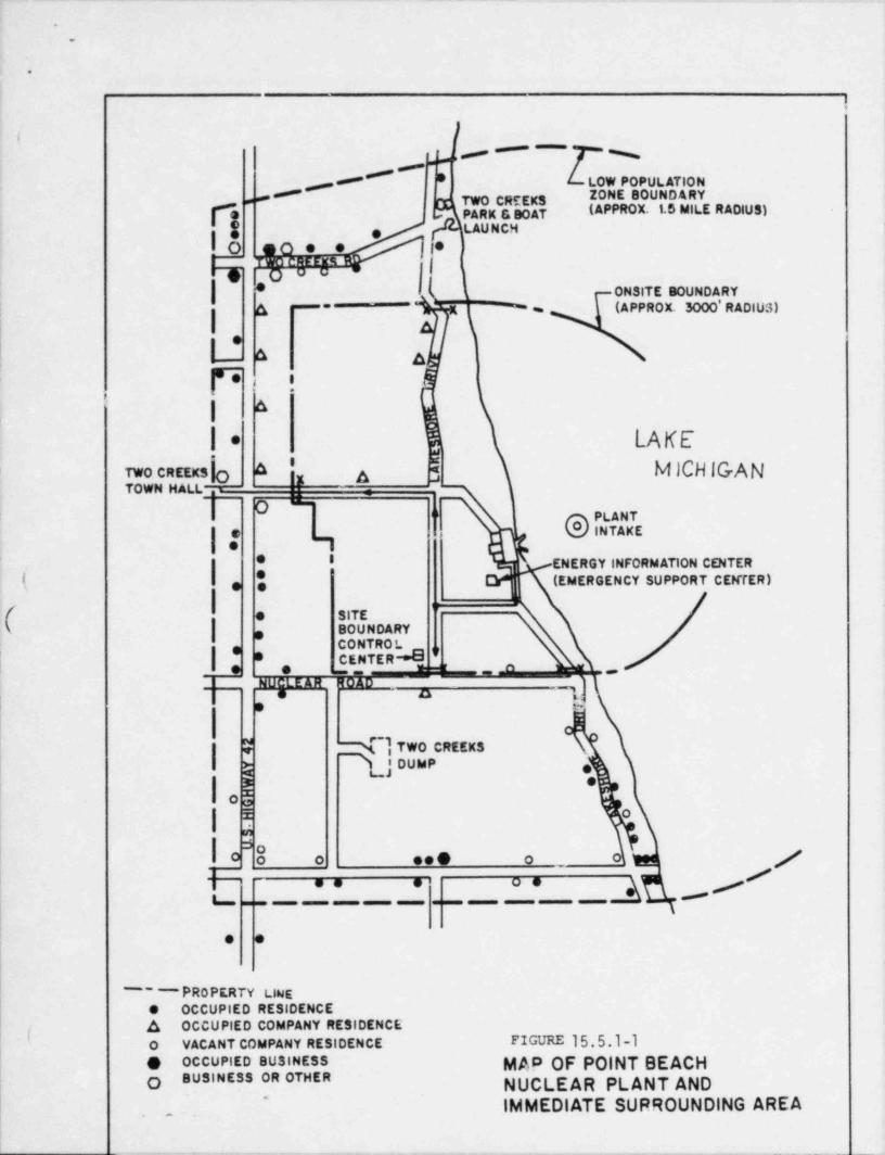
The Point Beach Nuclear Plant is located on property owned by the Wisconsin
Electric Power Company at a site on the shore of Lake Michigan, approximately
30 miles southeast of the city of Green Bay. The minimum distance from the
reactor containment center line to the property line as defined in 10 CFR
100.3 is 1,200 meters. The property line is identified on Figure 15.5.1-1.
i
15.5.1-1
I
||
|f . __ _ . _ _ _ _ _ . _ _ _ _ _ . _ _ _ _ _ . __ -- - - - . - - - ---_
. _ .
.
~
|
.
!
.=* :.
- ~*p# LOW POPULATION
ZONE BOUNDARY,d TWO CREEKS
(APPROX. l.S MILE RADIUS)='"
PARK & BOATi
LAUNCH :eIe ao e e \\e i
|$o{" T"!' - Il I
1( k j-ONSiTE eOUNDARYa (APPROX. 3000' RADIU3)" ' " " *
I g ~ = NLNL* s A
P,! <
''
|6
|* LAKE,
5 M ICH IGAN|x -ATWO CREEKS!OA
TOWN HALL [--
_
O ~' ' PLANT
e INTAKE
* I ENERGY INFORMATION CENTER
k I (EMERGENCY SUPPORT CENTER)e
( |e SITE
BOUNDARY,CONTROL
|ee "e CENTER M!e mwr ,nI .. _ ,,
NUCLEAR TOAD__
O
E () TWO CREEKS \I g jDUMP ,
IO !*
m
I ?'"
iD O
O O O 90 9 O q |j/h ee e oe _\
L.- _L. --___ .---
e e
- -PROPERTY LINEe OCCUPIED RESIDENCEA OCCUPIED COMPANY RESIDENCE
[O VACANT COMPANY RESIDENCE FIGURE 15.5.1-1e OCCUPIED BUSINESS MAP OF POINT BEACHO BUSINESS OR OTHER NUCLEAR PLANT AND
_IMMEDIATE SURROUNDING AREA
^
l
|_ . . - - . _ . - . . . .. - _.. -, , - _. _ _ , . . , . , . - . _ _ _ _ . - . . . - - . . - . . - _ _ _ - _ _ _ . . _ _ - _

_ _ _ .
:
|*
.
b) Review all proposed tests and experiments related to safety
and the results thereof when applicable.
c) Review all proposed changes to Technical Specifications.
d) Review all proposed changes or modifications to plant
systems or equipment where chcages would require a change in
operating or emergency procedures or that affect nuclear
safety.
e) Periodically review plant operations for industrial and
nuclear safety hazards.
f) Investigate violations or suspected violations of Technical
Specifications, such investigations to include reports,
evaluations, and recommendations to prevent recurrence, to
the Vice President - Nuclear Plant and to the Chairman of
the Offsite Review Committee.
g) Perform special reviews and investigations and prepare
reports thereon as requested by the Chairman of the Offsite
Review Committee.
h) Investigate, review, and report on all reportable
occurrences.
i) Cause to be conducted periodic drills on emergency
procedures, including evacuation (partial or complete) of
the site and check adequacy of communications with offsite
support groups.
j) Review the Facility Fire Protection Program and implementing
procedures at least once per 24 months.
15.6.5-3
. . - . . - . - . _ _ _ _ . _ . _- . _ _ . . . _

,
.
.
k) Review every onsite release of radioactive material to the
environs in excess of the levels calculated using the methodology
of the ODCM. Such review will include a summary of evaluation,
recommendation and disposition of corrective action to
prevent recurrence.
1) Review all proposed changes to the PCP and ODCH.
AUTHORITY
15.6.5.2.7
a) The Supervisory Staff shall serve as advisory to the Manager-Nuclear
Operations.
b) The Supervisory Staff shall recommend to the Manager approval
or disapproval of proposals under items a) through d) above.
In the event of disagreement between a majority of the.
Supervisory Staff and decisions by the Manager, the course
of action will be determined by the Manager and the disagreement
recorded in the Staff minutes. Records of the disagreement
will be included in the minutes sent for review to the
' Off-Site Review Committee and the Executive Vice President.
c) The Supervisory Staff shall make tentative recommendations
as to whether or not proposals considered by the Staff
involve unreviewed safety questions. These recommendations
shall be subject to review and further recommendations by
the Off-Site Review Committee. Minutes shall be kept of all
meetings of the Staff and copies shall be sent to the Executive
Vice President and to the Chairman of the Off-Site Review
Committee.
15.6.5-4
L
, . - - - , . _ . -- ,. - - _ . . . - - ,

-
.
.
d) The Supervisory Staff shall review and approve the contents
of a report for each reportable occurrence. This report
shall include an evaluation of the cause of the occurrence
and recommendations for appropriate action to prevent or
reduce the probability of a recurrence. Copies of all such'
reports shall be submitted to the Executive Vice PresidentJ
and to the Off-Site Review Committee.
RECORDS
15.6.2.8
The Manager's Supervisory Staff shall maintain written
minutes of each meeting and copies shall be provided to the
Executive Vice President and Chairman, Off-Site Review
Committee.
Ii
!
|
|
|
| 15.6.5-4a|!
-- . - - - .- - -- - ._. -- - - - -

!
1*
e
h) Any indication of an unanticipated deficiency in some aspects
of design or operation of safety-related structures, systems,
or components.
1) Reports and meeting minutes cf the Manager's Supervisory
Staff.
AUDITS,
15.6.5.3.8,
:
Audits of facility activities shall be performed under the cognizance
of the OSRC. These audits shall encompass:
a) The conforwance of facility operation to provisions contained
within the Technical Specifications and applicable license
conditions at least one per year.
b) The performance, training and qualifications of the licensed
operating staff at least once per year.
c) The results of actions taken to correct deficiencies occurring
in facility r.quipuent, structures, systems, or method of
operation that affect nuclear safety at least twice per year
at approximately six-month intervals.
d) The results of quarterly audits by the Quality Assurance
Division on the performance of activities required by the
Quality Assurance Program to meet the criteria of Appendix "B",
10 CFR 50, at least once per two years.
e) The Offsite Dose Calculation Manual and Process Control
Program together with their implementing procedures at least
once per two years.
15.6.5-7
--. _. --_ _--- -. .. - - -

_.
. - |
0
f) Any other area of facility operation considered appropriate
by the Executive Vice President.
'AUTHORITY
15.6.5.3.95
The OSRC shall report to and advise the Executive Vicee
,
President on those areas of responsibility specified ini
; Section 15.6.5.3.7 and 15.6.5.3.8.!
|,
i
1
a
1
I'
:I
i
i,
}
:
.
1
15.6.5-7a

_ ____ _ ..___ _ . _ _ _ _
..
o"
3. Observed inadequacies in the implementation of administrative or
procedural controls which threaten to cause reduction of degree
of redundancy provided in reactor protection systems or engincered
safety feature systems.
4. Abnormal degradation of systems other than those specified in
15.6.8.2.A.3 above designed to contain radioactive material
resulting from the fission process.
15.6,9.3 UNIQUE REPORTING REQUIREMENTS
The following written reports shall be submitted to the Director, Office of
Nuclear Reactor Regulation, USNRC:
A. Each integrated leak test shall be the subject of a cummary technical
report, including results of the locak leak rate tests and isolation
valve leak rate testr since the last report. The report shall include| analysis and interpretations of the results which demonstrate compliance
with specified leak rate limits.
B. If the confirmed measured level of radioactivity remains above the
notification levels specified in Table 15.4.10-2 of Specification
15.4.10, " Operational Environmental Monitoring", a written report
describing the circumstance shall be submitted to the NRC Regional
Administrator, copy to the above Director, within thirty days of the
confirmation.
C. Submission of a report within sixty days after January 1 and af ter
, July 1 each year for the six-month period of fraction thereof,
! ending June 30 and Decembcr 31 containing:,
15.6.9-7|
|
|
!
!1
- .- ---.._ - - - - ._ . . - , . . . . . . . - , .

--. . . - . - - -
.
.
(1) The number and types of samples taken and the types of
analytical measurements made on the samples.
(2) Any changes made in sample types or locations during the
reporting period and criteria for these changes.
b. A summary of survey results during the reporting period
including a comment on any significaat portion of the Operational
Environmental Monitoring Program not conducted.
4. Leak Testing of Source
Eesults of required leak tests performed on seal sources if the
tests reveal the presence of 0.005 microcuries or more of
removable contamination.
5. Meterological Data
The summary of required meterological data shall be kept in a
file on site and will be provided to the NRC upon request. The
annual summary may be either in the form of an hour-by-hour
listing on magnetic tape of wind speed, wind direction,
atmospheric stability, and precipitation (if measured) or in the
form of joint frequency distributions of wind speed, wind
direction, and atmospheric stability. The meterological data will
!be available following the installation and operation of the new
plant process computer and software (approximately 1985).
D. Poison Assembly Removal From Spent Fuel Storage Racks
Plans for removal of any poison assemblies from the spent fuel storage
racks shall be reported and described at least 14 days prior to the
15.6.9-10
_ _ - -_- -__ _ _ _ . _ _ . , . _ _ - _ _ _ _ -. __ _

.
o
planned activity. Such report shall descrite neutron attenuation
testing for any replacement' poison assemblies, if applicable, to
confirm the presence of boron material.
E. Overpressure Mitigating System Operation
In the event the overpressure mitigating systesa is operated to relieve
a pressure transient which, by licensee's evaluation, could have
resulted in an overpressurization incident had the system not been
operable, a special report shall be prepared and submitted to the
Commission within thirty days. The report shall describe the circumstances
initiating the transient, the effect of the system on the transient
and any corrective action necessary to prevent recurrence.
F. Dose Equivalent I-131
With total cumulative operating time at a primary coolant specific
activity greater than 1.0 microcurie per gram dose equivalent I-131
exceeding 500 hours in any consecutive six-month period, submit a
report within thirty days indicating the number of hours above this
limit.
G. Radioactive Liquid Effluent Waste Treatment.
If the radioactive liquid waste treatment system is inoperable and
liquid radwaste is being discharged for 31 days without the treatment
required to meet the design objectives set forth in 10 CFR 50, Appendix I,
a special report shall be prepared and submitted to the Commission
within thirty days which includes the following information:
1. Identification of the inoperable equipment or subsystem and the
reason for inoperability.
15.6.9-11
.
o
2. Actions taken to restore the inoperable equipment to operable
status.
* 3. Summary description of actions taken to prevent a re,currence.
H. Radioactive Gaseous Effluent Waste Treatment
If the radioactive gaseous waste treatment system and the ventilation
exhaust treatment system are inoperable and gaseous radwaste is being
discharged for 31 days without the treatment required to meet the
design objectives set forth in 10 CFR 50, Appendix I, a special report
shall be prepared and submitted to the Commission within thirty days
which includes the following information:
1. Identification of the inoperable equipment or subsystems and the!
reason for inoperability.t
2. Actions taken to restore the inoperable equipment to operable
status.
3. Summary description of actions taken to prevent a recurrence.
I. Radioactive Effluent Releases4
If the quantity of radioactive material actually released in effluents
! during any calendar quarter is such that the resulting radiation exposure,
.
calculated on the same basis as the design objective exposure, wouldi
exceed one-half the design objective annual exposure, a special report
: hall be prepared and submitted to the Commission within thirty days of
the analysis.
15.6.9-12
;
.. . _ . , . . _ . - _ - . . .. ..

*+
o'M. Test results, in units of sterocuries, for leak tests performed pursuant
to Specification 15.4.12.
N. Record of annual physical inventory verifying accountability of sources
subject to Specification 15.4.12.
O. * Records of training and qualification for current plant NRC licensed
staff and key personnel.
P. * Records of inservice inspections performed pursusat to these Technical
Specifications.
Q. * Records of Quality Assurance activities required by the QA Manual.
R. * Records of reviews performed pursuant to 10 CFR 50.59. ,
S. * Records of meetings of the Manager's Supervisory Staff and the Offsite
Review Committee.
T. * Records of Environmental Qualification which are covered under the
provisions of paragraph 15.6.12.
U. * Records of the service life of all snubbers in accordance with Specification
15.4.13.4.
V. * Record of analyses for radiological environmental monitoring.
f
* Items will be permanently retained.
i
15.6.10-2
. -. -. - _ ._-