proposed warehouse unit at mudarda village, mehsana,...
TRANSCRIPT
PRE ENGINEERED BUILDING, ROOFING, CLADDING & RELATED WORKS
FOR
PROPOSED WAREHOUSE UNIT AT MUDARDA VILLAGE,
MEHSANA, GUJARAT.
OWNER
FANIDHAR MEGA FOOD PARK PVT. LTD.
10/11, SECOND FLOOR,
ORCHID THE SHOPPING MALL,
OPP. THALTEJ LAKE,
THALTEJ, AHMEDABAD
GUJARAT-380059
PROJECT MANAGEMENT CONSULTANT TECHNOPAK ADVISERS PVT. LTD.
GURGAON
DESIGN CONSULTANT
VMS ENGINEERING & DESIGN SERVICES (P) LTD
CHITRAKOOT FLATS, B/H, TIMES OF INDIA,
OFF. ASHRAM ROAD, AHMEDABAD 380 009
PHONE: +91 (79) 2658 8829 – 2480 -4488,
FAX: +91 (79) 2658 3596
EMAIL: [email protected] ,
WEB: www.vmsconsultants.com

Consultant: VMS Engineering & Design Services (P) Ltd.
TABLE OF CONTENT: The tender document for Pre-Engineered Building including steel structure, roofing, cladding & related works for proposed plant of Fanidhar Mega Food Park Pvt. Ltd., at Mudarda village, Mehsana, Gujarat.
SECTION A: INVITATION TO TENDERER .................................................................................... 1
SECTION B: ELIGIBILITY CRITERIA ............................................................................................. 2
ANNEXURE 1 – EXPERIENCE OF SIMILAR PROJECTS ................................................................... 3
ANNEXURE 2 – DETAILS OF MANUFACTURING FACILITY ............................................................. 4
SECTION C: COMMERICAL CONDITIONS .................................................................................... 5
SECTION D: BUILDING DESCRIPTION AND RELATED SCOPE ............................................... 12
SECTION E: TECHINICAL SPECIFICATIONS ............................................................................. 14
SECTION F: QUANTITY SCHEDULE FOR PROPOSED PLANT ................................................ 19
SECTON G: PRICE SCHEDULE FOR PROPOSED PLANT ....................................................... 20
ANNEXURE 3 – SCHEDULE OF QUANTITIES AND PRICE ............................................................. 21
SECTON H: LOAD DATA FOR FOUNDATION DESIGN ............................................................ 23
ANNEXURE 4 – FORMAT FOR LOAD DATA ..................................................................................... 26
SECTION I : LIST OF DRAWINGS ............................................................................................... 27
Consultant: VMS Engineering & Design Services (P) Ltd. Page 1
SECTION A: INVITATION TO TENDERER
1.0 Sealed tenders in the prescribed form are invited on Lump Sum basis for the works mentioned below from Pre Engineered Building Manufacturing Firms of repute who have successfully executed similar nature of single work of not less than INR 10.0 Crore.
1. Tender Notice Number VMS/FMFPPL/PEB/11-2017
2. Name of Owner Fanidhar Mega Food Park Pvt Ltd.
3. Name of Work Design, Fabrication, Supply and Erection of Pre-Engineered Steel Building for Main Plant Building
4. Project Location Mudarda village, Mehsana, Gujarat
5. Period of Completion 30 Weeks
6. Date & Time of Tender Receipt and Opening
25-12-2017 before 3:00 PM
7. Place of Submission of Tender
FANIDHAR MEGA FOOD PARK PVT. LTD. 10/11, Second floor, Orchid The Shopping Mall, Opp. Thaltej Lake, Thaltej, Ahmedabad, Gujarat – 380059.
8. Time and Venue for Pre-bid Meeting
VMS Engineering & Design Services (P) Ltd. Chitrakoot Flats, Ground Floor, B/H Times Of India, Ashram Road, AHMEDABAD – 380 009, Gujarat 11-12-2017 at 11:00 AM
2.0 Completed Tender should be submitted in a sealed cover super scribing the Name of
work and Tender Notice number. 3.0 The tenderer shall return the duly filled in tender document after affixing signature on
all the pages of the Tender Documents.
4.0 Fanidhar Mega Food Park Pvt. Ltd. (FMFPPL), reserves the right to accept or reject any or all Tenders without giving any reasons thereof, in their sole discretion and without any liability or costs to the Tenderer(s). FMFPPL may further waive any deviations which do not constitute a material modification in the Tenders received. In the event that there are any other material deviations in the Tender FMFPPL may in their sole discretion reject and remove such deviations from the Tender and accept the same as per this Tender documents. The decision whether the deviation constitutes a

Consultant: VMS Engineering & Design Services (P) Ltd. Page 2
material modification shall solely be that of FMFPPL and such decision shall be binding on the Tenderer(s).
SECTION B: ELIGIBILITY CRITERIA
1.0 Average annual financial turnover during the last 3 years ending 31/03/2016, should
be at least Rs. 10 crore.
2.0 Experience of having successfully completed one similar project during the last 3 years as on 31/07/2016 for reputed private sectors and MNC should be mentioned in Annexure-1 below.-
3.0 The contractor should possess his own pre-engineering building components manufacturing facility and design capability. Details of the same shall be filled in Annexure-2.
Tender bids not meeting any of the above pre-qualification criteria shall be rejected.

Consultant: VMS Engineering & Design Services (P) Ltd. Page 3
ANNEXURE 1 – EXPERIENCE OF SIMILAR PROJECTS
Details required from PEB Supplier - for Projects completed in last 3 years and having value of single PEB Contract more than INR 10 crores.
Sr. no.
Name and Location of the Project Year Amount of
the PEB work in Rs.
Approx. area of building(s) for
which PEB Supplied
Duration of PEB works
(As per Agreement)
Actual Duration of PEB Works Completion
Name & Contact details of the
person in charge from Client's side
Note: Tenderer shall enclose completion certificates received from Client for projects listed above.
Consultant: VMS Engineering & Design Services (P) Ltd. Page 4
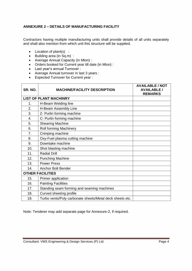
ANNEXURE 2 – DETAILS OF MANUFACTURING FACILITY
Contractors having multiple manufacturing units shall provide details of all units separately and shall also mention from which unit this structure will be supplied.
Location of plant(s) :
Building area (in Sq.m) :
Average Annual Capacity (in Mton) :
Orders booked for Current year till date (in Mton) :
Last year’s annual Turnover :
Average Annual turnover in last 3 years :
Expected Turnover for Current year :
SR. NO. MACHINE/FACILITY DESCRIPTION AVAILABLE / NOT
AVAILABLE / REMARKS
LIST OF PLANT MACHINRY
1. H-Beam Welding line
2. H-Beam Assembly Line
3. Z- Purlin forming machine
4. C- Purlin forming machine
5. Shearing Machine
6. Roll forming Machinery
7. Crimping machine
8. Oxy-Fuel plasma cutting machine
9. Downtake machine
10. Shot blasting machine
11. Radial Drill
12. Punching Machine
13. Power Press
14. Anchor Bolt Bender
OTHER FACILITIES
15. Primer application
16. Painting Facilities
17. Standing seam forming and seaming machines
18. Curved sheeting profile
19. Turbo vents/Poly carbonate sheets/Metal deck sheets etc.
Note: Tenderer may add separate page for Annexure-2, if required.
Consultant: VMS Engineering & Design Services (P) Ltd. Page 5
SECTION C: COMMERICAL CONDITIONS 1. Definitions In the Contract, as hereinafter defined, the following words and expressions shall have
the meanings hereby assigned to them, except where the context otherwise requires:
a. “Contract Period” shall mean the period during which the Contract shall be executed as agreed between the Contractor and the Owner in the Contract. The time limits stated in the Contract Document are the essence of the Contract.
b. The “Date of Virtual Completion” of a project or specified area of a project is the
date when construction is sufficiently completed, in accordance with the Contract Documents as modified by any change or variation orders agreed to by the parties, so that the Owner can occupy the project for the use it was intended.
c. The following words mentioned as such in the Contract Documents shall mean:
Owner: Fanidhar Mega Food Park Pvt. Ltd. (SPV)
Contractor: Successful Tenderer
Architect: VMS Engineering & Design Services (P) Ltd.
Design Consultant: VMS Engineering & Design Services (P) Ltd.
PM Consultant: Technopak Advisors Pvt. Ltd. Gurgaon.
Engineer: Representative of Fanidhar Mega Food Park Pvt Ltd.
And shall include their legal representatives, permitted assigns or successors as the case may be.
d. "Site" shall mean the place or places envisaged by the Owner, within the
Fanidhar Mega Food Park at Mudarda village, Gujarat where the Works have to be executed and shall include any building and erections thereon and any other land allotted by the Owner for Contractor's use.
e. The “Parties” shall mean the Owner and the Contractor stated herein.
2. Water & Electric Power for Construction
Electric Power Supply and Water required for construction or any other purpose for execution of this work shall be provided by the Owner to the Contractor at one point within the plot premises on chargeable basis. The Contractor shall make further arrangement for local distribution and installation of meter at his own cost. The contractor shall be permitted to set up the labour camp on plot premises.
3. Time of Completion and Milestones
Time period to complete all the Works covered within the Scope of this Contract shall be 30 weeks from the date of issuing the Letter of Intent (LOI).

Consultant: VMS Engineering & Design Services (P) Ltd. Page 6
Specific milestones shall be as given below –
Sr. Milestone Duration
1 Submission of DBR, Foundation load data (in a format as per Section-H) and Anchor bolt plan and section to start the foundation design work.
Within 1 Week
2 Submission of Detailed GA drawings for Getting Approval by consultant
2nd to 3rd Week
3 Review by consultant and Getting Final Approval of DBR and GA drawings.
3rd to 5th Week
4 Supply of Anchor Bolts at site along with adequate no. of templates.
3rd to 4th Week
5 Fabrication & Supply of Materials to Site (Material receipt to the site shall start latest from 8th week after LOI)
5th to 18th Week
6
Erection of building structure & roofing. Roofing work shall be handed over as and when completed for further Civil/Civil/another works below roof. Erection also includes Cladding works in Front, Rear, Sides including Fascia, Gutter and inside cladding works (if any) with provision of necessary Framed openings
12th Week to 22nd Week
7 Misc. works like Louvers, cage ladder, Canopy, balanced flashings, finishing, submission of as-built drawings and Handing over to Client
22nd to 30th Week
All days are calendar days to be calculated from the date of issuance of the Letter of intent by FMFPPL to the Contractor. 4. Design and Drawing Approvals
Process to be followed by Contractor for GA drawing Approval:
1. Understanding building requirements through tender drawings and specifications. Any queries shall be asked and resolved with consultant before submitting the offer.
2. Preparation of DBR, AB plans, GA drawings etc. as per Tender requirements and subsequent clarifications given in negotiation meetings and submission of same for consultant’s review. The submission shall be considered invalid (CAT-IV) if any major deviation from tender drawings and specifications is found. Upon review of drawings / documents, depending on the correctness and completeness of the drawing, the same will be categorized and approval accorded in one of the following categories:
CAT-I APPROVED - No Further Comments
CAT-II APPROVED Subjected to Incorporation of Comments as Marked.
CAT-III NOT APPRVOED - Resubmit with Incorporation of Comments as Marked / Discussed.
CAT-IV INVALID SUBMISSION - Due to Non-Conformity of tender specifications / drawings
Consultant: VMS Engineering & Design Services (P) Ltd. Page 7
3. If consultant insists, deploy design engineer and drafts person to consultant’s office
for making necessary corrections in the design/drawings. 4. Each submission and comments on that submission shall be recorded / documented
in predefined format. This log shall be maintained by contractor and to be submitted to consultant along with revised drawings and documents.
5. If contractor fails to get CAT-I approval of GA drawing and DBR from consultant in stipulated time period, liquidated damages shall be paid as per Clause (7) of this section.
6. The contractor must submit the Design basis report & Staad design file for record purpose only.
5. Schedule of works
The contractor shall submit detailed schedule in the form of a quantified bar chart or CPM network which includes all the activities from start to completion within 5 days from date of issuance of LOI for approval by Engineer / Owner / Consultant.
6. Co-ordination between different Agencies
The Contractor shall submit the details of Erection works programme to the engineer who will co-ordinate with the programme of the Civil / Mechanical / Electrical contractor separately submitted to him. Such co-ordination of Civil / Mechanical / Electrical and Erection works programme shall be agreed between the engineer, erection and civil works contractors and the agreed programme shall then be mutually binding on Contractors for Civil / Mechanical / Electrical & PEB Erection.
7. Liquidated damages
If the Work is not completed within the time of Completion stipulated above, pre-estimated genuine Liquidated damages at the rate of 1.25 % of the Contract value per week of delay (not to exceed 5 % of the Contract Value) shall be paid by the Contractor.
8. Rate to Include
Quoted rate shall be for finished work. Generally, it shall include for material, plant & tools, scaffolding, labour, incidental materials, fixing media, fixing, loading, conveying, delivery, unloading at Site, storing, returning, packing, handling, hoisting, lowering, insurance, waste, cutting, establishment costs, temporary works, tests, preliminaries, overheads, royalties, VAT, all taxes, profit and any other costs to complete the Work in its final form and state. GST, as applicable, shall be quoted separately. The quoted rate shall include for all the obligations to be fulfilled by the contractor as stated in the contract document. The quoted rate shall also include the additional work of up to 2% of Contract value, as mentioned in Section-G (Price Schedule)
9. Payment terms – The successful bidder is required to submit a Performance Bank Guarantee (PBG) of 5% of the Contract Value from a Nationalized Scheduled Bank within 15 days of the award of Work, which should be valid up to date of completion mentioned in the

Consultant: VMS Engineering & Design Services (P) Ltd. Page 8
contract. This PBG will not be monetarily reimbursed to the contractor at any stage of the project.
For Supply a) 20% of the Contract Value - as an Advance against submission of a Bank
Guarantee from a Nationalized Scheduled Bank of equivalent amount valid up to the total recovery of advance payment.
b) 5% of the Contract Value - against Submission of CAT-I approved GA drawings and DBR for record. Without completing this stage, further payments will not be made even if the material supply is started at site.
c) 75% of the Contract Value - against receipt of materials at site on pro-rata
basis (Subject to progress of Erection works as per agreed schedule). Schedule of material dispatch shall be got approved with Engineer-in-charge prior to start the dispatch.
For Erection
Sr. No. Description % of Erection
Amount
a) Mobilization Advance (After Erection Gang reaches at Site with necessary erection drawings and erection plans)
20%
b)
Erection of Primary Structural Members such as Main Columns, Rafters, Gantry girders, Gable end columns, bracings, purlins, tie beams etc. and alignment of structure duly approved by Engineer.
30%
c) Fixing of Roof and Wall Sheeting along with Insulation, Flashings, Gutter, Down takes etc.
30%
d) Erection of balance materials like cladding, flashing, Turbo vents, Canopies, accessories etc.
10%
e) On completion and handing over of works in all respect 10%
10. Retention
From each bill (either for supply or for erection) the Owner will hold 5% amount as Retention. This 5% retention amount will be released after Virtual completion of the project against Bank Guarantee which shall remain valid up to Defects Liability Period.
11. The Setting Out and Structural Alignment The Contractor shall at his own expense, set out the works accurately in accordance with the plans. The Contractor shall be solely responsible for the true and perfect setting out of the works, and for the correctness of the position, levels, dimensions and alignment or all parts thereof. If at any time any errors shall appear during the progress or on completion of any part of the work, the Contractor shall at his own cost rectify such error if called upon to the satisfaction of the Owner. The work shall from time to time be inspected by the Owner and/or his/their representatives but such inspections shall not exonerate the Contractor in any way from his obligations to remedy any defects which may be found to exist at any stage during the work or after the work is completed.

Consultant: VMS Engineering & Design Services (P) Ltd. Page 9
12. Survey and Level/Setting out Work It shall be the responsibility of the Contractor to verify the placing and fixing of Anchor Bolts by the Civil Contractor. An Inspection Engineer is required to be deployed during the execution of this activity without any additional cost, to verify the levels, alignment and correct positioning of bolts.
13. Defect Liability Period: The Contractor shall make good at his own cost and to the satisfaction of the Engineer, all defects, shrinkages or faults, arising in the opinion of the Engineer from work or materials not being in accordance with the Drawings or Specifications or the Instructions of the Engineer, which may appear within "Defects Liability Period" of Eighteen (18) months from the date of Virtual Completion. If the Contractor refuses/ fails to make good the defects or faults, Owner may, in lieu of such amending and making good by the Contractor deduct from any moneys due to the Contractor (including the Performance Bank Guarantee), a sum to be determined by the Engineer as equivalent to the cost of amending such work and in the event of the PBG Amount being insufficient, recover the balance from the Contractor, together with any expenses the Owner may have incurred in connection therewith.
14. Insurance
a. The Contractor shall indemnify the Owner and every member, Officer, and
Employee thereof and the Engineer and the Engineer's Agents and Representative and every member of his staff from any claim or demand from accident, injury, damage, loss and/or compensation of any kind whatsoever arising out of or in connection with all claims and demands which may be made against the Owner or the Engineer for or in respect of or arising out of failure by the Contractor in the performance of his obligation under any of the provisions of the Contract. The Contractor shall take necessary insurance to protect himself against claim or demand.
b. Without prejudice to his liability to indemnify the Owner under Article (a) of these
Conditions, the Contractor shall maintain and shall cause any Sub- Contractor to maintain: -
Such insurances as are necessary to cover the liability of the Contractor or as the case may be of such Subcontractor, in respect of personal injuries or deaths arising out of or in the course of or caused by the carrying out of the work; and Such insurances as may be specifically required by the Contract Bills in respect of injury or damage to property real or personal arising out of or in the course of or by reason of the Contractor or his Sub-Contractor carrying out the work, and caused by any negligence, omission or default of the Contractor, his servants or agents or, as the case may be of such Sub- Contractor, his servants or agents.
c. The Contractor shall obtain and maintain a comprehensive all risk policy which
should also cover insurance against loss or damage by fire, storm, tempest, lightning, flood, earthquake, aircraft or anything dropped there from, aerial objects, riot and civil commotion for the full value thereof all work executed and all unfixed materials and goods intended for, delivered to and placed on or adjacent to the work until Virtual Completion of the work. Should the Contractor make default in
Consultant: VMS Engineering & Design Services (P) Ltd. Page 10
insuring or continuing to insure as aforesaid the Owner may himself insure against any risk with respect of which the default shall have occurred and deduct a sum equivalent to the amount paid by him in respect of premium from any monies due to or to become due to the Contractor.
15. Approval by the Owner / the Engineer
Any approval or any approval given with changes, by the Owner, Engineer or their representative shall not relieve the Contractor of any of its obligation, responsibility and liability for the safety, correctness and performance of the Works and his obligations hereunder including drawings and design.
16. Storage & Safety of Materials
It will be Contractor’s responsibility to unload and store materials properly. Safety of materials received at site will be Contractor’s responsibility. Client will not inspect materials and Contractor will be responsible for it till the handover of site. a. It will be contractor’s responsibility to unload and store material (fabricated/non-
fabricated steel sections, sheeting, purlins, accessories, etc.) at site properly.
b. Structural steel shall be stored out of mud and dirt. Proper drainage of the storage area shall be provided. These shall be protected from damage or soiling by adjacent construction operations.
c. Fabricated steel shall not be handled until the paint has thoroughly dried. Care shall be taken to avoid paint abrasions and other damage. Steel work shall be transported in such a way so as not to over stress the fabricated sections. All pieces bent or otherwise damaged shall be rejected and shall be replaced by the contractor at his own cost.
d. The contractor to ensure that fabricated steel work is properly stacked such that all joints of all members are either visible or accessible for inspection at all stages of inspection work. Care should also be taken to ensure that fabricated members are not subjected to stresses due to defective stacking.
e. Insulation and other water or dust sensitive materials shall be stored properly in
hard enclosure and with care to avoid damage.
17. Safety a. Workers required to work at higher elevations shall be provided with safety belts
and shall be instructed not to work without wearing the Belt. b. Good quality safety helmets shall be provided to Workers posted at Site of
operations and Contractor will take adequate measures to make usage of these helmets mandatory.
c. When persons are employed on a roof, where there is danger of falling from a
height exceeding 3.25 m., suitable precaution shall be taken to prevent the fall of persons or material. Suitable precautions shall also be taken to prevent persons being struck by articles, which might fall from scaffolds or other working places.
Consultant: VMS Engineering & Design Services (P) Ltd. Page 11
d. In general, the Contractor shall adhere to safe construction practice and guard against hazardous and unsafe working conditions and shall comply with Owner’s safety rules.
e. The Contractor shall adhere to all safety rules and regulations as indicated under attached OHS Manual.
18. Project Completion and Handover
a. Clearing of site and handing over of all the works, as directed by Engineer-In Charge,
b. Maintenance of the completed work during the maintenance period, The “Maintenance Period” for the works done by contractor under this contract will be One Year from the date of actual completion of the particular work and handing over to Client.
c. The contractor shall submit to the Owner “As Built” drawings in 3 sets of copies along with other related documents.
d. Ensuring structural stability and safety during and after construction. Issuance of stability certificate.
Any other requirement for the commissioning of the building in all respects in accordance with the provisions of this Contract
Consultant: VMS Engineering & Design Services (P) Ltd. Page 12
SECTION D: BUILDING DESCRIPTION AND RELATED SCOPE
Proposed Main Plant Building: Drawings showing Plans at various levels, Elevations, Sections and other necessary building details are attached with this Tender. The list of tender drawings is given in Section-I.
Scope of work includes Designing, supplying & erecting all the components of Steel Building as per the specifications and drawings. The Steel Building components include –
1. Structure for proposed Main plant as shown in the tender drawings. 2. Roof sheeting – as showed in the tender drawings. 3. Side cladding sheets for external walls as showed in tender drawings. 4. All fascias (if any) shall have color coated Galvalume trapezoidal profiled sheets
at front, Bare Galvalume sheets at top & Bare Galvalume trapezoidal profiled sheets at the back side.
5. All accessories like aprons pieces, corner pieces, ridges, clamps, bottom trims,
facia cap, closure trim, drip trim etc. 6. Structure as well as Sheeting for canopies (with framing) as shown in tender
drawings.
7. All canopies shall be cladded at side and from ceiling with Galvalume Sheeting with provision of Gutter, downspout, cutout for electrical fittings etc. as per approved details.
8. Foundation bolts for all columns along with required set of templates. Templates
for bolts shall be made with MS plate and shall have adequate stiffness to avoid sagging. Contractor to deploy his supervisor to check & verify dimensional accuracy of anchor bolts including bolt levels before and after concreting of pedestals. In case of minor deviation in bolt locations or levels, the Contractor shall make necessary adjustments in base plate holes/structure after approval of Engineer.
9. Cage Ladders with locking system as shown in the drawings (having same color
as of cladding sheet) having small platforms with railing at intermediate levels and at top, to go up to the roof for maintenance. Intermediate platform shall be located such that climbing height of cage ladder will not exceed 6m.
10. Structural steel Framing and flashings/ fascia around the openings – for fixing
louvers, vents, windows, doors, rolling shutters, etc. Considering the size of the Rolling shutters, particular attention shall be paid to the design/ size of the framing provided to support the Rolling shutters.
11. Supply & erection of Rolling shutters, doors, AL. louvers, vents, windows, etc.,
which are to be fixed in brick masonry wall – are NOT in the PEB supplier’s
Consultant: VMS Engineering & Design Services (P) Ltd. Page 13
scope, unless specified in Tender drawings. However, structural framing required for fixing/ support the rolling shutters (along-with its housing) & doors shall be in PEB supplier’s scope. Only box type members having minimum dimensions of 200mm x 200mm to be used for framed opening of rolling shutters. Additional horizontal members for supporting the Housing shall also be provided as per details of Rolling shutter supplier. The framed opening details shall be got approved with Rolling shutter supplier.
12. 2 mm thick Poly Carbonate translucent sheets (skylights) as shown in tender
drawings. GI welded wire mesh of 14G to be provided below polycarbonate sheet for safety. Additional cold formed members shall be provided on edges of polycarbonate sheet across the purlin and GI Wire mesh to be tied properly with purlins and these additional members.
13. Roof monitor with bird mesh to be designed for 6 air changes/hour at all areas
assuming that the air intake through louvers as shown in drawing. Further to this the minimum width and height of the Roof Monitor shall be as per the tender drawings.
14. Provision for laying GI Strip of earthing conductors for lightening on roof shall be
considered. Supply and installation of GI strip shall NOT be included in the present Scope.
15. Provision of Photovoltaic Solar panel fixing over roof sheets.
16. The utility racks passing along PEB columns supported on brackets at PEB
column similarly, Cable rack passing along PEB columns supported on PEB column as shown in the tender drawings. Supporting structure consisting of beam, bracket and ties for utility and cable racks are in PEB’s scope. The loads provided in the drawings are excluding self-weight of pipe rack / brackets / supporting structure.
17. Bracings can be X- type bracings. Bracings shall be made with Hollow steel
sections or Angle sections only. MS Rods are not allowed for bracings. Location of braced bay to be decided at GA approval stage.
18. The building shall be made reasonably dust proof by providing Foam Filler at following areas –
Roof gutter and roof sheeting junctions
Roof gutter and wall cladding junctions
Cladding sheet and brick wall junctions with drip trim
Flashing and Sheeting junctions
Ridge cap and roof sheet junction.
Any other junctions in the building which are prone to invite dust.
Consultant: VMS Engineering & Design Services (P) Ltd. Page 14
SECTION E: TECHINICAL SPECIFICATIONS
General: The technical specifications, design considerations and Scope of supply given below are for the general guidance of the Tenderer and shall not be considered as exhaustive. Structure shall be designed for the satisfactory performance of the functions for which the same is to be constructed. Details/ specifications not appearing in the list, but required to complete the work, shall be considered as part of the Scope and Tenderer’s offer shall be considered to include the same. If the Tenderer has contemplated any variation in specifications/ scope described below, the same shall be clearly mentioned in a separate statement attached with his offer.
Loading
The structure shall be designed for all loads, including the weight of structure, live load, crane load with impact, wind or earthquake. Due consideration shall be given to loading during the construction/erection phase and accounted for in the design. The design to be caters for the proposed future expansion also.
1. The Loads to be considered for analysis and design of structure shall be as follows –
a. Dead Load - As per IS : 875 (Part 1) - 1987
b. Live Load - As per IS : 875 (Part 2) – 1987
c. Wind load - As per IS : 875 (Part 3) - 2015
Basic wind speed = 47 m/sec k1 = 1 k2 = Terrain Category 3 k3 = 1 k4 = 1 ka, kd, kc = As per the Criteria given in Code
d. Earthquake load - As per IS : 1893 (Part 4) – 2016
Earthquake Zone = III
2. Purlins shall be capable of taking minor additional loads of fixtures like light fitting as normally encountered in Industrial buildings – unless specified elsewhere.
3. Following collateral or service loads shall be considered on PEB structure, in addition to the normal dead loads, live loads, gantry loads & wind loads –
a. Utility racks to support piping and cable trays and other collateral loads –
Load considerations for PEB shall be as per tender drawings
b. PV solar panels - 25 kg/m² (on purlins). c. Fire Sprinkler - 25 kg/m² (on purlins & rafter).
Consultant: VMS Engineering & Design Services (P) Ltd. Page 15
Analysis and Design 4. Design of steel structure to be as per latest versions of IS CODE. The Tenderer
shall clearly specify the design codes considered by him in preparing his offer.
5. The Bottom of Base plate level (BOBP level) of Steel columns – i.e. junction between Steel column and RCC pedestal shall be kept at FF Level.
6. Hooked anchor bolts (Either J-type or L-type) is not allowed. Straight type
foundation bolts with adequate sized end plate/end nut shall be provided. Supplier shall also specify the minimum distance of Foundation bolts to be maintained from edge of RCC pedestal as per design pull-out strength of anchor bolts. The vendor should consider RCC grade for Pedestal as M-25 for anchor bolt design.
7. All the columns of all frames shall be considered as Pinned at base (at junction
of structural steel column with RCC pedestal). Frames/ structure shall be designed accordingly. However, it is important to note that RCC pedestals are rested on foundation having approx. 3.5m depth from FFL. The type of foundations for this building will be isolated foundations.
8. Tie beam/Strut pipe shall be provided at Top of each column along the full length
of the building. 9. Details of Brackets and beams for support of cable trey or utility pipes shall be
got approved with Consultant. 10. Complete responsibility of the structural design of the building shall remain with
the Supplier. The Supplier shall submit design basis report for the approval of the Owner/ Consultant prior to taking up the design work.
11. Spacing of purlins to support Galvalume Roofing shall not be more than 1.4 m c/c and the same for Galvalume Cladding sheets shall not be more than 1.5 m c/c.
12. Roof slope of the building shall be as per the tender drawings. This slope has to be confirmed by the Tenderer in respect of the guarantee against leakages sought vide a separate clause of this Document.
13. Openings shall be provided as per Tender drawings without any deviations and
the same shall be confirmed by the Bidder while submitting his Offer. All openings in roof & cladding sheets shall be sealed to ensure no water leakages in future. Framed opening details shall be got approved from the consultant in GA drawings and by making a sample at site as well.
14. Contractor shall consider 2 nos. additional framed openings in cladding having
approx. size of 500mm x 500mm. Location and level of these openings are not final at this stage. It will be decided based on client’s requirement during the erection work.

Consultant: VMS Engineering & Design Services (P) Ltd. Page 16
Material and Related Specifications
15. All structural steel used shall be either of Fy = 350 MPa or Fy= 250 MPa as per IS: 2062-2011 and manufactured by SAIL, TATA, JINDAL or ESSAR.
16. All structural steel primary members (including cleats, brackets, sag rods,
bracings, stays etc.) shall be shot-blasted (S.A 2.5) and painted with a coat of Epoxy primer to provide minimum Dry Film thickness of 50 micron at the Fabrication shop. The structural steel shall be cleaned and applied two coats of approved Epoxy Paint at shop to provide minimum Dry Film thickness of 50 ± 5 micron for each coat. The interval between two coats should be 24 hours. Touch up coat of same paint at site shall be provided before erection, as required. Total paint thickness shall not be less than 150 micron DFT at any surface. The surfaces at connections (laps) shall receive both the coats properly at shop. Final touch up of same color shall be made after erection also.
17. All secondary members shall be made of cold formed sections having min. yield
strength of Fy = 280 MPa. 18. All cold formed sections should be pre galvanized having minimum 275 GSM
thickness of Galvanizing. 19. All Galvalume cladding sheet panels (outside and internal partitions, if any)
shall be Hi-rib (trapezoidal) Silicone Modified Polyester coated (SMP coated) 26 gauge (min. 0.50 mm TCT) pre-color coated Galvalume sheets of min. 550 Mpa yield strength.
20. Galvalume roofing sheet panels as shown in the drawings shall Standing
Seam profile type panels Silicone Modified Polyester coated (SMP coated) 24 gauge (min. 0.58 mm TCT) pre-color coated Galvalume sheets of min. 345 Mpa yield strength.
21. Galvalume roofing and cladding sheets shall be produced out of Tata BlueScope
/ Dongbu / JSW made coils. The sheets shall be of AZ 150 class (Aluminum zinc coating of 150 grams per sq. meter.) with coated alloy of 55% Aluminum, 43.5% Zinc and 1.5% Silicon and of approved color with top surface coated with 20-25 microns of coating (including 5-micron epoxy primer) and bottom service coat with 10-15 microns. Sheet material & painting shall confirm to ASTM standards ASTM A 792 & ASTM A 755. Sample and shade of the sheets shall be got approved from the Engineer prior to the procurement.
22. The Bidder will provide the material test certificate for all the material coming to site.
23. Fasteners used for fixing the sheeting panels shall be approved make self-
tapping type with metal washer & neoprene washer and shall have matching color hex. Head. Preferred make Coroshiled, Hilti or equivalent.
24. Lapping of sheeting panels at sides & ends shall have 6 mm wide x 5 mm thick
butyl tape sealer having nontoxic, non-shrinking, nondrying and non-asphaltic properties.

Consultant: VMS Engineering & Design Services (P) Ltd. Page 17
25. Solid or closed cell Ethylene Polypropylene Terpolymer type Foam filler/ closures having same profile as sheeting panels shall be provided at eaves, ridge & other locations as per industry norms & good engineering practice to make the building reasonably dust proof.
26. Supplying & fixing 4 mm radiant heat reflective insulation material for roofing
made of polyethylene air bubble film of Aerolam make or approved equivalent, laminated with aluminum foil on both side etc. complete as per manufacturer’s specification including placing, fixing with wire mesh, jointing, tapping, etc.
27. Roof as well as wall cladding of the building shall have 2 mm thick UV Resistant
Poly Carbonate translucent sheets of GE, Lexan or equivalent make, as approved by the Engineer-in-charge. PC sheets shall have same profile as roofing / cladding sheets. PC sheets shall be provided as shown in attached tender drawings.
28. Gutter size shall be adequately designed for minimum 50 mm/hour rainfall
intensity and shall be made out of min. 3 mm thick black M.S. Sheet having min. yield strength of 240 Mpa. Gutter shall be shot blasted on both inner and outer side. 1 coat of Epoxy primer + 2 coat of PU paint shall be applied at both inner side and outer side of gutter for anti-corrosion. After erection, all joints of gutter shall be coated with anti-corrosive & waterproof paint (Kemper or approved equivalent) over primer as per paint manufacturer’s specifications on the inner side.
29. Downspouts shall be adequately sized, in adequate numbers and shall be made of 26 G color coated galvanized plain sheet. Each down spout shall have an elbow at the bottom and shall be supported by attachment to the wall cladding at maximum 3 m. centers, if required.
30. Galvanized Welded wire mesh of 50x50x2 mm shall be provided and fixed in
proper position as shown on drawing including structural supports and making doors including hardware as required.
31. Liner Panel at loading area - Low-rib (trapezoidal) regular modified polyester
coated (RMP coated) 26 gauge (min. 0.50 mm TCT) pre-color coated galvalume sheets of min. 550 Mpa yield in RM/FG area under the roof insulation. Insulation shall be fixed with the liner panel with approved adhesive.

Consultant: VMS Engineering & Design Services (P) Ltd. Page 18
Corporate Warranty 1. The Tenderer shall give a guarantee against leakages through roof, sides and
gutter for a minimum period of 10 years. If water leakage will happen after handing over, the contractor shall respond immediately and arrest the leakage points/areas within 5 days.
2. The tenderer shall provide Structural stability certificate with mentioning design life of the structure, which is expected to be more than 30 years for this building.
Notes: 3. Offer with any major deviation in the proposed architectural scheme SHALL NOT
be accepted. 4. The Tenderer shall attach a statement with his Offer, clearly specifying minor
variations contemplated, if any, in preparing his Quote.
Consultant: VMS Engineering & Design Services (P) Ltd. Page 19
SECTION F: QUANTITY SCHEDULE FOR PROPOSED PLANT
1. Tenderer shall provide Schedule of net Quantities (excluding wastages) of his offer as per the Annexure-3. Offer without the appropriately filled data in Annexure-3 shall not be acceptable.
2. Maximum tolerance allowed in Total Weight of Structure will be 3%. If actual weight of structure erected at site (i.e. Material received at site – Wastage material after completing erection) is lesser than 3% of the weight committed above, Supply cost will be reduced per tonnage basis.
Case:
A = Structure material received at site (in MTon)
B= Wastage of structure material after completing erection (in MTon)
C= Net weight of structure material (in MTon) (= A - B)
D= Weight of structure committed for the project in Annexure-4.
T= Weight tolerance (in %) = (D-C) / D * 100 (Maximum 3% is allowed)
If C < 97% * D, Supply cost will be reduced per tonnage basis.
If C > 103% * D, No extra amount shall be payable to contractor.
3. The Total Weight of Structure will mean and include the weight of Primary & secondary structural members (including cold formed sections, cleats, sag rods, bracings, hardware etc.), Sheeting and related accessories, MS Gutter & Down take pipes etc. Insulation, Turbovents, ACP sheets, PC sheets and any other non-metallic part shall not be included in weight calculations.

Consultant: VMS Engineering & Design Services (P) Ltd. Page 20
SECTON G: PRICE SCHEDULE FOR PROPOSED PLANT 1. Tenderer shall provide detailed breakup of his offer quoted above in Annexure-3. Offer
without the appropriately filled data in Annexure-3 shall not be acceptable. 2. In case of any additional work over and above the work mentioned in this tender
document or drawings and to be executed at the Site within project duration, contractor shall be bind to take up the same on top priority to match with the project schedule and milestones. The contractor shall not be paid any extra amount for such additional works up to 2% of Contract value.

Consultant: VMS Engineering & Design Services (P) Ltd. Page 21
ANNEXURE 3 – SCHEDULE OF QUANTITIES AND PRICE
SR. NO. ITEM DESCRIPTION UNIT QTY. UNIT RATE
(IN INR)
AMOUNT (IN INR)
REMARKS
(A) PRIMARY STRUCTURE
1 Steel structure Mton
2 Cold formed Sections Mton
3 Utility trey bracket and runners Mton
4 False ceiling & Duct supporting structure Mton
5 Cage Ladder, Stairs, Railings Mton
6 Grating Mton
7 Chequred Plates Mton
8 Metal Deck sheet Mton
9 MS Gutter Mton
10 Roof monitor Mton
SUBTOTAL (A)
(B) SHEETING AND ACCESSORIES
11 Galvalume Roof sheets Mton
11a Aluminum Roof Sheet Mton
12 Cladding sheet Mton
13 Flashing & Trims Mton
14 Gutter made with Galvalume sheet Mton
15 Downspouts Mton
SUBTOTAL (B)
TOTAL WEIGHT OF STRUCTURE (A) + (B) = Mton
(C) OTHER ITEMS

Consultant: VMS Engineering & Design Services (P) Ltd. Page 22
SR. NO. ITEM DESCRIPTION UNIT QTY. UNIT RATE
(IN INR)
AMOUNT (IN INR)
REMARKS
16 Polycarbonate Sheets Sq.M.
17 Turbo Vents Nos.
18 Louvers Sq.M.
19 Bird mesh Sq.M.
20 ACP work - including required framing Sq.M.
21 Bubble wrap insulation with wire mesh Sq.M.
SUBTOTAL (C) Rs.
(D) ERECTION
21 Cost of Erection and Commissioning work Rs.
SUBTOTAL (D)
(E) TAXES AND DUTIES
22 GST on Supply Rs.
23 GST on Erection Rs.
SUBTOTAL (E) Rs.
SUMMARY OF COST
COST OF SUPPLY (A) + (B) +(C) Rs.
COST OF ERECTION (D) Rs.
COST FOR TAXES & DUTIES (E) Rs.
TOTAL COST OF WORKS Rs.
Consultant: VMS Engineering & Design Services (P) Ltd. Page 23
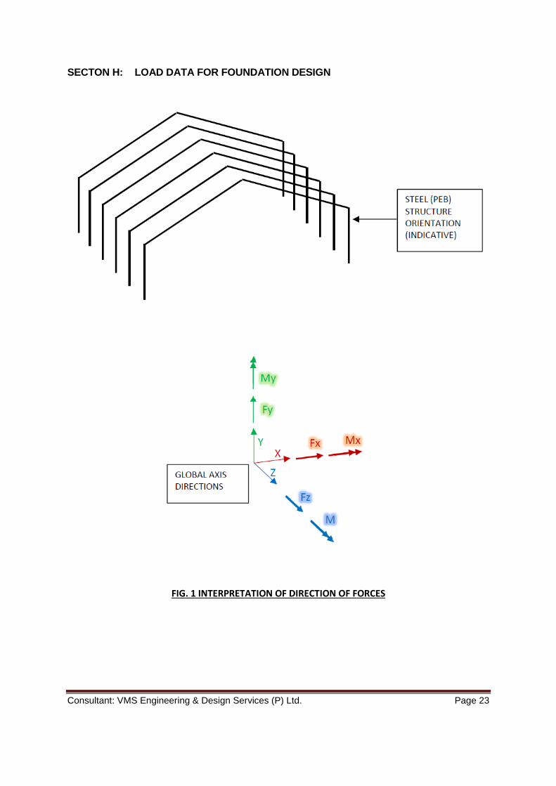
SECTON H: LOAD DATA FOR FOUNDATION DESIGN
FIG. 1 INTERPRETATION OF DIRECTION OF FORCES
Consultant: VMS Engineering & Design Services (P) Ltd. Page 24
NOTES:
1. All forces shall be of "Load-Action" type and not "Reaction" type. Loads given by PEB Supplier shall be directly used as it was given for further design of foundations. No change is sign (i.e. Positive (+) or Negative (-)) will be done by structural designer of foundation system.
2. All loads shall be provided with Unit as KN for forces & KN-m for bending moments.
3. All loads shall be un-factored.
4. Separate and typical loads for bracing system shall not be given. Each load case at each support location shall consists of total loads arising along the frame and across the frame (due to bracings).
5. Notations & signs of all forces shall be as per the global axis directions with respect to the PEB structure as shown in Fig. 1 above.
6. All loads shall be for primary load cases, not load combinations.
7. All loads shall be listed node wise as per format given in Annexure-4. For
identification of Node nos. with reference to AB plan, separate drawing or sketch shall be issued along with Load Data submission.
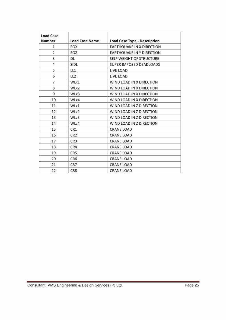
8. Name of Load Case and Load Number shall be followed as given in Table below. If
any Load case is not applicable to the proposed structure, value of the same shall be put as 0 (“zero”).
Consultant: VMS Engineering & Design Services (P) Ltd. Page 25
Load Case Number Load Case Name Load Case Type - Description
1 EQX EARTHQUAKE IN X DIRECTION
2 EQZ EARTHQUAKE IN Y DIRECTION
3 DL SELF WEIGHT OF STRUCTURE
4 SIDL SUPER IMPOSED DEADLOADS
5 LL1 LIVE LOAD
6 LL2 LIVE LOAD
7 WLx1 WIND LOAD IN X DIRECTION
8 WLx2 WIND LOAD IN X DIRECTION
9 WLx3 WIND LOAD IN X DIRECTION
10 WLx4 WIND LOAD IN X DIRECTION
11 WLz1 WIND LOAD IN Z DIRECTION
12 WLz2 WIND LOAD IN Z DIRECTION
13 WLz3 WIND LOAD IN Z DIRECTION
14 WLz4 WIND LOAD IN Z DIRECTION
15 CR1 CRANE LOAD
16 CR2 CRANE LOAD
17 CR3 CRANE LOAD
18 CR4 CRANE LOAD
19 CR5 CRANE LOAD
20 CR6 CRANE LOAD
21 CR7 CRANE LOAD
22 CR8 CRANE LOAD

Consultant: VMS Engineering & Design Services (P) Ltd. Page 26
ANNEXURE 4 – FORMAT FOR LOAD DATA
GRID REFERENCE
NODE NO.
LOAD CASE NAME
LOAD DATA
Fx (KN)
Fy (KN)
Fz (KN)
Mx (KN.m)
My (KN.m)
Mz (KN.m)
Above table shall be filled and provided in MS-Excel sheet format only.

Consultant: VMS Engineering & Design Services (P) Ltd. Page 27
SECTION I : LIST OF DRAWINGS
WAREHOUSE BUILDING
SR. NO DRAWING NO TITLE
1 T.A.40.101 GROND FLOOR AND ROOF PLAN
2 T.A.40.201 SECTIONS AND DETAILS
3 T.A.40.301 ELEVATIONS