prospects for improving machining productivity of large ceramic objects for radio engineering...
TRANSCRIPT
PROSPECTS FOR IMPROVING MACHINING PRODUCTIVITY
OF LARGE CERAMIC OBJECTS FOR RADIO ENGINEERING PURPOSES
E. I. Suzdal’tsev,1 D. V. Kharitonov,1 G. A. Kharakhonov,1 A. G. Épov,1 and M. V. Nogarev1
Translated from Novye Ogneupory, No. 12, pp. 17 – 24, December 2011.
Original article submitted September 22, 2011.
Contemporary machining methods for ceramic materials are analyzed. Laser, hydroabrasive and high-speed
machining are considered. The possibility of using these methods for machining large complexly-shaped ce-
ramic objects having a double surface curvature is evaluated.
Keywords: glass ceramic, machining, laser machining, hydroabrasive cutting, high-speed machining.
The rapid development of science and technology in re-
cent years has led to a situation that objects for radio engi-
neering purposes made from ceramic and glass ceramic ma-
terials have high specifications with respect to shape accu-
racy in longitudinal and transverse sections, wall profile, and
surface quality. Recently considerable experience has been
accumulated for machining large ceramic objects or radio en-
gineering purposes, having double surface curvature, includ-
ing diamond grinding by programming and copying of the
internal and external surfaces of an object [1 – 4].
For example, studies carried out by us previously [3, 4]
have made it possible to determine the range of values of op-
timum diamond tool properties, cutting force, and direction
of feed for grinding large ceramic objects with double sur-
face curvature, which currently are used successfully in pro-
duction (Table 1). However, the steady increase in the level
of specifications for quality indices and machining produc-
tivity, development and creation of new materials, specify a
requirement for improving existing technology, equipment,
and tools.
As an example the average machining duration for one
ceramic object for radio engineering purposes having an in-
ternal diameter of 200 and height of 600 mm, by existing
technology (see Table 1) is 40 – 45 h, which is caused by the
considerable thickness of production allowances, and also a
requirement for reinstalling a component in a lathe in order
to provide the required geometry and contour. In view of this
it is desirable to carry out work for studying the possibility of
intensifying machining.
The problem of intensifying machining ceramic compo-
nents, including large objects for radio engineering purposes,
has received considerable attention in domestic and overseas
publications. In [5] it is proposed to introduce a systematic
approach to ceramic component machining. It includes the
following operations: choice of the required collection of
tools for machining a specific type of component, which
makes it possible to shorten the time for changing a tool and
overcome its dimensional nonconformities; development of
monitoring for a machine component geometry during inter-
Refractories and Industrial Ceramics Vol. 52, No. 6, March, 2012
424
1083-4877�12�05206-0424 © 2012 Springer Science+Business Media, Inc.
1FGUP ONPP Tekhnologiya, Obninsk, Kaluga Region, Russia.
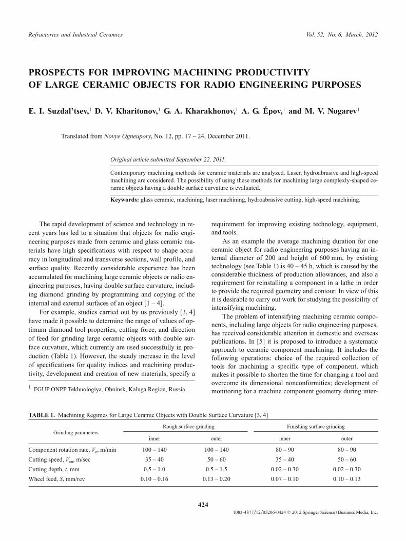
TABLE 1. Machining Regimes for Large Ceramic Objects with Double Surface Curvature [3, 4]
Grinding parameters
Rough surface grinding Finishing surface grinding
inner outer inner outer
Component rotation rate, Vc, m/min 100 – 140 100 – 140 80 – 90 80 – 90
Cutting speed, Vcu, m/sec 35 – 40 50 – 60 35 – 40 50 – 60
Cutting depth, t, mm 0.5 – 1.0 0.5 – 1.5 0.02 – 0.30 0.02 – 0.30
Wheel feed, S, mm/rev 0.10 – 0.16 0.13 – 0.20 0.07 – 0.10 0.10 – 0.13

nal and external machining with the aim of considerably re-
ducing the number of removals (installations) of a compo-
nent from a lathe. The measures proposed are of mainly of an
organizational nature and do not resolve the problem of ac-
celerating grinding.
There is specific interest in using ultrasonic vibration
(USV) for intensifying grinding, proposed in [6, 7]. Accord-
ing to data of this work, grinding with application of USV is
intensified due to complex processes that occur in the cutting
area. It is well known that material breakage with abrasive
treatment occurs as a result of the occurrence of micro- and
macrocracks, propagating to some depth. By intersecting
they create a weakened layer, easily removed with repeated
action of the grain of a wheel. Ultrasound, loosening
microcracks, accelerates material dispersion. In view of this
there is an increase in penetration of lubricating and cooling
liquids (LCL), and there is an improvement in slurry removal
from the machining area. Presence of a radial USV compo-
nent leads to an increase in the length of path travelled by
abrasive grains, and an increase in grain turning angle. Due
to the normal component of USV an increase is provided in
the overall number of active grains. Grains acquire a devel-
oped microrelief with a considerable number of elementary
cutting edges. The cutting force and temperature are reduced.
In order to implement this method the authors of [7] pro-
posed fitting the end of a grinding spindle of a lathe with a
small ultrasonic head, which was realized by them in stan-
dard flat grinding machines. Flat specimens were machined,
rigidly fastened to the surface of the removable table. Use of
this method for machining ceramic components, having dou-
ble surface curvature, which as a rule during grinding does
have a rigidly fixed wall, may only lead to additional wall vi-
brations of a machined billet, and as a consequence to loss of
machining accuracy.
Development of laser technology has made it possible to
consider the potential of using laser radiation for removing a
production allowance from curvilinear ceramic surfaces [8],
including from objects with double surface curvature [9].
In [9] the outer and inner surface of a billet of glass ce-
ramic material was machined in two stages: in the first stage
the main allowance (~2.5 mm) it is removed in one to five
passes by evaporation of glass ceramic under the action of
powerful laser radiation (yttrium-aluminum garnet laser with
neodymium (ND-YAG) with power up to 2000 W with a
wavelength of 1.06 mm, and in the second stage the remain-
ing allowance (~0.05 mm) is removed by finishing grinding
using diamond wheels. Here, as the authors in [9] confirm,
introduction of this method makes it possible to reduce by a
factor of two the cost of machining components compared
with standard diamond tool grinding methods. In addition, in
[9] it is noted that after laser treatment at the surface of a
shell there is formation of a layer about 0.05 mm thick of
amorphous glassy (fuzed) material, enriched with Al, Mg,
and Ti, compared with the original materials which is re-
moved by grinding in the concluding machining stage. In ad-
dition, data have been provided for the effect of laser treat-
ment itself (without final diamond grinding) on glass ce-
ramic dielectric properties. It was noted that laser machining,
used in manufacturing objects for radio engineering pur-
poses, does not have an unfavorable effect on the dielectric
properties of glass ceramic.
In order to verify the applicability of the methods indi-
cated above for machining objects of glass ceramic OTM
357-0 an experiment was carried out for removal of material
from the surface of a disk of this material. An ytterbium fiber
device YLR-200-3M-WC was used with a power of 250 W
and with a wavelength of 1.06 mm. The laser beam move-
ment rate (scanning rate) was measured in the range
20 – 1300 m/sec. The depth of material removal with one
pass of the beam in relation to its movement is presented in
Fig. 1. It follows from the data presented that the slower the
scanning rate for a specimen surface, the higher it its thermal
effect, and consequently a greater depth of material removal.
Whereas with a rate of 200 m/sec it is possible to achieve
material removal to a depth of 0.1 mm, with an increase in
rate to 700 – 800 m/sec there is reduction in depth of re-
moval to 0.01 mm, and a further increase in rate leads to al-
most total absence of this.
A dependence presented in Fig. 1 makes it possible to
suggest that by varying such values as laser scanning rate, la-
ser head movement rate (analog of feed rate), and rate of
component rotation, it is possible to achieve the required ma-
terial removal over the surface of a component. However, it
is necessary to consider that the greater removal of material,
the rougher is the machined surface obtained (Fig. 2).
In specimens of glass ceramic, machined area by area,
with different scanning rates (see Fig. 2) it is clearly seen that
the slower the laser beam passage rate, the greater is surface
defectiveness. With machining at a rate of 200 and 300 m/sec
coarse droplets of fuzed glass are seen at it. This leads to a
requirement of further machining of a fuzed surface by tradi-
tional diamond grinding technology, as has been proposed
in [9].
Thus, use of laser machining methods for objects of glass
ceramic materials is promising in the rough machining
stages, when a considerable part of the production allowance
is removed.
Prospects for Improving Machining Productivity of Large Ceramic Objects 425
Fig. 1. Dependence of material removal depth on laser beam scan-
ning rate.

Another promising method for machining relates to
hydroabrasive cutting (HAC), which recently has achieved
popularity in various branches of industry, including aero-
space. The principle of hydroabrasive cutting is simple and
involves the fact that water with an abrasive powder (often
agate powder is used for this purpose) under a very consider-
able pressure (more than 400 MPa) through a cutter (jet)
head, having a nozzle diameter of 0.5 – 0.8 mm, is fed to the
surface of material being machined. The nozzle diameter
provides preparation of a cutting width of 1 – 3 mm and a
surface roughness Ra = 0.5 – 1.5 �m. An HAC device is
equipped with systems with numerical programmed control
(CNC) and this makes it possible to carry out shaped cutting
by a prescribed program (Fig. 3). Here the main distinguish-
ing feature of HAC technology is absence of a thermal effect
on a machined component, which makes it possible to pre-
pare objects with a minimum defective layer
In addition, the good quality of cut surfaces and absence
of spalling at the inlet and outlet of the abrasive hydraulic
suspension jet should be noted. This is indicated by photo-
graphs of sections of ceramic specimens of different materi-
als presented in Fig. 3. Consequently, HAC has a number of
considerable advantages compared with traditional cutting of
ceramic materials by diamond wheels. Data are presented in
Table 2 for cutting rate of typical materials by existing tech-
nology, proceeding from operating standards and with use of
HAC technology.
It may be concluded by analyzing Table 2 and Fig. 3 that
currently for ceramic materials there is no more economic
cutting method as an alternative to HAC. In addition, this
method is irreplaceable for the production of flat ceramic
components of complex shape, since it makes it possible to
prepare round, shaped billets, and billets with through holes.
The question of use of this method for machining compo-
nents having a body of rotation of double surface curvature
remains open. However, it may be suggested that knowing
the rate for broaching holes in each specific material, by reg-
ulating the billet rotation rate and movement of the head with
nozzles, machining of an outer surface of a billet is entirely
possible. Implementation of the HAC method for machining
the inner surface will be difficult due to the impossibility of
placing a cutting head within the cavity of an object being
machined.
In spite of the visible, at first sight, advantage of using
such methods as laser evaporation and hydroabrasive cutting
for machining large ceramic, the high price of equipment for
their implementation compels setting aside into the future
work on these methods. In view of this it is desirable to carry
out work for optimizing existing technology and moderniza-
tion of equipment currently available.
As noted above, previously we have established that op-
timum production regimes for machining large ceramic bil-
lets, having double surface curvature (see Table 1). At the
same time, the regimes described above do not provided the
maximum machine productivity. This is mainly caused by
the fact that the support of a turning machine is connected
with a kinetic movement mechanism of the machine, which
provides movement of a grinding head (installed on a sup-
port) along the surface of an object being machined only
with a constant prescribed rate S (mm/rev). In the majority of
cases the configuration of ceramic objects for radio engineer-
ing purposes is a hollow cone, within which the diameter
426 E. I. Suzdal’tsev et al.
Fig. 2. Effect of laser beam movement rate (indicated over specimens,
m/sec) on glass ceramic OTM 357-O specimen surface quality.
TABLE 2. Comparative Cutting Characteristics of Different Ceramic materials
MaterialMaterial
thickness, mm
Traditional cutting,
cutting speed, mm/min
Hydroabrasive cutting
cutting speed, mm/minbreakthrough time for hole
with diameter 1 – 1.5 mm, sec
Glass ceramic OTM 357 18 20 – 30 100 25
Quartz ceramic 18 30 – 40 120 15
SiC 10 10 – 15 8 40
Al2O3 10 15 – 20 5 30

changes over the height (from 400 mm to a radius of curva-
ture in the nose section of 5 – 10 mm), and correspondingly
there are many changes in the volume of material removed
for equal intervals of time, which may be considered by the
following equation:
Q = �dtSnc, (1)
where Q is productivity, mm3/min; d is billet diameter, mm; t
is cutting depth, mm; S is wheel feed, mm/rev; nc
is compo-
nent rotations, rpm.
Thus, during machining of these components there is
nonuniform material removal over an object height. For ex-
ample, in machining large billets (with a base diameter of
400 mm) with the grinding parameters: S = 0.1 mm/rev,
t = 0.5 mm, n = 100 rpm, we have material removal in the
skirt area (diameter 400 mm) in an amount of 6.3 cm3/min,
and in the nose area (with a billet diameter of 50 mm) this
value is reduced to 0.8 cm3/min. This difference in material
removal can only lead to occurrence of gradients of load ap-
plied to the body of a billet, and in fact they will be at a max-
imum in the skirt part of a component.
Proceeding from this and considering that a billet under-
goes application of maximum loads in the skirt area without
breaking, it is possible to increase the productivity of turning
machines due to providing uniform material removal over
the surface of a billet. This may be achieved due to a gradual
increase in the amount of wheel feed or component rotation
rate.
Calculated data are presented in Fig. 4 for the amount of
wheel feed and component rotation in relation to a change in
billet diameter, which may be recommended for machining
ceramic objects. The basis of the calculation was Eq. (1), in
which as a constant the value of maximum material removal
in the skirt area was used. For uniform material removal over
the whole surface of a billet it is necessary to provide an
eightfold increase in the value of S or value of nc, which is
quite a complex task. This is surely indicated by data ob-
tained by us previously [3, 4] about the effect of feed rate and
cutting depth on cutting rate and wheel force (Fig. 5). An in-
crease in feed rate above 0.3 mm/rev is undesirable since
there is a considerable increase in cutting force and wheel
pressure, which has a negative effect on machined surface
quality. An increase in billet rotation rate to a value above
400 rpm due to quite considerable weight and weight imbal-
ance both for itself and for production equipment leads to
occurrence of forced vibrations also worsens machining
quality.
Thus, an increase in productivity during machining of
large ceramic billets is possible due to a compromise in-
crease in feed rate and component rotation. An example is
presented in Fig. 6 for implementing the proposed method
Prospects for Improving Machining Productivity of Large Ceramic Objects 427
Fig. 3. Examples of implementing hydroabrasive cutting for plates of different ceramic materials.

for a billet recently machined with a height of 1000 and base
diameter 320 mm. Initially an increase in productivity was
achieved only as a result of a gradual increase in feed rate.
Then on S reaching a value of 0.27 mm/rev there was a grad-
ual increase in component rotation rate to 240 rpm. No rec-
ommended properties are exceeded, but productivity in-
creases considerably. An estimate of the increase in produc-
tivity is possible by calculating the time required fro machin-
ing the whole surface of a component for one pass:
T = L/(Snc), (2)
where T in time, min; L is billet length, mm; S wheel feed,
mm/rev; nc
is component rotations, rpm.
Calculation by Eq. (2) taking account of data in Fig. 6
showed that only due to a gradual increase in wheel feed rate
and component rotation is it possible to shorten the duration
of one pass by 30 – 35% (from 100 to 65 – 70 min). In spite
of such a marked effect, this implementation is only possible
with use of CNC machines when knowing the size of a com-
ponent and the maximum permissible material removal, a
control program is developed that also controls the drives.
In the case of using of using copying lathes, undoubtedly
there is considerable help from using a device proposed by
us in [10], consisting of a traditional lathe with a copying
system and a pressure sensor placed on the grinding head,
connected with an analytical device, controlled in turn by the
lathe drive (drives for support feed and object rotation). Here
the support of the turning lathe is fitted with its own separate
from lathe movement mechanism kinematics, which makes it
possible to change support movement rate, and consequently
the grinding head along an object surface.
Installation of a pressure sensor on the grinding head
makes it possible to monitor the load applied a machine com-
ponent during the whole machining process. An analytical
device compares the signal from the pressure sensor with the
value applied to it, which is determined by calculation and
depends on the material, machined component wall thickness
and dimensions, and it feeds a command to the support drive
mechanism (or the object rotation drive) providing move-
ment of the grinding head along an object surface at a con-
stantly prescribed pressure on the machined object wall. The
scheme proposed makes it possible to shorten the number
grinding head passes over an object surface, and the overall
duration of machining by approximately 30 – 35%.
In spite of such a marked effect, productivity may be in-
creased even more. This becomes possible with use of
high-speed machining methods (high-speed cutting), which
recently have been used extensively in machining various
objects of ferrous and nonferrous metals [11 – 14]. The basis
of high-speed machining theory is the fact that in some nar-
row cutting rate range an increase leads to a reduction in cut-
ting force. This is represented more clearly by Solomon
curves (Fig. 7) obtained over 30 years of the last century by
Carl Solomon, who established that the cutting temperature
does not depend uniformly on cutting rate, but has a specific
extreme nature. This is caused primarily by the fact that in
small cutting cross sections in this range the main mass of
428 E. I. Suzdal’tsev et al.
Fig. 4. Calculated data for the dependence of feed rate nd and com-
ponent rotation rate S on billet diameter for providing Q = const.
Fig. 5. Dependence of cutting force Py (a) and wheel pressing � (b )
with different feed rates (shown on the curves, mm/rev) on cutting
depth t.
Fig. 6. Recommended feed rate parameters (1 ) and component ro-
tation rate (2 ) on billet length with the condition Q = const; 3) com-
ponent contour.
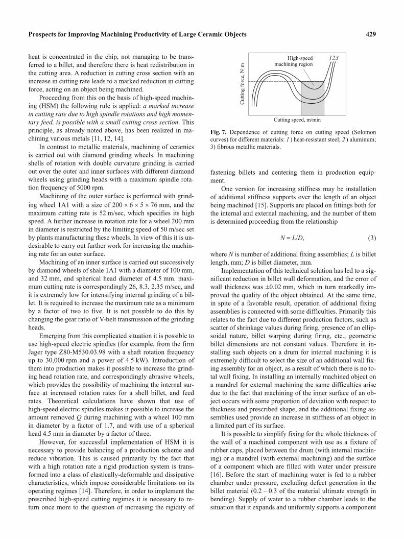
heat is concentrated in the chip, not managing to be trans-
ferred to a billet, and therefore there is heat redistribution in
the cutting area. A reduction in cutting cross section with an
increase in cutting rate leads to a marked reduction in cutting
force, acting on an object being machined.
Proceeding from this on the basis of high-speed machin-
ing (HSM) the following rule is applied: a marked increase
in cutting rate due to high spindle rotations and high momen-
tary feed, is possible with a small cutting cross section. This
principle, as already noted above, has been realized in ma-
chining various metals [11, 12, 14].
In contrast to metallic materials, machining of ceramics
is carried out with diamond grinding wheels. In machining
shells of rotation with double curvature grinding is carried
out over the outer and inner surfaces with different diamond
wheels using grinding heads with a maximum spindle rota-
tion frequency of 5000 rpm.
Machining of the outer surface is performed with grind-
ing wheel 1A1 with a size of 200 � 6 � 5 � 76 mm, and the
maximum cutting rate is 52 m/sec, which specifies its high
speed. A further increase in rotation rate for a wheel 200 mm
in diameter is restricted by the limiting speed of 50 m/sec set
by plants manufacturing these wheels. In view of this it is un-
desirable to carry out further work for increasing the machin-
ing rate for an outer surface.
Machining of an inner surface is carried out successively
by diamond wheels of shale 1A1 with a diameter of 100 mm,
and 32 mm, and spherical head diameter of 4.5 mm. maxi-
mum cutting rate is correspondingly 26, 8.3, 2.35 m/sec, and
it is extremely low for intensifying internal grinding of a bil-
let. It is required to increase the maximum rate as a minimum
by a factor of two to five. It is not possible to do this by
changing the gear ratio of V-belt transmission of the grinding
heads.
Emerging from this complicated situation it is possible to
use high-speed electric spindles (for example, from the firm
Jager type Z80-M530.03.98 with a shaft rotation frequency
up to 30,000 rpm and a power of 4.5 kW). Introduction of
them into production makes it possible to increase the grind-
ing head rotation rate, and correspondingly abrasive wheels,
which provides the possibility of machining the internal sur-
face at increased rotation rates for a shell billet, and feed
rates. Theoretical calculations have shown that use of
high-speed electric spindles makes it possible to increase the
amount removed Q during machining with a wheel 100 mm
in diameter by a factor of 1.7, and with use of a spherical
head 4.5 mm in diameter by a factor of three.
However, for successful implementation of HSM it is
necessary to provide balancing of a production scheme and
reduce vibration. This is caused primarily by the fact that
with a high rotation rate a rigid production system is trans-
formed into a class of elastically-deformable and dissipative
characteristics, which impose considerable limitations on its
operating regimes [14]. Therefore, in order to implement the
prescribed high-speed cutting regimes it is necessary to re-
turn once more to the question of increasing the rigidity of
fastening billets and centering them in production equip-
ment.
One version for increasing stiffness may be installation
of additional stiffness supports over the length of an object
being machined [15]. Supports are placed on fittings both for
the internal and external machining, and the number of them
is determined proceeding from the relationship
N = L/D, (3)
where N is number of additional fixing assemblies; L is billet
length, mm; D is billet diameter, mm.
Implementation of this technical solution has led to a sig-
nificant reduction in billet wall deformation, and the error of
wall thickness was ±0.02 mm, which in turn markedly im-
proved the quality of the object obtained. At the same time,
in spite of a favorable result, operation of additional fixing
assemblies is connected with some difficulties. Primarily this
relates to the fact due to different production factors, such as
scatter of shrinkage values during firing, presence of an ellip-
soidal nature, billet warping during firing, etc., geometric
billet dimensions are not constant values. Therefore in in-
stalling such objects on a drum for internal machining it is
extremely difficult to select the size of an additional wall fix-
ing assembly for an object, as a result of which there is no to-
tal wall fixing. In installing an internally machined object on
a mandrel for external machining the same difficulties arise
due to the fact that machining of the inner surface of an ob-
ject occurs with some proportion of deviation with respect to
thickness and prescribed shape, and the additional fixing as-
semblies used provide an increase in stiffness of an object in
a limited part of its surface.
It is possible to simplify fixing for the whole thickness of
the wall of a machined component with use as a fixture of
rubber caps, placed between the drum (with internal machin-
ing) or a mandrel (with external machining) and the surface
of a component which are filled with water under pressure
[16]. Before the start of machining water is fed to a rubber
chamber under pressure, excluding defect generation in the
billet material (0.2 – 0.3 of the material ultimate strength in
bending). Supply of water to a rubber chamber leads to the
situation that it expands and uniformly supports a component
Prospects for Improving Machining Productivity of Large Ceramic Objects 429
Fig. 7. Dependence of cutting force on cutting speed (Solomon
curves) for different materials: 1 ) heat-resistant steel; 2 ) aluminum;
3) fibrous metallic materials.

being machined, as a result of which there is a significant re-
duction in component wall deformation, there is pressure re-
distribution along the grind head on the whole surface of a
component being machined, which in turn facilitates compo-
nent machining and markedly improves quality.
Thus, it is possible to dare to assert that HSM is the most
promising direction in the field of machining ceramic materi-
als, and carrying out work in this area will make it possible to
increase productivity considerably during machining of large
ceramic objects with improvement in surface quality.
REFERENCES
1. E. A. Vorob’ev, “Machining of radioparent sharp-ended air-
borne equipment radomes,” Instrument, No. 10, 22 – 23 (1998).
2. A. G. Épov, A. G. Ustinov, G. A. Kharakhonov, et al., “Features
of internal machining for complexly shaped objects RPO-50,”
Proc. XVII Sci.-Tech. Conf. “Construction and technology for
preparing objects from non-metallic materials,” Obninsk, Oct.
(2004).
3. E. I. Suzdal’tsev, A. G. Épov, A. S. Khamitsaev, et al., “Study of
the effect of machining regimes for glass ceramic objects in the
system: lathe – object – tool – scheme,” Ogneupory. Tekhn.
Keram., No. 7, 23 – 31 (2003).
4. Yu. E. Pivinskii and E. I. Suzdal’tsev, (Yu. E. Pivinskii, editor),
Quartz ceramics and Refractories. Vol. 1. Theoretical Bases
and Production Processes: Reference ed. [in Russian],
Teploenergetik, Moscow (2008).
5. J. McGovern, Ceramic Radome Machining. Tooling Applica-
tions, Navy SBIR, No. 1 (2008). Topic N08 – 011 (http://
www.navysbir.com/n08_1/ N081-011.htm).
6. G. N. Zaitsev, N. V. Nikitov, and I. Kh. Buturovich, “Efficiency
of plane ultrasonic grinding of ceramic with a diamond toll,”
Steklo Keram., No. 4, 17 – 18 (1980).
7. G. N. Zaitsev and V. A. Ivanov, “Ultrasonic diamond grinding of
ceramic plates,” Steklo Keram., No. 1, 21 – 22 (1987).
8. V. M. Kirillov, Inventor’s Cert. 1202171. Laser machining
method for curvilinear surfaces and device for accomplishing it,
Claim 03.28.84, Publ. 02.10.00.
9. K. Kirby, D. Engin, T. Jankiewicz, and J. W. Barber, US Patent
5665134, Lazer machining of glass ceramic materials. 09.09.97.
10. E. I. Suzdal’tsev,, D. V. Kharitonov, G. K. Rogov, et al., RF Pat-
ent 2312764 Device for machining large complexly shaped ce-
ramic objects, Claim 04.03.06, Publ. 12.20.07, Byul. No. 35.
11. K. Wittington and V. Vlasov, “High-speed machining,” SAPR i
Grafika, No. 11, 107 – 113 (2002).
12. A. A. Tarasov, V. N. Krutov, V. A. Treyal’, et al., “High-speed
machining — a tool for increasing production efficiency,” In-
strument Tekhnol, N0. 29 (23), 112 – 114 (2010).
13. R. Pasko, “High-speed machining (HSM) — the effect way of
modern cutting,” Internat. Workshop CA Systems and Technol.,
No. 3 / 4, 72 – 79 (2002).
14. V. K. Sheleg, A. F. Prisevok, and P. N. Klavsut’, “Production fa-
cilities for accuracy parameters and quality of complexly
shaped components during high-speed multicoordinate machin-
ing,” Vestnik BNTU, No. 5, 22031 (2009).
15. E. I. Suzdal’tsev,, D. V. Kharitonov, and A. S. Khamitsaev, RF
Patent 2258596, Device for machining large complexly shaped
ceramic objects, Claim 11.24.03, Publ. 08.20.05, Byul. No. 23.
16. E. I. Suzdal’tsev,, D. V. Kharitonov, A. V. Dimtriev, et al, RF
Patent 23134338 Device for machining large complexly shaped
ceramic objects, Claim 02.03.06, Publ. 12.27.07, Byul. No. 36.
430 E. I. Suzdal’tsev et al.