protection and control sepam range sepam 2000...
TRANSCRIPT

Protectionand control
Sepam rangeSepam 2000Motor

2 Motor
page
presentation 2
selection table 3
metering 4
protection 6
control and monitoring 8
functional and connection schemes 11
other connection schemes 17
examples of connections 19
communication 20
characteristics 21
installation 22
ordering information 24
Presentation
Contents
Motor protection and control consists of performingthe metering, protection, control and monitoringfunctions required for operation.
Sepam 2000 provides all these functions globally.All the equipment and mechanisms that are generallyfound in a MV cubicle control cabinet are replacedby a single device which performs:c protection,c metering,c control and monitoring using protection functionsand logic inputs to activate the trip outputs, closingoutputs, etc. and annunciation.
Advantagesc Indication of phase and earth fault current values at the time of breaking providesthe operator with useful assistance in determining the causes and seriousnessof the fault,c The high level of electromagnetic compatibility (EMC) makes it possible to useadvanced digital technology functions in electrical substations, without the needfor any particular precautions,c Sepam 2000's continuous self-testing sets the device in a predetermined fail-safe position whenever a failure occurs, thereby preventing random operation,c Terminals that are individually disconnectable while energized allow easymaintenance, The optional communication function can be used for remote setting, remotemetering, remote annunciation and remote control via a 2 wire link with a remotecontrol and monotoring system for centralised operations.c Setting and testing are extremely simple:v the settings may be made on the front panel (serial link):- one by one, using the TSM2001 pocket terminal, or the SFT2801 PC softwareprogram,- all at once using the SFT2821 PC software program (downloading),v a direct readout is given for primary current and voltage and for the meteringfunction, simple testing by injection guarantees the coherency of all settings.c Each Sepam 2000 is designed to meet all the application needs and includes allthe necessary functions ready for use (protection functions, metering, control logicand communication).The control logic may be adapted to most usuals schemes by a simpleparametring. This allows a better safety and optimization of wiring.
The wide setting ranges provide for the most widely varied cases.Installation in the switchboard is simplified:c just one device to install, the Sepam 2000. It comes in two modelswith different widths:v standard S36,v compact S26 (for certain types).c cabling is limited to:v standard 1A or 5A current transformers or linear CSP sensors (Rogowski coilprinciple),v voltage transformers,v temperature probes (RTDs),v control and annunciation units (start/stop pushbutton, device position, etc),v actuators (trip and closing coils).
Customization (1)
Standard control and monitoring carried out in Sepam 2000's internal PLC can becustomized. The number of inputs and outputs can be increased by addingextension boards (please contact us for further information).
Sepam 2000Compact S26.
Sepam 2000Standard S36.
(1) Please refer to documentSepam 2000 customized application.

3Motor
Selection table
functions ANSI Sepam types (1)
code M02 M03 M04 M05 M06 M07 M08 M09 M11 M14 M15 M16M20 M21 M22 M23
protectionthermal overload 49 1 1 1 1 1 1 1 1 1 1 1 1phase overcurrent 50/51 2 2 2 2 2 2 2 2 2 2 2 2earth fault (sensitive E/F) 50N/51N(G) 2 2 2 2 2 2 2 2 2 2 2 2negative sequence/unbalance 46 1 1 1 1 1 1 1 1 1 1 1 1locked rotor/excessive starting time 48/51LR 1 1 1 1 1 1 1 1 1 1 1 1phase undercurrent 37 1 1 1 1 1 1 1 1 1 1 1 1starts per hour 66 1 1 1 1 1 1 1 1 1 1 1 1positive sequence undervoltage 27D 2 2 2 2 2 2 2 2 2 2direction of rotation 47 1 1 1 1 1 1 1 1 1 1directional earth fault 67N 1 1 1 1reverse real power 32P 1 1 1reactive overpower 32Q/40 1 1 1temperature set points 38/49T 6 6 6 6 6 6 6
12 12 12 12motor differential 87M 1 1 1 1meteringphase currents (I1, I2, I3) c c c c c c c c c c c cpeak demand phase currents (I1, I2, I3) c c c c c c c c c c c cvoltages (U21, U32, U13, V1, V2, V3) c c c c c c c c c creal / reactive power (P, Q) c c c c c c c c c cpeak demand real / reactive power c c c c c c c c c cpower factor c c c c c c c c c cfrequency c c c c c c c c c caccumulated real / reactive energy (±Wh, ±VArh) c c c c c c c c c ctripping currents (I1, I2, I3, Io) c c c c c c c c c c c ctrue rms current c c c c c c c c c c c cdisturbance recording c c c c c c c c c c c cthermal capacity used c c c c c c c c c c c cstart inhibit time delay / c c c c c c c c c c c cnumber of starts before inhibitiontemperature c c c c c c cphase rotation c c c c c c c c c cunbalance ratio / unbalance current c c c c c c c c c c c cstarting time and current c c c c c c c c c c c cresidual current c c c c c c c c c c c cresidual voltage c c c ccumulative breaking current c c c c c c c c c c c cand number of breaksdifferential current and through current c c c ccontrol and monitoringopen / close c c c c c c c c c c c clockout relay 86 c c c c c c c c c c c cinhibit closing 69 c c c c c c c c c c c cannunciation 30 c c c c c c c c c c c cload shedding c c c c c c c c c c c crestart c c c c c c c c c clogic discrimination 68 c c c c c c c c c c c ctrip circuit supervision 74 c c c c c c c c c c c cdetection of plugged 74 c c c c c c c c c c c cconnectors (DPC)operation counter c c c c c c c c c c c crunning hours counter c c c c c c c c c c c cphase fault trip counter c c c c c c c c c c c cdisturb. recording triggering c c c c c c c c c c c cSepam modelsstandard S36 YR XR XR ZR LR LS LS SR SR LS XR SR
SS SS SS SScompact S26 LX LT LT LS (2) LTnumber of standard ESTOR boards 1 1 1 1 1 1 1 1 1 1 1 1
Sepam 2000 motors
The figures in the columns represent the number of similar protection devices.Example: for phase overcurrent protection, “2” means 2 separate phase overcurrent protection devices.(1) for motor transformers, please consult us.(2) except for M20.

4 Motor
Metering
Sepam 2000 is an accurate metering device.It gives a direct readout of values, togetherwith the related units, A, V, W...All the values needed for operation and usedfor commissioning are available locally and inthe control room.
Measurements needed for operation
CurrentsMeasurement of the current for each of the 3 phases of the circuit.
Peak demand currentsMeasurement of the greatest average current value on the 3 phases.The average current measurement is computed periodically (adjustable period: 5,10, 15, 30 or 60 minutes).The “clear” button is pressed for zero reset.
VoltagesMeasurement of the circuit phase-to-phase and phase-to-neutral voltages.
Real / reactive powerMeasurement of the real and reactive power, with the sign, in balancedand unbalanced 3-phase networks.
Peak demand real / reactive powerMeasurement of the greatest average real power (and reactive power) value,used to find the power absorbed during peak load periods. The average valueis computed periodically (adjustable period: 5, 10, 15, 30 or 60 minutes).The “clear” button is pressed for zero reset.
Power factor (p.f.)Measurement of the power factor, with the sign and type (capacitive or inductive),of the power absorbed.
FrequencyMeasurement of frequency (based on positive sequence voltage or the U21 voltageinput).
Accumulated real / reactive energyThe alphanumerical display unit shows the 4 accumulated real / reactive energyvalues:c real energy consumed,c reverse real energy,c reactive energy consumed,c reverse reactive energy.These values are saved in the event of a power failure.
Tripping currentsMeasurements of the 3 phase currents and the residual current that were storedat the time that Sepam 2000 gave the tripping order. Used to find the fault current(fault analysis) and assess the level of wear of the breaker(maintenance assistance).The "clear" button is pressed for zero reset.
True rms currentMeasurement of the rms value of phase 1 current up to 4 In, taking into account:c fundamental,c harmonics up to rank 21.
Disturbance recordingRecording of electrical signals and logical information before and after a faultrecorder triggering order is given.
Thermal capacity usedMeasurement of the relative thermal capacity used (with respect to the nominalthermal capacity) on account of the load.
Start inhibit time delay / number of starts before inhibitionAccording to the state of the "starts per hour" protection function, indication of:c the remaining time during which starting is inhibited,c the number of starts authorized before inhibition of starting.
TemperatureTemperature measurement in °C for each RTD.
Measurements accessed on the front panel of Sepam 2000(serial link and/or display) and via the communicationsystem.

5Motor
functions ranges accuracy (4)
ammeter (1) 0 to 24 In ±0.5%
peak demand current (1) 0 to 24 In ±0.5%
voltmeter (1) 0 to 1.5 Un ±0.5%
wattmeter (1) 0 to 999 MW ±1%
varmeter (1) 0 to 999 MVAr ±1%
peak demand real power (1) 0 to 999 MW ±1%
peak demand reactive power (1) 0 to 999 MVAr ±1%
power factor (1) (3) -1 to +1 0.01
frequency meter (1) 45 to 65 Hz ±0.02 Hz
accumulated real energy (1) 0 to 280.106 MWh ±1%
accumulated reactive energy (1) 0 to 280.106
MVArh ±1%
tripping currents (1) phase: 0 to 24 In ±5%
earth: 0 to 10 Ino ±5%
true rms current (2) 0 to 4 In ±1%up to rank 21
disturbance recording (5) record 86 periods 12 samplesduration per period
time before 1 to 85 periodstriggeringevent
thermal capacity used (6) 0 to 999% ±2%
temperature (1) -50° to 250°C ±1°Cphase rotation (2) anticlockwise, clockwise
unbalance ratio (unbalance current) (2) 0 to 100% of Ib ±5%
starting time (2) 0 to 999 s ±5%
starting current (2) 0 to 24 In ±5%
residual current (6) 0 to 10 Ino ±5%
residual voltage (6) 0 to 1.5 Un ±5%
cumulative breaking current (6) 0 to 9999 (kA)2 +10%
number of breaks (6) 0 to 99999
differential current and through current (2) 0 to 24 In ±5%
Characteristics
(1) measurement accessed on the front panel of Sepam 2000 (display and serial link) and viathe communication system.
(2) measurement accessed on the front panel of Sepam 2000 (serial link).(3) capacitive or inductive(4) typical accuracy with nominal values according to IEC 60255-6.(5) transfer of records to the front panel of Sepam 2000 using the SFT2801 software program
and via Jbus/Modbus communication.(6) measurement accessed on front panel of Sepam 2000 (serial link) and via the
communication system.
Reminder:Rated current In, basis current Ib, rated voltage Un and current Ino are general parametersthat are set at the time of Sepam 2000 commissioning.In is the current sensor rated current (CT rating).Ib is the current which corresponds to the motor power rating, adjustable from 0.4 to 1.3 In.Ino is the core balance CT current rating.Un is the phase-to-phase voltage of the voltage sensor primary windings.
Measurements usedfor commissioningand maintenance
Phase rotationConnection check, which gives the direction of phaserotation: “anticlockwise” or “clockwise”.
Unbalance ratio / unbalance currentAssistance in determining settings by givingthe unbalance ratio measured as a percentage(negative sequence / absorbed current).
Starting time and currentUsed to check the starting time and current to adjustovercurrent protection setting.
Residual current / residual voltageUsed to check the current and voltage sensorconnections by giving the measurement of:c the residual current used for the earth faultprotection function,c the residual voltage used for the directional earthfault protection function.
Cumulative breaking currentand number of breaksUsed for breaking device maintenance.
Differential current and through currentUsed to check the current sensor connections.Used to determine the cause of tripping.
Example of the processing of a disturbance recording recordusing the SFT 2826 PC software program.

6 Motor
Protection
Thermal overload (ANSI 49) F431*Protection of equipment against thermal damagecaused by overloads. Thermal overload is calculatedaccording to a mathematical model, with 2 timeconstants (T1 and T2), taking into account the effectof negative sequence current by meansof an adjustable weighting coefficient.The function comprises:c an adjustable alarm setting,c an adjustable trip setting.
Phase overcurrent (ANSI 50/51) F011, F012*Three-phase equipment protection againstphase-to-phase (short-circuit) faults.The following types of time delay settings areavailable: definite, standard inverse, very inverse,extremely inverse or ultra inverse.Recommendations:c set higher than starting current,c instantaneous operation if the equipmentis controlled by a circuit breaker or contactor only.c time delayed operation if the equipmentis controlled by a contactor-fuse combination so thatthe fuse blows before the contactor when the faultcurrent is greater than the contactor's breakingcapacity.
Earth fault (ANSI 50N/51N or 50G/51G) F081, F082*Connection and equipment earth fault protection.The following types of time delay settings are available:definite, standard inverse, very inverse, extremelyinverse or ultra inverse.
When earth fault current is detected by taking thesum of the 3 phase CTs, a harmonic 2 restraint isused to do away with transformer closing relatedtripping.
Recommendations:c connection to special-purpose CSH core balanceCT for greater sensitivity,c definite time operation.
Negative sequence / unbalance (ANSI 46) F451*Protection of equipment against overheating causedby an unbalanced power supply, phase inversion orphase break, and against low levels of overcurrentbetween 2 phases.Recommendation:c use IDMT curves.
Locked rotor / excessive starting time(ANSI 48/51LR) F441*Protection of motors that are liable to startwith overloads or insufficient supply voltageand/or that drive loads that are liable to becomelocked (e.g. crusher).Locked rotor protection function is only confirmedafter a time delay that corresponds to the normalstarting time.
Phase undercurrent (ANSI 37) F221*Pump protection against the consequences of primingloss. This protection detects delayed undercurrentcorresponding to motor no-load operation whichis typical of a loss of pump priming.
Starts per hour (ANSI 66) F421*Protection against overheating caused by too frequent starts.Checking of:c the number of starts per hour,c the number of consecutive warm starts (detected by the thermaloverload protection),c the number of consecutive cold starts.The protection inhibits motor energizing for a preset time period when thepermissible limits are reached.
Positive sequence undervoltage (ANSI 27D) F381, F382*Protection which prevents motor malfunctioning due to insufficient or unbalancedsupply voltage.
Direction of rotation (ANSI 47) F381*Protection which prevents the changing of direction of motor rotation followinga power supply modification.
Directional earth fault (ANSI 67N) F501*Highly sensitive earth fault protection for motor feeders supplied by long cablescharacterized by high capacitive current.
Reverse real power (ANSI 32P)Protection of a synchronous motor against operation as a generator when drivenby its load.It is based on the "real overpower" F531* function.
Reactive overpower (ANSI 32Q/40) F541*Protection of a synchronous motor against field loss which causesoverconsumption of reactive power and leads to the loss of synchronism.
Temperature monitoring (RTDs) (ANSI 38/49T) F461...F466, F471...F476*Protection which detects abnormal overheating of motors (bearings and/orwindings) equipped with Pt 100 type platinum resistive temperature devices:c 1 alarm setting,c 1 tripping setting.The RTD cabling is continuously monitored.
Motor differential (ANSI 87M) F621*Fast, sensitive motor protection against internal faults due to damaged insulation.The protection is based on the principle of percentage differentials. It includesstarting current restraint to sustain stability in spite of its high level of sensitivity.
Current sensor sizingc The current sensors should be sized so as not to be saturated by the currentvalues which they are required to measure with accuracy (at least 5 In):c For differential protection:the current transformers should be of the 5P20 type.
The power rating must be chosen so that the wiring resistance (Rw) is less than therated load of the current transformer (VACT), i.e.:VACT > Rw . In2
In: CT rated current at the secondary of the CT.
* Fxxx function identification for protection setting.
7Motor
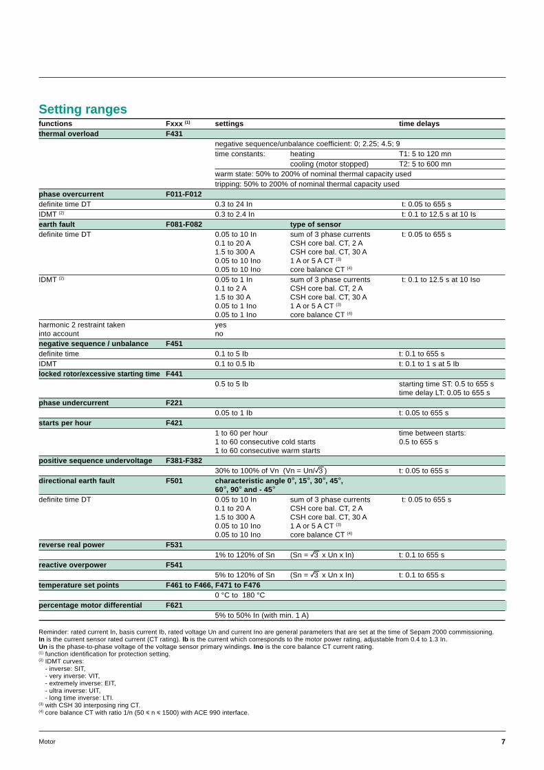
functions Fxxx (1) settings time delaysthermal overload F431
negative sequence/unbalance coefficient: 0; 2.25; 4.5; 9time constants: heating T1: 5 to 120 mn
cooling (motor stopped) T2: 5 to 600 mnwarm state: 50% to 200% of nominal thermal capacity usedtripping: 50% to 200% of nominal thermal capacity used
phase overcurrent F011-F012definite time DT 0.3 to 24 In t: 0.05 to 655 sIDMT (2) 0.3 to 2.4 In t: 0.1 to 12.5 s at 10 Isearth fault F081-F082 type of sensordefinite time DT 0.05 to 10 In sum of 3 phase currents t: 0.05 to 655 s
0.1 to 20 A CSH core bal. CT, 2 A1.5 to 300 A CSH core bal. CT, 30 A0.05 to 10 Ino 1 A or 5 A CT (3)
0.05 to 10 Ino core balance CT (4)
IDMT (2) 0.05 to 1 In sum of 3 phase currents t: 0.1 to 12.5 s at 10 Iso0.1 to 2 A CSH core bal. CT, 2 A1.5 to 30 A CSH core bal. CT, 30 A0.05 to 1 Ino 1 A or 5 A CT (3)
0.05 to 1 Ino core balance CT (4)
harmonic 2 restraint taken yesinto account nonegative sequence / unbalance F451definite time 0.1 to 5 Ib t: 0.1 to 655 sIDMT 0.1 to 0.5 Ib t: 0.1 to 1 s at 5 Iblocked rotor/excessive starting time F441
0.5 to 5 Ib starting time ST: 0.5 to 655 stime delay LT: 0.05 to 655 s
phase undercurrent F2210.05 to 1 Ib t: 0.05 to 655 s
starts per hour F4211 to 60 per hour time between starts:1 to 60 consecutive cold starts 0.5 to 655 s1 to 60 consecutive warm starts
positive sequence undervoltage F381-F38230% to 100% of Vn (Vn = Un/e) t: 0.05 to 655 s
directional earth fault F501 characteristic angle 0°, 15°, 30°, 45°,60°, 90° and - 45°
definite time DT 0.05 to 10 In sum of 3 phase currents t: 0.05 to 655 s0.1 to 20 A CSH core bal. CT, 2 A1.5 to 300 A CSH core bal. CT, 30 A0.05 to 10 Ino 1 A or 5 A CT (3)
0.05 to 10 Ino core balance CT (4)
reverse real power F5311% to 120% of Sn (Sn = e x Un x In) t: 0.1 to 655 s
reactive overpower F5415% to 120% of Sn (Sn = e x Un x In) t: 0.1 to 655 s
temperature set points F461 to F466, F471 to F4760 °C to 180 °C
percentage motor differential F6215% to 50% In (with min. 1 A)
Reminder: rated current In, basis current Ib, rated voltage Un and current Ino are general parameters that are set at the time of Sepam 2000 commissioning.In is the current sensor rated current (CT rating). Ib is the current which corresponds to the motor power rating, adjustable from 0.4 to 1.3 In.Un is the phase-to-phase voltage of the voltage sensor primary windings. Ino is the core balance CT current rating.(1) function identification for protection setting.(2) IDMT curves:
- inverse: SIT,- very inverse: VIT,- extremely inverse: EIT,- ultra inverse: UIT,- long time inverse: LTI.
(3) with CSH 30 interposing ring CT.(4) core balance CT with ratio 1/n (50 i n i 1500) with ACE 990 interface.
Setting ranges

8 Motor
Control and monitoring
Open / close controlUsed to control breaking devices equipedwith different types of opening and closing coils:c circuit breaker with shunt-trip or undervoltagerelease coil,c latching contactor with shunt-trip coil,c contactor with impulse or latched order control.
Parameter setting via the TSM 2001 pocket terminal,or PC softwares (SFT 2801 or SFT 2821), allows thelogic to be adapted to suit the equipment being used(by default, the logic is adapted for control of a circuitbreaker with a shunt-trip coil).
The opening order (via input I13) differs accordingto the programmed type of control:c normally open contact for shunt trip coil (circuitbreaker or contactor with latched order control),c normally closed contact for undervoltage releasecoil (circuit breaker or contactor with impulseor permanent order control).
Lockout relay (ANSI 86)Stores tripping orders (lockout) and requires useraction to be put back into operation (reset).
Inhibit closing (ANSI 69)Inhibits the closing of the circuit breaker or thecontactor according to operating conditions.
Annunciation (ANSI 30)Keeps the user informed by the display of messages.
Load sheddingCauses a shutdown as a result of an external orderor a drop in network supply voltage(except for M02, M05 and M20).
RestartStaggers motor restarts after a brief voltage dropso as to avoid overloading the network.
Logic discrimination (ANSI 68)Enables quick, selective tripping of the phaseovercurrent and earth fault protection relays, whetherdefinite time (DT) or IDMT (standard inverse SIT,very inverse VIT, extremely inverse EIT or ultrainverse UIT).The function triggers the transmission of a "blockinginput" signal whenever one of the protection settingsis exceeded. Blocking input signal transmission canbe used by the Sepam 2000 Logic discriminationfunction for substation, generator, transformer andbusbar connection applications.
Trip circuit supervision and discrepancy (ANSI 74)Detects tripping (by shunt-trip coil) circuit faults.Can be used when the Sepam 2000 and the tripping auxiliary power sources havethe same voltage rating.If the equipment contains an undervoltage release coil only, the tripping circuit isnot supervised since it is fail-safe.This function can also detect position information discrepancies (neither opennor closed or simultaneously open and closed) in the different control schemes.The connection of inputs I1, I2 and trip output O1 on the ESB board must berespected (see other connection schemes).
Detection of plugged connectors (ANSI 74)Indication on the display unit that one or more connectors are not pluggedin (the DPC terminals must be connected: see connection schemes).
Operation counter (1)
Counts the number of closing operations made by the breaking device, therebyfacilitating equipment maintenance.
Running hours counter (1)
Determines the time during which the breaking device (contactor or circuit breaker)is in the “in service-closed” position, i.e. the number of hours of operation(0 to 65535 hours).
Phase fault trip counter (1)
Counts the number of operations for which breaking performances were required,thereby facilitating equipment maintenance.
Disturbance recording triggeringTriggers recording of electrical signals and logical states by:c voluntary local or remote action,c instantaneous overcurrent, earth fault and motor differential protections,c protection tripping order.
(1) counter reading is via serial link on the front panel of Sepam 2000, and via Jbus/Modbuscommunication.
9Motor
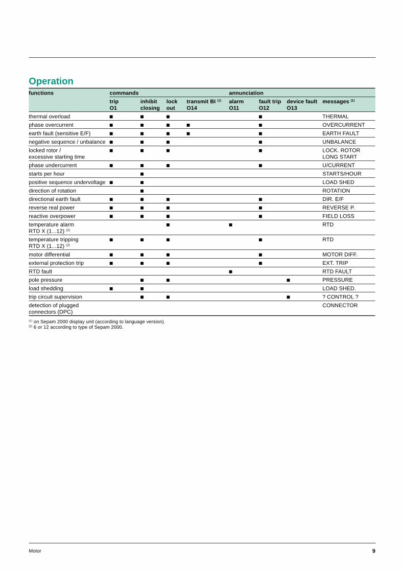
functions commands annunciation
trip inhibit lock transmit BI (1) alarm fault trip device fault messages (1)
O1 closing out O14 O11 O12 O13
thermal overload c c c c THERMAL
phase overcurrent c c c c c OVERCURRENT
earth fault (sensitive E/F) c c c c c EARTH FAULT
negative sequence / unbalance c c c c UNBALANCE
locked rotor / c c c c LOCK. ROTORexcessive starting time LONG START
phase undercurrent c c c c U/CURRENT
starts per hour c STARTS/HOUR
positive sequence undervoltage c c LOAD SHED
direction of rotation c ROTATION
directional earth fault c c c c DIR. E/F
reverse real power c c c c REVERSE P.
reactive overpower c c c c FIELD LOSS
temperature alarm c c RTDRTD X (1...12) (2)
temperature tripping c c c c RTDRTD X (1...12) (2)
motor differential c c c c MOTOR DIFF.
external protection trip c c c c EXT. TRIP
RTD fault c RTD FAULT
pole pressure c c c PRESSURE
load shedding c c LOAD SHED.
trip circuit supervision c c c ? CONTROL ?
detection of plugged CONNECTORconnectors (DPC)
Operation
(1) on Sepam 2000 display unit (according to language version).(2) 6 or 12 according to type of Sepam 2000.
10 Motor
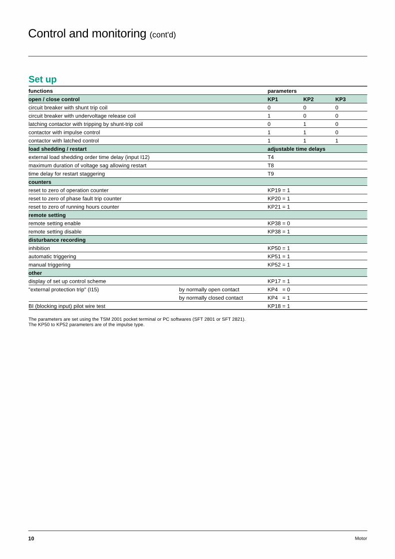
functions parameters
open / close control KP1 KP2 KP3
circuit breaker with shunt trip coil 0 0 0
circuit breaker with undervoltage release coil 1 0 0
latching contactor with tripping by shunt-trip coil 0 1 0
contactor with impulse control 1 1 0
contactor with latched control 1 1 1
load shedding / restart adjustable time delays
external load shedding order time delay (input I12) T4
maximum duration of voltage sag allowing restart T8
time delay for restart staggering T9
counters
reset to zero of operation counter KP19 = 1
reset to zero of phase fault trip counter KP20 = 1
reset to zero of running hours counter KP21 = 1
remote setting
remote setting enable KP38 = 0
remote setting disable KP38 = 1
disturbance recording
inhibition KP50 = 1
automatic triggering KP51 = 1
manual triggering KP52 = 1
other
display of set up control scheme KP17 = 1
"external protection trip" (I15) by normally open contact KP4 = 0
by normally closed contact KP4 = 1
BI (blocking input) pilot wire test KP18 = 1
The parameters are set using the TSM 2001 pocket terminal or PC softwares (SFT 2801 or SFT 2821).The KP50 to KP52 parameters are of the impulse type.
Set up
Control and monitoring (cont'd)

11Motor
.A……
.A
terminal numberfor compact (S26)Sepam 2000
terminal numberfor standard (S36)Sepam 2000
Functional and connection schemes
M02 type
(1)
14
52
63
ECM2B
L1
L2
L3
CE40 1B
1A 4
23
1
56
432
2A
30 A
DPC
2 A
ESB 5A
DPC
O2
O1
l2
l1
CDG
2120
19
1716
131211
5
10
1415
18
76
4
2
98
3
1
49505150N51N4651LR3766
M
2120
19
1716
131211
5
10
1415
18
76
4
2
98
3
1
6A
DPC
O11
l12
l11
O12
O13
O14
l13l14l15l16l17l18
ESTOR
1
4A
5A(1)
CSH
Standard S36YR or compact S26LXSepam 2000.
N.B.Refer to the "other connection schemes"section regarding other arrangements.DPC: detection of plugged connectors.CDG: watchdog.
c Correspondence between primaryand secondary connection (i.e.: P1, S1).
(1)

12 Motor
.A……
.A
terminal numberfor compact (S26)Sepam 2000
terminal numberfor standard (S36)Sepam 2000
Functional and connection schemes (cont'd)
M03, M04, M15 types
Standard S36XR or compact S26LTSepam 2000.
14
52
63
ECM2B
L1
L2
L3
CE40 1B
1A 4
23
1
56
432
2A
30 A
DPC
2 A
ESB 5A
DPC
O2
O1
l2
l1
CDG
2120
19
1716
131211
5
10
1415
18
76
4
2
98
3
1
M
2120
19
1716
131211
5
10
1415
18
76
4
2
98
3
1
6A
DPC
O11
l12
l11
O12
O13
O14
l13l14l15l16l17l18
ESTOR
5A(1)
4A 3U/Vo
56
4321
78
DPC
27D47
32P40
67NM03
49505150N51N4651LR3766
M04
1
3A(1)
4A(1)
CSH
N.B.Refer to the "other connection schemes"section regarding other arrangements.DPC: detection of plugged connectors.CDG: watchdog.
c Correspondence between primaryand secondary connection (i.e.: P1, S1).
(1)

13Motor
M05, M20 types
Standard S36ZR or compact S26LSSepam 2000 (M05) and S36SS.
14
52
63
ECM2B
L1
L2
L3
CE40 1B
1A 4
23
1
56
432
2A
30 A
DPC
2 A
ESB 5A
DPC
O2
O1
l2
l1
CDG
2120
19
1716
131211
5
10
1415
18
76
4
2
98
3
1
49505150N51N4651LR3766
M
2120
19
1716
131211
5
10
1415
18
76
4
2
98
3
1
6A
DPC
O11
l12
l11
O12
O13
O14
l13l14l15l16l17l18
ESTOR
5A(1)
21
1
8A SONDE 3849TM20
DPC2021
1918
1716
SONDE3A
n°6
151413
n°5
121110
n°4
987
n°3
654
n°2
321
n°1
RTD
3849T
1
4A(1)
CSH
N.B. 1:Refer to the "other connection schemes"section regarding other arrangements.DPC: detection of plugged connectors.CDG: watchdog.
N.B. 2:The 6 additional RTDs are connectedto connector 8A
.A……
.A
terminal numberfor compact (S26)Sepam 2000
terminal numberfor standard (S36)Sepam 2000
c Correspondence between primaryand secondary connection (i.e.: P1, S1).
(1)

14 Motor
Functional and connection schemes (cont'd)
M06 type
Standard S36LR Sepam 2000.
*
*14
52
63
ECM2B
L1
L2
L3
CE40 1B
1A 4
23
1
56
432
2A
30 A
DPC
2 A
ESB 5A
DPC
O2
O1
l2
l1
CDG
2120
19
1716
131211
5
10
1415
18
76
4
2
98
3
1
2120
19
1716
131211
5
10
1415
18
76
4
2
98
3
1
6A
DPC
O11
l12
l11
O12
O13
O14
l13l14l15l16l17l18
ESTOR
4A 3U/Vo
56
4321
78
DPC
27D47
87M
67N
49505150N51N4651LR3766
M
14
52
63
3A
ECM3B
1
CSH
N.B.Refer to the "other connection schemes"section regarding other arrangements.DPC: detection of plugged connectors.CDG: watchdog.
c Correspondence between primaryand secondary connection (i.e.: P1, S1).
* Use of special-purpose CSP sensors:This scheme does not allow CSP sensors to be used.

15Motor
M07, M08, M14 types
Standard S36LS Sepam 2000.
*
*14
52
63
ECM2B
L1
L2
L3
CE40 1B
1A 4
23
1
56
432
2A
30 A
DPC
2 A
ESB 5A
DPC
O2
O1
l2
l1
CDG
2120
19
1716
131211
5
10
1415
18
76
4
2
98
3
1
2120
19
1716
131211
5
10
1415
18
76
4
2
98
3
1
6A
DPC
O11
l12
l11
O12
O13
O14
l13l14l15l16l17l18
ESTOR
4A 3U/Vo
56
4321
78
DPC
27D47
87M
67N
49505150N51N4651LR3766
M
14
52
63
3A
ECM3B
DPC2021
1918
1716
SONDE8A
n°6
151413
n°5
121110
n°4
987
n°3
654
n°2
321
n°1
RTD
3849T
32P40M07M08
1 CT+CSH30
CSH
N.B.Refer to the "other connection schemes"section regarding other arrangements.DPC: detection of plugged connectors.CDG: watchdog.
c Correspondence between primaryand secondary connection (i.e.: P1, S1).
* Use of special-purpose CSP sensors:This scheme does not allow CSP sensors to be used.
16 Motor
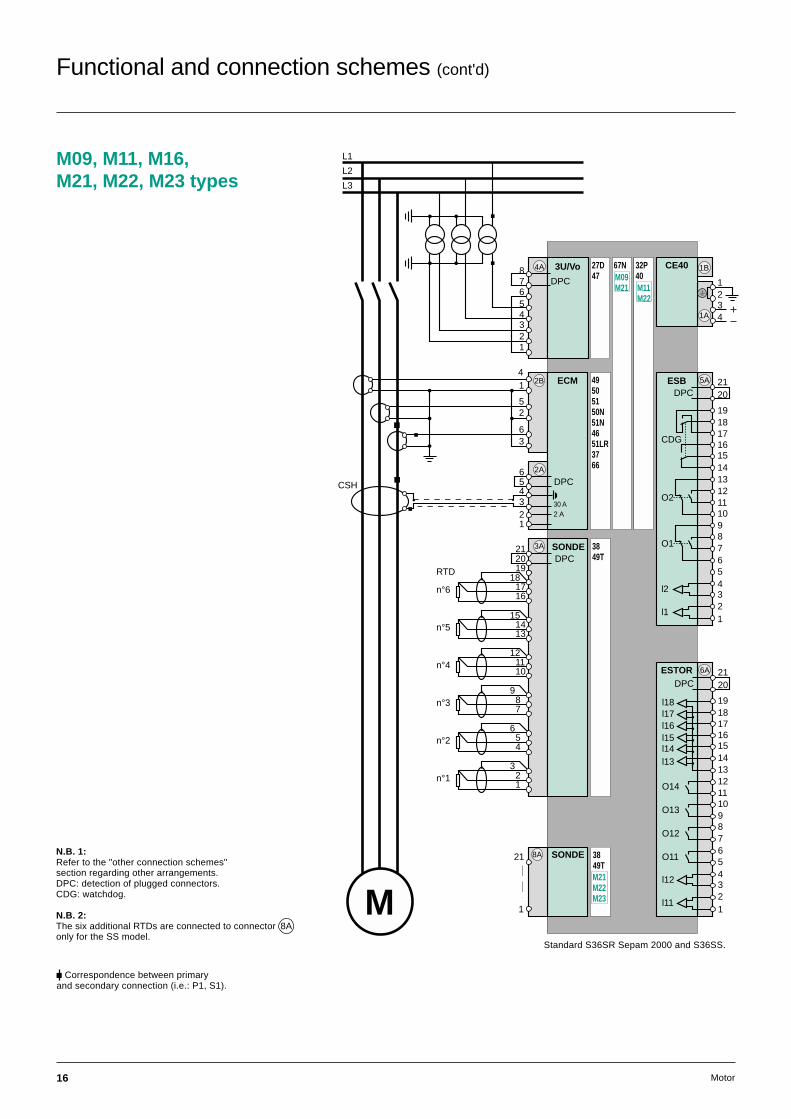
M09, M11, M16,M21, M22, M23 types
Standard S36SR Sepam 2000 and S36SS.
14
52
63
ECM2B
L1
L2
L3
CE40 1B
1A 4
23
1
56
432
2A
30 A
DPC
2 A
ESB 5A
DPC
O2
O1
l2
l1
CDG
2120
19
1716
131211
5
10
1415
18
76
4
2
98
3
1
49505150N51N4651LR3766
M
2120
19
1716
131211
5
10
1415
18
76
4
2
98
3
1
6A
DPC
O11
l12
l11
O12
O13
O14
l13l14l15l16l17l18
ESTOR
21
1
8A SONDE 3849TM21M22M23
DPC2021
1918
1716
SONDE3A
n°6
151413
n°5
121110
n°4
987
n°3
654
n°2
321
n°1
RTD
3849T
4A 3U/Vo
56
4321
78
DPC
27D47
32P40
67NM09M21 M11
M22
1
CSH
N.B. 1:Refer to the "other connection schemes"section regarding other arrangements.DPC: detection of plugged connectors.CDG: watchdog.
N.B. 2:The six additional RTDs are connected to connector 8Aonly for the SS model.
c Correspondence between primaryand secondary connection (i.e.: P1, S1).
Functional and connection schemes (cont'd)
17Motor
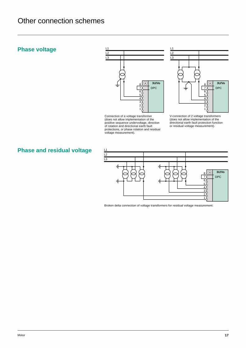
Other connection schemes
Phase and residual voltage
Broken delta connection of voltage transformers for residual voltage measurement.
56
4321
3U/Vo
L1
L2
L3
78
DPC
A
Phase voltage
56
4321
3U/Vo
L1
L2
L3
78
DPC
A
56
4321
3U/Vo
L1
L2
L3
78
DPC
A
Connection of a voltage transformer(does not allow implementation of thepositive sequence undervoltage, directionof rotation and directional earth faultprotections, or phase rotation and residualvoltage measurement).
V-connection of 2 voltage transformers(does not allow implementation of thedirectional earth fault protection functionor residual voltage measurement).

18 Motor
Phase current
A
ECAcable CCA 601
L3
L2
L1
L1 L2 L3
2L1
2L2
2L3
14
52
63
ECMB
L1 L2 L3
Connection of 2 current transformers.Connection of special-purpose CSP sensorsaccording to type of Sepam 2000.
c Correspondence between primaryand secondary connection (i.e.: P1, S1).
Residual currentwith CT 1A or 5A
For connection of 1 A transformers make5 turns at the CSH 30 primary
14
52
63
56
4321
2A
30 A
DPC
2 A
ECM2B
L1 L2 L3
CT + CSH 30
CSH30
56
4321
ECM
30 A
DPCP1
P2
S2
S1 2 ACT + CSH30
5 turns
A
1
CSH30
Other connection schemes (cont'd)
with sensors other than CSH 120 or CSH 200
(*) The core balance CT-ACE 990 and ACE 990-Sepam 2000 connections depend on thetransformer ratio of the core balance CT and the current to be measured.
ACE 990
L1 L2 L3
56
4321
ECM
DPC
2A
*
*
1/n
50 ≤ n ≤ 1500

19Motor
Examples of connections
Logic input and output boards
Circuit breaker or latching contactor trippingby a shunt-trip coil.
Circuit breaker tripping by an undervoltagerelease coil.
Tripping by undervoltage release coil of acontactor with impulse or latched order control.
ESTOR board
ESTOR
DPC21
20
O11
7
4
3
2
1
l12
l11
8
5
6
10
9
12
11
O12
O13
O14
13
19
17
16
18
14
15
l13
l14l15
l16
l17
l18
A
terminals data connected to ESTOR board
19 I18 remote control enable: enables closingand acknowledgment control via the serial link:contact closed for enable
18 I17 "drawn out" position: contact closed for drawn out
17 I16 pole pressure: contact closed for breaking pole fault
16 I15 external protection tripping: normally closed or normallyopen contact according to set up
15 I14 start: NO contact
14 I13 stop: NO contact for shunt-trip coil,NC contact for undervoltage release coil
13 common
12 O14 transmit blocking input (BI)11
10 O13 device fault (pressure fault or control fault)9
8 O12 fault tripping7
6 O11 RTD alarm or RTD fault5
4 I12 load shedding: normally open contact3
2 I11 earthing switch: contact open for earthing switch open1
* if opening control via input I13 is not used (direct control outside Sepam 2000):- for a shunt trip coil, I13 = 0 permanently,- for an undervoltage release coil, I13 = 1 permanently.N.B. The inputs are potential-free and the supply source is external.
ESB
DPC21
20
19
17
16
13
12
11
5
O2
10
14
15
18
O1
9
8
7
6
4
3
2
1
l2
l1
trippingcoil
open
closingcoil
CDG
A ESB
DPC21
20
19
17
16
13
12
11
5
O2
10
14
15
18
O1 7
6
4
3
2
1
l2
l1
trippingcoil
open
closingcoil
CDG
9
8
A ESB
DPC21
20
19
17
16
13
12
11
5
O2
10
14
15
18
O1
9
8
7
6 contactorcoil
open
CDG
A
l2
l1
4
3
2
1
N.B. The inputs are potential-free and require an external power supply source.
ESB board

20 Motor
remote indications address
logic input status
logic output status
operation counter C1
phase fault trip counter C2
running hours counter C3
control fault: KTS1tripping or matching
remote control open/close fault KTS2
position/remote control KTS3discrepancy
external protection tripping KTS4
Sepam not reset KTS5(after fault)
device closed KTS10
device drawn out KTS11
breaking pole fault KTS12
earthing switch closed KTS13
remote control enable KTS14
phase overcurrent KTS15
earth fault KTS16
thermal overload KTS17
negative sequence/unbalance KTS18
excessive starting time KTS19
locked rotor KTS20
phase undercurrent KTS21
directional earth fault KTS22
starts per hour KTS23
reverse real power KTS24
reactive overpower KTS25
RTD alarm KTS26
RTD trip KTS27
RTD fault KTS28
motor differential KTS29
load shedding or positive KTS30sequence undervoltage
restart KTS31
transmit "blocking input" KTS32
inhibited disturbance recording KTS50
remote setting disable KTS51
Communication
Sepam 2000 / remotemonitoring and controlcommunication system.
MERLIN GERIN
Communication tableremote measurements
phase currents
peak demand phase currents
phase-to-phase and phase-to-neutral voltage
frequency
real power
reactive power
peak demand real power
peak demand reactive power
power factor (p.f.)
inductive or capacitive network
temperatures (RTDs)
accumulated real energy
accumulated reactive energy
tripping currents
thermal capacity used
residual current
residual voltage
cumulative breaking current
number of trips
start inhibit time delay
number of starts before inhibition
remote readout-remote setting
protection function curves, set points, time delays,angles...
control logic time delays
remote control orders
ÒstopÓ KTC33
ÒstartÓ KTC34
fault acknowledgment (reset) KTC35
peak demand phase currents KTC36zero reset (clear)
peak demand W and VAr KTC37zero reset (clear)
tripping currents KTC38zero reset (clear)
inhibition disturbance recording KTC50
automatic disturbance KTC51recording triggering
manual disturbance recording triggering KTC52
The data above is available via the optional communicationlink.The measurements available depend on the type ofSepam 2000.
IntroductionThe communication option can be used to connect Sepam 2000 to a remote monitoring and control systemequiped with a master communication channel.
Sepam can be equiped with different communication options:c Jbus/Modbus, master-slave protocol with RS485 type 2-wire physical link (300 to 38400 baud rate).c FIPIO, FIP ISIS (please consult us).

21Motor
Characteristics
Electrical characteristicsanalog inputs
current transformer 1 A CT < 0.001 VA10 A to 6250 A ratings 5 A CT < 0.025 VA
voltage transformer 100 to 120 V > 100 kΩ220 V to 250 kV ratings
logic inputs
voltage 24/30 Vdc 48/127 Vdc 220/250 Vdc
consumption 4 mA 4 mA 3 mA
auxiliary power supply
DC voltage 24/30 Vdc 48/127 Vdc 220/250 Vdc
typical consumption 18 W 19.5 W 21 W
logic outputs (relays)
voltage 24/30 Vdc 48 Vdc 125 Vdc 220/250 Vdc
rated current 8 A 8 A 8 A 8 A
400 ms overload 15 A 15 A 15 A 15 A
making capacity 15 A 15 A 15 A 15 A
breaking capacity : DC with resistive load 8 A 4 A 0,8 A 0,3 ADC at L/R = 20 ms 6 A 2 A 0.4 A 0.15 ADC at L/R = 40 ms 4 A 1 A 0.2 A 0.1 AAC with resistive load 8 A 8 A 8 A 8 AAC with p.f. = 0.3 5 A 5 A 5 A 5 A
Environmental characteristicselectric insulation
dielectric withstand IEC 60255-5 2 kV - 1 mn (1)
1.2/50 µs impulse wave withstand IEC 60255-5 5 kV (2)
climatic withstand
operation IEC 60068-2- 1 and 2 - 5 °C to + 55 °CIEC 60068-2-14 - 5 °C to + 55 °C
storage IEC 60068-2 - 25 °C to + 70 °Cdamp heat IEC 60068-2 -3 93% RH at 40 °C
56 days (storage)10 days (operation)
corrosion influence IEC 60654-4 class I
mechanical robustness
degree of protection IEC 60529 IP 51 front face
vibrations IEC 60255-21-1 class I
shocks / jolts IEC 60255-21-2 class I
earthquakes IEC 60255-21-3 class I
fire resistance IEC 60695-2-1 glow wire
electromagnetic compatibility
radiated fields IEC 60255-22-3 class x 30 V/mIEC 61000-4-3 class III 10 V/m
electrostatic discharge IEC 60255-22-2 class IIIIEC 61000-4-2 class III
damped 1 MHz wave IEC 60255-22-1 class III
5 ns electrical fast transients/burst IEC 60255-22-4 class IVIEC 61000-4-4 class IV
1.2/50µs - 8/20µs surge immunity IEC 61000-4-5 class III 2 kV differential mode (42 Ω)1 kV common mode (42 Ω)
conducted disturbance emission EN 55022/CISPR22 class B with auxiliarypower supply (3)
radiated field emission EN 55022/CISPR22 class B (4)
Ò Ó marking on our product guarantees their conformity to European directives.(1) except for communication 1.4 kVdc and auxiliary power supply 2.8 kVdc(2) except for communication 3 kV common mode, 1 kV differential mode(3) EN 50081-1 generic standard(4) EN 50081-2 generic standard
22 Motor
Installation
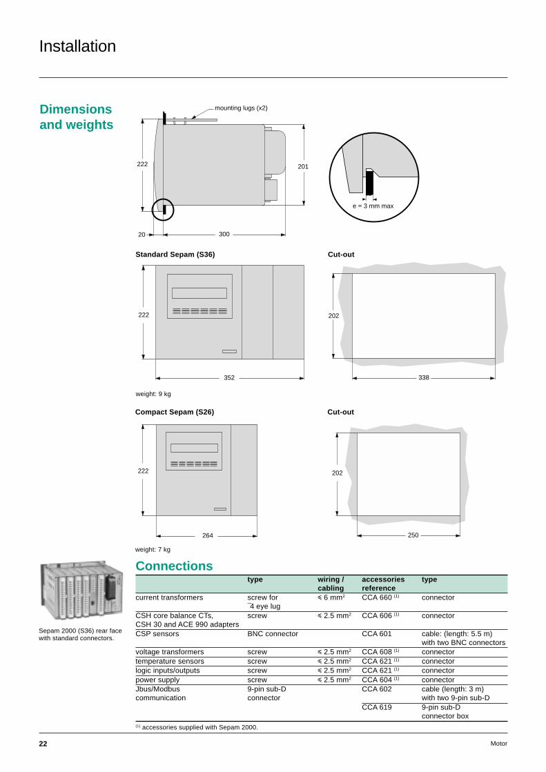
Dimensionsand weights
201
20 300
222
mounting lugs (x2)
Standard Sepam (S36) Cut-out
weight: 9 kg
352
222
Sepam 2000 (S36) rear facewith standard connectors.
Compact Sepam (S26) Cut-out
250
202222
264
weight: 7 kg
e = 3 mm max
338
202
Connectionstype wiring / accessories type
cabling referencecurrent transformers screw for i 6 mm2 CCA 660 (1) connector
¯4 eye lugCSH core balance CTs, screw i 2.5 mm2 CCA 606 (1) connectorCSH 30 and ACE 990 adaptersCSP sensors BNC connector CCA 601 cable: (length: 5.5 m)
with two BNC connectorsvoltage transformers screw i 2.5 mm2 CCA 608 (1) connectortemperature sensors screw i 2.5 mm2 CCA 621 (1) connectorlogic inputs/outputs screw i 2.5 mm2 CCA 621 (1) connectorpower supply screw i 2.5 mm2 CCA 604 (1) connectorJbus/Modbus 9-pin sub-D CCA 602 cable (length: 3 m)communication connector with two 9-pin sub-D
CCA 619 9-pin sub-Dconnector box
(1) accessories supplied with Sepam 2000.

23Motor
Notes
PCRED398020EN /1ART.88621
This document has beenprinted on ecological paper.
Schneider Electric Postal addressF-38050 Grenoble cedex 9Tel: 33 (0)4 76 57 60 60Telex: merge 320842 Fhttp://www.schneider-electric.com
As standards, specifications and designs change fromtime to time, please ask for confirmation of the informationgiven in this publication.
Publishing: Schneider ElectricDesign, production: IdraPrinting:
12 / 1999
Rcs Nanterre B 954 503 439
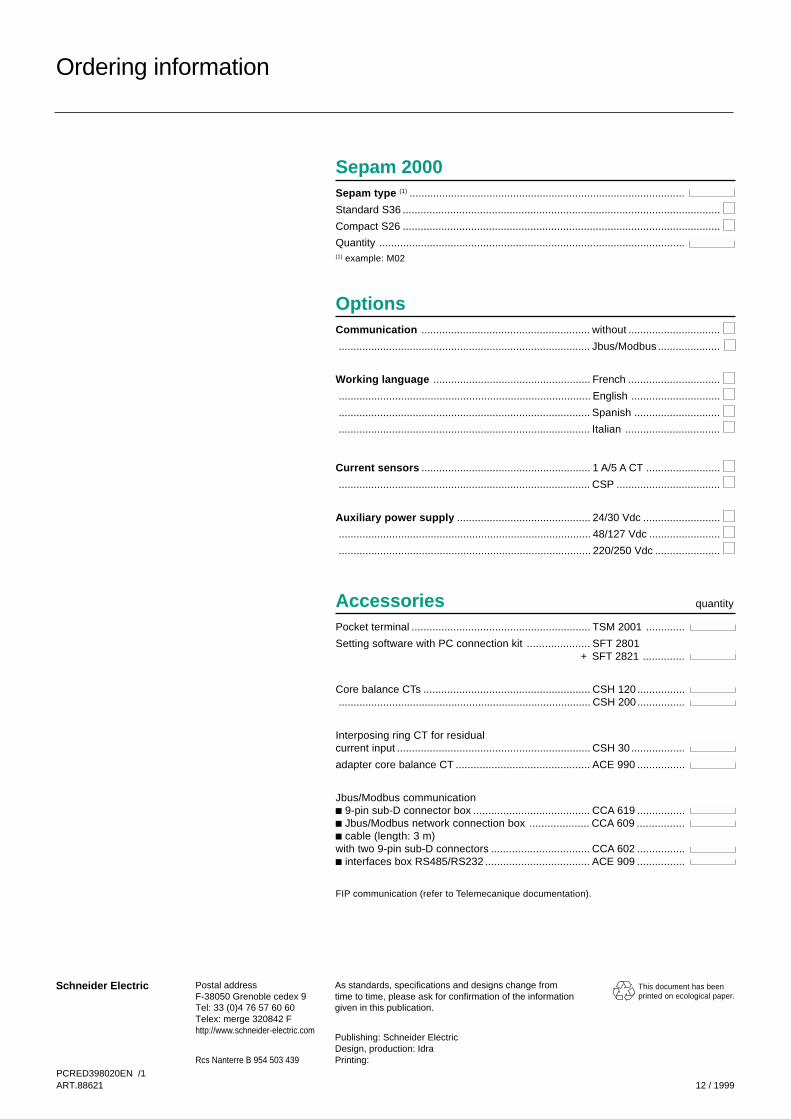
Sepam 2000Sepam type (1) .............................................................................................
Standard S36 ...........................................................................................................
Compact S26 ...........................................................................................................
Quantity .......................................................................................................(1) example: M02
OptionsCommunication ......................................................... without ...............................
..................................................................................... Jbus/Modbus .....................
Working language ..................................................... French ...............................
..................................................................................... English ..............................
..................................................................................... Spanish .............................
..................................................................................... Italian ................................
Current sensors ......................................................... 1 A/5 A CT .........................
..................................................................................... CSP ...................................
Auxiliary power supply ............................................. 24/30 Vdc ..........................
..................................................................................... 48/127 Vdc ........................
..................................................................................... 220/250 Vdc ......................
AccessoriesPocket terminal ............................................................ TSM 2001 .............
Setting software with PC connection kit ..................... SFT 2801+ SFT 2821 ..............
Core balance CTs ........................................................ CSH 120 ..................................................................................................... CSH 200 ................
Interposing ring CT for residualcurrent input ................................................................. CSH 30 ..................
adapter core balance CT ............................................. ACE 990 ................
Jbus/Modbus communicationc 9-pin sub-D connector box ....................................... CCA 619 ................c Jbus/Modbus network connection box .................... CCA 609 ................c cable (length: 3 m)with two 9-pin sub-D connectors ................................. CCA 602 ................c interfaces box RS485/RS232 ................................... ACE 909 ................
FIP communication (refer to Telemecanique documentation).
Ordering information
quantity