protection of the mmcs of hvdc transmission systems...
TRANSCRIPT

Journal of Power Electronics, to be published 1
Protection of the MMCs of HVDC Transmission Systems against DC Short-Circuit Faults
Thanh Hai Nguyen* and Dong-Choon Lee†
*Department of Electrical Engineering, The Petroleum Institute, Abu Dhabi, UAE †Department of Electrical Engineering, Yeungnam University, Gyeongsan, Korea
Abstract
This paper deals with the blocking of DC-fault current during DC cable short-circuit conditions in HVDC (High-Voltage DC) transmission systems utilizing Modular Multilevel Converters (MMCs), where a new SubModule (SM) topology circuit for the MMC is proposed. In this SM circuit, an additional Insulated-Gate Bipolar Translator (IGBT) is required to be connected at the output terminal of a conventional SM with a half-bridge structure, hereafter referred to as HBSM, where the anti-parallel diodes of additional IGBTs are used to block current from the grid to the DC-link side. Compared with the existing MMCs based on full-bridge (FB) SMs, the hybrid topologies of HBSM and FBSM, and the clamp-double SMs, the proposed topology offers a lower cost and lower power loss while the fault current blocking capability in the DC short-circuit conditions is still provided. The effectiveness of the proposed topology has been validated by simulation results obtained from a 300-kV 300-MW HVDC transmission system and experimental results from a down-scaled HVDC system in the laboratory.
Key words: current-fault blocking capability, DC-cable short circuit, HBSM, HVDC, MMC
I. INTRODUCTION
Nowadays, the MMC has been considered as a preferable solution in the application of HVDC transmission systems to integrate distant renewable energy sources with an AC network [1]. With its modular structure, the MMC employs a large number of the SubModule (SM) connected in series, which is easily extensible for applications with different ranges of voltages and powers [2], [3]. The attractive features of the MMC such as its low power losses, small-sized filters, low voltage stress of switches, etc, have been described in previous articles [4], [5]. For MMC-based HVDC transmission systems, the basic building block is a sub-module. A schematic diagram of the MMC-based HVDC is shown in Fig. 1. The half-bridge-based SM is the main configuration of the MMC, which is a loss-effective and cost-effective structure. One of the significant drawbacks of a MMC-HVDC using an HBSM is its lack of DC-fault current blocking capability, where the freewheeling diode operates as a rectifier and produces an excessively high DC fault current from the AC grid through the short-circuit point in the DC link as illustrated in Fig. 2
[6]. So far, there have been three kinds of approaches that theoretically and practically deal with DC-cable faults in HVDC systems [7]-[14]. First of all, a circuit breaker is a classical and simple solution to isolate faults. For fault in an HVDC system, either AC or DC circuit breakers (CBs) may be adopted [9]. With AC circuit breakers, the response of the AC mechanical switchgears is very slow (it takes about 2-3 fundamental cycles). This causes a tremendous fault current, which results in damage to the converter devices as well as the DC cables. In addition, the restarting time of AC circuit breakers after the clearance of a fault is long (around 10s), which is not allowable for wind farms integrated to the grid according to grid code requirements. Meanwhile, DC circuit breakers can provide fast responses for blocking fault current. However, this technology is short in terms of practical field experience and expensive [7], [8]. It is presently under development for high power applications. The second solution is to utilize thyristors (SCRs) with a higher thermal capability compared to the freewheeling diodes in the SMs, where either an anti-parallel or double SCRs conducting bidirectional current are connected to the terminal of the HBSM [9]. For this installation, the thyristors can bypass the fault currents and protect the freewheeling diodes during short-circuit conditions. However, this method cannot isolate DC faults, which may damage the DC cables due to excessively high fault currents.

2 Journal of Power Electronics, to be published
Recently, modifying the structures of SMs to embed the DC-fault current blocking capability in the MMC-HVDC systems has been paid significant attention, and is regarded as a preferable solution to the use of DC circuit breakers [6], [10]-[14]. The first modified structure is the full-bridge-based SM (FBSM), which utilizes the capacitor voltage of the SM to create reverse voltage for blocking the conduction of the freewheeling diodes [6], [11]. However, the number of power devices of the SM is doubled compared with the HBSM. This increases the cost of high power MMC systems. It also increases the power loss since the current in each SM flows through two power devices instead of one as is the case with the HBSM. In order to decrease the number of the switches, a hybrid structure for an MMC that combines FBSMs and HBSMs has been introduced [11], [12]. The MMC is still able to block fault current and needs fewer semiconductor devices, which results in a lower power loss than that of an MMC based on FBSMs. Another SM scheme utilizing clamp-double SMs has been presented in [13], [14]. Merlin at al. [15] presented alternate arm converters (AAC), where each arm of the AAC consists of a stack of H-bridge SMs and a director valve. However, for these topologies, the power
loss and cost are increased and the system volume is bulky since the number of the devices is still high. This study is an extension of [16], which deals with the issue of embedding the fault current blocking capability into an MMC-based HVDC system. For further details, a new scheme for the SMs in an MMC is proposed in this paper, which consists of an additional IGBT connected at the output terminal of a conventional half-bridge SM. With the suggested SM, the MMC-HVDC system keeps its control and operation abilities similar to the existing ones. In addition, compared with MMC systems with the current-fault blocking capability, the proposed MMC offers the lowest cost and power losses. The efficiency of the proposed MMC is about 98.86% compared with efficiencies of 98.34%, 98.75%, 98.79%, and 98.57% for MMCs based on FBSMs, hybrid SMs, clamp-double SMs, and AACs, respectively. The feasibility of the proposed topology is verified by simulation results for a 300-kV 300-MW HVDC transmission system using a 7-level MMC. In addition, experimental results obtained with the HVDC system with a 3-level MMC in the laboratory are provided. These results demonstrate the effectiveness of the proposed scheme.
II. SM CIRCUITS IN AN MMC
A configuration of an HVDC transmission system with MMCs for connecting the two grids or an offshore wind farm and an onshore grid is shown in Fig. 1. The three-phase MMC consists of six arms, where each converter arm is constituted by N series-connected SMs and an inductor [17]. So far, several different SM circuit topologies have been introduced as follows.
1) Half-Bridge SMs
The simplest structure for the SMs of MMCs is the half bridge which utilizes a complementary switch pair and a DC capacitor as shown in Fig. 3. This type of MMC has low power losses and a low cost. The major disadvantage of the HBSM-MMC is that DC-fault current blocking capability is not provided. Therefore, at a DC short-circuit fault, the freewheeling diodes in the SMs create a path for the fault current from the AC voltages to the short-circuit point in the DC side.
2) HBSMs with Bypassed Thyristors
In order to protect the switches in an MMC during DC short-circuit faults, two SCRs are connected in parallel with the lower IGBT of the HBSM as shown in Fig. 3 [9]. Under normal operation, the SCRs are turned off. When the short-circuit fault is detected, the SCRs are turned on, which conducts the fault current and by-passes the freewheeling diodes in the HBSM. It is noted that the thermal capacity of the SCRs is higher than that of the freewheeling diodes. Therefore, the excessively high fault current flows mainly through the SCRs, by which the anti-parallel diode of the
Grid Tran.
SM1
SM2
SMN
SM1
SM2
SMN
SM1
SM2
SMN
SM1
SM2
SMN
SM1
SM2
SMN
SM1
SM2
SMN
MMC1MMC2
+
-
DC cables
DC cables
2dcV
1. Grid2. WF
2dcV
o
a
bc
Fig. 1. Configuration of HVDC system based on the MMCs.
MMC1
Grid
PCC
DC cables
Fault
Fig. 2. Freewheeling current for DC short-circuit fault.

Protection of MMC of HVDC Transmission … 3
IGBT is protected from damage. However, the fault current cannot be completely isolated in the converter, which may damage the other components of the converter system.
3) Full-Bridge SMs
As shown in Fig. 3(a), the FBSM is composed of four identical switches and a DC capacitor [6], which can generate three levels of output voltage with negative, zero, and positive values of the DC capacitor voltage. At a DC short-circuit fault, when all of the IGBTs of the SMs are deactivated, the capacitor voltages of the SMs in the upper and lower arms in different leg produce reverse bias voltages for the freewheeling diodes as shown in Fig. 3(c). Therefore, the fault currents from the AC side are blocked. Thus, an MMC with FBSMs provides current fault blocking capability. However, the number of the switches is doubled compared with the HBSM, which causes significantly higher power losses and increases in both cost and size.
4) Hybrid Structure of HBSMs and FBSMs
The converter arm of an MMC based on hybrid SMs is shown in Fig. 3(d), which utilizes a combination of HBSMs and FBSMs connected in series in the converter arm referred to as hybrid SMs [11]. For this structure, the hybrid SM-based MMC possesses the DC-fault current blocking capability, while offering lower losses and cost compared to the FBSM-MMC. However, the reverse bias voltage is lower than that of the FBSM-MMC.
5) Clamp-Double SMs
An alternative SM was proposed in [18], which is shown in Fig. 3(e). The fifth IGBT (T5) remains in the on-state all the time during the normal operation. When a short-circuit fault is detected, all of the switches are switched off. Then, the clamp-double SMs can generate reserve bias voltages to drive the fault currents to decrease to zero. In this structure, many additional devices are required compared with other topologies.
III. PROPOSED SM TOPOLOGY FOR MMC-HVDC
A. Proposed SM Circuit
Fig. 4 shows the suggested SM circuit, which consists of three single IGBTs (T1, T2, and T3). An additional single IGBT, T3, is inserted into the conventional HBSM with T1, and T2 at its output terminal, which can block the current from the AC grid side to the DC link during DC short-circuit conditions due to the inverse connection of additional anti-parallel diodes. A snubber circuit is required for the additional switch, which prevents the switch from damage due to high dv/dt and di/dt conditions at the moment of deactivating all of the IGBTs [19]. The operation principle of the SM in MMC-HVDC systems under normal and fault conditions are described in detail in the following section.
B. MMC-HVDC System with the Proposed SMs - Voltage Stress and Number of Additional Switches
An overall HVDC transmission system based on the suggested SMs for an MMC is shown in Fig. 5, where each arm of the MMC is composed of N submodules, which contain j HBSMs and k new SMs (k + j = N). The SM capacitor voltage is Vdc/N, where Vdc is the DC-link voltage of the HVDC system. The switching states of the SM are shown in Table I, where the output voltage of the SM, v0i, can be either 0 or the capacitor voltage, Vdc/N, depending on the switching states. It can be seen from Table I and Fig. 4 and 5 that the additional switch T3 is continuously turned on during normal operation, where the arm current flows through the anti-parallel diode or the IGBT depending on the arm current direction (ia_up: the upper arm current). It is assumed that the output voltages of the SMs can be kept at the capacitor voltage Vdc/N identically so that the range of the converter arm voltages is from 0 to Vdc. From Fig. 1, by considering the maximum modulation index, the
maximum peak AC phase voltage, _ao peakV , is expressed as
[9]:
Fig. 3. Circuit topologies of submodules. (a) Half-bridge. (b) Half-bridge SM with double thyristors. (c) Full-bridge. (d) Hybrid. (e) Clamp-double SM.
0iv
_a upidcV
N
Fig. 4. Proposed SM circuit.

4 Journal of Power Electronics, to be published
dcV
N
dcV
N
dcV
N
dcV
N
ai
_a upi
_a lowi
dcV
NdcV
N
Fig. 5. HVDC transmission system based on MMC with the proposed SM topologies.
TABLE I. SWITCHING STATES OF SM
T1 T2 T3 v0i Current direction Current path Capacitor states on off on Vdc/N ia_up >0 D1 and D3 charging on off on Vdc/N ia_up <0 T1 and T3 discharging off on on 0 ia_up >0 T2 and D3 unchanged off on on 0 ia_up <0 D2 and T3 unchanged
ase
bse
dcV
N
dcV
N
2llV
k
dcV
N0
0
2llV
k
2llV
k
2llV
k
Fig. 6. Equivalent circuit of phase A and B of MMC during the DC short circuit.
limit( )dcI I
Fig. 7. Flow chart of the protection for the permanent and temporary faults.

Protection of MMC of HVDC Transmission … 5
_1 1
( )2 2
dcao peak dc
VV N VN . (1)
Fig. 6 shows an equivalent circuit for phase A and phase B of the MMC when a short circuit occurs in the DC cables (assuming Vdc=0). The voltage equation for the upper and lower arms can be expressed as:
2
01
0N
i abi
v v
(2)
where abv is the line-to-line grid voltage.
It can be seen in Fig. 6 that when a fault occurs the conventional HBSMs are bypassed through the freewheeling diode D2. Thus, (2) can be rewritten as:
2
01
0k
i abi
v v
(3)
where 0iv is the output voltage of the proposed SMs during
the fault. It is assumed that the switches of the proposed SMs in the MMC are identical. Therefore, the output voltage of each SM can be expressed as:
0 2ab
i
vv
k . (4)
Considering the peak value of the line-to-line grid voltage, the maximum value of the output voltage of the proposed SMs as well as the voltage drop in the additional switches of
the proposed SMs, 0 maxiv , is determined as:
0 max 2ll
i
Vv
k (5)
where Vll is the peak value of the line-to-line grid. It is known that the MMC in HVDC systems is operated for the boost action. For controllability, the grid voltage is chosen as about 90% of the maximum generated voltage of the MMC. Therefore, the relationship between the grid voltage and the HVDC-link voltage is expressed as:
0.9 3 0.78ll ao peak dcV V V . (6)
If the voltage rating of the additional switches is selected as that of the switches in the HBSMs, then from (4) and (5) the number of SMs inserted into one arm of the MMC has to satisfy the following condition:
0.78
2dc dcV V
N k . (7)
Finally:
0.39k N . (8)
It is worth noting that the number of the additional IGBT can be reduced if its voltage rating is high enough according to (5) and (6). In this case, the power loss, cost, and volume of the whole converter can be further reduced, which depend on the characteristics and types of the IGBT used.
C. Overall Control of MMCs and a Protection Scheme of the MMC-HVDC during Faults
In an HVDC transmission system, an MMC integrated with an onshore grid is normally used to control the HVDC-link voltage and to regulate the AC grid voltage through the reactive power regulation. The control algorithm of the MMC has been described in detail in [4]. The two major control loops for the HVDC-link voltage and the grid reactive power are employed, where these controller outputs are the dq-axis current references for the inner current control loops in the synchronous reference frame. In addition, the average control for the converter leg voltages and the balancing control for the capacitor voltages of the SMs are required for the control of the MMC [20]. In this study, carrier-phase-shift pulse-width modulation is applied [21]. Regarding the protection function of the MMC, when a short circuit in the DC cables occurs, the DC-link and grid currents are immediately increased to extremely high levels. The short-circuit condition is determined as the currents in the system reach the threshold value, Ilimit, which is selected as 2 p.u. Then, all of the IGBTs in the MMC are turned off immediately. Due to the reverse connection of the anti-parallel diode (D3) of the additional IGBT, the freewheeling effect of the diode rectifier (D2) of the SMs is cleared, resulting in no path for the fault current. Fig. 7 shows a flow chart of the protection scheme, where both temporary and permanent faults are taken into account. When a fault is detected, all of the IGBTs are switched off. As a result, the fault current is blocked.
IV. LOSS AND COST COMPARISONS OF MMCS
BASED ON SMS
As known from the analysis in the previous sections, the fundamental operation and controllability of MMCs with the proposed SM circuit are similar to those of the HBSM-MMC. In addition, the fault-current blocking capability of the proposed MMC is obtained similarly to that of the existing ones such as the FBSM-MMC, the hybrid-SM MMC, and the clamp-double-SM MMC [22]. However, some other factors should be considered such as power losses and cost. In this study, for a simple comparison, the losses and cost of the switching devices and gating drivers of different SMs of MMCs are investigated. Consequently, the number of the semiconductor devices and the number of gating drivers required for the MMC-HVDC with different types of SMs with the same 300-kV and 300-MW power ratings are listed in Table II. For evaluating the total cost of the MMCs, the prices of the IGBTs (CM1200HA-66H) and gate drivers (2SD315AI) in Table II are 675.00 $US and 192.50 $US, respectively, and the cost of the diode module (RM900HC-90S) is 570.00 $US [23]. The analysis results show that the device cost of the

6 Journal of Power Electronics, to be published
MMC-HVDC based on the proposed SMs is the lowest compared with the existing ones.
In addition, from the manufacturer datasheet, the power losses of different types of MMCs are evaluated as shown at the bottom of Table II, where a simple and well-known method for the loss calculation of MMCs is used [5], [24]. It is assumed that the MMCs are operated at their rated power. It is seen in Table II that the power loss of the proposed topology is about 1.14%, which is lowest compared to those of the FBSM-MMC, the hybrid-SM MMC, the clamp-double-SM MMC, the unipolar hybrid SM MMC, and the AACs of 1.66%, 1.25%, 1.21%, 1.25%, and 1.43%, respectively. It is worth noting that if different types of switches with low conduction losses are used for the additional switches for the proposed topology, the total power losses of the MMC can be further reduced.
V. SIMULATION RESULTS
To validate the feasibility of the proposed scheme, simulations for an HVDC transmission system based on an MMC with the introduced SM circuits have been carried out. As previously mentioned, this study mainly focuses on the fault current blocking capability of the MMC. Therefore, the HVDC system shown in Fig. 1 is adopted, where a single MMC is integrated with the grid, while the other end of the
MMC is represented by a DC source. In addition, an MMC with a low number of levels is implemented for ease of
TABLE II. DEVICE COMPARISON FOR DIFFERENT TYPES OF MMCS
MMCs Parameters
Full-bridge MMC
Hybrid MMC (HB+FB-MMC)
Clamp-double SMs
Unipolar Hybrid MMC
AAC Proposed SM
MMC
Ratings 300 MW;
300 kV; 866 A 300 MW;
300 kV; 866 A 300 MW;
300 kV; 866 A 300 MW;
300 kV; 866 A 300 MW;
300 kV; 866 A 300 MW;
300 kV; 866 A Number of levels 201 201 201 201 128 201
Number of SMs/arm 200 (100HB+100FB) 200 200 127 200 Device ratings 3.3 kV; 1.2 kA 3.3 kV; 1.2 kA 3.3 kV; 1.2 kA 3.3 kV; 1.2 kA 3.3 kV; 1.2 kA 3.3 kV; 1.2 kA
Additional devices per arm
IGBTs 0 0 1 x100 = 100 1 x100 = 100 600 0.4 x 200 = 80 Diodes 0 0 2 x 100 = 200 1 x 100 = 100 0 0
Numbers of devices per arm
IGBTs 4x200=800 (2+4)x100=600 2x200+100=500 2x200+100=500 608 2x200+80=480 Diodes 0 0 200 100 0 0
Number of devices in total
IGBTs 800 x 6 = 4,800 600 x 6 = 3,600 500x6=3,000 500x6=3,000 3648 480x6=2,880 Diodes 0 0 200x6=1,200 100x6=600 0 0
Estimated device cost 8,328,192 $US
(166.7%) 6,246,144 $US
(125%) 5,889,000 $US
(118%) 5,547,000 $US
(111%) 6,329,426 $US
(126.7%) 4,996,800 $US
(100%)
Estimated power loss 1.66%
(4,986 kW) 1.25%
(3,739.5 kW) 1.21%
(3,637.5 kW) 1.25%
(3,739.5 kW) 1.43%
(4,310.6 kW) 1.14%
(3,408.6 kW)
TABLE III. PARAMETERS OF HVDC BASED ON MMC
Parameters Values Rated power 300 MW
AC grid voltage 33 kV / 60 Hz Transformer (Y/∆) 33/160 kV
DC-link voltage 300 kV Number of SMs per arm 6
DC voltage of SMs 50 kV Capacitance o SMs 200 µF
Arm inductance 10 mH Resistance of DC cable 0.09 Ω/km Inductance of DC cable 0.85 mH/km
agi bgi cgi
*deidei
*qei
qei
dcV
_caps upV _caps lowV
_dc cablei
gridP
Fig. 8. Performance of MMC based on the proposed SMs at the steady state condition. (a) Three-phase grid currents. (b) d-axis grid currents. (c) q-axis grid currents. (d) Grid active power. (e) DC-link voltage of HVDC system. (f) Upper and lower SM capacitor voltages. (g) DC-cable currents.
Protection of MMC of HVDC Transmission … 7
simulation. In this study, a seven-level MMC is employed to verify the effectiveness of the proposed SM scheme. The MMC is operated to deliver an active power of 0.79 p.u. and a reactive power of 0.12 p.u. under steady-state conditions. The system parameters are listed in Table III. The base units of the system parameters such as the power, voltage, and current are set as the system ratings for the analysis, as listed in Table II.
Fig. 8 shows the control performance of an MMC with the proposed SMs under the steady state conditions, where the current controllers in the d-q synchronous reference frame are employed for the grid-connected MMC [4], [25]. Fig. 8(a) shows the three-phase grid currents, which are sinusoidal and balanced. The d-axis and q-axis grid currents are shown in Fig. 8(b) and Fig. 8(c), respectively. These figures demonstrate the satisfactory current control performance of the MMC. Fig. 8(d) shows the grid active power, which is delivered from the offshore side. The HVDC-link voltage is closely regulated to the nominal value of 300 kV as shown in Fig. 8(e). It can be seen in Fig. 8(f) that the capacitor voltages of the upper and lower arm SMs are closely kept toward their
references of 50 kV. The DC current in the HVDC link is shown in Fig. 8(g). A transient response comparison of MMC-HVDC systems based on the conventional and the proposed SM circuits is shown in Fig. 9 and Fig. 10. A line-to-line short-circuit fault occurring in the DC cables at 0.32s is employed to evaluate the response of the MMC, where Fig. 9 shows the performance of the HBSN-MMC, which corresponds to Fig. 10 for the MMC with the proposed ones. The short-circuit fault causes the DC-link voltage to be quickly reduced almost to zero as shown in Fig. 9(a). Then the DC-cable current is significantly increased and is kept severely high even though all of the IGBT of the MMC are turned off as shown in Fig. 9(b). Thus, powers are still transmitted through the freewheeling diodes during the fault as shown in Fig. 9(c). It
dcV
_dc cablei
gridPgridQ
agi bgi cgi
_caps upV _caps lowV
_a upi_a lowi
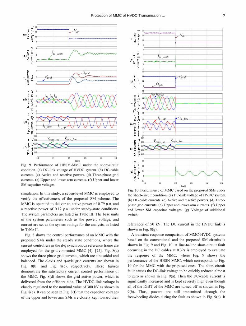
Fig. 9. Performance of HBSM-MMC under the short-circuit condition. (a) DC-link voltage of HVDC system. (b) DC-cable currents. (c) Active and reactive powers. (d) Three-phase grid currents. (e) Upper and lower arm currents. (f) Upper and lower SM capacitor voltages.
gridP
gridQ
agi bgi cgi
_caps upV _caps lowV
_a upi _a lowi
dcV
_dc cablei
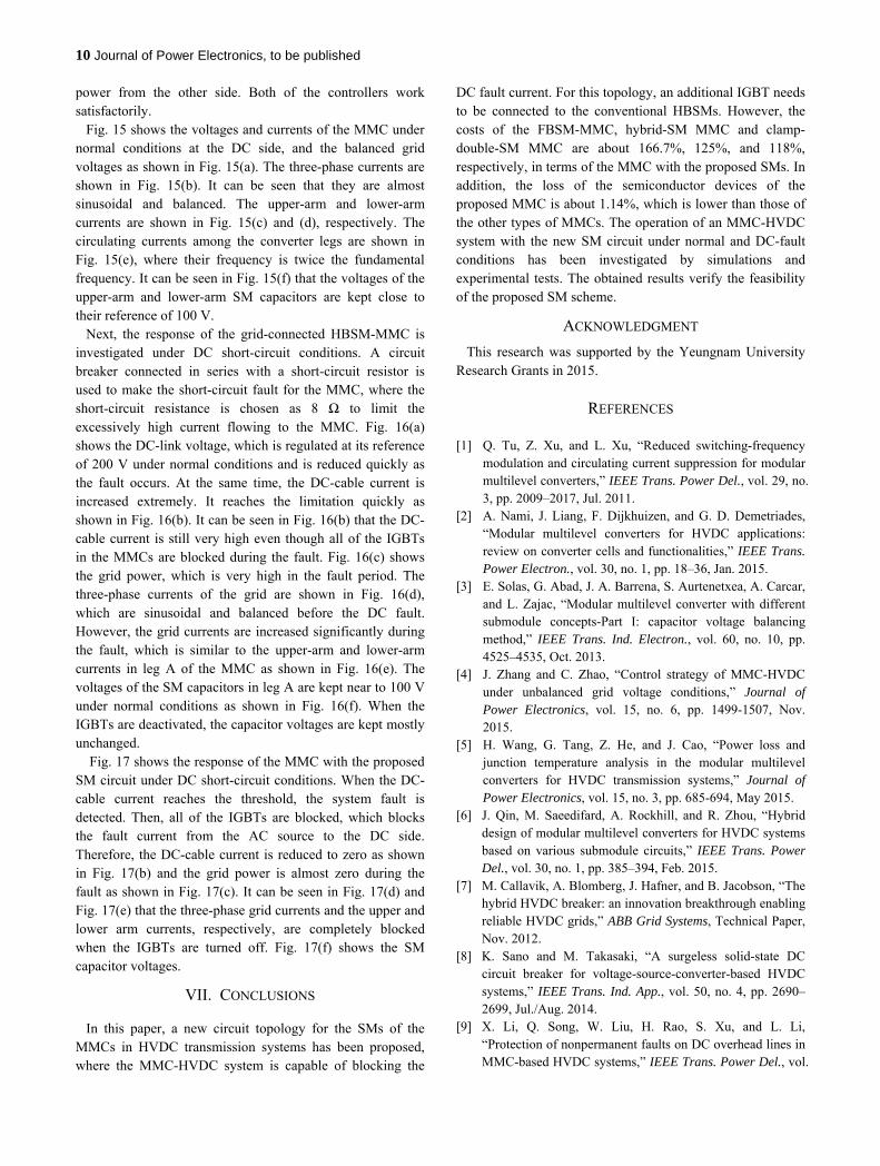
Fig. 10. Performance of MMC based on the proposed SMs under the short-circuit condition. (a) DC-link voltage of HVDC system. (b) DC-cable currents. (c) Active and reactive powers. (d) Three-phase grid currents. (e) Upper and lower arm currents. (f) Upper and lower SM capacitor voltages. (g) Voltage of additional switch.

8 Journal of Power Electronics, to be published
can be seen in Fig. 9(d) that the three-phase grid currents are excessively increased when the fault occurs. Fig. 9(e) shows the upper and lower arm currents, which still flow from the grid to the DC-link side through the freewheeling diodes of the HBSMs. Fig. 9(f) shows the capacitor voltages of the upper and lower arm SMs, which are unchanged since all of the IGBTs are blocked. With the suggested SMs, when the fault current in the DC cable reaching the threshold value is detected, all of the IGBTs are switched off. Then, the fault current is blocked due to the reverse connection of the addition diode on the SMs, where the fault current quickly drops to zero as shown in Fig. 10(b). Consequently, the powers are not delivered through the MMC during the fault condition as shown in Fig. 10(c). It can also be seen in Fig. 10(d) and Fig. 10(e) that the three-phase grid currents and the upper and lower arm currents, respectively, are completely blocked when the IGBTs are turned off. Fig. 10(f) shows the SM capacitor voltages, which are kept unchanged after blocking the IGBTs. It can be seen from Fig. 10(g) that the voltage drop in the additional switch is almost zero under normal conditions due to the on-state of the switch, while it is increased depending on the grid voltage during the fault.
VI. EXPERIMENTAL RESULTS
The operation of an MMC with the proposed SM circuit was also investigated by experimental tests to verify the feasibility of the proposed scheme. Fig. 11 shows the experimental configuration, where an HVDC system consisting of a three-level grid-connected MMC in one station and a DC source
represented by a three-phase diode rectifier in the other side, as shown in Fig. 11(a), were conducted for normal operation. For the investigation under fault conditions, the grid-connected MMC with resistive loads in the DC side was used as shown in Fig. 11(b).
dcL
dcL
loadRscR
MC
dci
aidcL
dcL
dci
220V/60Hz
Diode Rectifier
3-level MMCSlidac Slidac220V/60Hz
ai
3-level MMCSlidac
220V/60Hz
(a)
(b)
Fig. 11. Experimental configuration for (a) normal operation, (b) fault condition.
Fig. 12. Hardware setup.
TABLE IV. MMC PARAMETERS FOR EXPERIMENTS
Parameters Values AC grid voltage 120 V / 60 Hz
Number of SMs per arm 2 SM capacitor voltage 100 V
SM capacitance 2,200 µF Arm inductance 1 mH
Input filter inductance 1 mH DC-cable inductance 1 mH
Short-circuit resistance 8 Ω Carrier frequency 2.5 kHz
gridP
_dc cablei
qei
dcV
Fig. 13. Operation of MMC at normal condition. (a) Grid power. (b) DC-cable current. (c) q-axis current. (d) DC-link voltage.
*dei
dei
qei*qei
Fig. 14. Current control performance of MMC. (a) d-axis currents. (b) q-axis currents.

Protection of MMC of HVDC Transmission … 9
Fig. 12 show the hardware set-up in the laboratory. A main controller board with a DSP chip (TMS320F28335) was adopted, where the carrier phase-shift PWM with a switching frequency of 2.5 kHz was implemented in a Xilinx FPGA device (XC3S400-PQG208EGQ1321) to generate 24 gating PWM signals for the MMC. The parameters of the 3-level MMC are listed in Table IV. The DC-link voltage is controlled at 200 V, where the SM capacitor voltages are balanced at 100 V.
Fig. 13 shows the operation of the HVDC system with the proposed MMC under normal operation, where the MMC is used to control the DC-link voltage, while the amount of real power delivered to the grid is changed by the diode rectifier in other side. Fig. 13(a)-(c) show the grid power, the DC-cable current and the q-axis current, respectively. They have a proportional relationship. It can be seen in Fig. 13(d) that the DC- link voltage is regulated well at its reference of 200 V during the steady state and under the transient conditions of power changes. The current control performance of the MMC is illustrated in Fig. 14. Fig. 14(a) shows the d-axis currents, which are controlled at zero for unity power factor operation. Fig. 14(b) shows the q-axis currents, which are changed according to the
bsease cse
bsiasi csi
bpiapi cpi
bniani cni
0bi0ai 0ci
2cv1cv
3cv4cv
Fig. 15. Voltages and currents of MMC during the normal condition. (a) Grid phase voltages. (b) Grid phase currents. (c) Upper-arm currents. (d) Lower-arm currents. (e) Circulating currents. (f) Voltages of upper- and lower-arm SM capacitors.
dcV
_dc cablei
gridP
bsiasi csi
a_lowi_a upi
c1,2v
c3,4v
Fig. 16. Response of MMC with HBSMs. (a) DC-link voltage. (b) DC-cable current. (c) Grid power. (d) Grid phase currents. (e) Upper- and lower-arm currents. (f) Voltages of upper- and lower-arm SM capacitors.\
60V/div
120
4A/div
8
200W/div600
2A/div
0
2A/div
0
2.5V/div
100
DC
-lin
k vo
ltag
e (V
)
(a)
DC
-cab
le
curr
ent (
A)
(b)
Gri
d ac
tive
pow
ers
(W)
(c)
Phas
e cu
rren
ts
of th
e gr
id (
A)
(d)
Upp
er a
nd lo
wer
ar
m c
urre
nts
(A)
(e)
SM c
apac
itor
volt
ages
(V
)
(f)
dcV
_dc cablei
gridP
bsiasicsi
a_upi_lowai
c1,2v
c3,4v
Fault conditionNormal condition
T/div=20[ms] Fig. 17. Response of MMC with proposed SM circuits. (a) DC-link voltage. (b) DC-cable current. (c) Grid power. (d) Grid phase currents. (e) Upper- and lower-arm currents. (f) Voltages of upper- and lower-arm SM capacitors.
10 Journal of Power Electronics, to be published
power from the other side. Both of the controllers work satisfactorily. Fig. 15 shows the voltages and currents of the MMC under normal conditions at the DC side, and the balanced grid voltages as shown in Fig. 15(a). The three-phase currents are shown in Fig. 15(b). It can be seen that they are almost sinusoidal and balanced. The upper-arm and lower-arm currents are shown in Fig. 15(c) and (d), respectively. The circulating currents among the converter legs are shown in Fig. 15(e), where their frequency is twice the fundamental frequency. It can be seen in Fig. 15(f) that the voltages of the upper-arm and lower-arm SM capacitors are kept close to their reference of 100 V. Next, the response of the grid-connected HBSM-MMC is investigated under DC short-circuit conditions. A circuit breaker connected in series with a short-circuit resistor is used to make the short-circuit fault for the MMC, where the short-circuit resistance is chosen as 8 Ω to limit the excessively high current flowing to the MMC. Fig. 16(a) shows the DC-link voltage, which is regulated at its reference of 200 V under normal conditions and is reduced quickly as the fault occurs. At the same time, the DC-cable current is increased extremely. It reaches the limitation quickly as shown in Fig. 16(b). It can be seen in Fig. 16(b) that the DC-cable current is still very high even though all of the IGBTs in the MMCs are blocked during the fault. Fig. 16(c) shows the grid power, which is very high in the fault period. The three-phase currents of the grid are shown in Fig. 16(d), which are sinusoidal and balanced before the DC fault. However, the grid currents are increased significantly during the fault, which is similar to the upper-arm and lower-arm currents in leg A of the MMC as shown in Fig. 16(e). The voltages of the SM capacitors in leg A are kept near to 100 V under normal conditions as shown in Fig. 16(f). When the IGBTs are deactivated, the capacitor voltages are kept mostly unchanged. Fig. 17 shows the response of the MMC with the proposed SM circuit under DC short-circuit conditions. When the DC-cable current reaches the threshold, the system fault is detected. Then, all of the IGBTs are blocked, which blocks the fault current from the AC source to the DC side. Therefore, the DC-cable current is reduced to zero as shown in Fig. 17(b) and the grid power is almost zero during the fault as shown in Fig. 17(c). It can be seen in Fig. 17(d) and Fig. 17(e) that the three-phase grid currents and the upper and lower arm currents, respectively, are completely blocked when the IGBTs are turned off. Fig. 17(f) shows the SM capacitor voltages.
VII. CONCLUSIONS
In this paper, a new circuit topology for the SMs of the MMCs in HVDC transmission systems has been proposed, where the MMC-HVDC system is capable of blocking the
DC fault current. For this topology, an additional IGBT needs to be connected to the conventional HBSMs. However, the costs of the FBSM-MMC, hybrid-SM MMC and clamp-double-SM MMC are about 166.7%, 125%, and 118%, respectively, in terms of the MMC with the proposed SMs. In addition, the loss of the semiconductor devices of the proposed MMC is about 1.14%, which is lower than those of the other types of MMCs. The operation of an MMC-HVDC system with the new SM circuit under normal and DC-fault conditions has been investigated by simulations and experimental tests. The obtained results verify the feasibility of the proposed SM scheme.
ACKNOWLEDGMENT
This research was supported by the Yeungnam University Research Grants in 2015.
REFERENCES
[1] Q. Tu, Z. Xu, and L. Xu, “Reduced switching-frequency modulation and circulating current suppression for modular multilevel converters,” IEEE Trans. Power Del., vol. 29, no. 3, pp. 2009–2017, Jul. 2011.
[2] A. Nami, J. Liang, F. Dijkhuizen, and G. D. Demetriades, “Modular multilevel converters for HVDC applications: review on converter cells and functionalities,” IEEE Trans. Power Electron., vol. 30, no. 1, pp. 18–36, Jan. 2015.
[3] E. Solas, G. Abad, J. A. Barrena, S. Aurtenetxea, A. Carcar, and L. Zajac, “Modular multilevel converter with different submodule concepts-Part I: capacitor voltage balancing method,” IEEE Trans. Ind. Electron., vol. 60, no. 10, pp. 4525–4535, Oct. 2013.
[4] J. Zhang and C. Zhao, “Control strategy of MMC-HVDC under unbalanced grid voltage conditions,” Journal of Power Electronics, vol. 15, no. 6, pp. 1499-1507, Nov. 2015.
[5] H. Wang, G. Tang, Z. He, and J. Cao, “Power loss and junction temperature analysis in the modular multilevel converters for HVDC transmission systems,” Journal of Power Electronics, vol. 15, no. 3, pp. 685-694, May 2015.
[6] J. Qin, M. Saeedifard, A. Rockhill, and R. Zhou, “Hybrid design of modular multilevel converters for HVDC systems based on various submodule circuits,” IEEE Trans. Power Del., vol. 30, no. 1, pp. 385–394, Feb. 2015.
[7] M. Callavik, A. Blomberg, J. Hafner, and B. Jacobson, “The hybrid HVDC breaker: an innovation breakthrough enabling reliable HVDC grids,” ABB Grid Systems, Technical Paper, Nov. 2012.
[8] K. Sano and M. Takasaki, “A surgeless solid-state DC circuit breaker for voltage-source-converter-based HVDC systems,” IEEE Trans. Ind. App., vol. 50, no. 4, pp. 2690–2699, Jul./Aug. 2014.
[9] X. Li, Q. Song, W. Liu, H. Rao, S. Xu, and L. Li, “Protection of nonpermanent faults on DC overhead lines in MMC-based HVDC systems,” IEEE Trans. Power Del., vol.

Protection of MMC of HVDC Transmission … 11
28, no. 1, pp. 483–490, Jan. 2013. [10] G. P. Adam, K. H. Ahmed, S. J. Finney, K. Bell, and B. W.
Williams, “New breed of network fault-tolerant voltage-source-converter HVDC transmission system,” IEEE Trans. Power Syst., vol. 28, no. 1, pp. 335–346, Feb. 2012.
[11] R. Zeng, L. Xu, L. Yao, and B. W. Williams, “Design and operation of a hybrid modular multilevel converter,” IEEE Trans. Power Electron., vol. 30, no. 3, pp. 1137–1146, Mar. 2015.
[12] G. J. Kish, M. Ranjram, and P. W. Lehn, “A modular multilevel DC/DC converter with fault blocking capability for HVDC interconnections,” IEEE Trans. Power Electron., vol. 30, no. 1, pp. 148–162, Jan. 2015.
[13] R. Marquardt, “Modular multilevel converter topologies with dc-short circuit current limitation,” in Proc. IEEE 8th Int. Power Electron. ECCE Asia Conf., 2011, pp. 1425–1431.
[14] Y. Xue and Z. Xu, “On the bipolar MMC-HVDC topology suitable for bulk power overhead line transmission: configuration, control, and DC fault analysis,” IEEE Trans. Power Del., vol. 29, no. 6, pp. 2420–2429, Dec. 2014.
[15] M. M. C. Merlin, T. C. Green, P. D. Mitcheson, D. R. Trainer, R. Critchley, W. Crookes, and F. Hassan, “The alternative arm converter: A new hybrid multilevel converter with DC-fault blocking capability,” IEEE Trans. Power Del., vol. 29, no. 1, pp. 310-317, Feb. 2014.
[16] T. H. Nguyen and D.-C. Lee, “A novel submodule topology of MMC for blocking DC-fault currents in HVDC transmission system,” in Proc. of IEEE ICPE, Seoul, Korea, pp. 2057-2063, Jun. 2015.
[17] A. Lesnicar and R. Marquardt, “A new modular voltage source inverter topology,” in Proc. EPE, vol. 3, pp. 2-4, 2003.
[18] R. Marquardt, “Modular multilevel converter: A universal concept for HVDC-networks and extended DC bus-applications,” in Proc. Int. Power Electronics Conf. (IPEC), pp. 502–507, 2010.
[19] K. J. Um, Application Note 9020, Fairchild Semiconductor. Available: http://www.fairchildsemi.co.kr/application-notes/
[20] M. Hagiwara, R. Maeda, and H. Akagi, “Control and analysis of the modular multilevel cascade converter based on double-star chopper-cells (MMCC-DSCC),” IEEE Trans. Power Electron., vol. 26, no. 6, pp. 1649-1658, Jun. 2011.
[21] Z. Li, P. Wang, H. Zhu, Z. Chu, and Y. Li, “An improved pulse width modulation method for chopper-cell-based modular multilevel converters,” IEEE Trans. Power Electron., vol. 27, no. 8, pp. 3472–3481, Aug. 2012.
[22] S. Debnath, J. Qin, B. Bahrani, M. Saeedifard, and P. Barbosa, “Operation, control, and applications of the modular multilevel converter: a review,” IEEE Trans. Power Electron., vol. 30, no. 1, pp. 37–53, Jan. 2015.
[23] [Online]. Available: http://www.aliexpress.com. [24] S. Rohner, S. Bernet, M. Hiller, and R. Sommer,
“Modulation, losses, and semiconductor requirements of modular multilevel converters,” IEEE Trans. Ind. Electron., vol. 57, no. 8, pp. 2633–2642, Aug. 2010.
[25] J.-I. Jang and D.-C. Lee, “High performance control of three-phase PWM converters under non-ideal source voltage”, in Proc. of IEEE ICIT, Dec. 2006, pp. 2791-2796.
Thanh Hai Nguyen received his B.S. degree in Electrical Engineering from the Ho Chi Minh City University of Technology, Ho Chi Minh City, Vietnam, in 2003; and his M.S. and Ph.D. degrees in Electrical Engineering from Yeungnam
University, Gyeongbuk, Korea, in 2010 and 2013, respectively. From May 2003 to February 2008, he was a Lecturer in the College of Technology, Can Tho University, Can Tho, Vietnam. From September 2013 to January 2016, he worked as a Foreign Assistant Professor at Yeungnam University. He is presently working as a Research/Teaching Associate at the Petroleum Institute, Abu Dhabi, UAE. His current research interests include power converters, machine drives, HVDC transmission systems, wind power generation and power quality.
Dong-Choon Lee received his B.S., M.S., and Ph.D. degrees in Electrical Engineering from Seoul National University, Seoul, Korea, in 1985, 1987 and 1993, respectively. He was a Research Engineer with Daewoo Heavy Industry, Korea, from 1987 to 1988. Since 1994, he has been a faculty member in
the Department of Electrical Engineering, Yeungnam University, Gyeongbuk, Korea. As a Visiting Scholar, he joined the Power Quality Laboratory, Texas A&M University, College Station, TX, USA, in 1998; the Electrical Drive Center, University of Nottingham, Nottingham, ENG, UK, in 2001; the Wisconsin Electric Machines and Power Electronic Consortium, University of Wisconsin, Madison, WI, USA, in 2004; and the FREEDM Systems Center, North Carolina State University, Raleigh, NC, USA, from September 2011 to August 2012. His current research interests include ac machine drives, the control of power converters, wind power generation and power quality. Professor Lee is currently the Editor-in-Chief for the Journal of Power Electronics of the Korean Institute of Power Electronics, Seoul, Korea.