protego tank accessories and special equipment
TRANSCRIPT

for safety and environment
Volume 8
Volu
me
8
PROTEGO® Tank Accessoriesand Special Equipment


473KA / 8 / 0511 / GB
Tanks in tank farms and large vessels not only need to be equipped with fl ame arresters or pressure and vacuum valves but; in addition they need special equipment, which similar meets high requirements to operate safely.
Special Valves with Safety Functions
For emergency shut-off or for extraordinary operating conditions it is necessary to provide internal safety valves so that product leakage can be prevented quickly after a pipe burst. Change-over valves facilitate trouble-free valve maintenance.
Gauging and Sampling Equipment
Gauge and sampling hatches allow the use of gauging and sampling devices in the tank. For horizontal tanks defl agration proof gauging pipes are available.
For sampling and local venting in tanks that store fl ammable liq-uids PROTEGO® has designed special sampling and air bleed valves with fl ame arrester elements.
Explosion-proof fl oor drains for heliports pass fl ammable liquids (such as Kerosene) into catch tanks and prevent ignition inside. If an outside ignition source ignites the explosive atmosphere there is no fl ame transmission.
Floating Suction Units and Skimming Systems
Floating Suction Units PROTEGO® SA/S are designed to en-sure that product in a storage tank is drawn off just below the surface of the liquid where it is cleanest.
Fixed roof tanks that store liquids with different density, so-called slop tanks, are fi tted with the Float-Operated Skimming System PROTEGO® SA/DA for separating the phases.
Together with the tank operator or tank contractor we develop the best way to ensure both economical and safe operation.
Floating Roof Tank Equipment
For fl oating roof tanks the drainage system for the fl oating roof must be designed very precisely. Every movement of the fl oating roof must be taken into account and the load on the joints must not affect the free moving space. In case of restricted movement the system will crack, the pipes will bend and the joints will be stuck. In order to prevent the water in the system from standing and freezing, ensure suffi cient drain to the lateral tank nozzle. Many years of experience are incorporated in the supplied systems that work without disruptions – starting from the roof drain valves to the systems with ball bearing joints or metal hose joints. With lowered fl oating roofs in maintenance positions the completely drained space below the fl oating roof must be vented through a lift-actuated vent valve. When stor-ing fl ammable liquids in the tank venting is to be done through fl ame arresters.
Special Equipment
Hygroscopic products must be vented with dry air when stored. Air-drying devices with drying pearls prevent the air from satu-rating with humidity.
A special safety device is the hydraulic fl ame arrester. It is a collection device for large volume fl ows in pipelines collect-ing exhaust air from various plant areas, and it also functions as a backfl ow prevention device as it prevents the exchange of vapours. With extremely low pressure losses thanks to its rela-tively large drill holes in the sparge pipes the hydraulic fl ame arrester is insusceptible to clogging and therefore provides high plant availability. It can be used as fl ame arrester with sub-stances of all explosion groups and provides protection against all types of combustion. The hydraulic fl ame arrester has to be monitored and controlled by instrumentation. Early involvement of our engineers in plant design is necessary to make the right selection.
SelectionThe special valves, systems and devices are designed together with the operator, engineering company and tank contractor. PROTEGO® prepares a quotation based on the detailed system specifi cations.
Tank Accessories and Special Equipment
for safety and environment

474
Selection Guide
PROTEGO® Tank Accessories and Special Equipment
All rights and alterations reserved acc. ISO 16016KA / 8 / 0811 / GB
Type Size Description Page
Floating Suction Unit
SA/S Floating Suction Unit 476 - 477
SA/DA Floating Skimmer System 478 - 479
Floating Roof Tank Equipment
SE/K 80 - 100 3" - 4" Floating Roof Drainage System with Metal Hose Joint 480 - 481
SE/CK 80 - 150 3" - 6" Floating Roof Drainage System with Swivel Joints 482 - 483
D/SRD/SR-W
80 - 150 3" - 6" Roof Drain Valves 484 - 485
AL/DKAL 200
200 8" Vent Valve, Lift-actuated 486 - 488
Gauging and Sampling Equipment
PF/KPF/TKPS/KF
100 - 200 4" - 8"
Gauge Hatch with fl ange 490 - 491
PS/KPS/TK
100 - 200 4" - 8"
Gauge Hatchwith welded nozzle 492 - 493
PU-IIA 25 - 501" - 2"
Gauging Pipe, defl agration proof 494 - 495
PR/0 25 - 150 1" - 6"
Gauging and Sampling Pipe, verifi able 496 - 497
VP/HK withPS/E und PG/H
100 - 150 4" - 6"
Gauging and Sampling Devicewith accessories 498 - 499
VP/G-II-100PG/H
100 4“
Sampling Devicewith accessories 500 - 501
GS/F-IIB3 50 2“
Level Indicator, defl agration proof 502 - 503
- Active data sheet at www.protego.de

475KA / 8 / 0511 / GB
Type Size Description Page
Defl agration proof Special Valves
ZE/WU 15 - 25G½" - G1"
Sampling and Air Bleed Valve,defl agration proof 504 - 505
ZE/TK 15 - 25G½" - G1"
Condensate Drain Valve,defl agration proof 506 - 507
Air-Drying Devices
LA 50 - 150 2" - 6" Air-Drying Device 508 - 513
LA/V 50 - 150 2" - 6" Air-Drying Device with Check Valve 508 - 513
Special Safety Valves
NB/AP 150 - 200 6" - 8"
Fast Action Bottom Drain Valvewith pneumatic actuator 514 - 515
SI/F 50 - 200 2" - 8" Internal Safety Valve 516 - 517
SI/DP 150 - 300 6" - 12" Internal Safety Valve 518 - 519
WV/T 80 - 250 3" - 10" Change-Over Valve 520 - 521
for safety and environment

476 KA / 8 / 0511 / GB
Floating Suction Unit
PROTEGO® SA/S
Function and Description
PROTEGO® Floating Suction Units - FSU - are designed to en-sure that product in a storage tank is drawn off just below the surface of the liquid where it is cleanest, preventing the suction point being at the bottom of the tank where water and residuals will settle down.
Design Types and Specifi cations
PROTEGO® Floating Suction Units are designed and sized to suit the individual tank specifi cations and customer require-ments.
PROTEGO® Floating Suction Units are designed for a long life in service. We use carbon steel or stainless steel for highly loaded components or aggressive media.
Solutions are available from 1” to 36” for horizontal or vertical tanks with fi xed or fl oating roofs. Custom designs for unusual stored products are available.
Selection and Design
PROTEGO® Floating Suction Units offer experienced techno-logy for a complete solution for the end-user. This includes easy installation and assembly and full documentation with an ar-rangement drawing showing the FSU placed in the tank with regards to all internals.
Essential for the design of the PROTEGO® Floating Suction Unit is the Heavy Duty Swivel Joint which fulfi ls the requirement for an in-service installation to avoid high costs of repairs and to extend the tank maintenance to the planned interval.
The Swivel Joint comes with/in
• a sturdy design made of carbon or stainless steel
• maintenance-free greased for a life-time with aviation
approved grease
• large sized ball bearings with two races to cover all
side-fl ow forces during operation.
PROTEGO® Floating Suction Units have an intake designed to avoid any forming of vortex. The intake is able to release trapped air.
Floats are all made of stainless steel and are 100 % pressure tested.
Options upon request:
- Sampling pipes- Function indicator- Stress calculation due to liquid movement- On-site support
All rights and alterations reserved acc. ISO 16016
PROTEGO® Floating Suction Units are „Made in Germany“ and will provide many years of trouble free tank operation.
PROTEGO® SA/S for fi xed roof tanks PROTEGO® SA/S for fl oating roof tanks
PROTEGO® SA/S for horizontal tanks
RIM Vent
- Active data sheet at www.protego.de

477KA / 8 / 0511 / GB
Project Data Sheetfor Floating Suction Units
PROTEGO® SA/S
*Project: Location:
Client:
*Enduser:
*Engineering:
Tank Main Details
*Fixed roof tank □ *Fixed roof tank with internal fl oating roof □*Floating roof tank □*Horizontal tank □Tank-No.: *Tank height: mm *Tank diameter: mm
*Maximum fi lling height: mm
*Material request of fl oating suction unit:
Product details
*Stored product:
*Product specifi c gravity:
Maximum product temperature: °C
Tank details
*Suction line size: DN
*Shell nozzle centreline height / inwards projection: mm
*Manhole size: DN
Bottom slope: □ Slope direction:
*Are there any obstructions? (columns, heating coils,...) □if × - please specify
*Tank drawing / sketch? □ if × - specify request
* This information must be indicated on request!Fill in and □ tick off, if applicable.
□□
for safety and environment

478 KA / 8 / 0511 / GB
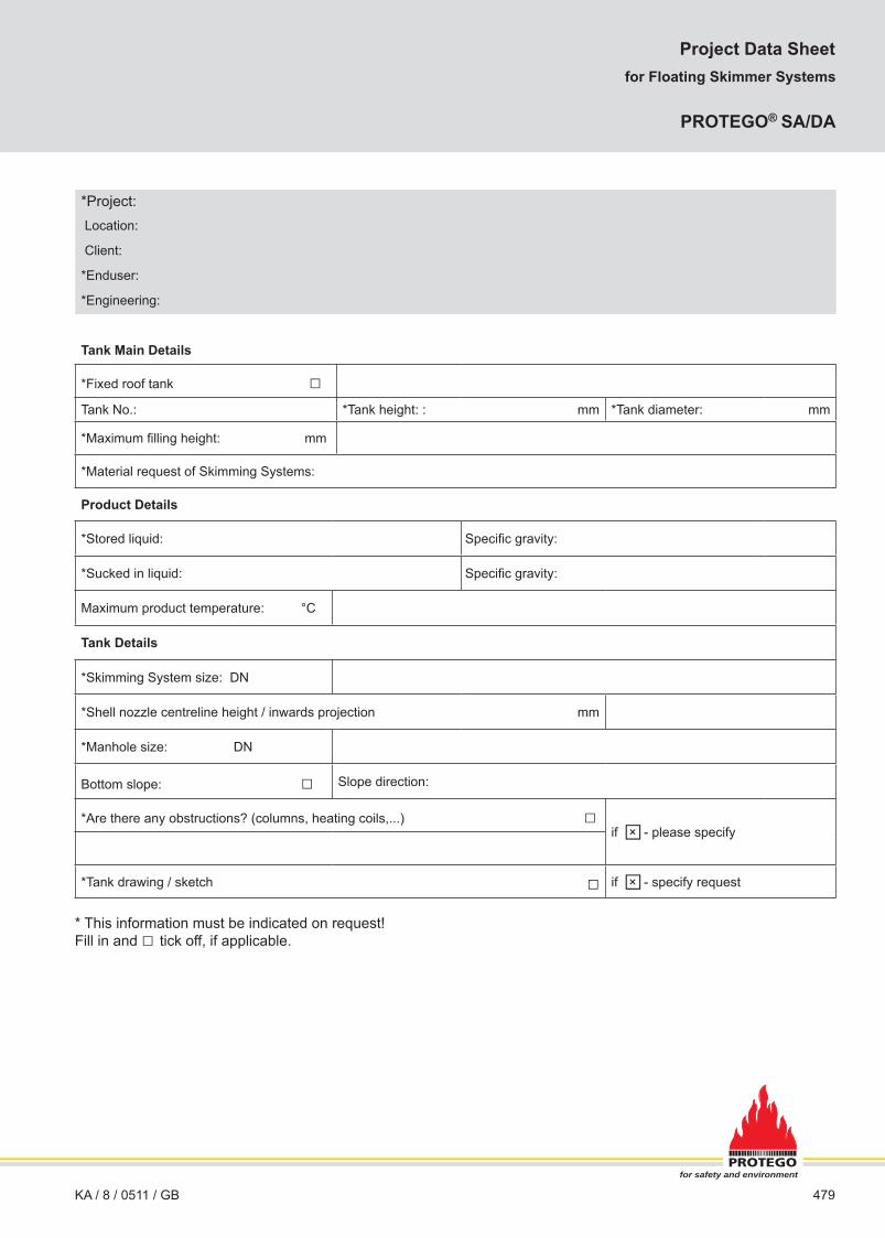
Floating Skimmer System
PROTEGO® SA/DA
All rights and alterations reserved acc. ISO 16016
Function and Description
Fixed roof tanks that store liquids with different density these so-called slop tanks are fi tted with the Floating Skimmer System PROTEGO® SA/DA for separating the phases. The design of the skimmer results from different densities. They are developed to draw off the product with lower specifi c weight from the surface of the stored medium.
Design Types and Specifi cations
PROTEGO® SA/DA Floating Skimmer Systems are designed and sized to suit the individual tank specifi cations and the stored medium as well as customer requirements.
PROTEGO® SA/DA Floating Skimmer Systems are designed for a long life in service in complete medium contact.
We use carbon steel or stainless steel for highly loaded compo-nents or aggressive media.
Solutions are available from 2” to 6” for tanks with fi xed roofs.
Selection and Design
PROTEGO® Floating Skimmer Systems offer experienced tech-nology for a complete solution for the end-user. This includes easy installation and assembly of the system in the tank and full documentation with an arrangement drawing showing the Floating Skimmer System placed in the tank with regards to all internals.
Essential for the design of the PROTEGO® Floating Skimmer Systems is the Heavy Duty Swivel Joint which fulfi ls the require-ment for an in-service installation to avoid high costs of repairs and to extend the tank maintenance to the planned interval.
The Swivel Joint comes with/in
• a sturdy design made of carbon or stainless steel
• maintenance-free greased for a life-time with aviation approved grease
• large sized ball bearings with two races to cover all
side-fl ow forces during operation.
PROTEGO® Floating Skimmer Systems SA/DA are fi tted with a separate skimming fl oat that is just responsible for separat-ing the different phases. The weight of the complete system is fl oated by one or more fl oats.
Floats are always made of stainless steel and are 100 % pres-sure tested.
PROTEGO® Floating Skimmer Systems are „Made in Germany“ and will provide many years of trouble free tank operation.
PROTEGO® SA/DA for fi xed roof tanks PROTEGO® SA/DA with double-bend for fi xed roof tanks
- Active data sheet at www.protego.de
479KA / 8 / 0511 / GB
*Project: Location:
Client:
*Enduser:
*Engineering:
Tank Main Details
*Fixed roof tank □Tank No.: *Tank height: : mm *Tank diameter: mm
*Maximum fi lling height: mm
*Material request of Skimming Systems:
Product Details
*Stored liquid: Specifi c gravity:
*Sucked in liquid: Specifi c gravity:
Maximum product temperature: °C
Tank Details
*Skimming System size: DN
*Shell nozzle centreline height / inwards projection mm
*Manhole size: DN
Bottom slope: □ Slope direction:
*Are there any obstructions? (columns, heating coils,...) □if × - please specify
*Tank drawing / sketch □ if × - specify request
* This information must be indicated on request!Fill in and □ tick off, if applicable.
Project Data Sheetfor Floating Skimmer Systems
PROTEGO® SA/DA
□□
for safety and environment

480 KA / 8 / 0511 / GB
Floating Roof Drainage System with Metal Hose Joints
PROTEGO® SE/K
Function and Description
Floating roof tanks require a drainage system that automati-cally drains the accumulating rainwater off the fl oating roof. PROTEGO® SE/K is a single scissor-pipe-system that works with robust shackle joints. The water is drained by unstressed mounted and pressure resistant metal hoses.
The upper scissor pipe is connected to the roof drain valve and the lower scissor pipe is connected to the bottom pipe. Via the operational opened roof drain valve the water is transfered by the drainage system out of the tank.
Design Types and Specifi cations
PROTEGO® fl oating roof drainage systems are designed and sized to suit the individual tank specifi cations and customer re-quirements.
PROTEGO® fl oating roof drainage systems are designed for a long life in service. We use only carbon steel or stainless steel as the material of construction. For the carbon steel version the joint bearings are made of stainless steel.
Solutions are available from 3” to 8” for fl oating roof tanks with external fl oating roof.
Selection and Design
PROTEGO® Floating Roof Drainage Systems offer experi-enced technology for a complete solution for the end-user. This includes easy installation and assembly and full docu-mentation with an arrangement drawing showing the Floating Roof Drainage System placed in the tank with regards to all internals. The fl exibility of the metal hose is realized by the shakle-boltedjoint. Forces that may occur due to torsion or uneven move-ments of the fl oating roof are absorbed through design and ar-rangement of the joints and thus have no negative effects on the system or metal hoses. The water is drained by metal hoses that are directly connected to the scissor pipes. The drain water does not pass through the actual joints and therefore sealing elements as used for common swivel joint systems are not re-quired.
For stability reasons metal hose joints are made of steel or stain-less steel.
Options upon request:
- Roof drain valve- Bottom pipe- On-site support
All rights and alterations reserved acc. ISO 16016
PROTEGO® Floating Roof Drainage Systems are „Made in Germany“ and will provide many years of trouble free tank operation.
Roof drain valvePROTEGO® D/SR-W
RIM Vent
Bottom pipe
- Active data sheet at www.protego.de

481KA / 8 / 0511 / GB
*Project: Location:
Client:
*Enduser:
*Engineering:
Tank Main Details
*Floating roof tank □Tank No.: *Tank height: : mm *Tank diameter: mm
*Maximum fi lling height: mm
* Material request of Floating Roof Drainage System:
Product Details
*Product stored:
*Specifi c gravity:
Maximum product temperature: °C
Tank Details
*Nominal diameter of drain line: DN
*Shell nozzle centreline height / inwards projection mm
*Manhole size: DN
Bottom slope: □ Slope direction:
*Are there any obstructions? (columns, heating coils,...) □if × - please specify
*Tank drawing / sketch □ if × - please specify
* This information must be indicated on request!Fill in and □ tick off, if applicable.
Project Data Sheetfor Floating Roof Drainage System with Metal Hose Joints
PROTEGO® SE/K
□□
for safety and environment

482 KA / 8 / 0511 / GB
Floating Roof Drainage System with Swivel Joints
PROTEGO® SE/CK
Function and Description
Floating roof tanks require a drainage system that automati-cally drains the accumulating rainwater off the fl oating roof. PROTEGO® SE/CK is a single scissor-pipe-system that works with swivel joints.
The upper scissor pipe is connected to the roof drain valve, the lower scissor pipe is connected to the bottom pipe. Via the op-erational opened roof drain valve the water is transfered by the drainage system out of the tank.
Design Types and Specifi cations
PROTEGO® fl oating roof drainage systems are designed and sized to suit the individual tank specifi cations and customer re-quirements.
PROTEGO® fl oating roof drainage systems are designed for a long life in service. We use carbon steel or stainless steel for highly loaded components or aggressive media.
Solutions are available from DN 80/3” to DN 200/8” for fl oating roof tanks with external fl oating roof.
Selection and Design
PROTEGO® Floating Roof Drainage Systems offer experi-enced technology for a complete solution for the end-user. This includes easy installation and assembly and full docu-mentation with an arrangement drawing showing the Floating Roof Drainage System placed in the tank with regards to all internals. Essential for the design of the PROTEGO® Floating Roof Drainage System is the Heavy Duty Swivel Joint which fulfi ls the requirement for an in-service installation to avoid high costs of repairs and to extend the tank maintenance to the planned interval. The Swivel Joint comes with/in
• a sturdy design made of carbon or stainless steel• maintenance-free greased for a life-time with aviation approved grease• large sized ball bearing with two races to cover all side-fl ow forces during operation.
Options upon request:
- Roof drain valve- Bottom pipes- On-site support
All rights and alterations reserved acc. ISO 16016
PROTEGO® Floating Roof Drainage Systems are „Made in Germany“ and will provide many years of trouble free tank operation.
Roof drain valvePROTEGO® D/SR-W
Bottom pipe
RIM Vent
- Active data sheet at www.protego.de

483KA / 8 / 0511 / GB
*Project: Location:
Client:
*Enduser:
*Engineering:
Tank Main Details
*Floating roof tank □Tank No.: *Tank height: : mm *Tank diameter: mm
*Maximum fi lling height: mm
* Material request of Floating Roof Drainage System:
Product Details
*Product stored:
*Specifi c gravity:
Maximum product temperature: °C
Tank Details
*Nominal diameter of drain line: DN
*Shell nozzle centreline height / inwards projection mm
*Manhole size: DN
Bottom slope: □ Slope direction:
*Are there any obstructions? (columns, heating coils,...) □if × - please specify
*Tank drawing / sketch □ if × - please specify
* This information must be indicated on request!Fill in and □ tick off, if applicable.
□□
Project Data Sheetfor Floating Roof Drainage System with Swivel Joints
PROTEGO® SE/CK
for safety and environment

484
Function and Description
The PROTEGO® roof drain valves D/SR or D/SR-W function like collection bowls and pass the collected rain water from the fl oating roof through the scissor pipes of a PROTEGO® fl oating roof drainage system, such as SE/K or SE/CK, into the sewage water system.
Under normal operating conditions the roof drain valve is open. In case of any leakage the non-return valve prevents the stored medium from escaping to the fl oating roof. The inlet screen pro-tects the roof drain valve from any dirt, leaves or nesting birds.
Design Types and Specifi cations
Two designs are available:
Roof drain valve with vertical connection
Roof drain valve with horizontal connection
D/SR
D/SR-W
As an option a special design of the roof drain valve is available with protection against unauthorized closing of the quick-action shut-off (S).
Table 1: Dimensions D/SR Dimensions in mm / inchesDN 80 / 2" 100 / 4" 150 / 6"a 550 / 21.65 600 / 23.62 650 / 25.59b 490 / 19.29 540 / 21.26 590 / 23.23c 450 / 17.72 500 / 19.69 550 / 21.65d 240 / 9.45 280 / 11.02 330 / 12.99e 490 / 19.29 490 / 19.29 490 / 19.29f 160 / 6.3 180 / 7.09 240 / 9.45g 200 / 7.87 220 / 8.66 285 / 11.22h M 16 M 16 M 20
Table 2: Dimensions D/SR-W Dimensions in mm / inchesDN 80 / 2" 100 / 4" 150 / 6"a 550 / 21.65 600 / 23.62 650 / 25.59b 490 / 19.29 540 / 21.26 590 / 23.23c 450 / 17.72 500 / 19.69 550 / 21.65d 205 / 8.07 250 / 9.84 320 / 12.6e 490 / 19.29 490 / 19.29 490 / 19.29f 285 / 11.22 320 / 12.6 350 / 13.78g 150 / 5.91 180 / 7.09 225 / 8.86
All rights and alterations reserved acc. ISO 16016KA / 8 / 0511 / GB
Roof Drain Valves
PROTEGO® D/SR and D/SR-W
D/SR-W
ed
Ø a
Ø b
DN DN
g
Ø c
f f
D/SR
e
Ø a
Ø b
d
DN
Ø f
Ø g
Ø c
h
S
S
- Active data sheet at www.protego.de

485
Table 3: Material selectionDesign A BHousing Steel Stainless SteelNon-return valve Red Brass Red BrassValve disc Steel Stainless SteelQuick-action shut-off Steel Stainless SteelGasket PUR PUR
The device must have suffi cient corrosion resistance with re-gards to the stored media. If necessary, designs in special stain-less steel quality should be selected.
Flange Connection Type
In type PROTEGO® D/SR the housing bottom is equipped with a loose fl ange with threaded holes according to EN 1092-1 or DIN DIN 2501, PN 16, or optionally according to any other inter-national standard.
In the standard model of PROTEGO® D/SR-W the housing is equipped with a lateral fl ange connection to EN 1092-1 or DIN 2501, PN 16. Optionally, the connecting fl anges can be made according to any other international standard. An additional fl ange connection is available.
Selection and Design
The specifi ed maximum rainfall is required to determine the required nominal size. Alternatively, the connection size of the roof drain valve corresponds with the existing nominal dimen-sion of the fl oating roof drainage system. Roof drain valves with 2 or 3 non-return valves are available as an option.
Necessary Data for Specifi cation
Maximum rainfall to be drained off (m³/h or CFH)
Material of fl oating roof
Connection size of the fl oating roof drainage system DN (mm or inches)
Design of fl oating roof drainage system
KA / 8 / 0511 / GB
Application Examples
PROTEGO® roof drain valve type D/SR in combination with Floating roof drainage system PROTEGO® SE/CK
PROTEGO® roof drain valve type D/SR-W in combination with Floating roof drainage system PROTEGO® SE/K.
for safety and environment
D/SR
D/SR-W
RIM Vent
RIM Vent

486
Vent Valve, Lift-actuated
PROTEGO® AL/DK and PROTEGO® AL 200
Function and Description
PROTEGO® lift-actuated vent valves type AL/DK provide au-tomatic venting of fl oating roof tanks when the fl oating roof is lowered on its supports and the tank is either fi nally drained or refi lled. When the fl oating roof is in its lowest position the valve is forced to open through lift actuation and this prevents unac-ceptable vacuum during fi nal draining or unacceptable pressure during refi lling.
In general the device consists of a housing (1) with sheet-metal panel to be welded on the fl oating roof, two or four connection nozzles (2) for installation of vent caps, cover (3), lift (4) includ-ing valve pallet (5), lift pipe (6) and the condensate drain valve (7) which can be fl ame transmission proof if required. A fl at gas-ket is attached to the valve pallet (5) to provide sealing. The cover (3) is sealed by a sealing cord (8).
In general the device PROTEGO® AL 200 consists of a housing (1) with sheet-metal panel to be welded on the fl oating roof as well as the valve seat (2), lift (3) including valve pallet (4) and lift pipe (5). A fl at gasket (6) which provides sealing.
KA / 8 / 0412 / GB
As the lowest position of the fl oating roof varies for operation and assembly specify the dimensions h1 and h2:
h1: Distance between lower edge of sheet-metal panel (or mounting fl ange) and tank bottom in lowest position of fl oating roof (operating position with an empty tank).
h2: Distance between fl oating roof in lifted maintenance position and height of fl oating roof in fully lowered operating position, if the tank is empty.
If the fl oating roof supports are changed from operating position to maintenance position the lift has to be lengthened as well. This is done with an adjustable locking pin that is secured with a bolt.
The valve is not fl ame transmission proof.
A hazard analysis (which considers the material selection and function of the device) shows that the device doesn’t have any potential sources of ignition. Therefore they are not subject to the European Explosion Protection Directive 94/9/EC when used in explosive atmosphere.
All rights and alterations reserved acc. ISO 16016
e
Ø a
b
f
DN
Ø d
DN
NG
c
h 1
h 2
b
2
1
3
6
4
5
7
8
h 2
h 1
AL/DK AL 200
2
4
3
5
1
6
Floating roof
Bottom of the tank
Floating roof
Bottom of the tank
Dimensions in mm / inches
720
/ 28.
35
Ø 308 / 12.13
Ø 450 /17.72
NG 200 / 8“
- Active data sheet at www.protego.de

487
Designs and Specifi cations
Table 1: Dimensions for AL/DKNG 200 / 8" 200 / 8" 200 / 8"DN 100 / 4" 150 / 6" 200 / 8"a 350 / 13.78 350 / 13.78 350 / 13.78b 465 /18.31 465 / 18.31 515 / 20.28c 870 / 34.25 870 / 34.25 870 / 34.25d 450 / 17.72 450 / 17.72 450 / 17.72e 385 / 15.16 385 / 15.16 415 / 16.34f 420 / 16.54 285 / 11.22 370 / 14.57
Dimensions in mm / inches
Table 2: MaterialHousing Steel
special materials upon request
Valve guide Stainless SteelGasket FPM
Table 3: Flange connection type DN2EN 1092-1, Form B1 or DIN 2501, Form C, PN 16; from DN 200 PN 10
EN or DIN
ANSI 150 lbs RFSF ANSI
other types upon request.
Selection and Design
The required quantity and nominal size DN will be defi ned based on the calculated fl ow rate from the thermal venting and pump rate in lowest fl oating roof position (Nm³/h or CFH) and based on the maximum acceptable tank pressure pT (mbar / inch W.C.) according to the fl ow capacity charts. Special models are avail-able on request.Flow rates and pressure losses of vent caps PROTEGO® BE/HRor PROTEGO® LH/AD have additionally to be taken into account according to the appropriate charts in the relevant data sheets or operating instructions.Lift-actuated vent valves PROTEGO® AL 200 can be applied in case just venting is required.
Necessary Data for Specifi cation
Stored productTank diameter (m or ft) Tank height (m or ft)Support height h1 (operating position with empty tank)Support height h2 (lifted assembly position)Maximum allowable tank pressure pT (mbar or inch W.C.)Pump rate (m³/h or CFH)
KA / 8 / 0412 / GB
Application Examples for PROTEGO® AL/DK
Lift-actuated vent valves of type PROTEGO® AL/DK can be combined with vent caps type BE/HR which are defl agration proof and resistant against endurance burning. This ensures fl a-me transmission proof ventilation.
If resistance against endurance burning is not required the val-ves can alternatively be combined with PROTEGO® defl agrati-on proof devices type PROTEGO® LH/AD. The applicable data sheets are available in volume 2 “Defl agration Flame Arresters, end-of-line and Vent Caps”.
Application Examples for PROTEGO® AL 200
PROTEGO® AL 200 for fi xed roof storage tanks with internal fl oating roof.
for safety and environment
BE/HR
LH/AD
RIM vent
RIM Vent withfl ame arrester
RIM Vent withfl ame arrester

488
AL/DK
pr
essu
re [m
bar]
fl ow rate V. [m³/h] 1261-L
airfl ow in thousands of CFH
pr
essu
re -
inch
W.C
.
Flow Capacity Charts
PROTEGO® AL/DK and PROTEGO® AL 200
Vent Valve, Lift-actuated
KA / 8 / 0412 / GBAll rights and alterations reserved acc. ISO 16016
AL 200
pr
essu
re [m
bar]
fl ow rate V. [m³/h] 2804-L
airfl ow in thousands of CFH
pr
essu
re -
inch
W.C
.
The fl ow capacity charts have been determined with a calibrated and TÜV certifi ed fl ow capacity test rig.Volume fl ow V
. in [m³/h] and CFH refer to the standard reference conditions of air ISO 6358 (20°C, 1bar).
Conversion to other densities and temperatures refer to Vol. 1: “Technical Fundamentals”.
- Active data sheet at www.protego.de

489
Notes:
for safety and environment
490 KA / 8 / 0412 / GB
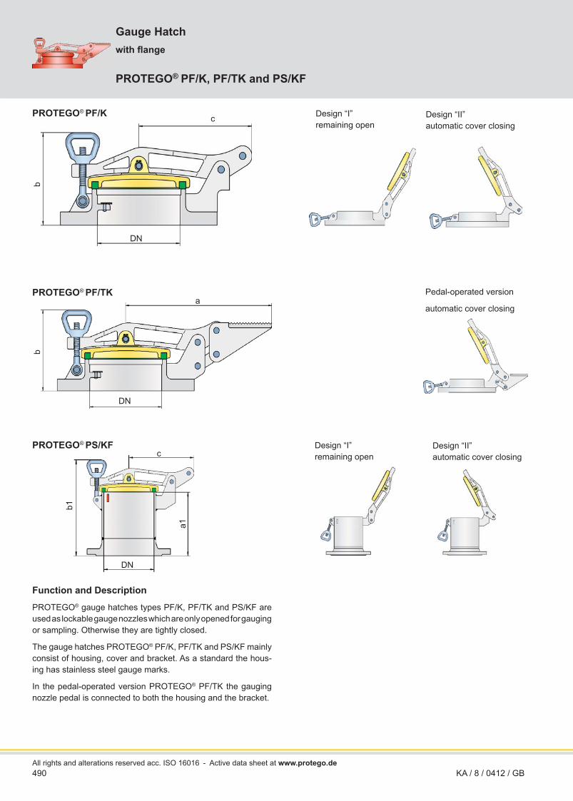
Gauge Hatch
PROTEGO® PF/K, PF/TK and PS/KF
Function and Description
PROTEGO® gauge hatches types PF/K, PF/TK and PS/KF are used as lockable gauge nozzles which are only opened for gauging or sampling. Otherwise they are tightly closed.
The gauge hatches PROTEGO® PF/K, PF/TK and PS/KF mainly consist of housing, cover and bracket. As a standard the hous-ing has stainless steel gauge marks.
In the pedal-operated version PROTEGO® PF/TK the gauging nozzle pedal is connected to both the housing and the bracket.
All rights and alterations reserved acc. ISO 16016
with fl ange b
a
DN
DN
b
c
DN
b1
a1
c
Design “I” remaining open
Pedal-operated version
automatic cover closing
Design “II” automatic cover closing
PROTEGO® PF/K
PROTEGO® PF/TK
PROTEGO® PS/KF Design “I” remaining open
Design “II” automatic cover closing
- Active data sheet at www.protego.de

491KA / 8 / 0412 / GB
Design Types and Specifi cationsDepending on the intended use the following designs are available:
Gauge hatch with fl ange
Gauge hatch with fl ange and pedal
Gauge hatch with fl ange nozzle
PF/K design I and II„I“ : remaining open„II“ : automatic cover closing
PF/TK automatic cover closing
PS/KF design I and II„I“ : remaining open„II“ : automatic cover closing
Gauge hatches for welding to the tank are available as types PROTEGO® PS/K and PS/TK. A separate data sheet is available.
Table 1: Dimensions Dimensions in mm / inchesDN 100 / 4" 150 / 6" 200 / 8"a 260 / 10.24 305 / 12.01 335 / 13.19b 150 / 5.91 155 / 6.10 175 / 6.89c 160 / 6.30 205 / 8.07 235 / 9.25
a1 225 / 8.86 265 / 10.43 300 / 11.81b1 315 / 12.40 360 / 14.17 405 / 15.94
The nominal size depends on the dimensions of the gauging and sampling device.
Table 2: Material selectionDesign A B C DHousing Ductile Iron* Stainless Steel Aluminium Steel
Cover Ductile Iron* Stainless Steel AluminiumStainless Steel** Steel
The combination of steel and aluminium in explosive environ-ments is prohibited due to ignition danger.* only for PF/K and PF/TK** only for PF/TK-100
Flange Connection Type
The fl ange connection is to EN 1092-1, Form A or DIN 2501, Form B, PN 16; DN 200 PN10. Optionally, the connecting fl ange can be made according to any international standard.
Necessary Data for Specifi cation
Stored productTank materialTank nozzle DN (mm or inches)
Application Examples
Gauge Hatches can for instance be used in combination with the manual gauge devices type PROTEGO® H/P or with the gau-ging and sampling device PROTEGO® VP/HK.
Gauge Hatches can be applied on tanks with fl oating roof.
for safety and environment
PF/TK
PF/KRIM Vent
492 KA / 8 / 0412 / GB
Design Types and Specifi cationsDepending on the intended use the following designs are available:
Gauge hatch with welding
nozzle
Gauge hatch with welding
nozzle and pedal
PS/K design I and II„I“ : remaining open„II“ : automatic cover closing
PS/TK automatic cover closing
Gauge hatches with fl ange are available as type PROTEGO® PF/K, PF/TK and PS/KF. A separate data sheet is available.
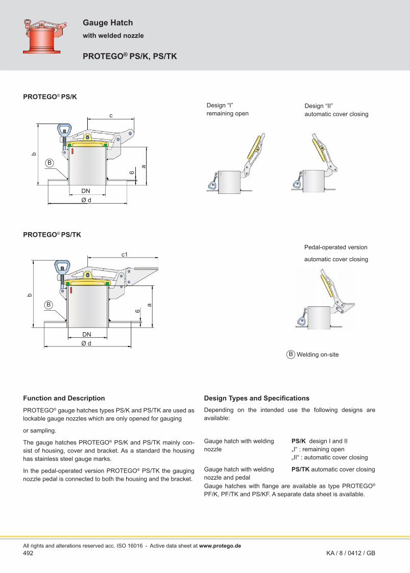
Gauge Hatch
PROTEGO® PS/K, PS/TK
Function and Description
PROTEGO® gauge hatches types PS/K and PS/TK are used as lockable gauge nozzles which are only opened for gauging
or sampling.
The gauge hatches PROTEGO® PS/K and PS/TK mainly con-sist of housing, cover and bracket. As a standard the housing has stainless steel gauge marks.
In the pedal-operated version PROTEGO® PS/TK the gauging nozzle pedal is connected to both the housing and the bracket.
All rights and alterations reserved acc. ISO 16016
Welding on-site
with welded nozzleb
DNØ d
a
6
c1
DN
b
c
a
6
Ø d
B
B
B
Design “I” remaining open
Design “II” automatic cover closing
Pedal-operated version
automatic cover closing
PROTEGO® PS/K
PROTEGO® PS/TK
- Active data sheet at www.protego.de

493KA / 8 / 0412 / GB
Table 1: Dimensions Dimensions in mm / inchesDN 100 / 4" 150 / 6" 200 / 8"a 175 / 6.89 225 / 8.86 250 / 9.84b 265 / 10.43 320 / 12.60 355 / 13.98c 160 / 6.30 205 / 8.07 235 / 9.25
c1 260 / 10.24 305 / 12.01 335 / 13.19d 275 / 10.83 350 / 13.78 450 / 17.72
The nominal size depends on the dimensions of the gauging and sampling device.
Table 2: Material selectionDesign A BHousing Steel Stainless Steel*Cover Ductile Iron Stainless Steel*
* only for PS/K
Flange Connection Type
The fl ange connection is to EN 1092-1, Form A or DIN 2501, Form B, PN 16; DN 200 PN10. Optionally, the connecting fl ange can be made according to any international standard.
Necessary Data for Specifi cation
Stored product
Tank material
Tank nozzle DN (mm or inches)
Application Examples
Gauge Hatches can for instance be used in combination with the manual gauge devices type PROTEGO® H/P or with the gau-ging and sampling device PROTEGO® VP/HK.
Gauge Hatches can be welded on tanks with fl oating roof.
for safety and environment
PS/K
PS/K
RIM Vent

494 KA / 8 / 0512 / GB
DN 40 / 1½" and 50 / 2"
Gauging Pipedefl agration proof
PROTEGO® PU-IIA
Function and Description
The defl agration proof gauging pipes with integrated fl ame ar-resters type PROTEGO® PU are used for explosion-proof gaug-ing of tank contents.
The gauging pipes of type PROTEGO® PU consist of insert pipe (1) with fl ame arresters (2) – equipped with FLAMEFILTER® (3) – connecting pipe (4), bushing (5) to be welded in the nozzle cover and cap (6). The number of fl ame arresters depends on the length of the gauging pipe. Please note the maximum di-mension of 1.2 m / 3.94 ft for measure b and 4.1 m / 13.45 ft for measure c.
In normal operation the gauging pipe is closed with the cap. It is opened only for tank content gauging.
Type PROTEGO® PU ensures fl ame transmission protection against atmospheric defl agrations or in-line defl agrations of gas/air mixtures or product vapour/air mixtures of substances from explosion group IIA (MESG > 0.9 mm, NEC group D) in all ranges of fl ammable concentrations up to a service temperature of +60°C / 140°F.
This device is type approved and tested according to the Euro-pean Standard EN 12874 – Flame Arresters – as a protective system according to European Directive 94/9/EC – equipment intended for use in potentially explosiv atmospheres. EC-Type Examination Certifi cates issued by a European notifi ed body are available. Examination certifi cates from other approval authori-ties are available on request.
Design Types and Specifi cations
Table 1: Dimensions Dimensions in mm / inchesThe measures a, b, y must be given with the order
DN minimum size d25 / 1" 150 / 5.91
32 / 1¼" 150 / 5.91 40 / 1½" 200 / 7.87
50 / 2" 200 / 7.87
All rights and alterations reserved acc. ISO 16016
Ø d
c
ba
DN
y
6
2
3
5
4
1
Design A Design B
- Active data sheet at www.protego.de

495KA / 8 / 0512 / GB
Table 2: Material selectionDesign A BGauging pipe Steel Stainless SteelWeld-in bushing Steel Stainless SteelCap Brass Stainless SteelFLAMEFILTER® cage Steel Stainless SteelFLAMEFILTER® Stainless Steel Stainless Steel
In design A the connecting pipe is equipped with reducing piece and blind cap – each with integrated sealing and chain. In de-sign B the connecting pipe is closed with a hexagon cap con-nected to the retainer ring via chain and wire hoop.
Table 3: Explosion group
MESG Expl. Gr. (IEC/CEN)
Gas Group (NEC)
> 0,90 mm IIA D
Special approvals upon request
Selection and Design
Select the required nominal sizes based on the gauging equip-ment size or nominal sizes of the connecting nozzle. Specify measures a, b and y for the defi nition of the quantity of inte-grated fl ame arresters.
Necessary Data for Specifi cationStorage product
Tank diameter (m or ft)
Tank nozzle height y (m or ft)
Length a (m or ft)
Length b (m or ft), max. 1.2 m / 3.94 ft
Please note the maximum length of 4.1 m / 13.45 ft formeasure c
Gauging pipe diameter DN (mm or inches)
Application Example
The gauging pipes of type PROTEGO® PU mainly serve for tank gauging in horizontal tanks using fuel dip stick or manual gaug-ing device e.g. of type PROTEGO® HP.
for safety and environment

496 KA / 8 / 0412 / GB
Gauging and Sampling Pipeverifi able
PROTEGO® PR/0
Function and Description
The gauging and sampling pipes type PROTEGO® PR/0 are used for gauging of tank contents in horizontal or vertical tanks. They can be used in combination with other devices as for instance PROTEGO® VP/HK, PROTEGO® PS/E as well as PROTEGO® PG/H. The gauging and sampling pipes PROTEGO® PR/0 consist of the gauging and sampling pipe (1), the cap (2) with gasket and the gauging table (3).
All rights and alterations reserved acc. ISO 16016
In normal operation the gauging pipe is closed with the cap. It is opened only for tank content gauging. PROTEGO® PR/0 is not fl ame transmission proof and therefore special safety measures have to be implemented in order to avoid fl ame transmission into the tank caused by external igni-tion sources.
Version 2Alternatively to gauging table (from DN 80 / 3“) design with per-forated bottom (DN 25 / 1“ to DN 150 / 6“)
Version 1Design with fl ange for combination with a gauging and sampling device (from DN 100 /4”)
job site welding
Ø a
c
ed
DN
Ø b
2
3
1
120°
120°
fB B
B
- Active data sheet at www.protego.de

497KA / 8 / 0412 / GB
Design Types and Specifi cations
Table 1: DimensionsDimensions in mm / inchesThe measures c, d, e, f must be given with the order
DN a b number of hole lines
25 / 1" 32 - 1 32 / 1¼" 40 - 1
50 / 2" 80 - 280 / 3" 100 305 3
100 / 4" 150 / 5.91 305 3150 / 6" 200 / 7.87 375 3
Table 2: Material selectionDesign A BGauging pipe Steel Stainless SteelGauge plate Steel Stainless SteelCap Brass Stainless Steel
For combination with other gauging device design 1 with wel-ding neck fl ange is available (from DN 100 / 4”).Instead of the Gauging Table PROTEGO® PT/S a perforated bottom can be chosen alternatively (design 2).
Selection and Design
Select the required nominal sizes based on the gauging equip-ment size or nominal sizes of the connecting nozzle. Specify measures c, d e, and f must be specifi ed with the order and necessary for the interpretation.
The device must be suffi ciently resistant to corrosion through product vapour/air mixtures. If necessary, designs in special stainless steel quality should be selected.
Necessary Data for Specifi cationStorage product
Tank nozzle diameter DN
Tank inner diameter c (m or ft) for horizontal tanks
Tank height c (mm or inches) for standing tanks
Length d (mm or inches)
Length e (mm or inches)
stud length f (mm or inches)
Application Examples
Gauging and Sampling Pipe PROTEGO® PR/0 with perforated bottom for the horizontal tank.
Gauging and Sampling Pipe PROTEGO® PR/0 with gauging table PROTEGO® PT/S as well as Gauging Nozzle PROTEGO® PS/KF for a vertical tank.
Also sampling with a suitable Sampling Pot PROTEGO® PG/H is possible. Information about gauging and sampling device are available in a separate catalogue sheet.
for safety and environment
PS/KF

498 KA / 8 / 0511 / GB
Gauging and Sampling Device
PROTEGO® VP/HK with PS/E and PG/H
with accessories
All rights and alterations reserved acc. ISO 16016
f
Ø c
g
Ø a
DN
eb
d
2
3
1 Portable manual gauging and sampling device PROTEGO® VP/HK
Dimensions in mm / inches
Sampling pot PROTEGO® PG/H capacity: 1 liter /0.22 gal (UK)
(2 liters / 0.44 gal (UK) capacity =measures in brackets)
Gauging nozzle PROTEGO® PS/E
1015
/ 39
.96
150 / 5.91
Ø 95 / 3.74
260
/ 10.
24 (4
40 /
17.3
2)
280
/ 11.
02 (4
60 /
18.1
1)
325
/ 12.
80 (4
75 /
18.7
0)
- Active data sheet at www.protego.de

499KA / 8 / 0511 / GB
Function and Description
The PROTEGO® gauging and sampling assembly consists of the manual gauging and sampling device PROTEGO® VP/HK (1), the gauging nozzle PROTEGO® PS/E (2), the gauging pipe PROTEGO® PR/0, the gauge plate PROTEGO® PT/S and the sampling pot PG/H (3). This assembly serves for gauging (deter-mination of the liquid level) and sampling in horizontal or vertical aboveground tanks which store non-fl ammable or – if equipped appropriately – fl ammable liquids, this device may also be used for storage tanks approved by customs.
The portable gauging and sampling device PROTEGO® VP/HK is attached by a clamp to the fi xing rod of the gauging nozzle. The millimeter-scale measuring tape – black anodized – is cali-brated by customs.
The gauging pipe PROTEGO® PR/ 0 is made of an insert- pipe with holes. The slip-on fl ange is included in the shipment and has to be welded on during on-site assembly.
The gauging nozzle with hinged cover and clip-lock PROTEGO® PS/E is attached to the counter-fl ange of the gauging and sampling pipe. The locking nozzle has the fi xing rod attached for connecting the gauging and sampling device PROTEGO® VP/HK.
The sampling constructed from stainless steel with conductive plastic caps pot PROTEGO® PG/H consists of housing with me-tallic sealing valve discs and snap-hook. Specify the required capacity (1 l or 2 l / 0.22 gal (UK) or 0.44 gal (UK)).
Design Types and Specifi cations
The assembly can be ordered either as complete unit or in individual devices. Please specify the nominal diameters DN for gauging nozzle and gauging pipe.
1) Manual gauging and sampling device VP/HK including
2) Gauging nozzle PS/E, DN (mm or inches)
3) Gauging pipe PR/0, DN (mm or inches)
Gauge plate PT/S
Sampling pot PG/H
Table 1: Dimensions Dimensions in mm / inchesDN a b c e f g
100 / 4" 150 / 5.91
150 / 5.91
305 / 12.01
300 / 11.81
640 / 25.20
280 / 11.02
150 / 6" 200 / 7.87
150 / 5.91
375 / 14.76
300 / 11.81
640 / 25.20
280 / 11.02
Measure d must be given with the order
Table 2: Material selection for VP/HKMeasuring tape Stainless SteelLowering weight Stainless SteelCrank handle AluminiumFrame AluminiumGauging nozzle PS/E Steel or Stainless Steel Gauging pipe PR/0 Steel or Stainless Steel Gauging plate PT/S Steel or Stainless Steel Sampling pot PG/H Stainless Steel
Selection and Design
The materials of the tank and storage medium determine the basic materials to be selected.
Necessary Data for Specifi cation
Specify the tank dimensions for the lengths of tape and gauging pipe PROTEGO® PR/0.
Specify the required capacity for the sampling pot PROTEGO® PG/H(1 l or 2 l / 0.22 gal (UK) or 0.44 gal (UK)).
Application Example
for safety and environment

500 KA / 8 / 0412 / GBAll rights and alterations reserved acc. ISO 16016
Function and Description
The gastight Gauging and Sampling Device PROTEGO® VP/G-II-100 in combination with a Sampling Pot PROTEGO® PG/H allows for sampling of the stored product without opening the tank to the atmosphere.
This device consists of the rotary table with connecting nozzle DN 100 or ANSI 4“, the operating button with crank for the mea-suring tape as well as the inspection glass top for monitoring the sampling level.
The rotary table has to be turned through 180° by a rotary table axis from resting position into operating position or the other way round. In resting position (fi gure 1) – measuring tape is wound up – the sampling pot can be mounted or removed.
Sampling takes place in operating position (fi gure 2). Where the measuring tape is manually lowered to the required position and rewound with the crank.
The devices are designed and tested according to the European Standards EN 1127-1, EN 13463-1 and EN 13463-5 as device according to European Directive 94/9/EG. EC-Type Examinati-on Certifi cates issued by a European notifi ed body are available. The scope applies to atmospheric conditions. That is a max. acceptable operating pressure of 1.1 bar absolute and a max. acceptable operating temperature of 60 °C.
Parts of this device being located in zone 0 comply with the re-quirements of non-electrical devices in ignition protection type c (protection by sage construction) of device group II, category 1G. They comply to the requirements for application in explosi-on group IIA and IIB and temperature category T1 to T6. Parts being located in zone 1 comply to device group II, category 2G.
Sampling Device, gastight
PROTEGO® VP/G-II-100 and PG/H
Dimensions in mm / inches
with accessories10
95 /
43.1
1
300 / 11.81
DN 100 / 4“
345 / 13.58
Figure 2Sampling in operating position
Figure 1Removal of the pot in resting position
Sampling pot PROTEGO® PG/H capacity: 1 liter /0.22 gal (UK)
(2 liters / 0.44 gal (UK) capacity =measures in brackets)
Ø 95
260
(440
)28
0 (4
60)
325
(475
)
- Active data sheet at www.protego.de

501KA / 8 / 0412 / GB
Flange Connection Type
Table 3: Flange connection type DN2EN 1092-1, Form B1 or DIN 2501, Form C, PN 16
EN or DIN
ANSI 150 lbs RFSF ANSI
Necessary Data for Specifi cation
Stored medium
Service temperature (°C or °F)
Operating pressure (bar or psi)
Tank material
Tank nozzle DN1 (mm or inches)
Application Example
Gastight sampling on a tank meaning sampling without direct contact between gas zone and atmosphere.
for safety and environment

502 KA / 8 / 0511 / GBAll rights and alterations reserved acc. ISO 16016
Level Indicator
PROTEGO® GS/F-IIB3
defl agration proof
Function and Description
The Level Indicators PROTEGO® GS/F indicate the liquid level inside the tank on a graduated level indicator that is placed out-side at the tank.During fi lling and emptying the tank the fl oat moves depending on the liquid level and via the operating rope activates the indi-cator weight. Depending on the changing liquid level the level indication is displayed outside on the graduated level indicator. As standard the level is indicated reverse to the liquid level. Therefore the fi lling level “0” is placed on the upper end of the scale.In case of atmospheric defl agration (outside explosions) fl ame transmission into the tank is prevented due to fl ame transmissi-on proof gap bushings. Therefore, the PROTEGO® GS/F-IIB3 is explosion (defl agration) proof zone 0.
According to the type examination certifi cates, the liquid indica-tors PROTEGO® GS/F guarantee for fl ame transmission protec-tion against atmospheric defl agration of gas or product / air mix-tures of explosion group IIB3. The scope applies to atmospheric conditions. That is a max. acceptable operating pressure of 1.1 bar and a max. acceptable operating temperature of 60 °C.Test certifi cates and EC-Type Examination Certifi cates issued by a European notifi ed body are available
DN50, PN102“ ANSI 150 lbs
Detailed scale available upon request
- Active data sheet at www.protego.de

503KA / 8 / 0511 / GB
Design Types and Specifi cations
Following designs are available:
Level Indicator, standard design
Level Indicator, indication equal level
Level Indicator, half indication
GS/F - IIB3
GS/F - IIB3 (N)
GS/F - IIB3 (H)
Table 1: Material selection for housing groupDesign A BRoller box Cast Iron Stainless SteelDefl ection pulleys Stainless Steel Stainless SteelOperating rope Stainless Steel Stainless SteelBrackets Steel Stainless SteelIndicator scale Polystyrene Polystyrene
The material of the connection fl ange has to be compatible to the material of the plant component.
Table 2: Material selection for fl oatDesign A Bfl oat Steel Stainless Steelguide rope Steel, galvanized Stainless Steel
Table 3: Flange connection typeEN 1092-1, Form B1 or DIN 2501, Form C, PN 16
EN or DIN
ANSI 150 lbs RFSF ANSI
Table 4: Selection of the explosion group
MESG Expl. Gr. (IEC/CEN)
Gas Group (NEC)
≥ 0,65 mm IIB3 C
Selection and Design
Suffi cient corrosion resistance with regard to the stored media must be considered. The design of the level indicators depends on the construction of the tank design
Necessary Data for Specifi cation
Stored product
Tank material
Tank diameter (m)
Tank height (m)
for safety and environment

504 KA / 8 / 0412 / GB
Sampling and Air Bleed Valvedefl agration proof
PROTEGO® ZE/WU
Standard design up to PN 25
Function and Description
The PROTEGO® ZE/WU sampling and air bleed valve is used for fl ame transmission proof venting of pipelines and equipment that transports or processes fl ammable liquids, and for taking liquid samples.The valve incorporates an end-of-line defl agration fl amearrester. Should the gas/air mixtures or product vapour/air mix-tures ignite during venting, the valve prevents fl ash back into the system to be protected.The sampling and air bleed valve PROTEGO® ZE/WU consists of the threaded angle valve in pressure stage PN25 (1) with hand wheel as standard design and female threaded connec-tion (pipe thread G½“up to G1“) and the fl ame arrester (2) with cover (3).As an optional elbow fi tting (4) is available as outlet for sam-pling. The fl ame arrester (2) consists of the fl ame arrester cage with FLAMEFILTER®.The valve opens manually with the hand wheel. For sampling, a suitable container is required.The simple and sturdy design makes it suitable for nearly all fl ammable liquids. This device can be installed in any position.Flame transmission protection is guaranteed against atmos-pheric defl agrations of gas/air mixtures or product vapour/air mixtures of explosion groups up to IIB (NEC group D to C) up to a service temperature of +60°C / 140°F and an absolute operat-ing pressure up to 1.1 bar / 15.9 psi.Type-approved according to ATEX Directive 94/9/EC and EN ISO 16852 as well as other international standards.
Designs and Specifi cations
There are two designs available:
Sampling and air bleed valve, standard design
Sampling and air bleed valve with elbow
ZE/WU - 1
ZE/WU - 2
Special designs for higher pressures are available
Optionally available with fl ange connection (see fi gure)
All rights and alterations reserved acc. ISO 16016
* Position of drilling holes on fl ange con-nection as well as thickness upon request for size DN15 / ½“, DN20 / ¾“, DN25 / 1“,DN32 / 1¼“, DN40 / 1½“ and pressure nomi-nal PN25/40 resp. PN100 available.
d
DN
Ø c
a
b
2
3
1
Ø c
a
DN
b
e
f
4
ZE/WU-1
ZE/WU-2
nfDn
DN*
- Active data sheet at www.protego.de

505KA / 8 / 0412 / GB
Table 1: Dimensions Dimensions in mm / inchesDN a b Ø c d e f
15 / G½" 40 /1.57
140 /5.51
70 /2.76
80 /3.15
96 /3.78
67 /2.64
20 / G¾" 50 /1.97
165 /6.50
85 /3.35
80 /3.15
89 /3.50
67 /2.64
25 / G1" 65 /2.56
200 /7.87
100 /3.94
95 /3.74
104 /4.09
67 /2.64
Table 2: Explosion group
MESG Expl. Gr. (IEC/CEN)
Gas Group (NEC)
≥ 0,50 mm IIB C
Table 3: MaterialDesign AThreaded angle valve Stainless SteelElbow Stainless SteelCover Stainless SteelFLAMEFILTER® Stainless Steel
The valve must be suffi ciently resistant to corrosion through the gas/air mixtures or product vapor/air mixtures. This applies mainly to the FLAMEFILTER®.
Table 4: Type of connectionPipe thread DIN ISO 228 T1 DIN
Order example
Materials and chemical resistance: Technical information upon request
ZE/WU – ¾" A–1 –
—— Type
—— Nominal size
—— Material
Tab. 1 —Tab. 3 —
—— 1 or 2
ZE/WU – ––
Design
for safety and environment

506 KA / 8 / 0412 / GB
Condensate Drain Valvedefl agration proof
PROTEGO® ZE/TK
Function and Description
The PROTEGO® ZE/TK condensate drain valve is used for fl ame transmission proof condensate drainage of devices or plant equipment (e.g. tanks, pipelines, etc.) where fl ammable liquids may condense and therefore fl ammable product vapour/air mixtures could develop. Furthermore the drain valves can be used for the venting of tanks, parts of plants and lines that trans-port or process fl ammable liquids. The drain valve incorporates an end-of-line defl agration fl ame arrester.
The condensate drain valve PROTEGO® ZE/TK consists of the ball valve (1) with hand lever (2) and female threaded connec-tion (e.g. pipe thread G½" up to G1") and the fl ame arrester (3) with cover (4).
As an option a elbow fi tting (5) is available as outlet.
The fl ame arrester (3) consists of fl ame arrester cage and FLAMEFILTER®.
The ball valve is opened with the hand lever. When draining condensate use a suitable container. When draining fl ammable and/or toxic products observe the appropriate safety provisions.
The simple and sturdy design it is suitable for nearly all fl am-mable liquids, and can be installed in any position.Flame transmission protection is guaranteed against atmos-pheric defl agrations of product vapour/air mixtures of explosion groups up to IIB (NEC groups D to C) up to a service tempera-ture of +60°C / 140°F and an absolute operating pressure up to 1.1 bar / 15.9 psi.
Type-approved according to ATEX Directive 94/9/EC and EN ISO 16852 as well as other international standards.
Designs and Specifi cations
There are two designs available:
Condensate drain valve, standard design
Condensate drain valve with elbow
ZE/TK - 1
ZE/TK - 2
Special designs are available on request.
All rights and alterations reserved acc. ISO 16016
Ø d
DN
f
b e
ZE/TK-1
a h
c
g
2 31 4
i
ZE/TK-2
k l
5
- Active data sheet at www.protego.de

507
Table 1: Dimensions Dimensions in mm / inchesDN a b c Ø d e f g h i k l
15 / G½" 60 / 2.36 30 / 1.18 33 / 1.30 32 / 1.26 110 / 4.33 55 / 2.17 27 / 1.06 45 / 1.77 54 / 2.13 38 / 1.50 67 / 2.6420 / G¾" 65 / 2.56 35 / 1.38 33 / 1.30 38 / 1.50 110 / 4.33 60 / 2.36 34 / 1.34 45 / 1.77 54 / 2.13 38 / 1.50 67 / 2.6425 / G1" 73 / 2.87 40 / 1.57 33 / 1.30 45 / 1.77 110 / 4.33 65 / 2.56 41 / 1.61 45 / 1.77 54 / 2.13 38 / 1.50 67 / 2.64
Table 2: Explosion group
MESG Expl. Gr. (IEC/CEN)
Gas Group (NEC)
≥ 0,50 mm IIB C
Table 3: MaterialBall valve Stainless SteelElbow Stainless SteelCover Stainless SteelFLAMEFILTER® Stainless Steel
The valves must be suffi ciently resistant to corrosion through the gas/air mixtures or product vapour/air mixtures. This appliesmainly to the FLAMEFILTER®. If necessary, designs in specialstainless steel quality should be selected.
Table 4: Type of connectionPipe thread DIN ISO 228 T1 DIN
KA / 8 / 0412 / GB
—— Type
—— Nominal size
Tab. 1 —
—— 1 or 2
ZE/TK – –
Design
Order example
Materials and chemical resistance: Technical information upon request
¾"ZE/TK – 1 –
for safety and environment

508
KC® drying pearls are used as the drying agent. The control cartridge (fi gure 1) is fi lled with special KC® indicator drying pearls. The required fi lling levels are specifi ed in the relevant operating instruc-tions.
The air-drying device type LA/V is essentially similar to type LA. Additionally, it has a replaceable check valve (9) with protective strainer and valve pallet (10) integrated in the inlet connection. When no air is sucked in through the air-drying device the de-vice is sealed and tight towards the atmosphere. So at high air humidity the drying agent in the lower area of the drying agent container cannot absorb moisture.
Air-Drying Device
PROTEGO® LA and LA/V
Function and Description
PROTEGO® Air-drying device of types LA or LA/V is used when suction air must be dried for atmospheric venting of storage tanks where only little or no humidity is allowed to get into the tank or the stored product due to the process engineering. They are usually used in vertical or horizontal aboveground tanks which store non-fl ammable or fl ammable liquids, and which must not be vented with humid air for safe operation.
The single device LA mainly consists of the drying agent con-tainer (1). Its snap closing elements (2) connect it to the connec-tion head (3) with fl ange connection according to DIN 2501 or to any other international standard.
The bottom screen (4) and the protective strainer (5) are fi rmly welded into the drying agent container (1). The upper strainer cover (6) is loose. It can be removed easily to add or remove the drying agent. The connection head (3) contains the sealing plate (7) that closes the connection head opening when taking the drying agent container off. No humid air can be sucked in when changing the drying agent container.
The upper part of the drying agent container (1) holds the in-tegrated control cartridge (8). The control cartridge can be re-moved during operation. It shows if the drying agent contains humidity and has to be replaced for regeneration.
Depending on the required fl ow rates or prescribed pressure losses the drying agent containers are delivered in two sizes – type I or type II. As parts of a modular system they are as-sembled into larger performance units.
KA / 8 / 0412 / GBAll rights and alterations reserved acc. ISO 16016
Detail X
Figure 2 Figure 3The design of the full lift valve pallet (10) depends on the set pressure:
• Vacuum range I -3,5 up to -5,0 mbar / -1.4 up to -2 inch W.C.• Vacuum range II -5,0 up to -14,0 mbar / -2 up to -5.6 inch W.C.• Vacuum range III -14,0 up to -35,0 mbar /-5.6 up to -14 inch W.C.
The FEP diaphragm with air cushion sealing (fi gure 2) is used as valve pallet sealing up to pressure range II. From pressure range III, a lapped metallic sealing is used (fi gure 3).
8
1
4 5
2
7
3
6
LA
9
10
X
LA/V
F
Figure 1
- Active data sheet at www.protego.de

509
Designs and Specifi cations
There are two designs available:
Air-drying device, basic design
Air-drying device with check valve
LA
LA/V
Table 1: Material selection Type LADesign A BHousing Steel Stainless SteelBottom screen Stainless Steel Stainless SteelProtective strainer Stainless Steel Stainless SteelCover Steel Stainless Steel
Table 2: Material selection Type LA/VDesign A BHousing Steel Stainless SteelBottom screen Steel Stainless SteelProtective strainer Stainless Steel Stainless SteelCover Steel Stainless SteelValve insert Stainless Steel Stainless Steel
Table 3: Material selection for valve palletDesign A B CVacuum range[mbar][inch W.C.]
-3.5 up to -5.0-1.4 up to -2.0
≥-5.0 up to -14≥-1.4 up to -5.6
≥-14 up to -35≥-5.6 up to -14
Valve pallet Aluminium Stainless Steel Stainless Steel
Sealing FEP FEP Metal to Metal
Flange Connection Type
The connection fl ange is to EN 1092-1 or DIN 2501, PN 16. Optionally, the connecting fl ange can be made according to any international fl ange standard.
Selection and Design
In a system shown in fi gure 4 (see page 510) the maximum vac-uum in the tank is calculated depending on the volume fl ow of the pressure loss ΔpLA of the air-drying device LA and the open-ing pressure pO of the vent valve DZ/T or DV/ZU (see volume 6) or the tank pressure pT given in the relevant capacity chart.
In a system according to fi gure 5 (see page 510) the maximum vacuum in the tank is calculated depending on the volume fl ow of the pressure loss ΔpLA of the air-drying device LA – plus check valve set pressure pVR – and opening pressure pO of the vent valve DZ/T or DV/ZU (see volume 6) or the tank pressure pT given in the relevant capacity chart.
Additionally, the pressure loss in the pipeline between air-drying device and vent valve has to be taken into account; however, usually it is negligible.
Necessary Data for Specifi cation
Maximum allowable tank vacuum pT (mbar or inch W.C.)
Maximum possible volume fl ow V. (m³/h or CFH)
(when emptying the tank)
Pressure loss or pipeline length
Tank material
Dimensions and Weights
See systems for arrangements page 512
KA / 8 / 0412 / GB
for safety and environment
510
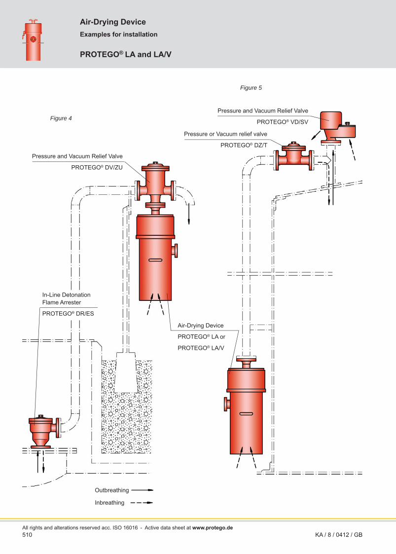
Examples for installation
Air-Drying Device
PROTEGO® LA and LA/V
All rights and alterations reserved acc. ISO 16016KA / 8 / 0412 / GB
Outbreathing
Inbreathing
Figure 5
Figure 4
In-Line Detonation Flame Arrester
PROTEGO® DR/ES
Air-Drying Device
PROTEGO® LA or
PROTEGO® LA/V
Pressure and Vacuum Relief Valve
PROTEGO® DV/ZU
Pressure and Vacuum Relief Valve
PROTEGO® VD/SV
Pressure or Vacuum relief valve
PROTEGO® DZ/T
- Active data sheet at www.protego.de

511KA / 8 / 0412 / GB
Air-drying devices of types LA or LA/V may be integrated into complete tank venting systems (see fi gures 4 and 5).
If fl ammable liquids are stored in the tank, then fl ame arresters have to be installed in addition to the air-drying device and the pressure and vacuum relief valves. Depending on the operating conditions it is also possible to combine other vent valves with the integrated air-drying device.
When the set vacuum is reached in the tank, the vacuum relief valve – for instance PROTEGO® type DZ/T or DV/ZU on fi gures 4 and 5 – connected to the air-drying device opens and the dry-ing device LA sucks in atmospheric air while the drying agent (KC® drying pearls) absorbs the atmospheric humidity.
The drying agent must be replaced and regenerated when depleted. Using a control cartridge, it is easily possible to deter-mine whether the drying agent is saturated with humidity.
If the specifi ed pressure is reached in the examples shown in fi gures 4 or 5 the pressure side of the combined pressure and vacuum relief valve opens and the product vapour/air mixture escapes into the atmosphere. The valve could be for instance PROTEGO® type VD/SV or DV/ZU. Alternatively it is possible to pass the product vapour/air mixture through a suitable valve – e.g. PROTEGO® type DV/ZU into an exhaust line or exhaust system. Under pressure the vacuum side of the above valves remains closed and the product vapours cannot pass into the drying agent.
In larger tanks it is recommended to also use combined pressure and vacuum relief valves e.g. PROTEGO® type VD/SV. This ensures that in an emergency (failure of air-drying device) atmospheric air can be sucked in directly through the vacuum side. Often direct atmospheric emergency venting is required yet it is neither possible nor necessary to size the air-drying device for the maximum volume fl ow calculated (pump fl ow-rate and thermal fl ow according to EN 14015 or API 2000). Maximum thermal fl ow occurs only rarely and it is therefore usually suffi cient to size the air-drying device according to the pump fl ow-rate for emptying and a thermal fl ow portion of approximately 25%.
Essentially, the air-drying device type PROTEGO® LA/V func-tions like type PROTEGO® LA. However, a check valve allows inbreathing only when the entire venting system – the tank and the drying container – is under vacuum at the set pressure of the check valve.
The devices are designed for venting rates suffi cient for the breathing of storage tanks. However, they do not replace any valves designed for emergency venting.
The drying agent saturation can be easily monitored using a control cartridge. The drying agent can be regenerated. Dry-ing agent and control drying pearls are not included in the PROTEGO® LA or LA/V and can optionally be ordered together with the device.
Figure 6 (page 512) shows the combination options of PROTEGO® LA/V air-drying device in complete units. The overall dimensions, fi lling volumes and fi lling weights are also given in this fi gure.
for safety and environment
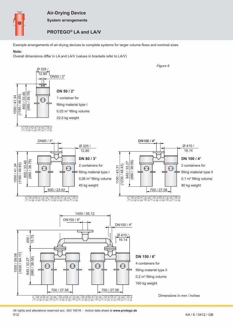
512
Air-Drying DeviceSystem arrangements
PROTEGO® LA and LA/V
All rights and alterations reserved acc. ISO 16016KA / 8 / 0412 / GB
DN50 / 2"
DN80 / 3" DN100 / 4"DN100 / 4"
DN100 / 4"DN150 / 6"
DN 50 / 2"
1 container for
fi lling material type I
0,03 m3 fi lling volume
22,5 kg weight
DN 80 / 3"
2 containers for
fi lling material type I
0,06 m3 fi lling volume
45 kg weight
DN 150 / 6"
4 containers for
fi lling material type II
0,2 m3 fi lling volume
160 kg weight
Ø 325 / 12.80
850
/ 33.
46
(985
/ 38
.78)
1050
/ 41
.34
(118
5 / 4
6.65
)
Ø 325 / 12.80
850
/ 33.
46
(985
/ 38
.78)
1050
/ 41
.34
(118
5 / 4
6.65
)
600 / 23.62
Ø 410 /16.14
Ø 410 /16.14
Example arrangements of air-drying devices to complete systems for larger volume fl ows and nominal sizes
Note: Overall dimensions differ in LA and LA/V (values in brackets refer to LA/V)
DN 100 / 4"
2 containers for
fi lling material type II
0,1 m3 fi lling volume
80 kg weight
845
/ 33.
27(9
80 /
38.5
8)
1100
/ 43
.31
(123
0 / 4
8.43
)
700 / 27.56
700 / 27.56700 / 27.56
845
/ 33.
27(9
80 /
38.5
8)
1500
/ 59
.06
(163
0 / 6
4.17
)
400
/15
.75
1400 / 55.12
Figure 6
Dimensions in mm / inches
- Active data sheet at www.protego.de

513KA / 8 / 0412 / GB
Flow Capacity Chart
Air-Drying Device
PROTEGO® LA and LA/V
LA and LA/V
pr
essu
re d
rop ∆p
LA [m
bar]
fl ow rate V. [m³/h] 1323-L
airfl ow in thousands of CFH
pr
essu
re d
rop ∆p
LA -
inch
W.C
.
for safety and environment
The fl ow capacity chart has been determined with a calibrated and TÜV certifi ed fl ow capacity test rig.Volume fl ow V
. in [m³/h] and CFH refer to the standard reference conditions of air ISO 6358 (20°C, 1bar).
Conversion to other densities and temperatures refer to Vol. 1: “Technical Fundamentals”.

514All rights and alterations reserved acc. ISO 16016
PROTEGO® NB/AP
If fast acting valve is open, drag coeffi cient amounts to 1,5
Function and Description
Fast acting bottom drain valves type NB/AP from PROTEGO®
are applied to tank seal draining nozzles to avoid leakage duringhazardous situations (pipe bursting). For this reason the devices are also called “Quick Shut off Bottom Drain Valves”. They are mainly used for low temperature liquefi ed medium (down to -196°C / -321°F) storage tanks.
The device essentially consists of the bottom plate (1), which has to be welded onto the vessel bottom, a nozzle (2), which is to be welded to the emptying line and the fl anged fast acting valve (3) with valve piston (4) and release valve cone (5) and the complete pneumatic actuating device (6), which is mounted to the roof of the vessel. Through lapped metallic valve pallet and release vent cone the required leak tightness is achieved.
The fast acting valve (3) and the actuator system (6) are con-nected by an actuator rope (7). An additional emergency rope allows the opening of the fast acting valve if the main actuator rope is damaged.
During normal operation a pneumatic cylinder holds the de-vice in the open position. The piston in the pneumatic cylinder is actuated by a control line. The piston rod is retracted with the actuation spindle to lift the valve piston and keeps the valve open during normal operation. In the emergency case a remote release through a control valve closes the bottom drain valve. To close the bottom drain valve the control valve is actuated to vent the pneumatic cylinder. The dead weight of the valve piston lets it fall down and closing the valve. The control function has to be designed in such a way that the valve closes by itself even during loss of energy (Fail-Safe-Concept).
The design of the device is independent of the nominal dia-meter. The nominal diameter DN 1 is preset by the emptying line – standard is DN 150mm / 6”.
Under normal operation the valves are working unpressurized. To re-open the valve after a quick-shut-off a pressure is consid-ered which is resulting of the liquid column above and the pres-sure in the gas head space.
Material selection is in accordance to the product and the operating temperature.
The bottom plate is welded in the tank bottom. Size and weld seam must consider the engineering requisition.
with pneumatic actuator
Fast Acting Bottom Drain Valve
KA / 8 / 0511 / GB
7
e
7
e
6
Ø a
DN 2
DN 1
Ø d
b
c
f
1
2
4
5
3
electromagnetic valve
pneumatic actuating device
outbreathing
fast acting valve
lift
- Active data sheet at www.protego.de

515
Design Types and Specifi cations
Table 1: Dimensions Dimensions in mm / inchesDN 1 DN 2 a b c d e f Hub
150 / 6" 80 / 3" 200 / 7.87 1130 / 44.49 1430 / 56.30 550 / 21.65 175 / 6.89 465 / 18.31 160 / 6.30200 / 8" 80 / 3" 200 / 7.87 1130 / 44.49 1430 / 56.30 600 / 23.62 175 / 6.89 470 / 18.50 160 / 6.30
Table 2: Material of fast action bottom drain valveBottom plate with nozzle *
* upon requestValve housing with valve cone Stainless SteelGasket *Actuator rope Stainless Steel
Table 3: Material of actuating deviceHousing Stainless SteelActuator spindle Stainless SteelGuide bushing CopperGasket PTFEProtective cap Stainless SteelPneumatic cylinder Aluminium
Table 4: Flange connection type DN 2EN 1092-1, Form B, PN 40 or upon request
Necessary Data for Specifi cation
Stored medium
Operating temperature T (°C or °F)
Operating pressure p (bar or psi)
Connection size DN 1
Tank height (m or ft)
Application Example
Selection and Design
The main process data and product properties of the stored medium as well as the temperature of the stored product determine the material for the specifi c valve. Subsequently the nominal diameter and the type of connection are checked and selected.
The valve is available in nominal diameters of DN 150 mm / 6" and DN 200 mm / 8", whereas the connection for the pneumatic actuating device has a nominal diameter of DN 80 mm / 3".
The length of the actuator rope and of the emergency rope is determined by the height of the tank. The fi nal adjustment is completed during installation. The material for the gasket is determined based on the operating conditions and/or other special requirements.
The material of the valve bottom plate needs to be compatible to the material of the tank bottom plate. If the material of the bottom plate is provided by the tank manufacturer, then close coordina-tion between manufacturing planning and installation planning is necessary.
For special requirements the valve and the actuation system (e.g. with inductive position indicator) can be supplied with a special design.
Deviations from our standard design will be sized and specifi ed with the support of our engineers for the specifi c application.
KA / 8 / 0511 / GB
for safety and environment

516All rights and alterations reserved acc. ISO 16016
PROTEGO® SI/F
Internal Safety Valve
Function and Description
The PROTEGO® internal safety valve type SI/F is a shut-off valve and protects the downstream liquid lines of storage tanks and tanks in process plants of the chemical, petrochemical and pharmaceutical industries, thus increasing both safety and avail-ability of the plants.
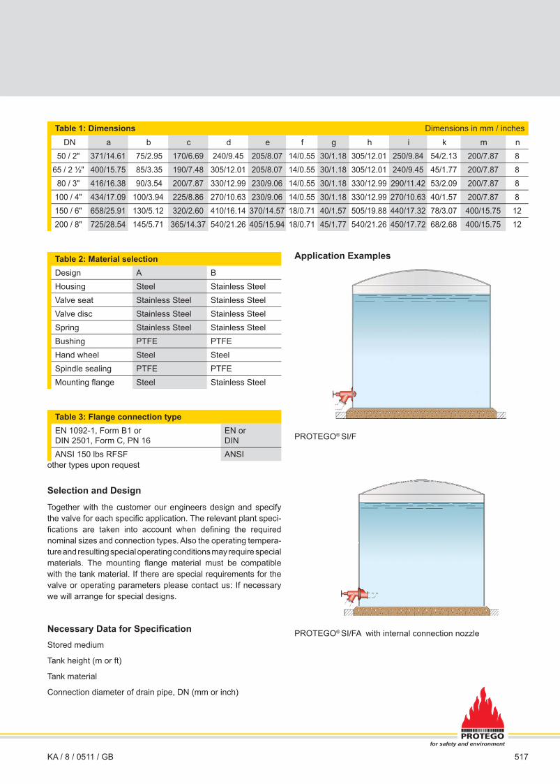
The internal safety valve SI/F (fi gure 1) consists of housing (1), mounting fl ange (2), valve seat (3), valve disc (4) and sealing (5). The mounting fl ange is welded into the tank shell. The valve seat is replaceable. The valve seat and valve disc are lapped metallic surfaces and an additional O-ring is installed to ensure the required tightness. The spindle sealing (6) can be adjusted or replaced and is designed for a test pressure of 25 bar / 363 psi.
A gate valve that is supplied by the user and serves for normal operation is connected to the external nozzle of the housing. The internal safety valve is kept open under normal operating conditions. It is only closed for longer shut-downs, in case of emergency or for necessary repairs to the gate valve.
It is closed by an “internal sealing“, e.g. the valve is closed inside of the tank. This ensures that the tank cannot leak in case of damage to external components or leakages in any connect-ed pipelines.
The special design of PROTEGO® tank shut-off valves of type SI/F is such that only the mounting fl ange (2) is welded to the tank shell, and so most other parts can be replaced. Replace-ment of important external parts does not require the draining of the tank. This fact provides signifi cant operation advantages.
Type SI/F by PROTEGO® is available in a range of nominal sizes and materials. Optionally, the internal safety valve can be equipped with an internal nozzle (7) to connect to a suction and fi lling pipe or a swing pipe system (SI/FA).
Tank shut-off valves of this type are usually operated manually. Versions with an explosion proof electric actuator for direct or remote control are also available.
Alternatively it is possible to use special versions with pneuma-tic control (PROTEGO® SI/DP) under specifi c tank design (e.g. double-shell tank).
Design Types and Specifi cations
Two designs are available:
Internal safety valve, standard design
Internal safety valve with internal connection nozzle (7)
SI/F
SI/FA
KA / 8 / 0511 / GB
c
DN
Ø f
k
DN
Ø d
Ø h
a ig
b30°
6 3 45 721
Ø m
Ø e
n =
num
ber o
f dril
l hol
es
- Active data sheet at www.protego.de
517
Table 1: Dimensions Dimensions in mm / inches
DN a b c d e f g h i k m n50 / 2" 371/14.61 75/2.95 170/6.69 240/9.45 205/8.07 14/0.55 30/1.18 305/12.01 250/9.84 54/2.13 200/7.87 8
65 / 2 ½" 400/15.75 85/3.35 190/7.48 305/12.01 205/8.07 14/0.55 30/1.18 305/12.01 240/9.45 45/1.77 200/7.87 880 / 3" 416/16.38 90/3.54 200/7.87 330/12.99 230/9.06 14/0.55 30/1.18 330/12.99 290/11.42 53/2.09 200/7.87 8
100 / 4" 434/17.09 100/3.94 225/8.86 270/10.63 230/9.06 14/0.55 30/1.18 330/12.99 270/10.63 40/1.57 200/7.87 8150 / 6" 658/25.91 130/5.12 320/2.60 410/16.14 370/14.57 18/0.71 40/1.57 505/19.88 440/17.32 78/3.07 400/15.75 12200 / 8" 725/28.54 145/5.71 365/14.37 540/21.26 405/15.94 18/0.71 45/1.77 540/21.26 450/17.72 68/2.68 400/15.75 12
Table 2: Material selectionDesign A BHousing Steel Stainless SteelValve seat Stainless Steel Stainless SteelValve disc Stainless Steel Stainless SteelSpring Stainless Steel Stainless SteelBushing PTFE PTFEHand wheel Steel SteelSpindle sealing PTFE PTFEMounting fl ange Steel Stainless Steel
Table 3: Flange connection typeEN 1092-1, Form B1 or DIN 2501, Form C, PN 16
EN or DIN
ANSI 150 lbs RFSF ANSIother types upon request
Selection and Design
Together with the customer our engineers design and specify the valve for each specifi c application. The relevant plant speci-fi cations are taken into account when defi ning the required nominal sizes and connection types. Also the operating tempera-ture and resulting special operating conditions may require special materials. The mounting fl ange material must be compatible with the tank material. If there are special requirements for the valve or operating parameters please contact us: If necessary we will arrange for special designs.
Necessary Data for Specifi cationStored medium
Tank height (m or ft)
Tank material
Connection diameter of drain pipe, DN (mm or inch)
KA / 8 / 0511 / GB
Application Examples
PROTEGO® SI/F
PROTEGO® SI/FA with internal connection nozzle
for safety and environment

518
Internal Safety Valve
PROTEGO® SI/DP
All rights and alterations reserved acc. ISO 16016KA / 8 / 0511 / GB
Function and Description
PROTEGO® SI/DP internal safety valves are used as additional shut-off valves for double-shell tanks, e.g. for storing liquefi ed gasas, cryogenic gases, other low temperature products or chemicals.
Generally a gate valve that is supplied by the user and serves for normal operation is connected to the external nozzle of the housing. The internal safety valve is kept open under normal operating conditions. It is only closed for longer shut-downs, in case of emergency or for necessary repairs to the gate valve.
The key feature of these valve devices is the actual shut-off ele-ment that is located inside the tank. The advantage of this valve design is that it prevents any leakage from the tank in the event of any external parts of the assembly getting damaged. It also means that maintenance work can be carried out on the actua-tor without any need to dismantle the pipeline or empty the tank. We recommend to use bottom drain valve PROTEGO® NB/AP for emptying the tank completely.
The internal safety valve mainly consists of three housing parts (1) with lateral connecting nozzle (2) for installation of pipeline, valve cone (3) with sealing (4) and pneumatic actuator (5). Re-quired tightness (refer to detail X) is guaranteed by grounded valve seat (10) and gasket. Bushings (8) guide the split valve spindle (6), which is equipped with double Cardan joint (7). Two compensators (9) are provided to support the length modifi ca-tion resulting from temperature variations.
Detail X
The internal safety valve is operated / opened by a simple pneu-matic actuator. The necessary force for closing the valve is gen-erated by compression springs of adequate size built into the actuator. This closing force is assisted further by the column of liquid in the tank, which presses onto the valve cone. The con-trols are designed in such a way that in the event of any fault, e.g. loss of control media (compressed air for the actuator and/or electrical power for the 3-way solenoid valve), the internal safety valve automatically closes tight.
By attaching an additional component the internal safety valve can also be operated, e.g. opened and closed, via a hand wheel. This attachment needs to be removed for the valve to operate automatically.
Type SI/DP by PROTEGO® is available in a range of nominal sizes. Optionally, the internal safety valve can be equipped with an internal nozzle to connect to a suction and fi lling pipe or a swing pipe system.
10
4
5 1 9 1 2 7 9 1 4 36 8a
L*
b
L1
DN
X
*depends on actuator
internal tank shell
external tank shell
approx. 1650
- Active data sheet at www.protego.de

519KA / 8 / 0511 / GB
Selection and Design
Together with the customer our engineers design and specify the valve for each specifi c application. The relevant plant speci-fi cations are taken into account when defi ning the required nominal sizes and connection types. Also the operating tempera-ture and resulting special operating conditions may require special materials. The mounting fl ange material must be compatible with the tank material. If there are special requirements for the valve or operating parameters please contact us: If necessary we will arrange for special designs.
Necessary Data for Specifi cationStored medium
Tank height/Tank diameter (m or ft)
Jacket space L1
Tank material
Connection diameter of drain pipe, DN (mm or inch)
Designs and Specifi cations
Table 1: Dimensions Dimensions in mm / inches
DN a b150 / 6" 300 / 11.81 350 / 13.78200 / 8" 400 / 15.75 400 / 15.75
250 / 10" 500 / 19.68 450 / 17.72300 / 12" 600 / 23.62 500 / 19.68
Table 2: MaterialselectionDesign AHousing Stainless SteelValve disc Stainless SteelValve spindle Stainless SteelSpindle sealing PTFEBushing PTFEO-rings PTFE
Table 3: Flange connection typeEN 1092-1, Form B1 or DIN 2501, Form C, PN 16; from DN 200 PN 10
EN or DIN
ANSI 150 lbs RFSF ANSI
other types upon request
Application Example
Internal safety valve PROTEGO® SI/DP for a double-shell tank.
for safety and environment

520 KA / 8 / 1212 / GBAll rights and alterations reserved acc. ISO 16016
Function and Description
PROTEGO® change-over valves type WV/T are mainly used together with other valves or safety devices (e.g. PROTEGO® fl ame arresters) on cryogenic storage tanks and on tanks in process plants of chemical, petrochemi-cal and pharmaceutical industries. They increase the operating safety of the technical equipment to be protected because each valve or safety device can be checked, main-tained or repaired without any service break-down.
The valves mainly consist of housing (1) with fl ange connections DN 1 and two lateral connection elbows (3, 4) with fl ange con-nections DN 2 and the valve disc (2). If necessary it is possible to displace and turn the connection elbows. The valve seats (9, 10) are replaceable. The valve disc with metallic sealing surface is movable on the valve spindle (6). This ensures good adjustment to the valve seats even with high temperature differences. The sealing between valve disc and valve spindle is provided by an O-ring. The valve spindle is guided by bearing bushings; to the outside it is sealed by an adjustable packing (7).
The change-over valve allows the operator to block one valve or safety device at a time by operating the hand wheel (8). In normal operation the valve disc is in central position and the gas/liquid fl ows through the two connection elbows. By turn-ing the hand wheel to the stop, one of the connection elbows (3 or 4) is blocked while the other one remains open. The actual position of the valve disc can be identifi ed from the position indi-cator (5) displayed on the valve spindle.
Due to their design and appropriately selected materials the valves are distinguished by their high functional safety and very good fl ow rates. All elements that affect the function are made out of stainless steel.
Because of the variable nozzle positions the design of the PROTEGO® change-over valves WV/T facilitates connection of valves or other safety devices both with angle or straight through connection without additional adaptors.
Positions of nozzles
drag coefficient ζ = 1,2 for valve in center position ζ = 2,6 if one side of valve closed
Change-over valves of type WV/T stand out by their simple design, easy handling, the option of quick replacement of com-ponents that effect the function and consequently by their excel-lent availability and operational reliability. The lapped metallic sealing surfaces ensure a high degree of tightness even in low temperature ranges.
These valves are not fl ame transmission proof and do not refer to the European Explosion Protection Directive 94/9/EC, even if installed in explosive atmospheres.
A hazard analysis (which considers the material selection and function of the device) shows that the device doesn’t have any potential sources of ignition.
Change-Over Valve
PROTEGO® WV/T
Ø e
b
DN1
Ø d
a
c
DN2 DN2
f3 62 7 541 89 10
I.
II.
III.
- Active data sheet at www.protego.de

521KA / 8 / 1212 / GB
Design Types and Specifi cations
Special devices in heatable design can be used under specifi c operating conditions:• with crystallizing products or products which tend to form de-
posits that affect the function• in use under extreme weather conditions in winter (frost),
when product vapour might condensate in the undercooled valve, so ice bridges could develop, which could probly block the valve disc
Selection and Design
Together with the customer our engineers design and specify the valve for the specifi c case. The relevant plant specifi cation is taken into account when defi ning the required nominal sizes and connection types. In standard versions the maximum allowable service temperature is +200°C / 392°F under a maximum allow-able operating pressure of 6 bar / 87 psi. The device must have suffi cient corrosion resistance with regard to the media to be stored or transported. If necessary, designs in special stainless steel quality should be selected.
Table 1: Dimensions Dimensions in mm / inchesDN1 80 / 3" 100 / 4" 150 / 6" 200 / 8" 200 / 8" 250 / 10"DN2 80 / 3" 100 / 4" 150 / 6" 150 / 6" 200 / 8" 250 / 10"a 780 / 30.71 780 / 30.71 960 / 37.80 960 / 37.80 1130 / 46.12 1450 / 57.09b 250 / 9.84 250 / 9.84 310 / 12.20 310 / 12.20 330 / 13.47 360 / 14.17
c * 303 / 11.93 205 / 8.07 285 / 11.22 285 / 11.22 367 / 14.98 450 / 17.72d 273 / 10.75 273 / 10.75 324 / 12.76 324 / 12.76 355 / 14.49 457 / 17.99e 250 / 9.84 250 / 9.84 250 / 9.84 250 / 9.84 400 / 16.33 400 / 15.75f 905 / 35.63 905 / 35.63 1070 / 42.13 1070 / 42.13 1195 / 48.78 1515 / 59.65
f min 810 / 31.89 810 / 31.89 950 / 37.40 950 / 37.40 1170 / 47.76 1360 / 53.54f max 995 / 39.17 995 / 39.17 1190 / 46.85 1190 / 46.85 1310 / 53.47 1695 / 66.73
* for connection fl ange DIN PN16 resp. from DN 200 DIN PN 10
Table 2: Material selectionDesign A BHousing and connection elbows Steel Stainless SteelValve disc Hastelloy HastelloyPacking PTFE PTFESpindle sealing FPM FPMHandwheel Steel Steel
The connection fl ange material must be compatible to the material of the plant component. Special models of change-over valves are available for specifi c requirements.
Table 3: Flange connection typeEN 1092-1, Form B1 or DIN 2501, Form C, PN 16; from DN 200 PN 10 EN or DIN
other types upon requestANSI 150 lbs RFSF ANSI
Necessary Data for Specifi cation
Stored medium
Service temperature (°C or °F)
Operating pressure (bar or psi)
Tank material
Tank nozzle DN1 (mm or inches)
Tank nozzle DN2 (mm or inches)
Position of nozzle I, II or III
for safety and environment

for safety and environment
www.protego.de