protocol for the measurement of nox, co, and o2 from sources
TRANSCRIPT
SOUTH COAST AIR QUALITY MANAGEMENT DISTRICT
COMPLIANCE PROTOCOL FOR THE MEASUREMENT OF NITROGEN OXIDES, CARBON MONOXIDE, AND OXYGEN
FROM SOURCES SUBJECT TO SOUTH COAST AIR QUALITY MANAGEMENT DISTRICT
RULES 1146 AND 1146.1
MARCH 10, 2009
MONITORING & SOURCE TEST ENGINEERING BRANCH
MONITORING & ANALYSIS
TABLE OF CONTENTS PAGE
- i -
TABLE OF CONTENTS ..............................................................................................................i
1.0 OVERVIEW AND APPLICABILITY ............................................................................. 1
2.0 ENVIRONMENTAL TEST CONDITIONS.................................................................... 3
2.1 AMBIENT TEMPERATURE.......................................................................................... 3 2.2 AMBIENT RELATIVE HUMIDITY .............................................................................. 3 2.3 AMBIENT BAROMETRIC PRESSURE........................................................................ 3
3.0 COMBUSTION EQUIPMENT AND PROCESS DESCRIPTION ............................... 4
3.1 COMBUSTION EQUIPMENT DESCRIPTION............................................................. 4 3.2 PROCESS DESCRIPTION ............................................................................................. 4
4.0 ANALYTICAL REQUIREMENTS AND SAMPLING PROCEDURES USING STANDARD DISTRICT METHODS .................................. 6
4.1 APPLICABILITY ............................................................................................................ 6
4.2 DISTRICT METHOD 100.1............................................................................................ 6 4.2.1 SAMPLE CONDITIONING REQUIREMENTS......................................................... 7 4.2.2 INSTRUMENTAL ANALYZER PROCEDURES ...................................................... 8 4.2.3 FIELD SAMPLING PROCEDURE ............................................................................. 9 4.2.4 DATA ACQUISITION SYSTEM (DAS)..................................................................... 9
4.3 DISTRICT METHODS 7.1 AND 10.1 ............................................................................ 9 4.3.1 FIELD SAMPLING PROCEDURES ......................................................................... 10 4.3.2 LOW CONCENTRATION CO.................................................................................. 10 4.3.3 LOW CONCENTRATION NOx................................................................................ 11
5.0 ANALYTICAL REQUIREMENTS USING PORTABLE ANALYZER METHOD . 13
5.1 START UP..................................................................................................................... 13 5.1.1 ANALYZERS............................................................................................................. 13 5.1.2 HEATED SAMPLING LINE ..................................................................................... 13 5.1.3 MOISTURE REMOVAL SYSTEM........................................................................... 13
5.2 ANALYZER CALIBRATION ...................................................................................... 13
5.3 DATA RECORDING .................................................................................................... 14
5.4 FIELD SAMPLING PROCEDURE............................................................................... 14 5.4.1 SAMPLE POINT LOCATIONS................................................................................. 14 5.4.2 TRAVERSE SAMPLING........................................................................................... 15 5.4.3 CELL TEMPERATURE MONITORING.................................................................. 15 5.4.4 INTERFERENCE VERIFICATION AND RE-ZEROING........................................ 15
TABLE OF CONTENTS PAGE
- ii -
6.0 TESTING UNDER NON-IDEAL CONDITIONS......................................................... 17
7.0 CALCULATIONS ............................................................................................................ 19
7.1 HEATING VALUE........................................................................................................ 19
7.2 F-FACTOR CALCULATION ....................................................................................... 19
7.3 EMISSION RATE OF NOX AND CO........................................................................... 20 7.3.1 CONCENTRATION CORRECTIONS......................................................................... 20 7.3.2 NOx OR CO EMISSION (Concentration at 3% O2)..................................................... 20 7.3.3 NOx OR CO EMISSION (lb/MMBtu) ......................................................................... 21
8.0 HIGH OXYGEN CONCENTRATIONS........................................................................ 22
8.1 EMISSION SAMPLING................................................................................................ 22
8.2 FLOW DETERMINATION .......................................................................................... 22 8.2.1 VELOCITY TRAVERSES......................................................................................... 22 8.2.2 STACK FLOW RATE................................................................................................ 23 8.2.3 EXHAUST GAS MOLECULAR WEIGHT DETERMINATION............................. 24 8.2.4 MOISTURE DETERMINATION .............................................................................. 24
8.3 HEAT INPUT ................................................................................................................ 24 8.3.1 HEATING VALUE .................................................................................................... 24 8.3.2 FUEL USAGE ............................................................................................................ 24
8.4 CALCULATIONS......................................................................................................... 25 8.4.1 POLLUTANT MASS EMISSIONS ........................................................................... 25 8.4.2 HEAT INPUT CALCULATION................................................................................ 25 8.4.3 NOx OR CO EMISSION CALCULATION............................................................... 25
9.0 QUALITY ASSURANCE/ QUALITY CONTROL (QA/QC)..................................... 27
9.1 PRESSURE MEASUREMENT .................................................................................... 27 9.2 TEMPERATURE MEASUREMENTS......................................................................... 27 9.3 FUEL GAS FLOW......................................................................................................... 27 9.4 NON-GASEOUS FUEL USAGE MEASUREMENTS................................................. 28 9.5 TIME.............................................................................................................................. 28
10.0 REPORT.......................................................................................................................... 29
10.1 REPORT INFORMATION ...........................................................................................29 10.2 REPORT FORMAT....................................................................................................... 30
ATTACHMENT I DISTRICT METHOD 100.1 GENERAL REQUIREMENTS AND
NO2 TO NO CONVERTER EFFICIENCY CHECK PROCEDURE
- 1 -
COMPLIANCE PROTOCOL FOR THE MEASUREMENT OF NITROGEN OXIDES, CARBON MONOXIDE, AND OXYGEN
FROM SOURCES SUBJECT TO SOUTH COAST AIR QUALITY MANAGEMENT DISTRICT
RULES 1146 AND 1146.1
1.0 OVERVIEW AND APPLICABILITY
On September 5, 2008, the South Coast Air Quality Management District (District)
amended Rules 1146 and 1146.1, which limit emissions of nitrogen oxides (NOx) and
carbon monoxide (CO) from industrial, institutional and commercial boilers, steam
generators, and process heaters. Rule 1146 applies to devices with rated input capacity
greater than, or equal to 5 million Btu per hour, while Rule 1146.1 applies to devices with
rated capacities between 2 million and 5 million Btu per hour. Compliance with these
rules are based on District standard reference methods (Method 100.1, or Methods 7.1
and 10.1), or equivalent and approved methods that allow the use of hand-held portable
monitors. This protocol has been developed to ensure standardization of test procedures
including the use of: specified test conditions, required test methods, specifications for
test equipment, data collection/reporting, and quality assurance requirements.
An independent testing laboratory, which meets the requirements of South Coast Air
Quality Management District's Rule 304, Subdivision (k), may conduct the test. The
source testing contractor must meet the non-conflict of interest requisite specified per
Rule 304(k) and provide a non-conflict of interest statement in the final report. The
laboratory shall, in conducting the test, prepare a report of findings, including all raw data
sheets/charts, and analytical data. Testing must demonstrate to the satisfaction of the
Executive Officer that the test data was obtained using the protocol described herein.
When equipment at a facility subject to District Rules 1146 or 1146.1 cannot be tested
using this protocol, the protocol may be modified following written approval of the
Executive Officer. Measurement of NOx or CO by a continuous emissions monitoring

- 2 -
system (CEMS) as specified in Rule 1146 (c)(6) meets the test protocol described herein
for the respective pollutant.
- 3 -
2.0 ENVIRONMENTAL TEST CONDITIONS
2.1 AMBIENT TEMPERATURE
The temperature shall be monitored and recorded at fifteen minute intervals during each
test.
2.2 AMBIENT RELATIVE HUMIDITY
The relative humidity shall be monitored and recorded before and after each test.
2.3 AMBIENT BAROMETRIC PRESSURE
The barometric pressure shall be monitored and recorded before and after each test.
- 4 -
3.0 COMBUSTION EQUIPMENT AND PROCESS DESCRIPTION
3.1 COMBUSTION EQUIPMENT DESCRIPTION
The type of combustion equipment (i.e., industrial boiler, steam generator, etc.), and
control equipment shall be noted. Additionally, the rated heat input capacity and fuel
type shall be recorded. Tester shall record the equipment make, model, and serial
number.
Information regarding the fuel flow meter(s) which includes the make, model, serial
number, and the most recent calibration date, shall also be recorded. The fuel meter
calibration data shall be included with the final test report.
3.2 PROCESS DESCRIPTION
A description of the process operation during sampling shall include, but not be limited
to, the following information:
a) Provide a stepwise description explaining the entire process operation (relating
only to the combustion equipment). The description shall also include a
schematic of this process;
b) Indicate whether the operation was a continuous or batch process. If it was a
batch process, state the length of each batch interval, and when (within this
interval) the test performed;
c) If the equipment modulated during sampling, indicate the extent of modulation
with respect to firing rate;
d) State whether the equipment had operated normally;
e) Report the amount of product (i.e.- steam) supplied by the equipment;
f) If the equipment is a process heater, identify the product being heated;
- 5 -
g) Include miscellaneous data, such as steam pressure, fuel pressure and temperature,
firing rate, and the percent of rated capacity at which the combustion equipment
operated during testing.
h) Provide information regarding the operating schedule of the equipment. Include
information such as whether the equipment operates "on demand", the peak
periods of operation, and the operational hours in hours per day, days per week,
and weeks per year.
i) Submit information on the pollution control equipment, including the type of
control (low NOx burners, flue gas recirculation, selective catalytic reduction,
etc.), control parameters (flue gas recirculation rate, ammonia injection rate,
temperature of inlet gas to selective catalytic reduction equipment, etc.), and
manufacturer of the control equipment.
- 6 -
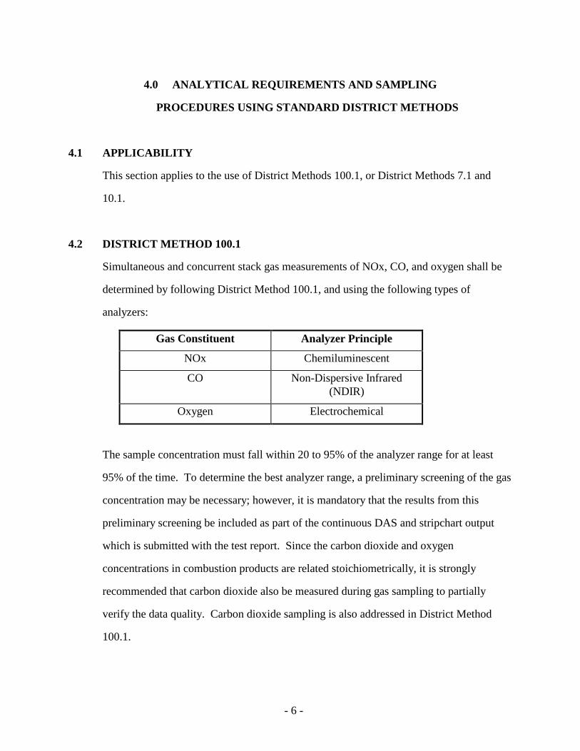
4.0 ANALYTICAL REQUIREMENTS AND SAMPLING
PROCEDURES USING STANDARD DISTRICT METHODS
4.1 APPLICABILITY
This section applies to the use of District Methods 100.1, or District Methods 7.1 and
10.1.
4.2 DISTRICT METHOD 100.1
Simultaneous and concurrent stack gas measurements of NOx, CO, and oxygen shall be
determined by following District Method 100.1, and using the following types of
analyzers:
Gas Constituent Analyzer Principle
NOx Chemiluminescent
CO Non-Dispersive Infrared (NDIR)
Oxygen Electrochemical
The sample concentration must fall within 20 to 95% of the analyzer range for at least
95% of the time. To determine the best analyzer range, a preliminary screening of the gas
concentration may be necessary; however, it is mandatory that the results from this
preliminary screening be included as part of the continuous DAS and stripchart output
which is submitted with the test report. Since the carbon dioxide and oxygen
concentrations in combustion products are related stoichiometrically, it is strongly
recommended that carbon dioxide also be measured during gas sampling to partially
verify the data quality. Carbon dioxide sampling is also addressed in District Method
100.1.
- 7 -
4.2.1 SAMPLE CONDITIONING REQUIREMENTS
For Method 100.1 testing, proper sample conditioning is essential for representative
sampling. Sample conditioning includes removal of particulate matter and moisture in
the sample gas stream without removal of the pollutants of interest. In particular, NO2,
due to its high solubility in water, is more susceptible to scrubbing than, for example, NO
or CO.
The District recommends a gas sampling system which can be used universally. The set
up includes a heated 1/4 inch stainless steel probe with 50-80 µ (micron) size sintered 316
stainless steel or ceramic filter at the tip and a short (not more than 6 feet) heated Teflon
line to a sample conditioning system. The temperature of the probe and the Teflon line
should be maintained at about 250 oF. The conditioning system consists of a pair of
standard Greenburg-Smith impingers with the stems cut to about 1 inch length from the
top, immersed in a bath containing water and dry ice pellets, and immediately followed
by a thermo-electric cooler or permeation drier. The gas temperature at the outlet of the
impinger shall be less than 60 oF, and the gas at the drier outlet shall be maintained at a
dew point less than 37 oF. If the drier cannot be directly connected to the impinger outlet
then a Teflon line heated to 10 oF above the impinger outlet gas temperature can be used
for connection. Another particulate filter (~ 5 µ) should be in line immediately after the
cooler/drier. All sample conditioning temperatures should be measured and
recorded preferably on the strip chart at least every 10 minutes. If the moisture
content of the exhaust gas is below 5% and the sample gas flow rate is less than
10 liter/minute, the impinger set-up need not be used as long as no moisture condensation
occurs in the system and the conditioned sample is maintained at the required dew point.
Precaution: Never let the water in the impingers accumulate more than 1/4 of the
impinger's height. Do not let the water bath freeze around the impingers; it may cause
cracking of glass impingers. Make sure that the thermo-electric cooler/permeation drier
- 8 -
has adequate design capacity. A good maintenance schedule should be followed for the
cooler/drier.
An example of a non-universally applicable water removal system is a refrigerated
cooling coil based system. A refrigerated cooling coil system scrubs out a high
percentage of the highly water soluble pollutants due to comparatively high residence
time and intimate contact between the sample gases and water droplets collected on the
inside wall of the coil. This type of sample conditioner is not suitable in all cases.
Other systems may be used, upon District’s approval, as long as they meet the
requirement for water removal immediately after separation from the gas stream and are
designed to minimize water contact with the gas stream.
4.2.2 INSTRUMENTAL ANALYZER PROCEDURES
A general guideline for conducting Method 100.1 is included in Attachment I. The
guideline is provided to clarify and emphasize some of the key points of Method 100.1
requirements.
Leak checks must be performed before and after each concentration sampling period.
Follow the leak check procedure as stated in Method 100.1.
Analyzer calibration error, system bias and linearity checks must be performed before and
after each concentration sampling period. A system response time test must be performed
before the concentration sampling. Tester shall survey possible interferents emitted by
the equipment, and perform interference response tests, if necessary.
NO2 to NO converter efficiency check must be performed at the beginning of each test
day. The converter efficiency check procedure is included in Attachment I.
- 9 -
4.2.3 FIELD SAMPLING PROCEDURE
Field sampling shall follow the procedures in Section 2.6 of District Method 100.1. All
QA/QC requirements of Method 100.1 shall be strictly followed. All field and laboratory
data, including calculations, annotated chart traces, and calibration results, shall be
submitted with the test report.
Record the process variables listed in Section 3.2. For combustion equipment with a
totalizing fuel meter, volumetric readings shall be recorded at the beginning and end of
the test, and once every three minutes during sampling. Combustion equipment with
non-totalizing fuel meters shall have readings recorded at the beginning and end of the
test, and once every minute during sampling.
4.2.4 DATA ACQUISITION SYSTEM (DAS)
A DAS must be used to report the analyzer readings. The DAS must provide every one-
minute and 15-minute averages in units of ppm for NOx and CO, and in percent for O2
(and CO2, if desired). The strip charts must be included in the final report as well as the
DAS output. A copy of the continuous strip chart and DAS output, beginning from the
preliminary screening (or pre-test calibrations if a screening was not conducted), and
ending following the final post-test calibrations, must be included in the final report.
4.3 DISTRICT METHODS 7.1 AND 10.1
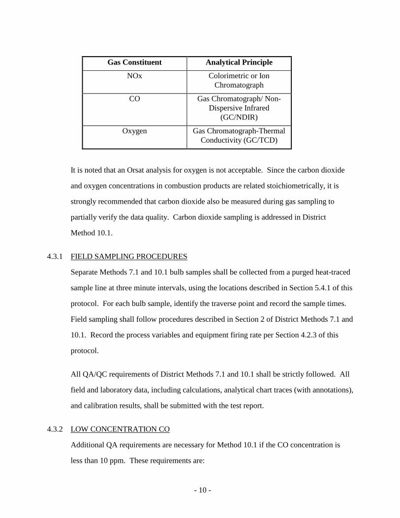
Simultaneous and concurrent stack gas bulb samples of NOx, CO, and oxygen shall be
analyzed by the following procedures:
- 10 -
Gas Constituent Analytical Principle
NOx Colorimetric or Ion Chromatograph
CO Gas Chromatograph/ Non-Dispersive Infrared
(GC/NDIR)
Oxygen Gas Chromatograph-Thermal Conductivity (GC/TCD)
It is noted that an Orsat analysis for oxygen is not acceptable. Since the carbon dioxide
and oxygen concentrations in combustion products are related stoichiometrically, it is
strongly recommended that carbon dioxide also be measured during gas sampling to
partially verify the data quality. Carbon dioxide sampling is addressed in District
Method 10.1.
4.3.1 FIELD SAMPLING PROCEDURES
Separate Methods 7.1 and 10.1 bulb samples shall be collected from a purged heat-traced
sample line at three minute intervals, using the locations described in Section 5.4.1 of this
protocol. For each bulb sample, identify the traverse point and record the sample times.
Field sampling shall follow procedures described in Section 2 of District Methods 7.1 and
10.1. Record the process variables and equipment firing rate per Section 4.2.3 of this
protocol.
All QA/QC requirements of District Methods 7.1 and 10.1 shall be strictly followed. All
field and laboratory data, including calculations, analytical chart traces (with annotations),
and calibration results, shall be submitted with the test report.
4.3.2 LOW CONCENTRATION CO
Additional QA requirements are necessary for Method 10.1 if the CO concentration is
less than 10 ppm. These requirements are:
- 11 -
1) The bulbs or canisters shall be purged with zero gas (nitrogen or hydrocarbon-free
air) before taking any samples or blanks. Analyze the purged zero gas for CO,
and reject any container that has more than 0.5 ppm CO.
2) Two field blanks of zero gas containing less than 0.5 ppm of CO in clean bulbs or
canisters shall accompany the samples to the test site. These blanks shall be
analyzed along with the field samples.
3) The CO shall be analyzed by Total Combustion Analysis using Flame Ionization
Detection (GC/FID) according to Section 5 in District Method 25.1.
4) Analyze all samples within 24 hours of sampling.
4.3.3 LOW CONCENTRATION NOx
Additional preparation and QA requirements are necessary for Method 7.1 if the NOx
concentration is less than 20 ppm. These requirements are:
1) Low NOx concentrations shall be analyzed by ion chromatography using the
Alternative Laboratory Procedure described in Section 5 of District Method 7.1.
2) Sample bulbs shall be rinsed clean with 0.1 N H2SO4 and deionized water before
sampling. Rinse, soak, and re-rinse any rubber tubing in deionized water before
sampling.
3) The absorbing solution of 0.1 N H2SO4 with 3% H2O2 shall be prepared daily
from freshly distilled or deionized water.
4) Establish and report the detection limit as nitrate for each set of analyses.
5) Adjust the calibration curve downwards to bracket all samples.
6) Do not store samples more than three days before analysis.
7) Analyze replicate samples and average the results.
- 12 -
8) Take at least one field blank sample per set to determine if contamination
occurred. Prepare a bulb with absorbing solution, and fill the bulb in the
laboratory with zero gas to ambient pressure. Take the bulb into the field during
testing, and return the bulb to the laboratory for analysis.
- 13 -
5.0 ANALYTICAL REQUIREMENTS USING PORTABLE ANALYZER METHOD
Portable analyzer sampling and analysis is an alternative to District Method 100.1 for
testing natural gas fired units, and relies on ASTM Test Method D6522. Copies of this
method is available for purchase at the following website: www.astm.org.
5.1 START UP
5.1.1 ANALYZERS
Allow analyzers to warm up according to manufacturer's instructions, and Section 10.3 of
ASTM D6522.
5.1.2 HEATED SAMPLING LINE
Energize sample pump and sample line. Allow temperatures and flows to come to
equilibrium. Since the absence of a heated sampling line may cause the NO2 results to be
under-reported, heated lines must be used to demonstrate that NOx concentrations are
below emission limits. However, the use of a heated line is optional for AQMD tests
when demonstrating that NOx concentrations exceed the required limits.
5.1.3 MOISTURE REMOVAL SYSTEM
The dew point of the conditioned gas shall not be greater than 50°F. Testing shall not be
performed if the ambient temperature falls below 55°F unless the sampling line between
the moisture removal system and the analyzer is heated above the dew point.
5.2 ANALYZER CALIBRATION
Use NIST traceable calibration gases which are certified to a minimum accuracy of + 2%.
The use of blended gases for calibrations is acceptable as long as the quality of the
calibration gas meets or exceeds EPA Protocol G1 or G2 procedures, and the calibration
gas is not used beyond its expiration date. A high span calibration gas shall be selected
- 14 -
according to ASTM D6522 procedures. Calibrate the analyzers according to ASTM
D6522 using zero gas, mid-level gas, and high-range gas. Calibrating the oxygen
analyzer using ambient air is acceptable for stack oxygen concentrations greater than
10 percent. For in-stack concentrations less than or equal to 10 percent, one of the
blended calibration gases shall be oxygen at a certified concentration between 9 percent
and 11 percent. Calibrations of each analyzer must be performed prior to and following
each sampling test day. Linearity may be checked using a gas divider if it is calibrated
according to EPA Method 205.
The analyzers shall meet the zero calibration error, span calibration error, interference
response, linearity, and stability check response specifications of ASTM D6522,
Section 9, except that linearity and stability checks may be conducted once every calendar
week. The pre- and post-test zero and span calibration error checks must be performed at
the sampling location according to Sections 10.4.1 and 10.7.1 of ASTM D6522.
5.3 DATA RECORDING
The data shall be recorded using procedures in Section 7.12 of ASTM D6522. The
recorder must allow each data point to be read at least once every minute.
5.4 FIELD SAMPLING PROCEDURE
5.4.1 SAMPLE POINT LOCATIONS
With the exception of single point sampling for exhaust stack configurations described in
Section 5.4.2(a), traverse sampling shall be performed along one cross-sectional axis of
the stack, using three points at 16.7, 50, and 83.3 percent of the stack diameter. The
sampling location upstream and downstream of flow disturbances shall be selected as
described in Section 10.1 of ASTM D6522.
- 15 -
5.4.2 TRAVERSE SAMPLING
At the start of the test, record the time and ambient conditions. Do not interrupt the flow
to the portable analyzer. Follow the Sample Collection procedures of ASTM D6522
(Section 10.6) with the following exceptions:
a) Stack diameters less than 4" ID may be sampled at a single point located at the
centroid of the stack, as long as the sampling point is located a minimum of five
stack diameters downstream, and three stack diameters upstream of a flow
disturbance. Gas concentrations shall be recorded at one minute intervals
throughout the minimum 15 minute sampling period.
b) For stacks greater than or equal to 4" ID, gas concentrations shall be recorded at
one minute intervals for five consecutive minutes at each of the three traverse
points. Note that although fifteen minutes of testing will be conducted, the actual
sampling time will be longer, depending on the response time or stability time.
Identify the traverse points being sampled along with the gas concentrations at each
point.
Determine the arithmetic mean of the gas concentrations measured during the test period.
Record the process variables and equipment firing rate per Section 3.2.
5.4.3 CELL TEMPERATURE MONITORING
Not required if sensors are temperature controlled. Sensor temperature shall not exceed
125 degrees F.
5.4.4 INTERFERENCE VERIFICATION AND RE-ZEROING
Refer to Sections 10.8 and 10.9 of ASTM D6522. In addition to the interference checks
required by ASTM D6522, an annual interference check of the NO and NO2 sensors shall
be performed when testing combustion devices which have a potential to emit SO2
concentrations greater than 10 ppm. The interference check procedure should consider
both positive and negative biases in the data, and shall demonstrate (using an equation
- 16 -
similar to that in Section 11.2 of ASTM D6522) that the combined NO and NO2
interference responses due to SO2 contribute less than 5% of the NOx concentration in the
stack. The tester shall justify the SO2 concentration selected for interference verification
using historical data, or mass balance calculations.
- 17 -
6.0 TESTING UNDER NON-IDEAL CONDITIONS
The following is a discussion of some common non-ideal conditions and their solutions
in source testing:
If there are fluctuations in the process or operating conditions, such as, changes in load,
the testing may continue as long as the operating conditions are recorded to show each
fluctuation. If the combustion equipment shuts down completely or if there are severe
fluctuations during sampling, testing must be repeated for a minimum of 15 continuous
minutes during acceptable operating conditions. The severity of fluctuations will be
determined on a case-by-case basis. If the device has the tendency to operate at a non-
ideal condition for testing, a protocol for testing at such condition should be submitted for
review and approval prior to testing.
If there are dampers or bypass stacks present, testing should be conducted as follows:
1) If excess air is frequently introduced to the exhaust stack at a variable rate,
concentration testing shall be performed while no excess air is introduced to the
exhaust stack.
2) When all or part of the exhaust gas is frequently restricted to or bypassed from the
exhaust stack, concentration testing shall be performed while the total exhaust gas
is routed to the exhaust stack (except for flue gas recirculation).
All changes in process and operating conditions and test interruptions must be
noted with the beginning and ending times of each occurrence on the field data
sheets.
For multiple stacks, perform sampling at each of the stacks during acceptable testing
conditions. Sampling at each stack need not be performed simultaneously.

- 18 -
If other non-ideal testing conditions exist, the facility must submit a source test protocol
for review and approval prior to testing.
- 19 -
7.0 CALCULATIONS
Calculations should be carried out to at least one significant digit beyond that of the
acquired data and then should be rounded off after final calculation to three significant
digits for each run. All rounding off of numbers should be in accordance with the ASTM
E380-82 procedures.
7.1 HEATING VALUE
If heating value of the fuel is measured continuously using an instrument, such as a
calorimeter, this value shall be reported in units of Btu/dscf for gaseous fuels, and Btu/gal
for liquid fuels. The density (lb/gal) shall also be reported for liquid fuels.
Note that if the heating value is determined from a fuel gas composition analysis, the
calculated heating value must be corrected to a standard temperature of 60 degrees
Fahrenheit. The following methods may be used for fuel analysis:
Gaseous Fuel ASTM D1945
Refinery Fuel ASTD D1946
Liquid Fuel ASTM D2382-88
Other ASTM methods may be used upon approval by the District. Fuel analysis must be
conducted by an independent laboratory.
7.2 F-FACTOR CALCULATION
For fuels not listed in Table 19-1 (EPA 40 CFR 60 Appendix A, Method 19), an F-Factor
may be determined using procedures described in paragraph 12.3 of Method 19. An
explanation of the analytical procedures used for determining the ultimate analysis for the
fuel shall be provided with the test report.
- 20 -
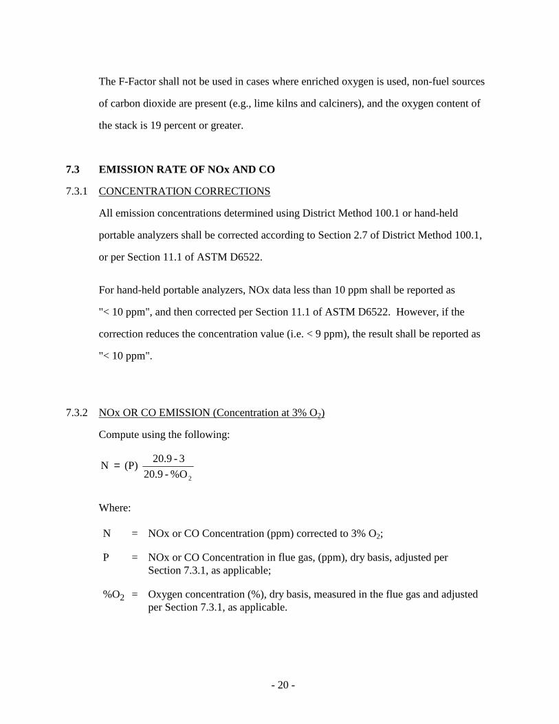
The F-Factor shall not be used in cases where enriched oxygen is used, non-fuel sources
of carbon dioxide are present (e.g., lime kilns and calciners), and the oxygen content of
the stack is 19 percent or greater.
7.3 EMISSION RATE OF NOx AND CO
7.3.1 CONCENTRATION CORRECTIONS
All emission concentrations determined using District Method 100.1 or hand-held
portable analyzers shall be corrected according to Section 2.7 of District Method 100.1,
or per Section 11.1 of ASTM D6522.
For hand-held portable analyzers, NOx data less than 10 ppm shall be reported as
"< 10 ppm", and then corrected per Section 11.1 of ASTM D6522. However, if the
correction reduces the concentration value (i.e. < 9 ppm), the result shall be reported as
"< 10 ppm".
7.3.2 NOx OR CO EMISSION (Concentration at 3% O2)
Compute using the following:
2%O - 20.9
3 - 20.9 (P) N =
Where:
N = NOx or CO Concentration (ppm) corrected to 3% O2;
P = NOx or CO Concentration in flue gas, (ppm), dry basis, adjusted per Section 7.3.1, as applicable;
%O2 = Oxygen concentration (%), dry basis, measured in the flue gas and adjusted per Section 7.3.1, as applicable.
- 21 -
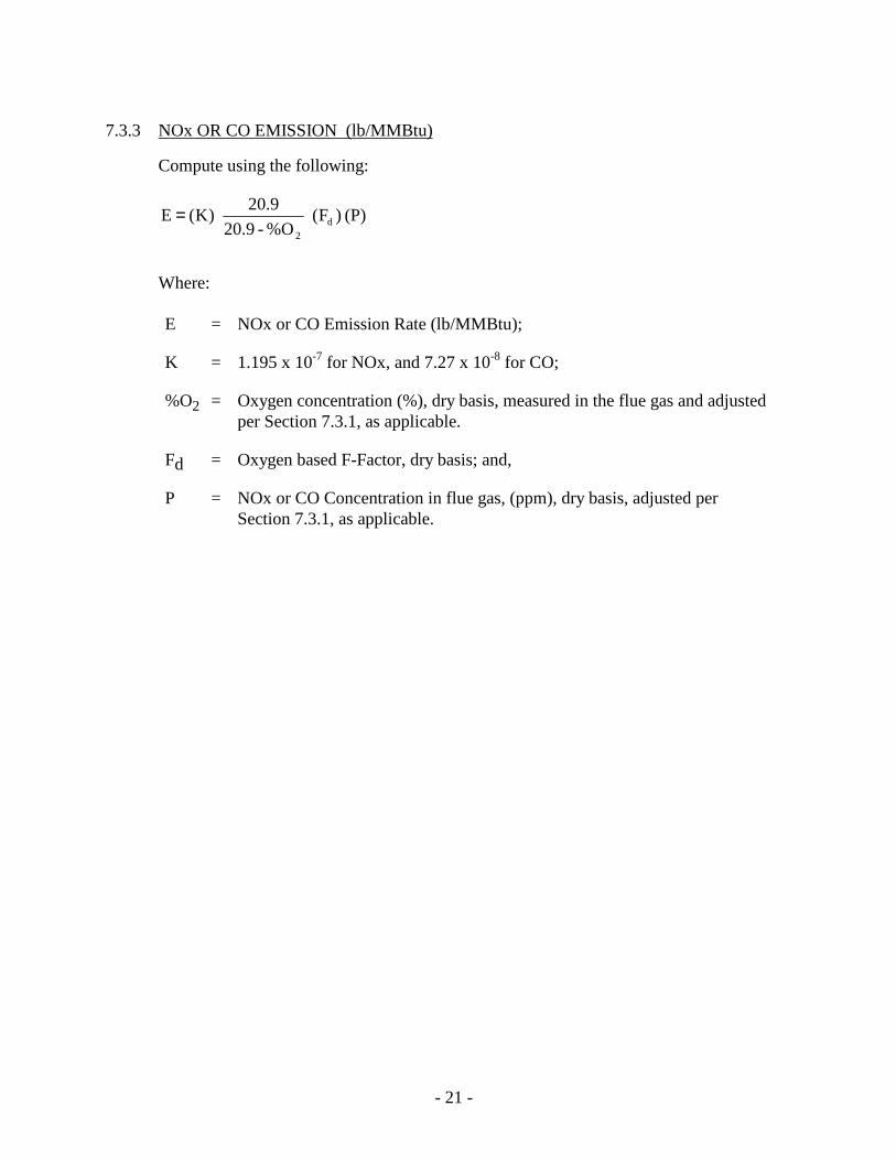
7.3.3 NOx OR CO EMISSION (lb/MMBtu)
Compute using the following:
(P) )F( %O - 20.9
20.9 )K( E d
2
=
Where:
E = NOx or CO Emission Rate (lb/MMBtu);
K = 1.195 x 10⁻⁷ for NOx, and 7.27 x 10⁻⁸ for CO;
%O2 = Oxygen concentration (%), dry basis, measured in the flue gas and adjusted per Section 7.3.1, as applicable.
Fd = Oxygen based F-Factor, dry basis; and,
P = NOx or CO Concentration in flue gas, (ppm), dry basis, adjusted per Section 7.3.1, as applicable.
- 22 -
8.0 HIGH OXYGEN CONCENTRATIONS
Because the oxygen correction term is in the denominator of the equations presented in
Section 7.3.2 and 7.3.3, errors in oxygen measurements at concentrations approaching
20.9% are greatly magnified in the calculation of NOx or CO emissions. Hence, an
alternative procedure for accurately determining NOx and CO emissions at high oxygen
concentrations is necessary. This section describes an alternative procedure for
determining Rules 1146 and 1146.1 compliance (in units of lb/MMBtu) at stack oxygen
concentrations exceeding 19%.
8.1 EMISSION SAMPLING
The procedures outlined in Section 4.2 shall be strictly followed. Sampling shall be
conducted over a continuous period of not less than 30 minutes.
8.2 FLOW DETERMINATION
8.2.1 VELOCITY TRAVERSES
The exhaust flow rate shall be determined in order to calculate the pollutant mass
emission rate. For stacks, or exhaust pipes, without existing sampling ports, determine
the best sampling port location using SCAQMD Method 1.1. In order to satisfy Method
1.1, the exhaust pipe may need to be lengthened. If so, a temporary alteration may be
made by attaching to the exhaust pipe an extension of the same size and shape as the
original pipe, where the connecting seam does not cause a flow disturbance and is leak
free.
Traverse sampling is necessary for the determination of stack gas velocity. The number
of traverse points must be determined in accordance with SCAQMD Method 1.1 for
stacks with diameters greater than 12 inches and SCAQMD Method 1.2 for stacks with
- 23 -
diameters 4 to 12 inches. All traverse points, as determined by Method 1.1 or 1.2, must
be used for measuring stack gas velocity.
If conditions such as negative flow and/or severe cyclonic flow exist that reduce the
accuracy and precision of velocity measurements, an alternative location must be chosen
where this condition does not exist.
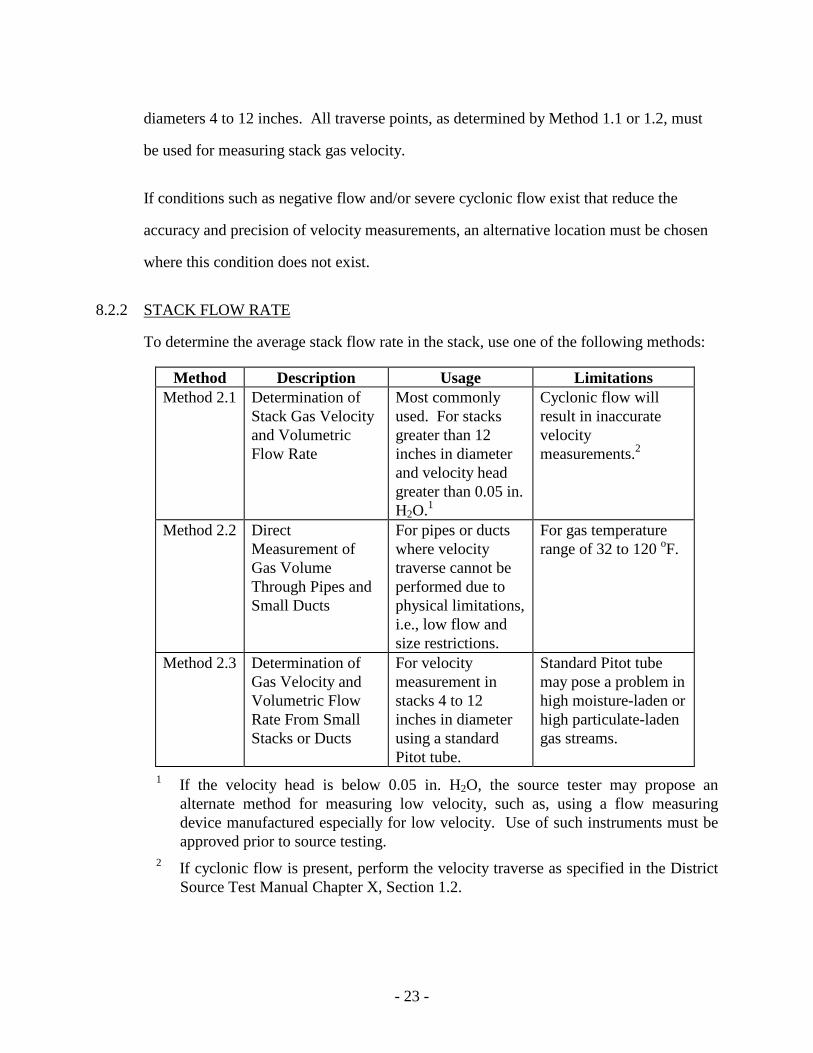
8.2.2 STACK FLOW RATE
To determine the average stack flow rate in the stack, use one of the following methods:
Method Description Usage Limitations Method 2.1 Determination of
Stack Gas Velocity and Volumetric Flow Rate
Most commonly used. For stacks greater than 12 inches in diameter and velocity head greater than 0.05 in. H2O.1
Cyclonic flow will result in inaccurate velocity measurements.2
Method 2.2 Direct Measurement of Gas Volume Through Pipes and Small Ducts
For pipes or ducts where velocity traverse cannot be performed due to physical limitations, i.e., low flow and size restrictions.
For gas temperature range of 32 to 120 oF.
Method 2.3 Determination of Gas Velocity and Volumetric Flow Rate From Small Stacks or Ducts
For velocity measurement in stacks 4 to 12 inches in diameter using a standard Pitot tube.
Standard Pitot tube may pose a problem in high moisture-laden or high particulate-laden gas streams.
1 If the velocity head is below 0.05 in. H2O, the source tester may propose an alternate method for measuring low velocity, such as, using a flow measuring device manufactured especially for low velocity. Use of such instruments must be approved prior to source testing.
2 If cyclonic flow is present, perform the velocity traverse as specified in the District Source Test Manual Chapter X, Section 1.2.
- 24 -
The velocity traverse shall be performed simultaneously with concentration testing. If
pulsating flow is detected during the velocity traverses, use a dampening method as
described in Chapter X Section 9 of the SCAQMD Source Test Manual.
8.2.3 EXHAUST GAS MOLECULAR WEIGHT DETERMINATION
Carbon dioxide (CO2) and O2 concentrations are needed to determine the molecular
weight of the exhaust gas in order to calculate the standard volumetric flow rate. These
gases shall be measured using Method 100.1. All testing procedures and QA/QC
requirements must satisfy those as stated in the method. Molecular weight sampling shall
be performed simultaneously with the NOx and CO sampling.
8.2.4 MOISTURE DETERMINATION
In conjunction with the velocity traverses, conduct moisture sampling using Method 4.1.
A single sampling point near the stack center is acceptable for moisture sampling. If low
moisture is suspected (< 5%), increase the sampling time to acquire at least twice the
required sample volume.
8.3 HEAT INPUT
8.3.1 HEATING VALUE
The higher heating value of the fuel shall be determined according to the procedures in
Section 7.1 of this protocol.
8.3.2 FUEL USAGE
The fuel usage shall be determined using a totalizing fuel meter by calculating the
difference between the facility's fuel meter volume readings (in cubic feet) prior to, and
following the Method 100.1 sampling period. This fuel usage must be corrected to
standard pressure (14.7 psia) and temperature (60°F). The time between fuel meter
readings (in minutes) must also be accurately recorded.
- 25 -
Meter calibration data must be submitted with the final report.
8.4 CALCULATIONS
8.4.1 POLLUTANT MASS EMISSIONS
The NOx and CO mass emissions rate (in units of lb/hr) shall be determined according to
the following equation:
(P) (Flow) (MW) )10 x (1.583 E -7R =
Where:
ER = NOx or CO Emission Rate (lb/hr);
MW = Molecular weight, 46 for NOx, and 28 for CO;
Flow = Exhaust stack flow rate (dscfm), determined using calculation procedures in District Method 2.1;
P = NOx or CO Concentration in flue gas, (ppm), dry basis, corrected according to Section 2.7 of District Method 100.1.
8.4.2 HEAT INPUT CALCULATION
The heat input shall be calculated from data collected in Section 8.3 as follows:
)(10 (60) (HHV) (U) HI -6=
Where:
HI = Heat input rate (MMBtu/hr);
U = Fuel input rate (scf/min), calculated by dividing the fuel usage (Section 8.3.2) by the minutes between fuel meter readings;
HHV = Higher heating value of the fuel, determined in Section 8.3.1.
8.4.3 NOx OR CO EMISSION CALCULATION
The NOx or CO emissions, for Rule 1146 or Rule 1146.1 compliance determination, is
calculated by:
- 26 -
(HI) / )(E C RR1146 =
Where:
CR1146 = NOx or CO emissions (lb/MMBtu) for Rule 1146 or Rule 1146.1 compliance determination;
ER = NOx or CO Emission Rate (lb/hr), determined from Section 8.4.1;
HI = Heat input rate (MMBtu/hr), determined from Section 8.4.2.
- 27 -
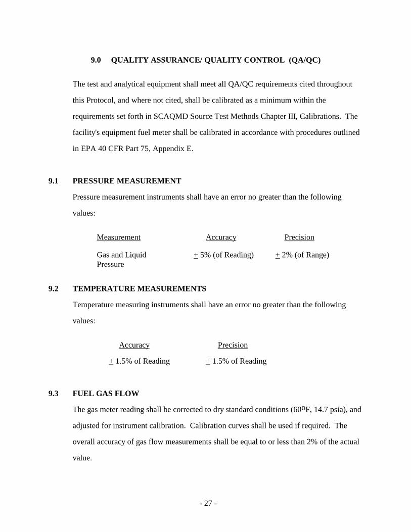
9.0 QUALITY ASSURANCE/ QUALITY CONTROL (QA/QC)
The test and analytical equipment shall meet all QA/QC requirements cited throughout
this Protocol, and where not cited, shall be calibrated as a minimum within the
requirements set forth in SCAQMD Source Test Methods Chapter III, Calibrations. The
facility's equipment fuel meter shall be calibrated in accordance with procedures outlined
in EPA 40 CFR Part 75, Appendix E.
9.1 PRESSURE MEASUREMENT
Pressure measurement instruments shall have an error no greater than the following
values:
Measurement Accuracy Precision
Gas and Liquid + 5% (of Reading) + 2% (of Range) Pressure
9.2 TEMPERATURE MEASUREMENTS
Temperature measuring instruments shall have an error no greater than the following
values:
Accuracy Precision
+ 1.5% of Reading + 1.5% of Reading
9.3 FUEL GAS FLOW
The gas meter reading shall be corrected to dry standard conditions (60oF, 14.7 psia), and
adjusted for instrument calibration. Calibration curves shall be used if required. The
overall accuracy of gas flow measurements shall be equal to or less than 2% of the actual
value.
- 28 -
9.4 NON-GASEOUS FUEL USAGE MEASUREMENTS
The accuracy of non-gaseous fuel use measurements, using calibration curves if required,
shall be equal to or less than + 2% of the actual value. Calibration data shall be submitted
with the test report.
9.5 TIME
The elapsed time measurement shall be measured with an instrument that is accurate
within + 0.5 seconds per hour.
- 29 -
10.0 REPORT
10.1 REPORT INFORMATION
The following information is to be included in the test report:
1. All printouts, must be included in the final report and must be clearly identified as to:
-location/source -range changes
-operator initials -range of measurement
-date/running times -calibrations
-actual test interval -cal gas concentration/cyl. no.
-contaminant/diluent -range of calibration
2. A summary of the Source Test results.
3. A brief process description. Indicate equipment operation during testing; as well as any
other information which may influence the final report.
4. A simple schematic diagram of the process, showing the sampling location, with respect
to the upstream and downstream flow disturbances.
5. The sampling and analytical procedures. Be specific about all aspects of sampling and
analysis. Include diagrams of test equipment and methods.
6. Complete raw field data, including production data indicative of the testing interval,
analyses, and the test results (show all calculations).
7. Calibration data regarding all sampling and measuring equipment utilized during testing
(see District Source Testing Manual, Chapter III or "Quality Assurance Handbook For
Air Pollution Measurement Systems", Vol. III, U.S. EPA-600/4-77-0276).
- 30 -
10.2 REPORT FORMAT
The report shall be submitted in a hardcopy format. For ease of processing however, it is
recommended that an electronic copy accompany the hardcopy report. In addition, each
page of the final test report (including raw analytical and field data, as well as other third
party reports) must have a unique and sequential page number which can be referenced in
correspondences. The information in the final report shall be formatted as follows:
I. Table of Contents
II. Executive Summary
III. Introduction
IV. Equipment Description Including Fuel Meter(s), if applicable. This section shall include a statement that verifies acceptability of the method test location and the operating condition during the test.
V. Test Critique
VI. List of Sampling and Analytical Methods Used. This section shall include a list of the test methods used. Do not include copies or descriptions of the source test methods if the methods were adhered to as written. If exceptions were made to the methods, submit only an explanation of the exceptions.
VII. Appendices
A. SCAQMD Method Results
B. Portable Analyzer Results
C. Schematics of Stack Sampling Locations
D. Field Data Sheets - testing method and process data sheets shall be compiled in separate sections
E. QA/QC
F. Laboratory Analytical Data
G. Calibration Data and Calculations
H. Calibration Gas Certificates
I. Chain of Custody Information (as necessary)
J. Process Operating Data Including Fuel Usage During Test
K. Calculations Using Fuel F-Factor (if necessary)
L. Certifications
ATTACHMENT I
DISTRICT METHOD 100.1 GENERAL REQUIREMENTS AND NO2 TO NO CONVERTER EFFICIENCY CHECK PROCEDURE
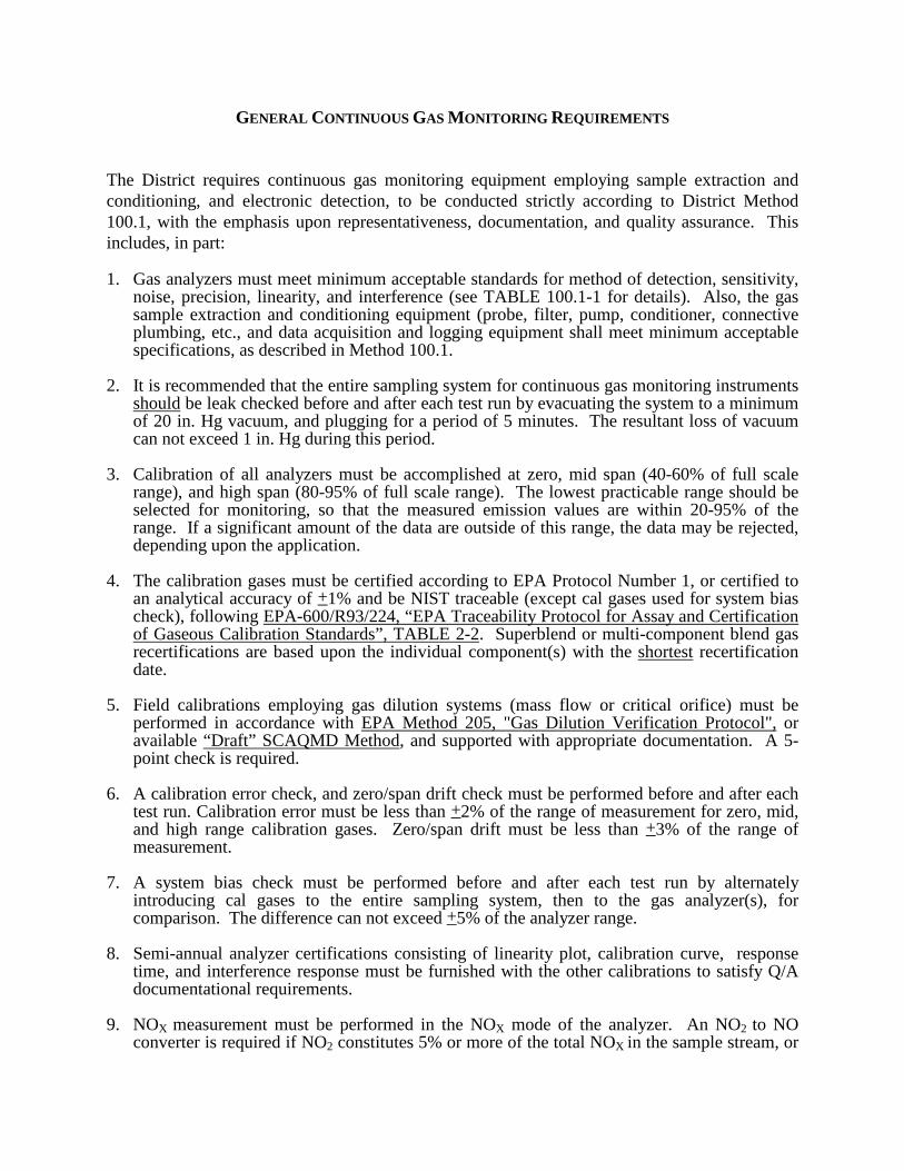
GENERAL CONTINUOUS GAS MONITORING REQUIREMENTS
The District requires continuous gas monitoring equipment employing sample extraction and conditioning, and electronic detection, to be conducted strictly according to District Method 100.1, with the emphasis upon representativeness, documentation, and quality assurance. This includes, in part:
1. Gas analyzers must meet minimum acceptable standards for method of detection, sensitivity, noise, precision, linearity, and interference (see TABLE 100.1-1 for details). Also, the gas sample extraction and conditioning equipment (probe, filter, pump, conditioner, connective plumbing, etc., and data acquisition and logging equipment shall meet minimum acceptable specifications, as described in Method 100.1.
2. It is recommended that the entire sampling system for continuous gas monitoring instruments should be leak checked before and after each test run by evacuating the system to a minimum of 20 in. Hg vacuum, and plugging for a period of 5 minutes. The resultant loss of vacuum can not exceed 1 in. Hg during this period.
3. Calibration of all analyzers must be accomplished at zero, mid span (40-60% of full scale range), and high span (80-95% of full scale range). The lowest practicable range should be selected for monitoring, so that the measured emission values are within 20-95% of the range. If a significant amount of the data are outside of this range, the data may be rejected, depending upon the application.
4. The calibration gases must be certified according to EPA Protocol Number 1, or certified to an analytical accuracy of +1% and be NIST traceable (except cal gases used for system bias check), following EPA-600/R93/224, “EPA Traceability Protocol for Assay and Certification of Gaseous Calibration Standards”, TABLE 2-2. Superblend or multi-component blend gas recertifications are based upon the individual component(s) with the shortest recertification date.
5. Field calibrations employing gas dilution systems (mass flow or critical orifice) must be performed in accordance with EPA Method 205, "Gas Dilution Verification Protocol", or available “Draft” SCAQMD Method, and supported with appropriate documentation. A 5-point check is required.
6. A calibration error check, and zero/span drift check must be performed before and after each test run. Calibration error must be less than +2% of the range of measurement for zero, mid, and high range calibration gases. Zero/span drift must be less than +3% of the range of measurement.
7. A system bias check must be performed before and after each test run by alternately introducing cal gases to the entire sampling system, then to the gas analyzer(s), for comparison. The difference can not exceed +5% of the analyzer range.
8. Semi-annual analyzer certifications consisting of linearity plot, calibration curve, response time, and interference response must be furnished with the other calibrations to satisfy Q/A documentational requirements.
9. NOX measurement must be performed in the NOX mode of the analyzer. An NO2 to NO converter is required if NO2 constitutes 5% or more of the total NOX in the sample stream, or
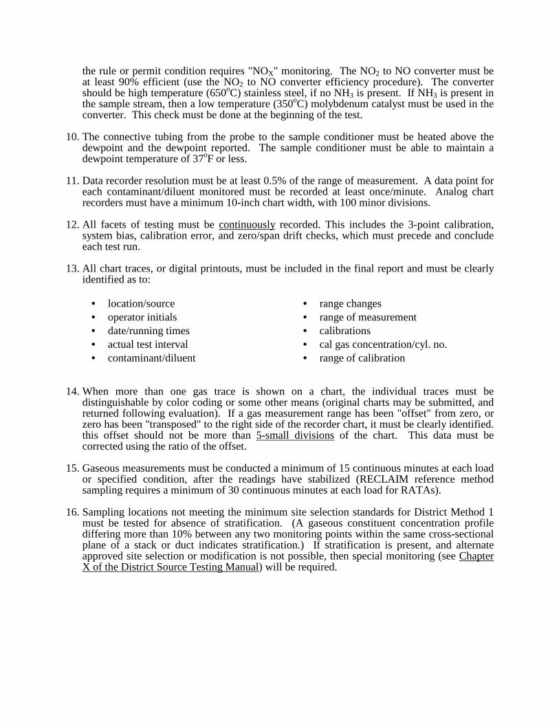
the rule or permit condition requires "NOX" monitoring. The NO2 to NO converter must be at least 90% efficient (use the NO2 to NO converter efficiency procedure). The converter should be high temperature (650oC) stainless steel, if no NH3 is present. If NH3 is present in the sample stream, then a low temperature (350oC) molybdenum catalyst must be used in the converter. This check must be done at the beginning of the test.
10. The connective tubing from the probe to the sample conditioner must be heated above the dewpoint and the dewpoint reported. The sample conditioner must be able to maintain a dewpoint temperature of 37oF or less.
11. Data recorder resolution must be at least 0.5% of the range of measurement. A data point for each contaminant/diluent monitored must be recorded at least once/minute. Analog chart recorders must have a minimum 10-inch chart width, with 100 minor divisions.
12. All facets of testing must be continuously recorded. This includes the 3-point calibration, system bias, calibration error, and zero/span drift checks, which must precede and conclude each test run.
13. All chart traces, or digital printouts, must be included in the final report and must be clearly identified as to:
• location/source • range changes • operator initials • range of measurement • date/running times • calibrations • actual test interval • cal gas concentration/cyl. no. • contaminant/diluent • range of calibration
14. When more than one gas trace is shown on a chart, the individual traces must be distinguishable by color coding or some other means (original charts may be submitted, and returned following evaluation). If a gas measurement range has been "offset" from zero, or zero has been "transposed" to the right side of the recorder chart, it must be clearly identified. this offset should not be more than 5-small divisions of the chart. This data must be corrected using the ratio of the offset.
15. Gaseous measurements must be conducted a minimum of 15 continuous minutes at each load or specified condition, after the readings have stabilized (RECLAIM reference method sampling requires a minimum of 30 continuous minutes at each load for RATAs).
16. Sampling locations not meeting the minimum site selection standards for District Method 1 must be tested for absence of stratification. (A gaseous constituent concentration profile differing more than 10% between any two monitoring points within the same cross-sectional plane of a stack or duct indicates stratification.) If stratification is present, and alternate approved site selection or modification is not possible, then special monitoring (see Chapter X of the District Source Testing Manual) will be required.
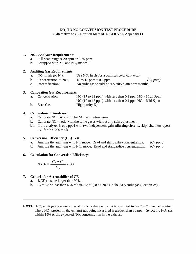
NO2 TO NO CONVERSION TEST PROCEDURE
(Alternative to O3 Titration Method-40 CFR 50.1, Appendix F) 1. NOx Analyzer Requirements
a. Full span range 0-20 ppm or 0-25 ppm b. Equipped with NO and NOx modes
2. Auditing Gas Requirements
a. NO2 in air (or N2): Use NO2 in air for a stainless steel converter. b. Concentration of NO2: 15 to 18 ppm ± 0.5 ppm (Co, ppm) c. Recertification: An audit gas should be recertified after six months.
3. Calibration Gas Requirements
a. Concentration: NO (17 to 19 ppm) with less than 0.1 ppm NO2 - High Span NO (10 to 13 ppm) with less than 0.1 ppm NO2 - Mid Span b. Zero Gas: High purity N2
4. Calibration of Analyzer:
a. Calibrate NO mode with the NO calibration gases. b. Calibrate NOx mode with the same gases without any gain adjustment. b1. If the analyzer is equipped with two independent gain adjusting circuits, skip 4.b., then repeat
4.a. for the NOx mode.
5. Conversion Efficiency (CE) Test a. Analyze the audit gas with NO mode. Read and standardize concentration. (C1, ppm) b. Analyze the audit gas with NOx mode. Read and standardize concentration. (C2, ppm)
6. Calculation for Conversion Efficiency:
100||
%0
12 xC
CCCE
−=
7. Criteria for Acceptability of CE
a. %CE must be larger than 90%. b. C1 must be less than 5 % of total NOx (NO + NO2) in the NO2 audit gas (Section 2b).
NOTE: NO2 audit gas concentration of higher value than what is specified in Section 2. may be required
where NO2 present in the exhaust gas being measured is greater than 30 ppm. Select the NO2 gas within 10% of the expected NO2 concentration in the exhaust.