prototype 5 kw steam cogenerator with linear...
TRANSCRIPT
PROTOTYPE 5 KW STEAM COGENERATOR WITH LINEAR ALTERNATOR
G. Grazzini a, A. Milazzo a*, S. Pieri b a Dipartimento di Energetica “Sergio Stecco”, via di S. Marta,3, 50130, Firenze, Italy,
b Studio SOME, Via P. Togliatti 145, 50019 Sesto Fiorentino (FI), Italy *corresponding author: [email protected]
ABSTRACT
A prototype micro-cogeneration system based on a reciprocating steam engine has been built and is now starting its experimental operation. The system has a biomass fuelled boiler, working at moderate pressure (5 bar). A condenser interfaces the steam circuit with the heat load, preferably at low temperature, such as household heating. The whole system is conceived for use in rural areas in order to reduce electricity and fossil fuel consumption.
The reciprocating engine piston is directly coupled with a linear alternator. This dramatically simplifies the engine and eliminates the side forces due to the crank mechanism. Hence, cylinder wear is reduced and operation without lubrication is allowed. Vibrations are reduced as well.
On the other hand, the system oscillation must be controlled in order to produce energy at grid frequency. This has been accomplished by an electrically operated intake valve rotating at fixed speed. An air spring has been used to balance the steam force on the piston. In this way, the reaction force can be controlled by varying the air spring volume.
This document describes the computer code that simulates the thermodynamic, mechanic and electric behaviour of the engine-alternator group. This code has been used for the design and optimization of the prototype. Furthermore, the relevant prototype features are presented.
Keywords: Steam, Reciprocating engine, Linear alternator, Biomass, Prototype.
INTRODUCTION
Since the early efforts on heat-to-work conversion through thermal power plants, it has been clear that a portion of the heat delivered to a machine by the hot source must be rejected to ambient. This evidence is formalized by the Kelvin Planck statement of the 2nd Law of Thermodynamics and may be invoked as the conceptual foundation of Combined Heat and Power (CHP) generation. Since we need heat at moderate temperature for many uses, it is
evident that fulfilling these needs with waste heat from any engine, rather than degrading high temperature heat, must be beneficial. Quantification and exploitation of this benefit is obviously more complex.
Some of the difficulty encountered by CHP proponents is due to the concentration of thermal energy conversion in big power plants, normally located quite far from potential users of waste heat. This concentration has been made possible by electric energy distribution and is beneficial, as far as energy conversion efficiency increases with power plant size. Opposite recent trend towards distributed electrical generation, aside with reduction of transmission power losses and increase of grid reliability, may give a significant contribution to the diffusion of CHP.
Another issue on the energy arena is the substitution of fossil fuels with renewable energy. Renewable energy sources are typically distributed over large areas, and hence intrinsically well suited for distributed energy conversion. If the renewable source is a combustible matter, as in the case of biomass, CHP is imperative. Carnot theorem states that the amount of waste heat from an engine is a function of the ratio between ambient temperature and hot source temperature. This ratio is high also in the case of biomass, that burns at significantly lower temperatures than fossil fuels.
In Italy, biomasses are bound to play a relevant role in the renewable energy diffusion. They are especially attractive outside urban areas, which are well served by natural gas distribution and critical in terms of pollutant emission.
Low energy density makes biomass transportation very inopportune, confirming the need to built small plants, near to the biomass producing area and tailored on the energy needs (heat and power) of the people living and working in this area. Rural areas produce significant amounts of residual biomass which, given a mean to convert them to energy, could be transformed in an opportunity. The aptitude to be stored makes biomass easier to use with respect to other renewable energies.

Once we focus on micro CHP plants installed on-site by the rural user, biomass still offers a variety of options for its utilization. A first option concerns the biomass conversion, which can include the preparation of a secondary fuel (gasification, pyrolysis, pellets, etc.) or can be a direct combustion.
The biomass-derived fuels are obviously easier to burn, but their economic cost and energy efficiency must be carefully evaluated. For a small system, directly operated by the final energy user, direct combustion seems more adequate.
The biomass, either forest or agricultural residuals, may be reduced to woodchips, in order to allow a mechanical feeding of the combustion chamber. Combustion problems, related to low and unpredictable fuel quality, must be carefully addressed, but will not be dealt with here. Minimum requirements are a primary combustion zone with high fuel-air ratio and a secondary combustion zone, with pre-heated flow of secondary air, for the completion of the oxidation. Fuel-air ratio should be controlled and particulate matter should be trapped by a suitable filter.
In some cases, the term CHP is used for “parallel” systems, i.e. work and heat production from the same heat source. Clearly, this is not a valid option under the 2nd Law of Thermodynamics point of view. In order to have a thermodynamic (and economic) benefit, work must be produced from the high temperature heat source and usable heat must be recovered from low temperature energy rejected by the engine.
All what has been said leads to specify a system comprising a combustor of woodchips, a high temperature heat exchanger producing a hot working fluid, a work producer (expander) and a low temperature heat exchanger recovering usable heat. As a first guess, we set a target for 10 kW electric power, calculating the combustor and the heat recuperator size accordingly.
DESIGN OPTIONS
Working fluid selection
The next design step is the working fluid selection, which must account for cost, environmental problems and availability in a rural area. Working fluid may be either a gas or a phase-changing substance. Recent examples of the first option, in conjunction with biomass utilization, are presented in [1] where a Stirling engine is integrated with a fluidized bed biomass combustor, or in [2] where an Ericsson engine is analyzed through energy and exergy approach. Gaseous fluids may only exchange sensible heat and hence require high flow rates in order
to manage the energy flux corresponding to the required power. Heat exchange coefficient with a gaseous fluid is limited to 300 W m
-2 K
-1 [3]
and therefore either high temperature differences or huge exchanger surfaces are required for a given power. This may explain the scarce success of gas engines, notwithstanding continuous research.
Probably the most interesting gaseous working fluid is air, as it may act as oxidant and hence allows internal combustion. In this way, both hot and cold heat exchanger are eliminated. Moreover, the working fluid is costless, safe and ubiquitously available. However, this option requires biomass conversion, which we decided to discard.
Phase changing fluids, like water, ammonia or some organic fluids, may store energy in latent form, and hence they can manage big amounts of heat with limited temperature variations. Heat transfer coefficients may reach 10000 W m
-2 K
-1
for evaporating water and 25000 W m-2
K-1
for condensing steam [3]. Recently, a lot of research has been done on Organic Rankine Cycles (ORC), which may give some thermodynamic benefit, e.g. they may have a “dry” expansion. Several fluids have been examined [4, 5], but they have lower latent heat and heat exchange coefficients than steam. Furthermore, some organic fluids are flammable, or expensive, or may damage the environment, making any fluid loss (and replacement) very troublesome. Water is safe, virtually costless (even accounting for demineralization) and thermodynamically unsurpassed, even if it requires a condenser at low pressure, which must be carefully sealed against air infiltration. Fluid refilling (e.g. in case of maintenance) may be done by the user at any time.
This second design step produces a Rankine cycle with a woodchip fired steam boiler, a steam expander, a water cooled condenser, producing usable hot water, and a condensate pump, sending back water to the boiler. Boiler pressure should be moderate, in order to reduce the cost and increase the safety of the system. In the present project a commercial boiler producing saturated steam at 5 bar gauge has been employed.
Expander
A last design step, which is extensively described in this paper, concerns the steam expander. Various kinds of expander are presented in the literature. Steam has a “wet” expansion and hence expanders that may be damaged by liquid droplets can be used only if the boiler produces highly superheated steam. This is the case of turbines, where impact of
droplets at high speed on the blades produces rapid erosion. Furthermore, remembering the power target at 10 kWel, a turbine of such a small size is hardly available on the market and likely to have a very poor efficiency. On the other hand, volumetric machines work on low speed flows (a part from intake and exhaust ports) and hence may tolerate highly humid vapour. A boiler producing saturated steam is simpler and cheaper.
Focusing on volumetric machines, it still remains to decide whether its motion should be rotary or alternating. The first option may be preferred in terms of connection to the electric generator. A rotary expander, for example, is presented in [6], but no information is given on its internal structure. A medium speed, oil-free operation is claimed. Power can range between 1 and 10 kWel. Antonelli and Martorano [7] propose to adapt a Wankel engine to steam. Scroll expanders have been proposed by Kim et al. [8].
On the other hand, Badami et al. [9, 10] concentrate on reciprocating engines. From a manufacturing point of view, reciprocating engines are normally simpler and cheaper when compared to scroll or Wankel engines. Modification of an existing engine to steam operation would undoubtedly be an easy and effective development path, at least in the prototype stage.
However, the conversion from reciprocating to rotary motion adds complication and losses. The connecting rod exerts a lateral thrust on the piston, causing increased friction and non-uniform wear on the cylinder. The crank mechanism adds volume, weight, cost and vibrations to the engine. All parts of the mechanism, from the crankshaft to the piston pin, must be lubricated. Even if all these difficulties have been successfully overcome by the internal combustion engine manufacturers along a century of evolution, a search for innovative solutions seems worth of some effort.
Free piston steam engine
Elimination of the crank-mechanism has been pursued since 1920, when the pioneer work of Pescara on free piston engines produced several prototypes and patents [11]. Early efforts focused on hot-gas producers (to be coupled with a power turbine) or pump-engine assemblies. The complication of the mechanism moving the power piston and the displacer in the “beta type” Stirling engines suggested a free-piston Stirling engine [12]. Introduction of linear alternators allowed the direct conversion of reciprocating motion in electric energy.
Even if, for now, linear alternators are available only as high technology prototypes, a biomass fuelled, free piston Stirling engine was proposed
in [13] for use in developing countries. Free piston Stirling engines are near to commercial stage, either for solar energy conversion [14] or for space applications [15] or for domestic, natural gas fuelled CHP [16].
Meanwhile, linear alternators have been proposed also for coupling with internal combustion engines, either for stationary use [17] or for hybrid vehicles [18]. Therefore, research on direct coupling between reciprocating engines and linear alternators may have a positive impact in various fields.
To the best of our knowledge, no attempt has been made to couple a steam engine (or a reciprocating engine working within an ORC) with a linear alternator.
With respect to free piston Stirling, all other engines (Ericsson, Steam, Internal Combustion, etc.) have a fundamental difference: the working fluid flows in and out of the cylinder through valves. This may be a shortcoming, being any valve a source of losses, mechanical complication, wear and sealing problems. However, in the case of a free piston engine, mechanically operated valves may be a way to control the engine frequency of operation. A fundamental feature of the proposed engine is the electrically operated intake/exhaust valve, which forces the engine to oscillate at fixed frequency. In this way, if oscillating frequency is 50 Hz, no inverter is needed for AC appliances, as far as the waveform is sufficiently close to sinusoidal.
The small size of the engine and the moderate pressure of the boiler has suggested to design a single stage engine. Furthermore, the prototype nature of this project claims for a simple and easily modifiable configuration. To this aim, a single effect system has been designed, with a steam piston and an opposing air spring that guarantees an oscillating motion. A double effect system could be envisaged in the future.
The main purpose, for now, has been the mechanical and thermodynamic project of the system. Therefore, a commercial, 5 kW linear alternator has been purchased from a U.S. manufacturer. At present this alternator is produced on request and has a quite high cost, hopefully due to decrease as the production volume increases. Its principle and operation are described in [19].
In a final configuration, the alternator should be integrated in the engine, with permanent magnets mounted on the piston and stator coils mounted on the cylinder, as was made in the Stirling CHP unit described in [16]. This will greatly simplify the system design.

Fig. 1: Linear Alternator CFIC QDRIVE 5kW.
Main engine components
The first component on the steam path is a steam flow - control valve, electrically operated through a stepper motor. This valve, coupled with a pressure transducer installed on the engine head, modulates the steam flow in order to keep the intake volume at controlled pressure.
From the intake volume, pressurized steam (maximum 5 bar) is introduced in the cylinder though a rotating valve. This valve is operated by a fixed speed electric motor, e.g. synchronous AC. The same valve controls also the discharge phase. To this aim, the cylinder head has two smaller intake and two larger exhaust ports (fig. 2). The exhaust flow is collected by the central rectangular area, while the intake arrives from the two crescent shaped areas on the sides. The disk valve, in dark grey in fig. 2, has two ports.
Exhaust ports are larger because low-pressure exhaust steam has a very large specific volume and needs a longer time to flow out of the cylinder with acceptable pressure loss.
A section of the engine and air spring assembly, without the linear alternator, is shown in figure 3.
Piston and cylinder are manufactured in anodized aluminium. The absence of side thrust allows a very strict tolerance between piston and cylinder. Hence piston rings are unnecessary. The engine simulator (which will be described later) has shown that the power loss connected to steam blow-by is acceptable. The piston-cylinder interface is not lubricated.
Fig. 2: Cylinder head with rotating valve.
Steam discharged from the exhaust ports goes to the condenser. The volume behind the piston is also connected to the condenser. In order to separate the steam zone from the air spring zone, a membrane sealing is provided. In this way, air infiltration in the steam circuit is avoided.
Figure 3: Steam engine and air spring

Fig. 4 - Complete assembly of the steam engine
and linear alternator.
The air spring has a larger diameter, downward facing piston. No sealing device, nor lubrication is present. Air blow-by is compensated by a groove that connects the air spring chamber to the ambient in the neutral position, in order to refill it whenever its pressure decreases. The air spring chamber has a movable bottom, modifying its elastic response. As will be shown later, accurate optimization of the air spring volume is the key to optimize the engine efficiency.
All steam-filled volumes are provided with condensate recovery paths.
A plunger rod exits from the bottom of the air spring and connects the engine to the alternator via an adjustable spherical coupling. A view of the engine with the linear alternator is shown in figure 4. It is quite evident that most of the system volume is occupied by the alternator.
On top of figure 4 is the steam flow – control valve. The electric motor that rotates the disk valve is not shown. Below the alternator, not shown in figure, is a position sensor that monitors the oscillation. The stroke length is quite small, 26 mm maximum.
All other system components (steam filter, condensate pump, condenser, etc.) are commercial.
The main dimensions and operating parameters of the engine are shown in table 1 and were calculated by a simulation code, including a thermodynamic, mechanic and electric model. This simulation code will be described in the next paragraph.
Table 1: Main parameters of the free piston steam engine
Operating frequency 50 Hz
Maximum stroke 26 mm
Rated power 5 kW
Maximum steam pressure 5 bar
Condenser pressure 0.2 bar
Steam piston diameter 128 mm
Air spring diameter 230 mm
Piston-cylinder clearance 0.02 mm
SIMULATION CODE
The time-marching simulation code is written in Visual Basic language. Steam properties are calculated by NIST Refprop functions, embedded in the code. The code solves a system of 12 differential equations (Table 2 at the end of the paper) by a 4th order Runge Kutta solver. Dependent variables are:
1. piston stroke;
2. piston speed;
3. steam mass in the cylinder;
4. steam internal energy
5. work delivered from start;
6. steam consumed from start;
7. pressure in the air spring chamber;
8. air mass in the spring chamber;
9. temperature in the air spring chamber;
10. pressure in the chamber above air piston;
11. mass in the chamber above air piston;
12. temperature in chamber above air piston.
Simulations are performed from still, in order to gain some information on the system start-up. If the operation is stable, a steady state operation is normally reached in about 0.4 seconds.
The cylinder volume, calculated from the piston stroke s, and the steam mass m give the steam density. Internal energy and density determine all other steam properties via Refprop functions.
Thermal power lost by the steam in the cylinder,
q& , is evaluated from steam temperature and
cylinder wall area and temperature, using a fixed heat exchange coefficient hx = 10 W m
-2 K
-1. Lost
energy by heat exchange is quite low, and hence no further analysis was dedicated to this point.
Mechanical power is evaluated as the product between steam pressure and piston speed.
During intake and exhaust phases, the steam mass flow rate and properties must be known. The code may deal with reverse flow at both intake and exhaust ports. Intake flow velocity is evaluated as a function of the pressure difference between intake volume and cylinder pressure, accounting for friction by a suitable reduction coefficient and using the sound speed as an upper limit. From the pressure and enthalpy of the intake flow, the steam density, and hence the intake mass flow, is evaluated. The total enthalpy of the intake flow will be used in the energy balance.
Exhaust phase is simulated analogously, but in this case the steam properties are those pertaining to the cylinder.
A similar procedure has been used also to evaluate steam blow-by through the piston-cylinder clearance.
The air spring simulation is quite complex, due to the presence of the pressure compensation port, that connects the chambers above and below the piston. Air temperature variations are accounted for in the energy balance.
The expressions for the derivative of the 12 dependent variables used in the Runge Kutta integration are shown in table 2.
Eq. 1 is the classic dynamic equation of a moving mass with a damping c and a spring with elastic constant k. Eq. 2 gives piston velocity v. Eq. 3 is a mass balance. Integrating the intake
flow rate inm& , eq. 4 gives the consumed steam,
which will be used to calculate the engine efficiency. Eq. 5 is the energy balance. Eq. 6 integrates the power to give the work delivered.
Air mass in the air spring (eq. 7) is calculated accounting for blow-by and refill through the compensation port. Air temperature and pressure (eq. 8 and 9) are calculated assuming an ideal gas behaviour. Analogous equations 10, 11 and 12 are written for the volume above the air spring piston.
This system of differential equations is complemented by a set of auxiliary functions that calculate the intake/exhaust port area, the air spring compensation port area and the equivalent damping that corresponds to the
linear alternator behaviour. This last parameter will be dealt with in the next paragraph.
Simulation of the linear alternator
The alternator has been factory-modified and tested for operation with 50 Hz, 220 Vac. The plunger carrying the permanent magnets is mounted on leaf springs and oscillates without friction within the laminated stator carrying the fixed windings. The manufacturer specifies a “BL product”, i.e. a constant that correlates the force on the plunger to the current flowing in the windings. Besides, a set of elliptic curves, one for each value of plunger stroke, correlates the current to the terminal voltage. These curves all share a common value of short-circuit current, while open-terminal voltages are different for each value of the plunger stroke.
All these data have been incorporated in a function that calculates the equivalent damping c multiplying the speed in equation 1.
SIMULATION RESULTS
A trial-and-error process was needed to simulate the engine, calculated unknown parameters and simulate again until convergence. For example, the global reciprocating mass is a design result that depends on the dimensioning of a set of components which, in turn, depend on the stress applied on these components by the gasses, inertia and other forces. At the end of this process, all system components have been dimensioned. The final results of the simulation are shown in this paragraph.
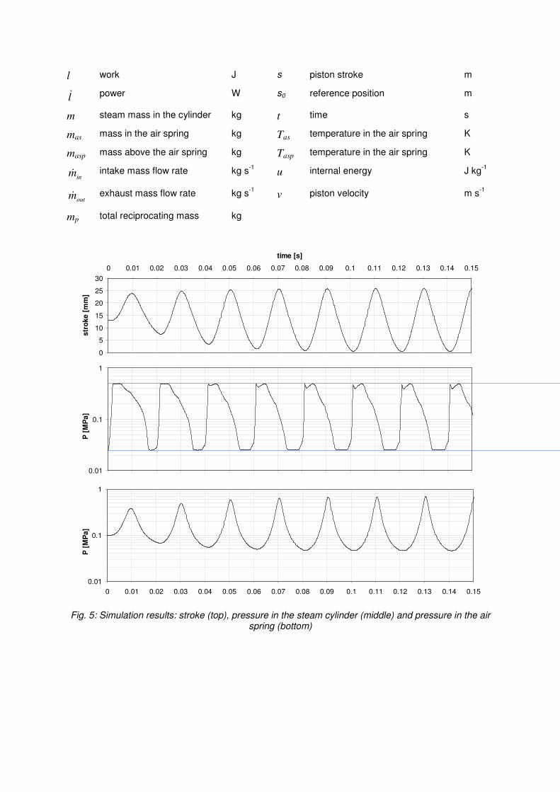
For example, fig. 5 (at the end of the paper) shows a simulation output in terms of stroke and pressures in the steam cylinder and in the air spring. Apparently the operation is stable after 0.2 ms. The time scale is set by the intake valve opening every 20 ms. Intake closes after 5.6 ms. Exhaust opens after 9.2 ms.
The red lines on the stroke diagram are the maximum allowed positions, fixed by the alternator specifications. The blue lines on the pressure diagram are the intake and exhaust pressures. The piston motion has a practically sinusoidal shape, ensuring that the produced current should not need any particular filtering. As shown in the lower diagram, as intake valve opens pressure rises sharply. Subsequent intake process is not strictly at constant pressure, due to complex interaction between piston motion and steam flow through the intake port. As intake port closes, steam expands in the cylinder until exhaust valve opens. Several tests have been made to optimize the valve timings. The result is a compromise between the effort to increase expansion work and the need to guarantee an easy path to the exhaust flow.
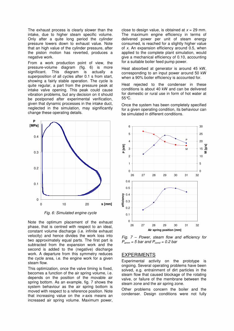
The exhaust process is clearly slower than the intake, due to higher steam specific volume. Only after a quite long period the cylinder pressure lowers down to exhaust value. Note that an high value of the cylinder pressure, after the piston motion has reverted, produces a negative work.
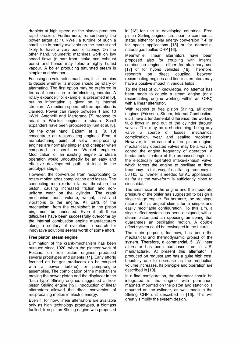
From a work production point of view, the pressure-volume diagram (fig. 6) is more significant. This diagram is actually a superposition of all cycles after 0.1 s from start, showing a fairly stable operation. The cycle is quite regular, a part from the pressure peak at intake valve opening. This peak could cause vibration problems, but any decision on it should be postponed after experimental verification, given that dynamic processes in the intake duct, neglected in the simulation, may significantly change these operating details.
0
0.1
0.2
0.3
0.4
0.5
0 10 20 30s [mm]
P
[MPa]
Fig. 6: Simulated engine cycle
Note the optimum placement of the exhaust phase, that is centred with respect to an ideal, constant volume discharge (i.e. infinite exhaust velocity) and hence divides the work loss into two approximately equal parts. The first part is subtracted from the expansion work and the second is added to the (negative) discharge work. A departure from this symmetry reduces the cycle area, i.e. the engine work for a given steam flow.
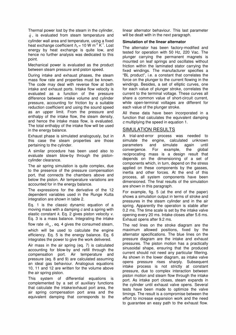
This optimization, once the valve timing is fixed, becomes a function of the air spring volume, i.e. depends on the position of the movable air spring bottom. As an example, fig. 7 shows the system behaviour as the air spring bottom is moved with respect to a reference position. Note that increasing value on the x-axis means an increased air spring volume. Maximum power,
close to design value, is obtained at x = 29 mm. The maximum engine efficiency in terms of delivered power per unit of steam energy consumed, is reached for a slightly higher value of x. An expansion efficiency around 0.5, when applied to the complete plant simulation, would give a mechanical efficiency of 0.10, accounting for a suitable boiler feed pump power.
Heat absorbed at generator is around 45 kW, corresponding to an input power around 50 kW when a 90% boiler efficiency is accounted for.
Heat rejected to the condenser in these conditions is about 40 kW and can be delivered for domestic or rural use in form of hot water at 55°C.
Once the system has been completely specified for a given operating condition, its behaviour can be simulated in different conditions.
P
M
0
1
2
3
4
5
6
26 27 28 29 30 31 32
P [
kW
]
0
5
10
15
20
25
30
M [
g/s
]
0
0.1
0.2
0.3
0.4
0.5
0.6
26 27 28 29 30 31 32
Air spring position [mm]
eff
icie
ncy
Fig. 7 – Power, steam flow and efficiency for Pamm = 5 bar and Pcond = 0.2 bar
EXPERIMENTS
Experimental activity on the prototype is ongoing. Several operating problems have been solved, e.g. entrainment of dirt particles in the steam flow that caused blockage of the rotating valve, or failure of the membrane between the steam zone and the air spring zone.
Other problems concern the boiler and the condenser. Design conditions were not fully

achieved, being the boiler pressure quite lower and the condenser pressure significantly higher.
In any case, the available experimental data have confirmed the capability of the simulation code to predict the piston stroke.
CONCLUSION
A prototype of biomass fuelled, micro-CHP plant has been designed and built. It uses a commercial steam boiler and other standard steam plant components. The steam expander is a reciprocating, free piston engine, coupled with a linear alternator, designed to operate at grid frequency. The engine-alternator assembly has been simulated by a time-resolved code accounting for all relevant phenomena. The experimental activity on the prototype has started and some initial operating problems have been solved.
ACKNOWLEDGMENT
The authors wish to thank COM s.n.c. from Vicchio (Florence) for their commitment and financial support in the realization of the prototype. This project has been funded by Regione Toscana.
REFERENCES
[1] F. Miccio, On the integration between
fluidized bed and Stirling engine for micro-
generation, Applied Thermal Engineering,
52/1 (2013), 46–53
[2] S. Bonnet, M. Alaphilippe, P. Stouffs,
Energy, exergy and cost analysis of a micro-
cogeneration system based on an Ericsson
engine, International Journal of Thermal
Sciences, 44 (2005), 1161–1168
[3] S. Kakac, H. Liu, Heat Exchangers,
Selection, Rating and Thernal Design, CRC
Press, 1998
[4] C Sprouse, C. Depcik, Review of organic
Rankine cycles for internal combustion
engine exhaust waste heat recovery, Applied
Thermal Engineering, 51 (2013), 711-722
[5] G. Qiu, Selection of working fluids for micro-
CHP systems with ORC, Renewable Energy,
48 (2012), 565-570
[6] K. Alanne, K. Saari, M. Kuosa, J. Jokisalo,
A.R. Martin, Thermo-economic analysis of a
micro-cogeneration system based on a rotary
steam engine, Applied Thermal Engineering,
44 (2012), 11-20
[7] M. Antonelli, L. Martorano, A study on the
rotary steam engine for distributed
generation in small size power plants,
Applied Energy, 97 (2012), 642–647
[8] H.J. Kim, J.M. Ahn, I. Park, P.C. Rha, Scroll
expander for power generation from a low-
grade steam source, Journal of Power and
Energy, 221 (2007), 705-712
[9] M. Badami, M. Mura, P. Campanile, F.
Anzioso, Design and performance evaluation
of an innovative small scale combined cycle
cogeneration system, Energy, 33 (2008),
1264– 1276
[10] M. Badami, M. Mura, Preliminary design and
controlling strategies of a small-scale wood
waste Rankine Cycle with a reciprocating
steam engine, Energy, 34 (2009), 1315–
1324
[11] R. Mikalsen, A.P. Roskilly, A review of free-
piston engine history and applications,
Applied Thermal Engineering, 27 (2007),
2339–2352
[12] W. Beale, Free Piston Stirling Engines -
Some Model Tests and Simulations, SAE
Technical Paper 690230 (1969)
[13] N.W. Lane, W.T. Beale, BioWatt, a biomass-
fired 1 kWe Stirling engine generator and its
applications in South Africa, 9th International
Stirling Engine Conference, South Africa,
1999
[14] Y. Bravo , M. Carvalho, L.M. Serra , C.
Monné , S. Alonso , F. Moreno , M. Muñoz,
Environmental evaluation of dish-Stirling
technology for power generation, Solar
Energy, 86, 9 (2012), 2811–2825
[15] S.Y. Kim, D.M. Berchowitz, Specific Power
Estimations for Free-Piston Stirling Engines,
4th International Energy Conversion
Engineering Conference and Exhibit
(IECEC), 2006
[16] K. Sommer, Micro-Combined Heat and
Power Appliances for one or two-family
houses for more energy efficiency, REHVA
Journal, 2001
[17] P. Famouri, W.R. Cawthorne, N. Clark, S.
Nandkumar, C. Atkinson, R. Atkinson, T.
McDaniel, S. Petreanu, Design and Testing
of a Novel Linear Alternator and Engine
System for Remote Electrical Power
Generation, IEEE paper 0-7803-4403-0,
1998
[18] C.M. Atkinson, S. Petreanu, N.N. Clark, R.J.
Atkinson, T.I. McDaniel, S.Nandkumar, P.
Famouri, Numerical Simulation of a Two-
Stroke Linear Engine-Alternator
Combination, SAE Paper 1999-01-0921
[19] G.A. Yarr, J.A. Corey, Linear electrodynamic
machine, U.S. Patent 5389844, 1995
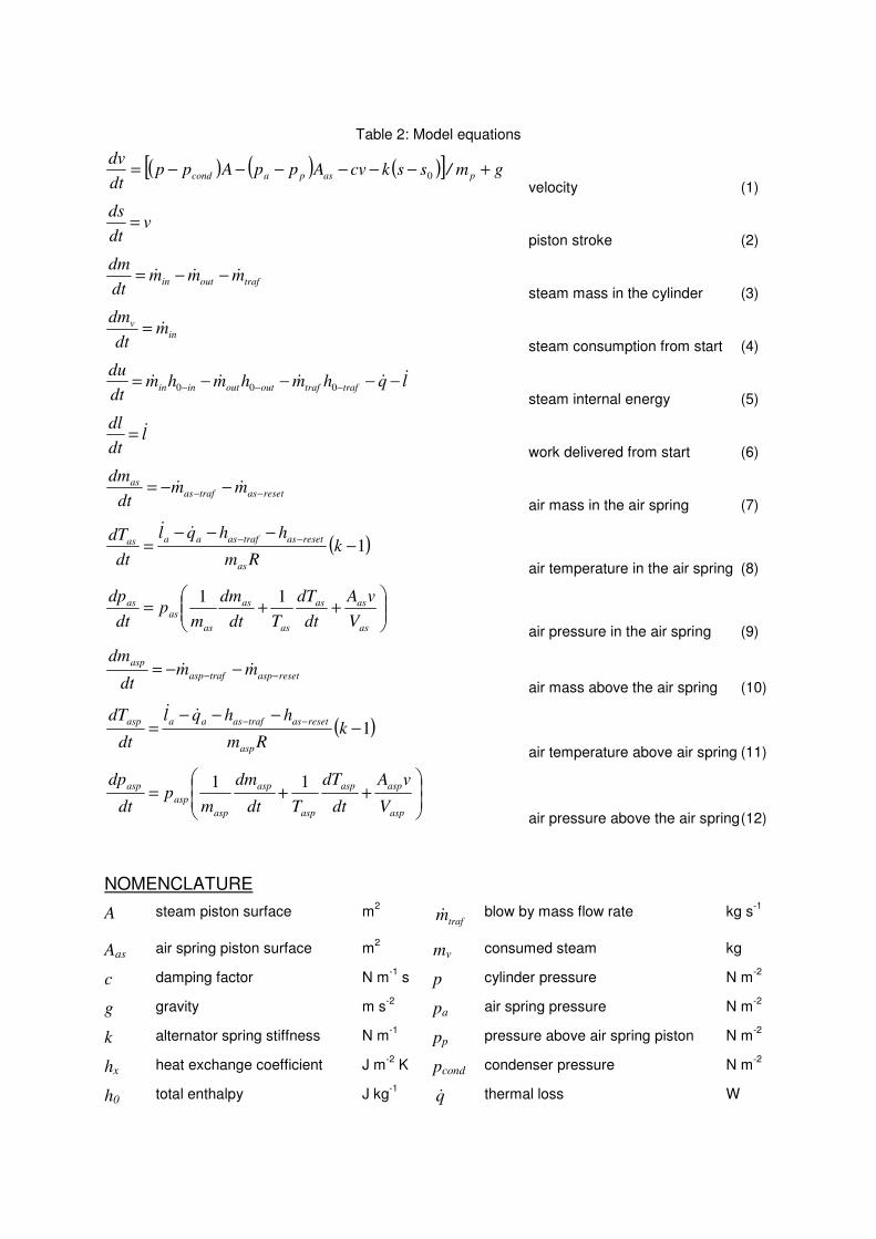
Table 2: Model equations
( ) ( ) ( )[ ] gm/sskcvAppAppdt
dvpaspacond +−−−−−−=
0
velocity (1)
vdt
ds=
piston stroke (2)
trafoutin mmmdt
dm&&& −−=
steam mass in the cylinder (3)
inv m
dt
dm&=
steam consumption from start (4)
lqhmhmhmdt
dutraftrafoutoutinin
&&&&& −−−−= −−− 000
steam internal energy (5)
ldt
dl &= work delivered from start (6)
resetastrafasas mm
dt
dm−− −−= &&
air mass in the air spring (7)
( )1−−−−
=−−
kRm
hhql
dt
dT
as
resetastrafasaaas&&
air temperature in the air spring (8)
++=
as
asas
as
as
as
asas
V
vA
dt
dT
Tdt
dm
mp
dt
dp 11
air pressure in the air spring (9)
resetasptrafasp
aspmm
dt
dm−−
−−= &&
air mass above the air spring (10)
( )1−−−−
=−−
kRm
hhql
dt
dT
asp
resetastrafasaaasp&&
air temperature above air spring (11)
++=
asp
aspasp
asp
asp
asp
asp
asp
V
vA
dt
dT
Tdt
dm
mp
dt
dp 11
air pressure above the air spring (12)
NOMENCLATURE
A steam piston surface m2
trafm&
blow by mass flow rate kg s-1
Aas air spring piston surface m2 mv consumed steam kg
c damping factor N m-1
s p cylinder pressure N m-2
g gravity m s-2
pa air spring pressure N m-2
k alternator spring stiffness N m-1
pp pressure above air spring piston N m-2
hx heat exchange coefficient J m-2
K pcond condenser pressure N m-2
h0 total enthalpy J kg-1
q&
thermal loss W
l work J s piston stroke m
l& power W s0 reference position m
m steam mass in the cylinder kg t time s
mas mass in the air spring kg Tas temperature in the air spring K
masp mass above the air spring kg Tasp temperature in the air spring K
inm&
intake mass flow rate kg s-1
u internal energy J kg-1
outm&
exhaust mass flow rate kg s-1
v piston velocity m s-1
mp total reciprocating mass kg
0
5
10
15
20
25
30
0 0.01 0.02 0.03 0.04 0.05 0.06 0.07 0.08 0.09 0.1 0.11 0.12 0.13 0.14 0.15
time [s]
str
oke [
mm
]
0.01
0.1
1
P [
MP
a]
0.01
0.1
1
0 0.01 0.02 0.03 0.04 0.05 0.06 0.07 0.08 0.09 0.1 0.11 0.12 0.13 0.14 0.15
P [
MP
a]
Fig. 5: Simulation results: stroke (top), pressure in the steam cylinder (middle) and pressure in the air spring (bottom)