prototyping of distributed embedded systems using …ceur-ws.org/vol-507/paper06.pdf · prototyping...
TRANSCRIPT

Prototyping of Distributed Embedded Systems
Using AADL⋆
Mohamed Yassin Chkouri and Marius Bozga
{Yassin.Chkouri, Marius.Bozga}@imag.fr
Verimag, Centre Equation - 2, avenue de Vignate 38610 GIERES
Abstract. Prototyping distributed applications can be extremely usefulin evaluating a design, and also in understanding the effect of differentparameters on the performance of an application. Architecture Analysisand Design Language provide adequate syntax and semantics to expressand support distributed embedded systems. This paper studies a gen-eral methodology and an associated tool for building and translatingAADL systems into a distributed application using network communica-tion protocol. This allows runtime analysis to fully asses system viability,to refine and to correct the behavior of the system using BIP. Using ourprototype we analyse the case study MPC in a native platform (PC).
1 Introduction
Distributed applications are used in many safety-critical domains such as space
and avionics. Designing distributed systems demands more attention and rigour
methodology. The produced systems have to conform to many stringent func-
tional and non-functional requirements from multiple contexts.
Ensuring all the requirements and features becomes very hard if the whole
system is hand-coded. Thus, the application code should preferably be gener-
ated automatically from a verifiable and analyzable model. This makes easier
the work of the developer and helps during the stage of code verification. Be-
sides, constructing a verifiable model from the application model using model
transformation is simpler and safer than constructing this model from source
code.
Architecture Description Languages (ADLs) have been proposed to support
the development process of embedded real-time and distributed applications.
This paper presents a definition framework for ADLs. The utility of the definition
is demonstrated by using it to differentiate and compare several existing ADLs.
This will allow us to choose an ADL according to our requirements.
Among the ADLs, AADL [3] is the Architecture Analysis and Design Lan-
guage that allows the modeling of distributed, real-time applications. AADL was
first introduced to model the hardware and software architectures in the avion-
ics domain. An AADL system model consists of components, their interfaces,
the connections between them and properties on various entities of the system
⋆ This work is partially supported by ITEA/Spices and OpenEMBeDD projects
MoDELS'09 ACES-MB Workshop Proceedings
Denver, CO, USA, October 6, 2009 65

model. The AADL standard defines a textual as well as graphical form of the
language.
AADL has been designed to build distributed real-time and embedded sys-
tems. AADL can be seen as a collection of many requirements covering many
domains. System designers and developers need to describe both functional and
non-functional requirements. These requirements must then be sorted and en-
forced at the deployment level. We will presents the set of requirements that
must be respected to build distributed systems.
We have shown in [13], how AADL systems can be automatically translated
into BIP [8] (Behavior Interaction Priority), and analyzed using the BIP toolset.
BIP is a language for the description and composition of components as well as
associated tools for analyzing models and generating code on a dedicated middle-
ware. The language provides a powerful mechanism for structuring interactions
involving rendezvous and broadcast.
In this paper, we present an extension of our translation to prototype dis-
tributed applications using BIP and network communication protocol. We begin
with a model built by the application designer, who maps its application entities
onto a hardware architecture. Then, we use AADL into BIP tool to generate
BIP model conforming to AADL semantics. Finally, we use a code generator to
generate an executable model for each systems with communication protocol.
This translation allows simulation of distributed systems specified in AADL in
addition to the application of formal verification techniques developed for BIP,
e.g. deadlock detection, verification of properties, etc.
The translation from distributed AADL systems into BIP is illustrated on
a case study: the Multi-Platform Cooperation (MPC) example provided by J.
Hugues [18]. Using our tool, we were able to run the case study in a native
platform (PC). In order, to debug and evaluate the case study before deploying
it on a distributed embedded platform.
Distributed embedded application code generation from models is not lim-
ited to AADL. In fact, distributed and high-integrity systems are probably the
domain which has the most maturity. OCARINA [17] allows model manipula-
tion, generation of formal models to perform scheduling analysis and generate
distributed applications. OCARINA allows code generation from AADL descrip-
tions to Ada. PolyORB [27] is a middleware toolset that provides distribution
services through standard programming interfaces and communication proto-
cols. However, the generated code from AADL does not take into account the
annex behavior specifications [1].
This paper is organized as follows. Section 2 gives definition and comparaison
between existing ADLs. Section 3 gives an overview of AADL. In section 4,
we explain how to translate AADL systems into distributed application using
network communication protocol. In section 5, we present a MPC case study
and it deploylment into a distributed application. Conclusions close the article
in Section 6.
MoDELS'09 ACES-MB Workshop Proceedings
Denver, CO, USA, October 6, 2009 66

2 Architecture Description Languages
Architecture Description Languages (ADLs) have been proposed as modeling
notations to support architecture-based development. An ADL is a language
that provides features for modeling a software system’s conceptual architecture,
distinguished from the system’s implementation. ADLs provide both a concrete
syntax and a conceptual framework for characterizing architectures.
The building blocks of an architectural description are (1) components, (2)
connectors, and (3) architectural configurations. Here we give a short description
of these blocks:
– A component in an architecture is a unit of computation or a data store.
– Connectors are architectural links used to model interactions among compo-
nents and rules that govern those interactions.
– Architectural configurations, or topologies, are connected graphs of compo-
nents and connectors that describe architectural structure. This information
is needed to determine whether appropriate components are connected, their
interfaces match, connectors enable proper communication, and their com-
bined semantics result in desired behavior.
A number of ADLs have been proposed for modeling architectures both within
a particular domain and as general-purpose architecture modeling languages.
We specifically consider those languages most commonly referred to as ADLs:
C2 [21, 20], Rapide [15], Darwin [19], UniCon [24], SADL [22, 26], AADL [3].
Several researchers have attempted to shed light on these issues, either by
surveying what they consider existing ADLs [28, 14] or by classifing and com-
paring several existing ADLs in some specific areas [25].
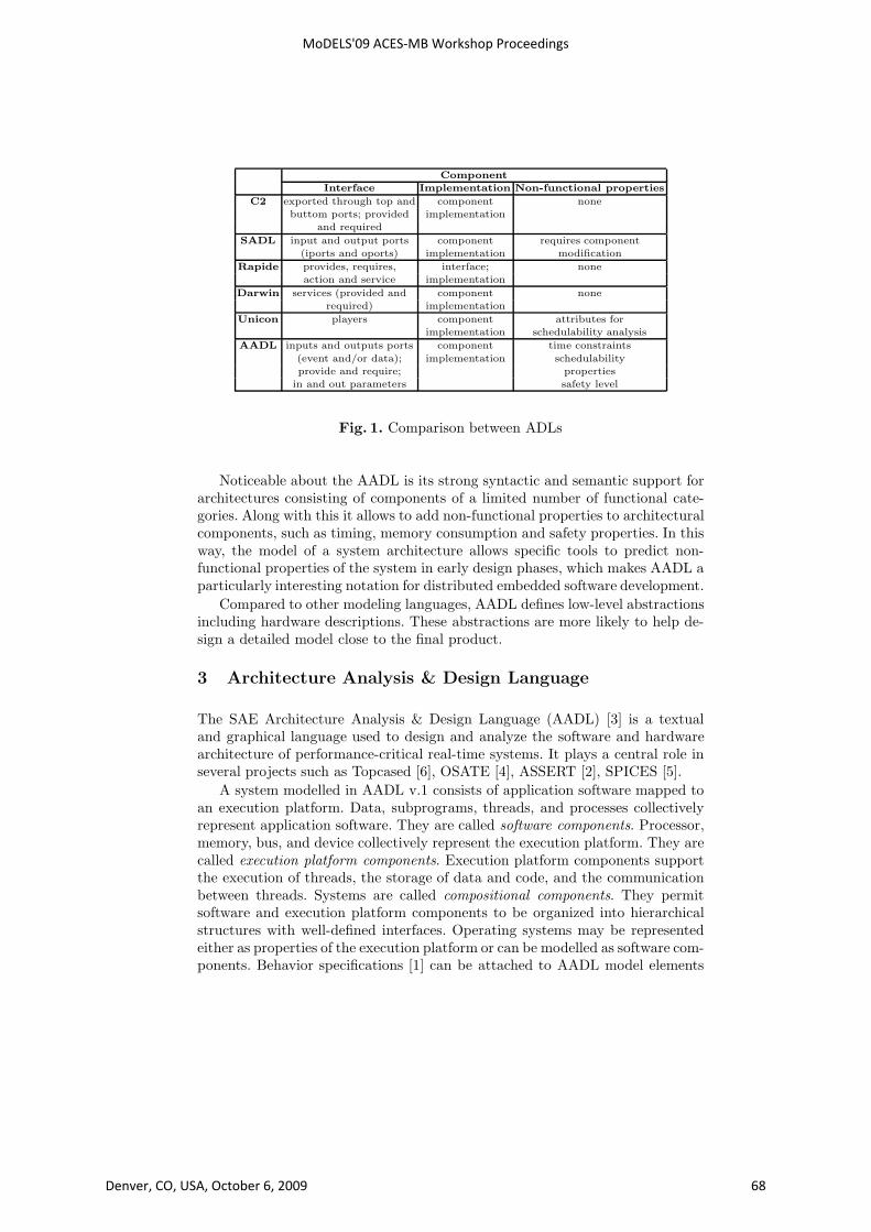
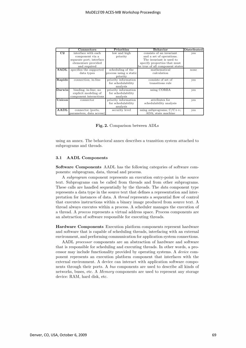
Comparisons between the languages (Figures 1, and 2) are given with respect
to: components, connections, priorities between components, behavior descrip-
tion and support for distributed embedded system.
All the above languages make distinction between a component interface
and an instance of a component that exhibits that interface. All the languages
provide syntax and semantics for component interface specification. All the lan-
guages view a component interface specification as defining a component type,
where there can be multiple instances of components that exhibit that same
interface. All languages allow a hierarchical composition that allows architec-
tures to describe software systems at different levels, by using a collection of
subcomponents and connections between those subcomponents.
C2, Darwin, SADL, and UniCon share much of their vocabulary and refer
to them simply as components; in Rapide they are interfaces; and in AADL
component categories.
In this paper, we are interested by ADL which support distributed embedded
systems, priority for schedulability analysis, behavior using state machine, and
functional and non-functional properties. AADL was first introduced to model
the hardware and software architectures in the avionics and automotives domain,
and it is backed by several industries.
MoDELS'09 ACES-MB Workshop Proceedings
Denver, CO, USA, October 6, 2009 67
Component
Interface Implementation Non-functional properties
C2 exported through top and component none
buttom ports; provided implementation
and required
SADL input and output ports component requires component
(iports and oports) implementation modification
Rapide provides, requires, interface; none
action and service implementation
Darwin services (provided and component none
required) implementation
Unicon players component attributes for
implementation schedulability analysis
AADL inputs and outputs ports component time constraints
(event and/or data); implementation schedulability
provide and require; properties
in and out parameters safety level
Fig. 1. Comparison between ADLs
Noticeable about the AADL is its strong syntactic and semantic support for
architectures consisting of components of a limited number of functional cate-
gories. Along with this it allows to add non-functional properties to architectural
components, such as timing, memory consumption and safety properties. In this
way, the model of a system architecture allows specific tools to predict non-
functional properties of the system in early design phases, which makes AADL a
particularly interesting notation for distributed embedded software development.
Compared to other modeling languages, AADL defines low-level abstractions
including hardware descriptions. These abstractions are more likely to help de-
sign a detailed model close to the final product.
3 Architecture Analysis & Design Language
The SAE Architecture Analysis & Design Language (AADL) [3] is a textual
and graphical language used to design and analyze the software and hardware
architecture of performance-critical real-time systems. It plays a central role in
several projects such as Topcased [6], OSATE [4], ASSERT [2], SPICES [5].
A system modelled in AADL v.1 consists of application software mapped to
an execution platform. Data, subprograms, threads, and processes collectively
represent application software. They are called software components. Processor,
memory, bus, and device collectively represent the execution platform. They are
called execution platform components. Execution platform components support
the execution of threads, the storage of data and code, and the communication
between threads. Systems are called compositional components. They permit
software and execution platform components to be organized into hierarchical
structures with well-defined interfaces. Operating systems may be represented
either as properties of the execution platform or can be modelled as software com-
ponents. Behavior specifications [1] can be attached to AADL model elements
MoDELS'09 ACES-MB Workshop Proceedings
Denver, CO, USA, October 6, 2009 68
Connectors Priorities Behavior Distributed
C2 interface with each low and high consists of an invariant yes
component via a priority and a set of operations.
separate port; interface The invariant is used to
elementare provided specify properties that must
and required be true of all component states
SADL specifies the supported scheduling of the mathematical none
data types process using a static calculation
priority
Rapide connection; in-line priority information consists of set of yes
for schedulability transitions rule
analysis
Darwin binding; in-line; no priority information using CORBA yes
explicit modeling of for schedulability
component interactions analysis
Unicon connector priority information attributes for yes
for schedulability schedulability analysis
analysis
AADL connector (ports, security level using subprograms; C/C++; yes
parameters, data access) ADA; state machine
Fig. 2. Comparison between ADLs
using an annex. The behavioral annex describes a transition system attached to
subprograms and threads.
3.1 AADL Components
Software Components AADL has the following categories of software com-
ponents: subprogram, data, thread and process.
A subprogram component represents an execution entry-point in the source
text. Subprograms can be called from threads and from other subprograms.
These calls are handled sequentially by the threads. The data component type
represents a data type in the source text that defines a representation and inter-
pretation for instances of data. A thread represents a sequential flow of control
that executes instructions within a binary image produced from source text. A
thread always executes within a process. A scheduler manages the execution of
a thread. A process represents a virtual address space. Process components are
an abstraction of software responsible for executing threads.
Hardware Components Execution platform components represent hardware
and software that is capable of scheduling threads, interfacing with an external
environment, and performing communication for application system connections.
AADL processor components are an abstraction of hardware and software
that is responsible for scheduling and executing threads. In other words, a pro-
cessor may include functionality provided by operating systems. A device com-
ponent represents an execution platform component that interfaces with the
external environment. A device can interact with application software compo-
nents through their ports. A bus components are used to describe all kinds of
networks, buses, etc. A Memory components are used to represent any storage
device: RAM, hard disk, etc.
MoDELS'09 ACES-MB Workshop Proceedings
Denver, CO, USA, October 6, 2009 69

Systems A system is the top-level component of the AADL hierarchy of com-
ponents. A system component represents a composite component as an assembly
of software and execution platform components. All subcomponents of a system
are considered to be contained in that system.
3.2 Connections
A connection is a linkage that represents communication of data and control
between components. This can be the transmission of control and data between
ports of different threads or between threads and processor or device components.
4 From AADL to Distributed Implementation Using BIP
4.1 The BIP Component Framework
BIP (Behavior Interaction Priority) is a framework for modeling heterogeneous
real-time components [8]. The BIP framework consists of a language and a toolset
including a frontend for editing and parsing BIP programs and a dedicated plat-
form for model validation. The platform consists of an Engine and software
infrastructure for executing models. It allows state space exploration and pro-
vides access to model-checking tools of the IF toolset [12] such as Aldebaran [11],
as well as the D-Finder tool [10]. This permits to validate BIP models and en-
sure that they meet properties such as deadlock-freedom, state invariants and
schedulability. The BIP language allows hierarchical construction [16] of com-
posite components from atomic ones by using connectors and priorities. Several
case studies were carried out such as an MPEG4 encoder [23], TinyOS [9], and
DALA [7].
4.2 Transformation from AADL to BIP
The AADL models are transformed into BIP automatically by using our AADL
to BIP translation tool described in [13]. The supported development process is
shown in the Figure 3.
The model construction methodology applied to AADL models, opens the
way for enhanced analysis and early error detection by using BIP verifications
techniques. Once the model has been generated, three model checking techniques
for verification can be applied:
D-Finder: is an interactive tool for checking deadlock-freedom for component-
based systems by using a static analysis method. It takes as input BIP programs
and applies proof strategies to eliminate potential deadlocks by computing in-
creasingly stronger deadlocks.
Model checking by Aldebaran: The second technique of verification is model-
checking by using the tool Aldebaran [11]. Exhaustive exploration by the BIP
exploration engine generates a Labeled Transition System (LTS) which can be
analyzed by model checking. e.g, Aldebaran takes as input the LTS generated
from BIP and checks for deadlock-freedom and other temporal properties.
MoDELS'09 ACES-MB Workshop Proceedings
Denver, CO, USA, October 6, 2009 70

Fig. 3. Verification cycle
Model checking with observers: The third technique of verification is by using
BIP observers to express and check requirements. Observers allow us to express
in a much simple manner most safety requirements. We apply this technique
to verify some properties as verification of communication, and verification of
thread deadline.
Simulation & Debugging: In addition to the verifications, we can simulate or
tests prototype implementations by creating an executable system. We can use
an interactive simulation and debugger to verify each interaction step by step
and to know which state or port is activated. These analysis allow to fully asses
system viability, to refine and to correct the behavior of system.
Code generator: The code generator takes as input a model, generated by the
parser, and transforms it to a C++ application code. The application is an
executable model of the original BIP program. Code is generated for each atomic
component, connectors and priorities, i.e., the code is modular and preserves the
structure of the initial model.
4.3 Prototyping Distributed Implementation
Building distributed systems is a very tedious task since the application has to
be verifiable and statically analyzable. The AADL fits these two requirements
and allows the designer to describe different aspects of his distributed application
(number of processors, number of threads in each processors, connection between
threads...).
Requirement: Requirements for prototyping distributed embedded system can
be seen as a collection of many requirements covering many domains. System
designers and developers need to describe both functional and non-functional
requirements. AADL support the different steps of system construction. Sup-
ported entities and extensible property sets allow one to build full models and
adapt them to the application context. Furthermore, analysis tools can process
the models to assess its viability.
Therefore, we list the following requirements for a prototyping process:
MoDELS'09 ACES-MB Workshop Proceedings
Denver, CO, USA, October 6, 2009 71

1. Data types and related functions to operate on them
2. Supporting runtime entities (threads) and interactions between them (through
ports and connections)
3. Association of subprograms to threads
4. Mapping of threads onto processes and binding processes to hardware entities
to form the deployed system.
5. Binding connections to buses to form the deployed system.
AADL allows us to refine the description of each entity to detail more pre-
cisely its behavior or some non-functional attributes. This allows us to have a
library of reusable components and helps in prototyping by refining and extend-
ing them.
Deployement: The deployement we describe here supports all of the require-
ments discussed above. We begin with a model built by the application designer,
who maps its application entities onto a hardware architecture. Then, we use
AADL into BIP tool to generate BIP model conforming to AADL semantics. Fi-
nally, this architecture is tested for soundness, any mismatch in the application
is reported by the analysis BIP tool chain.
AADL is expressive enough to detail the deployment view of the application:
threads, processors, buses, threads on each process; properties refine the type
of tasks (periodicity, priority), and their associated implementation. We defined
our distribution model as a set of sender/receiver. It is supported by an AADL
architectural model that defines the location of each system and the payload of
the message exchanged as a thread-port name plus possible additional data.
Figure 4 shows the steps for generating from a distributed AADL system’s
description an executable distributed application as follow:
1. Identify each system and a connector’s mapped to the bus.
2. Generate for each AADL system its corresponding description in BIP, and
for each connector’s mapped to the bus a communication protocol.
3. Compile BIP system’s and generate an executable for each system with com-
munication protocol.
4. Run and debug the distributed application.
Our protocol supports communication between two or more computers. It
provide a full-duplex communication channel between processes that do not
necessarily run on the same computer. We consider channels for data exchange
among multiple threads in one or more processes are managed by the BIP Engine,
if processes are running on one computer. Otherwise, if processes are running
on different computers connected by a network, we use a network communi-
cation protocol. Before sending data through network to a server, we initially
converted into encoded version before being transported (suitable for network
transfer). After receiving data (Sever side), it can be converted back.
Most network communication protocols use the client server model. These
terms refer to the two machines which will be communicating with each other.
One of the two machines, the client, connects to the other machine, the server,
MoDELS'09 ACES-MB Workshop Proceedings
Denver, CO, USA, October 6, 2009 72

Fig. 4. Deployment
typically to make a request for information. Notice that the client needs to know
of the existence of and the address of the server, but the server does not need
to know the address of the client prior to the connection being established.
Our protocol use sockets. Sockets are associated with the concept of network
communication in the form of client-server programming; a pair of processes of
which one will be a client and one a server. The client process will send requests
to the server. Of course, when creating a socket, we have to specify the type
of communication that will be needed, since different modes of communication
requires different protocols.
The steps involved in establishing a communication protocol on the client
side are as follows: (1) Create a communication protocol; (2) Connect the com-
munication to the address of the server; (3) Send and receive data.
The steps involved in establishing a communication protocol on the server
side are as follows: (1) Create a communication protocol; (2) Bind the commu-
nication to an address. For a server, an address consists of a port number on
the host machine; (3) Listen for connections; (4) Accept a connection. This call
typically blocks until a client connects with the server; (5) Send and receive data.
The generated BIP code provides a framework that will directly call user
code when necessary. This allows a rapid and flexible design of the distributed
system and does not restrict the user implementations.
5 Case study: MPC (Multi-Platform Cooperation)
This case study has been inspired J. Hugues [18]. Figure 5 shows the software
view of our case study. This model holds three system (Partitions); each is a
spacecraft with different roles:
– Spacecraft 1 is a leader spacecraft that contains a periodic thread, which
sends its position to Spacecraft 2 and Spacecraft 3.
MoDELS'09 ACES-MB Workshop Proceedings
Denver, CO, USA, October 6, 2009 73

Fig. 5. Software view of the MPC case study
– Spacecraft 2 and Spacecraft 3 are follower spacecraft. They receive the po-
sition sent by Spacecraft 1 with a sporadic thread (Receiver thread), up-
date their own position and sends the position to the Reader thread. A
Reader thread in these two spacecraft reads periodically the position value
from the Receiver thread and store it in a protected object. A third thread
“watches and reports” all elements at that position (e.g., earth observation).
This model gathers typical elements from distributed systems, with a set of
periodic tasks devoted to the processing of incoming orders (Watcher thread),
Reader thread to store these orders (Protected Object), and sporadic threads
to exchange data (Receiver thread). These entities work at different rates and
should all respect their deadlines so that the Watcher thread can process all
observation orders in due time.
The software view only represents how the processing is distributed onto dif-
ferent entities (threads) and gathered as AADL processes to form partitions. The
next step is to map this view onto a physical hardware view, so that Processor
resources can be associated to each Partition.
Figure 6 is a graphical representation of the deployment view of the system.
It only shows the global architecture of the application (number of partition
and their mapping to hardware components). It indicates that each partition is
bound to a specific Processor and how the communication between partitions
occurs, using different buses.
These two views are expressed using the same modeling notation. They can
be merged to form the complete system: interacting entities in the software
view represent the processing logic of the system, whereas the hardware view
completes the system deployment information by allocating resources.
5.1 AADL Models
MPC case study is built by creating software component and mapping entities
onto a hardware architecture. The flexibility of AADL allows us to partially
MoDELS'09 ACES-MB Workshop Proceedings
Denver, CO, USA, October 6, 2009 74

Fig. 6. Hardware view of the MPC case study
define components and use them in other components. This is very useful during
the first steps of prototyping where every detail of the system is not yet clear.
Details can be added to these components either by means of AADL properties
or by component extension, without having to redefine all other components.
Data Types AADL data components model the messages that are exchanged
among the Partitions of a distributed application or inside one of these Parti-
tions. To express the kind of a data type, we use AADL data component as
shown in the listing 1.1.
Subprograms Subprograms encapsulate the behavioral aspects of a distributed
application. They are modeled using the subprogram AADL component. The
implementation of a subprogram may be written entirely by the user by indi-
cating the source file or the pre-built libraries that contain the implementation.
Listing 1.2 shows the subprogram called Update.
�
data Record Typeend Record Type ;
data implementation Record Type . Implsubcomponents
X : data behavior : : i n t e g e r ;Y : data behavior : : i n t e g e r ;Z : data behavior : : i n t e g e r ;
end Record Type . Impl ;
� �Listing 1.1. MPC data type
�subprogram Update
features
Data Sink : in parameter Record Type ;Protected : out parameter Record Type ;
end Update ;
subprogram implementation Update . implproperties
Source Language => C;Source Name => ”Update ” ;Source Text => ”mpc . cpp ” ;
end Update . impl ;
� �Listing 1.2. MPC subprogram
AADL subprograms can be modeled in several other ways. AADL2BIP allows
three type of subprograms implementation by adding an external source file
(C/C++), or by adding annex behavior specification, or by using subprogram
calls sequence. All this gives the programmer more flexibility when prototyping
his system.
Threads Threads are active parts of a distributed application. A Partition must
contain at least one thread. The thread’s interface consists of ports. In this case
study we use two type of threads:
MoDELS'09 ACES-MB Workshop Proceedings
Denver, CO, USA, October 6, 2009 75
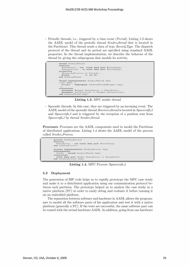
– Periodic threads, i.e., triggered by a time event (Period). Listing 1.3 shows
the AADL model of the periodic thread Sender thread that is located in
the Partition1. This thread sends a data of type Record Type. The dispatch
protocol of the thread and its period are specified using standard AADL
properties. In the thread implementation, we describe the behavior of the
thread by giving the subprogram that models its activity.�
thread Sender Threadfeatures
Data Source : out event data port Record Type ;Data ac t iva t e : in event data port Record Type ;
properties
Dispatch Protoco l => Per iod i c ;Period => 100 Ms;
end Sender Thread ;
thread implementation Sender Thread . Implc a l l s Main : {
Wrapper : subprogram Sender Thread Wrapper . impl ;} ;
connections
parameter Wrapper . Data Source −> Data Source ;parameter Data ac t iva t e −> Wrapper . Data act ivat e ;
end Sender Thread . Impl ;
� �Listing 1.3. MPC sender thread
– Sporadic threads. In this case, they are triggered by an incoming event. The
AADL model of the sporadic thread Receiver thread is located in Spacecraft 2
and Spacecraft 3 and is triggered by the reception of a position sent from
Spacecraft 1 by thread Sender thread.
Processes Processes are the AADL components used to model the Partitions
of distributed applications. Listing 1.4 shows the AADL model of the process
called Sender Process.�
process Sender Proces sfeatures
Data Source : out event data port Record Type ;end Sender Proces s ;
process implementation Sender Proces s . Implsubcomponents
Sender : thread Sender Thread . Impl ;connections
event data port Sender . Data Source −> Data Source ;end Sender Proces s . Impl ;
� �
Listing 1.4. MPC Process: Spacecraft 1
5.2 Deployment
The generation of BIP code helps us to rapidly prototype the MPC case study
and make it to a distributed application using our communication protocol be-
tween each partition. The prototype helped us to analyse the case study in a
native platform (PC) in order to easily debug and evaluate it before running it
on an embedded platform.
The separation between software and hardware in AADL allows the program-
mer to model all the software parts of his application and test it with a native
platform (generally a PC). If the tests are successful, the same software part can
be reused with the actual hardware AADL. In addition, going from one hardware
MoDELS'09 ACES-MB Workshop Proceedings
Denver, CO, USA, October 6, 2009 76

AADL BIP
Spacecraft 1 Spacecraft 2 Spacecraft 3
Components 20 4 8 8
Connectors 21 8 18 18
Lines of code 350 250 600 600
Fig. 7. Comparison between AADL & BIP
Fig. 8. Simulation of Spacecraft 1 Fig. 9. Simulation of Spacecraft 2
architecture to another is reduced (most of the time) to the modification of the
values of some few AADL properties.
In the MPC case study, we generate for each AADL partition mapped to the
processor, its corresponding description in BIP, and for each connection mapped
to the bus a network communication protocol (sender/receiver). We compile BIP
partitions and we generate an executable model. Then, we put every executable
in the native platform (PC). First, we launch a receiver executable and then
the sender executable. When the network protocol communication is initialized
between the sender and receiver, the exchange of data is started.
Once the executable model has been launched, interactive simulation and
debugging is useful for understanding the working of the distributed application.
This helped us to verifies each interaction step by step, to know which state or
port is activated, and to see the value of data received/sended. In addition, we
use observers which moves to an error state if the period of a thread exceeds
its deadline. These analysis allow to fully asses system viability, to refine and to
correct the behavior of a system.
Figure 7 summarizes the size of lines of code, number of components and con-
nectors in AADL and respectively the BIP code for the MPC case study. We split
the BIP in three parts because we generate for each Spacecraft a corresponding
BIP description system. Figures 8 and 9 show a fragment of the simulation of
Spacecraft 1 and Spacecraft 2 in the distributed platform.
MoDELS'09 ACES-MB Workshop Proceedings
Denver, CO, USA, October 6, 2009 77

6 Conclusion
In this article, we proposed a prototyping process to model and build distributed
embedded systems. We select AADL to implement this prototype. AADL allows
a clear modeling structure and provides all the required information to configure
a local application as well as distributed application.
We showed the requirements and assessments for prototyping distributed em-
bedded system using our tools chain. In addition, we provide a general method-
ology for building and translating distributed embedded systems into an ex-
ecutable implementation by using network communication protocol. The exe-
cutable application is tested for soundness, any mismatch in the application is
reported by the analysis BIP tool chain. We provide also MPC case study, which
is tested and analysed on a native platform.
In the future we are continuing to work on:
– Communication between processes can have different delay characteristics
depending on the underlying communication network. The prototyping en-
vironment should support different delay characteristics for communication
between different processes so that realistic prototypes can be built.
– Real-time clocks. This will allow real-time distributed algorithms to be im-
plemented, and timing properties to be studied.
References
1. Annex Behavior Specification SAE AS5506.2. ASSERT: http://www.assert-project.net/.3. SAE. Architecture Analysis & Design Language (standard SAE AS5506), Septem-
ber 2004, available at http://www.sae.org.4. SEI. Open Source AADL Tool Environment. http://la.sei.cmu.edu/aadlinfosite/
OpenSourceAADLToolEnvironment.html.5. SPICES: http://www.spices-itea.org/public/news.php.6. TOPCASED: http://www.topcased.org/.7. A. Basu, S. Bensalem, M. Gallien, F. Ingrand, C. Lesire, T.H. Nguyen, and
J. Sifakis. Incremental component-based construction and verification of a roboticsystem. In Proceedings of ECAI’08, Patras, Greece, 2008.
8. A. Basu, M. Bozga, and J. Sifakis. Modeling heterogeneous real-time componentsin bip. In Proceedings of SEFM ’06, Pune, India, pages 3–12. IEEE ComputerSociety, 2006.
9. A. Basu, L. Mounier, M. Poulhies, J. Pulou, and J. Sifakis. Using bip for modelingand verification of networked systems – a case study on tinyos-based networks. InProceedings of NCA’07, Cambridge, MA USA, pages 257–260, 2007.
10. S. Bensalem, M. Bozga, J. Sifakis, and T.H. Nguyen. Compositional verificationfor component-based systems and application. In Proceedings of ATVA’08, Seoul,South Korea, 2008.
11. M. Bozga, J-C. Fernandez, A. Kerbrat, and L. Mounier. Protocol verification withthe aldebaran toolset. STTT, 1:166–183, 1997.
12. M. Bozga, S. Graf, Il. Ober, Iul. Ober, and J. Sifakis. The if toolset. In Proceedingsof SFM’04, Bertinoro, Italy, volume 3185 of LNCS, pages 237–267.
MoDELS'09 ACES-MB Workshop Proceedings
Denver, CO, USA, October 6, 2009 78

13. M.Y Chkouri, A. Robert, M. Bozga, and J. Sifakis. Translating AADL into BIP -Application to the Verification of Real-Time Systems. In Models in Software Engi-neering: Workshops and Symposia at MODELS 2008, Toulouse, France, September28 - October 3, 2008., pages 5–19.
14. P. C. Clements. A survey of architecture description languages. In In Proceed-ings of the Eighth International Workshop on Software Specification and Design,Paderborn, Germany, 1996.
15. L. M. Augustin J. Vera D. Bryan D. C. Luckham, J. J. Kenney and W. Mann.Specification and analysis of system architecture using rapide. In IEEE Transac-tions on Software Engineering, volume 1 no.4, pages 336–335, 1995.
16. J. Sifakis G. Gossler. Composition for component-based modeling. Science ofComputer Programming, 55:161–183, March 2005.
17. J. Hugues, B. Zalila, L. Pautet, and F. Kordon. Rapid Prototyping of DistributedReal-Time Embedded Systems Using the AADL and Ocarina. In Proceedings ofthe 18th IEEE International Workshop on Rapid System Prototyping (RSP’07),pages 106–112, Porto Alegre, Brazil, May 2007. IEEE Computer Society Press.
18. J. Hugues, B. Zalila, L. Pautet, and F. Kordon. From the prototype to the finalembedded system using the ocarina aadl tool suite. ACM Trans. Embed. Comput.Syst., 7(4):1–25, 2008.
19. J. Magee and J. Kramer. Dynamic structure in software architectures. In In Pro-ceedings of ACM SIGSOFT’96: Fourth Symposium on the Foundations of SoftwareEngineering (FSE4), pages 3–14, 1996.
20. N. Medvidovic. A language and environment for architecture-based software de-velopment and evolution. In In Proceedings of the 1999 International Conferenceon Software Engineering, pages 44–53, 1999.
21. N. Medvidovic, P. Oreizy, J.E. Robbins, and R.N. Taylor. Using object-orientedtyping to support architectural design in the c2 style. In In Proceedings of ACMSIGSOFT201996: Fourth Symposium on the Foundations of Software Engineering(FSE4), pages 24–32. ACM Press, 1996.
22. M. Moriconi and R. A. Riemenschneider. Introduction to sadl 1.0: A language forspecifying software architecture hierarchies. In Technical Report SRI-CSL-97-01,SRI International, 1997.
23. M. Poulhies, J. Pulou, C. Rippert, and J. Sifakis. A methodology and support-ing tools for the development of component-based embedded systems. In 13thMonterey Workshop, Paris, France, volume 4888 of LNCS, pages 75–96, 2006.
24. M. Shaw, R. Deline, D.V. Klein, T.L. Ross, D.M. Young, and G. Zelesnik. Ab-stractions for software architecture and tools to support them. IEEE Transactionson Software Engineering, 21:314–335, 1995.
25. R.M. Taylor and N. Medvidovic. A classification and comparison framework forsoftware architecture description languages. IEEE Transactions on Software En-gineering, 26:70–93, 2000.
26. S. Sendall V. Crettaz, M.M. Kand and A. Strohmeier. Integrating the concernbaseapproach with sadl. In In Proceedings 4th International Conference on ModelingLanguages, Concepts, and Tools .Toronto, Canada, pages 166–181, 2001.
27. T. Vergnaud, J. Hugues, L. Pautet, and F. Kordon. PolyORB: a schizophrenicmiddleware to build versatile reliable distributed applications. In Proceedings of the9th International Conference on Reliable Software Techologies Ada-Europe 2004,volume LNCS 3063, pages 106 – 119, Palma de Mallorca, Spain, Jun.
28. S. Vestal. A cursory overview and comparison of four architecture descriptionlanguages. In Technical Report, Honeywell Technology Center, 1993.
MoDELS'09 ACES-MB Workshop Proceedings
Denver, CO, USA, October 6, 2009 79