proven - mate rov competition website
TRANSCRIPT

COMPANY MEMBERSNAME POSITIONKyle Rakos Chief Executive OfficerSanay Shah Chief Operating OfficerLuke McBee Electrical Department LeadJoshua Berg Mechanical Department Co-LeadAlex Ruffino Mechanical Department Co-LeadMatt Molo Software Department Co-LeadBen Maxfield Software Department Co-LeadBrandon Stewart Basestation HeadCharles Li Cameras & Sensors Co-HeadJason King Cameras & Sensors Co-HeadRyan McBee Logic Boards & Embedded Programming HeadRodolfo Leiva Power & Movement Co-HeadCarolyn Lewelling Power & Movement Co-Head/Sponsorship HeadTeal Dowd Structures & Connectors Co-HeadSamuel Deghuee Structures & Connectors Co-HeadJoe Pejril Tools & Actuation HeadTyler Stagge Pilot/Mechanical DepartmentHenry Shi Technical WriterAlex Gebhardt Mechanical DepartmentAmandeep Singh Mechanical DepartmentBayley Clausen Mechanical DepartmentBen Hutchins Mechanical DepartmentDaniel Schillizzi Mechanical/Electrical DepartmentEnle Choo Mechanical DepartmentJacob Cottrell Mechanical DepartmentJonathan Kline Mechanical DepartmentKatherine Mao Mechanical DepartmentLogan Walters Mechanical DepartmentMonica Mah Mechanical DepartmentReed Trende Mechanical DepartmentRohit Srivastava Mechanical DepartmentSeth Emond Mechanical DepartmentAlan Han Electrical DepartmentDavid Bustamante Electrical DepartmentJames Scholl Electrical DepartmentJessica Chin Electrical DepartmentJohn Bramkamp Electrical DepartmentNicholas Loffredo Electrical DepartmentReshef Elisha Electrical DepartmentRomita Biswas Electrical DepartmentSreyas Mirthipati Electrical DepartmentXi Wu Electrical DepartmentAndrew Bostock Software DepartmentIan Sibley Software DepartmentJoey Danial Software DepartmentKeith Aylwin Software DepartmentKendal Norman Software DepartmentSam Jenkins Software DepartmentSamuale Yigrem Software DepartmentZidaan Dutta Software Department
Mentors: None
PROVENROBOTICS
West Lafayette, IN USAPURDUE UNIVERSITY
2017 Technical DocumentationPort Cities of the Future: Commerce,
Entertainment, Health, and Safety
ROV CEPHALOPODCommerce, Entertainment Platforms, Health,And Loop Operation Purdue Original Device

2
Proven Robotics
I. Introduction 3Abstract 3
II. Safety 4A. Safety Philosophy 4B. Safety Standards 4C. Safety Features 4
III. Mechanical Design Rationale 5A. Mechanical Overview 5B. Frame 5C. Power Distribution Box 6D. Electronics Tube 6E. Main Camera Tube 7F. Secondary Camera Housing 7G. Buoyancy 7H. Basestation 8
IV. Mission Tools Rationale 9A. Manipulator 9B. Fountain Installation Tool 9C. Valve Turner 9D. Sediment Collector Tool 10E. Payload Basket 10F. Bluetooth Sensor 10G. Power Connector Tool 11H. Buoy Marker 11I. Camera Measurement Tool 11
V. Electrical Design Rationale 12A. Electrical Overview 12B. Power Brick Board 12C. Power Distribution Board 12D. Blue Robotics T200 Thrusters 13E. Raspberry Pi 13F. Shield 14G. Backplane 14
VI. Software Design Rationale 15A. Software Philosophy & Overview 15B. BattleStation 15C. Tether Communications 16D. Embedded Communications 16E. Movement Control 16
VII. Logistics 17A. Company Organization 17B. Project Management 17C. Project Costing and Budget 18
VIII. Conclusion 19A. Testing and Troubleshooting 19B. Challenges Testing and Troubleshooting 19C. Lessons Learned and Skills Gained 19D. Future Improvements 20E. Reflections 20
IX. Appendix 21A. Safety Checklist 21B. System Interconnect Diagrams 22C. Acknowledgments 24D. References 25
Tab le o f Conten ts

3
ROV Cephalopod Technical Documentation
AbstractProven Robotics has developed a Remotely Operated underwater Vehicle (ROV) to satisfy the Port of Long Beach’s request for an ROV that can perform a variety of tasks in various conditions. The tireless work of the 50-person company has resulted in ROV Cephalopod. This ROV can perform Hyperloop construction, conduct light and water show maintenance, collect and remediate contaminated sediments, and map the locations of potentially hazardous cargo containers. ROV Cephalopod is designed, built, and tested in-house to ensure full mission success. Proven Robotics is organized into mechanical, electrical, software, and administrative departments to focus on particular specialties. Additionally, cross-disciplinary project groups have been formed to focus on specific vehicle systems, to strengthen communication, and to better coordinate the 7,000 person-hours of work done on the ROV. Safety, planning, and budgetary requirements guided all design and build decisions throughout the year. An iterative design, build, and test process was utilized for mission tools to ensure each task could efficiently be completed. ROV Cephalopod was optimized for both minimal size and weight to fulfill mission requirements. Designs resulted in the use of custom printed circuit boards (PCBs), a waterjet-created frame, various mission specific 3D printed tools, and eight Blue Robotics T200 Thrusters. ROV Cephalopod meets all stipulations for the competition and is equipped with necessary tools to accomplish each task. The following technical document reports the design rationale and company processes required to produce ROV Cephalopod.
I . INTRODUCT ION
Proven Robotics 2017 Team

4
Proven Robotics
A. Safety PhilosophyProven Robotics’ foremost priority is to ensure employee safety. Maintaining a safe work environment not only prevents accidents and injuries, but it also provides company members with a comfortable and reliable space to work. The company always considers the safety ramifications of a process or action undertaken within the lab and during product use. Experienced employees oversee and advise the work done by new hires to ensure the overall safety of each worker.
B. Safety StandardsThe company employed several safety rules during construction of ROV Cephalopod. In the lab, Proven Robotics ensures the availability of personal protective equipment (PPE), such as face masks, safety glasses, an emergency eyewash, shower stations, and first aid kits. The company lab is located on the premises of Purdue University, thus providing convenient and safe access for all employees. Additionally, employees are expected to follow the stricter of the two safety standards (Proven Robotics or on-site rules) at all work locations (Ref. 11).
Basic safety rules are clearly posted inside Proven Robotics’ lab with experienced members available to answer any questions and provide guidance. Additional training is required for more specific tools such as the company-owned drill press, bandsaw, belt sander, and grinding wheel. During power equipment use, ANSI-approved eye protection is utilized. Furthermore, electrical technicians are provided with an activated charcoal filter for use while soldering.
C. Safety FeaturesROV Cephalopod is designed with several built-in safety features such as a master fuse, individually resettable thruster fuses, thruster shrouds, warning labels for potentially dangerous components, and rounded frame edges. Furthermore, the company follows a safety checklist (Appendix part A) to maintain a low risk environment before launching the vehicle.
ROV Cephalopod is equipped with advanced software safety features to ensure the pilot is never left with a dangerous moving vehicle. Before the pilot takes control of the vehicle, diagnostic information is displayed on the computer screen to ensure that all components are operating properly. Once the pilot and co-pilot are assured of a correctly operating ROV, the pilot instructs the pool-side technicians to release the vehicle. During operation, the ROV continues to give the pilot and co-pilot thruster and system information to ensure intended operation. If at any point a system stops working, the pilot or co-pilot may disarm the ROV. Loss of communication also disarms the ROV, putting it into a safe state with no moving parts.
I I . Sa fe ty
Fig. 1 - Employees debugging electronics
in the lab
Fig. 2 - Operating the waterjet for the frame's creation
Fig. 3 - ROV Cephalopod gets ready for its
first pool test

5
ROV Cephalopod Technical Documentation
A. Mechanical OverviewThe mechanical components of ROV Cephalopod are designed around the mission tools to make sure all missions can be executed successfully without components, such as the frame, being in the way. All mechanical aspects were thoroughly discussed before designs were finalized. Following an internal review process amongst the mechanical department, all designs were converted to SOLIDWORKS models. Stress analysis was used to fine-tune the CAD models before a formal design review occurred amongst all departments. After this cross-disciplinary feedback, prototypes were tested under conditions similar to the mission’s, which provided insight in order to fine tune the final mechanical creations. Additionally, every watertight enclosure was repeatedly tested for at least 20 minutes at a minimum depth of 13 meters in Proven Robotics’ custom pressure testing vessel, well beyond the expected mission time and depth. 3D printed parts were used extensively in order to allow rapid prototyping of various complex shapes that would be difficult to machine. All mechanical systems were newly designed and built by Proven Robotics to ensure that the optimal solution was created. The resulting vehicle and tether has a mass of 15.5 kg and the ROV is 52 cm x 50 cm x 36 cm; therefore, both the size and weight are well within the smallest MATE requirements.
B. Frame ROV Cephalopod’s frame (Fig. 4) consists of two main vertical plates (Fig. 5) connected by five supporting horizontal plates (Fig. 6). Each horizontal plate is joined by hybrid mortise and tenon joints firmly secured with a bolt. The mortise and tenon joints reduce shear load on the bolts and perform well under tensile load. This design was chosen due to the success of Proven Robotics’ previous ROV Maelstrom, which employed the vertical plate system in order to optimize volumetric efficiency while allowing internal augmentation. Volumetric efficiency was further improved by mounting the central axis of the vertical thrusters in line with the plane of the frame’s side plates, such that exactly half of the thruster was inside the frame and half was outside, which reduced outer dimensions while still ensuring enough internal space. Additionally, Proven Robotics took mass into consideration when selecting a building material for the frame, which can be a significant portion of the total mass. The company considered plastics, such as high-density polyethylene (HDPE) and polycarbonate, previously used aluminum 6061-T6, and aluminum 7075-T6 materials to have a low mass, yet strong and rigid frame. Previous years’ calculations found that aluminum 6061-T6 is better than the plastic alternatives due to its ability to sustain most material removal while maintaining overall strength. However, the tensile strength and yield point of aluminum 7075-T6 is nearly two times greater than aluminum 6061-T6 (Ref. 4), allowing for less material in the frame. Although aluminum 7075-T6 is 84% (Ref. 1 & 2)
I I I . Mechan ica l Des ign Ra t iona le
Fig. 4 - Complete frame rendering
Fig. 5 - One of the two vertical plates
Fig. 6 - One of the five horizontal plates

6
Proven Robotics
more expensive than aluminum 6061-T6, the greater strength allowed for a smaller mass.
In some pieces of the frame, up to 81% of the material was removed. Finite element analysis (FEA) was used to analyze the frame throughout the design process to ensure the structural integrity of the ROV (Fig. 7). The resulting frame has a mass of 1.5 kg in air and is one of the lightest frames in Proven Robotics’ history. Another benefit of a lighter frame is less buoyant foam material needs to be added in order to achieve neutral buoyancy, allowing for smaller overall volume. The resulting design was cut using a waterjet by the company and anodized for a professional, durable, and anti-corrosive finish.
C. Power Distribution Box The Power Distribution Box (Fig. 8) contains the Power Distribution Board (see Section V part C) and twelve Electronic Speed Controllers (ESCs) for tool and thruster control. These are separate from the Electronics Tube, because there is more surface area through which to dissipate heat and add mount connectors. Fourteen 16-mm Binder connectors (Ref. 3) are used for output power, data, tool control, and thruster control with one Subconn connector (Ref. 13) used for the input power. The box is made from five aluminum 6061-T6 plates that are welded together with a top lid plate constructed of polycarbonate. The lid uses a face seal of an O-ring and twenty evenly spaced screws. The transparent polycarbonate plate allows visual inspection of the electronics for proper operation and leak detection. Internally, the Power Distribution Board is directly attached to the aluminum bottom so the entire box acts as a heat sink for the power system. The ESCs are mounted on internal 3.175-mm aluminum plates for additional heat sinking then are directly attached to the box.
D. Electronics Tube The purpose of the Electronics Tube (Fig. 9) is to house the main electronics, which are stacked inside the tube. Proven Robotics shortened the electronics tube compared to last year due to smaller electronics to a total size of 12.7-cm height and 15.24-cm diameter. The smaller height reduced concerns about tube deformation, allowing Proven Robotics to eliminate the need for aluminum couplings. The two end caps were simply fitted directly in each end of the tube. Both end caps were machined in-house using a manual lathe. Then a CNC mill, with machine code generated in CATIA, was used to drill holes for the underwater connectors, which were later manually tapped. The bottom end cap contains eight 16-mm Binder connectors for tools, cameras, tether, one pressure sensor, and one pressure relief valve. The pressure relief valve makes sealing the tube easier and more secure by allowing air to escape and reducing the internal pressure resisting the end caps while placing them on the tube. This reduces the chance of rapid decompression during ascent, which may unexpectedly release an end cap. The Electronics Tube maintains its watertight seal by using
Fig. 8 - PowerDistribution Box
Fig. 9 - Electronics Tube
Fig. 10 - ElectronicsTube bottom end cap
Fig. 7 - Visual representation of frame
deflection under an extreme load condition

7
ROV Cephalopod Technical Documentation
two X-profile O-rings on each end cap. This provides redundancy that significantly decreases the chance of failure. The tube is attached to the ROV using four thumbscrews to clamp the bottom end cap flanges to the frame plate (Fig. 10). This attachment method allows for secure placement and quick removal of the end cap and quick removal of the Electronics Tube, which is attached to the end cap.
E. Main Camera TubeThe Main Camera Tube (Fig. 11) is a polycarbonate tube with two aluminum end caps that contains the Main Camera Board. This housing design is an improved version of the previous year’s design. The tube’s diameter decreased from 7.6 cm last year to 5.0 cm this year, reducing the ROV’s total size. Moreover, a servo motor is attached directly to the circuit board and the servo motor shaft is attached to the end cap. The fully enclosed design allows 180 degrees of camera tilt while maintaining a waterproof seal. This tilt provides a wider field of view. Light emitting diodes (LEDs) on the board are used to illuminate the environment and act as a simulated Raman spectrometer.
The aluminum end caps were machined in-house with a manual lathe. Each cap has two grooves for the X-profile O-rings, which were chosen in the same manner as the Electronics Tube O-rings. In order to prevent the camera from being accidentally rotated, each end cap has its outer edge sanded and fitted in matching D-shafts on the frame. In addition, one end cap has a tapped through hole for a 16-mm Binder connector. The other end cap has a small indent used to align the servo motor when it is being attached to the cap.
F. Secondary Camera HousingsThe purpose of the secondary cameras are to provide the pilot with a direct view of tools not easily seen by the main camera. There are three Secondary Camera Housings (Fig. 12) on the ROV, one on the starboard side looking forward at the Power Connector Tool, one on the port side looking backward at the Sediment Collector, and one looking down for site mapping. The design for the housings centers on easy manufacturability to reduce cost; therefore, the majority of the parts are 3D printed.
The cameras contain side plates, a back plate, and frame mount plate. Where needed, the camera angle can be adjusted by moving the mounting side plates for fine tuned adjustments. The camera itself is coated in marine epoxy, and has a piece of polycarbonate epoxied to the lens. This creates a permanent waterproof environment without any blurriness that the epoxy would cause if the lens was coated.
G. Buoyancy and BallastThe primary function of the foam buoyancy system is to make the ROV neutrally buoyant and stable. To achieve this, measurements of the ROV’s cumulative mass and volume were used to calculate the total volume of foam required (4200 cm3) to provide a total buoyant force equal to the vehicle’s underwater weight, foam included. A series of foam parts
Fig. 11 - Main Camera Tube with exploded brackets
Fig. 12 - SecondaryCamera Housing
Fig. 13 - Highlight offoam parts (in black)
Fig. 14Purple: Original COM & COBRed: Foam COM & COBGreen: Final COM & COB
COB: Center of Buoyancy (up arrow)COM: Center of Mass (down arrow)
8
Proven Robotics
(Fig. 13) with said total volume were then carefully modeled so as to bring the vehicle’s calculated center of buoyancy to the center of the thruster configuration in the horizontal plane and as high as possible in the vertical direction (Fig. 14) so as to provide maximum control and stability. The final three parts were then machined from HCP 30 foam using a gantry sheet router. Finally, additional ballast was used to bring the ROV’s center of mass inline vertically with its center of buoyancy and the volume of the foam was refined to ensure neutral buoyancy.
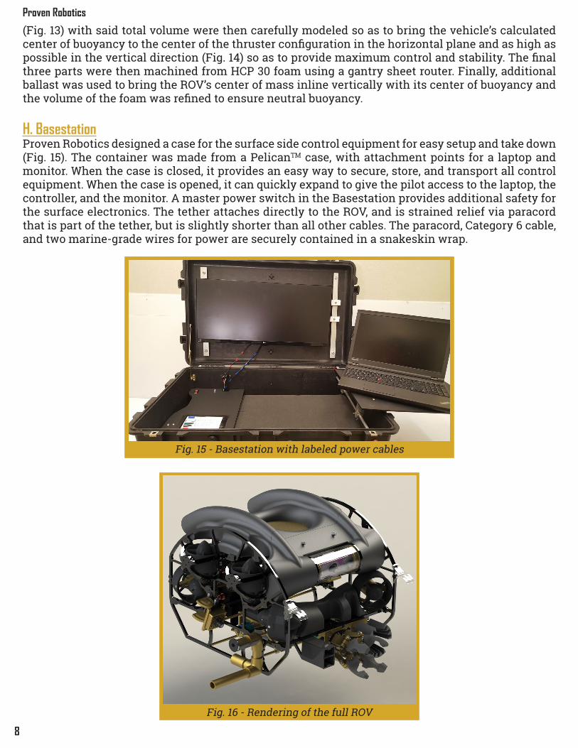
H. BasestationProven Robotics designed a case for the surface side control equipment for easy setup and take down (Fig. 15). The container was made from a PelicanTM case, with attachment points for a laptop and monitor. When the case is closed, it provides an easy way to secure, store, and transport all control equipment. When the case is opened, it can quickly expand to give the pilot access to the laptop, the controller, and the monitor. A master power switch in the Basestation provides additional safety for the surface electronics. The tether attaches directly to the ROV, and is strained relief via paracord that is part of the tether, but is slightly shorter than all other cables. The paracord, Category 6 cable, and two marine-grade wires for power are securely contained in a snakeskin wrap.
Fig. 15 - Basestation with labeled power cables
Fig. 16 - Rendering of the full ROV

9
ROV Cephalopod Technical Documentation
A. ManipulatorThe Manipulator (Fig. 17) is designed to be reliable and easy to operate, as well as multipurpose in the interest of reducing the total number of required tools and weight. These requirements result in a design with only one degree of freedom, but thanks to its unique “quad pincer” design can manipulate a wide variety of objects and pipes in multiple orientations. The Manipulator is driven by a Blue Robotics M200 waterproof motor and a simple 6.35-mm Acme rod and nut system. Most of the Manipulator’s mechanical components are 3D printed in polylactic acid (PLA), in addition to several laser-cut HDPE linkages and an aluminum 7075-T6-created back plate, all held together at the joints with shoulder bolts and nylon washers. The end effectors are replaceable, which allowed easy refinement over five iterations, resulting in a design that is both multipurpose and self-aligning. Moreover, they are dipped in a rubberized coating called Plasti Dip® to increase their coefficient of friction and thus grip. Finally, the Manipulator mounts to the ROV with a custom quick-release aluminum 6061-T6 bracket enabling compact storage and quick setup. The Manipulator is used in the Commerce task for maneuvering the rebar pipes, releasing the chain pin, transporting the hose, and retrieving the positioning beacons. It is used in the Entertainment task for disconnecting the power cable and moving the locking mechanism. Finally, in the Health task, the Manipulator is used to collect clams and place the cap over the contaminated sediment. B. Fountain Installation ToolThe Fountain Installation Tool (Fig. 19) exists as a specialized component designed to manipulate the unique geometry of the fountain in the Entertainment task while taking advantage of otherwise unused space on the underside of the ROV. Four 6.35-mm diameter aluminum rods secure the tool to the vehicle’s frame, while also supporting two aluminum plates and guiding the actuation of two clamps designed to align and grasp the fountain. Only one of these PLA, 3D printed clamps is mobile, powered by a Blue Robotics M100 motor via an Acme rod and nut system, similar to that of the Manipulator. Operation of the tool requires use of the Main Camera, tilted towards the bottom of its range. C. Valve TurnerThe Valve Turner’s function is to open and close the valve in the Entertainment task. A self-aligning end effector (Fig. 20) was designed and 3D printed to conform to the shape of the outside of the valve. This end effector is rotated by a Blue Robotics M100 motor. To ensure visual confirmation of the valve’s rotation, this end effector, which was originally completely enclosed, is divided into three separate protrusions, centered at equal offsets. Multiple versions of this end effector were designed and manufactured so as to enable the ROV to rotate valves
I V . M iss ion Too ls Ra t iona le
Fig. 17 - The Manipulator
Fig. 18 - Early variant of "quad pincer" design
Fig. 19 - Fountain Installation Tool
Fig. 20 - Valve Turner with multiple valve geometries

10
Proven Robotics
of various geometries. Finally, the tool itself mounts to the ROV with a custom aluminum quick-release bracket, nearly identical to that of the Manipulator. This enables the tool to be removed for compact storage and secured quickly to the vehicle via quick-release pins prior to operation. D. Sediment Collector ToolThe Sediment Collector Tool (Fig. 21) is designed to collect sediment as part of the Health task. Originally, two designs were considered. The first, inspired by a slush collector for ice fishing, had flaps at the front that folded only into the body of the tube. Pushing into the sediment, the flaps would open and allow sediment in, and then close on retraction to prevent the sediment from leaving. The second design was an Archimedes screw, where a driven auger rotated within a tight tube to suck in the sediment. The Archimedes screw design was able to exert a force pulling in on the sediment as well as a pressure differential, but also had a greater surface area and thus more frictional force. For this reason, it was determined that the slush collector would work better with a viscous sediment, but the Archimedes screw would be better with a more fluid sediment. After testing, Proven Robotics found that the sediment was very viscous, and determined that the slush collector would be a better option.
Further research revealed that a predecessor to Proven Robotics, Aperture Aquatics, designed a successful agar collector with no moving parts. The sediment collector was a tube with a one-way valve on the back, meaning that water could escape the tube as the sediment was pushed in, but that a pressure differential would keep the sediment from falling out of the tube. The lack of moving parts makes this design easier to build and less likely to fail. Using this inspiration, the Sediment Collector Tool was created from a 15-cm long polycarbonate tube, chamfered at the end to pierce the agar (with an appropriate safety sticker on the tool) and a 3D printed top cap serving as a mounting mechanism and place for the one-way valve. The agar is released on the surface by an employee who uses a long, thin rod to puncture the agar and break the seal.
E. Payload BasketThe Payload Basket (Fig. 22) is separate from the ROV and allows the surface crew to raise and lower equipment and samples without requiring the vehicle to surface, saving significant amounts of travel time, especially at depth. The Payload Basket is designed to minimize additional mass and volume; it is assembled from four lightweight aluminum beams and aluminum standoffs to allow the Payload Basket to mate upside down with the underside of the ROV during storage. The standoffs act as feet, elevating the basket, while a polystyrene net holds payloads deposited by the vehicle.
F. Bluetooth SensorBased on The MATE Center’s experimental estimates (Ref. 8), the Bluetooth sensor must be within 10 cm of the transmitter while underwater to be effective. Knowing this, the Bluetooth Sensor tool (Fig. 23) was designed to protrude as far forward from the ROV as possible while not interfering
Fig. 21 - SedimentCollector Tool
Fig. 22 - Payload Basket
Fig. 23 - Bluetooth Sensor

11
ROV Cephalopod Technical Documentation
with other tools. The tool is designed to be a box with an open side and a small hole in the back face for wires. The box is attached to an arm, which is then connected to the frame. The Bluetooth receiver is placed in the box, with wires being fed through the hole. All electrical components are then potted in place, creating a waterproof environment.
G. Power Connector ToolIn the design of this tool, Proven Robotics considered the previous year’s mission, which required picking up an item identical to the power connector. The same successful design was utilized: a protrusion sticks into the power connector while a magnet secures the power connector in place for the Entertainment task. This year, the company 3D printed the tool into a unique shape (Fig. 24) in order to self-align the power connector as the ROV moved to pick it up. In testing, the tool worked as desired; however, during mission runs, the tool itself continuously snapped off of the ROV due to an insufficiently strong mounting mechanism for the 3D printed part. In the final iteration of the tool, the company resorted to previous year’s design, which used polyvinyl chloride (PVC) tubing (Fig. 25). The self-aligning feature of the 3D printed design turned out to be not as critical in the insertion of the power connector.
H. Buoy MarkerThe Buoy Marker (Fig. 26) is designed to mark the most hazardous shipping container as part of the Safety task while being as simple and reliable as possible. The buoy mounts to the Power Connector Tool, which secures it magnetically for transport and aids in alignment with the U-bolt to which the buoy attaches. This dual functionality reduces both the total number of tools required to complete the mission and the total number of cameras required to see them. The buoy attaches to the container via a simple, gravity-fed catch mechanism, manufactured from aluminum plates and mounted to a PLA, 3D printed body. Once the ROV detaches from the buoy with slight lateral motion, the roughly spherical foam float is released and ascends to the surface, connected via 7 m of 38-kg test, braided fishing line.
I. Camera Measurement ToolThe Camera Measurement Tool (Fig. 27) is software only feature, run by the co-pilot to measure the distance between cargo containers for the safety task. A snapshot of the ROV's bottom facing camera is taken directly over the cargo containers. A reference line is drawn on the long edge of a container. Knowing the exact measurement of the container, the software can measure distances in pixels and convert them to a distance in centimeters. The measurement tool can be quickly accessed in the BattleStation. A software approach was taken instead of a mechanical or electrical approach for its easy implementation and with the benefit of no added mass. While this method works well, it assumes all objects being measured are equidistant from the camera. This requires the ROV to position itself in a way that makes this as accurate an estimate as possible.
Fig. 26 - Buoy Marker magnetically attached to the Power Connector Tool
Fig. 27 - Red Reference line with blue measurement
Fig. 25 - Simplified PVC Power Connector Tool
Fig. 24 - First Power Connector Tool Design

12
Proven Robotics
A. Electrical OverviewROV Cephalopod’s electronics are designed for reliability over the lifespan of the ROV. Control of the ROV begins with the surface electronics, which include a laptop computer, external monitor, and a 48-V power supply. Control data is sent directly from the laptop’s Ethernet port to the ROV’s Electronics Tube using a Category 6 cable, which provides noise immunity and the ability to handle a high data throughput. 48 V is also sent down to the ROV using two 2.05-mm diameter marine-grade wires in line with a 20-A fuse. The 48 V enters the Power Distribution Box and is converted to 12 V on the three Power Brick Boards. The 12-V power bus is then distributed by the Power Distribution Board to the eight thrusters, the motorized tools, and the Electronics Tube. The Power Distribution Board also controls the thrusters and motorized tools. The Electronics Tube contains a stack of circuit boards that handle the computational needs of ROV Cephalopod. First is the Backplane Board, which routes the external connections to the rest of the circuit boards. The Shield Board connects to the Backplane Board and contains power converters and other necessary integrated circuits (ICs) to assist with task completion. Finally, the Raspberry Pi attaches to the Shield Board via header pins to provide processing capabilities for the ROV. The Raspberry Pi is also responsible for processing four HD ELP-USB100W04H-L36 USB cameras placed on the ROV and the Ethernet connection from the tether. All circuit boards on the ROV, with the exception of the Raspberry Pi, were designed with EAGLE PCB Design and Schematic software and populated in-house. B. Power Brick BoardThe Power Brick Board (Fig. 28) is used to convert tether power from 48 V to 12 V. Each board contains a single Murata DRQ-12/50-L48 series 600-W, quarter-brick buck converter with a typical efficiency of 96% (Ref. 10) with support for load sharing. Linear regulators were considered in the past; however, after successfully employing a buck converter design last year, the company realized that it could successfully design a primary power conversion system using buck converters to improve efficiency and reduce heat dissipation. Only one quarter-brick converter per board was utilized in order to allow modular testing before being combined in the Power Distribution Board.
C. Power Distribution BoardThe Power Distribution Board (Fig. 29) interfaces with three individual Power Brick Boards to supply the necessary power to the entire ROV system. The single 12-V power bus evenly sources current from the three individual bricks with load sharing. Load sharing was deemed to be an important
V . E l ec tr ica l Des ign Ra t iona le
Fig. 28 - Power Brick Board Fig. 29 - Power Distribution Board

13
ROV Cephalopod Technical Documentation
new feature for the ROV this year in order to remove concerns of uneven current draw from specific tools or motors. Special care was paid to the layout of this board as parallel voltage supplies have specific impedance requirements. Additionally, since the 12-V bus was capable of outputting up to 1800 W, a four-layer PCB was created with 0.071-mm thick copper (twice the normal amount) in order to handle the increased current requirements. While a four-layer board is more complicated and error prone than previously utilized two-layer boards, its use was justified in order to enable a load sharing power system in a confined area. The Power Distribution Board additionally receives Inter-Integrated Circuit (I2C) commands from the Raspberry Pi, which are then converted to Pulse Width Modulation (PWM) commands with an IC. The resulting PWM commands control the eight thrusters and three Blue Robotics motors for tool movement. By keeping the control and power of the high-current motors on the Power Distribution Board, there is less concern of switching noise affecting command electronics and a reduced need for extra, high-current carrying wires.
D. Blue Robotics T200 ThrustersROV Cephalopod utilizes eight thrusters for full movement in all 3 translational and all 3 rotational axes. Full rotational control was deemed necessary for easier navigation around objects and tool alignment. Four thrusters are positioned vertically, and the other four, horizontally with offsets of 20°. Previous years’ MATLAB simulations (Fig. 30) proved this to be the best balance between turn speed and horizontal speed. Proven Robotics again made use of Blue Robotics T200 Thrusters (Fig. 31) for their cost, performance, and compact size. The Blue Robotics thrusters are more reliably than any in-house design, thus justifying a commercial choice. They provide up to 34.81 N of thrust when operating at 12 V (Ref. 14). Additionally, the thrusters are small in volume, enabling a compact, maneuverable vehicle. The thrusters are controlled using standard ESCs. The main requirements of the ESCs were to source up to 20 A while maintaining as small a footprint as possible in order to fit inside the Power Distribution Box. Therefore, the Afro Race Spec Mini 20-A ESCs were tested and ultimately chosen. Alternative ESCs were tested and also worked; however, they were more expensive without providing additional benefits. E. Raspberry PiThis year the company chose to use a Raspberry Pi 3 Model B (Fig. 32) for the main controller instead of the previously utilized STM32 microcontroller. A Raspberry Pi was purchased because of its more complex design for a full processor and its established software drivers and libraries. This change enables easier interfacing to the ROV over a standard Ethernet connection and Internet Protocol (IP). Additionally, the four USB 2.0 ports allow Proven Robotics to use USB cameras, which are cheaper and smaller than the Ethernet cameras used in the previous year.
Fig. 31 - Blue RoboticsT200 Thruster
Fig. 32 - Raspberry Pi Model B
Fig. 30 - MATLAB Simulation of Horizontal
and Vertical Thrust vs Thruster Mount Angles

14
Proven Robotics
Changing to a Raspberry Pi also improved how software was managed and updated. Since a full Linux operating system was capable of running on a Raspberry Pi, a plethora of new features became available. The majority of the code was written in Python, which allows for quicker unit testing and easier management of a large code base than lower level C. Furthermore, ROV Cephalopod is able to have its code updated while in the water because of remote login capabilities. This has allowed for rapid fixes and iterative improvements while testing the ROV in the water.
F. Shield BoardThe Shield Board’s (Fig. 34) main function is to support the Raspberry Pi by connecting its signal lines to the rest of the ROV and providing it with 5 V using a buck converter circuit. The Shield Board contains connectors for attaching the Raspberry Pi, the transistors to drive LEDs for the Main Camera Tube and Bluetooth Sensor tool, and the inertial measurement unit (IMU). The Shield Board is equipped with many debugging pins for easier testing and validation. The Shield Board routes all necessary power and communication lines to the Backplane Board using board-to-board connectors for external tools. An included safety feature is using different pin counts for the Backplane Board connectors, preventing the Shield Board from being inserted backwards.
G. Backplane BoardThe Backplane Board (Fig. 35) contains connectors to attach the Shield Board to the Backplane Board and additional connectors to attach the Backplane Board to the water proof connectors in the Electronics Tube end cap. By separating the Backplane Board’s functionality from the Shield Board, the company is able to remove the Raspberry Pi and Shield Board stack for testing outside of the ROV while the Backplane Board remains more permanently on the end cap. Previously, it was difficult and time consuming to disconnect and reconnect all of the connectors every time the main electronics needed testing separately from the ROV.
Fig. 33 - Full Raspberry Pi, Shield Board,and Backplane Board stack
Fig. 34 - Shield Board Fig. 35 - Backplane Board

15
ROV Cephalopod Technical Documentation
A. Software Philosophy & OverviewThe software philosophy for ROV Cephalopod is to make an architecture that leverages the power of current technology to facilitate quick development and easy debugging. By using these traits to their full potential, Proven Robotics made the software nimble and flexible, which is suited well for developing a product on a tight schedule. GitHub was utilized to simultaneously enable the entire software department to work on the codebase while ensuring the software’s history was recorded. The main component of ROV Cephalopod’s software architecture is its use of a client-server model for connecting to and controlling the ROV. A transmission control protocol (TCP) connection is established between the client (BattleStation) and the server (ROV Cephalopod’s Raspberry Pi). Then JavaScript, VueJS, and other web technologies enable WebSocket connections to communicate quickly and asynchronously with the ROV. Controls are sent to the ROV and diagnostic data and camera streams are viewed by the pilot through a connected browser client. Inside the ROV, a Python-based Flask server handles the inbound and outbound socket communications, controlling and directing information. Proven Robotics leverages the multiple cores of the Raspberry Pi to run all needed functions in near real time. View the Appendix part B for a diagram of the software flowchart.
B. BattleStationThe BattleStation (Fig. 36) is Proven Robotics’ custom designed surface-side software. The BattleStation allows the pilot to control the ROV through an Xbox-style controller and displays diagnostic information, tool readings, mission information, and camera feeds. This year, the company switched to a web-based interface using HTML, JavaScript and CSS. Using the VueJS framework for making reusable components, the BattleStation could be created quickly. This web-based interface is packaged with the Electron framework, turning it into a more fully featured desktop application. Different designs were iterated through, in search of maximizing usability while being aesthetically pleasing. Information such as the pilot’s control and tool configurations is sent via WebSockets to the ROV’s Raspberry Pi 100 times a second. The ROV relays data back to the BattleStation, and its components are updated.
V I . So f tware Des ign Ra t iona le
Fig. 36 - Main BattleStation View

16
Proven Robotics
The BattleStation provides a few specific features that assist the pilot and co-pilot in completing the mission. A mission task list and timer ensure all tasks will be completed on time. IMU sensor data is displayed so the pilot can understand the orientation of the ROV absent visual assistance from the mission items. Controller settings and tool configuration can be changed to adapt to different conditions. While the information displayed on the BattleStation is useful, the main focus is the cameras. The Basestation consists of a laptop and extra-wide screen, allowing two camera feeds to be displayed at once without sacrificing space. Video feeds can also be changed to view any camera and snapshotted for review at a later time. The snapshot feature is important for the previously mentioned Camera Measurement Tool.
C. Tether CommunicationsThe Ethernet port on the Raspberry Pi shares the same data bus as the four USB ports. Therefore, camera and data usage must be kept at a minimum. The active camera streams make up the majority of the data, while the controls and status data are negligible. Therefore, the camera streams are dynamically suspended and resumed depending on which camera view the pilot wants to see at the time. When a camera stream is chosen, the stream is sent over a dedicated port using TCP. The controls and status data is packaged in JavaScript Object Notation (JSON) and sent over WebSockets on the tether.
D. Embedded CommunicationThe Raspberry Pi directly communicates with the servo motor, pressure sensor, IMU, and Bluetooth Sensor. A PWM signal is generated by the Raspberry Pi to control the servo for the Main Camera Tube while I2C is used to communicate with the IMU and pressure sensor. The Bluetooth sensor uses serial communication interface to send results to the Raspberry Pi and receive commands from the Pi. The Raspberry Pi also indirectly communicates with the thrusters and motorized tools by sending I2C commands to the PCA9685 I2C-to-PWM converter chip. The output PWM signal from the PCA9685 chip is then sent to the ESCs, which then control the thrusters and tool motors. A separate chip to generate the PWM signals ensures the number of tools and motors are not limited by the number of pins on the Raspberry Pi.
E. Movement ControlROV Cephalopod is controlled via a standard Xbox-style controller. The controls are similar to conventional driving games. Movement precision can dynamically be changed in the desired axis throughout the mission on the BattleStation. Proven Robotics again implemented an advanced thrust mapping algorithm that uses a linear transformation on the six-dimensional force and torque vectors, to produce an eight-dimensional thruster output. This allows for changing the transformation vector in case of thruster failure. This means the ROV can still be controllable with a simple, manual change. Proven Robotics continuously worked on the thruster algorithm to provide even more options. Progress has been made on a new algorithm that enables ROV Cephalopod to automatically pivot about a point and automatically compensate for uneven or broken thrusters.

17
ROV Cephalopod Technical Documentation
A. Company OrganizationProven Robotics is composed of three technical departments and six interconnected project groups. Each department—mechanical, electrical, and software—has a department lead who reports directly to the CEO. Their jobs are to ensure competencies in the various technical disciplines of the company. Additionally, this year saw the introduction of project groups, which have representatives from each of the three technical departments. These groups are Basestation, Cameras & Sensors, Logic Boards & Embedded Programming, Power & Movement, Structures & Connectors, and Tools & Actuation. These groups were created to better help employees focus on a specific aspect of the ROV instead of merely their technical expertise. This system was created as a response to integration failures from three distinct technical systems that occurred last year. The project group system focuses on the ultimate results of ROV systems and not merely isolated electrical, mechanical, or software components. In addition to the three technical departments and project groups, the CEO leads an administrative group composed of the COO, Technical Writer, and sponsorship coordinators. B. Project ManagementProven Robotics uses a Gantt chart to form the overarching deadlines during the production of ROV Cephalopod. The schedule is divided into four main phases: training, designing, building, and testing. During the training phase, new employees are recruited and focus on SOLIDWORKS design, EAGLE PCB design, or Raspberry Pi and Python software depending on their interest. During this time a Failure Mode and Effects Analysis (FMEA) is undertaken in order to figure out areas that went wrong last year and how to avoid them in the future. After training, the company moves into the design phase. Before mission specifications are released, the company focuses on ROV core components such as the frame, cameras, power conversion, and actuation. Once the company receives the full mission specifications, the mission tools are designed, and the previous designs are fine-tuned. The design phase is particularly stressed to ensure any oversights in the future are minimized. First, ideas are brainstormed and discussed before they are drafted in SOLIDWORKS or EAGLE. The company performed a “pre-mortem” in the form of another FMEA. This FMEA predicts potential points of failure in the design of the new ROV, gives the company a tool to recognize failure points, and mitigates them before they appear. Finally, all current and former employees conduct a formal design review before moving into the building phase. In the building phase, the company simultaneously manufactures the frame and tools, prints and then populates the PCBs, and writes the software. Components on the critical path are planned for manufacture first without forgoing less critical components. Finally, Proven Robotics enters the testing phase where everything is verified. This phase also consists of pilot practice and regional qualification. While the phases are generally linear, if an unsatisfactory part is discovered during testing, parts will then be redesigned and manufactured. In order to effectively meet these deadlines, various productivity software tools are utilized. GitHub is the version control system used for software and PCB designs, while GrabCAD Workbench is used for 3D models. Both of these systems enable multiple people to edit the designs while preserving previous versions. Additionally, the company used Slack to facilitate company-wide communication which provides the ability of separate “channels” that focus on certain parts of the company. Finally, Trello is an online tool that divides the larger Gantt-chart-based deadlines into smaller, more manageable tasks assigned to individuals.
V I I . Log is t i cs

18
Proven Robotics
C. Project Costing and BudgetProven Robotics created a budget by referencing the previous years’ expenses and projecting future income. The budget included all projected administrative and vehicle expenditures. Proven Robotics also pays for travel and lodging for as many employees as possible to the MATE Competition. Funds are procured through writing grants, soliciting donations from companies, and applying for school-based funding. Proven Robotics follows a strict budget plan with set amounts allocated to each section of the budget. It is refined shortly after the full mission specifications are released by the MATE Center. Any category that ended up going over budget is required to have secured additional funds to always operate within the black.
Proven Robotics’ 2017 Budget (USD)Budget Category Item and Description Type Amount Total Amount Budget AllocatedElectrical: Boards PCB Printing (Power Boards, Camera Board, etc.) Purchased $269.45 $269.45 $500.00
Electrical: Components
Buck Regulator Parts (Power Bricks and Discrete Components) Purchased $489.28
$2,710.94 $2,750.00
Components for Board Population Purchased $1,177.26Tether Creation Material (Wires, Ethernet Cable, etc.) Purchased $224.21Basic Electrical Supplies (Wires, banana plugs, fuses, etc.) Purchased $110.32USB Cameras Purchased $337.87Motors (for tools) Purchased $372.00
Electrical: EquipmentSoldering Equipment (iron, hot air, filters, etc.) Purchased $341.03
$636.53 $750.00Basic Equipment (Wire strippers, extension cords, etc.) Purchased $115.60Power Supplies (for testing circuits) Purchased $179.90
Electrical: PrototypingRaspberry Pis (for software team to test code) Purchased $239.18
$640.70 $750.00Cameras Purchased $90.00Test Boards and Parts Purchased $311.52
Mechanical: Connectors Connectors (Binder, Subconn, etc.) Purchased $676.45 $676.45 $500.00
Mechanical: Equipment
Tap Sets Purchased $85.17
$622.34 $1,000.00
Belt Sander and Grinder Purchased $133.74Electric Drill Purchased $100.00Miscellaneous Equipment (Hex set, calipers, etc.) Purchased $303.43
Mechanical: Machining 3D Printer Purchased $924.00$1,104.73 $1,000.00Miscellaneous (3D printing filament, band saw blade, etc.) Purchased $180.73
Mechanical: Materials
Buoyant Foam (enough for next three years) Purchased $673.94
$3,747.44 $3,000.00
Stock materials (aluminum and polycarbonate) Purchased $815.00Parts for tools (Screws, bolts, epoxy, etc.) Purchased $1,548.19Basestation parts (Pelican case, snake skin, etc.) Purchased $475.81Prop Parts (PVC, agar, corrugated plastic, etc.) Purchased $234.50
Mechanical: Prototyping Waterproof connectors Purchased $118.30$304.47 $500.00Raw materials (Polycarbonate, HDPE, etc.) Purchased $186.17
Mechanical: Thrusters Blue Robotics T200 Thrusters and ESCs Purchased $1,640.94 $1,640.94 $2,000.00Total Expenses for ROV Construction $12,353.99 $12,750.00
Lodging & Travel
Hotels Purchased $4,572.40
$16,139.87 $13,500.00
Flights Purchased $9,494.68Gas (for travel throughout the year) Purchased $72.79Van Rental (for travel at Long Beach) Purchased $2,000.00
Team Apparel T-Shirts and Polos Purchased $1,851.79 $1,851.79 $1,250.00
Miscellaneous Costs
Poster Printing and Supplies Purchased $210.44
$1,854.31 $2,500.00
MATE Registration Fee Purchased $250.00Team Building Events Purchased $597.40Food and drinks (during work sessions) Purchased $583.58Other Purchased $212.89
Total Expenses for Travel, Lodging, Team Apparel and Miscellaneous Costs $19,845.97 $17,250.00
Cash Income
Purdue Office of the Provost Cash $6,000.00
$32,295.42 $30,000.00
Boeing Cash $5,000.00 Indiana National Space Grant Consortium (INSGC) Cash $5,000.00 Carry-over Funds Cash $3,945.42 Purdue Engineering Student Council (PESC) Cash $3,200.00 Purdue School of Electrical and Computer Engineering Cash $4,000.00 Purdue College of Engineering Cash $2,500.00 Purdue Department of Computer Science Cash $1,000.00 Bechtel Cash $500.00 Northrop Grumman Cash $500.00 IEEE Central Indiana Section (CIS) Cash $500.00 IEEE Student Branch Cash $150.00
Total Cash Income for 2017 Build Year $32,295.42 $30,000.00
Donations and Discounts
Blue Robotics Discount $158.90
$7,596.50 N/A
Binder USA Discount $489.60 Dassault Systèmes Donated $6,450.00 SeeMeCNC Discount $102.00 Advanced Circuits Discount $396.00
Total Expenses ($32,199.96) -Total Cash Income $32,295.42 -Net Balance $95.46 -Next Year Investment $95.46 -
Budget

19
ROV Cephalopod Technical Documentation
A. Testing and TroubleshootingIntegration testing of the entire ROV followed the manufacture, assembly, and individual testing of components. Basic checks and functionality tests were performed by powering the ROV and running the software outside the water. After successfully ensuring proper thruster and tool operation, the ROV, Basestation, props, and necessary equipment were transported to a local pool for in-water testing. At the pool, the setup procedure consisted of a simple “dunk test” and careful inspection to verify waterproofing, in-water trimming of ballast and buoyancy, and finally mission simulation. When conducting these tests, the pilot, co-pilot, deck crew, and divers optimized pool time by prioritizing the most critical and time-sensitive tasks needed to gather data to further vehicle development. These procedures cumulated in the development of the Safety Checklist found in Appendix part A.
B. ChallengesThroughout the design and build process, many challenges were faced by the employees at Proven Robotics. The biggest non-technical challenge was the management of the largest company in Proven Robotics’ history. It was originally thought that each new employee would provide measurable improvements to the ROV without much supervision due to a newly implemented application process. However, more people did not always equate to more knowledge and willpower on a specific subject. Therefore, more emphasis was placed on veteran employees assisting new hires outside of the formal training. Additionally, the company made sure to be in constant contact with new employees to ensure they had needed resources. The project group heads also provided another avenue of assistance when the appropriate department lead was unavailable. This resulted in every willing employee making a meaningful contribution to the ROV. The main technical challenge faced was getting the USB cameras working reliably. These cameras were originally expected to be much easier to use than the more expensive and less common Ethernet cameras. However, they presented a greater challenge due to the high speed signals of USB. The cameras would often stop working when the cables were simply moved or submerged in water despite no apparent sealing issue. Countless hours were spent debugging the cameras by creating a methodical process to narrow the possible causes of failure. This process consisted of changing one part of the electrical system at a time, going through every possible iteration, until the root cause and solution were identified. Two solutions were ultimately identified: additional shielding was added to the camera wires, and each individual signal wire was twisted. This helped preserve the signal integrity so the cameras could successfully be utilized on the ROV. C. Lessons Learned and Skills GainedEach employee of Proven Robotics learned a variety of technical skills. The mechanical department employees learned features of SOLIDWORKS, basic FEA, and correct design for manufacturability. Employees also gained skills in manufacturing methods by making their parts in-house. This showed the need for both good design and manufacturability. Electrical department employees learned how to start with technical requirements, devise the needed circuit, create a test circuit, and then design the schematic and board layout in EAGLE. This cumulated in learning how to populate and test the boards. Following a similar path, the software department employees learned how to design code for a server-client architecture. New debugging methods were learned when testing code at a more abstracted level than in the past. Additionally, employees of every department learned how to work together and communicate with eyes towards a common goal while taking into account their individual specialties.
V I I I . Conc lus ion

20
Proven Robotics
In addition to technical skills, many lessons were learned in management, such as assigning tasks of the correct difficulty to ensure employee engagement. Some of the most complicated tasks ended up being too difficult for a single employee to undertake on their own. Therefore, leadership learned to talk to each employee along with considering their previous contributions before assigning a task. During weekly meetings between department leads and project group heads, the previous week’s progress, outstanding tasks, and any new tasks were discussed. This discussion was discovered to have an impact on ensuring appropriate progress was being made in a timely manner.
D. Future ImprovementsThis year saw many improvements from the previous year, but there are still many areas to improve. One of the issues faced was getting reliable video feeds using USB cameras as previously discussed. Next year, the company will make use of the shielding and wire twisting solutions from the beginning. However, Proven Robotics wants to make the solution even more robust by investigating alternative, USB approved waterproof cables. Additionally, multiple connectors will be tested to ensure they were not contributing to the camera issues. These improvements will enable a more robust system for this critical part of the vehicle. The usage of a sonar system, which collects data about the ROVs position on the horizontal plane, has been a stretch goal that Proven Robotics has been pursuing for the last two years. Naturally, focus goes into the mission critical aspects of the vehicle; however, this system is seen as something worth pursuing since it would provide greater vehicle stability and sets Proven Robotics apart from other companies. A bottleneck in this system is a reliable electrical receiver to capture the minute signal waves, one which Proven Robotics hopes to resolve with both an overhaul of the current board design, as well as splitting the four receivers onto separate boards to decrease signal interference. Additional work is being done in software to filter out noisy signals and implement a control system. E. ReflectionsPurdue IEEE ROV has participated in the MATE Center competition for eight years now. Each year individuals share their experiences and pass on their knowledge.
Being a part of the Purdue ROV team has been one of the most influential experiences of my collegiate career. Not only did I get the wonderful opportunity to lead a large, diverse group of people, but I learned skills both within and outside my discipline (from PCB design to machining) from the friends and mentors I’ve met along the way. I definitely contribute my ROV experience to assisting in obtaining a full time job as an Applications Engineer at Texas Instruments where I hope to continue using what I’ve learned in the workforce.
- Kyle Rakos (Chief Executive Officer)
Joining the Purdue ROV team has been one of the best decisions I have made in college. I was able to start working on an interdisciplinary project my first semester of freshman year, something not many of my classmates did. Not only was I able to gain critical mechanical engineering experience in the areas of CAD design and manufacturing, but I have gotten a basic understanding of electrical engineering and computer programming, and practice technical presentations. These are all experiences I would not have had without Purdue ROV. Along with the technical work, I am able to make friends on the team and enjoy my time working on the ROV. I’m looking forward to two more great years on the team!
-Alex Ruffino (Mechanical Department Co-Lead)

21
ROV Cephalopod Technical Documentation
A. Safety ChecklistLaunch
Pilot calls for launch of the ROV and starts timer ROV deployment members let go of ROV and shout, “ROV released”
Mission tasks begin Go to Failed Bubble Check or Lost Communication if either problem occurs during the mission
Continue to ROV Retrieval if mission completed
Lost Communication Steps attempted in order. Mission resumes when one succeeds.
Co-pilot checks tether and laptop connections on the surface
Pilot attempts to reset the BattleStation Co-pilot cycles the power supply If nothing succeeds, the mission stops
Co-pilot turns power supply off and calls out, “Power off”
Deployment team pulls ROV to surface
ROV Retrieval Pilot informs deployment members that ROV needs retrieval
An ROV deployment member’s arms enter the water up to the elbows
The ROV deployment member pulls the ROV up from water after making contact
Deployment team yells, “ROV retrieved” Pilot stops timer
Demobilization Co-pilot turns power supply off and calls out, “Power off”
Deployment members do a quick visual inspection for leaks or damage on ROV
Pilot stops BattleStation and powers off laptop Anderson connectors of tether are removed from power supply
Camera monitor and laptop are shut down and packed up
Team vacates the area
Pre-Power Clear the area of any obstructions Verify power supply is “OFF” Connect tether to ROV Connect Anderson connectors of tether to power supply
Check ROV Check Electronics Tube & Power Distribution Box seals
Check Manipulator and other mission tools
Power Up Pilot boots up laptop and starts BattleStation Pilot calls team to attention Co-pilot calls out, “Power on,” and moves power supply switch to “ON”
ROV deployment members verify ROV electronic status lights
ROV enters water under control of deployment members
Deployment members check for signs of leaks (e.g. bubbles)
If leaks occur, go to Failed Bubble Check Otherwise, continue Power Up sequence
Deployment members ensure that ROV remains stationary in water
ROV is neutrally buoyant ROV is balanced in all directions ROV deployment members release any air pockets and shout “ROV ready”
Pilot arms ROV and starts thruster test Deployment members adjust cameras to achieve desired viewing angles
Continue to Launch procedures if no issues arise
Failed Bubble Check If many bubbles spotted during mission, the pilot quickly surfaces the vehicle
Co-pilot turns power supply off and calls out, “Power off”
Deployment members retrieve ROV Inspect ROV and troubleshoot If time remains after problems addressed, then return to Power Up sequence
I X . Append ix

22
Proven Robotics
B. System Interconnect Diagrams
Software Flowchart
Start Flask Socket App
ROV Process starts
ROV updates components' shared
memory
ROV initializes components (video,
sensors, motors)
Video stream processes continue streaming
Flask Socket App continues serving
Start Create shared memory
Createvideo stream processes
Surface S
ideR
OV
Side
Start BattleStation AppStart
Create Process
Connect to Flask Socket App
Compute packet information from tool states and joystick
information
Send Data to ROV Receive new Data From ROV
Update GUI with new information

23
ROV Cephalopod Technical Documentation
Electrical Systems Interconnect Diagram
Surface Side
Laptop
Gaming Controller
120VAC Input
Basestation
Power Supply
48VDCPower Supply
48VDC
Signal
HDMI
Power 120 VAC
120VAC Switch
Laptop Charger
Monitor Power Supply Unit
Power 12 VDC
Power 5 VDC
USB
Power 48 VDC
P5
External 120 VAC
120 VAC
P1
Connection Types
Power Box
MThruster 1
MThruster 2
MThruster 3
MThruster 4
MThruster 5
MThruster 6
MThruster 7
MThruster 8
MManipulator
48V
Ethernet
MValve Turner
MFountain Tool
20A
Main Electronics Tube
Main Camera Tube Bluetooth Tool
Pressure Sensor
Secondary Camera 1
Secondary Camera 2
Secondary Camera 3
12 V
12 V
12 V
12 V
12 V
12 V
12 V
12 V
12 V
12 V
12 V
USB
USB
UART5 V
5 V
Backplane PCB
Shield PCB
Raspberry Pi Power Distribution Board
ESC ESC ESC ESC ESC ESC ESC ESC
ESC
ESC
ESC
12 V
PWM PWM PWM PWM PWM PWM PWM PWM
PWM
PWM
PWM
8 thrusters @120W each1 Operating Tool at a time @ 120W1 Main Camera Board @ 12W3 Secondary Cameras @1W each1 Raspberry Pi @3W1 Pressure Sensor @.006WPower Conversion Waste @103.5W
Total Power: 1201.51WTotal Current from 48V supply: 25.03A
Next Available Fuse Size: 30A
Fuse CalculationsRO
V Side
Proven Robotics System Interconnect Diagram (SID)
5 V
5 V
USB 5V
USB
I2C
5 V
I2C
Only one powered at a
time
Widescreen Monitor

24
Proven Robotics
Proven Robotics Thanks:Parents and family for advice and supportVolunteer judges of the MATE Competition
MATE Center for providing us with this opportunityPurdue IEEE Student Branch for being a great parent organization
Seth Baklor, Michael Hayashi and Nicholas Molo for their continued guidance of the teamThe Boilermaker Aquatic Center, Jefferson High School, and Four Points by Sheraton for pool use
C. Acknowledgments
Sponsors

25
ROV Cephalopod Technical Documentation
D. References
1. "ALUMINUM BARE SHEET 6061 T6" ONLINEMETALS.COM. http://www.onlinemetals.com/ merchantcfm?pid=1246&step=4&showunits=inches&id=76&top_cat=60.
2. "ALUMINUM BARE SHEET 7075 T6" ONLINEMETALS.COM. http://www.onlinemetals.com/merchant. cfm?pid=12663&step=4&showunits=inches&id=916&top_cat=60.
3. Binder-USA. “09 3481 700 08 - Series 763: Male receptacle, front-mounted, M16x1.5, wire leads | Binder-USA.” Binder USA. Accessed May 24, 2017. https://www.binder-usa.com/products/partsdetail/89312.
4. Callister, William D. Jr., and David G. Rethwisch. 2014. Materials Science and Engineering, An Introduction. 9th. John Wiley & Sons, Inc.
5. “Chemical Composition and Properties of Aluminum Alloys.” United Aluminum. https://www.unitedaluminum. com/chemical-composition-and-properties-of-aluminum-alloys/.
6. I2SS - 2.00 mm Single Row Discrete Wire IDC System Cable Assembly Housing, Socket | Samtec. https://www. samtec.com/products/i2ss.
7. IPT1 - .100” Mini Mate® Isolated Power Connector Terminal Strip | Samtec. https://www.samtec.com/products/ ipt1.
8. MATE. MATE ROV 2016-2017 Port Cities of the Future. 2017. http://forums.marinetech2.org/viewtopic. php?f=23&t=510
9. MATE. MATE ROV Competition Manual Explorer. 2017. https://www.marinetech.org/files/marine/files/ROV%20 Competition/2017%20competition/Missions/Revised%20documents/2017%20EXPLORER%20Manual%20 FINAL_3_29_2017_cover.pdf.
10. Murata Power Solutions. “”DRQ-12/50L-48 Series”.” http://power.murata.com/data/power/drq-12-50-l48.pdf. MATE. https://www.marinetech.org/2016-tech-reports.
11. Oceaneering. HSE Employee Handbook. 11-01-2013th ed. https://www.marinetech.org/files/marine/files/ ROV%20Competition/2015%20files/HSE_Handbook_number_3_As_of_11_19_2013_AW.pdf.
12. Parker O-ring handbook. Lexington, KY: Parker Seal Group, O-Ring Division, 2001.
13. “SubConn Micro Circular - 10, 12 and 16 contacts.” MacArtney.com. https://www.macartney.com/what-we-offer/ systems-and-products/connectivity/subconn/subconn-micro-circular-series-subconn-micro-circular-10-12- and-16-contacts/.
14. “T200 Thruster.” Blue Robotics. http://www.bluerobotics.com/store/thrusters/t200-thruster/.
15. T2I - 2.00 mm Discrete Wire IDC Terminal Strip | Samtec. https://www.samtec.com/products/t2i.