proximinity-based authentication for mobile devices - csrc · proximity-based authentication for...
TRANSCRIPT
Proximity-based Authentication for Mobile Devices
Wayne Jansen The National Institute of
Standards and Technology [email protected]
Serban Gavrila VDG, Inc.
Vlad Korolev Booz-Allen Hamilton
Abstract: While mobile handheld devices provide productivity benefits, they also pose new risks. User authentication is the best safeguard against the risk of unauthorized use and access to a device’s contents. This paper describes two location-based user authentication mechanisms designed to take advantage of Bluetooth functionality built into many current handheld devices. Keywords: Mobile Devices, Authentication, Proximity Beacons
1. Introduction With the trend toward a highly mobile workforce, the use of handheld devices such as Personal Digital Assistants (PDAs) is growing at an ever-increasing rate. These devices are relatively inexpensive productivity tools that have become a necessity for government and industry. While such devices have their limitations, they are nonetheless extremely useful in managing appointments and contact information, reviewing documents and spreadsheets, corresponding via electronic mail and instant messaging, delivering presentations, accessing remote corporate data, and handling voice calls. Over the course of use, significant amounts of sensitive corporate information can accumulate on them and automatic access to corporate resources via wireless and wired communications can be enabled, making those resources a potential target of an attack. One of the most serious security threats to any computing device is unauthorized use. User authentication is the first line of defense against this threat. Authentication using passwords is perhaps the best-known example of a proof by knowledge mechanism. Other classes of authentication mechanisms include proof by possession (e.g., smart cards) and proof by property (e.g., fingerprints). Two additional factors that can apply to each class of authentication mechanism are location and time of day. They refer respectively to whether the authentication is being attempted at either an acceptable location or an acceptable time. The mechanisms described in this report involve location as a facet of user authentication. Establishing location benefits user authentication in several important ways: • If a user attempts to authenticate from an unauthorized
location, an authentication mechanism can reject the attempt.
• If a user attempts to authenticate from a location outside a defined boundary, the authentication framework can require that additional authentication mechanisms be satisfied before granting access.
• If a user instantiates a new activity, such as accessing a specialized application, the authentication framework can require that access to the functionality and related data be conducted from within an appropriate location.
• If a user moves within or outside of a defined boundary, an authentication mechanism can be triggered automatically to grant or deny access.
This paper provides an overview of two kinds of location-based authentication mechanisms involving proximity beacons designed to support handheld devices. The paper describes how each kind of beacon is used to authenticate the user of a handheld device and provides details of the solutions’ design and implementation.1
2. Background Physical location sensors come in many shapes and sizes and use many different techniques for determining position. Physical sensor systems typically have two kinds of components: appliances and infrastructure. An appliance is the equipment associated with an entity (e.g., a Global Positioning System (GPS) receiver or mobile phone), while the infrastructure is the set collection of sensor equipment, usually fixed, which needs to be in place for the appliances to function (e.g., GPS satellites or mobile phone towers) [1]. A communications medium through which the devices and infrastructure communicate is also required. Other classes of location systems, where the user carries no appliance and the solution relies entirely on infrastructure components (e.g., infrared cameras or floor sensors), are outside the scope of this discussion. Physical location sensors can provide either position or proximity information. Position sensors attempt to provide the coordinates of an entity (or more usually, an appliance) relative to some coordinate system. The coordinate system may be fixed and global (e.g., the latitude, longitude and altitude reported by a GPS receiver), or mobile and local (e.g., “3 meters to my right”). Proximity sensors are less
1 Certain commercial products and trade names are identified in this paper to illustrate technical concepts. However, it does not imply a recommendation or an endorsement by NIST.
exact (e.g., within close or distant range of a sensor) [1]. While latitude-longitude-altitude coordinates are suitable for describing points on the globe, they do not work as well for describing points indoors. Proximity sensors with overlapping detection regions can form the basis of position sensors, using the geometry of triangles (i.e., triangulation or trilateration) to calculate position. Different sensors have different resolutions and associated errors, ranging from centimeters (e.g., the Active Bat system) to tens of meters (e.g., raw GPS) [1, 2, 3]. Different sensors also operate over different scales of distance, ranging from zero (e.g., contact sensors and card readers) to global (e.g., GPS). Furthermore, sensors may be limited to indoor or outdoor use. For example, GPS, perhaps the best-known technology for establishing location, requires a clear view of at least three of the two-dozen satellites orbiting above the Earth to determine position [2]. Because satellite reception in buildings is poor to nonexistent, GPS is ineffective indoors [4]. Thus, location can be treated in two ways: by position, where geographical or other physical coordinates of a unit are resolved to some degree of accuracy, or by proximity, where a unit’s presence, relative position, or absence within an area is determined. Determining positional coordinates typically requires an extensive sensor infrastructure able to cooperate with an appliance to estimate position algorithmically through monitored signals. Determining proximity, while less precise, typically requires a less extensive infrastructure. Two classes of solution prevail for resolving location. The first is where location information is initially known only by the appliance, but not the infrastructure. The second is the opposite by which location information is initially known only by the infrastructure and then released to the appliance [5]. The first class of solutions makes the appliance more independent of infrastructure components and services. However, it requires the appliance to be not only compatible with the infrastructure beacons, but also powerful enough to make the needed computations and access control decisions. The second class of solutions is less demanding on the appliance, since it does not have to be powerful enough to perform such computations and access control decisions (e.g., RFID or the Active Bat [4]), relying instead on infrastructure components. For example, pervasive systems fall into this category, since they are by their very nature context-aware, one type of context information being location information gathered from a variety of location sources and sensors [5]. The authentication mechanisms described in this paper rely on proximity, determined using a small number of
proximity beacons (i.e., as few as one) for the infrastructure. The authentication mechanisms are distinguished as either organizational or personal oriented, and in both cases require only that participating handheld devices, which function as the appliances, support a common standard wireless interface for Personal Area Network (PAN) communications, such as Bluetooth. The mechanisms are designed to establish the relative location of a mobile device with respect to a trusted beacon that, once discovered, serves as a security token, contacted periodically to reconfirm presence and to verify authenticity. The authentication mechanisms were implemented in C and C++ on an iPAQ Personal Digital Assistant (PDA), running the Familiar distribution of the Linux operating system from handhelds.org and the Open Palmtop Integrated Environment (OPIE). The Familiar distribution was modified with MAF, a framework for multimode authentication [6]. The framework includes a policy enforcement engine that governs the behavior of code modules and device users [7], and the facility to add new authentication mechanisms and have them execute in a prescribed order. MAF authentication mechanisms consist of two parts: an authentication handler, which embodies the procedure that performs the actual authentication, and a user interface, which performs all necessary interactions with the user. The authentication mechanisms described in this paper were implemented specifically for MAF.
3. Personal Beacon Authentication The personal beacon mechanism relies on a security token in possession of the user to satisfy authentication. A mobile device is either in or out of the proximity of the beacon, as determined by the footprint of the communications signal. The mechanism periodically checks on connectivity with the beacon and reports successful authentication, if present and able to be verified; otherwise, it reports failure. Conceptually, the mechanism operates somewhat like a garage door opener that keeps open the door as long as the opener is on and its signal is received. Stray away too far from the door with the opener or turn it off and the door closes automatically. A personal beacon supports a mobile device to which it is enrolled. The mobile device and personal beacon communicate using Personal Area Network (PAN) communications. Two variants of the personal beacon were developed: one using near-field magnetic communications, the other using Bluetooth radio communications. Because of the similarity between the two variants, only the Bluetooth variant is described here. The solution could be readily adapted for other types of wireless PAN communications technologies. Though the mechanism was design to meet the needs of mobile devices, it could be used with desktops or other computers.
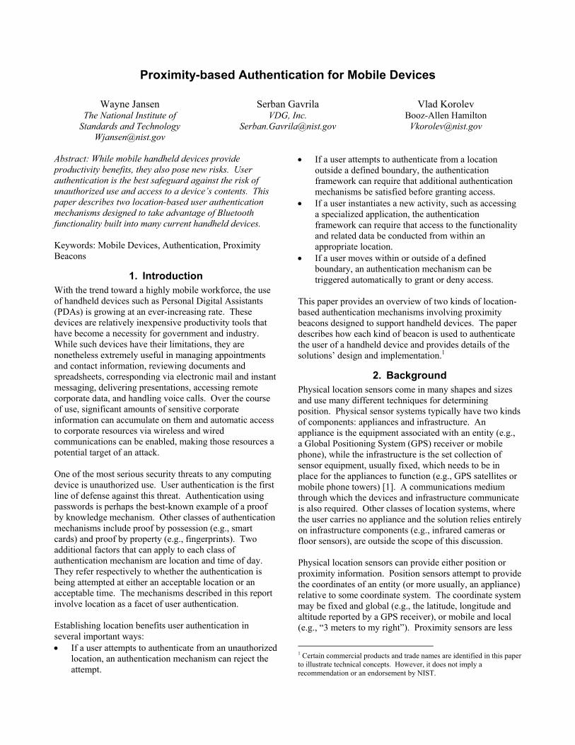
Bluetooth is a short-range wireless communications protocol for mobile devices, such as PDAs, cell phones, and headsets, that uses the globally available 2.4GHz frequency band. Many models of mobile devices are manufactured with built-in Bluetooth radios, which provide for short-range communications and have low power consumption. Two PDAs with built-in Bluetooth radios were used for the prototype implementation: one for the beacon and the other for the mobile device. The PDA simulating the personal beacon token displays a fully functional virtual token via its touch screen, as shown in Figure 1.
Figure 1: Simulated Personal Beacon
The virtual token pictured represents a key fob form factor, containing two LEDs and an on/off switch. Turning the switch on causes the beacon to start listening for connections and the LED at left to change color. The LED at right blinks when an authentication exchange occurs. The actual token could have formats other than a key fob or be incorporated into another device, such as a cell phone. Its code executes as an OPIE application.
3.1 Operation The personal beacon mechanism was designed for use with organizational handheld devices. Therefore, the design incorporates a public key infrastructure (PKI) and the use of X.509 certificates. It is also easily amenable to work solely with public key pairs generated on the token, if a PKI is unavailable for this application. In the operation of the personal beacon, three phases are distinguished: • The beacon setup phase – During this phase, the
administrator generates a pair of RSA keys, obtains a user certificate for the beacon, and stores the certificate and the private key on the beacon. The administrator also stores the root certificate (chain) of the CA that issued the beacon certificate onto the client PDA. For Bluetooth personal beacons, the PDA and personal beacon are paired to establish a long-term trusted association between the two. A special
class identifier distinguishes beacons from other Bluetooth devices and simplifies the pairing operation.
• The beacon enrollment phase – During this phase, the mechanism on the PDA tries to enroll the beacon for the first time. It consists of the following steps: • The PDA tries to identify and connect to a
personal beacon. For the Bluetooth variant, the beacon’s identity and address is already known and used to connect to the beacon directly. If no such device is found or if no connection can be successfully made, the enrollment phase fails.
• The PDA starts the high-level protocol with the connected device, by which it requests and receives the user certificate. If the certificate transfer fails, or the certificate does not verify, the enrollment phase fails.
• The PDA tries to authenticate the token through a challenge-response protocol based on the certificate information. If the authentication fails, the enrollment phase fails; if it succeeds, enrollment is complete. The PDA saves the certificate to the file system for subsequent use by the challenge-response algorithm, as a flag attesting that enrollment completed successfully, and closes the connection.
• The verification phase – During this phase, the PDA periodically initiates a challenge-response exchange with the beacon and checks that its certificate remains in effect. The authentication succeeds if the response verification is successful. This phase takes place repeatedly to ensure that the beacon is present and properly enabled.
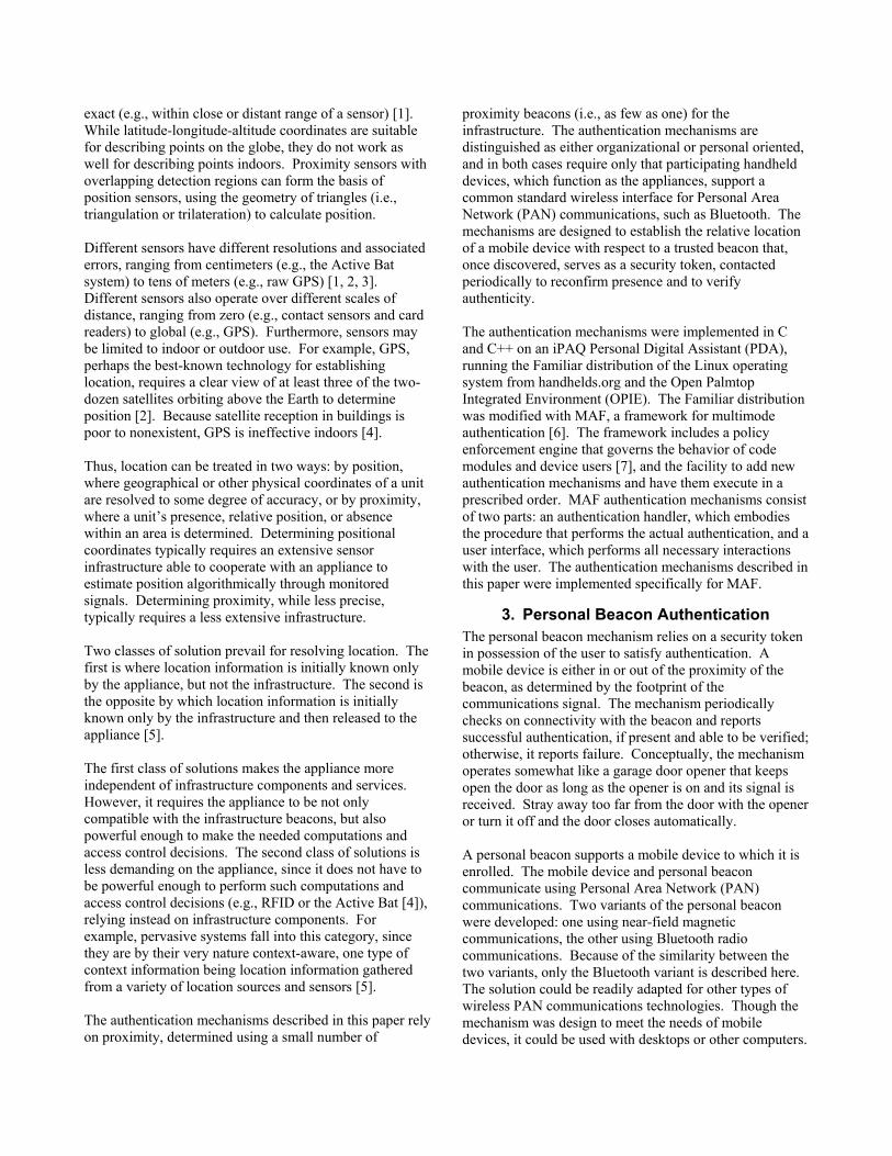
The challenge-response protocol used to authenticate users via a personal beacon is compliant with FIPS 196. Figure 2 illustrates the scheme. The upper part of the diagram shows the enrollment information exchange used to register a token (at right) with the PDA (at left), while the remainder shows the exchanges used to verify the claimed identity. For verification, the device and the token adhere to the following procedures for composing challenges and responses, outlined in FIPS 196 [8]: • The device generates a random challenge "B" and
passes it to the token for signing with the private key associated with the enrolled identity certificate.
• The token generates a random value "A", signs A||B with its private key (‘||’ denotes concatenation), and returns A and the signature to the PDA.
• The device retrieves the enrolled identity certificate, verifies it, then verifies the token’s signature over A||B using the public key in the certificate.
• If successfully verified, authentication succeeds; otherwise, the authentication attempt fails.
Figure 2: Challenge-Response Protocol
3.2 Implementation The authentication handler operates as a polling mechanism, periodically checking the status of the personal beacon token and initiating authentication with it over an L2CAP connection to the paired Bluetooth address. If the token is not yet enrolled, the handler immediately tries to register it. The handler maintains two state variables: the current authentication status and the previous authentication status. Both start out as “unauthenticated.” During a polling period, the handler first updates the previous authentication status variable with the value of the current status, then initiates the authentication exchange with the token to determine an updated value for the current status variable. A difference between the two values indicates a change of state from the previous poll and determines whether the mechanism should report a change from “authenticated” to “unauthenticated” or the reverse. One complication in deciding whether to report a change from “authenticated” to “unauthenticated” is that the mechanism must take into account the possibility of intermittent data loss, and allow a window for additional authentication attempts to succeed before rendering the decision. The software on the personal beacon token operates as a server to the authentication handler client on the PDA. The Personal Beacon starts up by initializing the OpenSSL library (www.openssl.org) and reading the user PKI credentials from files in PEM format. Next, the Personal Beacon builds and displays its interface according to the beacon’s initial state (“off,” with both LEDs unlit and the on/off switch displaying “On”). When the user clicks on the switch, the personal beacon creates an L2CAP server socket, enters the “on” state (unconnected), and starts
listening for a connection from the paired device. When it detects a connection request, the beacon accepts the connection and creates a client socket. The beacon then repeatedly polls the client socket for input requests from the device, and the server socket for new connections. The beacon processes the input received on the client socket with priority. If a new connection request arrives on the server socket, the old connection is closed and a new one is established. Input on the client socket is interpreted as a request from the client PDA. The server processes the request and returns the answer on the client socket. The high level protocol between the client PDA and the personal beacon comprises the following commands: • getCertLength – The command requests the length of
the user’s certificate in bytes. The server returns the certificate length as a decimal value.
• getCertData|offset|length – The command asks for a chunk of the certificate, starting at a specific offset and a size of length bytes. The offset and length are expressed in decimal. The server returns a string of length bytes.
• signChallenge|challenge – The command asks the server to sign a challenge, which is a string (called B) of 16 bytes randomly generated and translated by the client into a 32-byte character string. The server returns the response to the challenge, containing a random string represented as a 32-byte character string and the 256-byte representation of the signature.
• bye – The command requests the server to disconnect from the remote device by closing the client socket, resulting in the beacon state maintained at the client to become “on unconnected.” The server returns the string BYE and closes the connection with the client.
3.3 Safeguards The fundamental threat to user authentication is an attacker impersonating a user and gaining control of the device and its contents. The personal beacon token must be designed to resist physical tampering and avoid disclosing its base secret, the private key used to sign challenges it receives. The private key should be used exclusively for authentication. Since the PDA and token devices can be paired, a trusted connection exists between them during operation. Each device automatically accepts communication from the other in encrypted form, bypassing the discovery and authentication process that normally occurs during Bluetooth interactions. In addition, the challenge-response mechanism specified in FIPS 196 is designed with measures to conceal the base secret used and avoid replay. In signing the challenge and verifying the signature, the
handler and the token use OpenSSL v0.9.7 APIs that comply with the PKCS #1 standard. Other security measures applied to the device rely on MAF, which depends in turn on the security of the underlying operating system. The personal beacon handler is protected from substitution and overwrite through the multimode authentication and policy enforcement functionalities of MAF. The personal beacon handler uses the following security-related files stored on the PDA, which are also protected through policy enforcement functionality of MAF: • The X.509 certificate of the root CA used to validate
the user’s certificate on the token – installed through security administration.
• The user’s X.509 certificate – written at token enrollment, and afterwards read only by the handler.
• The token’s Bluetooth address – created during device pairing for exclusive use by the handler.
• The Bluetooth link keys – created during device pairing for exclusive use by the handler.
4. Organizational Beacon Authentication The organizational beacon is a small device placed in an area to establish a perimeter where a distinct policy is in effect. To accomplish this, the organizational beacon offers an area location service for discovery and use by mobile devices, such as PDAs. One or more organizational beacons define the area. Location is determined relative to a beacon. Mobile devices equipped with an organizational beacon authentication mechanism sense the locale of the organizational beacons and adjust their security policies accordingly. A device is either in or out of the vicinity of the beacons, as determined by the footprint of their communications signal. The organizational beacon authentication mechanism checks periodically for proximity to a beacon and reports successful authentication if a beacon is detected and able to be verified; otherwise, it reports failure. Multiple organizational beacons can be used to improve service above that of a single beacon, or arranged to service a larger area. An organizational beacon provides credential information for a device to verify using the Transport Layer Security (TLS) protocol over Bluetooth. Many mobile devices are manufactured with built-in Bluetooth radios, which allow short-range communication and have low power consumption. The solution could also be adapted for other types of wireless PAN communications technologies. Intrinsyc CerfCubes (www.intrinsyc.com) serve as the platform for the prototype organizational beacons. The CerfCube 255 includes a PXA255 microprocessor, 32MB Flash ROM, and 64MB SDRAM, in a 3” x 3” x 3” form
factor. It comes loaded with a Linux kernel and the Familiar Distribution, including device drivers for all on-board peripherals. Peripheral support includes Ethernet and several serial ports. CerfCubes come equipped with a Compact Flash slot that supports Type I and II cards, which can be used to add Bluetooth or other wireless communications, memory, etc.
4.1 Operation The organizational beacon authentication mechanism operates in two distinct modes: unauthenticated and authenticated. In unauthenticated mode, the following steps occur: • The mobile device periodically scans for the available
organizational beacons in the area. • When the mobile device finds a potential beacon, it
establishes a Bluetooth connection to it, and then attempts to set up a secure TLS connection over that physical channel, using the X.509 certificate supplied by the beacon.
• If the beacon is successfully authenticated and the TLS connection established, the mobile device enters a readiness exchange with the beacon to verify that it is indeed a functional organizational beacon.
• Once the mobile device determines that organizational beacon is functional, the device enables the associated policy for that location and switches to authenticated mode.
• Otherwise, the mobile device blacklists the beacon for a period of time and retries the above steps.
Once in authenticated mode, the following steps occur: • The mobile device periodically tries to reestablish a
TLS connection over Bluetooth with the last beacon it previously used.
• If the beacon is again successfully authenticated and the TLS connection established, the mobile device verifies that the beacon is still functional.
• Once the mobile device determines that the beacon is functional, the device maintains the associated policy for that location and remains in authenticated mode.
• Otherwise, the mobile device retries the above steps, allowing for a momentary out of range condition.
• If the beacon cannot be authenticated and vetted within a preset time, the mobile device switches to unauthenticated mode and changes policy accordingly.
The beacon itself operates as a server to the mobile device clients, listening to the inquiries and responding as needed. The Bluetooth device class identifier on the beacon is set to a specific value defined for beacon class devices. Using a customized device class improves performance, since the mobile device can filter out other types of devices that may be present in an area (e.g., cell phones, printers, etc.) and avoid interaction.
The beacon proves its identity to mobile devices, but does not require mobile devices to do the same. The beacon establishes its identity via TLS using its private key and associated certificate. The beacon’s server certificate must be valid and be issued by the organization’s root certificate authority (or by a certificate authority having a valid certificate chain from the organization’s root certificate authority). The mobile device must hold the public key of the organization’s certificate authority to verify the authenticity of the beacon server certificate. Beacons support specific policies, denoted by an identifier in their credentials. Assorted beacons may be configured to support distinct policies for different areas. Because a mobile device running the organizational beacon authentication mechanism is configured to observe a specific policy in the presence of an associated beacon, it disregards beacons that identify other policies.
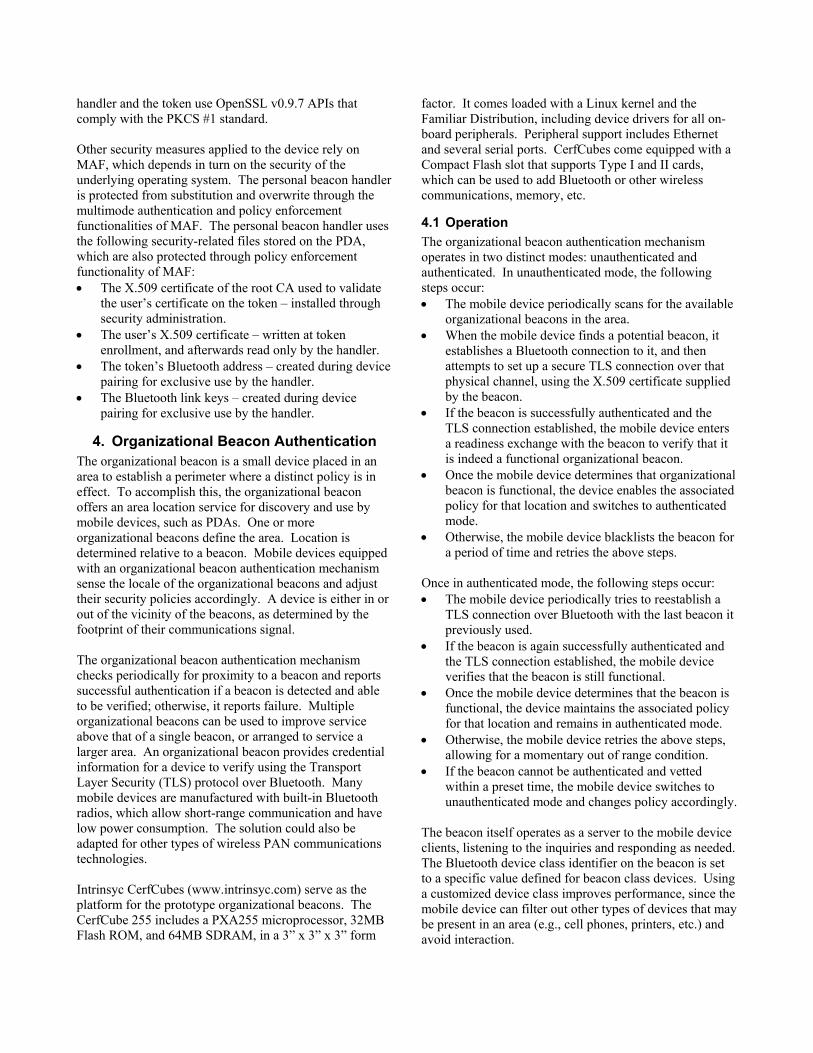
4.2 Implementation The organizational beacon handler is a polling mechanism, periodically awakening to perform the necessary operations. In unauthenticated mode, the handler periodically performs a Bluetooth inquiry to find potential beacons. If inquiry process results in finding a Bluetooth device with the beacon class identifier, the handler attempts to establish L2CAP connection to the predetermined Protocol Service Multiplex (PSM) (i.e., a designator similar to a TCP/IP port number). When the L2CAP connection is established, the handler tries to set up a TLS session over the connection and verify the server’s X.509 certificate. If the verification succeeds, the handler switches to authenticated mode, where it periodically tries to establish a connection with the last known beacon and authenticate it using the same steps as above. If the handler eventually is unable to communicate and verify the last known beacon during the allotted interval, it switches back to unauthenticated mode. The handler maintains a table of potential beacons to carry out its function. The table contains information about all Bluetooth devices in the vicinity of the mobile device. The table has the following fields: MAC Address, Last Seen, Last Contact and Status, as shown in Table 1.
Table 1: Potential Beacon Table
MAC Address Last Seen
Last Contact Status
00:02:92:21:AB:C8 20 20 Beacon 00:22:11:22:33:11 30 30 Not Beacon 00:22:99:11:11:11 20 20 Unknown
The MAC Address field contains the address of the Bluetooth device, while the fields Last Seen and Last Contact contain the time value of when the device was last
seen and when the last successful communication with the device took place. The Status field contains the handler’s idea of the device’s purpose. The Status field can be one of the following: ‘Beacon,’ ‘Not Beacon’ and ‘Unknown.’ When the remote Bluetooth device is initially entered into the table, it is assigned the ‘Unknown’ status. Later, when a successful exchange with the remote device takes place, the device is assigned the ‘Beacon’ status. If the handler can establish a connection to the remote device, but the device does not follow the readiness protocol, the device is assigned the ‘Not Beacon’ status. The handler populates the table by performing a Bluetooth inquiry process every 50 seconds. The inquiry discovers Bluetooth devices in the vicinity and returns a list of their MAC addresses. The handler looks up each MAC address received during the inquiry process to see if it already exists in the beacon table. If the address does not exist, it is entered into the table. For every MAC address received during the inquiry process, the handler updates the corresponding Last Seen entry in the handler table. When the handler is not doing an inquiry, it tries to contact the devices in the beacon table whose Status entry contains either ‘Beacon’ or ‘Unknown.’ The devices with ‘Beacon’ status are contacted before the devices with ‘Unknown’ status. During the contact, the handler first tries to establish the L2CAP connection to the remote device. The Last Contact value is updated before every attempt to establish an L2CAP connection is made. If the connection succeeds, the handler performs a TLS exchange. If a failure occurs after the L2CAP connection has been established, the handler sets the Status field of that beacon to ‘Not Beacon,’ which temporarily blacklists the beacon. If the TLS exchange results in successful authentication the handler sets the Status to ‘Beacon,’ sets the lastAuthentication variable it maintains to the current time, and does not try to contact the other devices in the table. The lastAuthentication variable is used to determine whether the current authentication is still valid. If the time value stored in this variable is less then 120 seconds before the current time, the handler considers the state to be unchanged, remaining valid. When the kernel sends an authentication request to the handler, the handler checks the current time and the value of the lastAuthentication variable and returns a positive response, if the value is within 120 seconds of the current time, or otherwise responds with negative authentication. The handler periodically sweeps the beacon table for stale entries. If the handler sees an entry with the Last Seen value older than 60 seconds, the entry is removed from the table. The handler uses the Last Contact column in conjunction with the Status column to prevent permanent blacklisting of beacons that did not correctly follow the
beacon readiness protocol previously. For example, it could be the case that the beacon was just booting up and not all the software was fully operational and able to complete the exchange. When the Status column for a particular entry contains a ‘Not Beacon’ value and the Last Contact time value is older than 20 seconds, the handler changes the Status value to ‘Unknown.’ The beacon itself is less complicated. The beacon software is a basic server that listens to incoming L2CAP connections. Once a connection occurs, it establishes a TLS protocol connection and observes its part of the readiness protocol, which involves a three-way handshake. The beacon can accept only one connection at the time. However, since the TLS exchange takes significantly less time than the Bluetooth connection time out, at least two devices can easily connect during that period. The Bluetooth stack on the beacon is configured to respond to incoming inquires and connections, known respectively as inquiry scan and page scan modes. Both the mobile device and organizational beacon manage the Bluetooth specific aspects of the communication, such as establishing and tearing down connections, determining the Message Transmission Unit (MTU) size, etc., as well as actual data transmission. Both also use the OpenSSL library to provide the TLS protocol functionality.
4.3 Safeguards The authentication mechanism requires that beacon is kept both physically and logically secure and situated at the correct location it identifies. When the authentication mechanism receives a message from a beacon, it must ensure that the message was created recently for the particular purpose intended and by the beacon claiming to have sent it. The mechanism must be able to detect when a message has been modified or forged by an attacker with access to the wireless network, or when a message issued previously (or for a different purpose) is being replayed on the network by an attacker. For these reasons, the organizational beacon handler uses the TLS protocol to authenticate potential beacons. The TLS is a well-established and carefully scrutinized protocol for secure transactions. The TLS protocol provides the assurance that the beacon is genuine. The security of the TLS protocol is based on a challenge response mechanism and public key cryptography. As with the personal beacon, the OpenSSL library (version v0.9.7) is used for cryptographic functions and the TLS implementation. Besides the TLS protocol, the authentication mechanism relies on MAF for its protection. The substitution or overwrite of the authentication handler program is prevented by MAF functionality and the underlying
operating system. The policy enforcement functionality of MAF is used also to protect the following security-related files and to grant the handler exclusive access: • The X.509 certificate of the root CA used to validate
the server’s certificate – installed through security administration.
• The policy identifier observed by the authentication handler – installed through security administration.
Blocking access to the CA’s public key certificate and the governing policy identifier prevents an attacker from substituting them with ones from a different organization to gain unauthorized access to the mobile device.
5. Conclusions While mobile devices provide productivity benefits, they also pose new risks. This paper demonstrates how proximity-based authentication can be implemented to reduce them. The approach provides users the flexibility to perform their tasks within the bounds set by an organization, and requires only a simple infrastructure.
References [1] J. Indulska, P. Sutton, “Location management in
Pervasive Systems,” Workshop on Wearable, Invisible, Context-Aware, Ambient, Pervasive and Ubiquitous Computing, February 2003, Adelaide, Australia. In Conferences in Research and Practice in Information Technology series, Vol. 21, pp.143-152.
[2] J. Hightower, G. Borriello, Location Systems for Ubiquitous Computing, IEEE Computer, 34, 8, August 2001.
[3] M. Hazas, H.Scott, J. Krumm, Location-Aware Computing Comes of Age, IEEE Computer, 37, 2, February 2004.
[4] A. Ward, A. Jones, A. Hopper, A New Location Technique for the Active Office, IEEE Personal Communications, Vol. 4 (5), October 1997, pp 42-47.
[5] M. Gruteser, G. Schelle, A. Jain, R. Han, D. Grunwald, Privacy-Aware Location Sensor Networks, USENIX 9th Workshop on Hot Topics in Operating Systems (HOTOS IX), May 2003, pp. 163-167.
[6] W. Jansen, V. Korolev, S. Gavrila, T. Heute, C. Séveillac, A Framework for Multimode Authentication: Overview and Implementation Guide, NISTIR 7046, August 2003.
[7] W. Jansen, T. Karygiannis, M. Iorga, S. Gavrila, V. Korolev, Security Policy Management for Handheld Devices, The 2003 International Conference on Security and Management (SAM'03), June 2003.
[8] Entity Authentication Using Public Key Cryptography, Federal Information Processing Standards Publication (FIPS PUB) 196, U.S. Department of Commerce, National Institute of Standards and Technology, February 1997.