proytec system manual
TRANSCRIPT

1
PROYTEC SYSTEM MANUAL 1 Theory of Corrosion p. 2
2 Sacrificial Anodes p. 2
3 Cathodic Protection through impressed current p. 2
4 Proytec equipment, concepts and operation p. 3
5 Control equipment p. 4
6 Proytec system advantages p. 5
7 Proytec equipment p. 5
7.1 Titanium anode and regulator p. 5
7.2 Reference electrode and control system p. 6
7.3 System for grounding propeller shaft p. 6
7.4 Titanium potential filter p. 6
8 Proytec system elements p. 7
8.1 Anode p. 7
8.2 Regulator p. 7
8.3 Grounding plate (union point) p. 7
8.4 Reference electrode p. 8
8.5 Control panel p. 8
8.6 System for grounding propeller shaft p. 8
8.7 Titanium potential filter p. 8
9 Installations instructions p. 9
9.1 Anode p. 9
9.2 Regulator p. 14
9.3 Grounding plate (union point) in egine room p. 16
9.4 Grounding plate (union point) boat’s bridge p. 18
9.5 Reference electrode p. 21
9.6 Control panel p. 24
9.7 System for grounding propeller shaft p. 28
9.8 Titanium potential filter p. 30
2
1 Theory of Corrosion
Corrosion is the phenomenon through which metallic elements lose electrons from the outer layers of
their atomic structure to combine with oxygen and form oxides. Metallic elements have a
predisposition to lose electrons when in contact with water. Each type of metal has a particular
electrical charge and a specific tendency for loss. These varying characteristics of corrosion
resistance (in water) can be compared. Prevention of galvanic corrosion consists of using metals that
tend to lose large amounts of electrons in order to prevent the loss of electrons from other metals
(stops degradation of the metal to be protected). Using this principle, we sacrifice the metal in order
to protect other metals of greater importance and in effect leave the protected metals unaltered.
2 Sacrificial Anodes
This is the name that we give to zinc anodes, aluminum or any highly negatively-charged metals
present below the waterline of any vessel whose only purpose is to protect against attack from water.
Propellers, shafts, rudders, keels as well as the entire hull should be protected against corrosion in
order to have optimum performance. Traditionally zinc anodes have been used for this protection.
The enormous capacity of zinc anodes to lose electrons in water is what allows them to prevent the
same loss of electrons in other metals on the hull and to protect those metals. The anodes degrade
(dissolve/decompose) progressively over time and release the zinc into the surrounding waters.
3 Cathodic protection through impressed current
When in a normal state, Iron has a negative potential of approximately -600mV. When in contact with
water Iron has a tendency to transfer electrons in water and oxidize. Studies about Iron and water
have concluded that beyond -800mV transfer of electrons is detained as well as degradation of the
metal. The practical application of these investigations, raising the negative potential of the metal to
be protected in order to stop corrosion, was perfected through impressed current technologies.
Maintaining a negative potential of the metals to be protected is analogous to using traditional anodes
with the exception that in this case sacrificial metal anodes are not necessary.
The concept of Cathodic protection through impressed current is routinely used in large ships (super-
tankers, cargo ships, etc.). The simplification and miniaturization of these concepts into electronic
components has permitted the development of a system for smaller vessels with hulls made of
fiberglass, iron or aluminum.
3
The Proytec system, based on the principles mentioned above, incorporates compact electronic
components that require only a minimum of upkeep. The system attains efficient protection for all
metals below the waterline of the vessel by producing the necessary negative potential for any given
situation.
4 Proytec equipment, concepts and operations
As discussed earlier, it is necessary to create a potential between the parts to be protected and the
sea water. This is achieved through use of the PROYTEC system by the following process:
• The first step is to unite all elements that are to be protected (metal hull, motors, navigation
equipment, metal elements, etc.) through a cable to a copper plate measuring 250 x 50 x 5mm.
The negative pole of the boat’s battery is connected to this same plate.
• A regulator which is powered by the boat’s battery is in charge of sending the proper negative
potential to the copper plate.
• At the same time an activated titanium anode (that goes through the hull) is also connected to the
same regulator mentioned before, and is connected to the positive pole of the boat’s battery.
• This creates a potential between the sea water (positive) and the rest of the metallic elements
(negative).
The regulator consists of an electronic system which acts through the use of a potentiometer allowing
for incremental or reduction adjustments in the quantity of mili-amperes released into the water. This
current, which should achieve the necessary negative potential to protect each metal part (ex. Iron -
800 mV), is proportional to the area to be protected. The potentiometer, whose tension is manually
adjustable, releases more or less intensity of current depending on the needs in each case.
4
Each vessel needs a different amount of mili-amperes to be properly protected depending on the
distribution, quantity and type of metals used on that vessel. As an example, an unpainted iron hulled
boat requires 100-200 mA/m². With a painted hull the value could oscillate around 15 times less.
Protection of the propeller shaft is achieved through the use of bronze calipers ,connected to the
boat’s ground, that have two metallic brushes which transmit negative current to the propeller (all are
inter-connected at the copper plate mentioned earlier).
The protected elements should achieve a determined potential. But how does one verify and adjust
the potential to pre-established values? The system includes a zinc reference electrode. By means
of a through-hull fitting the reference electrode, situated below the waterline, transmits information
about the actual potential of the hull on a continuous basis.
Based on the information sent to the regulator, the potentiometer can be adjusted to change the
amount of current delivered to the anode. The PROYTEC system allows for adjustments (whether
the vessel is docked or under navigation) in order to achieve optimal protection.
5 Control equipment
To verify the status of the hulls protection, an electronic panel light panel is used. The panel is
connected to the positive pole of the battery (in line fuse), the reference electrode and the grounding
point (elements to be protected which are united at the copper plate).
The panel consists of a microprocessor which incorporates in its memory the protection curves. The
curves are data based on the corrosion of each type of metal. The panel consists of 12 LEDs which
indicate whether the boat is protected or not. When the panel button is pushed, the LEDs light up
giving information about the status of the vessel. If a red light is visible, then corrosion exists. If there
is one green light, there is protection. If a yellow light is visible then there is over protection.
This way the status of the hull can be determined as well as the correct functioning of the equipment.
The boat’s protection can be monitored at any moment.
6 Proytec system advantages
• The Proytec system controls the status of protection of the submerged metal parts through use of
the lights panel which allows for adjustments to achieve optimal protection throughout the life of
the boat.

5
• The system eliminates sacrificial anodes (normally zinc), and their reflectivity (an issue when
fishing certain species), turbulence and negative environmental effects on wildlife.
• By eliminating the need to replace zinc anodes on a yearly basis, the Proytec equipment is
amortized in 3/5 years.
• By eliminating zinc anodes we avoid adding pollution and heavy metals into the water
environment.
PROYTEC is a Cathodic protection system that uses impressed current for vessels of the following
sizes:
7 Proytec equipment
7.1 Titanium Anodes and regulators
To achieve the necessary tension/current in the protected parts and make the water positive, we use
an activated titanium anode which does not degrade/dissolve and at the same time remains active
when sending positive current through the water.
The electronic regulator is in charge of sending the proper levels of continuous current necessary to
maintain the metal’s immunity potential (level at which metal part is protected and not corroding). The
energy management system ensures that battery use remains minimal.
6
7.2 Reference electrode and control system
The reference electrode (which is mounted in the hull) sends the potential values to the control panel.
This same signal goes to a microprocessor and through use of the 12 LEDs indicates the status of
protection. With the use of the control panel, which is mounted on the bridge/cockpit/control room it is
possible to know the exact status of protection at any moment.
7.3 System for grounding propeller shaft
The propeller and shafts need extra attention because those are areas where high levels of corrosion
exist. To ensure that negative current reaches the sensitive area, such as the propeller and shaft,
Proytec includes in each protection package, a grounding ring for the shaft and special contact
brushes to ensure proper contact with the ring.
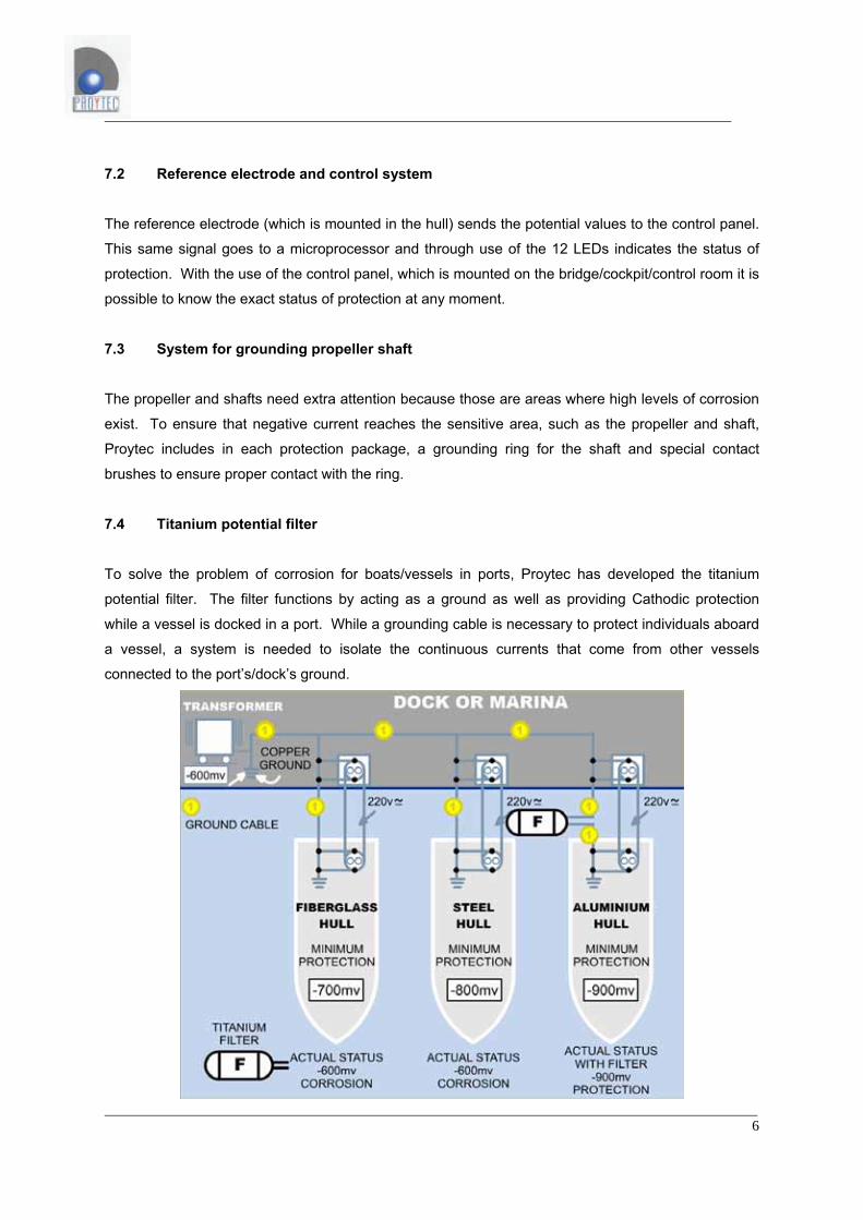
7.4 Titanium potential filter
To solve the problem of corrosion for boats/vessels in ports, Proytec has developed the titanium
potential filter. The filter functions by acting as a ground as well as providing Cathodic protection
while a vessel is docked in a port. While a grounding cable is necessary to protect individuals aboard
a vessel, a system is needed to isolate the continuous currents that come from other vessels
connected to the port’s/dock’s ground.
7
The potential filter, constructed of long lasting titanium electrodes, sits between the grounding cable
from the power source and the water where it is submerged. The boat now is grounded and at the
same time is protected against corrosion.
Because the filter does not contain electronic components, it is not vulnerable to failures, ensuring
total reliability for the safety of the people aboard the vessel. This reliability also relates to the
isolation of the vessel from other boats as well as the dock/port.
8 Proytec system elements: 1. Anode
2. Regulator
3. Union point on copper plate in engine room and on bridge/control room
4. Reference electrode
5. Control panel
6. Grounding system propeller shaft
7. Titanium potential filter
8.1 Anode
The activated titanium anode has a minimum life of 20 years. The anode is responsible for making all
the submerged metal parts of the boat negative in reference to the sea water, which receives positive
current. The regulator delivers this current which is released through the anode. There are various
sizes of anodes depending on the size of the area submerged that needs to be protected.
8.2 Regulator
The regulator is powered by the boat’s battery. There are two types: 24V and bi-tension (12-24V) and
in various potentials depending on the size of the vessel and the area of submerged metal. All
versions have various adjustment systems to ensure that the submerged parts of the boat are
protected while using the lowest amount of battery power possible.
8.3 Grounding plate (union point)
These are two copper plates that are included with the equipment to ensure that all submerged
metallic parts and any equipment that could influence the protection level do not interfere with the
corrosion control.
8
8.4 Reference electrode
From a physical aspect the exterior of the electrode is similar to an anode, however the electrode
serves a different function. The purpose of the electrode is to read the negative potential of the
submerged metallic parts of the vessel to ensure proper Cathodic protection at all times. Care must
be taken not to confuse the electrode with the anode when installing the system because severe
damage could be caused to the equipment in addition to the fact that the boat would not be protected
against corrosion. It is easy to distinguish between the electrode and the anode. The activated
titanium anode is flat black while the reference electrode is a brilliant metallic color.
8.5 Control panel
This is the equipment that visually controls the status of Cathodic protection on the vessel. It consists
of a microprocessor powered by the boat battery and receives the electric signal from the reference
electrode.
8.6 System for grounding propeller shaft
This is necessary for delivering negative current to the propeller, the shaft and all metallic support
mechanisms. It consists of a pair of contact brushes with springs that ensure constant
pressure/contact with the supplied copper shaft ring (ring fits around shaft and held together by
screws). This ring is custom made to fit the exact diameter of the vessel’s propeller shaft. For this
reason it is necessary to know the exact diameter of the shaft down to tenths of a millimeter.
8.7 Titanium potential Filter
Its job is to isolate the protection potential of the boat from the rest of the marina without reducing the
level of safety that is given when connecting to a dock’s ground when connecting to shore power.
9
9.1 Installation Instructions: Anode • The anode will be placed in a location chosen by PROYTEC and indicated in installation
documents. In certain cases PROYTEC will offer an alternative installation area for the anode if
necessary. Normally the anode is installed in a submerged safe location where there is little
chance of damage from docking or from fishing nets.
• In the case of wood or fiberglass boats, (non-metallic hull) care should be taken to avoid
installation near metallic parts (negative pole of installation) such as shaft supports, metallic
through-hull fittings, propeller shafts, etc. because the anode is positive and sea water is very
conductive. This would result in insufficient current because the current would flow to the nearest
metallic part. The anode should be at least 2 meters from these metallic parts.
• In metallic hulls a dielectric shield should be painted in the area surrounding the anode by using
two coats of thick epoxy paint in addition to the normal anti-fouling paint. This ensures that the
current from the anode is not directed to the metal in the closest proximity and instead distributes
evenly throughout the hull.
• The anode plane should be installed vertically or at a 45º maximum. In no case should the anode
be installed horizontally. Because of the release of gases (from the electrolysis of sea water), the
bubbles would be caught on top of the anode reducing the effective area and the amount of
current released into the water would be reduced.
• The anode material is metallic Titanium covered by a layer of activated material which is flat black
in color. The activated layer should not be touched, painted or high-pressure washed or with
abrasives in order to avoid damage to the anode.
• Drill a hole a little more than 1mm greater than the diameter of the thread. This will be indicated
in the installation instructions.
• The cofferdam should be installed taking into account the dimensions of the anode as indicated in
the installation plans. Proytec can supply plans for building a cofferdam if needed.
• Once the anode and the collar are in their correct position three lines of Sikaflex (type of silicon)
should be placed between the hull and the anode as indicated in the installation plan.
• A line of Sikaflex silicon should also be placed on the exterior of the anode against the hull. The
exposed silicon should be protected by two coats of a special paint provided by Proytec. These
areas should be inspected before placing the boat in the water painting them again if necessary
because the anodic gases could damage the silicon. Painting of the Sikaflex should be delayed at
least 48 otherwise the silicon might not be able to polymerize.
• After placing the locking nut in the interior of the vessel on the anode, place a good sized bead
along the threads of the anodes just above the nut.
10
• The placement of the cables needs special care. Do not bundle the system cables with other
cables when bringing them to the bridge especially with cables that are conductive and carry AC
current. These cables could cause interference and introduce currents that could damage the
regulator. The cable from the anode should be separated by at least a meter or more if possible
from AC cables. To avoid interference, don’t bundle the red cable near the blue cable of the
electrode. • The splicing of the anode cables (to lengthen), 25mm² (product models C, D, D1)(red), and
50mm² (product models D2 and D3) is done by soldering and isolating them with shrink
tubing/wrap at a level above the bilge. The splice should be as close to the anode as possible,
cutting the extra cable from the anode. This splice should be done in a zone with easy access
where inspections can be carried out periodically.
11
IMPORTANT: SEALING/GLUING ANODES AND ELECTRODES WITH SIKAFLEX: GENERAL RULES
• PREPARATION OF THE SURFACE
Although Sikaflex sticks well to polyester (Gel-Coat) and epoxy paints, the adhesive characteristics
improve when you pass a Scotch Brite green pad over the surface. After using the abrasive it is
recommended that Sika Cleaner 205 solvent be used to clean the surface area. The next step is to
apply Sika Primer 210T and let dry for 45 minutes.
NOTA: (In cases where it is necessary to glue on top of painted surfaces that are not epoxy based,
consult with your nearest Sika dealer).
• GLUING WITH SIKAFLEX
The type of Sikaflex to apply is Sikaflex 291 (black). The beads or lines to be applied should follow
the instructions for the type of anode and electrode. The working temperature for application should
not be outside the following range of [+5C - +35C].
The time necessary for the Sikaflex to form a protective skin at +20C and 65% relative humidity is 60 minutes. In the same conditions the Sikaflex polymerizes approx. 3mm per 24 hours.
The most important beads/lines of Sika application (in terms of responsibility) are the surrounding
borders of the anode and electrode, as well as on the threads and nuts and on the inside of the
vessel. Under no circumstances should application of the adhesive deviate from the instruction
manual.
12
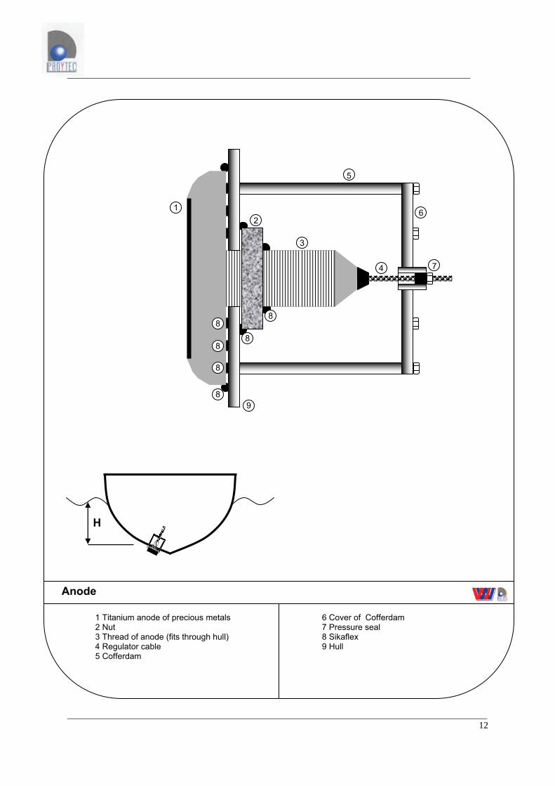
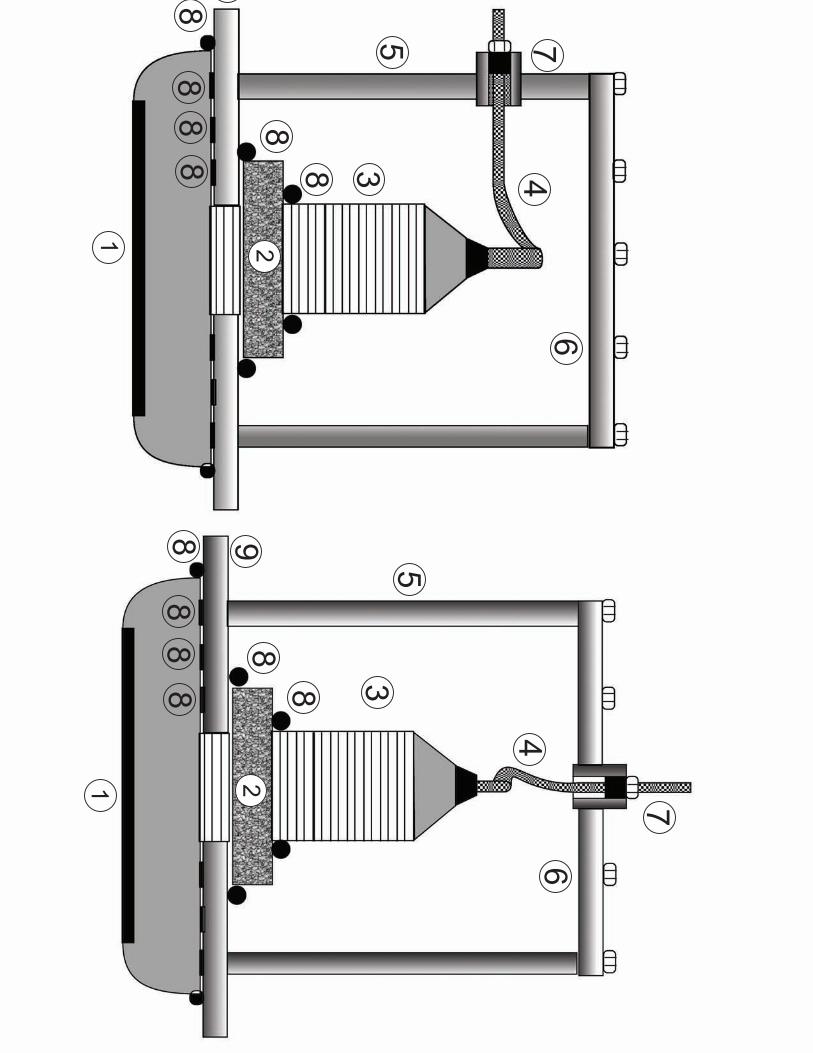
1 Titanium anode of precious metals 2 Nut 3 Thread of anode (fits through hull) 4 Regulator cable 5 Cofferdam
Anode
1 2
3
4
5
6
7
8
8
8
8
8
8
9
6 Cover of Cofferdam 7 Pressure seal 8 Sikaflex 9 Hull
H
1 2
3
4
5
67
1 2
3
4
5
6
7
88
8
88
88
88
8
88
9

13
1 Cable 2 Nut 3 Titanium
Anode
Anode Type L1 L2max L3 L4 H1 H2 H3 Ø
A
B
B1
D
D1
D2
C
14
9.2 Installations instructions: Regulator • The regulator should be installed on the bridge/control room at least 1 meter apart from the
control panel to avoid interference. INSTALL IN A HIGHLY VISIBLE LOCATION. The regulator
has two parallel cables (Red-Black); one is connected to the battery and the other to the anode
and copper union plate/bus bar.
• Each parallel cable has a connector with a hanging cable which should be installed inside the
boat. The connectors make it easier to remove the regulator by hand in case it needs to be
changed.
• The cable that goes to the battery should be attached in the following manner: The red cable is
connected to the positive (+) battery terminal as well an in line fuse; the black cable is connected
to the copper union plate/bus bar in the bridge/control room. These connections should always
remain the same.
• Do not plug in the wire connected to the battery until it has been verified with a tester/voltmeter
that positive current is being sent through the red cable. A polarity inversion (backward
connection) would damage the regulator.
• The parallel cable that exits the regulator is connected in the following manner; the red cable is
connected to the two anodes and the black cable is connected to the copper union plate/bus bar
in the bridge/control room. A connection inversion with these two cables would create a situation
of corrosion instead of protection.
• The regulator should be adjusted with two potentiometers through use of a switch. In the port
position the adjustment should be made until the first green light turns on. In the navigate position
the same procedure should be followed. The two readings from the amp meters should be
controlled every time there is a switch from port to navigate.
• Keeping the regulator cool is very important so care must be taken to install it in a vertical position
with at least 10cm clearance above and below the regulator.
• The ends of the cables are equipped with easy release fasteners (which also prevent incorrect
connections). These cables will need to be lengthened. It is advisable to seal the splices with
shrink tubing or to use high quality terminal blocks to join cables.
• In a situation where the regulator needs to be changed, all that needs to be done is release the
fasteners. The new regulator would connect to the same fasteners in the same way. Any
manipulation of these connectors will void the guarantee. Do not break the seal on the regulator
or open the case as this will also void the warrantee.
• Never turn on the equipment when the boat is out of the water because of possible static damage. • The maximum intensity that a regulator can output will depend on the equipment installed on the
boat. The owner will be notified by the distributor the type installed. This intensity level will be in
the majority of cases, less than the characteristics placed on the back label of the regulator.
Never exceed this limit without authorization from the distributor. The regulators should be
equipped with a spike filter at the entrance.
15
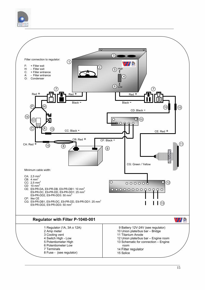
9 Battery 12V-24V (see regulator) 10 Union plate/bus bar – Bridge 11 Titanium Anode 12 Union plate/bus bar – Engine room 13 Schematic for connection – Engine room 14 Filter regulator 15 Splice
1 Regulator (1A, 3A o 12A) 2 Amp meter 3 Cooling vent 4 Switch High - Low 5 Potentiometer High 6 Potentiometer Low 7 Terminals 8 Fuse - (see regulator)
Regulator with Filter P-1040-001
A
1
2
3
4
5
6 7
8
7
9
10
11
12
13
Black -
CF: Black -
CD: Black -
Black -
CC: Black - CE: Red +
CA: Red +
Red + Red + Red +
H F
C A
Minimum cable width: CA: 2,5 mm2
CB: 4 mm2 CC: 2,5 mm2 CD 10 mm2 CE: E9-PR-DA, E9-PR-DB, E9-PR-DB1: 10 mm2 E9-PR-DC, E9-PR-DD, E9-PR-DD1: 25 mm2 E9-PR-DD2, E9-PR-DD3: 50 mm2 CF: like CE CG: E9-PR-DB1, E9-PR-DC, E9-PR-DD, E9-PR-DD1: 25 mm2 E9-PR-DD2, E9-PR-DD3: 50 mm2
1515
15
15
CG: Green / Yellow
Filter connection to regulator: F: + Filter exit H: - Filter exit C: + Filter entrance A: - Filter entrance O: Condenser
14
Low
High
O
CB: Red +
16
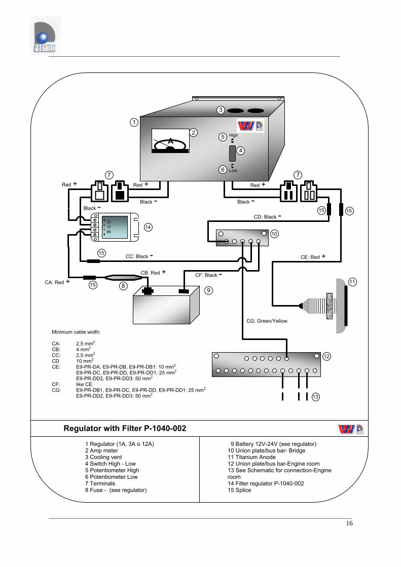
9 Battery 12V-24V (see regulator) 10 Union plate/bus bar- Bridge 11 Titanium Anode 12 Union plate/bus bar-Engine room 13 See Schematic for connection-Engine room 14 Filter regulator P-1040-002 15 Splice
1 Regulator (1A, 3A o 12A) 2 Amp meter 3 Cooling vent 4 Switch High - Low 5 Potentiometer High 6 Potentiometer Low 7 Terminals 8 Fuse - (see regulator)
Regulator with Filter P-1040-002
A
1 2
3
4
5
67
8
7
9
10
11
12
13
Black -
CF: Black -
CD: Black -Black -
CC: Black - CE: Red +
CA: Red +
Red + Red +Red +
Minimum cable width: CA: 2,5 mm2
CB: 4 mm2 CC: 2,5 mm2 CD 10 mm2 CE: E9-PR-DA, E9-PR-DB, E9-PR-DB1: 10 mm2 E9-PR-DC, E9-PR-DD, E9-PR-DD1: 25 mm2 E9-PR-DD2, E9-PR-DD3: 50 mm2 CF: like CE CG: E9-PR-DB1, E9-PR-DC, E9-PR-DD, E9-PR-DD1: 25 mm2
E9-PR-DD2, E9-PR-DD3: 50 mm2
1515
15
15
CG: Green/Yellow
Low
High
CB: Red +
IN
OU
Black - 14
(-)
(+)
(+)
(-)
(+)
(+)
(-)
+
+
--
out
in(-)
(+) (-) (-)
F.1
1
5 6
14
10
1211
9
F.2
CE
CB
CF
CG
S.R
B- B1- C- D- D1
CC
2

(-)
(+)
(+)
(-)
(+)
(+)
(-)
+
+
--
out
in(-)
(+) (-) (-)
F.1
1
5 6
14
10
1211
9
F.2
CE
CB
CF
CG
S.R
D2
CC
2
(-)
(+)
(-)
(+)
(+)
(-)
(+)
(-)+
+
--
+
+
--
(+)
(-)
(-)
(-)(+) (-)
(+)
(-)
(+) (+)
S.R.
(-)
(+)
1 1
5 6 5 6
CECE
F.2 F.2
F.1
1414
1111LCC
10
LCA
912
CGCF
D3
22
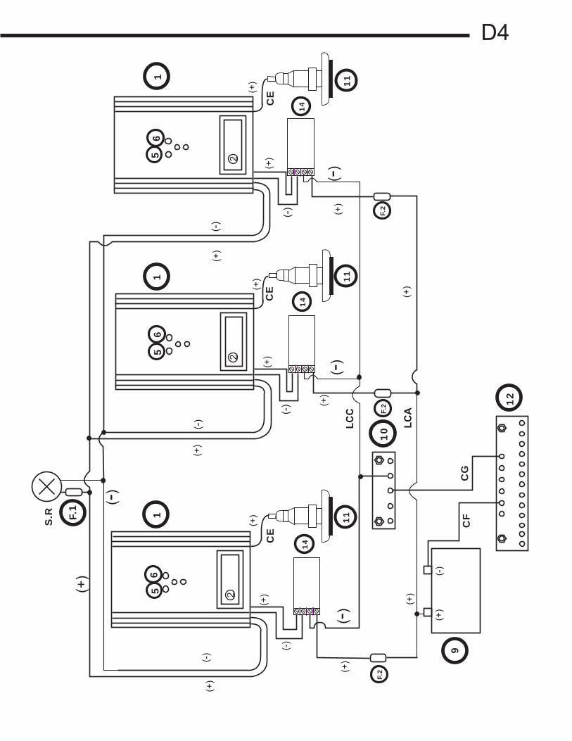
D4
22
2
(+)
(-)
S.R F.
1
11
1
12
9
(+)
(-)
F.2
F.2
F.2
11
11
11
(-)
(+)
(+)
(-)
(+)
(+)
(+)
(+)
(+)
(+)
(+)
(+)
(+)
(+)
(+)
(+)
(-)
(-)(-)
(-)
(-)
(-)
(-)
CF
CE
CE
CE
CG
LCC
LCA
55
56
66
14
14
14
10
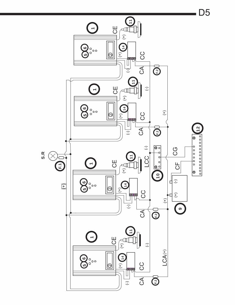
D5
22
22
S.R
F.1
1
11
11
11
11
12
9
11
1
F.2
F.2
F.2
F.2
(+)
(+)
(+)
(+)
(+)
(+)
(+)
(+)
(+)
(+)
(+)
(+)
(-)
(-)
(-)
(-)
(-)
(-)
(-)
(-)
(+)
LCA
CG
CC
CF
CC
CE
CE
CE
CE
56
56
56
56
14
14
14
10
14
CA
CC
CA
CA
CA
CC
LCC
PROTECCION CATODICA (C.I.) DE PEQUEÑAS EMBARCACIONES S.L. E-Mail: [email protected] - WEB: www.proytec.com
C/ Ecuador 10,Bajo 18 28220 Majadahonda - Madrid
Tel :+34-91-6385512 Fax: +34-91-6385578
N.I.F: B-82365297
Modificado el 05/08/2008 1/1
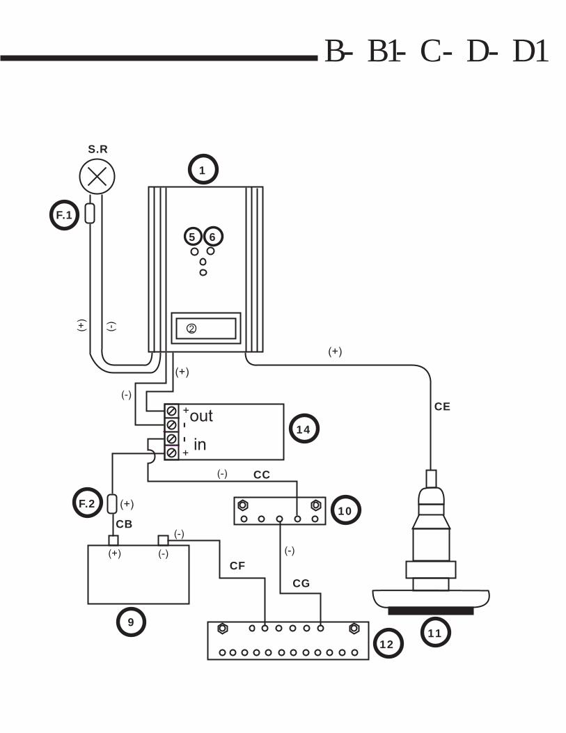
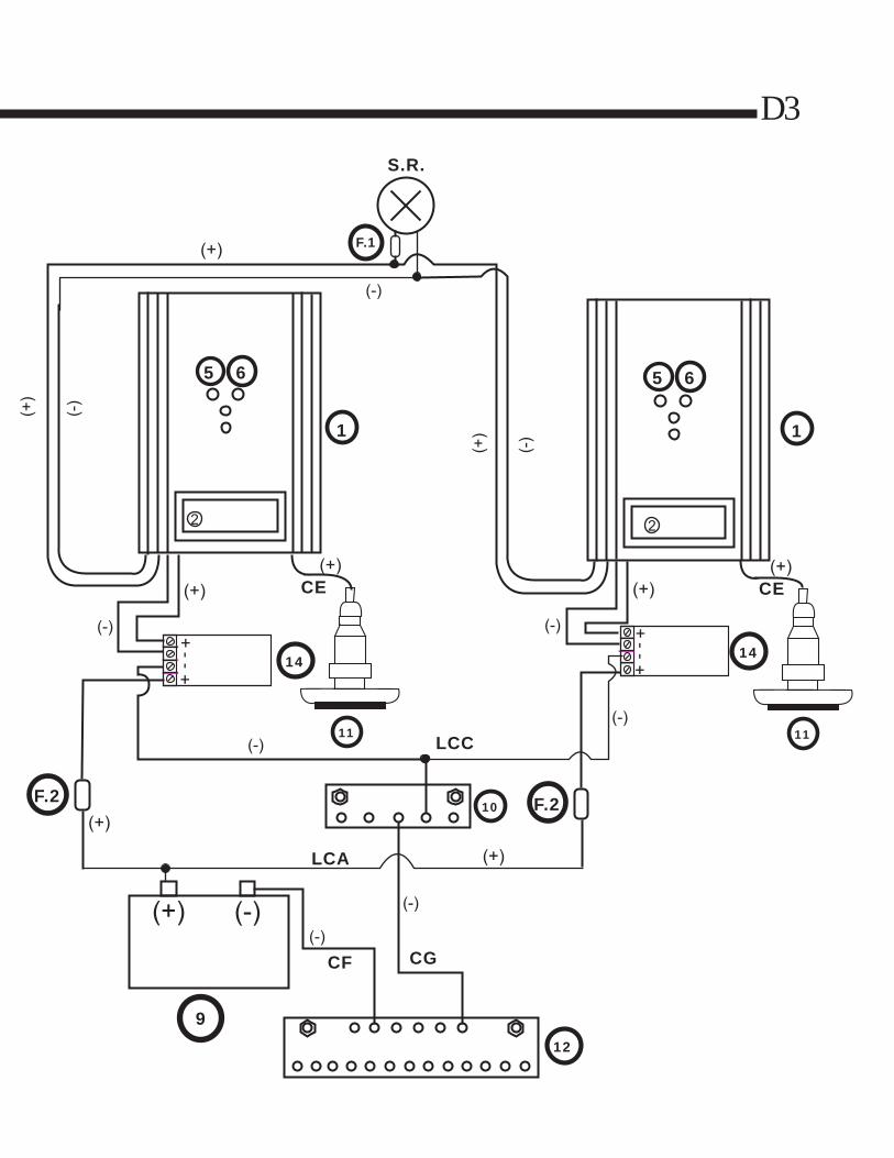
Components of Protection Equipment 1………………………………………………REGULATOR 2 ……………………………………………AMP METER 5 Y 6……POTENCIAL METER ADJUSTMENTS HIGH AND LOW S.R….PRINCIPAL MOTOR IN USE SIGNAL, WHICH ACTIVATES AN INTERNAL RELAY IN THE REGULATOR SO THAT THE HIGH POTENCIAL METER ADJUSTMENT IS ACTIVATED F1……………………..…POWER SOURCE FUSE RELAY 1 A. F2………………REGULATOR POWER SOURCE FUSE (SEE REGULATOR AMP INDICATOR LABEL) 9……………………. BATTERY 10…………………GROUNDING PLATE BRIDGE 11…………………………..TITANIUM ANODE 12………………………ENGINE ROOM GROUNDING PLATE 14……………………………………SPIKE FILTER

PROTECCION CATODICA (C.I.) DE PEQUEÑAS EMBARCACIONES S.L. E-Mail: [email protected] - WEB: www.proytec.com
C/ Ecuador 10,Bajo 18 28220 Majadahonda - Madrid
Tel :+34-91-6385512 Fax: +34-91-6385578
N.I.F: B-82365297
Modificado el 05/08/2008 1/1
MINIMUM CABLE SECTIONS MODELS: B,B1,C,D Y D1 MODELS CABLES MINIMUM SECTION MM2 B Y B1 CB 1,5mm2 B Y B1 FROM(14) TO (1) maximum length 4m. 1,5 mm2 B Y B1 CC 1,5mm2 B Y B1 CF 4 mm2 B Y B1 CG 4mm2 B Y B1 CE 4mm2 B Y B1 From (S.R) to (1) max length 10m. 1mm2 C Y D CB 2,5mm2 C Y D From (14) to (1) max. Length 4m. 2,5mm2 C Y D CC 2,5 mm2 C Y D CF 10mm2 C Y D CG 6mm2 C Y D CE 10mm2 C Y D From (S.R) to (1) maximum length 10m. 1mm2 D1 CB 4mm2 D1 From(14) to (1) maximum length 4m. 4mm2 D1 CC 4mm2 D1 CF 25mm2 D1 CG 10mm2 D1 CE 25mm2 D1 From (S.R) to (1) maximum length 10m. 1mm2
PROTECCION CATODICA (C.I.) DE PEQUEÑAS EMBARCACIONES S.L. E-Mail: [email protected] - WEB: www.proytec.com
C/ Ecuador 10,Bajo 18 28220 Majadahonda - Madrid
Tel :+34-91-6385512 Fax: +34-91-6385578
N.I.F: B-82365297
Modificado el 05/08/2008 1/1
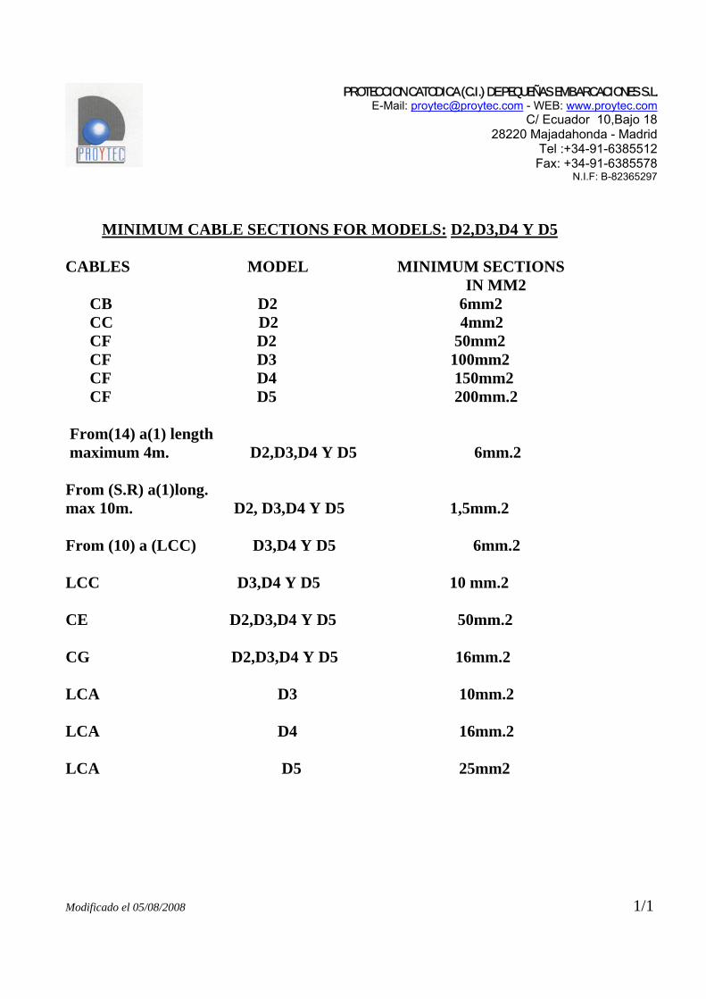
MINIMUM CABLE SECTIONS FOR MODELS: D2,D3,D4 Y D5 CABLES MODEL MINIMUM SECTIONS IN MM2 CB D2 6mm2 CC D2 4mm2 CF D2 50mm2 CF D3 100mm2 CF D4 150mm2 CF D5 200mm.2 From(14) a(1) length maximum 4m. D2,D3,D4 Y D5 6mm.2 From (S.R) a(1)long. max 10m. D2, D3,D4 Y D5 1,5mm.2 From (10) a (LCC) D3,D4 Y D5 6mm.2 LCC D3,D4 Y D5 10 mm.2 CE D2,D3,D4 Y D5 50mm.2 CG D2,D3,D4 Y D5 16mm.2 LCA D3 10mm.2 LCA D4 16mm.2 LCA D5 25mm2

17
9.3 Installation instructions: Grounding plate (union point) in engine room
1. Rudder – Port (16) 11. Motor – Starboard (25)
2. Rudder – Starboard (16) 12. Battery A (25)
3. Propeller – Port (16) 13. Battery B (in case of 2 batteries) (25)
4. Propeller – Starboard (16) 14. Keel (25)
5.
Shaft – through-hull fitting – Port (10) –
(25)* 15. Free
6.
Shaft – through-hull fitting – Starboard
(10) – (25)* 16. Free
7. Through-hull fittings (6) 17. Free
8. Through-hull fittings (6) 18. Free
9. Metals (25) 19.
To the copper union plate/bus bar on Bridge (25 with Products C, D and D1 and 50 in products D2 and D3
10. Motor – Port (25)
(In parenthesis: minimum width or section of copper in mm²)
• The copper union plate/bus bar of the engine room should be kept in a visible/accessible location
and kept totally clean (no oxidation).
• All the above mentioned elements should be connected to the copper union plate/bar bus.
• (*): Note about the connections: 5 and 6 in fiberglass and wood boats with metal keels. The
current reaches the keel by means of the shaft through-hull fitting because the cable of the shaft
through hull fitting should have a width of 25mm² instead of 10mm². In addition, two metal strips
approx. 200 x 30 x 5mm connect to the keel and the shaft through-hull fitting ensuring proper
current transfer. One strip is placed on the Port side and another on the Starboard side.
• The terminals should be connected by means of flat head screws made of bronze or stainless
steel of the following size M – 6 Ø X 16
• A and B are fastened with stainless steel screws or nuts of M – 8 Ø to the wall
(All of the grounding cables should be green or yellow and with the minimum width/section indicated)

18
Union plate/bus in engine room
250 mm
50 mm
1 2 3 4 5 6 7 8 9 10 11 12 13
14 15 16 17 18 19 B A

19
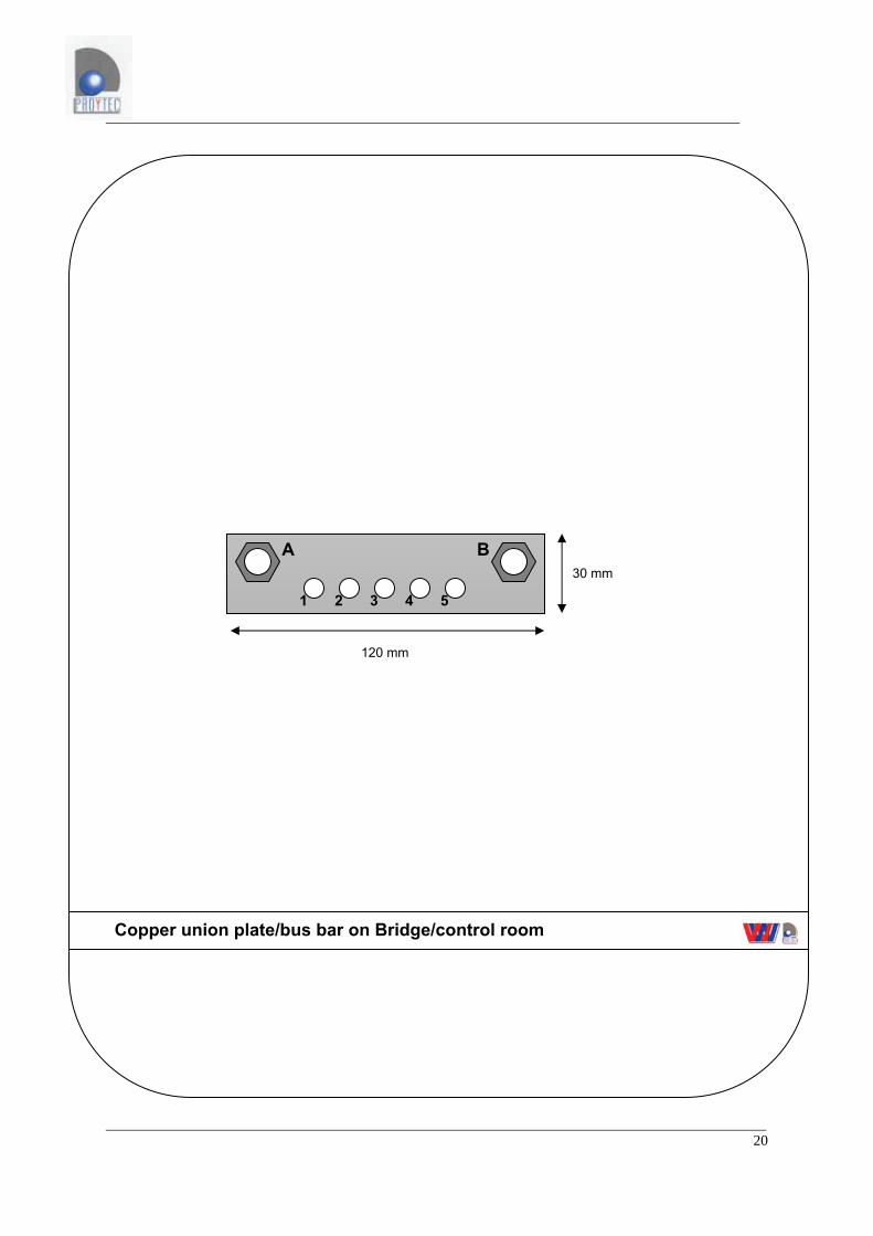
9.4 Installation instructions: Copper union plate/bus bar – Bridge/control room
1. Regulator – Negative pole (161) and black power cables: regulator
and light panel (see plans)
2. Control panel – Negative pole (16)
3. Cables to the engine room copper union plate/bus bar (25 with
product C, D and D1 and 50 with products D2 and D3)
4. To ground (only in metal hulled boats and only if there is a ground
nearby) (25)
5. Battery ( only if it is on the bridge)
(minimum section/width of copper is in mm²)
• The copper union plate/bus bar of the Bridge/control room should be situated as close as possible
to the regulator and lights panel.
• From the regulator a cable is connected to the copper union plate/bus bar on the bridge/control
room. At the same time, the plate on the bridge is connected to the engine room plate by means
of a cable with a greater section/width in order to ensure that negative tension reaches the engine
room. In this way the elements indicated in the schematic for the engine room are protected.
• The terminals are connected by means of bronze or stainless steel flat head screws of M - 6Ø X
16
• A and B are fastened with stainless steel screws or nuts M - 8Ø to the wall.
(All ground cables should be green or yellow)
20
Copper union plate/bus bar on Bridge/control room
120 mm
30 mm
1 2 3 4 5
B A
21
IMPORTANT: COPPER UNION PLATE/BUS BAR ENGINE ROOM:
There are two union plates/bus bars in all boats, one in the engine room and one on the bridge/control
room. The one in the engine room connects all metal parts that are submerged in the sea water to
the negative current that comes from the regulator in order to protect those parts (see engine room
diagram). Any submerged part that does not get connected is subject to corrosion. Only parts that
are properly connected will be protected. In addition to the protection of these parts you must connect
the negative poles of the batteries (to avoid damage to electronic equipment), motors (to avoid erratic
currents that could damage electronics) and a series of other elements which appear in the
schematic.
[NOTICE TO INSTALLERS]: Please respect the minimum sections/widths of the cables as indicated. Installing cables with an
inferior section/width could prevent the proper amount of protection from reaching their destinations
because we work with only mili-volts separating corrosion or protection.
For this reason it is very important to not leave out any metal parts. The corrosion from those parts
could send currents through streams of water, for example; on parts of the propeller shaft, shaft
through-hull fitting, through the hull if it is metal and through hull fittings in non-metallic hulls (because
the only conductor is the cable that unites everything at the union plate/bus bar) (see schematic).
Due to the importance of the plate and its connections it should be installed in a visible and dry
location in order to facilitate periodic inspections.
COPPER UNION PLATE/BUS – BAR BRIDGE/CONTROL ROOM: The electronic equipment (regulator and light panel) should also be placed in a dry, clean visible
location on the bridge. We connect the plate to the engine room with a thick cable in order to inject a
negative current of protection from the bridge plate to the engine room plate which then distributes to
all the elements mentioned earlier.
This plate/bus bar also serves to power the negative pole of the electronic equipment. Only positive
current is connected directly to the batter terminal and with an in-line fuse between them. Any other
type connection could damage the electronic equipment if a ground for the alternator or electric motor
of the boat failed.
Another application for the plate on the bridge is that it brings the potential reading of the submerged
parts to the bridge/control room so that the corrosion meter can read it.
[NOTICE TO INSTALLERS]: Due to the length of the cable between the two union plates/bus bars in the engine room and the
bridge, it is very important that the cable meet the minimum width/section specified. Because the
regulator works with very low tension to improve performance, any drop in tension along the way
signifies an important loss.
22
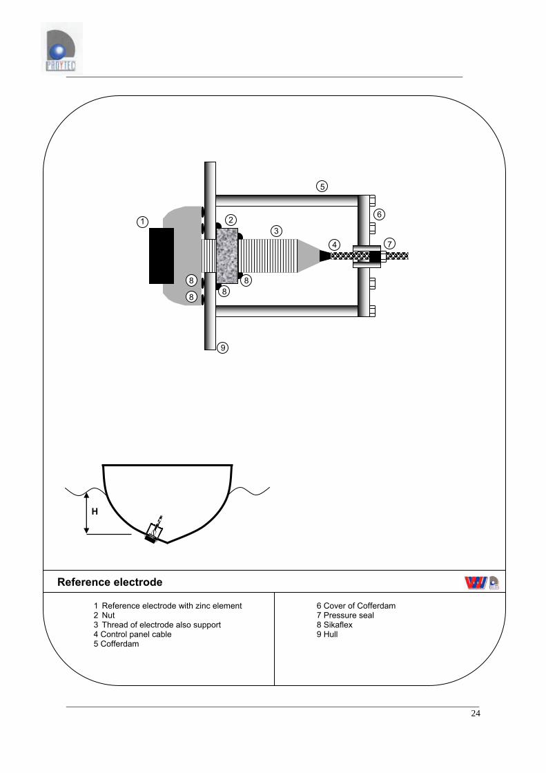
9.5 Installation instructions: Reference electrode • The electrode will be located in an area selected by PROYTEC on an installation plan. When
necessary PROYTEC will select an alternative location at the time of installation. Normally the
electrode is located in the stern between 1.5 and 3 meters in front of the anode in the submerged
areas where there is no chance of being scraped in port or by fishing nets.
• Drill a hole a tiny bit larger (1mm) than the diameter of the threads.
• Securely fasten the electrode with beads/lines of Sikaflex avoiding any possibility for water to
enter the boat/vessel.
• Once fastened with Sikaflex, and the interior nut has been fastened, make three beads with
Sikaflex as indicated in position number 8 of the diagram.
• In metal hulled boat/vessels this will be done in a cofferdam to ensure water tightness. With a
special pressure seal we adjust the proper length from the electrode through the cofferdam.
• When bundling the electrode cable with other cables, avoid the red cable of the anode prevent
interference. The minimum distance of separation should be 1 meter. This also applies to cables
with alternating current.
• The 16mm² cable should be connected as close to the electrode as possible, cutting the extra
cable from the electrode.
• The splice on the 16mm² cable (blue) will be done above the bilge water level and sealed with
shrink tubing or other sealing method (in an easily accessible location where periodic inspections
can be performed).
• Fastening of the electrode with Sikaflex should be done based on the standards of Sika
Company.

23
1. CABLE 2. NUT 3. ZINC VS. Frontal View
TIPO L1 L2MAX L3 L4 H1 H2 H3 Ø
30 X 50
40 X 50
30 X 80
40 X 80
24
1 Reference electrode with zinc element 2 Nut 3 Thread of electrode also support 4 Control panel cable 5 Cofferdam
1 2 3
4
5
6
7
8 8
8
8
9
6 Cover of Cofferdam 7 Pressure seal 8 Sikaflex 9 Hull
Reference electrode
H
3
1 2
4
5
67
8 8
889
8
9
3
1 2
4
5
6
7
8 888
8
25
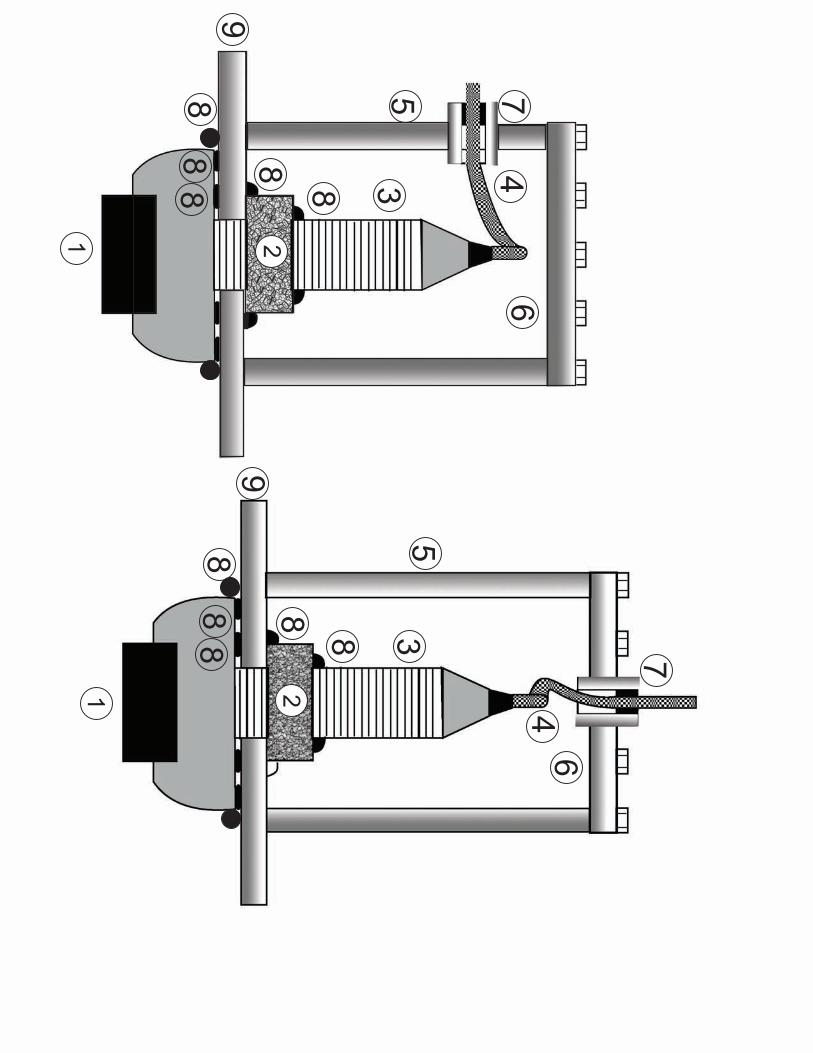
9.6 Installation instructions: Control panel • The light panel consists of two elements: a reference electrode and an electronic panel.
• Unite the power (red and black, red +, black- cables) to the battery (12 or 24V) and to the copper
union plate on the bridge/control room through use of an in-line fuse (1 amp) on the positive side
of the battery terminal. Connect the brown cable to the copper union plate/bus bar for the
bridge/control room. Connect the blue cable to the reference electrode (using the shielded cable).
• The corrosion level reading is taken by pushing a test button for at least 5 seconds. This will light
a light a series of LED’s which will indicate the amount of corrosion the boat/vessel is undergoing.
The interpretation of the lights is as follows:
• Green light: Protection
• Yellow light: Over protected
• Red light: Corrosion
• The button should not be permanently pushed because it could overheat the microprocessor,
drain the battery and the electrode.
• Adjusting the system through use of the light panel Once the boat is in the water and not before, power is connected to the regulator and the light panel.
Push the red button for a few seconds and adjust the power output of the regulator with the switch in
the “Port” position until one of the first three green lights turn on. The lights referred to are counted
from the left to the right. Once the minimum current for the Port setting is finished, then the same
procedure should be followed while under navigation by switching to the “Navigate” position. It is only
necessary for the first one or two green lights to light up during this adjusting period while under
navigation. When a boat is placed in the water, it takes a while for it to find its proper point of rest. It
will probably be necessary to readjust after a few hours. After that point is no longer necessary to
make adjustments. It is sufficient to leave the regulator switch in the Port or Navigate position at the
appropriate time.
Note: It is possible that after a few months the current needs may have changed due to falling paint.
A normal adjustment is all that is needed following the preceding steps.
• Switch conmutador Normally the Port position is toward the back or to the left and the Navigate position is forward or to
the right.
26
• State of protection Anytime it is necessary to see the state of protection of the boat, press the button on the light panel
until one of the LED’s light up: if green, the boat is protected (correct), if yellow the boat is
overprotected and if red the boat is receiving corrosion. In both of the last two cases a very light
readjustment would be necessary. The amp meter should not indicate significantly different reading
from the ones before: Port and Navigate and if this does not solve the problem then a check of the
light panel will be necessary.
• In case of a red light The first thing that should be done if a red light is indicated is look at the amp meter to see if it has
stopped sending current to the anodes or if the current has dropped considerably. This is probably the
cause of the anomaly. In this case the regulator and circuit should be checked including: fuses, the
anode, anode cable, the union plates on the bridge and in the engine room and the grounding cables
which connect to them.
Once the problem is solved, the green light on the panel should appear once again in the same or
similar position to the original position. This should be the case if the amp meter indicates the same or
similar current as before (before the problem). In case the amp meter indicates a significant
difference watch the yellow light. The problem should be looked for in the corrosion meter.
• Verification of the Corrosion meter Inside the light panel there is a 5 amp fuse. If the fuse burns out, this could be the cause for a yellow
light reading of “over protection” incorrectly. The problem is solved by changing the fuse. The green
light should then reappear.
In any case and electrician should be called to review the installation and all the connections to the
union plates to ensure that the panels do not get damaged.
The system works with a maximum of 200mA, so if a 5 amp fuse is burned out, it means there are
strong negative currents returning through the equipment. The most likely cause is that the negative
pole of the battery has not been connect to the union plates.
A yellow light can also be indicated even if the boat is not over protected due to the following causes:
a rupture of the blue cable from the reference electrode, a broken electrode due to a bump. In case
the cause of the anomalies does not appear there is a simple solution to find out if the panel is
damaged.
27
Loosen the brown and blue panel cables and press the test button. The light that should appear is
the yellow LED. If the blue and brown cable are pressed together tightly, once disconnected from the
installation, the boat should indicate a green light.
And lastly, if everything is ok and a red light is indicated (corrosion) with a normal intensity, then it is
possible that there is interference. Electronic interference dirties the signal in the panel and gives a
false corrosion reading. This could cause one to raise the regulator to a dangerously high level
unnecessarily. This could damage the equipment. In this case it is necessary for a technician to
measure the potentials of the boat using an electrode of Silver – Silver-chloride. Once confirmed we
have equipment to help shield the panel from electronic noise in order to get a correct reading.
The panel has a 35V Y4.700 microfaradios condenser next to the entrance of the power source.

28
7 Reference electrode 8 Union plate/bus bar – Engine room 9 Schematic – Union plate/bus bar – Engine room 10 Splice 11 Condenser (35V. – 4.700 uF)
1 Control panel 2 LED’s 3 Test Button 4 Fuse - 2A 5 Battery 12V-24V 6 Union plate/bus bar - Bridge
Control panel
4 5
6
Black -
C: Brown -
B: Black -
A: Red + D: Isolated +
CORROSION CHECKING EQUIPMENT
W.W.I. PROYTEC
CORROSION PROTECTION OVER PROT.
TEST
1
2
3
7
8
9
E: Black -
10
10
10
10
11
F: Green / Yellow
Minimum cable width: A: 2,5 mm2 B: 2,5 mm2 C: 10 mm2 D: E9-PR-DB1, E9-PR-DC: 5 mm2 (SHIELDED) E9-PR-DD, E9-PR-DD1: 7,5 mm2 (SHIELDED) E9-PR-DD2, E9-PR-DD3: 10 mm2(SHIELDED) F: E9-PR-DB1, E9-PR-DC, E9-PR-DD, E9-PR-DD1: 25 mm2 E9-PR-DD2, E9-PR-DD3: 50 mm2
Blue +
29
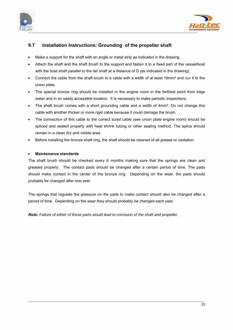
9.7 Installation Instructions: Grounding of the propeller shaft
• Make a support for the shaft with an angle or metal strip as indicated in the drawing.
• Attach the shaft and the shaft brush to the support and fasten it to a fixed part of the vessel/boat
with the boat shaft parallel to the tail shaft at a distance of D (as indicated in the drawing).
• Connect the cable from the shaft brush to a cable with a width of at least 16mm² and run it to the
union plate.
• The special bronze ring should be installed in the engine room in the farthest point from bilge
water and in an easily accessible location. It is necessary to make periodic inspections.
• The shaft brush comes with a short grounding cable and a width of 4mm². Do not change this
cable with another thicker or more rigid cable because it could damage the brush.
• The connection of this cable to the correct sized cable (see union plate engine room) should be
spliced and sealed properly with heat shrink tubing or other sealing method. The splice should
remain in a clean dry and visible area.
• Before installing the bronze shaft ring, the shaft should be cleaned of all grease or oxidation.
• Maintenance standards The shaft brush should be checked every 6 months making sure that the springs are clean and
greased properly. The contact pads should be changed after a certain period of time. The pads
should make contact in the center of the bronze ring. Depending on the wear, the pads should
probably be changed after one year.
The springs that regulate the pressure on the pads to make contact should also be changed after a
period of time. Depending on the wear they should probably be changed each year.
Note: Failure of either of these parts would lead to corrosion of the shaft and propeller.
30
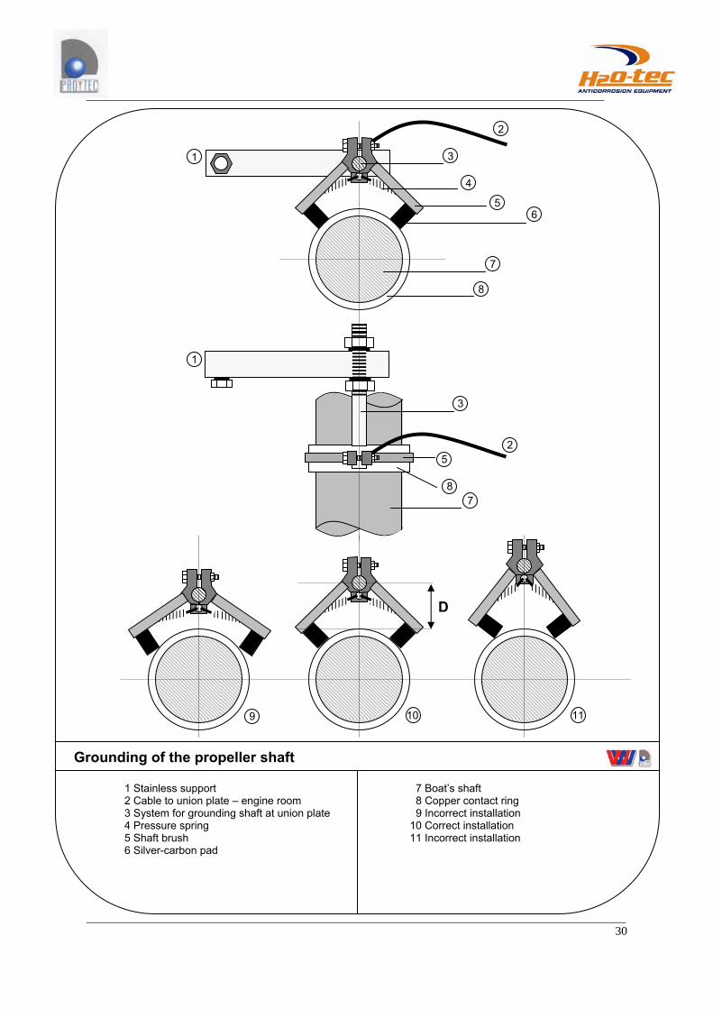
1 Stainless support 2 Cable to union plate – engine room 3 System for grounding shaft at union plate 4 Pressure spring 5 Shaft brush 6 Silver-carbon pad
7 Boat’s shaft 8 Copper contact ring 9 Incorrect installation 10 Correct installation 11 Incorrect installation
Grounding of the propeller shaft
D
1
2
3
4
5 6
7
8
9 10 11
1
2
3
5
7 8

31
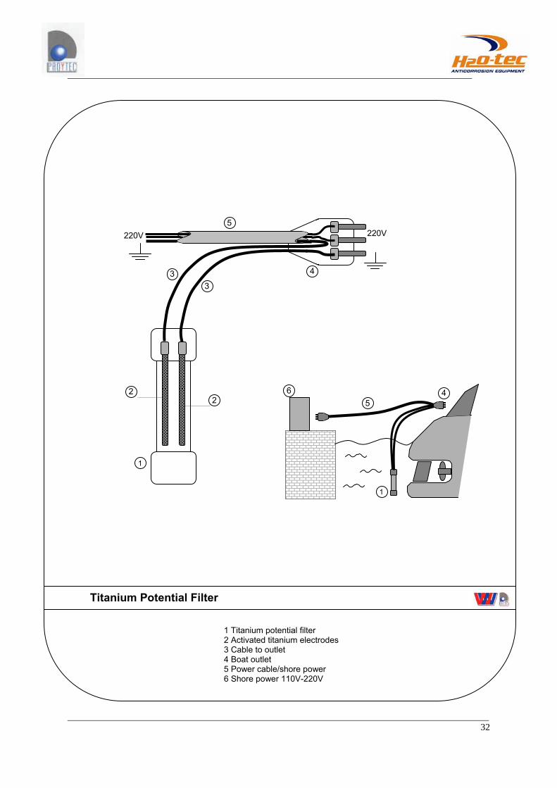
9.8 Installation Instructions: Titanium potential filter • The cables of the titanium potential filter should be connected as indicated in the installation
diagram.
• In case the boat receives current of 220V or 380V, the titanium power filter should ALWAYS
remain submerged in salt water.
32
1 Titanium potential filter 2 Activated titanium electrodes 3 Cable to outlet 4 Boat outlet 5 Power cable/shore power 6 Shore power 110V-220V
Titanium Potential Filter
220V 220V
1
2 2
3 3 4
5
1
4 5
6