ps150 boost manual 2007.08.15 -...
TRANSCRIPT
PS150 BOOST INSTRUCTIONS FORINSTALLATIONOPERATIONSERVICECopyright © 2004, 2005, 2006, 2007 by BERNT LORENTZ GmbH&CoKG, all rights reserved.
2
1 INTRODUCTION .......................................................... 2
2 WARNINGS ................................................................. 3
3 DIMENSIONS .............................................................. 3
4 SYSTEM REPORT FORM ............................................ 4
5 INSTALLATION CONTROLLER PS150 ....................... 5
5.1 General Information ................................................ 55.2 Warnings to Installer ............................................... 55. 3 Mechanical Installation ........................................... 55.2 Technical Data ......................................................... 55.4 Electrical Installation-Terminals ............................. 65.5 Monitoring ................................................................ 65.6 Basic Operating Constraints ................................... 7
6 PLUMBING SYSTEM DESIGN...................................... 7
7 MOUNTING YOUR PUMP ............................................ 8
8 INSTALLATION IN DRILLED WELL CASINGS ............. 9
9 ELECTRICAL WIRING.................................................. 9
9.1 General .................................................................... 99.2 Grounding and Lightning Protection ....................... 99.3 System Wiring for 12 V Battery Installation ........... 109.4 System Wiring for 24 V Battery Installation ........... 109.5 System Wiring for 12-24 V Solar Direct Operation 119.6 Power Control for Solar Direct Operation ............. 11
10 WATER LEVEL AND FLOW CONTROL ................... 12
11 PRESSURIZING SYSTEMS ...................................... 12
11.1 Pressure Switch Wiring ....................................... 13
12 MAINTENANCE ....................................................... 13
13 TROUBLESHOOTING .............................................. 14
14 WARRANTY ............................................................ 15
CAUTIONrecommended to avoid disfunc-tion or premature ageing of thepump etc.
WARNINGdisregard might lead to injury ordamage the installation
Symbols
Thank you for purchasing a LORENTZ PUMP. We seta new standard for quality and economy in solarpumping. It incorporates the best solar pump technolo-gies that were very expensive until its introduction in2002.
1 INTRODUCTION
PS150 BOOST is a highly efficient pump systemwhich provides city water pressure, anywhere. It iseconomical for domestic water supply, (drip-) irrigation,livestock, water transfer to remote places and manyother applications. It is a surface pump which cannotbe submersed.
The pump of PS150 BOOST is a positive displace-ment vane type pump.
The PS150 BOOST brushless DC motors are speciallymade for this system. The motor is using very ad-vanced raw earth magnet technology, hand madewiring for highest copper density and does not needwearing brushes. This results in an exceptional highefficiency with low temperature dissipation.
PS150 BOOST can either be used in a battery systemwith voltages of 12, 24V or alternatively it can beoperated as a solar direct system using the sameController PS150.
The solar battery is charged up during daylight hoursusing the integrated charger of the PS150 controller.The charger works effectively during reduced sunlightconditions when direct pump operation is not possible.
The energy stored in the battery is available to operatethe pump at any time, day or night and during periodsof bad weather.
Extended bad weather periods with water demands ofup to 10m3 per day will be reliably bridged due to thehigh system efficiency even with low capacity batteries.
The pump is manufactured from non-corrosivematerial (stainless steel / brass / aluminum).
Before you begin Check the modelnumbers of all the components of yoursystem, and verify that they are the itemsthat you ordered. Also check against thePUMP specifications and performancecharts (end of this manual) to be sure the
system is appropriate for your application. If you thinkyou may have the wrong pump for your application, callyour supplier immediately.
Please fill in the SYSTEM REPORT. This will be essen-tial information if any problems occur.
CONTENTS
3
2 WARNINGS
Failure to followthese instruc-tions will voidthe warranty.
PS150 BOOST IS A DC VANE TYPE PUMP. It is differentfrom other pumps.
This is not a submersible pump.Before beginning installation procedures, theseinstallation and operating instructions should bestudied carefully.
The installation and operation should also be inaccordance with local regulations and acceptedcodes of good practice.This INSTRUCTION MANUAL contains maintenanceinformation, and is the property of the pump owner
Please give this manual to the pump owner or mainte-nance personnel when you are finished!
Please note: Thepump must onlybe used in cleanfresh water.
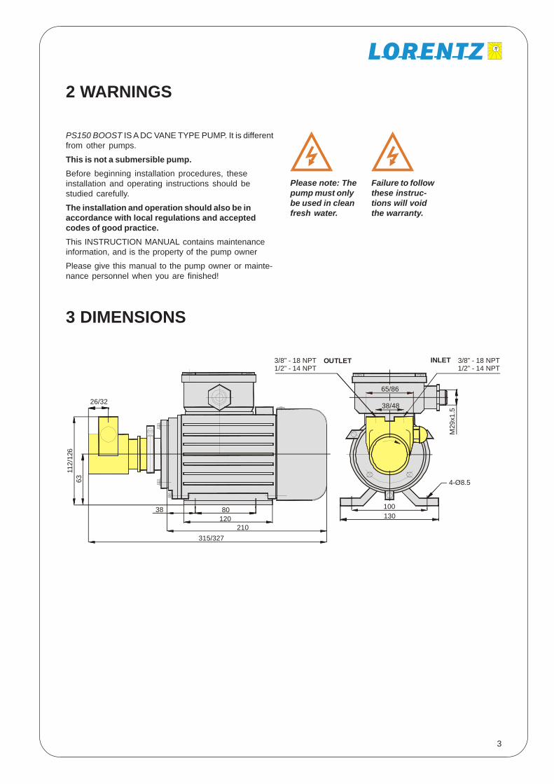
3 DIMENSIONS
315/327210
100
38/48
65/86
M29
x1.5
3/8” - 18 NPT1/2” - 14 NPT
3/8” - 18 NPT1/2” - 14 NPT
INLETOUTLET
1301208038
112/
126
26/32
63 4-O8.5

4
4 SYSTEM REPORT FORM
Before you start, indicate your systems datas.
System Voltage V
Date of Purchase
Purchased from
Quantity of Batteries
Battery Type
Quantity of Solar Modules (panels)
Solar Module Type
Pump Model
Pump Serial #
Controller Model
Controller Serial #
Installer: Record the following
Installation Date
Installed by
Cut-in Pressure bar / PSI
Cut-out Pressure bar / PSI
Additional Suction Lift m / ft
Total Pipe Length, Pressure Side m / ft
Total Pipe Length, Suction Side m / ft
Pipe
Size
Type
5
5 INSTALLATION CONTROLLER PS150
5.1 General Information> Controlling and monitoring of the motor
> Integrated MPP-tracking and LVD battery protection
> LVD protection (low voltage disconnect) for 12 and24V batteries
> Check and display the operating states
> Two control inputs for float- or pressure switches,remote control, etc.
> 92% max. efficiency (motor + controller)
> Adjustable maximum RPM setting, refer to pumpmanual for details
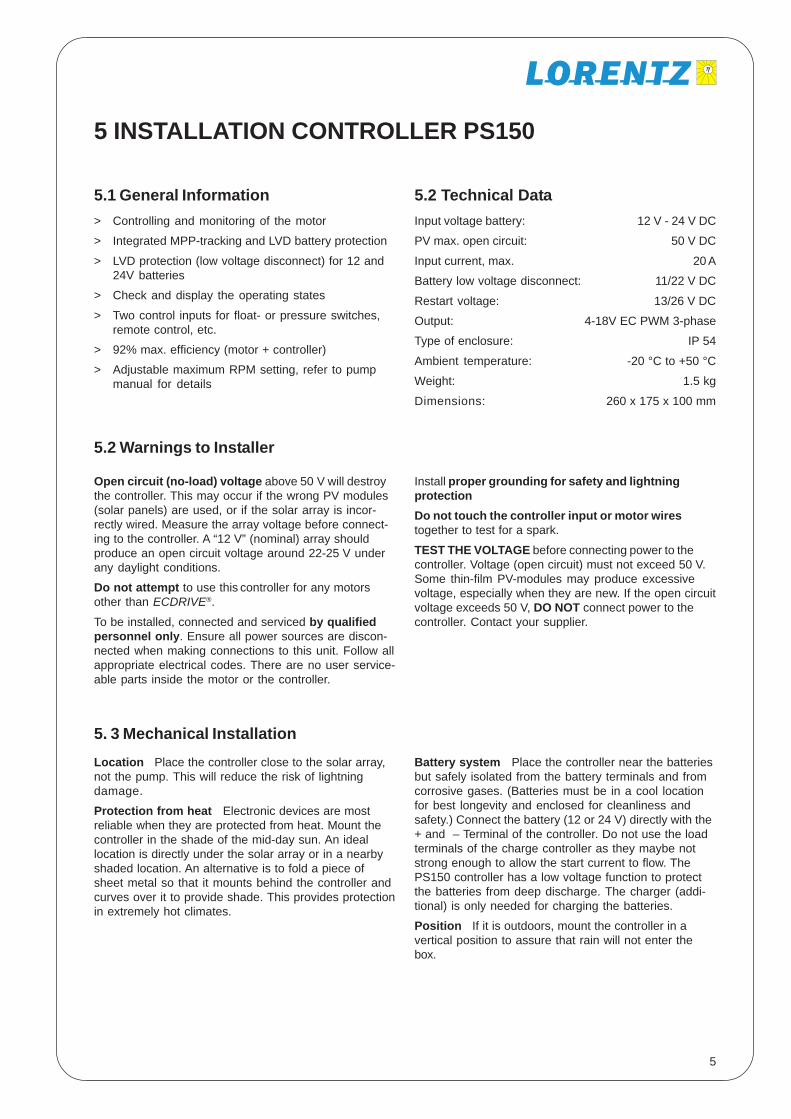
5.2 Technical DataInput voltage battery: 12 V - 24 V DC
PV max. open circuit: 50 V DC
Input current, max. 20 A
Battery low voltage disconnect: 11/22 V DC
Restart voltage: 13/26 V DC
Output: 4-18V EC PWM 3-phase
Type of enclosure: IP 54
Ambient temperature: -20 °C to +50 °C
Weight: 1.5 kg
Dimensions: 260 x 175 x 100 mm
Open circuit (no-load) voltage above 50 V will destroythe controller. This may occur if the wrong PV modules(solar panels) are used, or if the solar array is incor-rectly wired. Measure the array voltage before connect-ing to the controller. A “12 V” (nominal) array shouldproduce an open circuit voltage around 22-25 V underany daylight conditions.
Do not attempt to use this controller for any motorsother than ECDRIVE®.
To be installed, connected and serviced by qualifiedpersonnel only. Ensure all power sources are discon-nected when making connections to this unit. Follow allappropriate electrical codes. There are no user service-able parts inside the motor or the controller.
5.2 Warnings to Installer
Location Place the controller close to the solar array,not the pump. This will reduce the risk of lightningdamage.
Protection from heat Electronic devices are mostreliable when they are protected from heat. Mount thecontroller in the shade of the mid-day sun. An ideallocation is directly under the solar array or in a nearbyshaded location. An alternative is to fold a piece ofsheet metal so that it mounts behind the controller andcurves over it to provide shade. This provides protectionin extremely hot climates.
5. 3 Mechanical Installation
Install proper grounding for safety and lightningprotectionDo not touch the controller input or motor wirestogether to test for a spark.
TEST THE VOLTAGE before connecting power to thecontroller. Voltage (open circuit) must not exceed 50 V.Some thin-film PV-modules may produce excessivevoltage, especially when they are new. If the open circuitvoltage exceeds 50 V, DO NOT connect power to thecontroller. Contact your supplier.
Battery system Place the controller near the batteriesbut safely isolated from the battery terminals and fromcorrosive gases. (Batteries must be in a cool locationfor best longevity and enclosed for cleanliness andsafety.) Connect the battery (12 or 24 V) directly with the+ and – Terminal of the controller. Do not use the loadterminals of the charge controller as they maybe notstrong enough to allow the start current to flow. ThePS150 controller has a low voltage function to protectthe batteries from deep discharge. The charger (addi-tional) is only needed for charging the batteries.
Position If it is outdoors, mount the controller in avertical position to assure that rain will not enter thebox.
6
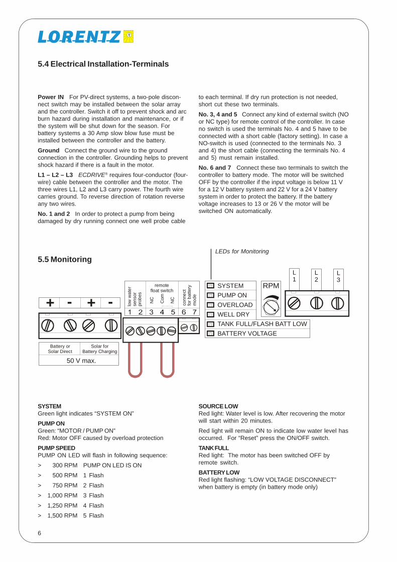
Power IN For PV-direct systems, a two-pole discon-nect switch may be installed between the solar arrayand the controller. Switch it off to prevent shock and arcburn hazard during installation and maintenance, or ifthe system will be shut down for the season. Forbattery systems a 30 Amp slow blow fuse must beinstalled between the controller and the battery.
Ground Connect the ground wire to the groundconnection in the controller. Grounding helps to preventshock hazard if there is a fault in the motor.
L1 – L2 – L3 ECDRIVE® requires four-conductor (four-wire) cable between the controller and the motor. Thethree wires L1, L2 and L3 carry power. The fourth wirecarries ground. To reverse direction of rotation reverseany two wires.
No. 1 and 2 In order to protect a pump from beingdamaged by dry running connect one well probe cable
SYSTEMGreen light indicates “SYSTEM ON”
PUMP ONGreen: “MOTOR / PUMP ON”Red: Motor OFF caused by overload protection
PUMP SPEEDPUMP ON LED will flash in following sequence:
> 300 RPM PUMP ON LED IS ON
> 500 RPM 1 Flash
> 750 RPM 2 Flash
> 1,000 RPM 3 Flash
> 1,250 RPM 4 Flash
> 1,500 RPM 5 Flash
5.5 Monitoring
5.4 Electrical Installation-Terminals
LEDs for Monitoring
SOURCE LOWRed light: Water level is low. After recovering the motorwill start within 20 minutes.
Red light will remain ON to indicate low water level hasoccurred. For “Reset” press the ON/OFF switch.
TANK FULLRed light: The motor has been switched OFF byremote switch.
BATTERY LOWRed light flashing: “LOW VOLTAGE DISCONNECT”when battery is empty (in battery mode only)
to each terminal. If dry run protection is not needed,short cut these two terminals.
No. 3, 4 and 5 Connect any kind of external switch (NOor NC type) for remote control of the controller. In caseno switch is used the terminals No. 4 and 5 have to beconnected with a short cable (factory setting). In case aNO-switch is used (connected to the terminals No. 3and 4) the short cable (connecting the terminals No. 4and 5) must remain installed.
No. 6 and 7 Connect these two terminals to switch thecontroller to battery mode. The motor will be switchedOFF by the controller if the input voltage is below 11 Vfor a 12 V battery system and 22 V for a 24 V batterysystem in order to protect the battery. If the batteryvoltage increases to 13 or 26 V the motor will beswitched ON automatically.
L1
L2
L3
++ -- low
wat
erse
nsor
prob
es
conn
ect
for b
atte
rym
ode
remotefloat switch
Battery orSolar Direct
50 V max.
Solar forBattery Charging
NC
Com
NC
SYSTEMPUMP ONOVERLOADWELL DRYTANK FULL/FLASH BATT LOWBATTERY VOLTAGE
RPM

7
5.6 Basic Operating Constraints
1. PUMP IS NOT SUBMERSIBLEYour pump must NOT be submerged in water, or rainedor dripped on.
2. WATER MUST BE FILTEREDYour pump is a PRECISION MACHINE. Traces of sand,clay, rust or other solids will cause rapid wear orimmediate damage, just as they would in your automo-bile engine. lf your water is CRYSTAL CLEAR ALL THETIME, our Fine Intake Strainer will provide sufficientprotection. lf you have an intake strainer already, it isprobably not fine enough - openings must be no morethan several hairs wide -, or additional filtration isrequired. Since water conditions are subject to change,it is good insurance to use a filter regardless. Manydealers refuse to sell our pumps without a filter since itminimizes call backs.
Our 30 INCH INTAKE FILTER/FOOT VALVE is necessaryfor pumps lowered into wells.- Otherwise our INLINEFILTER is best, installed close to the pump’s intake. lffilters are expected to clog often, maintenance may beminimized by plumbing two or more filters in parallel.The INLINE FILTER has a clear bowl so its conditionmay be observed. KEEP SPARE CARTRIDGES HANDY!FILTER CARTRIDGES are available from your dealer orthe factory. 9 7/8 inch cartridges for the INLINE filter mayalso be obtained from local water system suppliers.The 10-20 -micron “spun polypropylene” type is best.Paper filters have less capacity. The kind that look likestring has more resistance to flow. Carbon taste andodor cartridges have less capacity for dirt, more
resistance to flow, and cost more. Use them only if youhave, taste and odor problems.
A filter cartridge may look clean and still be clogged,due to fine silt embedded in the fibers. If the pump,becomes increasingly noisy over time, it is usually dueto a clogging filter cartridge. On the other hand, acartridge that looks discoloured may not be clogged, Aslong as your pump runs quietly, the filter is OK. Usepump noise to indicate the need to change cartridges.
IRON PIPE OR FITTINGS will introduce abrasive rustparticles if installed on the intake side of the pump(they rust, every if galvanized). Pipe that is dirty inside(even new pipe) or has mineral deposits in it will alsointroduce dirt. Dirt is introduced as pipe joints areassembled, especially in a trench. Therefore, makesure inlet lines and fittings are FLUSHED CLEAN beforehooking up to pump.
The INLINE FILTER may have a red push button valve torelease pressure for maintenance. If filter is placedmore than a few feet higher than water source (atlowest level) the suction may pull the valve open andintroduce air. Prevent this by sealing around the pushbutton with silicone sealant or epoxy, or replace thebutton with a nut, tightened down,
3. PUMP MUST NOT RUN DRYWater is the lubricant for your pump. lf it runs com-pletely dry, it will overheat and fail. As an option you caninstall a well probe to terminals 1-2 to shut the pumpoff if water source is low.
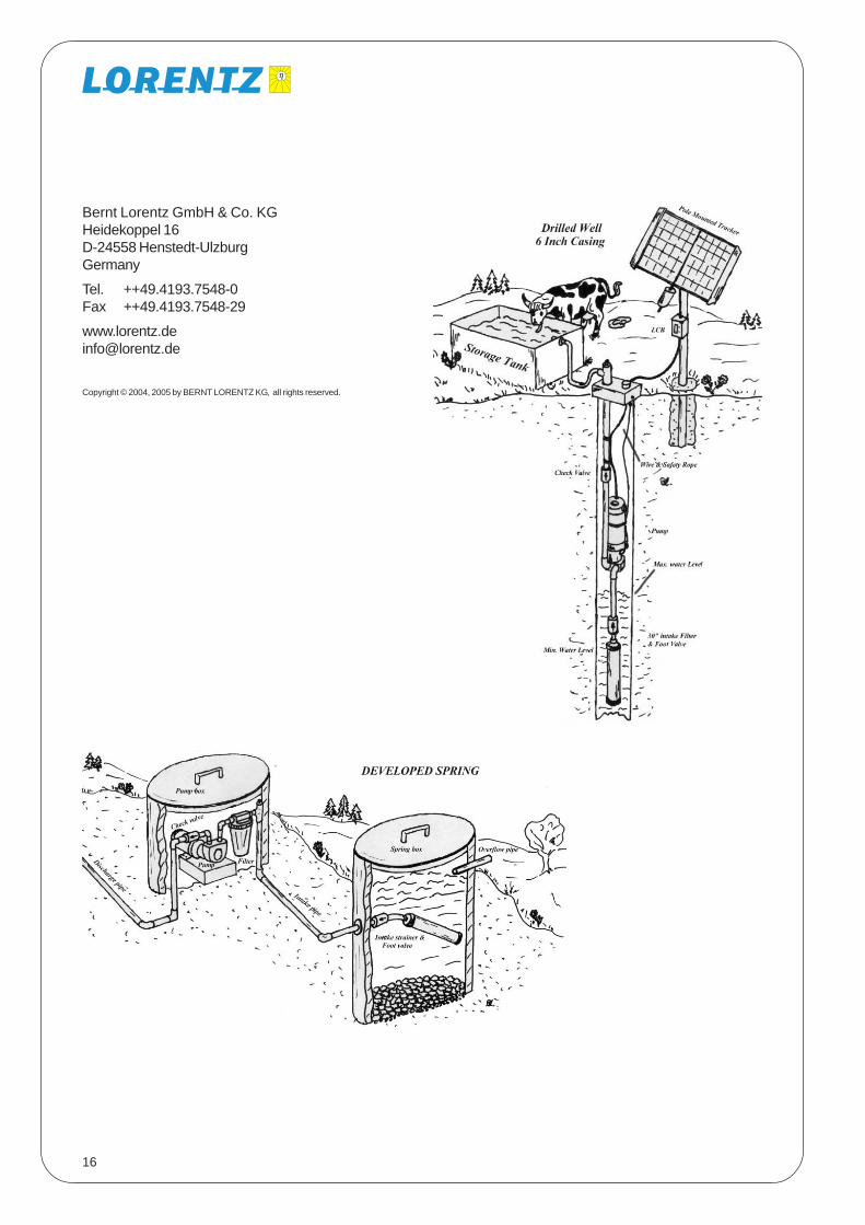
6 PLUMBING SYSTEM DESIGN
If you are not experienced in water supplydesign and installation, you may wish toseek professional assistance. Manypeople are surprised to find how “com-plex” water system design can be. See
diagrams on p. 16, for typical groundwater installations.
MINIMIZE SUCTION LIFT to max. 3 m total pressureloss (2 m for pumps with flow rate greater than 400l/h).The practical suction limit for any pump is 6m (20vertical ft) at sea level (subtract 0.3 m/1 ft for every 300m/1,000 ft of elevation). The more you minimize suctionlift, the more reliable and quiet your pump will be. Justbe sure the motor will not be submerged if the waterlevel rises, or it will be ruined. Your pump may beplaced DOWNHILL from your water source, if feasible.
YOUR INTAKE PIPE may run any reasonable horizontaldistance, although it is BEST TO KEEP IT SHORT. (Weknow of installations where the pump is placed 200 ft
from the water source, using 1 1/2" pipe.) USE LARGEPIPE for the intake (1 to 1 1/2" for larger Booster Pump).
Slope the intake line from the water source UP towardthe pump. AVOID HUMPS in the intake line. They trap airpockets which can block the flow. AVOID LEAKS INSUCTION LINE. They are hard to locate and will causeconstant problems.
INTAKE PIPE MUST BE SIZED GENEROUSLY to allow nomore than a slight pressure drop at peak flow rate, orpump will be noisy and will wear rapidly. USE PIPEREDUCER FITTINGS to adapt your pump’s inlet oroutlet to larger pipe size where necessary. Excessivepipe sizing will do no harm!
INTAKE MUST NOT BE RESTRICTED by undersizedpipe, excessive suction lift, or a CLOGGED FILTER.Excessive suction at the pump intake causes CAVITA-TION (formation and implosion of vapor bubbles). Thiscauses very loud buzzing noise and RAPID PUMP
8
WEAR. A slight buzzing noise is acceptable, if it cannotbe avoided.
DO NOT USE THIN WALL HOSE or soft tubing on thepump’s intake. It may collapse under suction andrestrict the flow. Do not use polyethylene pipe (blackflexible) for the suction either. It is prone to slightleakage at the fitting
INLINE FILTER should be mounted HORIZONTALLY andas low as possible. This prevents any air trapped in itfrom blocking the water flow. Be sure to leave somespace below it for a pan, to catch water when replacingthe filter cartridge.
FOOT VALVE is a check valve installed at the waterintake. It is required in any case where the pump islocated higher than the low water level in the source.We recommend a high quality spring loaded type toavoid loss of prime. A check valve allows water to flowone way and not the other. Be sure to install it the rightway!
New pumps are packed with foam plugs to preventcontamination. REMOVE FOAM PLUGS BEFORECONNECTING PIPES.PRIMING YOUR PUMP: Priming a pump means fillingits intake and suction line completely with water. Thismust be done if the pump is mounted higher than the
Locate your pump in a cool place. Do not allow directexposure to sunshine during operation, or the motormay overheat. Allow free flow of air around the motorfor cooling. SHELTER IT FR.OM RAIN AND SUN, or itwill be a mess in a few years.
The pump may be mounted horizontally or vertically. lfvertically, FACE THE PUMP HEAD DOWNWARD. RIGIDMOUNTING IS NOT required in most installations. In anon battery system, starting is gradual and the pumpdoes not jerk with the start. In a battery system, it willjerk slightly, but simply mounting it to a small woodenboard is sufficient to stabilize it. The pump may behung vertically on a rope. Observe the pump and seethat it is not likely to overstress or loosen pipes as itstarts. DO NOT mount the pump directly to a wall orwood floor in your home. It will increase the noise.
CHANGING PUMP HEAD POSITION: lf you wish to facethe pump’s fittings sideways or downwards, please do.You may rotate pump head to a different position byloosening the clamp screw that secure the pump to themotor. BEFORE installing the pump, drop a teaspoonof water into the inlet and run the pump.
HANDLE YOUR PUMP CAREFULLY! Never hammer onit, clamp it in a vice or drop it.
To PREVENT FREEZING of exposed pipesyou might consider the primitive method ofdrilling a small “weep hole” in the outletpipe, below ground level. The pipe Willdrain when pumping stops but a small
amount of water will be wasted during pumping. Setthe outlet pipe to spill into the top of the tank so that thetank will not drain, or install a check valve and “vacuumbreaker” to allow pipe to drain.
Water WILL drain back through the pump if allowed to,but it will do so slowly. lf this is desired, do not use anycheck valves or foot valve. Pump must have suctiondraw of no more than about 3 m/10 ft, however. lf pumpdrainage is required, position pump vertically (headdownward) or horizontally with intake and outlet facingdownward.
Take every precaution to PREVENT pump freezing. Theforged brass pump head will survive most light freezes,but a hard freeze may damage it. lf you insulate yourpump for freeze protection, keep the motor exposed soit won’t overheat.
7 MOUNTING YOUR PUMP
Plumbing System Design Continued
water source. A removable plug or a valve must beinstalled at the highest point is in the suction plumbing.Prime the pump and intake line by pouring water intothe opening until it is completely full. Your foot valveprevents loss of prime by not allowing water to flowback into the water source.
Your pump will create enough vacuum to SELF-PRIMEto around 3 m/10 ft (less at high elevations), but onlywhen it is in new condition and wet inside. A primingplug is always recommended if the pump is to belocated higher than the water source. You may use agood quality ball valve instead of a plug, if frequentpriming is expected.
A CHECK VALVE AT THE PUMP OUTLET is required ifthere is more than a 30 ft lift above the pump, or in anypressurizing system. This allows the pump to starteasier. It also prevents back flow when changing filtercartridges.
PIPE UNIONS: lf you run rigid piping (copper or PVC)directly to the pump, unions are required. Unions makepump replacement easy, without the need to cut and resolder or re glue the pipe. “Copper Flex Connectors”commonly used for water heaters may be used in-stead.
9
8 INSTALLATION IN DRILLED WELL CASINGS
INSIDE A 6 INCH WELL CASING, SPECIAL ELBOWSADAPTERS are required. The elbows fit 1/2"polyethylene (black flex) pipe. MEASURE CAREFULLYto determine the length of pipe you need. SUBTRACT1.5% TO ALLOW FOR PIPE AND ROPE STRETCH.
Assemble according to diagram. A priming plug is notneeded. Before lowering the pump, place the intakeinto a bucket of clean water and run the pump untilwater exits. Now it is primed. A “pitless adapter” may beoptimum for freeze protection. Check with your localwell supplier for details.
POLYETHYLENE PIPE comes in rolls, and is inexpen-sive and quite freeze tolerant. Use with plastic adaptersand secure with ALL STAINLESS hose clamps (obtainsuch clamps from a pipe supplier rather than automo-tive supplier). lf pipe does not stretch tightly over fittings,warm it with a torch or hot water then tighten clampsfirmly with a wrench. Keep extra clamps handy in caseyou strip one.
9 ELECTRICAL WIRING
WIRE SIZING: DON’T CHEAT YOURSELF with under-sized wire! Splice it to a larger size of wire if your wirerun is longer than 2 m / 7 ft. A wire sizing table for themotor cable is shown on page 10 of this manual.Consult a low voltage wire size chart to size the cablesize from tha array to the controller or call your dealer orthe factory for recommendations. Excessive voltagedrop will slow the pump down, but if it is unavoidable,don’t worry. It will NOT cause any harm to the motor.The cable ends are labelled 1, 2, 3. Connect them inthis sequence with the pump controller to have thecorrect direction of turning (clockwise). Check from thefan of the motor. Looking on the fan of the motor thedirection is counter clock wise see also the arrow.Changing the polarity of the DC ( plus & minus) input ofthe controller will not change the direction of turning!Only changing two of the three motor phases will do.
In case the motor turns in the wrong direction exchangeany of the three motor cables. Turning in the wrongdirection will not damage the pump if done for a shorttime. Reverse the wires if necessary so that pumpturns CLOCKWISE looking from purtip end.
If water flow becomes blocked, or if the pump jams orfreezes and cannot turn freely, the motor will drawexcessive current. A fuse or circuit breaker will thenbreak the circuit. The controller has an overloadprotection but in case of a short circuit you will protectthe batteries.
Install a 20 Amp fuse or breaker. Install the fusebetween the battery and the pump controller.
FUSES: Use a “time delay” type installed into a raintight disconnect switch available at any electric sup-plier. An automotive in-line fuse holder is fine for 12 or24 V systems. Automotive blade fuses (type ATC) arepreferred over glass fuses. They have sufficient timedelay. (Time delay glass fuses are available fromELECTRONIC suppliers only, not automotive.) Usegood quality fuse holders, protected from weather.Keep spare fuses handy.
CIRCUIT BREAKERS: Most AC breakers cannot beused for low voltage DC circuits. It may be ordered fromyour PV dealer or from an electric supplier.
9.1 General
9.2 Grounding and Lightning Protection
A long wire run may act like an antenna, receivinginduced surges of high voltage when lightning ispresent. Proper grounding will greatly reduce risk oflightning damage to your power system.
A proper ground system consists of a minimum of one2.5 m / 8 ft copper plated ground rod driven into theground, preferably in a moist spot close to the PV array.Or, if you have a steel well casing, drill and tap a bolthold to make good contact to it.
In a dry, lightning prone location, use more than oneground rod at least 3m / 10 ft. apart. Bury bare copperwire between them. Use min, 4mm2 / #8 ground wire(larger for distances exceeding 20 ft.). In a rocky
location, where ground rods can’t be driven, bury (asmuch as feasible) 45m / 150 feet (total) of bare copperwire, radiating out in two or more directions from the PVarray. Try to contact moist earth as much as possible.Use only the copper or bronze electrical connectorsdesigned for grounding application, and BE SURE ALLCONNECTIONS ARE TIGHT.
Connect your ground system to the METALLIC FRAMEof your PV array via min. 4mm2 / #8 copper wire. Alsoground metallic support structures and electricalenclosures.
10
9.4 System Wiring for 24 V Battery Installation
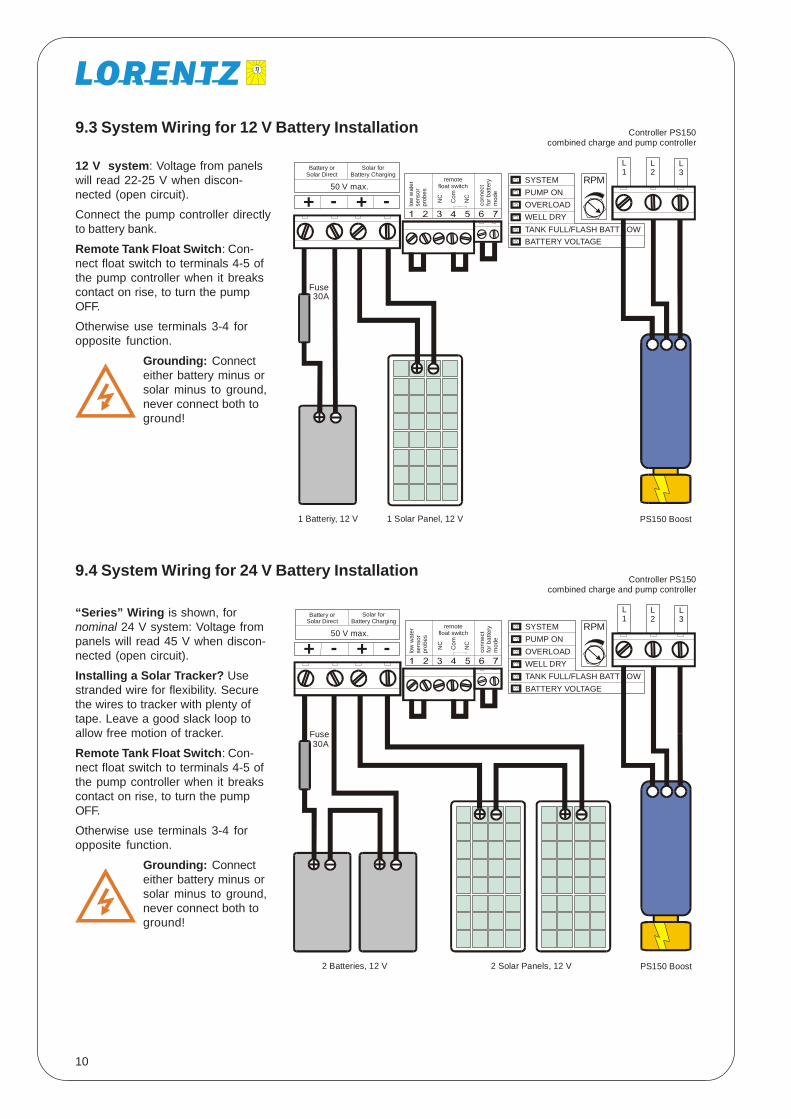
“Series” Wiring is shown, fornominal 24 V system: Voltage frompanels will read 45 V when discon-nected (open circuit).
Installing a Solar Tracker? Usestranded wire for flexibility. Securethe wires to tracker with plenty oftape. Leave a good slack loop toallow free motion of tracker.
Remote Tank Float Switch: Con-nect float switch to terminals 4-5 ofthe pump controller when it breakscontact on rise, to turn the pumpOFF.
Otherwise use terminals 3-4 foropposite function.
Grounding: Connecteither battery minus orsolar minus to ground,never connect both toground!
9.3 System Wiring for 12 V Battery Installation
12 V system: Voltage from panelswill read 22-25 V when discon-nected (open circuit).
Connect the pump controller directlyto battery bank.
Remote Tank Float Switch: Con-nect float switch to terminals 4-5 ofthe pump controller when it breakscontact on rise, to turn the pumpOFF.
Otherwise use terminals 3-4 foropposite function.
Grounding: Connecteither battery minus orsolar minus to ground,never connect both toground!
L1
L2
L3
++ -- low
wat
erse
nsor
prob
es
conn
ect
for b
atte
rym
ode
remotefloat switch
Battery orSolar Direct
50 V max.
Solar forBattery Charging
NC
Com
NC
SYSTEMPUMP ONOVERLOADWELL DRYTANK FULL/FLASH BATT LOWBATTERY VOLTAGE
RPM
2 Batteries, 12 V
Fuse
Controller PS150combined charge and pump controller
2 Solar Panels, 12 V PS150 Boost
L1
L2
L3
++ -- low
wat
erse
nsor
prob
es
conn
ect
for b
atte
rym
ode
remotefloat switch
Battery orSolar Direct
50 V max.
Solar forBattery Charging
NC
Com
NC
SYSTEMPUMP ONOVERLOADWELL DRYTANK FULL/FLASH BATT LOWBATTERY VOLTAGE
RPM
1 Batteriy, 12 V
Fuse
Controller PS150combined charge and pump controller
1 Solar Panel, 12 V PS150 Boost
30A
30A
11
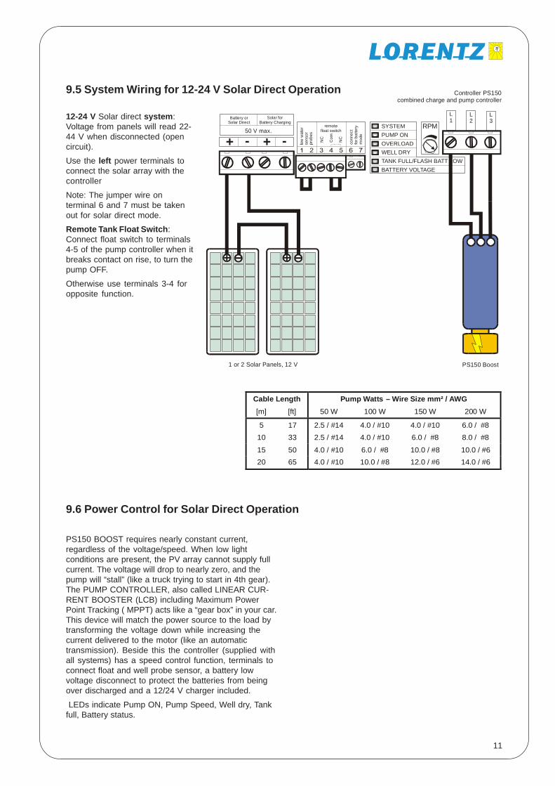
9.6 Power Control for Solar Direct Operation
PS150 BOOST requires nearly constant current,regardless of the voltage/speed. When low lightconditions are present, the PV array cannot supply fullcurrent. The voltage will drop to nearly zero, and thepump will “stall” (like a truck trying to start in 4th gear).The PUMP CONTROLLER, also called LINEAR CUR-RENT BOOSTER (LCB) including Maximum PowerPoint Tracking ( MPPT) acts like a “gear box” in your car.This device will match the power source to the load bytransforming the voltage down while increasing thecurrent delivered to the motor (like an automatictransmission). Beside this the controller (supplied withall systems) has a speed control function, terminals toconnect float and well probe sensor, a battery lowvoltage disconnect to protect the batteries from beingover discharged and a 12/24 V charger included.
LEDs indicate Pump ON, Pump Speed, Well dry, Tankfull, Battery status.
9.5 System Wiring for 12-24 V Solar Direct Operation
L1
L2
L3
++ -- low
wat
erse
nsor
prob
es
conn
ect
for b
atte
rym
ode
remotefloat switch
Battery orSolar Direct
50 V max.
Solar forBattery Charging
NC
Com
NC
SYSTEMPUMP ONOVERLOADWELL DRYTANK FULL/FLASH BATT LOWBATTERY VOLTAGE
RPM
Controller PS150combined charge and pump controller
1 or 2 Solar Panels, 12 V PS150 Boost
12-24 V Solar direct system:Voltage from panels will read 22-44 V when disconnected (opencircuit).
Use the left power terminals toconnect the solar array with thecontroller
Note: The jumper wire onterminal 6 and 7 must be takenout for solar direct mode.
Remote Tank Float Switch:Connect float switch to terminals4-5 of the pump controller when itbreaks contact on rise, to turn thepump OFF.
Otherwise use terminals 3-4 foropposite function.
Cable Length Pump Watts – Wire Size mm² / AWG [m] [ft] 50 W 100 W 150 W 200 W
5 17 2.5 / #14 4.0 / #10 4.0 / #10 6.0 / #8 10 33 2.5 / #14 4.0 / #10 6.0 / #8 8.0 / #8
15 50 4.0 / #10 6.0 / #8 10.0 / #8 10.0 / #6 20 65 4.0 / #10 10.0 / #8 12.0 / #6 14.0 / #6

12
11 PRESSURIZINGSYSTEMS
A PRESSURE TANK IS REQUIRED with a Booster Pumpsystem. PRESSURE TANKS are available from localwater supply dealers. Use the largest tank you arewilling to buy. 150l/40 US_gal. size is typical; it allowsyou about 45l/12 US-gal. of water between pumpcycles. Those 45l/12 US-gal. may be drawn at a higherflow rate than the pump produces. A large pressuretank will minimize on/off cycling of the pump. In a typicalhousehold of more than four people, a tank of at least230l/60 US-gal. is recommended. The bigger thebetter! More than one tank may be connected. Theyneed not be the same size.
A PRE CHARGED “CAPTIVE AIR” TANK is recom-mended. Cheaper “galvanized tanks” require periodicrecharging, store less water between cycles, and don’tlast as long. PROPER PRE CHARGE IS ESSENTIAL toproper operation. Follow the instructions that come withyour pressure tank. (With pressure discharged from thetank, adjust pre--charge to about 0.2 bar/2 PSI belowcut in pressure.) This is very important.
PRESSURE SWITCH ADJUSTMENT: Switch settingsdetermine the pressure range of your system. Toconserve energy, set the pressure as LOW as feasible.This will also prevent the motor from overheating if yourun it for long periods sprinkling, for example. Lowpressure (even 1-1.5 bar/15-20 PSI) may deliverexcellent water flow IF your plumbing and hoses aresized larger than minimum. lf not yet plumbed, use atleast one size larger pipe than conventional, and avoidrestrictive connections such as 3/8" tubing often usedto feed sinks.
Adjustment: Start with the standard setting (usually 2.0/3.5 bar respectively 30/50 PSI). Reduce the pressureaccording to your requirements, if you wish. It is wise tomeasure the current used by your pump (with an ampmeter in series with the line, your system metering).Current draw will rise in direct proportion to outletpressure. Pressure should NOT be set beyond 4.5 bar/
PrimingPlug
InlineFilter
PS150 BOOST
Pressure Tank
CheckValve
PressureReliefValve
HoseBib
PressureSwitch
To HousePlumbing
10 WATER LEVEL ANDFLOW CONTROL
FLOAT SWITCHES/WATER LEVEL SENSORS: Theseare devices that sense high or low water level andswitch your pump on and off . FLOAT CONTROL INWATER SOURCE may be used if dropping water levelis causing dry run or excessive suction (noise due tocavitation).
In case the pump sucks water from a shallow well,connect our well probe sensor (article #1658) toterminal 1-2 in the pump controller. There is a 20 mintime delay to restart the pump once the well was dry.The well dry LED will light up and once the pump hasrestarted it will slowly flash to indicate that the well wasdry before.
FLOAT CONTROL IN STORAGE TANK may be used toturn pump off when tank fills. This eliminates tankoverflow and reduces pump wear and filter changing.
Small wire buried from tank/float switch to pumpcontroller. ( Connect to Terminal 4-5 for NC type switch),there is no time delay for restarting.
Or a Float valve in tank restricts flow. Pressure buildsup and actuates pressure switch at pump. Smallcaptive air pressure tank is necessary at pump toprevent “switch chatter”.
Contact your dealer or the factory for further advice.FLOW RESTRICTION MUST NOT BE USED as a methodto reduce your pump’s flow rate. It may result in exces-sive pressure build up and current draw. Use thecontrollers RPM knop to adjust the flow rate.
OverflowPipe
Fee PipefromWell Pump Foot Valve Suction
Pipe
Air Vent andDipstick Access
MaintenanceAccess
Float Switch
PS150 BOOST PumpInstallation: Fromcistern or storage tank,where pump must behigher than source.
13
12 MAINTENANCEINTERNAL INTAKE SCREEN: The pumps of Series 1300have an internal metal intake screen. Its purpose is tocatch solids accidentally introduced during installationor filter servicing, dirt stuck inside your intake pipebefore installation, or mineral deposits that mayaccumulate and flake off of the intake piping. 1300SERIES “PS150 BOOST” has an angled extension witha large brass nut on the end. Remove the nut to inspectand empty screen.
EXTERNAL FILTRATION IS STILL REQUIRED! lf younotice signs of intake blockage, inspect your screen. lfsolids keep accumulating, improve your filtration. SeePage 6 for details about filters and cartridges.
PUMP HEAD: Except for the internal screen, your pumphead is maintenance free. DO NOT remove its frontplate or otherwise tamper with it unless you are
WARNING: INSTALL THE PRESSURERELIEF VALVE INCLUDED WITH YOURPUMP! Some PS150 BOOST Pumps forcity water pressure systems are suppliedwith a 6 bar / 85 PSI Pressure Relief Valve
as a safety feature. lf your pressure switch fails,EXCESSIVE PRESSURE may cause your tank of pipingto burst and flood your home.
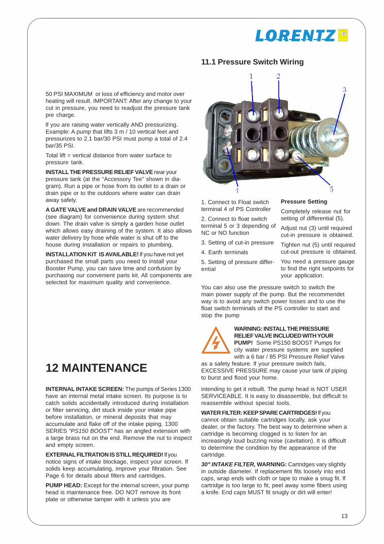
11.1 Pressure Switch Wiring
intending to get it rebuilt. The pump head is NOT USERSERVICEABLE. It is easy to disassemble, but difficult toreassemble without special tools.
WATER FILTER: KEEP SPARE CARTRIDGES! lf youcannot obtain suitable cartridges locally, ask yourdealer, or the factory. The best way to determine when acartridge is becoming clogged is to listen for anincreasingly loud buzzing noise (cavitation). It is difficultto determine the condition by the appearance of thecartridge.
30" INTAKE FILTER, WARNING: Cartridges vary slightlyin outside diameter. If replacement fits loosely into endcaps, wrap ends with cloth or tape to make a snug fit. lfcartridge is too large to fit, peel away some fibers usinga knife. End caps MUST fit snugly or dirt will enter!
1. Connect to Float switchterminal 4 of PS Controller
2. Connect to float switchterminal 5 or 3 depending ofNC or NO function
3. Setting of cut-in pressure
4. Earth terminals
5. Setting of pressure differ-ential
50 PSI MAXIMUM or loss of efficiency and motor overheating will result. IMPORTANT: After any change to yourcut in pressure, you need to readjust the pressure tankpre charge.
lf you are raising water vertically AND pressurizing.Example: A pump that lifts 3 m / 10 vertical feet andpressurizes to 2.1 bar/30 PSI must pump a total of 2.4bar/35 PSI.
Total lift = vertical distance from water surface topressure tank.
INSTALL THE PRESSURE RELIEF VALVE near yourpressure tank (at the “Accessory Tee” shown in dia-gram). Run a pipe or hose from its outlet to a drain ordrain pipe or to the outdoors where water can drainaway safely.
A GATE VALVE and DRAIN VALVE are recommended(see diagram) for convenience during system shutdown. The drain valve is simply a garden hose outletwhich allows easy draining of the system. It also allowswater delivery by hose while water is shut off to thehouse during installation or repairs to plumbing.
INSTALLATION KIT IS AVAILABLE! lf you have not yetpurchased the small parts you need to install yourBooster Pump, you can save time and confusion bypurchasing our convenient parts kit. All components areselected for maximum quality and convenience.
Pressure SettingCompletely release nut forsetting of differential (5).
Adjust nut (3) until requiredcut-in pressure is obtained.
Tighten nut (5) until requiredcut-out pressure is obtained.
You need a pressure gaugeto find the right setpoints foryour application.
You can also use the pressure switch to switch themain power supply of the pump. But the recommendetway is to avoid any switch power losses and to use thefloat switch terminals of the PS controller to start andstop the pump

14
13 TROUBLESHOOTING
PUMP WILL NOT FIT INTO YOUR 5" OR 6" DRILLEDWELL CASING: Special elbow fittings are required.Contact dealer or factory.
PUMP DOESN‘T TURN ON/NO POWER: (1) CHECKFUSE or BREAKER and any control or wiring devices inline.
PUMP SPINS BUT DOESN‘T PUMP WATER: (1) CHECKDIRECTION of rotation. If not clockwise (viewed frombrass front end) reverse any of the three motor phases.DO NOT CHANGE THE DC INPUT POLARITY! (2)CHECK PRIME: Open priming plug or valve (seeinstructions). Pour water in. LOSS OF PRIME/INTAKEPIPE LEAKAGE: CHECK ALL FITTINGS - a pinhole leakin suction pipe will cause loss. FOOT VALVE may leak.Inspect, pressure test, clean or replace. Debris may bestuck in foot valve causing leak ff not protected by finescreen or intake filter. REGARDING POLYTHYLENEPIPE FITTINGS: lf pipe does not stretch tightly overfittings, it may leak. Gently heat with torch or hot waterand retighten hose clamp WITH WRENCH. Replacestripped clamps. Use ALL STAINLESS clamps.
NOISY PUMP:NOISE = CAVITATION = RAPID PUMP WEARFIX THE PROBLEM!STEADY SOUND Indicates EXCESSIVE SUCTION dueto any combination of (1) HIGH SUCTION LIFT mountpump as low as possible, (2) UNDERSIZED SUCTIONPIPE, (3) CLOGGED FILTER NOTE: Fiber filtercartridges may be clogged and LOOK CLEAN (fine siltis hidden within the fibers). (4) CLOGGED INTERNALINTAKE SCREEN. See next two entries. (5) SOFT,FLEXIBLE HOSE used on intake line may be crushedor kinked by suction -replace with more rigid pipematerial.
UNSTEADY BUZZING SOUND Indicates LEAK INSUCTION LINE allowing AIR to enter. (1) Check forbubbles in inline (transparent) filter or air in outletwater. (2) See LOSS OF PRIME in above entry. (3) lf youhave INLINE FILTER with red Pressure Relief Valve (redbutton) on top, and it is mounted several feet abovewater source, air may be drawing in around the valve,SEAL AROUND THE VALVE with silicone sealant orepoxy glue OR unscrew the red button and replace itwith a nut, tightened. (4) lf no source of air leakage ispresent, water may have high concentration of DIS-SOLVED GASSES which release as bubbles in suctionpipe. Reduce suction lift if possible. Install air chamberin intake line, with valve on top. Pour water in to replaceair when problem reappears. (5) Turn filter to a horizon-tal position. This allows bubbles to get out of the way offlow. Do NOT turn it upside down, or dirt may fall inwhen filter is changed.
NOISE AND VIBRATION IN PIPES (pressure gaugevibrates wildly): One of four vanes in the pump isbroken. Pump head must be rebuilt See Rebuild/Exchange Service. (There should be almost no vibra-tion of pressure gauge needle.)
FILTER CLOGS FREQUENTLY: (1) INTAKE TOO CLOSE tobottom of well, stream, tank etc. Raise it as high asfeasible to reduce intake of dirt. (2) IMPROVE DEVEL-OPMENT of spring channel water into a settling tank,clean tank periodically. (3) Install a larger filter, or plumbtwo filters parallel to each other.
CLOGGED INTAKE SCREEN: Safety screen is located atthe pump intake. Remove large nut (1300 series) toinspect and clean screen. (1) IF YOU DON’T HAVE ACARTRIDGE TYPE FILTER, INSTALL ONE NOW! (2) Ifscreen is clogged with fibers from filter cartridge, usehigher quality cartridges. (3) If screen is clogged withrust deposits, replace iron pipe or fittings with plastic,copper or brass. (4) If mineral or corrosion deposits areclogging screen, install filter as close as possible topump intake. Ask local water professionals what type ofpipe is least susceptible to mineral accumulation andcorrosion in your area.
FILTER IS CLOGGED AND YOU DON’T HAVE REPLACE-MENT: (1) IN LINE FILTER: Purchase common “Rustand Sediment” fiber wound cartridge at local hardwarestore or pump/well supplier. (2) 30" INTAKE FILTER:Obtain spares from your dealer, factory or industrialsuppliers. In emergency, purchase 3 ordinary 1 10' fiberfilters (not paper) from local source. Glue them end toend with epoxy and install. (3) TRY BACK WASHINGfilter by blasting it with pressure from the inside. For 30"intake filter, remove check valve and attach garden hoseadapter. Back washing is effective on coarse, sandymaterial but is NOT effective with clay, rust, very fine orsticky deposits.
PURCHASE SPARE FILTERS. NEVER RUN PUMPWITHOUT A FILTER!LOW FLOW RATE † PUMP TURNS FAST, DRAWS LOWCURRENT: Pump is worn out from dirt, rust or otherabrasive particles in water, or from cavitation, fromrunning dry, or just from age. REPLACE PUMP HEAD.
BOOSTER PUMP TAKES LONG TIME TO REACH CUTOFF PRESSURE: (1) If pump spins fast, see above entry.(2) If pump rotation slows way down as pressurebuilds, wire is too small. Consult low voltage wire sizechart or ask your dealer for correct wire size.
LOW FLOW RATE - PUMP TURNS SLOW, DRAWS HIGHCURRENT (may run hot, may blow fuses): Pump is hardto turn due to: (1) EXCESSIVE VERTICAL LIFT, beyondsystem’s capacity: Trade pump head for lower volumemodel, or increase size of solar array if it will notoverpower the motor -see Specifications Chart. (2)MINERAL DEPOSITS: Turn shaft with two fingers. Willbe hard to turn. Use vinegar, or whatever solution worksto dissolve the mineral deposits in your plumbing.Remove pipes from pump and allow solution tocirculate through pump by turning it backwards. If thisdoesn’t work, or if pump has been damaged, replace orrebuild.
15
Your pump is warranted to be free from defects inmaterial and workmanship for one (1) YEAR from dateof purchase.
Failure to provide correct installation, operation, or carefor the product, in accordance with instructions, will voidthe warranty.
Product liability, except where mandated by law, islimited to repair or replacement, at the manufacturer’sdiscretion. No specific claim of merchantability shall beassumed or implied beyond what is printed on themanufacturer’s printed literature. No liability shall existfrom circumstances arising from the inability to use theproduct, or its inappropriateness for any specificpurpose. It is the user’s responsibility to determine thesuitability of the product for any particular use.
Pump Rotor / Stator / Vanes of PS150 BOOST Motor /Pump are considered to be normally wearing parts,and are not covered under warranty. Warranty does notcover damage due to sand or abrasive silt in the water,mishandling or other abusive conditions, lightning orother acts of nature.
Warranty of pump controllers does not cover damagedue to: mishandling or abuse; failure to protect fromweather exposure; failure to protect from overheatingdue to sun exposure; failure to seal out insects,spiders or rodents; lightning, flood or other acts ofnature.
In all cases, it shall be the responsibility of the cus-tomer to insure a safe installation in compliance withlocal, state and national electrical codes.
14 WARRANTY
BOOSTER PUMP CYCLES ON AND OFF EVERY FEWSECONDS (PRESSURIZING SYSTEM): PRESSURETANK MUST be used with system. Pre charge tank viaair fitting to 0.15 bar/2 PSI less than cut in pressure.Turn power off and release water pressure beforesetting pre charge. Modern “captive air” tank will notneed pre charging again. GALVANIZED TANK (withoutair bladder) MUST BE RECHARGED with air aboutonce per year as air dissolves into water. Use tirepump or compressor.
BOOSTER PUMP TURNS ON PERIODICALLY WHEN NOWATER IS BEING USED. (1) Water is leaking some-where after the check valve (check valve must beinstalled at pump outlet). (2) Check valve leaks inter-nally. Foot valve, if present, also leaks.
PUMP RUNS TOO SLOW OR STALLS IN LOW LIGHT(Array Direct, Non Battery System): (1) Solar array orwire is undersized. (2) RPM speed control pot is turnedto low RPM, turn full clock wise. Contact dealer orfactory.
PUMP WON’T TURN, shaft (turn the fan) can’t be turnedby hand. Should blow fuse or breaker: (1) After a periodof disuse or storage, parts may lock up. Grab shaft (fanside of motor) lightly with pliers and try turning itbackwards. (2) Debris jammed in pump. Disconnectplumbing, pour water into outlet, and run pump inREVERSE . Watch for debris exiting inlet. Checkperformance - damage is likely. (3) See “Pump Frozen”.
PUMP JAMS, MAKES CRUNCHING NOISES, blackmaterial in outlet: Internal parts are broken, either bydebris in pump, severe freezing, external shock or justbad luck. See “Rebuild/Exchange Service”.
WATER DAMAGE: MOTOR SUBMERGED OR DRIPPEDON. Inspect motor. If in very poor condition, motor maybe beyond repair. Contact factory. If motor was not runwet for very long, it may need only new bearings.CORRECT THE CAUSE of damage. If your water levelis too unstable, contact your dealer or factory about asubmersible pump.
PUMP FROZEN BY LOW TEMPERATURE: (overload LEDis ON) Allow it to thaw. Observe/test performance. Ifdamaged, replace or rebuild. Check all plumbing fordamage and leaks and protect from future freezing.
16
Copyright © 2004, 2005 by BERNT LORENTZ KG, all rights reserved.
Bernt Lorentz GmbH & Co. KGHeidekoppel 16D-24558 Henstedt-UlzburgGermany
Tel. ++49.4193.7548-0Fax ++49.4193.7548-29