psa qb 15-16 with answer.docx
TRANSCRIPT

8/18/2019 PSA qb 15-16 with answer.docx
http://slidepdf.com/reader/full/psa-qb-15-16-with-answerdocx 1/75
EE6501 Power system Analysis Department of EEE 2015-2016
UNIT – I INTRODUCTIONPART – A
1. What is the advantage of per unit method over perentage method!The per unit method has an advantage over the percent method because the product of two quantitiesexpressed in per unit is expressed in per unit itself, but the product of two quantities expressed in percent must be divided by 100 to obtain result in percent.
". What is the need of #ase va$ues!The components or various sections of power system may operate of different voltage and power levels. It will be convenient for analysis of power system if the voltage, power, current and impedanceratings of components of power system are expressed with reference to a common value called basevalue. Hence for analysis purpose, a base value is chosen for voltage, power, current and impedanceratings of the components are expressed as a percent of per unit of the base value.
%. Wh& the va$ue of vo$tage and %'phase ()A are diret$& used for per unit a$u$ation in %'phases&stem!The perunit value of a linetoneutral !"#$% voltage on the linetoneutral voltage base value !" b,#$% isequal to the per unit value of the linetoline voltage!" ##% at the same point on the linetoline voltage!" b##% if the system is !"##% at the same point on the linetoline voltage base!" b##%if the system is
balanced.V
ln
V bL− N =
V ¿V bL− L
.The per unit value of a &phase '"( on the &phase !'"(% base is
identical to the per unit value of '"( per phase on the '"( per phase base.i.e.,
phase per'"()ase
phase per'"(
'"( base phase&
&phase'"(=
.Therefore in &phase systems the line value of voltage and & phase '"( are directly used for unit calculations.
*. What is sing$e $ine diagram!( single line diagram is diagrammatic representation of power system in which the components arerepresented by their symbols and the inter connection between them are shown by a single straight line!even though the system is &phase system%. The ratings and the impedances of the components arealso mar*ed on the single line diagram.
+. What are the omponents of po,er s&stem!The components of power system are generators, power transformers, motors, transmission lines,
substation transformers, distribution transformers and loads.-. Define per unit va$ue.The per unit value of any quantity is defined as the ratio of the actual value of the quantity to the basevalue expressed as a decimal. The base value is an arbitrary chosen value of the quantity.
Perunit value= Actualvalue
Basevalue. Write the e/uation for onverting the p.u. impedane e0pressed in one #ase to another!
Z pu , New=Z pu ,old X [ KV b,old KV b,new ]2
X [ MVAb,new
MVAb,old ]
. What are the advantages of per unit omputation!i% +anufactures usually specify the impedance of a device or machine in per unit on the base of the
name plate rating .ii% The p.u."alues of widely different rating machines lie within a narrow range,even though the ohmic values has a very large range.iii% The p.u. Impedance of circuit elementconnected by transformers expressed on a power base will be same is if it is referred to either side of atransformer.iv% The p.u. impedance of a & transformer is independent of the type of winding connection! or -%ϕ
2. 3o, the $oads are represented in reatane or impedane diagram!The resistive and reactive loads can be represented by any one of the following representation.
i% onstant power representation, #oad power jQ P S +=
ii% onstant current representation, #oad urrent I =√ P
2+Q2
|V | ∠δ −θ
St. Joseph’s Collee of Enineerin!St. Joseph’s "nstit#te of $e%hnoloy 1 "S& '001(200)

8/18/2019 PSA qb 15-16 with answer.docx
http://slidepdf.com/reader/full/psa-qb-15-16-with-answerdocx 2/75
EE6501 Power system Analysis Department of EEE 2015-2016
iii% onstant impedance representation. #oad impedance Z =V
2
P− Q14. A generator rated at %45)A6 11() has a reatane of "47 a$u$ate its p.u reatane for a #ase
of +4 5)A and 14().
X pu , New= X pu ,old X [ KV b,old KV b,new ]2
X [ MVAb,new
MVAb,old ] /0. x !1110%x !20&0% / 0.30&pu
11. The #ase () and #ase 5)A of a %'phase transmission $ine is %%() and 14 5)A respetive$&a$u$ate the #ase urrent and #ase impedane!
)ase current,
( )142(
&&&
100010
'"&
1000!+"(%
'"&
'"(
b
b
b
b b =
×
×=
×== I
)ase impedance, Z b=( KV b )2
MVAb
=33
2
10=¿ 105.67
1". What is impedane diagram!The impedance diagram is the equivalent circuit of power system in which the various components of power system are represented by their approximate or simplified equivalent circuits. The impedance diagram is used for load flow studies.
1%. What is reatane diagram!The reactance diagram is the simplified equivalent circuit of power system in which the variouscomponents are represented by their reactance. The reactance diagram can be obtained from impedancediagram if all the resistive components are neglected. The reactance diagram is used for faultcalculations.1*. What are the appro0imations made in reatane diagram!i% The neutral reactance are neglected ii% 8hunt branches in the equivalent circuits of transformers areneglected iii% The resistance are neglected. iv% (ll static loads and induction motors are neglected. v% thecapacitance of the transmission lines are neglected1+. 8ive e/uations for transforming #ase () on 9) side to 3) side of transformer.
Base KV on!" side=Base KV on<sideX !" volta#e ratin#
¿volta#e ratin#
Base KV on<side=Base KV on!" side X ¿volta#e ratin# !" volta#e ratin#
1-. What is #us!The meeting point of various components in a power system is called as bus. The bus is a conductor madeof copper or aluminum having negligible resistance. The buses are considered as points of constantvoltage in a power system.1. What are the disadvantages of per unit s&stem!The disadvantages of per unit system are some equations that hold in the unscaled case are modified whenscaled into per unit factors such as9& and & are removed or added in this method. :quivalent circuits of the components are modified ma*ing them somewhat more abstract. 8ometimes these shifts that areclearly present in the unscaled circuit vanish in per unit circuit.1. What is :Tap hanging; transformer! <tate its t&pes.
The transformer is wounded with tapping on either primary or secondary winding to ad;ust the voltage.The device used to give the constant output voltage is called tap changing transformer. The types arei%<$load automatic tap changer ii%<== load tap changer.12. What is off nomina$ transformation ratio!>hen the voltage !or% turns ration of a transformer is not used to decide the ratio of base *", its voltage!or% turns ration is called offnominal ratio. ?sually the voltage ratio of regulation transformer will beoffnominal ratio.
"4.Write the four ,a&s of adding an impedane to an e0isting s&stem so as to modif& =>us matri0.1. (dding a branch of impedance @ b from a new bus p to the reference bus. . (dding a branch of impedance @ b from a new bus p to an existing bus. &. (dding a branch of impedance @ b from an existing bus q to the reference bus. 3. (dding a branch of impedance @ b between two existing buses p and q.
St. Joseph’s Collee of Enineerin!St. Joseph’s "nstit#te of $e%hnoloy 2 "S& '001(200)

8/18/2019 PSA qb 15-16 with answer.docx
http://slidepdf.com/reader/full/psa-qb-15-16-with-answerdocx 3/75
EE6501 Power system Analysis Department of EEE 2015-2016
"1.What are the methods avai$a#$e for forming #us impedane matri0!!i% =orm the bus impedance matrix and then ta*e its inverse to get bus impedance matrix.!ii% Airectly form the bus impedance matrix from the reactance diagram. This method utiliBes thetechniques of modifications of existing bus impedance matrix due to addition of new bus.
"". What are the representation of $oads! ?5a& "41*@i% onstant power representation ii% onstant current representation iii% onstant impedancerepresentation"%. What is the purpose of providing third ,inding ?tertiar&@ in a transformer!i% Third winding may be used for interconnecting three transmission line at different voltages.ii% It is sometimes used for other purposes such as connecting shunt capacitors !or% suppression of thirdharmonics voltages.iii% To get supply power for substation internal purposes. iv% Tertiary winding canserve the purpose of measuring voltage of an H" testing transformer."*. What are the advantages of per unit s&stem! ?5a& "411@a% calculations are simple. b% It will be convenient for analysis of power system if the voltage, power,current and impedance ratings of components of power system are expressed with reference to a commonvalue called base value"+. Dra, a simp$e per'phase mode$ for a &$indria$ rotor s&nhronous mahine. ?5a& "411@
"-. What are the omponents of po,er s&stem! ?5a& "41"@Cenerator, Transformer, Transmission lines and #oads". If the reatane in ohms is 1+6 find the p.u va$ue for a #ase of 1+()A and 14()! ?5a& "41"@
Z ( pu )=Z $MVA b KV b
2 =15$15
102 =2.25
". Dra, the e/uiva$ent iruit of a three ,inding transformer. ?Nov "41"@?5a& "41%@
"2. What is meant #& perentage reatane! ?5a& "41%@
Dercentage reactance of a transformer !or in general, a circuit% is the percentage of phase voltage dropwhen full load current flows through it, i.e EF/ !IF"%G100.%4. What are the funtions of 5odern po,er s&stem! ?Nov "41%@The modern power system is a networ* of electric components which is used to supply !generatingstation%, transmit !transmission system% and distribute !distribution system% the electrical power.%1. Name the diagona$ and off diagona$ e$ements of #us impedane matri0. ?Nov "41%@The diagonal elements are called as driving point impedances and off diagonal elements are called astransfer impedances.%". Dra, the impedane diagram for the given sing$e $ine representation of the po,er s&stem.
St. Joseph’s Collee of Enineerin!St. Joseph’s "nstit#te of $e%hnoloy * "S& '001(200)

8/18/2019 PSA qb 15-16 with answer.docx
http://slidepdf.com/reader/full/psa-qb-15-16-with-answerdocx 4/75
EE6501 Power system Analysis Department of EEE 2015-2016
?5a& "41*@Impedane Diagram
%%. What are the main divisions of Po,er <&stem! ?Nov "41*@The main divisions of power systems are i% Ceneration ii% Transmission iii%Aistribution.%*. What is the need for per unit va$ue! ?Nov "41*@In a power system different power equipment with different voltage and power levels are connectedtogether through various step up or step down transformers. However the presence of various voltage and power levels causes problem in finding out the currents !or voltages% at different points in the networ*. Toall eviate this problem, all the system quantities are converted into a uniform normaliBed platform. Theunits of these normaliBed values are per unit
PART – >1. 0p$ain modern po,er s&stem in detai$ and dra, #asi omponents of po,er s&stem.
?Nov "41*@
St. Joseph’s Collee of Enineerin!St. Joseph’s "nstit#te of $e%hnoloy + "S& '001(200)

8/18/2019 PSA qb 15-16 with answer.docx
http://slidepdf.com/reader/full/psa-qb-15-16-with-answerdocx 5/75
EE6501 Power system Analysis Department of EEE 2015-2016
". The three phase po,er and $ine'$ine ratings of the e$etri po,er s&stem are given#e$o,B81B-45)A6"4()627ET1B+45)A6"4F"44()6147ET"B+45)A6"44F"4()6147E5B *%."5)A6 1()6 7E 9ineB "44()6 =1"4GH"44 ohm. Dra, an impedane diagramsho,ing a$$ impedanes in per'unit on a 144'5)A #ase. Choose "4() as the vo$tage #ase forgenerator.
<o$ution
Z pu , New=Z pu ,old X [ KV b,old KV b,new ]2
X [ MVAb,new
MVAb,old ]
The per unit impedane of8enerator 8B H4.1+p.u6Transformer T1BH4." p.u6Transformer T"BH4." p.u65otor 5BH4.1- p.uor transmission $ineB=p.uB 4.%G4.+H p.u
St. Joseph’s Collee of Enineerin!St. Joseph’s "nstit#te of $e%hnoloy 5 "S& '001(200)

8/18/2019 PSA qb 15-16 with answer.docx
http://slidepdf.com/reader/full/psa-qb-15-16-with-answerdocx 6/75
EE6501 Power system Analysis Department of EEE 2015-2016
&. ( 0+"(, 11'" three phase synchronous generator has a sub transient reactance of 10E. It isconnected through three identical single phase ∆ connected transformer 2000'"( 1114.0'"with a reactance of 12E to a high voltage transmission line having a total series reactance of 50ohm.(t the end of HT transmission line, three identical single phase starstar connected transformer of 2000'"(, 14.01.40'" with a reactance of 0E. The load is drawing 12+"(, at 1.2 '" and0.6p.f lagging. Araw single line diagrams of the networ* choose a common base of 12+"( and
1.2'" and determine the reactance diagram.<o$ution
X pu , New= X pu ,old∗[ KV b,old KV b,new ]2
∗[ MVAb,new
MVAb,old ]
The per unit reatane of8enerator 8B H4."%"% p.uTransformer T1BH4.*-* p.u6Transformer T"BH4.-12+ p.u69oad B4.2G4.*%-H p.u9oad CurrentB 1J'%-.K p.uor transmission $ineB=p.uB 4.4-H p.u
3. >rite short notes on the following i%perphase analysis of a generator ii%perphase analysis of &windig transformerper'phase ana$&sis of a generator
per'phase ana$&sis of %',indig transformer
St. Joseph’s Collee of Enineerin!St. Joseph’s "nstit#te of $e%hnoloy 6 "S& '001(200)

8/18/2019 PSA qb 15-16 with answer.docx
http://slidepdf.com/reader/full/psa-qb-15-16-with-answerdocx 7/75
EE6501 Power system Analysis Department of EEE 2015-2016
2. >ith the help of single line diagram ,explain the basic components of a power system.?5a& "411@
. i%>rite detailed notes about the per phase model of a three phase transformer.?5a& "411@
ii% Araw an impedance diagram for the electric power system shown in figure, showing all theimpedances in per unit on a 100 +"( base .hoose 0 '" as the voltage base for generator. The& power and line rating are given below.ϕ C160+"(,0'",F/6E.JTr150+"(,000'",F/1ETr 50+"(, 000'",F/0EJC60+"(,15'",F/6EJ#ine00'",F/107,#oad00 '",8/35+>K;3+"(L.
<o$ution
Z pu , New=Z pu ,old X
[ KV b,old
KV b,new
]
2
X
[ MVAb,new
MVAb,old
]The per unit impedane of8enerator 81B H4.1 p.u8enerator 8"B H4.41 p.uTransformer T1BH4." p.u6Transformer T"BH4."+ p.u69oad B4.+GH p.uor transmission $ineB=p.uB 4.%H p.u
St. Joseph’s Collee of Enineerin!St. Joseph’s "nstit#te of $e%hnoloy , "S& '001(200)

8/18/2019 PSA qb 15-16 with answer.docx
http://slidepdf.com/reader/full/psa-qb-15-16-with-answerdocx 8/75
EE6501 Power system Analysis Department of EEE 2015-2016
4. i. >hat are the advantages of per unit computations.?5a&6 "41"@
ii. Araw the reactance diagram for the power system shown in figure. $eglect resistance and use a baseof 100 +"(, 0 '" in 20M line. The ratings of the generator, motor and transformer aregivenasCenerator 30 +"(, 2 '", FN /0EJ 8ynchronous motor 20 +"(, 11'", FN/&0E
Transformer 30 +"(, &&0'", F/12E J O Transformer &0+"(, 110'", !O%,F/12E
<o$ution
X pu , New= X pu ,old∗[ KV b,old KV b,new ]2
∗[ MVAb,new
MVAb,old ]
The per unit reatane of8enerator 8B H4.%p.uTransformer T1BH4.%+ p.u6Transformer T"BH4.+ p.u65otor 5 BH4.-p.uor transmission $ineB=p.uB 4.14%H p.u
St. Joseph’s Collee of Enineerin!St. Joseph’s "nstit#te of $e%hnoloy ) "S& '001(200)

8/18/2019 PSA qb 15-16 with answer.docx
http://slidepdf.com/reader/full/psa-qb-15-16-with-answerdocx 9/75
EE6501 Power system Analysis Department of EEE 2015-2016
5. =ind the bus impedance matrix for the 3 P bus system shown in figure. onsider bus P 3 as thereference bus. ?5a&6 "41"@
<o$utionB
Z inew=Z i
old−Z i (n+1)Z (n+1)
Z (n+1 )(n+1)
=>us
[ 0.626 0.373 0.5 0.373 0.626 0.5
0.5 0.5 ]6. The oneline diagram of a power system is shown in figure. The threephase power and line ratings are
given below. !1& +ar*s% ?Nov6 "41"@C 50 +"( '" F/6E Tr1 20 +"( 0 '" F/10E
Tr1 30 +"( 0 '" F/.0E Tr&, Tr3 30 +"( 110 '" F/.3E#ine 1 0 '" F/11M #ine 110 '" F/ 3.&2M
+ 5.52 +"( 0 '" F/.2E #oad 10 +"(L, 3'" -onnected apacitor.Araw an impedance diagram showing all impedance in per Punit on a 100 +"( base. hoose '"as the voltage base for generator.
<o$ution
St. Joseph’s Collee of Enineerin!St. Joseph’s "nstit#te of $e%hnoloy ' "S& '001(200)

8/18/2019 PSA qb 15-16 with answer.docx
http://slidepdf.com/reader/full/psa-qb-15-16-with-answerdocx 10/75
EE6501 Power system Analysis Department of EEE 2015-2016
Z pu , New=Z pu ,old X [ KV b,old KV b,new ]2
X [ MVAb,new
MVAb,old ]
The per unit impedane of8enerator 8B H4.11"+ p.uTransformer T1BH4." p.u6Transformer T"BH4.1+ p.u6Transformer T%BH4.1- p.u6Transformer T*BH4.1- p.u69ine 1 B4."+H p.u 9ine "B4.%+H p.u5otor 5B4."Hp.u
!ii% 8tate the applications of bus admittance matrix !& +ar*s%Represents the admittane re$ationships #et,een nodes6 ,hih then determine the vo$tages6 urrents andpo,er f$o,s in the s&stem. 10. =orm the bus impedance matrix for the networ* shown by building algorithms.?Nov"41"@?5a& "41%@
<o$utionB
Z inew=Z i
old−Z i (n+1)Z (n+1)
Z (n+1 )(n+1)
=>us [ 0.12 0.095 0
0.095 0 0
0 0 0.153]
11.=or the system shown in figure obtain the impedance diagram.Ta*e a base of 100 +"( and 10 '" in
the transmission line. ?5a& "41%@
<o$ution
Z pu , New=Z pu ,old X [ KV b,old KV b,new ]2
X [ MVAb,new
MVAb,old ]
The per unit impedane of
St. Joseph’s Collee of Enineerin!St. Joseph’s "nstit#te of $e%hnoloy 10 "S& '001(200)

8/18/2019 PSA qb 15-16 with answer.docx
http://slidepdf.com/reader/full/psa-qb-15-16-with-answerdocx 11/75
EE6501 Power system Analysis Department of EEE 2015-2016
8enerator 8B H p.uTransformer TBH4.* p.u69ine B4."4-H p.u 9oadB1.4% p.u
1 . hy is per #nit system #se in power system analysis/ An list its aantaes. ay 201*3
St. Joseph’s Collee of Enineerin!St. Joseph’s "nstit#te of $e%hnoloy 11 "S& '001(200)

8/18/2019 PSA qb 15-16 with answer.docx
http://slidepdf.com/reader/full/psa-qb-15-16-with-answerdocx 12/75
EE6501 Power system Analysis Department of EEE 2015-2016
St. Joseph’s Collee of Enineerin!St. Joseph’s "nstit#te of $e%hnoloy 12 "S& '001(200)

8/18/2019 PSA qb 15-16 with answer.docx
http://slidepdf.com/reader/full/psa-qb-15-16-with-answerdocx 13/75
EE6501 Power system Analysis Department of EEE 2015-2016
1&. ( 60 +"( 11 '" & phase generator has a reactance of 2E.The generator supplies two motorsthrough transformer and transmission line as shown in figure. The transformer T 1 is a &phasetransformer,100 +"(, 101& '", E reactance. The transformer T is composed of & single phaseunits each rated, &0 +"(J 10 '", with 2E reactance. The connection of T 1Q T are shown .Themotors are rated at 20 +"( and 30 +"( both 10 '" and 0E reactance. Ta*ing the generator ratingas base draw reactance diagram and indicate the reactance in per unit. The reactance of line is 100 7.?Nov "41%@
<o$ution
Z pu , New=Z pu ,old X [ KV b,old KV b,new ]2
X [ MVAb,new
MVAb,old ]
The per unit reatane of8enerator 8B H 4."+ p.uTransformer T1BH4.4** p.u69ine B4.*"-H p.uTransformer T"BH4.4%42p.u5otor 51BH4.4-p.u5otor 5"BH4.4++p.u
13. !i% Aetermine )usfor the &bus system shown in figure. The line series impedance as follows.#ine !bus to bus% Impedance!pu%1 0.0 K ;0.151& 0.0& K ;0.06
St. Joseph’s Collee of Enineerin!St. Joseph’s "nstit#te of $e%hnoloy 1* "S& '001(200)

8/18/2019 PSA qb 15-16 with answer.docx
http://slidepdf.com/reader/full/psa-qb-15-16-with-answerdocx 14/75
EE6501 Power system Analysis Department of EEE 2015-2016
& 0.05 K ;0.3 $eglect the 8hunt capacitance of the lines
<o$utionB
L>us [ 5−15 −1.67+5 −3.33+10
−1.67+5 2.92−8.75 −1.25+3.75
−3.33+10 −1.25+3.75 4.58−13.75 ] !ii3 hat are impean%e an rea%tan%e iaram/ E4plain. ?Nov "41%@
The impedance diagram is the equivalent circuit of power system in which the various components of power system are represented by their approximate or simplified equivalent circuits. The impedancediagram is used for load flow studies.
The reactance diagram is the simplified equivalent circuit of power system in which the variouscomponents are represented by their reactance. The reactance diagram can be obtained fromimpedance diagram if all the resistive components are neglected. The reactance diagram is used for fault calculations.
12. The 8ingle line diagram of a power system is shown in figure along with components data .Aeterminethe new per unit values and draw the reactance diagram. (ssume 2 +"( and 0 '" as new base ongenerator C1. ?5a&6 "41*@
<o$ution
Z pu , New=Z pu ,old X [ KV b,old KV b,new ]2
X [ MVAb,new
MVAb,old ]
The per unit impedane of8enerator 81B H4.42 p.u8enerator 8"B H4.""-p.u8enerator 8%B H4."4 p.u
Transformer T1BH4.14 p.u6Transformer T"BH4."4 p.u6Transformer T%BH4.14 p.u69ine 1 B4.4-"+H p.u 9ine "B4.42%H p.u
St. Joseph’s Collee of Enineerin!St. Joseph’s "nstit#te of $e%hnoloy 1+ "S& '001(200)
8/18/2019 PSA qb 15-16 with answer.docx
http://slidepdf.com/reader/full/psa-qb-15-16-with-answerdocx 15/75
EE6501 Power system Analysis Department of EEE 2015-2016
1. Aescribe the @)us building algorithms in detailed by using a three bus system. ?5a&6 "41*@
Z inew=Z i
old−Z i (n+1)Z (n+1)
Z (n+1 )(n+1)
1.?i@Desri#e a#out the representation of $oads. ?Nov "41*@i% onstant power representationii% onstant current representation iii% onstant impedance representation
?ii@ Dra, the per unit e/uiva$ent iruit of sing$e' phase transformer!
=?pu@=p?pu@ G =s?pu@
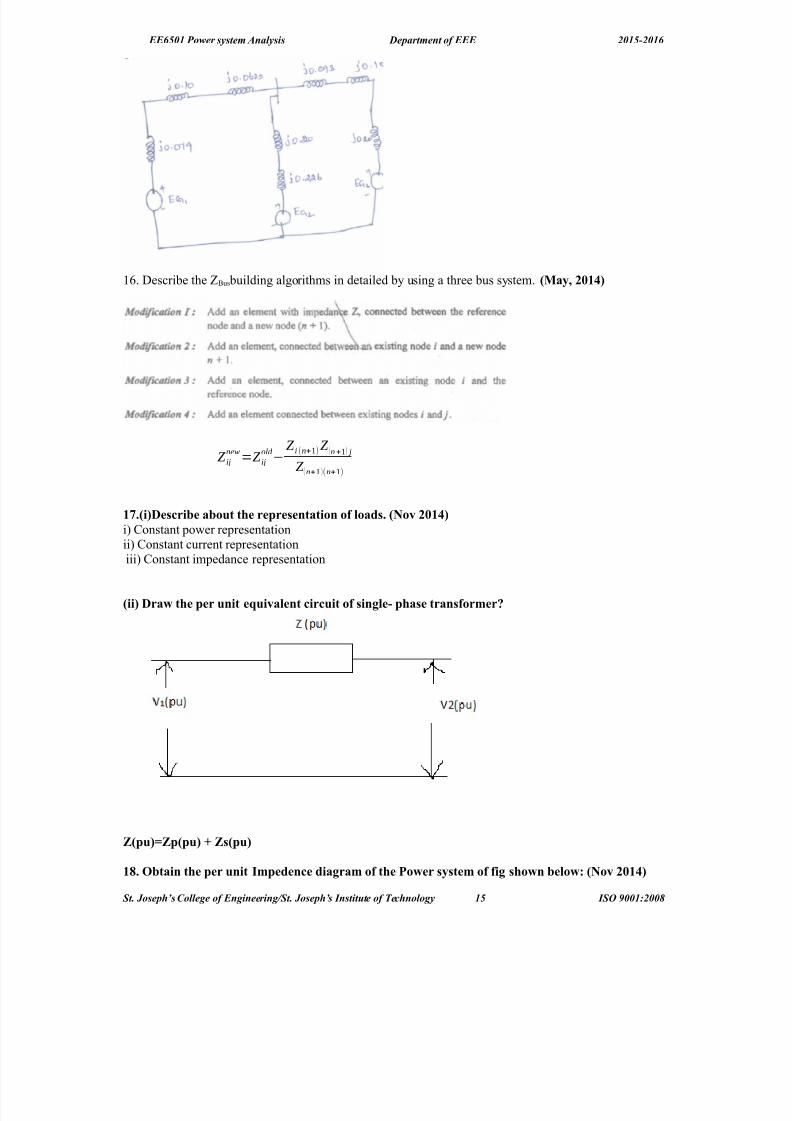
1. O#tain the per unit Impedene diagram of the Po,er s&stem of fig sho,n #e$o,B ?Nov "41*@
St. Joseph’s Collee of Enineerin!St. Joseph’s "nstit#te of $e%hnoloy 15 "S& '001(200)

8/18/2019 PSA qb 15-16 with answer.docx
http://slidepdf.com/reader/full/psa-qb-15-16-with-answerdocx 16/75
EE6501 Power system Analysis Department of EEE 2015-2016
ig one $ine diagram representation of a simp$e po,er s&stem.8enerator NoB' 1B%4 5)A6 14.+ Mv6 1.- ohms8enerator NoB' "B 1+ 5)A6 -.- Mv6 1." ohms8enerator NoB' %B"+ 5)A6 -.- Mv6 4.+- ohmsTransformer T1?% phase@B' 1+ 5)A 6 %%F11 (v 6 1+." ohms per phase on high tension side .Transformer T"?% phase@B' 1+ 5)A 6 %%F-." (v 6 1- ohms per phase on high tension sideTransmission $ine B "4.+ ohms per phase9oad A6 1+5W611()64.2 $agging po,er fator9oad >6 *45W6-.-()64.+ $agging po,er fator
<o$ution81 pu H4.**1pu
T1 puH4.%"-+puT9ine puH4.-12puT" puH4.*%pu8" pu H4.%1""pu8% pu'H4."1"% pu9oad A4.12"GH4.%"pu9oad >4."1+GH4.%+* pu
UNIT – II POWR 9OW ANA9L<I<PART – A
1. What is po,er f$o, stud& or $oad f$o, stud&! ?Nov "41*@The study of various methods of solution to power system networ* is referred to as load flow study. Thesolution provides the voltages at various buses, power flowing in various lines and linelosses.
". What is the need for $oad f$o, stud&!The load flow study of a power system is essential to decide the best operation of existing system and for planning the future expansion of the system. It is also essential for designing a new power system.
%. What are the different t&pes of #uses in a po,er s&stem!The buses of a power system can be classified into three types based on the quantities being specified for the buses. The different types of buses are,!i% #oad bus or DR bus !ii% Cenerator bus or voltage controlled bus or D" bus!iii% 8lac* bus !or% swing bus !or% reference bus
*. What ,i$$ #e the reative po,er and #us vo$tage ,hen the generator #us is treated as $oad #us!>hen the generator bus is treated as load bus, the reactive power of the bus is equated to the limit it hasviolated, and the previous iteration value of bus voltage is used for calculating current iteration value.
+. What are the advantages of 8'< method!i% alculations are simple so the programming tas* is less ii% the memory requirement is less iii% ?sefulfor small systems
-. What are the disadvantages of 8'< method!i% Lequires large number of iterations to reach convergence. ii% $ot suitable for large systems iii%onvergence time increases with siBe of the system
. What are the advantages of N'R method!i% The $L method is faster, more reliable and the results are accurate ii% Lequires less number of iterations for convergence.iii% The number of iterations is independent of the siBe of the system.vi%8uitable for large siBe system.
. What are the disadvantages of N'R method!i% Drogramming is more complex ii% The memory requirement is more iii% omputational time periteration is higher due to large number of calculations per iteration.
2. 3o, the disadvantages of N'R method are overome!
St. Joseph’s Collee of Enineerin!St. Joseph’s "nstit#te of $e%hnoloy 16 "S& '001(200)

8/18/2019 PSA qb 15-16 with answer.docx
http://slidepdf.com/reader/full/psa-qb-15-16-with-answerdocx 17/75
EE6501 Power system Analysis Department of EEE 2015-2016
The disadvantages of large memory requirement can be overcome by decoupling the wea* coupling between D S and R" !i.e using de coupled load flow algorithm%. The disadvantage of largecomputational time per iteration can be reduced by simplifying the decoupled load flow equations. Thesimplifications are made based on the practical operating conditions of a power system.14. 3o, are the diagona$ e$ements of L#us Mno,n as!The diagonal elements of bus are *nown as the short circuited driving point admittance or selfadmittanceof the buses.11. <tate the maHor steps invo$ved in $oad f$o, studies!
The ma;or steps involved in load flow studies are i% +athematical modeling of the power systemJ thiswould be a set of nonlinear algebraic equations. ii% 8olution of the nonlinear equations through aniterative technique.
1". Wh& ae$eration fator is used in the 8'< method! To increase the rate of convergence of the iterative process, acceleration factor is used.
1%. What are the appro0imations made in D9 method!i% Leal power at a bus does not change appreciably for a small change in the voltage magnitudeii% Leactive power at a bus does not change appreciably for a small change in bus voltage phase angle.
1*. What is the need of $oad f$o, so$ution!The load flow solution is essential for designing a new power system and for planning extension as wellas operation of the existing one for increased power demand.
1+. What is $oad #us!
( load bus is one at which the active power and reactive power are specified. In this bus its voltage can be allowed to vary within permissible values. i.e 2E. (lso bus voltages phase angle is not veryimportant for the load.
1-. 3o, the onvergene of N'R method is speeded up!The convergence of $L method is speeded up using fast decoupled load flow !=A#=% method. In =A#=,the wea* coupling between D" and R S are decoupled and the equations are further simplified equationsare further simplified using the practical operating conditions of the power system.
1. What are the advantages of deoup$ed method over N'R method!i% This method is simple and computationally efficient than the $L method.ii% It requires less memory compared to $L method.
1. What is the need for vo$tage ontro$ in a po,er s&stem!The various components of a power system !or equipments connected to power system% are designed to
wor* satisfactorily at rated voltages. If the equipments are not operated at rated voltages then the performance of the equipments will be poor and the life of the equipments will reduce. Hence thevoltages at various points in a power system should be maintained at rated value !specified value%
12. 3o, the reative po,er of a generator is ontro$$ed!The reactive power of a generator is controlled by varying the magnitude and phase of induced emf,which in turn varied by varying excitation. =or an increase in reactive power the magnitude of inducedemf is increased and its phase angle is decreased. =or a reduction in reactive power the magnitude of induced emf is decreased and its phase angle is increased.
"4. What is <$aM or s,ing #us!?5a& "411@( bus is called swing bus when the magnitude and phase of bus voltage are specified for it. The swing bus is the reference bus for load flow solution and it is required for accounting line losses. ?sually one of the generator bus is selected as the swing bus.
"1. What is ao#ian matri0! 3o, the e$ements of ao#ian matri0 are determined!?5a& "411@The matrix formed the first order derivatives of load flow equations is called Uacobian matrix !U%.Theelements of Uacobian matrix will change in every iteration. In each iteration the elements of this matrixare obtained by partial differentiating the load flow equations with respect to an un*nown variable andthen calculating the first derivatives using the solution of previous iteration."". What are the information that are o#tained from a po,er f$o, stud&! ?5a& "41"@)us voltages, #ine transformer power flows, and transmission power losses."%. Compare 8auss'seida$ and Ne,ton Raphson methods of $oad f$o, so$utions. ?5a& "41"@
<. N 8auss seida$ Ne,ton Raphson1. Leliable +ore reliable
St. Joseph’s Collee of Enineerin!St. Joseph’s "nstit#te of $e%hnoloy 1, "S& '001(200)

8/18/2019 PSA qb 15-16 with answer.docx
http://slidepdf.com/reader/full/psa-qb-15-16-with-answerdocx 18/75
EE6501 Power system Analysis Department of EEE 2015-2016
. Lequire large number of iterations toreach convergence. It has linear convergence characteristics
=aster. Lequire less number if iteration toreach convergence It has quadraticconvergence characteristics.
&. Drogramming tas* is less Drogramming is more complex.3. 8uitable for small siBe system and not
suitable for large system. $umber iterations increases with increase in siBe.
8uitable for large siBe system. $umber of iterations does not depend on siBeof the system.
2. +emory required is less +emory required is more."*. Wh& po,er f$o, ana$&sis is made!?Nov"41"@Dower flow analysis is performed to calculate the magnitude and phase angle of voltage at the buses andalso the active power and reactive volt amperes flow for the given terminal or bus conditions. Thevariables associated with each bus or node are i% magnitude of voltage !v% ii% phase angle of voltage !S%iii% active power !D% iv% reactive volt amperes !R%.
"+. What is ae$eration fator!?Nov"41"@ ?5a& "41%@The acceleration factor is a numerical multiplier which is used to increase which is used to increase therate of convergence in an iterative process. The previous value at the bus is multiplied by the accelerationfactor to obtain a correction to be added to previous values."-. What is the need of s$aM #us! ?5a& "41%@ ?5a& "41*@The slac* bus is needed to account for transmission line losses. In a power system the total power
generated will be equal to sum of power consumed by loads and losses. In a power system only thegenerated power and load power are specified for buses. The slac* bus is assumed to generate the power required for losses. 8ince the losses are un*nown the real and reactive power are not specified for slac* bus .They are estimated through the solution of load flow equations.
". Wh& do L>us used in $oad f$o, stud& instead of =>us! ?Nov "41%@ bus is sparsity matrix ie. $umber of nonBero elements is less compared to Bero elements. Henceformation of bus needs less memory.". When ,i$$ the generator #us #e treated as $oad #us! ?Nov "41%@ ?5a& "41*@If the reactive power of a generator bus violates the specified limits then the generator bus is treated asload bus."2. Define vo$tage ontro$$ed #us ?Novem#er "41*@ These are the buses where generators are connected. Therefore the power generation in such buses iscontrolled through a prime mover while the terminal voltage is controlled through the generator excitation. 'eeping the input power constant through turbinegovernor control and *eeping the busvoltage constant using automatic voltage regulator, we can specify constant P Gi and V V i |for these buses.This is why such buses are also referred to as D" buses. It is to be noted that the reactive power supplied by the generator QGi depends on the system configuration and cannot be specified in advance.=urthermore we have to find the un*nown angle δi of the bus voltage.
PART – >1. <tate the $oad f$o, pro#$em and derive $oad f$o, e/uation.. The study of various methods of solution to power system networ* is referred to as load flow
study. The solution provides the voltages at various buses, power flowing in various lines andlinelosses.
&. The load flow study of a power system is essential to decide the best operation of existingsystem and for planning the future expansion of the system. It is also essential for designing anew power system.
3. The buses of a power system can be classified into three types based on the quantities beingspecified for the buses. The different types of buses are,!i% #oad bus or DR bus !ii%Cenerator busor voltage controlled bus or D" bus!iii%8lac* bus !or% swing bus !or% reference bus
". ?a@ What are the pratia$ app$iation of the po,er f$o, ana$&sis ! ?#@ Derive the mathematia$ mode$ of phase shifting transformer to #e used in a po,er f$o,ana$&sis.
Dower flow analysis is performed to calculate the magnitude and phase angle of voltage at the busesand also the active power and reactive volt amperes flow for the given terminal or bus conditions. The
St. Joseph’s Collee of Enineerin!St. Joseph’s "nstit#te of $e%hnoloy 1) "S& '001(200)

8/18/2019 PSA qb 15-16 with answer.docx
http://slidepdf.com/reader/full/psa-qb-15-16-with-answerdocx 19/75
EE6501 Power system Analysis Department of EEE 2015-2016
variables associated with each bus or node arei% magnitude of voltage !v% ii% phase angle of voltage !S%iii% active power !D%iv% reactive volt amperes !R%. The load flow solution is essential for designing a new power system and for planning extensionas well as operation of the existing one for increased power demand.
!b% Aerive the mathematical model of phase shifting transformer to be used in a power flow analysis.
%. The fo$$o,ing is the s&stem data for a $oad f$o, so$utionB
The shedu$e of ative and reative po,er is
Determine the vo$tage at the end of first iteration using 8'< method. TaMe ae$eration fator 1.*.<o$utionBorm the L'>U<
)us/
[3− 12 −2+ 8 −1+ 4
−2+ 8 3.666− 14.664 −0.666+ 2.66−1+ 4 −0.666+ 2.664 3.666− 14.664
0
−1+ 4−2+ 8
0 −1+ 4 −2+ 8 −3− 2]
St. Joseph’s Collee of Enineerin!St. Joseph’s "nstit#te of $e%hnoloy 1' "S& '001(200)
>us ode Admittane1'" ".4'H.4
1'% 1.4'H%.4
"'% 4.-'H".4"'* 1.4'H*.4%'* ".4'H.4
>us ode P ) RemarMs1 ' ' 1.4+GH4.4 <$aM " 4.+ 4." 1.4GH4.4 P% 4.* 4.% 1.4GH4.4 P* 4.% 4.1 1.4GH4.4 P
8/18/2019 PSA qb 15-16 with answer.docx
http://slidepdf.com/reader/full/psa-qb-15-16-with-answerdocx 20/75
EE6501 Power system Analysis Department of EEE 2015-2016
)1*a1.2-'4.424++
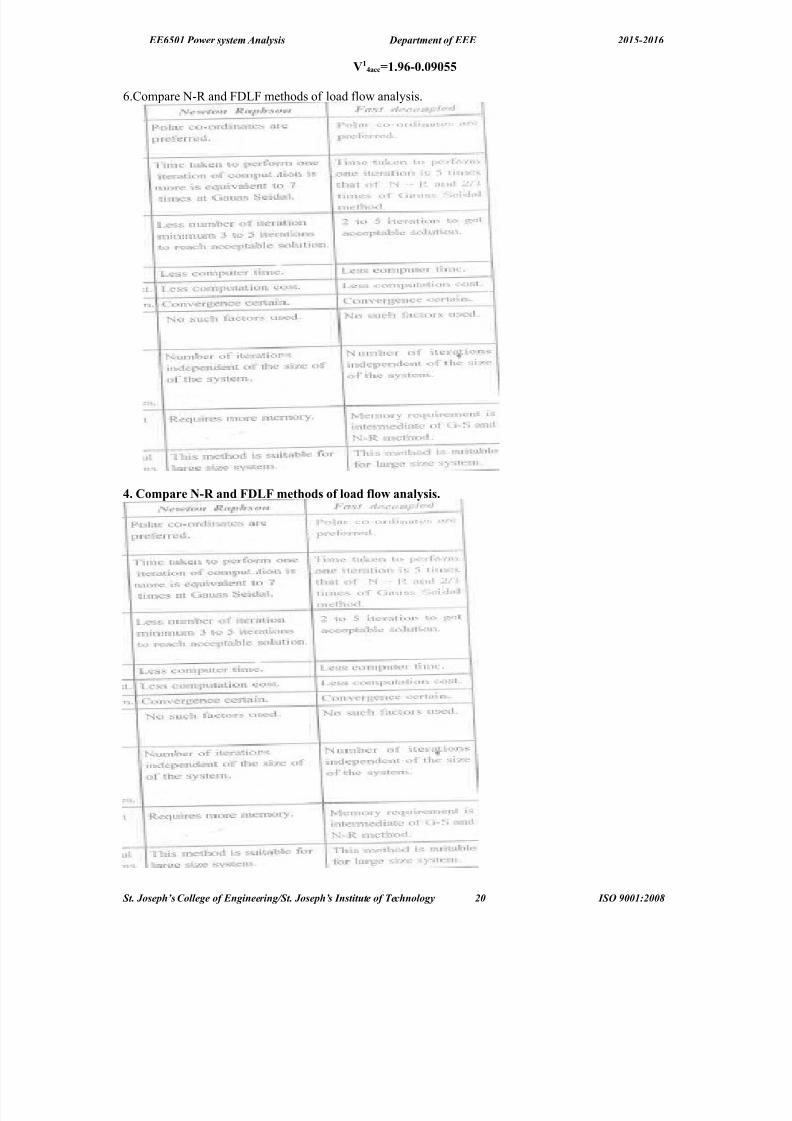
.ompare $L and =A#= methods of load flow analysis.
*. Compare N'R and D9 methods of $oad f$o, ana$&sis.
St. Joseph’s Collee of Enineerin!St. Joseph’s "nstit#te of $e%hnoloy 20 "S& '001(200)

8/18/2019 PSA qb 15-16 with answer.docx
http://slidepdf.com/reader/full/psa-qb-15-16-with-answerdocx 21/75
EE6501 Power system Analysis Department of EEE 2015-2016
+. With neat f$o, hart e0p$ain the omputationa$ proedure for $oad f$o, so$ution using astdeoup$ed method ,hen the s&stem ontains a$$ the t&pes of #uses.?5a& "411@
-. igure sho,s a five #us s&stem. ah $ine has an impedane of ?4.4+G H4.1+@ pu. The $ine shuntadmittane ma& #e neg$eted. The #us po,er and vo$tage speifiations are given in ta#$e.
?5a& "41"@>us P9 9 P8 8 ) >us <peifiation
1 1.4 4.+ ' ' 1.4" ∠0 <$aM #us
" 4 4 " ' 1.4" P) #us
% 4.+ 4." 4 4 ' P >us
* 4.+ 4." 4 4 ' P #us
+ 4.+ 4." 4 4 ' P #us
?i@ orm L#us ?ii@ ind "6 Q"6 )%6 )*6 and )+ after first iteration using 8auss seida$ method.Assume "min4."pu6 "ma0 4.-pu.
Sol#tion(
orm L>us 5atri0B
L>U<
[
4− 12 −2+ 6
−2+ 6 6− 18
0 0 −2+ 6
−2+ 6 0 −2+ 6
0 −2+ 6
0
−2+ 6
0
−2+ 6
4− 12 −2+ 6 0
−2+ 6
0
4− 12 −2+ 6
−2+ 6 6− 18
]"14."**pu
)"11.4"J+.11K p.u
)%1.2J4.-K p.u
)*14.2-%J'1.+%K p.u
)"
1
4.2%-J'4.4*K p.u
. What is ao#ian 5atri0! 3o, the e$ements of ao#ian matri0 are omputed! ?5a& "41"@?Nov"41"@
. Write the step #& step proedure for $oad f$o, ana$&sis #& Ne,ton Raphson method.?5a& "41"@ ?Nov "41*@ ?5a& "41*@
St. Joseph’s Collee of Enineerin!St. Joseph’s "nstit#te of $e%hnoloy 21 "S& '001(200)

8/18/2019 PSA qb 15-16 with answer.docx
http://slidepdf.com/reader/full/psa-qb-15-16-with-answerdocx 22/75
EE6501 Power system Analysis Department of EEE 2015-2016
2. Compare 8'< and N'R methods of $oad f$o, ana$&sis.?Nov "41"@
<. N 8auss seida$ Ne,ton Raphson
1. Leliable +ore reliable. Lequire large number of iterations to
reach convergence. It has linear convergence characteristics
=aster. Lequire less number if iteration toreach convergence It has quadraticconvergence characteristics.
&. Drogramming tas* is less Drogramming is more complex.
St. Joseph’s Collee of Enineerin!St. Joseph’s "nstit#te of $e%hnoloy 22 "S& '001(200)

8/18/2019 PSA qb 15-16 with answer.docx
http://slidepdf.com/reader/full/psa-qb-15-16-with-answerdocx 23/75
EE6501 Power system Analysis Department of EEE 2015-2016
3. 8uitable for small siBe system and notsuitable for large system. $umber iterations increases with increase in siBe.
8uitable for large siBe system. $umber of iterations does not depend on siBeof the system.
2. +emory required is less +emory required is more.
14. The figure given #e$o, sho,s a po,er s&stem. ?Nov "41"@>us 1B <$aM #us <peified1.4+J4K E>us "B P) #us <peified 1." p.u P8 % p.uE >us %B P #us
P9
* p.u 9
" p.u .Carr& out one iteration of$oad f$o, so$ution #& 8auss'<eida$ method. TaMe $imits of generator " as 0%Q<4 TaMeS 1.
<o$utionB
L>U<
[
3−9 −2+5 −1+4
−2+5 5−14 −3+9
−1+4 −3+9 4−13
]
"'4."+p.u6 P"%)"
4.2%-G4.1H)%
4.%'4.11%*H
11. Consider the po,er s&stem ,ith the fo$$o,ing dataB
>us No. T&pe 8eneration 9oad )o$tageP P 5agnitude Ang$e
1 <$aM ' ' ' ' 1.4 44
" P') +.4 ' 4 4 1.4+ '% P' 4 4 %.4 4.+ ' '
L>us [− 12 8 4
8 − 12 4
4 4 − 8]
O#tain the po,er f$o, so$ution ?one iteration@ for the given s&stem . The $ine admittane are inper unit on a 144 5)A #ase. Use fast deoup$ed $oad f$o, method.
>us No. T&pe 8eneration 9oad )o$tageD R D R +agnitude (ngle
1 8lac* 1.0 00
D" 2.0 0 0 1.02 & DR 0 0 &.0 0.2
St. Joseph’s Collee of Enineerin!St. Joseph’s "nstit#te of $e%hnoloy 2* "S& '001(200)

8/18/2019 PSA qb 15-16 with answer.docx
http://slidepdf.com/reader/full/psa-qb-15-16-with-answerdocx 24/75
EE6501 Power system Analysis Department of EEE 2015-2016
)us / [− 12 8 4
8 − 12 4
4 4 − 8]
<btain the power flow solution !one iteration% for the given system . The line admittance are in perunit on a 100 +"( base. ?se fast decoupled load flow method.
<o$utionB
[B & ]=[ 12 −8
−8 12 ] [B & & ]= [12 ]
"4.-
)"4.%G4.+--H
)%4.2*'4.421-H
1". A three #us po,er s&stem is sho,n in figure. The re$evant per unit $ine admittane on 144 5)A#ase are indiated on the diagram and #us data are given in ta#$e. ormL>usand determine thevo$tage at #us " and #us % after first iteration using 8< method. TaMe the ae$eration fator S 1.- ?Nov6 "41%@
>us No. T&pe 8eneration 9oad )o$tageP P 5agnitude Ang$e
1 <$aM ' ' ' ' 1.4" 44
" P' "+ 1+ +4 "+ ' '% P' 4 4 -4 %4 ' '
<o$utionB
)us / [− 7 3 4
3 − 8 5
4 5 − 9]
211.0*)70.06258
*10.6170.56)8
1%. ?i@ 8ive the $assifiation of various t&pes of #uses in a po,er s&stem for $oad f$o, studies. ?Nov "41*@ ?Nov "41*@
St. Joseph’s Collee of Enineerin!St. Joseph’s "nstit#te of $e%hnoloy 2+ "S& '001(200)

8/18/2019 PSA qb 15-16 with answer.docx
http://slidepdf.com/reader/full/psa-qb-15-16-with-answerdocx 25/75
EE6501 Power system Analysis Department of EEE 2015-2016
The buses of a power system can be classified into three types based on the quantities beingspecified for the buses. The different types of buses are,!i% #oad bus or DR bus !ii%Cenerator busor voltage controlled bus or D" bus!iii%8lac* bus !or% swing bus !or% reference bus
?ii@ 8ive the advantages and $imitations of Ne,ton Raphson method. ?iii@What is meant #& deoup$ed $oad f$o, method! ?Nov "41%@
+ore reliable=aster. Lequire less number if iteration to reach convergence It has quadratic convergencecharacteristics.
Drogramming is more complex.8uitable for large siBe system. $umber of iterations does not depend on siBe of the system.
+emory required is more.
1*. ormu$ate the po,er f$o, e/uation for n #us s&stem. ?5a& "41*@
The complex power injected by the source into the ith bus of a power system is
Si=Pi+JQi
The current injected at the ith node is given by
1+. Desri#e the step #& step proedure for $oad f$o, so$ution from 8auss sieda$ method6 if P) andP #uses are present a$ong ,ith s$aM #us. ?5a& "411@ ?5a& "41%@6 ?5a& "41*@.
St. Joseph’s Collee of Enineerin!St. Joseph’s "nstit#te of $e%hnoloy 25 "S& '001(200)

8/18/2019 PSA qb 15-16 with answer.docx
http://slidepdf.com/reader/full/psa-qb-15-16-with-answerdocx 26/75
EE6501 Power system Analysis Department of EEE 2015-2016
St. Joseph’s Collee of Enineerin!St. Joseph’s "nstit#te of $e%hnoloy 26 "S& '001(200)

8/18/2019 PSA qb 15-16 with answer.docx
http://slidepdf.com/reader/full/psa-qb-15-16-with-answerdocx 27/75
EE6501 Power system Analysis Department of EEE 2015-2016
1-. ig. sho,n #e$o, a three #us po,er s&stem >us 1B <$aM #us )<peified1.4+J4K E>us "B P) #us )<peified 1.4 p.u 6P8 % p.uE >us %B P #us P9 * p.u 9" p.u .Carr& out one iteration of $oad
f$o, so$utions #& 8auss <eide$ method. Neg$et $imits on reative po,er generation! ?Nov "41*@
<o$ution
St. Joseph’s Collee of Enineerin!St. Joseph’s "nstit#te of $e%hnoloy 2, "S& '001(200)

8/18/2019 PSA qb 15-16 with answer.docx
http://slidepdf.com/reader/full/psa-qb-15-16-with-answerdocx 28/75
EE6501 Power system Analysis Department of EEE 2015-2016
L #us 'H+.% H".+ H%.%% H".+ 'H.+ H+ H%.%% H+ 'H.%%
)"1J'".- o
)%4.2*J'+."" o
UNIT – III AU9T ANA9L<I< ' >A9ANCD AU9TPART – A
1. What is <hort Ciruit 5)A and ho, it is a$u$ated!The short circuit capacity or the short circuit +"( at a bus is defined as the product of the magnitudes of the rated bus voltage and the fault current. 8. +"( capacity of the circuit brea*er / √ & x pre faultvoltage in '" x 8. current in '(.". What are the t&pes of fau$ts!8:LI:8 =(?#T a% <ne open conductor fault b% Two open conductor fault8H?$T =(?#T !a% 8ymmetrical or balanced fault !i% Three phase =ault!###C%!b% ?nsymmetrical or unbalanced fault ! i% #ine to line fault!##%!ii% #ine to ground fault !#C%!iii% Aouble line to ground fault.!##C%.%. What are the fators to #e onsidered for se$eting the C.>.!The factors to be considered in selecting a circuit brea*er for a protection scheme are $ormal operatingvoltage, +omentary, interrupting current. 8peed of the brea*er and 8. interrupting +"(.*. What &ou mean #& s&mmetria$ fau$ts! ?Novem#er "41*@The fault is called symmetrical fault if the fault current is equal in all the phases and the phase difference between any two phases is equal.+. What &ou mean #& dou#$ing effet!
The first pea* of the resultant current will become twice the pea* value of the final steady current. Thiseffect is called as doubling effect.-. What &ou mean #& transient and su# transient reatane!FdW !transient reactance% is the ratio of no load e.m.f and the transient symmetrical r.m.s current.FdWW !sub transient reactance% is the ratio of no load e.m.f and the sub transientsymmetricalr.m.s current.. What is the app$iation of transient reatane!The transient and sub transient reactance helps in calculating the interrupting and maximum momentarys.c currents.. 8ive the various assumptions made for fau$t ana$&sis.The assumptions made in analysis of faults arei% :ach synchronous machine model is represented by ane.m.f behind a series reactance ii% In the transformer models the shunt that account for core loss andmagnetiBing components are neglected.iii% In the transmission line models the shunt capacitances are
neglected. iv%(ll series resistances in generators, transformers, lines are neglected. v% In the normaloperating conditions the pre fault voltage may be considered as 1.0 p.u.vi% #oad impedances areneglectedJ hence the pre fault system may be treated as unloaded. vii% (s the pre fault currents are muchsmaller than the post fault currents the pre fault currents can be neglected.2. Name an& methods of reduing short iruit urrent.)y providing neutral reactances and by introducing a large value of shunt reactances between buses.14.What are the reatanes used in the ana$&sis of s&mmetria$ fau$ts on the s&nhronous mahines
as its e/uiva$aent reatanes. i% 8ubtransient reactance Fd
N ii% Transient Leactance FdW iii% 8ynchronous reactance Fd
11. What is s&nhronous reatane!It is the ratio of induced emf and the steady state r.m.s current. Fd /:g I
St. Joseph’s Collee of Enineerin!St. Joseph’s "nstit#te of $e%hnoloy 2) "S& '001(200)
8/18/2019 PSA qb 15-16 with answer.docx
http://slidepdf.com/reader/full/psa-qb-15-16-with-answerdocx 29/75
EE6501 Power system Analysis Department of EEE 2015-2016
It is the sum of lea*age reactance and the armature reaction reactances. It is given byF d / Fl K Fa,Fd /8ynchronous reactance. Fl / #ea*age reactance Fa / (rmature reaction reactance.1".What are the auses of fau$t in po,er s&stem.( fault may occur on a power system due to a number of reasons. 8ome of the causes are!i% Insulationfailure of the system!ii% =alling of a tree along a line!iii% >ind and ice loading on the transmissionlines!iv% "ehicles colliding with supporting structures!v% <verloading of underground cables!vi% )irdsshorting the lines.1%. Name the main differenes in representation of po,er s&stem for $oad f$o, and short iruits
studies<.N
9oad f$o, studies <hort iruit studies
1 The resistances and reactances areconsidered
The resistances are neglected
To solve load flow analysis, the busadmittance matrix is used
To solve load flow analysis, the busimpedance matrix is used
& It is used to determine the exact voltages andcurrents
Dre fault voltages are assumed to be 1 p.uand the pre fault current can be neglected
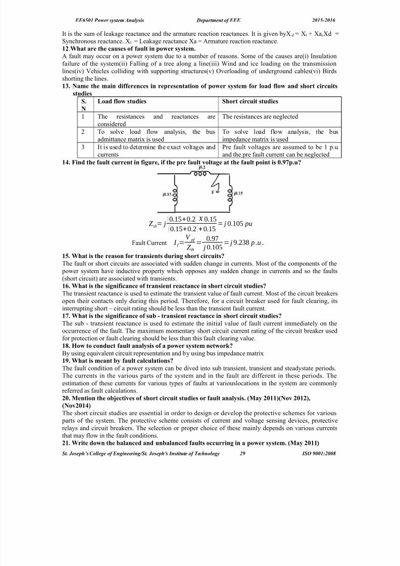
1*. ind the fau$t urrent in figure6 if the pre fau$t vo$tage at the fau$t point is 4.2p.u!
Z t'= ( 0.15+0.2) X 0.15
( 0.15+0.2 )+0.15= 0.105 pu
=ault urrent I ( =V p(
Z t'=
0.97
0.105= 9.238 p )u )
1+. What is the reason for transients during short iruits!The fault or short circuits are associated with sudden change in currents. +ost of the components of the
power system have inductive property which opposes any sudden change in currents and so the faults!short circuit% are associated with transients.1-. What is the signifiane of transient reatane in short iruit studies!The transient reactance is used to estimate the transient value of fault current. +ost of the circuit brea*ersopen their contacts only during this period. Therefore, for a circuit brea*er used for fault clearing, itsinterrupting short P circuit rating should be less than the transient fault current.1. What is the signifiane of su# ' transient reatane in short iruit studies!The sub transient reactance is used to estimate the initial value of fault current immediately on theoccurrence of the fault. The maximum momentary short circuit current rating of the circuit brea*er usedfor protection or fault clearing should be less than this fault clearing value.1. 3o, to ondut fau$t ana$&sis of a po,er s&stem net,orM!)y using equivalent circuit representation and by using bus impedance matrix
12. What is meant #& fau$t a$u$ations!The fault condition of a power system can be dived into sub transient, transient and steadystate periods.The currents in the various parts of the system and in the fault are different in these periods. Theestimation of these currents for various types of faults at variouslocations in the system are commonlyreferred as fault calculations."4. 5ention the o#Hetives of short iruit studies or fau$t ana$&sis. ?5a& "411@?Nov "41"@6?Nov"41*@The short circuit studies are essential in order to design or develop the protective schemes for various parts of the system. The protective scheme consists of current and voltage sensing devices, protectiverelays and circuit brea*ers. The selection or proper choice of these mainly depends on various currentsthat may flow in the fault conditions."1. Write do,n the #a$aned and un#a$aned fau$ts ourring in a po,er s&stem. ?5a& "411@
St. Joseph’s Collee of Enineerin!St. Joseph’s "nstit#te of $e%hnoloy 2' "S& '001(200)

8/18/2019 PSA qb 15-16 with answer.docx
http://slidepdf.com/reader/full/psa-qb-15-16-with-answerdocx 30/75
EE6501 Power system Analysis Department of EEE 2015-2016
)(#($:A =(?#T & phase short circuit fault?$)(#($:A =(?#T 8ingle line to ground fault, line to line fault and double line to ground fault."". Distinguish s&mmetria$ and uns&mmetria$ fau$t. ?Nov "41"@ ?5a& "41%@The fault is called 8ymmetrical fault if the fault current is equal in all the phases.eg. & short circuit fault.ϕ
The fault is called unsymmetrical fault if the fault current is not equal in all the three phases. eg.i% singleline to ground fault ii% line to line fault iii% double line to ground fault iv% open conductor fault"%. What is meant #& fau$t $eve$! ?5a& "41%@It relates to the amount of current that can be expected to flow out of a bus in to a & phase fault.=ault level in +"( at bus i=V i puno*inal∗ I i pu(ault ∗+3ϕbase ."*. 8ive the fre/uen& of various fau$ts ourrene in asending order?Nov "41%@ ?5a& "41*@
T&pes of au$ts Re$ative re/uen& of Ourrene of au$ts
& phase fault 2EAouble #ine to Cround =ault 10E#ine to #ine =ault 12E8ingle #ine to Cround =ault 40E
"+. Define #o$ted fau$t. ?5a& "41*@( fault represents a structural networ* change equivalent with that caused by the addition of impedance at
the place of the fault. If the fault impedance is Bero, then the fault is referred as bolted or solid fault.PART – >
1.( 8ynchronous generator rated 200 '"(, 300", 0.1 p.u, sub transient reactance is supplying a passiveload of 300'> at 0.5 lag p.f. alculate the initial symmetrical L+8 current for a & fault at theϕ
generator terminals.<o$utionB9oad Current 4.-+-A>ase Current 4.-+-AP.u Current 1 p.u
#& & =V + I L X d=1+ 0.1
I?1'14H@ p.uInitia$ rms Current?4.-+- – -.+-H@ A. Two generating stations having 8. capacities of 1200+"( Q 1000+"( respectively and operating at
11 '" are lin*ed by a interconnected cable having s reactance of 0.Ωphase. Aetermine 8. capacity
of each station.<o$utionB9et >ase 1+44 5)Aor 8enerating <tation?1@B5)As5)AsF1
11 p.uor 8enerating <tation?"@B5)As5)AsF"
11.+p.up.u of a#$e.*% p.uWhen au$t in generating <tation?1@e/4.22H
5)As1--.+5)AWhen au$t in generating <tation?"@e/1."%+H p.u5)As11.+ 5)A&. Two synchronous motors are connected to the bus of a large system through a short transmission line as
shown. The ratings of the various components are+otor each 1+"(, 330", 0.1p.u reactance.#ine0.02Ω reactance. #arge system 8. +"( at 330" bus is 5.0. >hen two motors are in operationat 330", calculate the 8. current !symmetrical% fed into a & phase fault at the motors.
<o$utionB>ase impedane6=#4.12%-p.u reatane of transmission $ine 4."+%p.u
St. Joseph’s Collee of Enineerin!St. Joseph’s "nstit#te of $e%hnoloy *0 "S& '001(200)

8/18/2019 PSA qb 15-16 with answer.docx
http://slidepdf.com/reader/full/psa-qb-15-16-with-answerdocx 31/75
EE6501 Power system Analysis Department of EEE 2015-2016
=thH4.4*12p.uThe p.u va$ue of fau$t urrent If "1.-2J'24K p.uThe Atua$ va$ue of fau$t urrent If ".*J'24K (A.3. ( small generating station has a bus bar divided into three sections. :ach section is connected to a tie
bar with reactors each rated at 2+"(, 0.1p.u reactance. ( generator of 5 +"( rating and 0.12 p.ureactance is connected to each section of the bus bar. Aetermine the 8. capacity of the brea*er if a & phase fault ta*es place on one of the sections of the bus bar.
<o$utionBTota$ reatane4.14%% p.uau$t 5)A.*15)A2. (n alternator and a synchronous motor each rated for 20 +"(, 1&. '" having sub transient of 0E
are connected through a transmission lin* of reactance 10E on the base of machine ratings. The motor acts as a load of &0 +> at 0.5 p.f lead and terminal voltage 1.2 '" when a & phase fault ta*es place atthe motor terminals. Aetermine the sub transient current in the alternator, the motor and the fault.
<o$utionB>ase 5)A +45)A>ase )o$tage1%." ()>ase Current"1-.2%A9oad Current4.2"4 p.u>& taMing ) as referene phase6$oad urrent isI?4.-%%-G4.*+"[email protected]$t )o$tage at motor termina$s4.2*-2p.uNet reatane as seen from fau$t pointH4.1"p.uTota$ fau$t Current 'H.2p.uau$t urrent <upp$ied #& generator'H%.1+-p.uau$t Current supp$ied #& motor'H*.%* p.uTota$ post fau$t generator urrent -41*.4+ATota$ post fau$t motor urrent11**."ATota$ fau$t urrent"1-+4.-4A. ( 8tation operating at && '" is divided into sections ( Q ). 8ection ( consists of three generators 12
+"( each having a reactance of 12E and section ) is fed from the grid through a 42 +"(transformer of 5E reactance. The c*t brea*ers have each a rupturing capacity of 420 +"(. Aetermine
the reactance of the reactor to prevent the brea*ers being over loaded if a symmetrical 8. occurs onan outgoing feeder connected to (
<o$utionB>ase 5)A as +5)AThe p.u reatane of eah generator H4.+p.uThe p.u reatane of eah transformerH4.4p.u<hort Ciruit 5)A>ase 5)AFp.u impedane4.44+p.uAtua$ )a$ue of reatane in 1."-*
. The per unit impedance matrix of a four bus power system shown in figure below,
@)us/
[ 0.15 0.075
0.075 0.1875
0.14 0.135
0.09 0.0975 0.14 0.09
0.135 0.0975
0.2533 0.21
0.21 0.2475]alculate the fault current for a solid three symmetrical fault at bus 3. (lso calculate the post fault busvoltages and line currents.<o$utionBau$t Current I( ?@'*.4*H p.uau$t )o$tagesB)1?@4.*+*- p.u)"[email protected])%[email protected]+1-p.u
St. Joseph’s Collee of Enineerin!St. Joseph’s "nstit#te of $e%hnoloy *1 "S& '001(200)

8/18/2019 PSA qb 15-16 with answer.docx
http://slidepdf.com/reader/full/psa-qb-15-16-with-answerdocx 32/75
EE6501 Power system Analysis Department of EEE 2015-2016
)*[email protected]'%p.u5.:xplain symmetrical fault analysis using @bus matrix with neat flow chart .?5a& "411@?Nov "41"@?5a& "41%@
6. ( & 2+"( . '" alternator with a reactance of 5E is connected to a feeder of series impedanceϕ
0.1K;0.35 M'm.The transformer is rated at & +"( .*"&& '" and has a reactance of 2E.Aetermine the fault current supplied by the generator operating under no load with a voltage of .6'", when a & symmetrical fault occurs at a point 12 'm along the feeder.ϕ .?5a& "41"@.
<o$utionBAtua$ va$ue of indued emf g-.2()p.u va$ue of indued emf6g1.4*++ p.uAtua$ va$ue of prefau$t vo$tage6)pf %*.+()p.u va$ue of prefau$t vo$tage6)pf 1.4*++ p.up.u reatane of the generator 6d4.4p.up.u reatane of the transformer T4.4%%p.up.u va$ue of the impedane of the feeder = feed4.44%GH4.4%%1p.up.u va$ue of the fau$t urrent6If +.%12J'.-Kp.u.>ase Current I#.*% AAtua$ va$ue of fau$t urrent If *-+."J'.-KA
St. Joseph’s Collee of Enineerin!St. Joseph’s "nstit#te of $e%hnoloy *2 "S& '001(200)

8/18/2019 PSA qb 15-16 with answer.docx
http://slidepdf.com/reader/full/psa-qb-15-16-with-answerdocx 33/75
EE6501 Power system Analysis Department of EEE 2015-2016
10. The bus impedance matrix of 3bus system with values in p.u is given by,
@)us/ [0.15 0.08 0.04
0.08 0.15 0.06
0.04 0.06 0.13
0.07
0.09
0.05
0.07 0.09 0.05 0.12]
In this system generator are connected to buses 1 and and their sub transient reactances included
when finding @)us. If prefault current is neglected, find sub transient current in p.u in the fault for a & ph fault on bus3.(ssume prefault voltage as 1 p.u. If the sub transient reactance of generator in )us is 0.p.u., find the sub transient fault current supplied by generator. ?5a& "41"@<o$utionB
)pf prefau$t vo$tage at #us '*1J4Kp.u.
I ( & & =¿ .%%%J'24Kp.u
V 2=V p( − I ( & & Z 24 4."+J4Kp.u.
11. =or the radial networ* shown, a &X fault occurs at =.Aetermine the fault current and the line voltageat 11 '" bus under fault condition. ?Nov6"41"@
<o$utionBP.u va$ue of impedane of8enerator 1B H4.1+ p.u8enerator "BH4.1"+ p.uTransformer 1BH4.1Transmission $ineB4.4**GH4.422" p.uTransformer "BH4.1- p.uCa#$eB4.42%GH4.4++ p.u.If 4.-*"+' H1.+1.2+2J'4.+Kp.u.I>*. AIf 11* A)o$tage at 11 () #us 2.-1+ ()1. ( synchronous generator and motor are rated &0 +"(, 1&. '" and both have sub transient reactance
of 0 E.The line connecting them has reactance of 10E on the base of machine ratings. The motor isdrawing 0,000 '> at 0.5 p.f leading and terminal voltage of 1.5 '" when a symmetrical & phasefault occurs at the motor terminals. =ind the sub transient current in the generator, motor and fault byusing internal voltages of machines.? 5a& "41%@
<o$utionB >ase Current I#1%1".- AAtua$ va$ue of prefau$t vo$tage at fau$t point6) tm1".()p.u va$ue of prefau$t vo$tage at fau$t point )tm4.2-2 p.uAtua$ )a$ue of rea$ po,er of the $oad6Pm"4 5W64. $ead
St. Joseph’s Collee of Enineerin!St. Joseph’s "nstit#te of $e%hnoloy ** "S& '001(200)
8/18/2019 PSA qb 15-16 with answer.docx
http://slidepdf.com/reader/full/psa-qb-15-16-with-answerdocx 34/75
EE6501 Power system Analysis Department of EEE 2015-2016
p.u.va$ue of rea$ po,er of the $oad Pm4.--- p.u.p.u va$ue of magnitude of $oad urrent 4.+2* p.u.<u#transient fau$t urrent in generator Ig
;%.-J'+.K(A<u#transient fau$t urrent in motor 6Ig
;.422"J'2.%K (A<u#transient urrent in the fau$t If
;14.-4J'24K (A1&. ( 11 '", 100 +"( alternators having a sub Ptransient reactance of 0.2 p.u is supplying a 20 +"(
motor having a sub Ptransient reactance of 0. p.u through a transmission line. The line reactance is0.02 pu on a base of 100 +"(. +otor is drawing 30 +> at 0.5 power factor leading with a terminalvoltage of 10.62 '" when a &phase fault occurs at the generator terminals. alculate the total currentin the generator and motor under fault conditions.?Nov "41%@?5a& "411@.
<o$utionB>ase 5)A1445)A>ase )o$tage11()>ase Current+"*.A9oad Current"-%-.*A5otor termina$ )o$tage4.22+p.u
Tota$ fau$t Current 4.1"+'H-.42p.uau$t urrent <upp$ied #& generator4.4'H%.21p.uau$t Current supp$ied #& motor4.4*+'H".1 p.uTota$ post fau$t generator urrent 1214+.-J'".*K ATota$ post fau$t motor urrent1%1*J"-1.K A
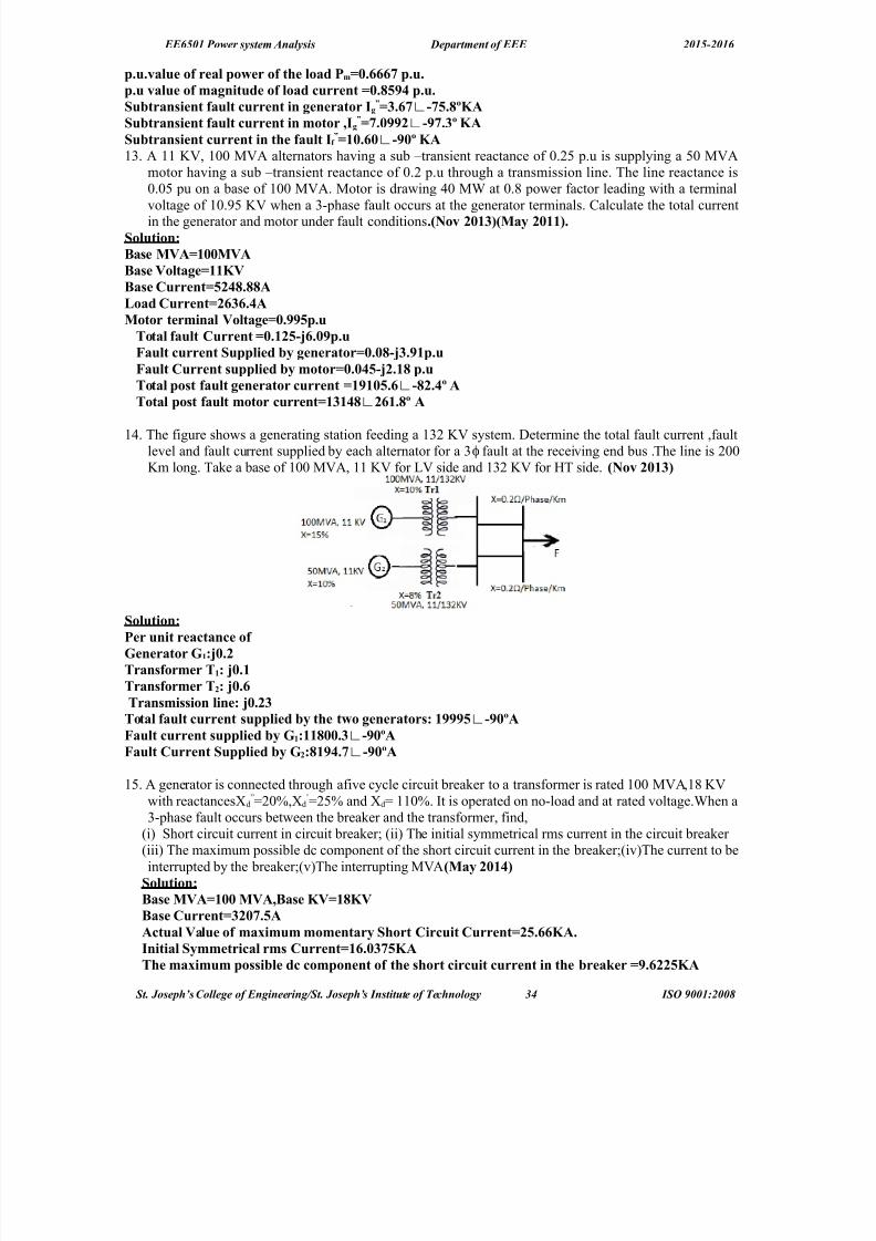
13. The figure shows a generating station feeding a 1& '" system. Aetermine the total fault current ,faultlevel and fault current supplied by each alternator for a & fault at the receiving end bus .The line is 00ϕ
'm long. Ta*e a base of 100 +"(, 11 '" for #" side and 1& '" for HT side. ?Nov "41%@
<o$utionBPer unit reatane of8enerator 81BH4."Transformer T1B H4.1Transformer T"B H4.- Transmission $ineB H4."%Tota$ fau$t urrent supp$ied #& the t,o generatorsB 1222+J'24KAau$t urrent supp$ied #& 81B1144.%J'24KAau$t Current <upp$ied #& 8"B12*.J'24KA
12. ( generator is connected through afive cycle circuit brea*er to a transformer is rated 100 +"(,15 '"with reactancesFdN/0E,Fd
W/2E and Fd/ 110E. It is operated on noload and at rated voltage.>hen a&phase fault occurs between the brea*er and the transformer, find,
!i% 8hort circuit current in circuit brea*erJ !ii% The initial symmetrical rms current in the circuit brea*er !iii% The maximum possible dc component of the short circuit current in the brea*erJ!iv%The current to beinterrupted by the brea*erJ!v%The interrupting +"(?5a& "41*@
<o$utionB>ase 5)A144 5)A6>ase ()1()>ase Current%"4.+AAtua$ )a$ue of ma0imum momentar& <hort Ciruit Current"+.--(A.Initia$ <&mmetria$ rms Current1-.4%+(AThe ma0imum possi#$e d omponent of the short iruit urrent in the #reaMer 2.-""+(A
St. Joseph’s Collee of Enineerin!St. Joseph’s "nstit#te of $e%hnoloy *+ "S& '001(200)

8/18/2019 PSA qb 15-16 with answer.docx
http://slidepdf.com/reader/full/psa-qb-15-16-with-answerdocx 35/75
EE6501 Power system Analysis Department of EEE 2015-2016
The urrent to #e interrupted #& the #reaMer 1*.11%(AThe interrupting 5)A **45)A
1. >ith the help of adetailed algorithm,:xplain how a
symmetrical fault can be analysed using @)us
?5a& "41*@
St. Joseph’s Collee of Enineerin!St. Joseph’s "nstit#te of $e%hnoloy *5 "S& '001(200)

8/18/2019 PSA qb 15-16 with answer.docx
http://slidepdf.com/reader/full/psa-qb-15-16-with-answerdocx 36/75
EE6501 Power system Analysis Department of EEE 2015-2016
St. Joseph’s Collee of Enineerin!St. Joseph’s "nstit#te of $e%hnoloy *6 "S& '001(200)

8/18/2019 PSA qb 15-16 with answer.docx
http://slidepdf.com/reader/full/psa-qb-15-16-with-answerdocx 37/75
EE6501 Power system Analysis Department of EEE 2015-2016
1. or the three #us net,orM ig. sho,n #e$o,6 o#tain = #us #& #ui$ding a$gorithm ?Nov "41*@
<o$utionB =#us(¿ )
UNIT – I) AU9T ANA9L<I< –UN>A9ANCD AU9TPART – A
St. Joseph’s Collee of Enineerin!St. Joseph’s "nstit#te of $e%hnoloy *, "S& '001(200)

8/18/2019 PSA qb 15-16 with answer.docx
http://slidepdf.com/reader/full/psa-qb-15-16-with-answerdocx 38/75
EE6501 Power system Analysis Department of EEE 2015-2016
1. Name the fau$ts invo$ving ground.The faults involving ground are single line to ground fault ii% double line to ground fault iii%Three phasefault". Define positive se/uene impedane.The negative sequence impedance of equipment is the impedance offered by the equipment to the flow of positive sequence currents.%. In ,hat t&pe of fau$t the Gve se/uene omponent of urrent is e/ua$ in magnitude #ut opposite
in phase to negative se/uene omponents of urrent!
#ine to line fault.*. In ,hih fau$t the negative and Vero se/uene urrents are a#sent!In three phase fault the negative and Bero sequence currents are absent.+. What are the #oundar& ondition in $ine'to'$ine fau$t!
Ia/0J IaKIc/0J " b/"c
-. Write do,n the #oundar& ondition in dou#$e $ine to ground fau$t!Ia/0J " b/0J "c/0
. 8ive the #oundar& ondition for the %'phase fau$t.Ia K I b / Ic/0J "a/" b/"c/0
. Name the fau$t in ,hih positive6 've and Vero se/uene omponent urrents are e/ua$.?5a& "41"@
In single line to ground fault the Kve, ve and Bero sequence component currents are equal2. Name the various uns&mmetria$ fau$ts in a po,er s&stem.i% single line to ground fault ii% line to line fault iii% double line to ground fault iv% open conductor fault14.Write a short notes on =ero se/uene net,orM.>hile drawing the Bero sequence networ* of a given power system, the following points may be *ept inview.The Bero sequence currents will flow only if there is a return path i.e.path from neutral to ground or to another point in the circuit.In the case of a system with no return path for Bero sequence currents, thesecurrents cannot exist.11.Write a short notes on negative se/uene net,orM.The negative sequence networ* can be readiley obtained from positive sequence networ* with thefollowing modificationsi%<mit the emfs of & P phase generators and motors in the positive sequencenetwor*. It is because these devices have only positive sequence generated voltages.ii%hange, if neccesary, the impedances between the generators neutral and ground pass no negative sequence current
and hence are not included in the negative seqeunce networ*.iii%=or static devices such as transmissionlines and transformers, the negative sequence impedances have the same value as the corresponding positive sequence impedances.1".Write a short notes on positive se/uene net,orM.>hile drawing the positive sequence networ* of a given power system, the following points may be*ept in view:ach generator in the system is represented by the generated voltage in series withappropriate reactance and resistance.urrent limiting impedances between the generators neutral andground pass no positive sequence current and hence are not included in the positive sequence networ*.(llresistance and magnetiBing currents for each transformer are neglected as a matter of simplicity.=or transmission lines, the shunt capacitances and resistances are generally neglected.1%.3o, ,i$$ &ou e0press positive6 negative and Vero – se/uene impedanes of L – onneted $oads!
Dositive seqence impedance mn s
Z Z Z Z &1++=
.$egative sequence impedance m s
Z Z Z −=
@ero sequence impedance m s Z Z Z −=0
>here, @s / self impedance of P connected load, @n/ loadneutral impedance @m / +utual impedance.1*. Whih is the most fre/uent$& ourring fau$t!8ingle line to ground fault is the most frequently occurring fault1+. Define uns&mmetria$ fau$t.The fault is called unsymmetrical fault if the fault current isnot same in all the three phases.1-. Whih is the most severe fau$t in po,er s&stem!Three phase fault is the most severe and rarely occurring fault in the power system.1. What is se/uene net,orM! ?5a& "411@
St. Joseph’s Collee of Enineerin!St. Joseph’s "nstit#te of $e%hnoloy *) "S& '001(200)

8/18/2019 PSA qb 15-16 with answer.docx
http://slidepdf.com/reader/full/psa-qb-15-16-with-answerdocx 39/75
EE6501 Power system Analysis Department of EEE 2015-2016
The networ* which is used to represent the positive, negative and Bero sequence components of unbalanced system is called as sequence networ* 1. What are the s&mmetria$ omponents of a three phase s&stem! ?5a& "411@?Nov "41"@ ?Nov"41*@1% Dositive sequence % negative sequence &% @ero sequence12. What is meant #& a au$t! ?5a& "41"@( fault in a circuit is any failure which interferes with the normal flow of current .The faults areassociated with abnormal change in current, voltage and frequency of the power system. The faults maycause damage to the equipment if it is allowed to persist for a long time."4. 9ist the various s&mmetria$ and uns&mmetria$ fau$ts in a po,er s&stem.?5a& "41"@<&mmetria$ fau$tB & phase short circuit fault.Uns&mmetria$ fau$tB i% single line to ground fault ii% line to line fault iii% double line to ground faultiv% open conductor fault"1. Define negative se/uene impedane! ?5a& "41%@The negative sequence impedance of an equipment is the impedance offered by the equipment to the flowof negative sequence current."". Dra, the se/uene net,orM onnetions orresponding to 9'9 fau$t at #us. ?5a& "41%@
"%. What are the o#servations made from the ana$&sis of various fau$ts! ?Nov "41%@i% To chec* the +"( ratings of the existing circuit brea*ers, when new generation are added into asystemJ ii% To select the rating for fuses, circuit brea*er and switch gear in addition to setting up of protective relaysJ iii% To determine the magnitudes of currents flowing throughout the power system atvarious time intervals after a fault occurs."*. Write the #oundar& onditions for sing$e $ine to ground fau$t. ?Nov "41%@The boundary conditions are "a / 0J I b/Ic/0
"+. What are the features of Vero se/uene urrent! ?5a& "41*@(s Bero sequence currents in three phases are equal and of same phase, three systems operate li*e single phase as regards Bero sequence currents.@ero sequence currents flow only if return path is availablethrough which circuit is completed."-. Write the s&mmetria$ omponent urrent of phase a in terms of % urrents. ?5a& "41*@.ϕ
I a0=
1
3[ I a+ I b+ I c ] I a1
=1
3[ I a+aI b+a
2 I c ] I a2
=1
3[ I a+a
2 I b+a I c ]
". What is se/uene net,orM! ?Nov "41*@In the method of symmetrical components, to calculate the effect of a fault on a power system, the
sequence networ*s are developed corresponding to the fault condition. These networ*s are theninterconnected depending on the type of fault. The resulting networ* is then analyBed to find the faultcurrent and other parameters.
PART – >1. A generator of neg$igi#$e resistane having 1.4 per vo$tage #ehind transient reatane is su#Heted
to different t&pes of fau$tsT&pe of fau$t Resu$ting fau$t urrent in p.u%'phase %.%%9'9 "."%9'8 %.41
Ca$u$ate the per unit va$ue of % se/uene reatanes.<o$utionBor %' fau$tBϕ
St. Joseph’s Collee of Enineerin!St. Joseph’s "nstit#te of $e%hnoloy *' "S& '001(200)

8/18/2019 PSA qb 15-16 with answer.docx
http://slidepdf.com/reader/full/psa-qb-15-16-with-answerdocx 40/75
EE6501 Power system Analysis Department of EEE 2015-2016
au$t Current
Line
¿neutral volta#e ¿ X
1
%.%%1
X 1
14.%4p.uor $ine to $ine fau$t
au$t Current 1
X 1+ X
2
1G".***p.u"4.1**p.uor <ing$e $ine to ground fau$t
au$t Current1
X 1+ X
2+ X
0
". A +43V 45)A6 11M) generator has positive6 negative and Vero se/uene impedanes of H4.*6 H4.%and H4.1p.u respetive$&. The generator is onneted to a #us#ar A through a transformer1"4H4.*p.u.on 1445)A #ase and rated vo$tage. Determine the ohmi resistane and rating
of earthing resistor suh that for 98 fau$t on #us#ar >6 the fau$t urrent of the generator does note0eed fu$$ $oad urrent. A reator of reatane 4.4p.u on 144 5)A #ase is onneted #et,een#us #ars A and >.
%. Deve$op the e0pressions for ana$&Ving dou#$e $ine to ground fau$t in a $arge po,er s&stem using=#us matri0. 2.Deelop the e4pressions for analy9in o#:le line to ro#n fa#lt in a lare power
system #sin ; :#s matri4.
St. Joseph’s Collee of Enineerin!St. Joseph’s "nstit#te of $e%hnoloy +0 "S& '001(200)

8/18/2019 PSA qb 15-16 with answer.docx
http://slidepdf.com/reader/full/psa-qb-15-16-with-answerdocx 41/75
EE6501 Power system Analysis Department of EEE 2015-2016
*. A +43V6 1%." ()6 1+5)A a$ternator has 1""47 and 47 and the neutra$ is groundedthrough a reator of 4.+ohm. Determine the initia$ s&mmetria$ rms urrent in the groundreator ,hen a dou#$e $ine to ground fau$t ours at the generator termina$s at a time ,hen thegenerator vo$tage ,as 1"(). <o$utionB
>ase 5)A1+5)A6>ase ()1%."()[email protected]=1H4." p.u6="H4."p.u6=g4H4.4p.u
[email protected]*% p.u=4=g4G%=nH4.4G%0H4.4*%H4."1p.uIa1 'H%p.uIa"H1.+*+p.uIa4H1.*p.uI#'%.2%GH".12I%.2%GH".12InI#GI*.%2*J24o
In*.%2* #ase urrent>ase urrent-+- AThere fore In"".*-A
+. 3. Aerive the necessary equations for calculating the fault current and bus voltages for a single line toground fault.
St. Joseph’s Collee of Enineerin!St. Joseph’s "nstit#te of $e%hnoloy +1 "S& '001(200)
8/18/2019 PSA qb 15-16 with answer.docx
http://slidepdf.com/reader/full/psa-qb-15-16-with-answerdocx 42/75
EE6501 Power system Analysis Department of EEE 2015-2016
St. Joseph’s Collee of Enineerin!St. Joseph’s "nstit#te of $e%hnoloy +2 "S& '001(200)

8/18/2019 PSA qb 15-16 with answer.docx
http://slidepdf.com/reader/full/psa-qb-15-16-with-answerdocx 43/75
EE6501 Power system Analysis Department of EEE 2015-2016
2. ( &phase, 10 +"(, 11'", generator with solidity earthed neutral point supplies a feeder. The relevantimpedances of the generator and feeder in ohm are as below
Cenerator =eeder !a% Kve sequence ;1. ;1.0!b%ve sequence ;0.5 ;1.0!c% Bero sequence ;0.3 ;&.0
If the line to line fault occurs at the far end of the feeder, calculate the fault current.<o$utionBa-%+4)The tota$ impedanes are=1H"."X="H1.X=%H%.*Xor $ine to ground fau$t6I1I"I4'H+.14Aau$t Current6Ia%I4'H"+*.%"A.The $ine'to'neutra$ )o$tage of a'Phase )a*%12.-)
St. Joseph’s Collee of Enineerin!St. Joseph’s "nstit#te of $e%hnoloy +* "S& '001(200)

8/18/2019 PSA qb 15-16 with answer.docx
http://slidepdf.com/reader/full/psa-qb-15-16-with-answerdocx 44/75
EE6501 Power system Analysis Department of EEE 2015-2016
.( salient pole generator is rated 0 +"(, 1&.5 *" and has F1/0.2p.u F/0.&2p.u and F0/0.1p.u.The neutral of the generator is solidly grounded. ompute fault current in the generator and line toline to ground fault at its terminals. $eglect initial load on the generator.
<o$utionBIa1 'H1.--p.uIa" 'Ia1 H1.--p.uIa44IaIa4GIa1GIa"4I# '".-- p.uI 'I# ".-- p.u>ase Current % AThereforeIa4I# "*1-J14o
I "*1-J4o
9ine to ground vo$tages are)a1.1--)#'4.+2%p.u9ine to $ine vo$tages are)a#1.*2J4op.u)#4p.u)a1.*2J14op.u
4.Two 2 +"(, 11'" synchronous generators are connected to a common bus bar which supplies afeeder. The star point one of the generators is grounded through a resistance of 1 ohm and that of theother generator is isolate. ( line to ground fault occurs at the far end of the feeder. Aetermine thefault current.The impedance to sequence currents of each generator and feeder are given below.
Cenerator =eeder !a% Kve sequence ;0. ;0.3!b%ve sequence ;0.12 ;0.3!c% Bero sequence ;0.05 ;0.5
<o$utionBa-%+4)The tota$ impedanes are=1H4.-X="H4.++X=%H.Xor $ine to ground fau$t6I1I"I4'H%1".4Aau$t Current6Ia%I4'H2%*."A.10. Aevelop the expressions for analyBing single line to ground fault in a large power system using
@ busmatrix.
St. Joseph’s Collee of Enineerin!St. Joseph’s "nstit#te of $e%hnoloy ++ "S& '001(200)

8/18/2019 PSA qb 15-16 with answer.docx
http://slidepdf.com/reader/full/psa-qb-15-16-with-answerdocx 45/75
EE6501 Power system Analysis Department of EEE 2015-2016
'.Deelop the e4pressions for analy9in line to line fa#lt in a lare power system #sin ; :#s matri4.
St. Joseph’s Collee of Enineerin!St. Joseph’s "nstit#te of $e%hnoloy +5 "S& '001(200)

8/18/2019 PSA qb 15-16 with answer.docx
http://slidepdf.com/reader/full/psa-qb-15-16-with-answerdocx 46/75
EE6501 Power system Analysis Department of EEE 2015-2016
10. hat are the ass#mptions mae in short %ir%#it st#ies/ De#%e an show the se<#en%e networ=
for a line to line fa#lt at the terminals of a #nloae enerator.ay 20113
The assumptions made in analysis of faults arei% :ach synchronous machine model is represented by an e.m.f behind a series reactanceii% In the transformer models the shunt that account for core loss and magnetiBing components are
neglectediii% In the transmission line models the shunt capacitances are neglected.
iv% (ll series resistances in generators, transformers, lines are neglected.v% In the normal operating conditions the pre fault voltage may be considered as 1.0 p.u.vi% #oad impedances are neglectedJ hence the pre fault system may be treated as unloaded.vii% (s the pre fault currents are much smaller than the post fault currents the pre fault currents can be
neglected.
11. Two 11'", 0+"( .Three phase star connected generators operate in parallel as shown in figure. The positive ,negative and Bero sequence reactance are ;0.15,;0.12,;0.10 pu. The star point of one of thegenerator is isolated and that of the other is earthed through .0 ohms resistor. ( single line to ground
St. Joseph’s Collee of Enineerin!St. Joseph’s "nstit#te of $e%hnoloy +6 "S& '001(200)

8/18/2019 PSA qb 15-16 with answer.docx
http://slidepdf.com/reader/full/psa-qb-15-16-with-answerdocx 47/75
EE6501 Power system Analysis Department of EEE 2015-2016
fault occurs at the terminals of one of the generators. :stimate i%=ault current ii%current in thegrounding resistor and iii%the voltage across the grounding resistor..?5a& "411@
<o$utionB>ase 5)A"45)A6>ase ()11()>ase impedane =#-.4+Xp.u va$ue of neutra$ resistane4.%%4-p.uIa14.2*1J'1+op.uau$t Current ".2""%J'1+4p.uNeutra$ Current ".2""%J'1+4p.u)o$tage aross neutra$ resistane4.2--1J'1+4()1. Aerive the necessary equation to determine the fault current for a single line to ground fault. Araw a
diagram showing the interconnections of sequence networ*s.?5a& "41"@
1&. (11 *", &0+"( alternator has @1/@/;0. pu and @0/;0.02 pu.( line to ground fault occurs on thegenerator terminals. Aetermine the fault current and line to line voltages during faulted conditions.
(ssume that the generator neutral is solidly grounded and the generator is operating at no load and atthe rated voltage during the occurrence of the fault.?5a& "41"@<o$utionB>ase 5)A%45)A6>ase )o$tage11()>ase Current1+*.-A=f 4Ia1 Ia" Ia4'H"."""puau$t Current%Ia1'H-.---p.u14*2-.%J'244A9ine to $ine vo$tages are)a#+.-J2.1o())#11J"4o())a+.-J144.2o()
Atua$ va$ue of $ine urrent%J24
o
A13. ( 20 +"( 11 '" alternator was sub;ected to different types of faults. The faults are & fault1540 (ϕ
,#ine to #ine =ault 260 (, 8ingle line to ground fault 31&0 (.The alternator neutral is solidlygrounded. =ind the per unit values of the three sequence reactances of an alternator .?5a& "41"@.
<o$utionBor %' fau$tBϕ
au$t Current
Line
¿neutral volta#e ¿ X
1
14 11000 /√ 3
X 1
St. Joseph’s Collee of Enineerin!St. Joseph’s "nstit#te of $e%hnoloy +, "S& '001(200)

8/18/2019 PSA qb 15-16 with answer.docx
http://slidepdf.com/reader/full/psa-qb-15-16-with-answerdocx 48/75
EE6501 Power system Analysis Department of EEE 2015-2016
1%.%2- Xor $ine to $ine fau$t
au$t Current √ 3 , X 1+ X 2
1G"*."*X"4.+1Xor <ing$e $ine to ground fau$t
au$t Current √ 3 X 11000 X 1+ X 2+ X 0
44.%--X>ase impedane".*"X11.*p.u"4.%+p.u%4.1+p.u12.Araw the sequence networ* connection for a double line to ground fault at any point in a power system
and from that obtain an expression for the fault current.?Nov "41"@
16. i3 Derie an e4pression for the total power in a three phase system interms of se<#en%e
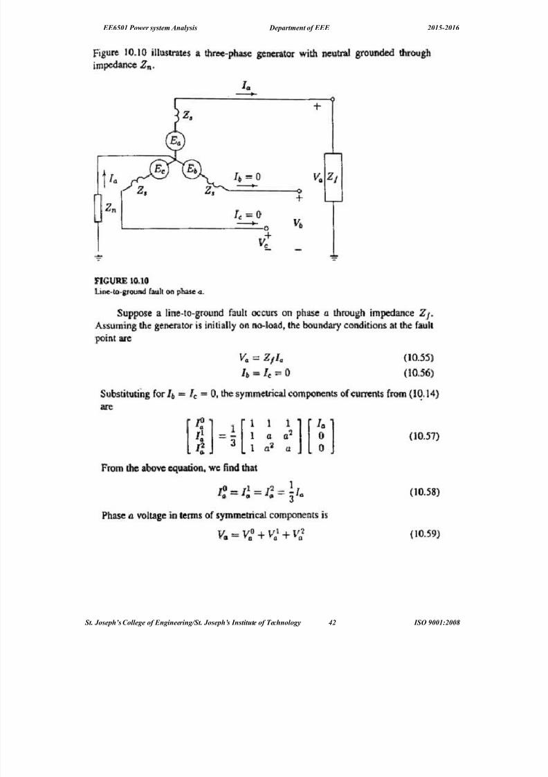
%omponents of oltaes an %#rrents. ii3 Dis%#ss in etail a:o#t the se<#en%e impean%es of
transmission lines.>o 20123 The networ* which is used to represent the positive, negative and Bero sequence components of unbalanced system is called as sequence networ*
St. Joseph’s Collee of Enineerin!St. Joseph’s "nstit#te of $e%hnoloy +) "S& '001(200)
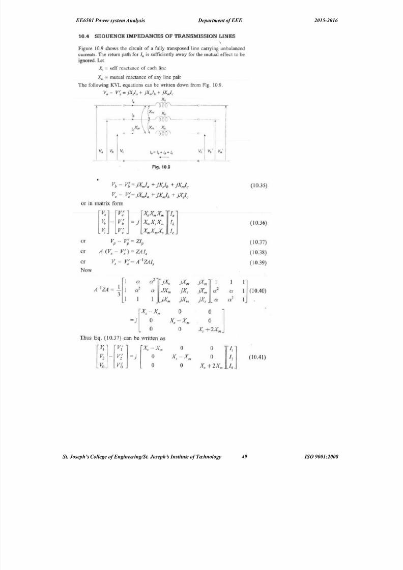
8/18/2019 PSA qb 15-16 with answer.docx
http://slidepdf.com/reader/full/psa-qb-15-16-with-answerdocx 49/75
EE6501 Power system Analysis Department of EEE 2015-2016
St. Joseph’s Collee of Enineerin!St. Joseph’s "nstit#te of $e%hnoloy +' "S& '001(200)

8/18/2019 PSA qb 15-16 with answer.docx
http://slidepdf.com/reader/full/psa-qb-15-16-with-answerdocx 50/75
EE6501 Power system Analysis Department of EEE 2015-2016
14.Aiscuss in detail about the sequence impedances and networ*s of synchronous machines, transmission
lines, transformers and load. ?5a& "41%@Positive6Negative6=ero <e/uene of <&nhronous mahine are
St. Joseph’s Collee of Enineerin!St. Joseph’s "nstit#te of $e%hnoloy 50 "S& '001(200)

8/18/2019 PSA qb 15-16 with answer.docx
http://slidepdf.com/reader/full/psa-qb-15-16-with-answerdocx 51/75
EE6501 Power system Analysis Department of EEE 2015-2016
Positive6Negative6=ero <e/uene of are $oad
St. Joseph’s Collee of Enineerin!St. Joseph’s "nstit#te of $e%hnoloy 51 "S& '001(200)

8/18/2019 PSA qb 15-16 with answer.docx
http://slidepdf.com/reader/full/psa-qb-15-16-with-answerdocx 52/75
EE6501 Power system Analysis Department of EEE 2015-2016
=ero <e/uene of Transformer for L'LB
St. Joseph’s Collee of Enineerin!St. Joseph’s "nstit#te of $e%hnoloy 52 "S& '001(200)

8/18/2019 PSA qb 15-16 with answer.docx
http://slidepdf.com/reader/full/psa-qb-15-16-with-answerdocx 53/75
EE6501 Power system Analysis Department of EEE 2015-2016
15. ( single line diagram of a power networ* is shown in the figure. ?5a& "41%@
The system data is given in the tableas below
:lement Dositive sequencereactance
$egative sequencereactance
@ero sequencereactance
Cenerator C 0.1 0.1 0.02+otor +1 0.02 0.0 0.02+otor + 0.02 0.0 0.02Transformer Tr1 0.04 0.04 0.04Transformer Tr 0.05 0.05 0.05
#ine 0.10 0.10 0.10Cenerator grounding reactance is 0.2 pu. Araw sequence networ*s and calculate the fault for a line toline fault on phase b andc at point D. (ssume 1.0 pu pre fault voltage throughout.Positive <e/uene Net,orMB
St. Joseph’s Collee of Enineerin!St. Joseph’s "nstit#te of $e%hnoloy 5* "S& '001(200)

8/18/2019 PSA qb 15-16 with answer.docx
http://slidepdf.com/reader/full/psa-qb-15-16-with-answerdocx 54/75
EE6501 Power system Analysis Department of EEE 2015-2016
16. The figure shows the power system networ* .Araw Bero sequence networ* for this system. The systemdata is as under.Cenerator C120 +"( ,11 '", F0/ 0.05 pu Transformer T1 20 +"(,110 '", F0/ 0.1puCenerator C &0 +"( ,113G '", F0/ 0.04pu Transformer T J&0 +"( ,110 '" ,F0/ 0.06 pu@ero sequene reactance of line is 222. 7. hoose base +"( 20 and base voltage 11 '" for #T sideand 0 '" for HT side.?Nov "41%@
St. Joseph’s Collee of Enineerin!St. Joseph’s "nstit#te of $e%hnoloy 5+ "S& '001(200)

8/18/2019 PSA qb 15-16 with answer.docx
http://slidepdf.com/reader/full/psa-qb-15-16-with-answerdocx 55/75
EE6501 Power system Analysis Department of EEE 2015-2016
0.( 2 +"( 6 1&. '" alternator with solidly grounded neutral has a sub transient reactance of 0.2 p.u.The negative and Bero sequence reactance are 0.&2 and 0.01 p.u. respectively. If a double linetogroundfault occurs at the terminals of the alternator, determine the fault current and line to line voltage at thefault.?5a& "41*@
<o$utionB<o$utionB>ase 5)A"+5)A6>ase ()1%."()[email protected]=1H4."+ p.u6="H4.%+p.u6=g4H4.1p.un4.1p.u6Ia1 'H"."2p.uIa"H1.""+p.u
Ia4H1.4"p.uI#'%.4*GH1.-4*+I%.4*GH1.-4*+InI#GIH%."4 p.u In*"42A1.<btain the expression for fault current for a line to line fault ta*en place through an impedance @ b in a power system.?Nov "41%@?5a& "41*@
St. Joseph’s Collee of Enineerin!St. Joseph’s "nstit#te of $e%hnoloy 55 "S& '001(200)

8/18/2019 PSA qb 15-16 with answer.docx
http://slidepdf.com/reader/full/psa-qb-15-16-with-answerdocx 56/75
EE6501 Power system Analysis Department of EEE 2015-2016
St. Joseph’s Collee of Enineerin!St. Joseph’s "nstit#te of $e%hnoloy 56 "S& '001(200)

8/18/2019 PSA qb 15-16 with answer.docx
http://slidepdf.com/reader/full/psa-qb-15-16-with-answerdocx 57/75
EE6501 Power system Analysis Department of EEE 2015-2016
"". O#tain the e0pression for fau$t urrent for a $ine to $ine fau$t taMen p$ae through an impedane=# in a po,er s&stem.?Nov "41%@?5a& "41*@
<o$utionIMo4IM1'IM")M?4@F=MM1G=MM"G=#Ia#M IM 41"
"". 0p$ain a#out the onepts of s&mmetria$ omponent. ?Nov "41*@
<et of n un#a$aned vetor an #e onverted to set of n #a$aned vetor usings&mmetria$ omponent Transformation.IaIa4GIa1GIa"
I#I#4GI#1GI#"
II4GI1GI"
"*. A sing$e $ine to ground fau$t ours on >us 1 of the s&stem of the fig. sho,n #e$o,.indi@ Current in the fau$tii@ <C urrent in phase A of generatoriii@ )o$tage of the hea$th& phases of the #us1 using = #us method
St. Joseph’s Collee of Enineerin!St. Joseph’s "nstit#te of $e%hnoloy 5, "S& '001(200)

8/18/2019 PSA qb 15-16 with answer.docx
http://slidepdf.com/reader/full/psa-qb-15-16-with-answerdocx 58/75
EE6501 Power system Analysis Department of EEE 2015-2016
8ivenB Rating of the eah mahine 1"44()A6 -44)6,ith "1476o+7 eah three phasetransformer is rated 1"44 ()A 6 -44)'YF%444)'L ,ith $eaMage reatane of +7 the reatane of the transmission $ine are 1 " "47 and o*47 on the #ase of 1"44 ()A 6%%44)6the
reatane of the neutra$ reators are +7 on the ()A and vo$tage #ase of the mahine. ?Nov"41*@
<o$utionBau$t urrentH1.+2+pu
<C urrent in phase A of generatorH1.2+2pu)o$tage of the hea$th& phases of the #us1)#4.**+pu
)4.+2pu
UNIT–) <TA>I9ITLANA9L<I<PART – A
1. Define D&nami sta#i$it& of a po,er s&stem.Aynamic stability is the stability given to an inherently unstable system by automatic control devices andthis dynamic stability is concerned with small disturbances lasting for times of the order of 10 to &0seconds.". Define the inertia onstants 5 3.(ngular momentum !+% about a fixed axis is defined as the product of moment of inertia about that axisand the associated angular velocity. + / I. ω wattrad8ec.Inertia constant !H% is the '.: in +ega ;oulesto the three phase +"( rating of the machine.
%. Define $oad ang$e of a generator.#oad angle This is the angle between the generated e.m.f or the supply voltage !: % and the terminalvoltage. This angle is also called as torque or power angle of the machine.*. <tate e/ua$ area riterion of sta#i$it&.
The system is stable if the area under accelerating power !Da% δ curve reduces to Bero at some value of δ.In other words positive area under Da δ curve must be equal to the negative area and hence the nameequal area criterion of stability.+. What are $imitations of e/ua$ area riterion!The limitations of equal area criterion are i% one drawbac* of equal area criterion approach is that criticalclearing time cannot be calculated even though the critical clearing angle is *nown. Hence numericalmethods such as Lunge*utta method, point by point or :ulerWs method are employed.ii% ItWs a more simplified approach.
-. If t,o mahines ,ith inertias 3 16 3" are s,inging together6 ,hat ,i$$ #e the inertia of thee/uiva$ent mahine!
! s= !
1-
1+ !
2-
2
-s
H1 and H is the Inertia constant of +1 and +J C1 and C is the capacity of +1 and +.Hs is the equivalent inertia of +1 and + J Cs is the equivalent capacity of +1 and +.. On ,hat #asis do &ou on$ude that the given s&nhronous mahine has $ost sta#i$it&!=ollowing a sudden disturbance on a power system rotor speeds, rotor angular differences and power transfer undergo fast changes whose magnitude is dependent on the severity of the disturbance. If thesedisturbances leads to growing oscillations in the power system even after some period of time say morethan &0 seconds then system said are in asynchronous state and it has lost synchronism.
St. Joseph’s Collee of Enineerin!St. Joseph’s "nstit#te of $e%hnoloy 5) "S& '001(200)

8/18/2019 PSA qb 15-16 with answer.docx
http://slidepdf.com/reader/full/psa-qb-15-16-with-answerdocx 59/75
EE6501 Power system Analysis Department of EEE 2015-2016
. On ,hat a fator does the ritia$ $earing ang$e depends.The critical clearing angle depends upon the clearing time, which depends upon auto closingreclosingand opening of circuit brea*ers.2. Define stead& state sta#i$it& $imit. ?Nov "41*@It is the maximum power that can be transferred without the system becoming unstable when the systemis sub;ected to small disturbances.14. 5ention methods of improving the stead& state sta#i$it& $imit.Dmax / ! :." F %. The steady state stability limit can be increased by i% Leducing the F, in case of transmission lines by using double circuit lines. ii% ?se of series capacitors to get better voltage. iii%Higher excitation systems and quic* excitation system are employed.11. A +43V6 * po$e tur#o a$ternator rated at "4 5)A6 1%." () has as inertia onstant 3 * (W –
seF ()A. ind the (. stored in the rotor at s&nhronous speed.= / 20HB. D / 3, C / 0 +"(, H / 3 '> P 8ec '"(. 8tored '.: / 3 x 0 / 50+U.1". 5ention the methods used for the so$ution of s,ing e/uation.+ethods used for solution of swing equation are Doint by point method, +odified :ulerWs method andLunge*utta method.1%. 8ive methods used for improving the transient sta#i$it&.The following methods are employed to increase the transient stability limit of the power system!i%Increase of system voltages,!ii% use of ("L.!iii%?se of High speed excitation systems.!iv%Leduction intransfer reactance.!v%?seof high speed reclosing brea*ers.1*. Define the term s&nhroniVing po,er oeffiient of a s&nhronous mahine!
The rate!dpdδ%, ie, the differential power increase obtained per differential load angle increase is calledthe synchroniBing power coefficient or electrical stiffness of a synchronous machine.1+. What are the app$iations of e/ua$ area riterion!!i%8witching operation. !ii%=ault and subsequent circuit isolation. !iii% =ault, circuit isolation and reclosing1-. What are the $assifiations of ang$e sta#i$it&!8mall signal stability !steady state% and transient stability !large signal%.8mall signal is further classifiedas <scillatory and $on oscillatory stability.<scillatory includes Inter area mode, control mode andTorsional mode1. Define ritia$ $earing ang$e and time! ?5a& "411@?5a& "41"@?Nov "41"@ ?Nov "41*@
ritical clearing angle Yδc Wcorresponds to critical clearing timetc,in which the fault in the line is cleared
by the circuit brea*er above which the system goes out of synchronism.1. Write s,ing e/uation ?5a& "411@
DmDe/ +dSdt. Dm Input +echanical power De P output electrical powerJ + (ngular momentum12. Define transient sta#i$it& and sta#i$it& $imit. ?5a& "41"@The maximum power that can be transferred through the system during a very large disturbance withoutloss of synchronism is called transient stability limit."4. Distinguish #et,een stead& state and transient state sta#i$it&. ?Nov "41"@8teady state stability is basically concerned with the ability of the system to restore bac* to its stable stateupon a small disturbance whereas the transient stability is concerned with large disturbances."1. What is meant #& po,er ang$e urve! ?5a& "41%@The graphical plot of real power versus powertorque angle is called as power angle curve.
De / Dm sin δ. Dm / :1: F.
"". Define Infinite #us in po,er s&stem. ?Nov "41"@?5a& "41%@The capacity of a system comprising of many machines is so large, that its voltage Q frequency may be ta*en as constant. The connection or disconnection of a single machine does not change the V"V andfrequency. 8uch a constant voltage and frequency system is called as Infinite bus."%. Differentiate #et,een vo$tage sta#i$it& and rotor ang$e sta#i$it&. ?Nov "41%@"oltage stability is the ability of a power system to maintain steady acceptable voltage at all buses in thesystem under normal operating conditions and after being sub;ected to a disturbance.Lotor angle stability is the ability of interconnected synchronous machines of a power system to remainin synchronism."*. Define s,ing urve! What is the use of this urve! ?Nov "41%@
St. Joseph’s Collee of Enineerin!St. Joseph’s "nstit#te of $e%hnoloy 5' "S& '001(200)

8/18/2019 PSA qb 15-16 with answer.docx
http://slidepdf.com/reader/full/psa-qb-15-16-with-answerdocx 60/75
EE6501 Power system Analysis Department of EEE 2015-2016
( graph of δ versus time in seconds is called swing curve. The stability of the machine is calculated byusing swing curve. This curve is obtained by solving the swing equation of the machine. The critical angleand critical clearing time is calculated by using swing curve."+. Define d&nami sta#i$it& ?5a& "41*@The dynamic stability study is concerned with the study of nature of oscillations and its decay for smalldisturbances."-. ind the fre/uen& of osi$$ation for a s&nhroniVing o'effiient of 4.-6 inertia onstant 3 *
and s&stem fre/uen& of +4 3V.?5a& "41*@=requency of oscillation / √ .
M J M =
!
/( =
4
/ X 50=0.0255 p ) u
=requency of oscillation / √ 0.6
0.0255=4.85
rad
sec=
4.85
2 / =0.7719 !0
PART >
1. ( 20HB generator is supplying 0E of Dmax to an infinite bus through a reactive networ*. ( faultoccurs which increases the reactanceWs of the networ* between the generator internal voltage andinfinite bus by 300E. >hen the fault is cleared, compute the max value of critical clearing angle byapplying equal area criteria.
<o$utionBPrefau$t ConditionB
Pe1=| & ||V | X 12
sinδ 0
δ 0=¿ sin'14.+4.+"* rad
During au$tB
Pe"4."Pma01sinQPost au$tB
Pe%4.+Pma01sinQPm4.+
Qma0".*1" radCosQr4.%+
Qr1.1-rad -.%+o
2.State the :a effe%ts of insta:ility. Distin#ish :etween steay state an transient state sta:ilities.
The 8ynchronism of the system gets affected.8teady state stability is basically concerned with the ability of the system to restore bac* to itsstable state upon a small disturbance whereas the transient stability is concerned with largedisturbances.
&. Two power stations ( Q ) are located close together. 8tation ( has 3 identical generator sets each rated100+"( and having an inertia constant of 6 +U +"(, whereas station ) has three sets each rated00+"( , 3 +U +"(. alculate the inertia constant of single equivalent machines on a base of 100+"(.
<o$utionB
! e1= !
1,*ac'+1,*ac'
+s2s+ !
2, *ac'+2,*ac'
+s2s
At <tation 'A B 3A%- 5F5)AAt <tation –>B 3>"*5F5)A3e/ 3AG 3>%-G"*-45F5)A
St. Joseph’s Collee of Enineerin!St. Joseph’s "nstit#te of $e%hnoloy 60 "S& '001(200)

8/18/2019 PSA qb 15-16 with answer.docx
http://slidepdf.com/reader/full/psa-qb-15-16-with-answerdocx 61/75
EE6501 Power system Analysis Department of EEE 2015-2016
*. 0p$ain the u$ers method of so$ving the sta#i$it& pro#$em.3. ( 20 HB 3 pole turbo alternator rated 0 +"(, 1&. '" has an inertia constant of H / 6'>sec'"(.
Aetermine the '.: stored in the rotor at sync speed. Aetermine the acceleration if the input is less, therotational losses is 0000 HD and electric power delivered is 12000'>. If the acceleration computedfor the generator is constant for a period of 12 cycles, Aetermine the change in torque angle in that period and the r.p.m at the end of 12 cycles. (ssume that the generator is synchroniBed with a largesystem and has no accelerating torque when 12 cycleperiod begins.
<o$utionB(ineti energ& stored in the rotor is 145The ae$eration po,er Pa%.%+ 5WThe ae$erion S1-.+ e$e degFse"
T4.%seChange in Q4.+ZSZT".+2% e$e.degree<&nhronus speed Ns1+44 rpmRotor speed in rpm NsGSF-4 1+4".1 rpm2. ( motor is receiving 2E of the power that it is capable of receiving from an infinite bus. Ifthe load on
the motor is doubled. alculate the max value of δ during the swinging of the rotor around its newequilibrium position.
<o$utionB P
e1
= P*a3
sinδ 0
sinδ 0=
Pe
P*a3
=50
sinδ 0=0.5
δ 0=300
δ *a3=/ −δ 0=/ −30=150=2.617 rad
.Aescribe the Lunge'utta method of solution of swing equation for multi machine systems.?5a& "411@
St. Joseph’s Collee of Enineerin!St. Joseph’s "nstit#te of $e%hnoloy 61 "S& '001(200)

8/18/2019 PSA qb 15-16 with answer.docx
http://slidepdf.com/reader/full/psa-qb-15-16-with-answerdocx 62/75
EE6501 Power system Analysis Department of EEE 2015-2016
4.( & phase generator delivers1.0 pu power to an infinite bus through a transmission networ* when faultoccurs. The maximum power which can be transferred during prefault, during fault and post faultcondition are 1.42pu, 0.3pu and 1.2 pu.=ind the critical clearing angle.?5a& "41"@<o$utionB
Pm1.4 p.u
P*a3=1.75 p ) u P*= P*a3 sinδ
0
sin δ 0= Pe
P*a3
δ 0=34.850
δ *a3=127.87o
cosδ c=0.621
δ c=51.6o
?5a& "411@
St. Joseph’s Collee of Enineerin!St. Joseph’s "nstit#te of $e%hnoloy 62 "S& '001(200)

8/18/2019 PSA qb 15-16 with answer.docx
http://slidepdf.com/reader/full/psa-qb-15-16-with-answerdocx 63/75
EE6501 Power system Analysis Department of EEE 2015-2016
. Derive the Po,er ang$e e/uation for a i@ <5I> s&stem and a$so dra, the po,er ang$e urve.?5a& "41"@
Pe1=| & ||V | X 12
sinδ 0
ii@ A generator having d4.pu de$ivers po,er at po,er fator of 4. 9agging. Determine
Pe6e6 and Q .
Data missing
Using /ua$ area riterion derive an e0pression for ritia$ $earing ang$e for a s&stem having agenerator feeding a $arge s&stem through a dou#$e iruit $ine. ?5a& "41"@ ?Nov "41*@
5. !a% 8tate and explain the equal area criterion. !b% Indicate how you will apply equal area criterion.!i% Tofind the max additional load that can be suddenly added. !ii% In a two circuit transmission systemsudden loss of one circuit.?Nov "41"@ ?5a& "41%@ ?5a& "41"@
St. Joseph’s Collee of Enineerin!St. Joseph’s "nstit#te of $e%hnoloy 6* "S& '001(200)

8/18/2019 PSA qb 15-16 with answer.docx
http://slidepdf.com/reader/full/psa-qb-15-16-with-answerdocx 64/75
EE6501 Power system Analysis Department of EEE 2015-2016
St. Joseph’s Collee of Enineerin!St. Joseph’s "nstit#te of $e%hnoloy 6+ "S& '001(200)

8/18/2019 PSA qb 15-16 with answer.docx
http://slidepdf.com/reader/full/psa-qb-15-16-with-answerdocx 65/75
EE6501 Power system Analysis Department of EEE 2015-2016
St. Joseph’s Collee of Enineerin!St. Joseph’s "nstit#te of $e%hnoloy 65 "S& '001(200)

8/18/2019 PSA qb 15-16 with answer.docx
http://slidepdf.com/reader/full/psa-qb-15-16-with-answerdocx 66/75
EE6501 Power system Analysis Department of EEE 2015-2016
St. Joseph’s Collee of Enineerin!St. Joseph’s "nstit#te of $e%hnoloy 66 "S& '001(200)

8/18/2019 PSA qb 15-16 with answer.docx
http://slidepdf.com/reader/full/psa-qb-15-16-with-answerdocx 67/75
EE6501 Power system Analysis Department of EEE 2015-2016
6. Aerive the swing equation of a synchronous machine swinging against an infinite bus. learly state theassumptions made in deducing the swing equation. 8tate the usefulness of this equation. 8tate thereasons for its nonlinearity ?5a& "41%@ .?5a& "41*@
St. Joseph’s Collee of Enineerin!St. Joseph’s "nstit#te of $e%hnoloy 6, "S& '001(200)

8/18/2019 PSA qb 15-16 with answer.docx
http://slidepdf.com/reader/full/psa-qb-15-16-with-answerdocx 68/75
EE6501 Power system Analysis Department of EEE 2015-2016
St. Joseph’s Collee of Enineerin!St. Joseph’s "nstit#te of $e%hnoloy 6) "S& '001(200)

8/18/2019 PSA qb 15-16 with answer.docx
http://slidepdf.com/reader/full/psa-qb-15-16-with-answerdocx 69/75
EE6501 Power system Analysis Department of EEE 2015-2016
St. Joseph’s Collee of Enineerin!St. Joseph’s "nstit#te of $e%hnoloy 6' "S& '001(200)
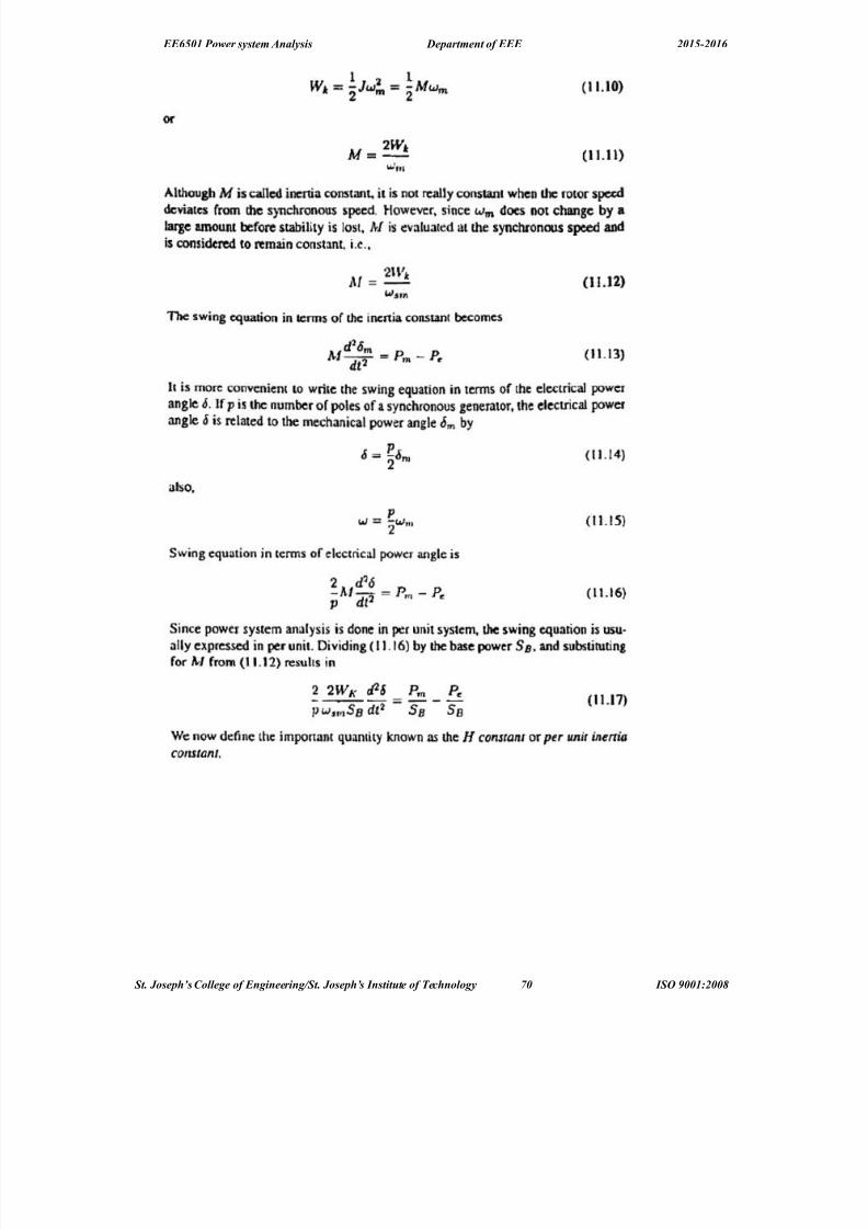
8/18/2019 PSA qb 15-16 with answer.docx
http://slidepdf.com/reader/full/psa-qb-15-16-with-answerdocx 70/75
EE6501 Power system Analysis Department of EEE 2015-2016
St. Joseph’s Collee of Enineerin!St. Joseph’s "nstit#te of $e%hnoloy ,0 "S& '001(200)
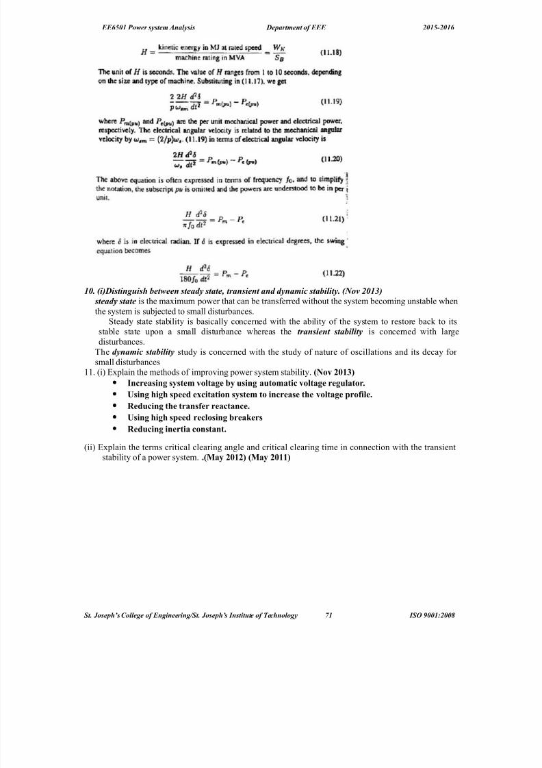
8/18/2019 PSA qb 15-16 with answer.docx
http://slidepdf.com/reader/full/psa-qb-15-16-with-answerdocx 71/75
EE6501 Power system Analysis Department of EEE 2015-2016
10. i3Distin#ish :etween steay state? transient an ynami% sta:ility. >o 201*3
steay state is the maximum power that can be transferred without the system becoming unstable whenthe system is sub;ected to small disturbances. 8teady state stability is basically concerned with the ability of the system to restore bac* to itsstable state upon a small disturbance whereas the transient sta:ility is concerned with largedisturbances.
The ynami% sta:ility study is concerned with the study of nature of oscillations and its decay for small disturbances
11. !i% :xplain the methods of improving power system stability. ?Nov "41%@
Inreasing s&stem vo$tage #& using automati vo$tage regu$ator.
Using high speed e0itation s&stem to inrease the vo$tage profi$e.
Reduing the transfer reatane.
Using high speed re$osing #reaMers
Reduing inertia onstant.
!ii% :xplain the terms critical clearing angle and critical clearing time in connection with the transientstability of a power system. .?5a& "41"@ ?5a& "411@
St. Joseph’s Collee of Enineerin!St. Joseph’s "nstit#te of $e%hnoloy ,1 "S& '001(200)
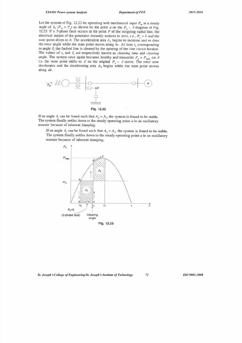
8/18/2019 PSA qb 15-16 with answer.docx
http://slidepdf.com/reader/full/psa-qb-15-16-with-answerdocx 72/75
EE6501 Power system Analysis Department of EEE 2015-2016
St. Joseph’s Collee of Enineerin!St. Joseph’s "nstit#te of $e%hnoloy ,2 "S& '001(200)
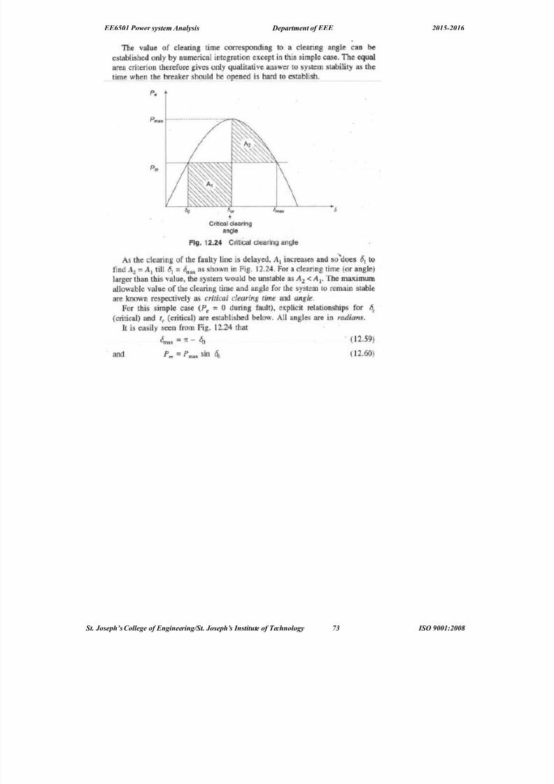
8/18/2019 PSA qb 15-16 with answer.docx
http://slidepdf.com/reader/full/psa-qb-15-16-with-answerdocx 73/75
EE6501 Power system Analysis Department of EEE 2015-2016
St. Joseph’s Collee of Enineerin!St. Joseph’s "nstit#te of $e%hnoloy ,* "S& '001(200)

8/18/2019 PSA qb 15-16 with answer.docx
http://slidepdf.com/reader/full/psa-qb-15-16-with-answerdocx 74/75
EE6501 Power system Analysis Department of EEE 2015-2016
1. Aescribe the algorithm for modified :uler method of finding solution for power system stability problem studies.?Nov "41"@?5a& "41*@
St. Joseph’s Collee of Enineerin!St. Joseph’s "nstit#te of $e%hnoloy ,+ "S& '001(200)

8/18/2019 PSA qb 15-16 with answer.docx
http://slidepdf.com/reader/full/psa-qb-15-16-with-answerdocx 75/75
EE6501 Power system Analysis Department of EEE 2015-2016