psoc® 3 and psoc 5 interrupts - an54460 - texas a&m...
TRANSCRIPT

www.cypress.com Document No. 001-54460 Rev. *D 1
AN54460 PSoC® 3 and PSoC 5 Interrupts
Author: Vivek Shankar Kannan Associated Project: Yes
Associated Part Family: All PSoC® 3 and PSoC 5 families Software Version: PSoC Creator™ 2.0
Related Application Notes: AN60630
If you have a question, or need help with this application note, contact the author at [email protected].
AN54460 explains the interrupt architecture in PSoC® 3 and PSoC 5 and the support for interrupts in the PSoC Creator™ IDE. Advanced interrupt concepts such as handling re-entrant functions and optimizing the interrupt code are explained in detail. After reading this application note, you will be able to use PSoC 3 and PSoC 5 interrupts in an efficient way for different applications.
Contents Introduction ....................................................................... 1 PSoC 3 and PSoC 5 Interrupt Architecture ....................... 1
Unique Features of PSoC 3 and PSoC 5 Interrupts ..... 2 Level and Edge Triggered Interrupts ............................ 2 PSoC 3 and PSoC 5 Interrupt Sources ........................ 3
Interrupt Support in PSoC Creator .................................... 3 Interrupt Component Configuration .............................. 4 Interrupt Priority Configuration ...................................... 5 My First Interrupt Project .............................................. 5 Changing Interrupt Vector Address .............................. 7
Re-entrant Functions in PSoC 3 ........................................ 8 Re-entrancy in Keil C51 Compiler ................................ 8 Re-entrancy Support in PSoC Creator ......................... 8 Determining Re-entrant Functions ................................ 9 PICU Interrupt Project ................................................ 10
Advanced Interrupt Topics .............................................. 12 Optimizing the Interrupt Code ..................................... 12 Interrupt Component APIs .......................................... 12 Interrupts and Other Components .............................. 13 Unsupported Fixed Function Interrupts ...................... 13 Forcing Interrupt Vector Number Selection ................ 14
Summary ......................................................................... 15 Project Summary ........................................................ 15
Appendix A – Interrupt Sources in PSoC 3 and PSoC 5 . 16 Worldwide Sales and Design Support ............................. 19
Introduction Interrupts are an important part of any embedded application. They free the CPU from having to continuously poll the occurrence of a specific event and, instead, notify the CPU only when that event occurs. In system-on-chip (SoC) architectures, such as PSoC 3 and PSoC 5, interrupts are frequently used to communicate the status of the different on-chip peripherals to the CPU.
AN54460 introduces you to the PSoC 3 and PSoC 5 interrupt architecture, and explains the support for interrupts in the PSoC Creator IDE, the development tool for PSoC 3 and PSoC 5. Advanced interrupt concepts such as handling re-entrant functions are explained in detail. Code examples are provided to explain the different use cases of interrupts.
PSoC 3 and PSoC 5 Interrupt Architecture This section gives an overview of the PSoC 3 and PSoC 5 interrupt architecture.
Figure 1. PSoC 3 and PSoC 5 Interrupt Architecture
InterruptController
int[0]int[1]
int[31]
CPU
Interrupt Lines
PSoC® 3 and PSoC 5 Interrupts
www.cypress.com Document No. 001-54460 Rev. *D 2
Figure 1 shows the simplified view of the PSoC 3 and PSoC /5 interrupt architecture. There are 32 interrupt lines (int[0…31]) in PSoC 3 and PSoC 5. Each interrupt line can be assigned one of the eight priority levels (0-7), with ‘0’ being the highest priority and ‘7’ being the lowest priority. Each interrupt line is assigned an interrupt vector address, which refers to the starting address of the interrupt code. The CPU execution branches to this address after receiving an interrupt request. The interrupt code is referred to as the Interrupt Service Routine (ISR).
The interrupt controller acts as the interface between the interrupt lines and the CPU. It sends the interrupt vector address of an interrupt line to the CPU along with the interrupt request signal. The interrupt controller also receives acknowledgement signals from the CPU on interrupt entry and exit conditions. The interrupt controller resolves interrupt priority in the case of requests from multiple interrupt lines.
For more technical information on the operation of PSoC 3 and PSoC 5 interrupts, refer to the Interrupt Controller chapter of the PSoC 3 Technical Reference Manual (TRM), PSoC 5 TRM.
Unique Features of PSoC 3 and PSoC 5 Interrupts PSoC 3 and PSoC 5 provide the following enhanced interrupt features that are not supported by the other traditional microcontrollers:
Configurable Interrupt Vector Address: In PSoC 3 and PSOC 5, you can dynamically configure the interrupt vector address. The CPU execution can be directly branched to any ISR code when the interrupt occurs. In traditional microcontrollers, the interrupt vector address is fixed for each interrupt line. Typically, a “JUMP” instruction is placed in that fixed address to branch the CPU execution to the actual ISR code. This unique feature reduces the interrupt execution latency in PSoC 3 and PSoC 5 compared to the traditional microcontrollers.
Flexible Interrupt Sources: In traditional microcontrollers, the interrupt source is fixed for each interrupt line. PSoC 3 and PSoC 5, give you the flexibility to choose the interrupt source for each interrupt line. This flexible architecture enables any digital signal to be configured as an interrupt source.
Level and Edge Triggered Interrupts PSoC 3 and PSoC 5 support both level triggered and edge triggered interrupts. The classification of an interrupt as level or edge triggered is based on the interrupt signal generated by the interrupt source.
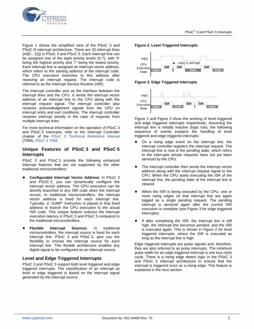
Figure 2. Level Triggered Interrupts
int[x]
CPU Execution
State mainISR ISR
mainISR
main
int[x] is still high
Figure 3. Edge Triggered Interrupts
int[x]
CPU Execution
State mainISR
mainISR
mainISR
Figure 2 and Figure 3 show the working of level triggered and edge triggered interrupts respectively. Assuming the interrupt line is initially inactive (logic low), the following sequence of events explains the handling of level triggered and edge triggered interrupts:
On a rising edge event on the interrupt line, the interrupt controller registers the interrupt request. The interrupt line is now in the pending state, which refers to the interrupts whose requests have not yet been serviced by the CPU.
The interrupt controller then sends the interrupt vector address along with the interrupt request signal to the CPU. When the CPU starts executing the ISR of the interrupt line, the pending state of the interrupt line is cleared.
When the ISR is being executed by the CPU, one or more rising edges on that interrupt line are again logged as a single pending request. The pending interrupt is serviced again after the current ISR execution is complete (see Figure 3 for edge triggered interrupts).
If after completing the ISR, the interrupt line is still high, the interrupt line becomes pended, and the ISR is executed again. This is shown in Figure 2 for level triggered interrupts, where the ISR is executed as long as the interrupt line is high.
Edge triggered interrupts are pulse signals and, therefore, they are also referred to as pulse interrupts. The minimum pulse width for an edge triggered interrupt is one bus clock cycle. There is a rising edge detect logic in the PSoC 3 and PSoC 5 interrupt architecture to ensure that the interrupt is triggered once on a rising edge. This feature is explained in the next section.

PSoC® 3 and PSoC 5 Interrupts
www.cypress.com Document No. 001-54460 Rev. *D 3
PSoC 3 and PSoC 5 Interrupt Sources Figure 4. Interrupt Sources in PSoC 3/5
DMA nrq Interrupt Source
Fixed Function Interrupt Source
Rising Edge Detect
UDB Interrupt Source
DigitalSystem
Interconnect
0
1
2
3
int[n]
IDMUX
n = 0 to 31
Direct Path To Interrupt Controller
Each of the interrupt lines (int[0…31]) in PSoC 3 and PSoC 5 can be driven by one of the three interrupt sources as shown in Figure 4. There is a multiplexer logic (IDMUX) to select the source for each interrupt line.
Fixed Funct ion Interrupt Sources These are the predefined set of interrupt sources from the different on-chip peripherals. Examples of these include the interrupt signals from the fixed function timers, counters, Port Interrupt Control Unit (PICU), and so on. The list of fixed function interrupt sources in PSoC 3 and PSoC 5 is provided in Appendix A – Interrupt Sources in PSoC 3 and PSoC 5.
Most of the fixed function interrupt sources are level interrupts that require the peripheral status register to be read in the ISR. There are two purposes for reading the peripheral status register in the ISR:
1. Reading the status register gives the knowledge of what peripheral condition generated the interrupt. For example, in the case of a PICU interrupt, each bit of the PICU status register corresponds to a port pin. Reading the status register will let the user know which port pin(s) generated the PICU interrupt.
2. The interrupt source is derived as logical OR signal of the status register bits. The bits that are set in the status register will be cleared on a CPU read operation, thus bringing the interrupt line low. If the status register is not read in the ISR, the ISR will be executed continuously.
DMA nrq Interrupt Source Each direct memory access (DMA) channel in PSoC 3 and PSoC 5 generates a pulse signal on the completion of a DMA transfer operation. This transfer complete signal (referred to as the nrq signal) can be used to trigger an interrupt after the DMA data transfer is complete. This is an edge triggered interrupt.
UDB Interrupt Sources Any digital signal can be configured as an interrupt source by routing it through the digital system interconnect (DSI). These sources are broadly referred to as UDB interrupt sources because most of these interrupt sources are from the universal digital blocks (UDBs) in PSoC 3 and PSoC 5.
UDB is the basic building block of the different digital peripherals in PSoC 3 and PSoC 5. Examples are the digital peripherals such as UART, SPI, I2C, and UDB-based timers, counters, and PWMs.
The fixed function interrupt sources can also be routed through the DSI interface apart from the dedicated routes available for them as shown in Figure 4.
There are two paths that exist for the UDB interrupt sources.
1. The first path is a direct connection of the UDB interrupt source to the interrupt line, which is marked as Direct Path in Figure 4. This is used for level triggered UDB interrupts. Examples are the interrupts generated by the communication peripherals like UART and SPI that generate level interrupts to indicate that the First In First Out (FIFO) data buffer has data to be read (Receive FIFO) or space for data to be written (Transmit FIFO).
2. The second option is to pass the UDB interrupt source through the Rising Edge Detect logic as shown in Figure 4.
Figure 5. Edge Triggered UDB Interrupt Source
int[x](Output of “Rising
Edge Detect”)
CPU Execution State
mainISR
main main
1 bus clock
Interrupt Source
ISR
In this case, the occurrence of a rising edge signal from the UDB interrupt source is converted into a pulse signal as shown in Figure 5. This feature is used for interrupt sources that should be edge triggered.
Now that you have learnt the interrupt features supported in PSoC 3 and PSoC 5, the following sections explain how the PSoC Creator IDE simplifies the use of interrupts and the various features available in PSoC Creator for interrupt usage.
Interrupt Support in PSoC Creator PSoC Creator supports interrupts by providing them as a component. The Interrupt component is available under the System tab in the Component Catalog window as shown in Figure 6. Each instance of the interrupt component is an interrupt line. The interrupt source should be connected to the interrupt component in the schematic of the example as shown in Figure 6.

PSoC® 3 and PSoC 5 Interrupts
www.cypress.com Document No. 001-54460 Rev. *D 4
Figure 6. Interrupt Component in PSoC Creator
Interrupt Component Configuration The interrupt component configuration window is shown in Figure 7. The InterruptType parameter in the component is used to configure the IDMUX selection for the interrupt source as shown in Figure 4.
Figure 7. Interrupt Component Configuration
The IDMUX selection criterion is as follows.
InterruptType = Derived: When the Derived option is selected, PSoC Creator makes the IDMUX selection based on the type of the interrupt source:
For digital output signals from the fixed function blocks listed in Table 1, the interrupt source is directly connected to the interrupt controller. Either the dedicated connection for the interrupt source or the direct path through the DSI interface is used.
If the interrupt source is the DMA nrq signal, the dedicated path for the DMA nrq interrupt source is selected.
For any other interrupt source such as the UDB based components, other digital signals, the rising edge option of the DSI interface is selected. The Derived option treats these interrupt sources as edge triggered interrupts.
InterruptType = RISING_EDGE: This selection routes the interrupt source signal through the rising edge detect path as shown in Figure 4. This selection should be made for interrupt sources that you want to be edge triggered.
InterruptType = LEVEL: This option routes the interrupt source through the direct path in the DSI interface. This selection should be made for the interrupts that you want to be level triggered. Examples of the interrupt sources that use this option are the interrupt outputs from the UDB based components like UART, SPI, UDB based timer, counter, and PWM.
Guidel ines for the Interrupt Type Parameter Select ion
For interrupt outputs from the fixed function interrupt sources, and DMA nrq interrupt sources, select the Derived option. The list of PSoC Creator components whose interrupts come under the fixed function category are listed in Appendix A – Interrupt Sources in PSoC 3 and PSoC 5. All the fixed function components have an associated interrupt terminal which will be connected to the interrupt component. If some other digital output signal coming from the fixed function blocks (like the terminal count signal of fixed function timer block) is connected to an interrupt component, do not use the Derived option. Explicitly choose either one of Level or Rising_Edge option as required.
For any other interrupt source, select the Level option if the interrupt should be level triggered, or the Rising_Edge option if the interrupt should be edge triggered. Refer to the respective component datasheet to know the type of interrupt signal generated by the component, and make the selection accordingly.
The Derived option or the Rising_Edge option should never be selected for the interrupts generated by the UDB based components such as UART, SPI, and so on. The reason is that these components generate a level interrupt to indicate the FIFO buffer status signal. The FIFO buffer, which is 4-byte deep, is used to temporarily store data to be transmitted (Tx FIFO) from or received (Rx FIFO) by PSoC 3 and PSoC 5.
For an Rx FIFO, the FIFO status signal is high as long as there is a byte of data to be read by the CPU. Therefore, if
PSoC® 3 and PSoC 5 Interrupts
www.cypress.com Document No. 001-54460 Rev. *D 5
the ISR is written such that only one byte is read each time the interrupt occurs, then selecting the Derived or the Rising_Edge option results in the ISR getting triggered only once on rising edge, even if more than 1 byte is received. This results in the FIFO buffer being overwritten due to the stalled condition of the interrupt. You should consider the implications of configuring a level triggered UDB interrupt source as an edge triggered interrupt before choosing the Derived or the Rising_Edge option.
Interrupt Priority Configuration The design wide resources window (project_name.cydwr) of the project has an Interrupts tab, which displays the interrupt component names, their priority, and vector numbers (line numbers) as shown in Figure 8.
Figure 8. Interrupt Tab in cydwr Window
The priority of the interrupts can be changed in the cydwr window. Remember that 0 has the highest priority, and 7, the lowest priority. The interrupt vector number for each interrupt component is automatically allocated by PSoC Creator when the project is built.
My First Interrupt Project This section guides you through the step by step procedure for creating a simple interrupt based project in PSoC Creator.
The objective of this code example is to toggle a pin when the terminal count of a timer occurs. The timer block in PSoC 3 and PSoC 5 is a down counter, and the terminal count refers to the condition when the timer has reached the minimum value (zero). On the terminal count, the timer is reloaded with the period value and the down counting starts again. An interrupt can be generated every time the terminal count condition occurs.
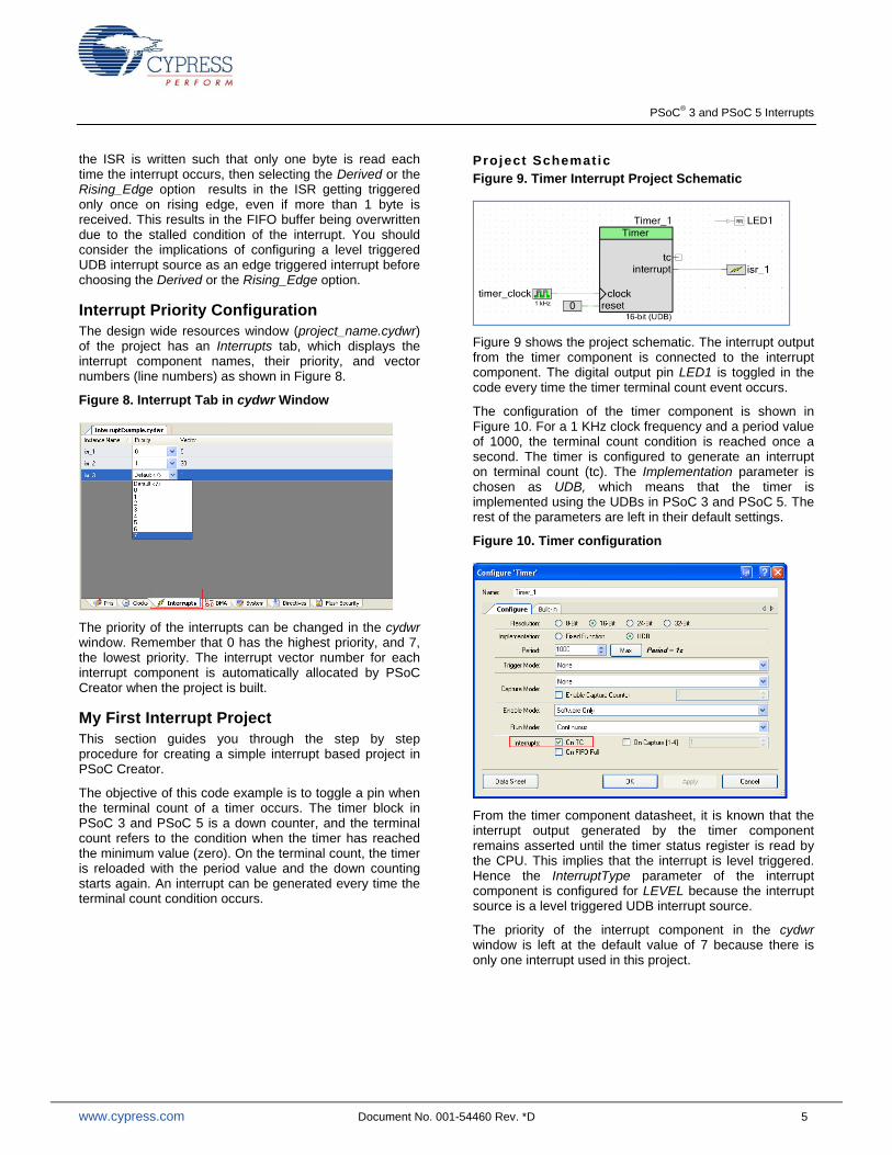
Project Schematic Figure 9. Timer Interrupt Project Schematic
Figure 9 shows the project schematic. The interrupt output from the timer component is connected to the interrupt component. The digital output pin LED1 is toggled in the code every time the timer terminal count event occurs.
The configuration of the timer component is shown in Figure 10. For a 1 KHz clock frequency and a period value of 1000, the terminal count condition is reached once a second. The timer is configured to generate an interrupt on terminal count (tc). The Implementation parameter is chosen as UDB, which means that the timer is implemented using the UDBs in PSoC 3 and PSoC 5. The rest of the parameters are left in their default settings.
Figure 10. Timer configuration
From the timer component datasheet, it is known that the interrupt output generated by the timer component remains asserted until the timer status register is read by the CPU. This implies that the interrupt is level triggered. Hence the InterruptType parameter of the interrupt component is configured for LEVEL because the interrupt source is a level triggered UDB interrupt source.
The priority of the interrupt component in the cydwr window is left at the default value of 7 because there is only one interrupt used in this project.

PSoC® 3 and PSoC 5 Interrupts
www.cypress.com Document No. 001-54460 Rev. *D 6
Writ ing the Interrupt Service Routine Go to Build > Generate Application. PSoC Creator generates the source files and header files for the components used in the project.
PSoC Creator generates a default interrupt service routine (ISR) for each interrupt component in the corresponding source file. This ISR has the name CY_ISR(isr_name). You must write the ISR code in the placeholder inside the function CY_ISR(isr_name).
In this project, a global variable is set in the ISR. This variable is checked in the main code to check if the interrupt has occurred. The global variable should be defined in the ISR source file. The timer component status register is also read in the ISR to bring the interrupt line low. The header file that has the function declaration for reading the timer status register should be included in the ISR source file.
PSoC Creator provides a region in the beginning of the interrupt source file for including the header files, defining the global variables that are used in the ISR code. For the current project, this region has the following code.
Code 1. Including header file and global variables in the ISR
/****************************************** * Place your includes, defines and code here ******************************************/ /* `#START isr_1_intc` */ /* Timer component header file */ #include “Timer_1.h” /* Global variable definition */ volatile uint8 toggle_flag = 0; /* `#END` */ The code should be written only between the #START and #END lines. PSoC Creator preserves only the code written between these two lines during the build process. Any code that is written outside of these two lines is deleted during the build process.
The ISR code for this project follows. It is written in the placeholder region provided inside the function CY_ISR(…).
Code 2. ISR code for the Timer project
CY_ISR(isr_1_Interrupt) { /* Place your Interrupt code here */ /* `#START isr_1_Interrupt` */ /* Read Timer status register to bring the interrupt line low */ Timer_1_ReadStatusRegister(); /* Set the flag variable */ toggle_flag = 1; /* `#END` */ }
The ISR code should be written only between the #START and #END lines. PSoC Creator preserves only the code written between these two lines during the build process.
Complet ing the Main Code In the main code, the components are initialized and started. If the timer interrupt occurs, the output pin is toggled in the main code by checking the global variable that is set in the ISR. The main code for this project follows.
Code 3. Main code for the timer project
#include <device.h> /* Global variable defined in timer ISR */ extern volatile uint8 toggle_flag;
void main() { /* Enable global interrupts */ CYGlobalIntEnable; // Initialize, enable interrupt, timer isr_1_Start(); Timer_1_Start(); for(;;) { /* Toggle the LED1 pin, reset the flag variable */ if(toggle_flag == 1) { LED1_Write(~LED1_Read()); toggle_flag = 0; } } }
In the above code, the macro CYGlobalIntEnable configures the interrupt controller block to generate the interrupt request signal to the CPU, and also configures the CPU to accept the request signals. CYGlobalIntEnable macro is defined in the file CyLib.h, and it takes the appropriate definition based on whether the project is for PSoC 3 or PSoC 5. Using this macro for enabling global interrupts ensures the code portability across multiple compiler tool chains and device families (PSoC 3 and PSoC 5).
The isr_1_Start() function is called in the main code for initializing and enabling the isr_1 interrupt component. This function does the following:
Sets the interrupt vector address to the address of the default ISR function provided in the interrupt component source file.
Configures the interrupt priority according to the priority value assigned in the cydwr window.
Enables the interrupt

PSoC® 3 and PSoC 5 Interrupts
www.cypress.com Document No. 001-54460 Rev. *D 7
Signi f icance of Keyword CY_ISR The interrupt source file defines the ISR function using CY_ISR keyword. Every compiler requires a specific function definition format to recognize a function as an ISR. PSoC Creator provides an ISR definition format that is independent of the compiler by providing the CY_ISR macro in the cytypes.h file. Refer to the cytypes.h file for definition of the CY_ISR macro for different compilers such as Keil, GCC, and RealView.
Similarly, for declaring the ISR function, the macro CY_ISR_PROTO is used in the header file of the interrupt component. This macro is also defined in the cytypes.h file, and takes the appropriate definition depending on the compiler selected. For example, the interrupt component isr_1 has the following function declaration in the header file:
CY_ISR_PROTO(isr_1_Interrupt);
Using these macros for declaring and defining the ISRs ensures the portability of the code across multiple compilers and device families (PSoC 3 and PSoC 5).
This completes the simple interrupt based project. The same sequence of steps should be followed for any other interrupt based project. The following sections discuss some of the advanced features available for interrupts in PSoC Creator.
Changing Interrupt Vector Address PSoC Creator provides a default ISR in the source file of the interrupt component. Most often, this is the place where you write the ISR code. However, there may be scenarios when there might be a need to write the ISR in a different location. These scenarios are as follows:
When a project is ported between PSoC 3 and PSoC 5 devices, two copies of the ISR must be written in the corresponding source files of the interrupt component. Instead of writing the ISR code in two separate source files, the ISR can be written in a user defined source file that is common to both the PSoC 3 and PSoC 5 projects. Therefore, any changes to this common ISR are applicable for both the PSoC 3 and PSoC 5 projects. Figure 11 shows the two different source files generated for an interrupt component isr_1 on building a project that is ported from PSoC 3 to PSoC 5, or vice versa. The user can write the interrupt service routine in a common user defined source file or in main.c.
Figure 11 shows an example where the ISR is defined in a common source file InterruptRoutines.c.
Figure 11. Separate ISRs for PSoC 3and PSoC 5
If there is a requirement to keep the user code including ISR code separate from the PSoC Creator generated code, it might be necessary to write the ISR code in a separate source file instead of the default location.
If you want to make your own function MyCustomISR as the ISR for an interrupt isr_1 instead of the default ISR, do the following steps.
The first step is to declare the function using the CY_ISR_PROTO macro as follows:
CY_ISR_PROTO(MyCustomISR);
The second step is to define the function using the CY_ISR macro as follows: Code 4. Writing your own ISR function
CY_ISR(MyCustomISR) { /* ISR code goes here */ }
Finally, the API isr_1_StartEx(…) of the interrupt component is called in main.c to configure and enable the interrupt as follows. This API is similar to the isr_1_Start() API, the only difference being that the isr_1_StartEx() API configures the interrupt vector address to the user defined ISR function, which is passed as the function parameter.
isr_1_StartEx(MyCustomISR);

PSoC® 3 and PSoC 5 Interrupts
www.cypress.com Document No. 001-54460 Rev. *D 8
A code example that illustrates the feature of changing the interrupt vector address is explained in the section PICU Interrupt Project.
Re-entrant Functions in PSoC 3 A re-entrant function can be called by multiple separate processes at the same time. When a re-entrant function is executing, another process can interrupt the execution, and it can call the same function from its context. Examples of separate processes are the main code and the ISR.
PSoC 3’s Keil compiler requires users to explicitly specify which functions need to be made re-entrant, while PSoC 5 compilers support re-entrancy by default. This section explains the procedure for handling re-entrant functions in PSoC 3.
Re-entrancy in Keil C51 Compiler Due to the limited amount of stack and RAM space available in the PSoC 3’s 8051 CPU, the Keil C51 compiler considers functions as non re-entrant by default. The Keil compiler stores the function arguments and the local variables used in the function in fixed memory locations. Simultaneous calls to the function in this case use the same memory locations. Hence, function arguments and local variables can get corrupted.
While not re-entrant by default, functions can be made to support re-entrancy on a case by case basis in the Keil compiler. The Keil compiler creates a re-entrant stack on which the function’s local variables and arguments are stored. The pointer to this stack is adjusted on function calls so that multiple calls to the function are executed correctly. The re-entrant stack is created in the xdata memory space (SRAM memory space in PSoC 3).
If a re-entrant function is present in the PSoC Creator project, the KeilStart.a51 file of the project has the auto generated code to enable the re-entrant stack, and initialize the stack pointer as follows:
Code 5. Code for re-entrant stack configuration
XBPSTACK EQU 1 XBPSTACKTOP EQU CYDEV_SRAM_SIZE The first statement is to configure the xdata memory space (SRAM memory) to be the re-entrant stack location. The second statement assigns the top-of-the-stack address to the last byte address of the SRAM. This is because the re-entrant stack pointer grows downward. By having the stack pointer assigned to the last address of the SRAM memory, there is enough space allocated for the stack to grow downward without overwriting the variables in the fixed memory addresses.
Re-entrancy Support in PSoC Creator The procedure to make a function re-entrant in PSoC Creator depends on whether the function is an API generated by PSoC Creator, or a user defined function, or a function associated with a custom component created by the user. The different procedures are explained in the following sections. A code example illustrating the different procedures is explained in the section PICU Interrupt Project.
Making Generated API Functions Re-entrant These are the functions associated with the source code generated by PSoC Creator such as the component APIs. PSoC Creator allows you to specify which of the generated API functions should be made re-entrant on a case by case basis through a ‘re-entrancy file’ (cyre file). This file specifies exactly which functions should be made re-entrant. Each line of the file must be a single function name. During the build process, any candidate functions contained in the re-entrancy file are automatically marked to support re-entrancy.
Most functions in the API files are candidates for re-entrancy. If a function cannot be made re-entrant, comments in the component source files indicate that the function is not a candidate for re-entrancy. This may be due to the fact that the function might use global or static variables, or call other functions, which cannot be made re-entrant.
To add a cyre file to a project:
1. Right-click on the project in the Workspace Explorer, and select Add > New Item.
2. On the New Item dialog, select the ‘Keil Re-entrancy File’ and click OK (see Figure 12). The Project_Name.cyre file opens in the code editor.
Figure 12. Adding cyre file to a project

PSoC® 3 and PSoC 5 Interrupts
www.cypress.com Document No. 001-54460 Rev. *D 9
To enter re-entrant functions: 1. Type a single function name for each line in the cyre
file. Note that only the function name needs to be entered in the cyre file, and the function name is case sensitive. The function return type or the brackets used to indicate a function should not be entered in the cyre file. Here is an example:
ADC_Start PWM_Start 2. Save the cyre file when complete. Making User Defined Funct ions Re-entrant These are functions that the user defines as part of the application code. The cyre file cannot be used for specifying user defined functions as re-entrant. To support re-entrancy for user defined functions, use the CYREENTRANT macro from cytypes.h as part of the function prototype, and also the function definition. For the Keil tool chain, this evaluates to the ‘re-entrant’ keyword, while for all other tool chains it evaluates to nothing. This allows the code to function properly across multiple tool chains and multiple device families. The following example shows how to make a user defined function Foo re-entrant.
Code 6: Original function declaration, definition void Foo(void); void Foo(void) { … }
Code 7: Modified re-entrant function void Foo(void) CYREENTRANT; void Foo(void) CYREENTRANT { … }
Making Custom Component APIs Re-entrant These are the functions that are part of the component source file and header file that the user creates. PSoC Creator allows users to create their own components and use them in an example. When creating a custom component, any function in the source file and the header file of the component can be made to support re-entrancy using the `=ReentrantKeil($INSTANCE_NAME . _FunctionName)`” build expression. Replace the FunctionName in the build expression with the actual function name; all other fields must be left unchanged. Both the function declaration in the .h file and the function definition in the .c file must include this expression. This allows the function to behave in the same manner as other components shipped with PSoC Creator. By default, it is a standard function; however, the user can make it re-entrant by adding the function name to the *.cyre file (see the section Making Generated API Functions Re-entrant).
Code 8: Original function declaration, definition void `$INSTANCE_NAME`_Foo (void); void `$INSTANCE_NAME`_Foo (void) { … }
Code 9: Modified re-entrant function void `$INSTANCE_NAME`_Foo(void) `=ReentrantKeil($INSTANCE_NAME . “_Foo”)`; void `$INSTANCE_NAME`_Foo(void) `=ReentrantKeil($INSTANCE_NAME . “_Foo”)` { … }
Determining Re-entrant Functions You must mark a function as re-entrant only when the Keil compiler allocates RAM space for the function, in addition to being called concurrently. The Keil compiler can help determine which functions should be marked re-entrant during the build process. When the optimization level is set to 2 or higher and a build is performed, the Keil will output a warning for any functions that can be called simultaneously that are not marked as re-entrant.
Because the warning message for the re-entrancy issue is not easy to understand, the format of the warning message is explained in the following examples.
Warning: L15 MULTIPLE CALL TO FUNCTION MYFUNCTION/MAIN ?C_C51STARTUP ISR_1_INTERRUPT/ISR_1 In this warning message, L15 MULTIPLE CALL TO FUNCTION refers to the re-entrancy warning. MYFUNCTION/MAIN refers to the fact that the function MyFunction, defined in the file main.c, is the one that is being called concurrently. One of the callers of MyFunction is the main code. The Keil compiler uses the term ?C_C51STARTUP to refer to the main flow of execution that originates from the main() function. The second caller of MyFunction is the function isr_1_Interrupt in the file isr_1.c, which is indicated by ISR_1_INTERRUPT/ISR_1. This is the interrupt service routine. Therefore, the function MyFunction needs to be made re-entrant. Notice that the Keil compiler re-entrancy warnings always refer to the function names and file names in capital letters even when they are in a different case.

PSoC® 3 and PSoC 5 Interrupts
www.cypress.com Document No. 001-54460 Rev. *D 10
Another example of the warning message follows.
WARNING: L15: MULTIPLE CALL TO FUNCTION DELAY/TIMING ISR_1/INTERRUPT_1 ISR_2/INTERRUPT_2 In this warning message, the function Delay() in the file Timing.c is concurrently called from two interrupt service routines - the function isr_1() in the file Interrupt_1.c, and also the function isr_2() in the file Interrupt_2.c. So, the function Delay() should be made re-entrant.
The warning message formats are according to how they appear in the Notice List window of PSoC Creator. The format is slightly different in the Output window and the map file of the example. In both the Output window and the map file, the earlier warning that was shown would be in the following format.
Warning: L15 MULTIPLE CALL TO FUNCTION NAME: MYFUNCTION/MAIN CALLER1: ?C_C51STARTUP CALLER2: ISR_1_INTERRUPT/ISR_1 The re-entrancy warnings should never be ignored, even if those warnings may not be applicable under all the cases. As an example, the interrupt might be disabled when the function is called from the main code. So, there is no possibility of the function being called concurrently from both the main and the ISR. However, the Keil linker will not be able to identify these scenarios. It still throws the re-entrancy warnings seeing the concurrent function calls. Ignoring the re-entrancy warnings, even if not applicable, may cause the linker to allocate the same memory locations for different execution flows during data overlaying. This may potentially result in data corruption and the functionality of the code can get affected.
PICU Interrupt Project This is the second interrupt based code example. This example practically explains the following three topics.
1. Use of Port Interrupt Control Unit (PICU), the interrupt associated with the digital input pins of PSoC 3 and PSoC 5
2. How to make a user defined function as an ISR instead of using the default ISR generated by PSoC Creator.
3. The method of handling re-entrant functions in PSoC Creator
The objective of this project is to toggle a pin whenever a switch is pressed. In this example, two switches need to be monitored. There are two output pins connected to two LEDs. Depending on which switch is pressed, the corresponding LED needs to be toggled. There are many ways to implement this requirement; this project uses an interrupt based implementation. Both the development kits, CY8CKIT-001 and CY8CKIT-030, have switches for easily testing this project.
PICU Interrupt For detecting the switch press, use the Port interrupt control unit (PICU) interrupt. There is one PICU interrupt for each port, where each port consists of eight I/O pins. Each one of the eight I/O pins can be individually configured to generate a PICU interrupt, either on a falling edge, or a rising edge, or both the edges. When the configured event occurs on that pin, the corresponding bit of the 8-bit PICU status register is set. The PICU interrupt is the logical OR output of the status register bits. The PICU status register can be read to determine which port pin generated the PICU interrupt.
Project Schematic Figure 13. Schematic of PICU Interrupt Project
The schematic of the project is shown in Figure 13. Switch_1, Switch_2 are the two input pins connected externally to the two switches on the development kit. The switch is a push button, which momentarily connects to ground when pressed. Hence, the pins are configured for the resistive pull-up drive mode with an initial state of logic high. The pins are configured to generate the PICU interrupt on Falling Edge as shown in Figure 14 to detect the switch press event. The PICU interrupt signal from each of the input pins is connected to the interrupt components isr_1, isr_2. The output port LED, which consists of two output pins, is toggled in software when a PICU interrupt occurs.

PSoC® 3 and PSoC 5 Interrupts
www.cypress.com Document No. 001-54460 Rev. *D 11
Figure 14. PICU interrupt configuration
This project uses two separate PICU interrupts instead of one PICU interrupt only to practically explain the function re-entrancy issues discussed in the previous section. Since two separate PICU interrupts are used, both switches cannot share the pins in the same port.
The InterruptType parameter of both isr_1 and isr_2 is configured for DERIVED because the PICU interrupt is a fixed function interrupt source (listed in Appendix A – Interrupt Sources in PSoC 3 and PSoC 5). The interrupt priority is set in the Interrupts tab of the cydwr window similar to Figure 8. isr_1 interrupt is assigned a higher priority than isr_2. By having both ISRs call a common function, the concept of function re-entrancy is explained in this example by having isr_1 interrupt the execution of isr_2, and then call the same function.
Interrupt Service Routine ( ISR) Go to Build > Generate Application. PSoC Creator generates the source files and header files for the different components along with other files associated with the example.
In this project, the ISRs for the two interrupts, isr_1 and, isr_2, are written in different locations instead of using the default ISR provided by PSoC Creator.
A user defined header file, InterruptRoutines.h, has the function declaration prototypes for the user defined ISR’s MyCustomISR_1 and MyCustomISR_2 for isr_1, isr_2 respectively. The code in the header file is as follows:
Code 10: User Defined ISR Declarations
CY_ISR_PROTO(MyCustomISR_1); CY_ISR_PROTO(MyCustomISR_2); A user defined source file InterruptRoutines.c is used to define the interrupt service routines MyCustomISR_1, MyCustomISR_2 for isr_1 and isr_2 respectively. The keyword CY_ISR is used to identify the functions as ISR. The code in the source file that has the ISR definitions follows.
Code 11: User Defined ISR Definitions
#include "InterruptRoutines.h" CY_ISR(MyCustomISR_1) { uint8 LED0_PortState; /* Read LED port state */ LED_0_PortState = LED_Read(); /* Toggle only LED[0] pin */ LED_Write(LED0_PortState ^ LED__0__MASK); /* Introduce a delay routine to neglect swicth bouncing */ DelayRoutine(); /* Read the PICU status register */ Switch_1_ClearInterrupt(); } CY_ISR(MyCustomISR_2) { uint8 LED_1_PortState; /* Read LED port state */ LED_1_PortState = LED_Read(); /* Toggle only LED[1] pin */ LED_Write(LED_1_PortState ^ LED__1__MASK); /* Introduce a delay routine to neglect swicth bouncing */ DelayRoutine(); /* Read the PICU status register */ Switch_2_ClearInterrupt(); } The function DelayRoutine() is defined in InterruptRoutines.c. This function introduces time delay by using loop iteration in the code. This delay is introduced prior to reading the PICU status register. The delay before reading the status register ensures that multiple falling edge transitions due to switch bouncing do not trigger the PICU interrupt multiple times. Refer to the project provided to view the complete code including the function definition of DelayRoutine() in the file InterruptRoutines.c.
Main Code The main code only contains the functions to configure and enable the interrupts as follows:
Code 12: Main code
/* enable global interrupts */ CYGlobalIntEnable; /* Configure, Enable the interupts */ isr_1_StartEx(MyCustomISR_1); isr_2_StartEx(MyCustomISR_2); The StartEx(…) API is used since the ISRs are defined in user defined locations instead of the default ISR location.
Handl ing Re-entrancy In this example, three functions are called concurrently from both the ISRs - LED_Read() and LED_Write(…)- and DelayRoutine(). The first two functions are the

PSoC® 3 and PSoC 5 Interrupts
www.cypress.com Document No. 001-54460 Rev. *D 12
PSoC Creator generated APIs for the LED output pin component and the last one is the user defined delay routine. Just by observing, it might seem that these three functions need to be made re-entrant.
When the example is built with none of the functions being made re-entrant, the Keil compiler throws the re-entrancy warnings only for the two functions, that is, LED_Write(…) and DelayRoutine(). There are no re-entrancy warnings for the function LED_Read() because this function does not use any arguments or local variables. It uses only the general purpose registers of the CPU. Hence this function is inherently re-entrant and the compiler does not throw any re-entrancy warnings.
The function LED_Write() is made re-entrant by adding it to the re-entrancy file (cyre) using the steps explained in the section Making Generated API Functions Re-entrant. The user defined function DelayRoutine() is made re-entrant using the steps explained in the section Making User Defined Functions Re-entrant.
Refer to the PicuInterruptProject PSoC Creator project provided with the application note for the complete code with all the necessary functions made re-entrant.
Advanced Interrupt Topics Optimizing the Interrupt Code One of the important performance requirements in interrupt based applications is the ISR code execution time. In some applications, critical code in the ISR has to be serviced within a particular time of receiving the interrupt request. In some other applications, the interrupt execution should not take a longer time and stall the main code execution or other interrupts. The following guidelines can be followed while writing the ISR code to meet these requirements:
Avoiding/reducing function calls in the ISR: The most commonly overlooked practice while writing interrupt code is having unnecessary function calls inside the ISR such as calling Character LCD display routines, and so on. Function calls increase the ISR code execution time due to the stack push/pop overhead involved in executing functions. The recommended technique is to move the non-critical function calls to the main code by setting a flag variable in the ISR, and periodically checking the flag in the main code.
Optimizing the ISR Code in PSoC 3: PSoC 3, with its 8-bit 8051 CPU, takes longer code execution time compared to PSoC 5, which has the 32-bit ARM Cortex M3 CPU. Therefore, you may often need to optimize the ISR code in PSoC 3 to meet the code execution time requirements. The 8051 CPU architecture provides various features to speed up the code execution. Some examples include placing the
local variables used in the ISR in the 8051 internal data space, defining the variables that have only binary values (0 and not 0) as bit variables. Refer to the application note AN60630 - PSoC 3 8051 Code Optimization, which explains all these optimization techniques with code examples.
Assigning proper priority to the interrupts: In applications that have multiple interrupts, interrupts that need to be serviced in a time critical manner should be assigned higher priority compared to less time critical interrupts.
Interrupt Component APIs The source and header files generated for the interrupt component provide several APIs for configuring the interrupts. The code examples discussed until now use only the commonly used isr_Start() and isr_StartEx() APIs. Apart from these APIs, there are individual APIs to perform the following functions:
Enable(), Disable() APIs for enabling and disabling interrupts.
SetVector(), SetPriority() APIs for dynamically changing interrupt vector address and interrupt priority. SetVector() API is a non atomic operation, which should be called only when the interrupt is disabled to ensure proper operation.
SetPending() API for software pending of interrupts. The SetPending() API can be used to set the pending bit for an interrupt line to trigger that interrupt from software.
ClearPending() API to clear the pending status of interrupts. This results in the pending interrupt not being serviced. This API does not have any effect on the interrupt source signal; it only clears the pending status bit of the interrupt line in the interrupt controller.
Refer to the Interrupt Component Datasheet for detailed explanation of the APIs mentioned in this section and other related APIs.

PSoC® 3 and PSoC 5 Interrupts
www.cypress.com Document No. 001-54460 Rev. *D 13
Apart from providing the above APIs as part of each interrupt component, PSoC Creator provides a set of generic interrupt APIs for all of the functions defined in this section in the files CyLib.h and CyLib.c. These APIs are used for configuring fixed function interrupts that are not yet supported in PSoC Creator as explained in the section Unsupported Fixed Function Interrupts. The explanation for these generic interrupt APIs is provided in the System Reference Guide document that is available under Help > Documentation in PSoC Creator.
Interrupts and Other Components Many components in PSoC Creator use the interrupt component internally as part of their implementation. Examples include the Real Time Clock (RTC) component that uses an interrupt to keep track of the time in software and communication protocol components such as UART and SPI, which use the interrupts for data buffer management purposes. The internal interrupt ISR is usually written in a separate source file that is generated along with the other component source files, header files. Most of these internal ISR source files are generated with the file name format as ComponentName_INT.c. For example, an UART component named UART_1 has the internal ISR generated in the source file UART_1_INT.c. The internal ISRs in these components provide a placeholder region for writing the user code, apart from the PSoC Creator generated ISR code. The placeholder region is usually at the start of the internal ISR.
Refer to the respective component datasheets and the associated code examples provided in PSoC Creator to understand the interrupt usage in each of these components.
Unsupported Fixed Function Interrupts Some fixed function interrupt sources such as the low voltage detect (LVD) interrupt and the comparator interrupt are not yet supported in PSoC Creator in the form of a component. These are listed in Appendix A – Interrupt Sources in PSoC 3 and PSoC 5 as Unsupported. Though not supported, it is still possible for the user to configure these fixed function interrupt sources by using the generic interrupt APIs provided in the files CyLib.c and CyLib.h. The sequence of steps for manually adding support for a fixed function interrupt follow:
1. Configure the fixed function interrupt source to generate the interrupt: This step involves configuring the specific peripheral registers to enable interrupt generation from the peripheral. The code example provided with the application note explains configuring the LVD interrupt source to generate an interrupt. Refer to the PSoC 3 TRM, PSoC 5 TRM for details on how to configure the respective peripherals to generate the interrupt signal.
2. Enable the interrupt controller logic (only for PSoC 3): For PSoC 3, the clock signal for the interrupt controller block operation needs to be enabled, and the interrupt controller should be configured to generate the IRQ signal to the CPU. You can do this by writing a value of “0x01” to the register CYREG_INTC_CSR_EN using the following code.
CY_SET_REG8(CYREG_INTC_CSR_EN, 0x01); PSoC Creator automatically configures this register only when an interrupt component is placed in the example schematic. So, it is always recommended to do this when using interrupts manually. This step is not needed for PSoC 5 whose interrupt architecture is different from that of PSoC 3. The CYREG_INTC_CSR_EN register does not exist in PSoC 5.
3. Configure the Interrupt Vector Address, Interrupt Priority: The next step is to assign the interrupt vector address and priority for the fixed function interrupt source using the CyIntSetVector, CyIntSetPriority interrupt APIs declared in the file CyLib.h.
Code 13: Configuring Interrupt Vector address, Priority
CyIntSetVector(Interrupt_Vector_Num, Custom_ISR); CyIntSetPriority(Interrupt_Vector_Num, Priority_Value);
In Code 13, Interrupt_Vector_Num refers to the interrupt vector number of the fixed function interrupt source. This information is provided in Appendix A – Interrupt Sources in PSoC 3 and PSoC 5 for each of the fixed function interrupts. For example, the LVD interrupt vector number is zero. In this code, Custom_ISR is the user defined ISR function created according to the steps explained in the section Changing Interrupt Vector Address. Priority_Value is the priority value that should be assigned to this interrupt, and this should be a value between 0 and 7.
4. Enable the fixed function interrupt, Global interrupts: The final step is to enable the fixed function interrupt line, and also enable the CPU in PSoC 3 and PSoC 5 to accept the interrupt request signals. The code is as follows: Code 14: Enabling Interrupts
CyIntEnable(Interrupt_Vector_Num); CYGlobalIntEnable;

PSoC® 3 and PSoC 5 Interrupts
www.cypress.com Document No. 001-54460 Rev. *D 14
This completes the sequence of steps to be done for adding support for a fixed function interrupt source in PSoC Creator. Because most of the fixed function interrupt sources are level interrupts, you must read the peripheral status register in the ISR to bring the interrupt line low. Refer to the TRM document for understanding the type of interrupt signal generated by the different fixed function peripherals.
Important Note: The procedure explained in this section uses the interrupt vector number of a fixed function interrupt source without the knowledge of the PSoC Creator framework. PSoC Creator is not aware that the interrupt vector number is already being used in the design. So it might allocate the same vector number for the other interrupt components placed on the example schematic. If such a scenario occurs, the procedure explained in the section Forcing Interrupt Vector Number Selection should be followed to change the vector numbers of the interrupt components that have been assigned by PSoC Creator. They should be assigned an interrupt vector number different from the ones being used for manually configured interrupts.
Forcing Interrupt Vector Number Selection PSoC Creator automatically assigns the interrupt vector numbers for the interrupt components used in the example. This assignment is done as part of the build process and the vector numbers assigned for each interrupt component can be viewed in the Interrupts tab of the cydwr window. An example is given in Figure 15.
Figure 15. Interrupt Vector Number in cydwr window
There might be cases where you must override the vector numbers assigned by PSoC Creator and assign a user specified vector number. The Control File is used to do a forced assignment of the interrupt vector number for an interrupt component. The following sequence of steps should be followed to change the interrupt vector number for an interrupt component. 1. Click the Components tab of the Workspace Explorer 2. Right-click on the TopDesign component of the
example and select Add Component Item… The Add Component Item dialog opens.
3. Scroll down to the Misc group, select Control File, and click Create New. Figure 16 illustrates this step.
Figure 16. Adding the Control File
A TopDesign.ctl file is created and added to the Workspace Explorer.
4. Double-click the TopDesign.ctl file to open it for editing. The attribute keyword is used in the control file to specify the interrupt vector number for each interrupt component. The method of specifying the interrupt vector number depends on whether the interrupt component has been placed by the user on the example schematic or the interrupt component is used internally in a PSoC Creator component in the schematic. The two methods are as follows: a) For the interrupt components placed by the user
on the schematic, the syntax is:.
attribute placement_force of instance_name : label is "Intr(0, DesiredVectorNumber )"; Here instance_name refers to the name given for the interrupt component in the schematic and DesiredVectorNumber is the vector number (0-31) that should be assigned for the interrupt. In the following example, the interrupt isr_1 is assigned the vector number 17.
attribute placement_force of isr_1 : label is "Intr(0, 17)";
b) For components that use interrupts internally such as RTC, UART, SPI, and I2C, the syntax is:
attribute placement_force of \top_instance_name : InternalInterruptName\: label is "Intr(0, DesiredVectorNumber )"; Here, top_instance_name refers to the name of the component that uses the interrupt internally. Examples based on Figure 15 are SPIM_1, UART_1, and RTC_1. InternalInterruptName refers to the name assigned for the internal interrupt in the component. This can be found from the Interrupts tab of the cydwr window (Figure 15), where the interrupt name is appended to the top component instance name. In Figure 15, isr is the internal interrupt name

PSoC® 3 and PSoC 5 Interrupts
www.cypress.com Document No. 001-54460 Rev. *D 15
for the RTC component, RTC_1. I2C_IRQ is the internal interrupt name for the I2C component, I2C_1. Example assignments based on the interrupts in Figure 15 are as follows:
attribute placement_force of \I2C_1:I2C_IRQ\ : label is "Intr(0,19)"; attribute placement_force of \RTC_1:isr\ : label is "Intr(0,3)"; attribute placement_force of \SPIM_1:RxInternalInterrupt\ : label is "Intr(0,4)";
5. After assigning the interrupt vector numbers, click Save to save the changes made to the control file.
6. Clean and Build the example for the new interrupt vector assignments to take effect. The Interrupts tab in the cydwr window now has the modified interrupt vector number assignments.
A code example, InterruptVectorProject, is provided with the application note which has a Control File that shows the assignments for the interrupts shown in Figure 15.
Note that the steps explained in this section to change the interrupt vector number work only for the software versions PSoC Creator 2.0 and above.
Summary Interrupts are commonly used in many embedded applications. For system-on-chip architectures such as those of PSoC 3 and PSoC 5, interrupts play the critical role of communicating the status of different on-chip peripherals to the CPU. This application note provides the foundation required to create interrupt based projects in PSoC 3 and PSoC 5 for various applications. In addition, advanced features available for interrupts in the PSoC
Creator IDE are also explained to give a complete coverage of PSoC 3 and PSoC 5 interrupts.
Project Summary AN54460.cywrk:
This workspace contains four code examples to demonstrate the different topics explained in this application note.
A_MyFirstInterruptProject: Demonstrates a simple interrupt based application using a timer interrupt to toggle a pin
B_PicuInterruptProject: Demonstrates the use of Port Interrupt Control Unit (PICU) interrupt, procedure to change the interrupt vector address for an interrupt, handling re-entrant functions in PSoC 3
C_LvdInterruptProject: Demonstrates the procedure to use unsupported fixed function interrupts in a PSoC Creator project using the Low Voltage Detect (LVD) interrupt as an example
D_InterruptVectorProject: Demonstrates the procedure to manually assign interrupt vector numbers for the interrupt components in PSoC Creator
About the Author Name: Vivek Shankar Kannan
Title: Applications Engineer Sr
Contact: [email protected]

PSoC® 3 and PSoC 5 Interrupts
www.cypress.com Document No. 001-54460 Rev. *D 16
Appendix A – Interrupt Sources in PSoC 3 and PSoC 5 The list of interrupt sources for the 32 interrupt vectors in PSoC 3 and PSoC 5 is given in Table 1. The PSoC Creator components that generate the fixed function interrupt signals are also provided. Fixed function interrupts not yet supported in PSoC Creator are marked as Unsupported. Fixed function interrupts that are not available in PSoC 5 are also indicated in the following table.
Note that there is no PSoC Creator component name in Table 1, either for the UDB Interrupt Sources or the DMA nrq Interrupt Sources. This is because PSoC Creator allocates the interrupt vectors for the DMA, UDB interrupt sources dynamically based on complex factors such as digital signal routing in the example. These interrupts are referred to by their internal signal names in Table 1. It is not required for users to know about these internal signal details as their assignment is controlled internally by the PSoC Creator.
For PSoC 5, the interrupt vectors from 0-31 are also referred to using the exception numbers 16-47. Refer to the PSoC 5 TRM for details on the exceptions supported in PSoC 5.
Table 1. PSoC 3 and PSoC 5 Interrupt Sources
Interrupt Vector #
Fixed Function Interrupt Sources DMA nrq Interrupt Sources
UDB Interrupt Sources
Interrupt Source PSoC Creator Component
0 Low Voltage Detect (LVD) Unsupported phub_termout0[0] udb_intr[0]
1 Cache Unsupported phub_termout0[1] udb_intr[1]
2 Reserved Not Applicable phub_termout0[2] udb_intr[2]
3 Power Manager RTC, SleepTimer phub_termout0[3] udb_intr[3]
4 PICU[0] Digital Input Pin, Digital Bidirectional Pin
phub_termout0[4] udb_intr[4]
5 PICU[1] phub_termout0[5] udb_intr[5]
6 PICU[2] phub_termout0[6] udb_intr[6]
7 PICU[3] phub_termout0[7] udb_intr[7]
8 PICU[4] phub_termout0[8] udb_intr[8]
9 PICU[5] phub_termout0[9] udb_intr[9]
10 PICU[6] phub_termout0[10] udb_intr[10]
11 PICU[12] phub_termout0[11] udb_intr[11]
12 PICU[15] phub_termout0[12] udb_intr[12]
13 Comparators Combined Unsupported phub_termout0[13] udb_intr[13]
14 Switched Caps Combined Unsupported phub_termout0[14] udb_intr[14]
15 I2C I2C phub_termout0[15] udb_intr[15]
16 CAN (Not in PSoC 5) CAN phub_termout1[0] udb_intr[16]
17 Timer/Counter0 (Not in PSoC 5) Timer, Counter, PWM phub_termout1[1] udb_intr[17]
18 Timer/Counter1 (Not in PSoC 5) Timer, Counter, PWM phub_termout1[2] udb_intr[18]
19 Timer/Counter2 (Not in PSoC 5) Timer, Counter, PWM phub_termout1[3] udb_intr[19]
20 Timer/Counter3 (Not in PSoC 5) Timer, Counter, PWM phub_termout1[4] udb_intr[20]
21 USB SOF Int USBFS phub_termout1[5] udb_intr[21]
22 USB Arb Int phub_termout1[6] udb_intr[22]
23 USB Bus Int phub_termout1[7] udb_intr[23]

PSoC® 3 and PSoC 5 Interrupts
www.cypress.com Document No. 001-54460 Rev. *D 17
Interrupt Vector #
Fixed Function Interrupt Sources DMA nrq Interrupt Sources
UDB Interrupt Sources
Interrupt Source PSoC Creator Component
24 USB Endpoint[0] phub_termout1[8] udb_intr[24]
25 USB Endpoint Data phub_termout1[9] udb_intr[25]
26 Reserved Not Applicable phub_termout1[10] udb_intr[26]
27 LCD (Not in PSoC 5) Segment LCD phub_termout1[11] udb_intr[27]
28 DFB Int Filter phub_termout1[12] udb_intr[28]
29 Decimator Int Delta Sigma ADC phub_termout1[13] udb_intr[29]
30 PHUB Error Int Unsupported phub_termout1[14] udb_intr[30]
31 EEPROM Fault Int Unsupported phub_termout1[15] udb_intr[31]

PSoC® 3 and PSoC 5 Interrupts
www.cypress.com Document No. 001-54460 Rev. *D 18
Document History Document Title: PSoC® 3 and PSoC 5 Interrupts - AN54460
Document Number: 001-54460
Revision ECN Orig. of Change
Submission Date
Description of Change
** 218B447B2733933 219B448BVVSK 220B449B07/09/09 221B450BNew Application Note
*A 2764026 VVSK 09/15/2009 Updated Figures 7, 8, and 9. Added content in “Interrupt Priority Configuration” section on page 4. Added content in the section “Re-entrant Functions” on page 7.
*B 2969819 VVSK 08/25/2010 Content and projects updated for Beta 5 of PSoC Creator.
*C 3452593 VVSK 12/01/2011 Complete rewrite of the application note including support for PSoC Creator 2.0.
*D 3709462 VVSK 08/10/2012 Updated Interrupt Support in PSoC Creator (Updated Interrupt Component Configuration, updated My First Interrupt Project). Updated in new template.

PSoC® 3 and PSoC 5 Interrupts
www.cypress.com Document No. 001-54460 Rev. *D 19
Worldwide Sales and Design Support Cypress maintains a worldwide network of offices, solution centers, manufacturer’s representatives, and distributors. To find the office closest to you, visit us at Cypress Locations.
Products Automotive cypress.com/go/automotive
Clocks & Buffers cypress.com/go/clocks
Interface cypress.com/go/interface
Lighting & Power Control cypress.com/go/powerpsoc cypress.com/go/plc
Memory cypress.com/go/memory
Optical Navigation Sensors cypress.com/go/ons
PSoC cypress.com/go/psoc
Touch Sensing cypress.com/go/touch
USB Controllers cypress.com/go/usb
Wireless/RF cypress.com/go/wireless
PSoC® Solutions psoc.cypress.com/solutions
PSoC 1 | PSoC 3 | PSoC 5
Cypress Developer Community Community | Forums | Blogs | Video | Training
Technical Support
cypress.com/go/support
PSoC is a registered trademark and PSoC Creator is a trademark of Cypress Semiconductor Corp. All other trademarks or registered trademarks referenced herein are the property of their respective owners.
Cypress Semiconductor 198 Champion Court San Jose, CA 95134-1709
Phone : 408-943-2600 Fax : 408-943-4730 Website : www.cypress.com
© Cypress Semiconductor Corporation, 2009-2012. The information contained herein is subject to change without notice. Cypress Semiconductor Corporation assumes no responsibility for the use of any circuitry other than circuitry embodied in a Cypress product. Nor does it convey or imply any license under patent or other rights. Cypress products are not warranted nor intended to be used for medical, life support, life saving, critical control or safety applications, unless pursuant to an express written agreement with Cypress. Furthermore, Cypress does not authorize its products for use as critical components in life-support systems where a malfunction or failure may reasonably be expected to result in significant injury to the user. The inclusion of Cypress products in life-support systems application implies that the manufacturer assumes all risk of such use and in doing so indemnifies Cypress against all charges. This Source Code (software and/or firmware) is owned by Cypress Semiconductor Corporation (Cypress) and is protected by and subject to worldwide patent protection (United States and foreign), United States copyright laws and international treaty provisions. Cypress hereby grants to licensee a personal, non-exclusive, non-transferable license to copy, use, modify, create derivative works of, and compile the Cypress Source Code and derivative works for the sole purpose of creating custom software and or firmware in support of licensee product to be used only in conjunction with a Cypress integrated circuit as specified in the applicable agreement. Any reproduction, modification, translation, compilation, or representation of this Source Code except as specified above is prohibited without the express written permission of Cypress. Disclaimer: CYPRESS MAKES NO WARRANTY OF ANY KIND, EXPRESS OR IMPLIED, WITH REGARD TO THIS MATERIAL, INCLUDING, BUT NOT LIMITED TO, THE IMPLIED WARRANTIES OF MERCHANTABILITY AND FITNESS FOR A PARTICULAR PURPOSE. Cypress reserves the right to make changes without further notice to the materials described herein. Cypress does not assume any liability arising out of the application or use of any product or circuit described herein. Cypress does not authorize its products for use as critical components in life-support systems where a malfunction or failure may reasonably be expected to result in significant injury to the user. The inclusion of Cypress’ product in a life-support systems application implies that the manufacturer assumes all risk of such use and in doing so indemnifies Cypress against all charges. Use may be limited by and subject to the applicable Cypress software license agreement.