psr – the compact range overview - maydenki · psr – the compact range overview psr3 ... ... to...
TRANSCRIPT

1SFC132005C0201, rev.C | Softstarters 9
PSR – The compact rangeOverview
PSR3 ... PSR16 PSR25 ... PSR30 PSR37... PSR45 PSR60 ... PSR105
Softstarter. Type
Normal start In-line connected PSR3 PSR6 PSR9 PSR12 PSR16 PSR25 PSR30 PSR37 PSR45 PSR60 PSR72 PSR85 PSR105
(400 V) kW 1.5 3 4 5.5 7.5 11 15 18.5 22 30 37 45 55
IEC, Max. A 3.9 6.8 9 12 16 25 30 37 45 60 72 85 105
(440-480 V) hp 2 3 5 7.5 10 15 20 25 30 40 50 60 75
UL, Max FLA 3.4 6.1 9 11 15.2 24.2 28 34 46.2 59.4 68 80 104
400 V, 40 ºC
Using manual motor star-ters type 1 coordination will be achieved
Manual motor starter (50 kA) type
MS116 MS132 MS450 MS495 —
Using gG fuses type 1 co-ordination will be achieved
Fuse protection (50 kA) gG Fuse
10 A 16 A 25 A 32 A 50 A 63 A 100 A 125 A 200 A 250 A
Suitable switch fuse for the above gG fuses
Switch fuse, type
OS32GD OS125GD OS250GD
Overload protection is used to protect the motor from over heating
Thermal overload relay
TF42DU TA75DU TA110DU
The line contactor is not required for the softstarter itself but often used to open if OL trips
Line contactor, type
AF9 AF12 AF16 AF26 AF30 AF38 A50 A63 A75 A95 A110
Using by-pass will reduce the power loss and allow more starts per hour
By-pass contacts
Built-in

12 Softstarters | 1SFC132005C0201, rev.C
PSR – The compact rangeTechnical data
Rated insulation voltage Ui 600 VRated operational voltage Ue 208...600 V +10 %/-15 %, 50/60 Hz ±5 %Rated control supply voltage Us 100...240 V AC, 50/60Hz ±5 % or 24 V DC, +10 %/-15 %, Power consumption PSR3 PSR6 PSR9 PSR12 PSR16 PSR25 PSR30 PSR37 PSR45 PSR60 PSR72 PSR85 PSR105Supply circuit
at 100-240 V AC 12 VA 10 VAat 24 V DC 5 W
Max. Power loss at rated Ie PSR3 PSR6 PSR9 PSR12 PSR16 PSR25 PSR30 PSR37 PSR45 PSR60 PSR72 PSR85 PSR1050.7 W 2.9 W 6.5 W 11.5 W 20.5 W 25 W 36 W 5.5 W 8.1 W 3.6 W 5.2 W 7.2 W 6.6 W
Starting capacity at Ie 4 x Ie for 6 sec.Number of starts per hour See table below for details
standard 101)with aux. fan 201)
Service factor 100 %Ambient temperature
during operation -25 ºC to + 60 ºC 2)
during storage -40 ºC to + 70 ºCMaximum altitude 4000 m 3)
Degree of protection PSR3 PSR6 PSR9 PSR12 PSR16 PSR25 PSR30 PSR37 PSR45 PSR60 PSR72 PSR85 PSR105main circuit IP20 IP10control circuit IP20
Connectable cable area, PSR3-PSR16 PSR25-PSR30 PSR37-PSR45 PSR60-PSR105main circuit 1 x 0.75 - 2.5mm2 1 x 2.5 - 10mm2 1 x 6 - 35mm2 1 x 10 - 95mm2
2 x 0.75 - 2.5mm2 2 x 2.5 - 10mm2 2 x 6 - 16mm2 2 x 6 - 35mm2
PSR3-PSR16 PSR25-PSR105control circuit 1 x 0.75 - 2.5mm2 1 x 0.75 - 2.5mm2
2 x 0.75 - 2.5mm2 2 x 0.75 - 1.5mm2
Signal relays PSR3-PSR16 PSR25-PSR105for Run signal
Resistive load 240 V AC, 3 A / 24 V DC, 3 A 240 V AC, 3 A / 24 V DC, 3 AAC-15 (Contactor) 240 V AC, 0.5 A / 24 V DC, 0.5 A 240 V AC, 0.5 A / 24 V DC, 0.5 A
for Top ramp signalResistive load - 240 V AC, 3 A / 24 V DC, 3 AAC-15 (Contactor) - 240 V AC, 0.5 A / 24 V DC, 0.5 A
LED for On/Ready Green for Run/Top Of Ramp Green
Settings Ramp time during start 1-20 sec. Ramp time during stop 0-20 sec. Initial- and End Voltage 40-70%
1) Valid for 50 % on time and 50 % off time. 4 x Ie for 6 sec., if other data is required, contact your sales office.2) Above 40 ºC up to max. 60 ºC reduce the rated current with 0.8 % per ºC.3) When used at high alitudes above 1000 meters up to 4000 meters you need to derate the rated current using the following formula.[ % of Ie = 100 - x - 1000 ] x = actual altitude for the softstarter 150
Number of starts per hour using PSR softstartersMotor current Starts/hour without auxiliary fan Starts/hour with auxiliary fanIe 10 20 30 40 50 60 80 100 10 20 30 40 50 60 80 100
3 A PSR3 PSR6 PSR36 A PSR6 PSR9 PSR6 PSR99 A PSR9 PSR12 PSR16 PSR25 PSR9 PSR12
12 A PSR12 PSR16 PSR25 PSR30 PSR12 PSR16 PSR2516 A PSR16 PSR25 PSR30 PSR37 PSR16 PSR25 PSR30
25 A PSR25 PSR30 PSR37 PSR45 PSR60 PSR25 PSR30 PSR37 PSR4530 A PSR30 PSR37 PSR45 PSR60 PSR72 PSR30 PSR37 PSR45
37 A PSR37 PSR45 PSR60 PSR72 PSR85 PSR105 PSR37 PSR45 PSR6045 A PSR45 PSR60 PSR72 PSR85 PSR105 - PSR45 PSR60 PSR72
60 A PSR60 PSR72 PSR85 PSR105 - - PSR60 PSR72 PSR85 PSR105 -72 A PSR72 PSR85 PSR105 - - - - PSR72 PSR85 PSR105 - -85 A PSR85 PSR105 - - - - - PSR85 PSR105 - - - -
105 A PSR105 - - - - - - - PSR105 - - - - - -Data based on an ambient temperature of 40°, starting current of 4 x Ie and ramp time 6 seconds.For more optimized selections, or to use PSR for heavy duty starts, please use the softstarter selection program, ProSoft.

16 Softstarters | 1SFC132005C0201, rev.C
PSS18/30...PSS44/76 PSS50/85...PSS72/124Softstarter. Type
Normal start In-line connected PSS18/30 PSS30/52 PSS37/64 PSS44/76 PSS50/85 PSS60/105 PSS72/124
(400 V) kW 7.5 15 18.5 22 25 30 37
IEC, Max. A 18 30 37 44 50 60 72
(440-480 V) hp 10 20 25 30 30 40 50
UL, Max FLA 18 28 34 40 47 56 67
400 V, 40º C
Using MCCB type 1 coordination will be achieved
MCCB (50kA), type
T2S160
To achieve type 2 coordina-tion semi-conductor fuses must be used
Fuse protection (65kA), Semi-conductor fuses, Bussmann, type
170M1564 170M1566 170M1568 170M1569 170M1570 170M1571
Suitable switch fuse for the recommended semi-conductor fuses
Switch fuse, type
OS32GD03P OS63GD03P OS125GD03P
Overload protection is used to protect the motor from over heating
Thermal overload relay, type
TF42DU TA75DU
The line contactor is not required for the softstarter itself but often used to open if OL trips
Line contactor, type
AF16 AF30 AF38 A50 A63 A75
The by-pass contactor will reduce the power loss of the softstarter. All softstar-ters can be operated without by-pass
By-pass contactor, type
AF9 AF16 AF26 AF30 A40 A50
Must be used if current limit function is required
Current transformers, type
PSCT-301 turn
PSCT-401 turn
PSCT-501 turn
PSCT-601 turn
PSCT-751 turn
PSCT-1001 turn
PSS – The flexible rangeOverview
A50 ... A300 might be replaced by AF50 ... AF300The table above is an overview of possible combinations of devices.Complete coordination tables are available at www.abb.com/lowvoltage
1SFC132005C0201, rev.C | Softstarters 17
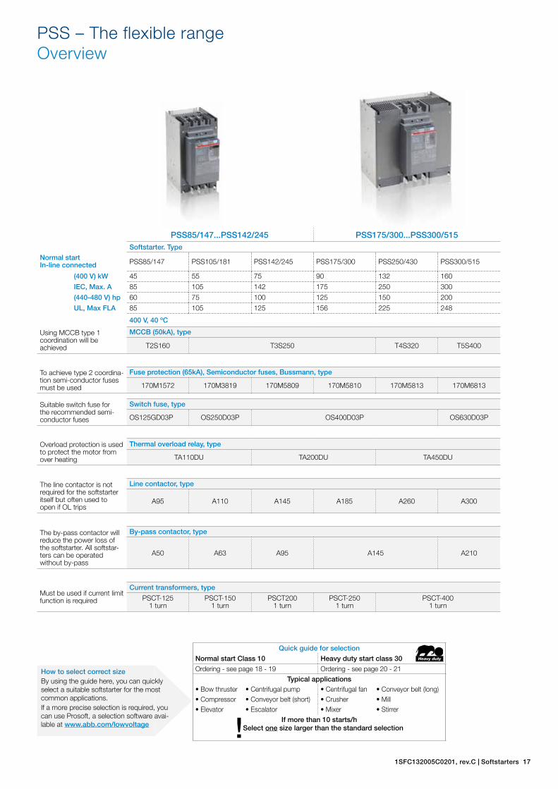
PSS85/147...PSS142/245 PSS175/300...PSS300/515Softstarter. Type
Normal start In-line connected PSS85/147 PSS105/181 PSS142/245 PSS175/300 PSS250/430 PSS300/515
(400 V) kW 45 55 75 90 132 160
IEC, Max. A 85 105 142 175 250 300
(440-480 V) hp 60 75 100 125 150 200
UL, Max FLA 85 105 125 156 225 248
400 V, 40 ºC
Using MCCB type 1 coordination will be achieved
MCCB (50kA), type
T2S160 T3S250 T4S320 T5S400
To achieve type 2 coordina-tion semi-conductor fuses must be used
Fuse protection (65kA), Semiconductor fuses, Bussmann, type
170M1572 170M3819 170M5809 170M5810 170M5813 170M6813
Suitable switch fuse for the recommended semi-conductor fuses
Switch fuse, type
OS125GD03P OS250D03P OS400D03P OS630D03P
Overload protection is used to protect the motor from over heating
Thermal overload relay, type
TA110DU TA200DU TA450DU
The line contactor is not required for the softstarter itself but often used to open if OL trips
Line contactor, type
A95 A110 A145 A185 A260 A300
The by-pass contactor will reduce the power loss of the softstarter. All softstar-ters can be operated without by-pass
By-pass contactor, type
A50 A63 A95 A145 A210
Must be used if current limit function is required
Current transformers, type
PSCT-1251 turn
PSCT-1501 turn
PSCT2001 turn
PSCT-2501 turn
PSCT-4001 turn
PSS – The flexible rangeOverview
Heavy duty
Quick guide for selectionNormal start Class 10 Heavy duty start class 30Ordering - see page 18 - 19 Ordering - see page 20 - 21
Typical applications• Bow thruster • Centrifugal pump • Centrifugal fan • Conveyor belt (long)• Compressor • Conveyor belt (short) • Crusher • Mill• Elevator • Escalator • Mixer • Stirrer
If more than 10 starts/h!Select one size larger than the standard selection
How to select correct sizeBy using the guide here, you can quickly select a suitable softstarter for the most common applications.If a more precise selection is required, you can use Prosoft, a selection software avai-lable at www.abb.com/lowvoltage

1SFC132005C0201, rev.C | Softstarters 23
PSS – The flexible rangeTechnical data
Rated insulation voltage Ui 690 V
Rated operational voltage Ue 208 ... 500 V AC, 400 ... 690 V AC + 10 % / -15 %, 50/60 Hz ±5 %
Rated control supply voltage Us 110 ... 120 V or 220 ... 240 V +10 % / -15 %, 50/60 Hz ±5 %
Rated control circuit voltage Uc Internal 24 V DC
Starting capacity at Ie
at max. rated current, Ie 4 x Ie for 10 sec.
Number of starts per hour 30 1)
Overload capability
Overload class 10Service factor PSS18/30 ... 250/430 PSS300/515
115 % 110 %
Ambient temperature
during operation -25 ºC to + 60 ºC 2)
during storage -40 ºC to + 70 ºC
Maximum altitude 4000 m 3)
Degree of protection PSS18/30-500 ... 44/76-500 PSS50/85-500 ... 72/124-500 PSS85/147-500 ... 300/515-500
Main circuit IP20 IP10 IP00
PSS18/30-690 ... 72/124-690 PSS85/147-690 ... 300/515-690
IP10 IP00
Supply and control circuit PSS18/30 ... PSS300/515
IP20
Signal relays
By-pass signal Yes
Fault signal Yes (NO or NC)
Rated operational voltage, Ue 250 V AC / 24 V DC
Rated thermal current Ie 5A
Rated operational current Ie at AC-15 (Ue=250 V) 1.5 A
Signaling indication LED
Ready to start / ON Green
Completed start ramp / T.O.R Green
General fault Red
External fault Red
Settings
Ramp time during start 1 – 30 sec
Ramp time during stop 0 – 30 sec
Initial voltage during start 30 – 70 %
Current limit function x CT-ratio 1.5 ... 44)
Switch for In-line / Inside Delta Yes
1) Valid for 50 % on time and 50 % off time. 3.5 x Ie for 7 sec., if other data is required, contact your sales office.2) Above 40 ºC up to max. 60 ºC reduce the rated current with 0.8 % per ºC.3) When used at high alitudes above 1000 meters up to 4000 meters you need to derate the rated current using the following formula.[ % of Ie = 100 - x - 1000 ] x = actual altitude for the softstarter 1504) Only if current transformer is connected (accessory).
24 Softstarters | 1SFC132005C0201, rev.C
PSS – The flexible rangeTechnical data
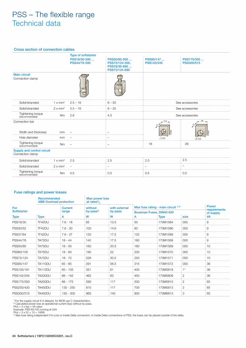
Fuse ratings and power losses
Recommended ABB Overload protection
Max power loss at rated Ie
For Softstarter
Currentrange
without by-pass2)
with external by-pass
Max fuse rating - main circuit 1) 3) Power requirements of supplyBussman Fuses, DIN43 620
Type Type A W W A Type size VA
PSS18/30 TF42DU 7.6 - 18 65 13.5 50 170M1564 000 9
PSS30/52 TF42DU 7.6 - 30 100 14.6 80 170M1566 000 9
PSS37/64 TF42DU 7.6 - 37 120 17.5 125 170M1568 000 9
PSS44/76 TA75DU 18 - 44 142 17.5 160 170M1569 000 9
PSS50/85 TA75DU 18 - 50 160 20.5 160 170M1569 000 10
PSS60/105 TA75DU 18 - 60 190 22 200 170M1570 000 10
PSS72/124 TA75DU 18 - 72 226 30.5 250 170M1571 000 10
PSS85/147 TA110DU 65 - 85 291 56.5 315 170M1572 000 36
PSS105/181 TA110DU 65 - 105 351 61 400 170M3819 1* 36
PSS142/245 TA200DU 66 - 142 462 63 450 170M5809 2 36
PSS175/300 TA200DU 66 - 175 590 117 500 170M5810 2 65
PSS250/430 TA450DU 130 - 250 815 117 700 170M5813 2 65
PSS300/515 TA450DU 130 - 300 965 140 900 170M6813 3 65
1) For the supply circuit 6 A delayed, for MCB use C characteristics.2) Calculated power loss at operational current (Iop) without by-pass.Ptot = 3 x Iop + VA value Example: PSS 60/105 running at 52A Ptot = 3 x 52 + 10 = 166W 3) Max fuse rating independent if In-Line or Inside Delta connection. In Inside Delta connections of PSS, the fuses can be placed outside of the delta.
Cross section of connection cables
Type of softstarterPSS18/30-500 ... PSS44/76-500
PSS50/85-500 ... PSS72/124-500, PSS18/30-690 ... PSS72/124-690
PSS85/147 ... PSS142/245
PSS175/300 ... PSS300/515
Main circuitConnection clamp
Solid/stranded 1 x mm2 2.5 – 16 6 – 50 See accessories
Solid/stranded 2 x mm2 2.5 – 16 6 – 25 See accessories
Tightening torque (recommended) Nm 2.6 4.5 See accessories
Connection bar
Width and thickness mm – –
Hole diameter mm – –
Tightening torque (recommended) Nm – – 18 28
Supply and control circuitConnection clamp
Solid/stranded 1 x mm2 2.5 2.5 2.5 2.5
Solid/stranded 2 x mm2 – – – –
Tightening torque (recommended) Nm 0.5 0.5 0.5 0.5
E18
58D
17.5
ø 8.5
5
E18
59D
20
ø 10.2
5
28 Softstarters | 1SFC132005C0201, rev.C
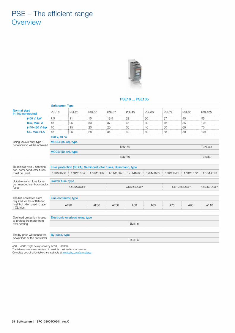
PSE – The efficient rangeOverview
PSE18 ... PSE105
Softstarter. Type
Normal start In-line connected PSE18 PSE25 PSE30 PSE37 PSE45 PSE60 PSE72 PSE85 PSE105
(400 V) kW 7.5 11 15 18.5 22 30 37 45 55
IEC, Max. A 18 25 30 37 45 60 72 85 106
(440-480 V) hp 10 15 20 25 30 40 50 60 75
UL, Max FLA 18 25 28 34 42 60 68 80 104
400 V, 40 ºC
Using MCCB only, type 1 coordination will be achieved
MCCB (35 kA), type
T2N160 T3N250
MCCB (50 kA), type
T2S160 T3S250
To achieve type 2 coordina-tion, semi-conductor fuses must be used
Fuse protection (85 kA), Semiconductor fuses, Bussmann, type
170M1563 170M1564 170M1566 170M1567 170M1568 170M1569 170M1571 170M1572 170M3819
Suitable switch fuse for re-commended semi-conductor fuses
Switch fuse, type
OS32GD03P OS63GD03P OS125GD03P OS250D03P
The line contactor is not required for the softstarter itself but often used to open if OL trips
Line contactor, type
AF26 AF30 AF38 A50 A63 A75 A95 A110
Overload protection is used to protect the motor from over heating
Electronic overload relay, type
Built-in
The by-pass will reduce the power loss of the softstarter.
By-pass, type
Built-in
A50 ... A300 might be replaced by AF50 ... AF300The table above is an overview of possible combinations of devices.Complete coordination tables are available at www.abb.com/lowvoltage

1SFC132005C0201, rev.C | Softstarters 29
PSE – The efficient rangeOverview
PSE142 ... PSE170 PSE210 ... PSE370
Softstarter. Type
Normal start In-line connected PSE142 PSE170 PSE210 PSE250 PSE300 PSE370
(400 V) kW 75 90 110 132 160 200
IEC, Max. A 143 171 210 250 300 370
(440-480 V) hp 100 125 150 200 250 300
UL, Max FLA 130 169 192 248 302 361
400 V, 40 ºC
Using MCCB only, type 1 coordination will be achieved
MCCB (35 kA), type
T3N250 T4N320 T5N400 T5N630
MCCB (50 kA), type
T3S250 T4S320 T5S400 T5S630
To achieve type 2 coordina-tion, semi-conductor fuses must be used
Fuse protection (85kA), Semiconductor fuses, Bussmann, type
170M5809 170M5810 170M5812 170M5813 170M6812 170M6813
Suitable switch fuse for re-commended semi-conductor fuses
Switch fuse, type
OS400D03P OS630D03P
The line contactor is not required for the softstarter itself but often used to open if OL trips
Line contactor, type
A145 A185 A210 A260 A300 AF400
Overload protection is used to protect the motor from over heating
Electronic overload relay, type
Built-in
The by-pass will reduce the power loss of the softstarter.
By-pass, type
Built-in
Quick guide for selectionNormal start Class 10 Heavy duty start class 30Ordering - see page 30 Ordering - see page 31
Typical applications• Bow thruster • Centrifugal pump • Centrifugal fan • Conveyor belt (long)• Compressor • Conveyor belt (short) • Crusher • Mill• Elevator • Escalator • Mixer • Stirrer
If more than 10 starts/h!Select one size larger than the standard selection
How to select correct sizeBy using the guide here, you can quickly select a suitable softstarter for the most common applications.If a more precise selection is required, you can use Prosoft, a selection software avai-lable at www.abb.com/lowvoltage

1SFC132005C0201, rev.C | Softstarters 33
PSE – The efficient rangeTechnical data
Rated insulation voltage Ui 600 V Analog outputRated operational voltage Ue 208 ... 600 V +10 %/-15 % Output signal reference 4 ... 20 mARated control supply voltage Us 100 ... 250 V +10 %/-15 %, 50/60 Hz ±5 % Type of output signal I Amp
Rated control circuit voltage Uc Internal 24 V DC Scaling Fixed at 1.2 x IeStarting capacity at Ie 4xIe for 10 sec. Control circuitNumber of starts per hour 10 1) Number of inputs 3 (start, stop, reset of faults)Overload capability, Signal indication LED’sOverload Class 10 On / Ready Green flashing / steadyAmbient temperature Run / TOR Green flashing / steadyDuring operation -25 … +60 °C 2) Protection YellowDuring storage -40 … +70 °C Fault RedMaximum Altitude 4000 m 3) ProtectionsDegree of protection Electronic overload Yes (Class 10A, 10, 20, 30)Main circuit IP00 Locked rotor protection YesSupply and Control circuit IP20 Underload protection YesMain circuitBuilt-in By-pass Yes Field bus connectionCooling system - Fan cooled Connection for(thermostat controlled) Yes ABB FieldBusPlug Yes (option)HMI for settings External keypadDisplay 4 7-segments and icons. Illuminated Display LCD typeKeypad 2 selection keys and 2 navigation keys Ambient temperatureMain settings during operation -25 … +60 °CSetting current Size dependent during storage -40 … +70 °CRamp time during start 1-30 sec Degree of protection IP66Ramp time during stop 0-30 secInitial / end voltage 30-70%Current limit 1.5-7xIeTorque control for start Yes / NoTorque control for stop Yes / NoKick start Off, 30-100%Signal relaysNumber of signal relays 3K2 Run signalK3 TOR (By-pass) signalK1 Event signalRated operational voltage Ue 250 V AC / 24 V DC 4)
Rated thermal current Ith 3 ARated operational current Ieat AC-15 (Ue = 250 V) 1.5 A1) Valid for 50 % on time and 50 % off time, with 3.5 x Ie for 7 seconds. If other data is required, please contact your sales office2) Above 40 ºC up to max. 60 ºC reduce the rated current with 0.6 % per ºC.3) When used at high alitudes above 1000 meters up to 4000 meters you need to derate the rated current using the following formula.
[ % of Ie = 100 - x - 1000 ] x = actual altitude for the softstarter 1504) A common voltage needs to be used for all 3 signal relays
Class 30Class 20Class 10Class 10A
87654321
10 000
1000
100
10
1
00
Time (s)
Current (x Ie)
Tripping curves for electronic overload protection (Cold)

34 Softstarters | 1SFC132005C0201, rev.C
PSE – The efficient rangeTechnical data
Fuse ratings and power lossesRecommended ABB Overload protection
For Softstarter
Currentrange
Max power loss at rated Ie (Internal by-pass)
Max fuse raiting - main circuit 1)
Power requirements supply circuit
Bussman Fuses, DIN43 620
Type Type A W A Type Size VA/VA pull in
PSEPSE18 Integrated 5.4-18 0.2 40 170M1563 000 16
PSE25 Integrated 7.5-25 0.4 50 170M1564 000 16
PSE30 Integrated 9-30 0.5 80 170M1566 000 16
PSE37 Integrated 11.1-37 0.8 100 170M1567 000 16
PSE45 Integrated 13.5-45 1.2 125 170M1568 000 16
PSE60 Integrated 18-60 2.2 160 170M1569 000 16
PSE72 Integrated 21.6-72 3.1 250 170M1571 000 16
PSE85 Integrated 25.5-85 4.3 315 170M1572 000 16
PSE105 Integrated 31.8-106 6.6 400 170M3819 1* 16
PSE142 Integrated 42.9-143 12.1 450 170M5809 2 16
PSE170 Integrated 51.3-171 17.6 500 170M5810 2 16
PSE210 Integrated 63-210 8.8 630 170M5812 2 23/350
PSE250 Integrated 75-250 12.5 700 170M5813 2 23/350
PSE300 Integrated 90.6-302 18 800 170M6812 3 23/350
PSE370 Integrated 111-370 27.4 900 170M6813 3 23/350
1) For the supply circuit 6 A delayed, for MCB use C characteristics.
Cross section of connection cables
Type of softstarterPSE18 ... PSE105 PSE142 ... PSE170 PSE210 ... PSE370
Main circuitConnection clamp
Solid/stranded 1 x mm2 2.5 – 70 See accessories
Solid/stranded 2 x mm2 2.5 – 70 See accessories
Tightening torque (recommended) Nm 9 See accessories
Connection bar
Width and thickness mm
Hole diameter mm
Tightening torque (recommended) Nm 9 18 28
Supply and control circuitConnection clamp
Solid/stranded 1 x mm2 2.5 2.5 2.5
Solid/stranded 2 x mm2 1.5 1.5 1.5
Tightening torque (recommended) Nm 0.5 0.5 0.5
E18
58D
17.5
ø 8.5
5
E18
59D
20
ø 10.2
5

38 Softstarters | 1SFC132005C0201, rev.C
PST(B) – The advanced range Overview
PST30 ... PST72 PST85 ... PST142
Softstarter. Type
Normal start In-Line connected PST30 PST37 PST44 PST50 PST60 PST72 PST85 PST105 PST142
(400 V) kW 15 18.5 22 25 30 37 45 55 75
IEC, Max. A 30 37 44 50 60 72 85 105 142
(440-480 V) hp 20 25 30 40 40 50 60 75 100
UL, Max FLA 28 34 42 54 60 68 80 104 130
400 V, 40 ºC
Using MCCB only, type 1 coordination will be achieved.
MCCB (50kA), type
T2S160 T3S250
To achieve a type 2 coordina-tion, semi-conductor fuses must be used.
Fuse protection (65kA), Semiconductor fuses, Bussmann, type
170M1566 170M1568 170M1569 170M1570 170M1571 170M1572 170M3819 170M5809
Suitable switch fuse for re-commended semi-conductor fuses.
Switch fuse, type
OS32GD03P OS63GD03P OS125GD03P OS250D03P OS400D03P
The line contactor is not required for the softstarter itself but often used to open if OL trips
Line contactor, type
AF30 AF38 A50 A63 A75 A95 A110 A145
Overload protection is used to protect the motor from over heating
Electronic overload relay
Built-in
The by-pass contactor will reduce the power loss of the softstarter. All softstarters can be operated without by-pass
By-pass contactor, type
AF16 AF26 AF30 A40 A50 A63 A95
A50 ... A300 might be replaced by AF50 ... AF300.The table above is an overview of possible combinations of devices.Complete coordination tables are available at www.abb.com/lowvoltage

1SFC132005C0201, rev.C | Softstarters 39
PST(B) – The advanced range Overview
PST175 ... PST300 PSTB370 ... PSTB470 PSTB570 ... PSTB1050
Softstarter. Type
Normal start In-Line connected PST175 PST210 PST250 PST300 PSTB370 PSTB470 PSTB570 PSTB720 PSTB840 PSTB1050
(400 V) kW 90 110 132 160 200 250 315 400 450 560
IEC, Max. A 175 210 250 300 370 470 570 720 840 1050
(440-480 V) hp 125 150 200 250 300 400 500 600 700 900
UL, Max FLA 156 192 248 302 361 480 590 720 840 1062
400 V, 40 ºC
Using MCCB only, type 1 coordination will be achieved.
MCCB (50kA), type
T4S250 T5S400 T5S630 T6S630 T6S800 T7S1250 T7S1600
To achieve a type 2 coordina-tion, semi-conductor fuses must be used.
Fuse protection (65kA), Semiconductor fuses, Bussmann, type
170M5810 170M5812 170M5813 170M6813 170M5813 170M6813 170M8554 170M6018 170M60202)
Suitable switch fuse for re-commended semi-conductor fuses.
Switch fuse, type
OS400D03P OS630D03P OS400D03P OS630D03P OS800D03P 1)
The line contactor is not required for the softstarter itself but often used to open if OL trips
Line contactor, type
A185 A210 A260 A300 AF400 AF580 AF750 AF1350 AF1650
Overload protection is used to protect the motor from over heating
Electronic overload relay, type
Built-in
The by-pass contactor will reduce the power loss of the softstarter. All softstarters can be operated without by-pass
By-pass contactor, type
A145 A210 Built-in
1) Switch fuse not available. Use Bussman fuse base 170H30042) PSTB1050-690-70 has 170M6019
Quick guide for selectionNormal start Class 10 Heavy duty start class 30Ordering - see page 40 - 41 Ordering - see page 42 - 43
Typical applications• Bow thruster • Centrifugal pump • Centrifugal fan • Conveyor belt (long)• Compressor • Conveyor belt (short) • Crusher • Mill• Elevator • Escalator • Mixer • Stirrer
If more than 10 starts/h!Select one size larger than the standard selection
How to select correct sizeBy using the guide here, you can quickly select a suitable softstarter for the most common applications.If a more precise selection is required, you can use Prosoft, a selection software avai-lable at www.abb.com/lowvoltage
1SFC132005C0201, rev.C | Softstarters 45
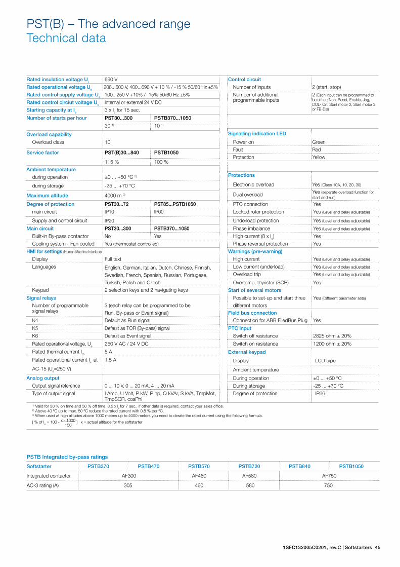
PST(B) – The advanced range Technical data
PSTB Integrated by-pass ratings
Softstarter PSTB370 PSTB470 PSTB570 PSTB720 PSTB840 PSTB1050
Integrated contactor AF300 AF460 AF580 AF750
AC-3 rating (A) 305 460 580 750
Rated insulation voltage Ui 690 V Control circuit
Rated operational voltage Ue 208...600 V, 400...690 V + 10 % / -15 % 50/60 Hz ±5% Number of inputs 2 (start, stop)
Rated control supply voltage Us 100...250 V +10% / -15% 50/60 Hz ±5% Number of additional programmable inputs
2 (Each input can be programmed to be either; Non, Reset, Enable, Jog, DOL- On, Start motor 2, Start motor 3 or FB-Dis)
Rated control circiut voltage Uc Internal or external 24 V DC
Starting capacity at Ie 3 x Ie for 15 sec.
Number of starts per hour PST30...300 PSTB370...1050
30 1) 10 1)
Signalling indication LED Overload capability
Overload class 10 Power on Green
Fault RedService factor PST(B)30...840 PSTB1050Protection Yellow
115 % 100 %
Ambient temperatureProtectionsduring operation ±0 ... +50 °C 2)
during storage -25 ... +70 °C Electronic overload Yes (Class 10A, 10, 20, 30)
Dual overload Yes (separate overload function for start and run)Maximum altitude 4000 m 3)
Degree of protection PST30...72 PST85...PSTB1050 PTC connection Yes
main circuit IP10 IP00 Locked rotor protection Yes (Level and delay adjustable)
Supply and control circuit IP20 Underload protection Yes (Level and delay adjustable)
Main circuit PST30...300 PSTB370...1050 Phase imbalance Yes (Level and delay adjustable)
Built-in By-pass contactor No Yes High current (8 x Ie) Yes
Cooling system - Fan cooled Yes (thermostat controlled) Phase reversal protection Yes
HMI for settings (Human Machine Interface) Warnings (pre-warning)
Display Full text High current Yes (Level and delay adjustable)
Languages English, German, Italian, Dutch, Chinese, Finnish, Low current (underload) Yes (Level and delay adjustable)
Swedish, French, Spanish, Russian, Portugese, Overload trip Yes (Level and delay adjustable)
Turkish, Polish and Czech Overtemp, thyristor (SCR) YesKeypad 2 selection keys and 2 navigating keys Start of several motors
Signal relays Possible to set-up and start three Yes (Different parameter sets)
Number of programmable 3 (each relay can be programmed to be different motorssignal relays Run, By-pass or Event signal) Field bus connection
K4 Default as Run signal Connection for ABB FiledBus Plug Yes
K5 Default as TOR (By-pass) signal PTC input
K6 Default as Event signal Switch off resistance 2825 ohm ± 20%
Rated operational voltage, Ue 250 V AC / 24 V DC Switch on resistance 1200 ohm ± 20%
Rated thermal current Ith 5 A External keypad
Rated operational current Ie at 1.5 A Display LCD type
AC-15 (Ue=250 V) Ambient temperature
Analog output During operation ±0 ... +50 °C
Output signal reference 0 ... 10 V, 0 ... 20 mA, 4 ... 20 mA During storage -25 ... +70 °C
Type of output signal I Amp, U Volt, P kW, P hp, Q kVAr, S kVA, TmpMot, TmpSCR, cosPhi
Degree of protection IP66
1) Valid for 50 % on time and 50 % off time. 3.5 x Ie for 7 sec., if other data is required, contact your sales office.2) Above 40 ºC up to max. 50 ºC reduce the rated current with 0.8 % per ºC.3) When used at high alitudes above 1000 meters up to 4000 meters you need to derate the rated current using the following formula.
[ % of Ie = 100 - x - 1000 ] x = actual altitude for the softstarter 150

46 Softstarters | 1SFC132005C0201, rev.C
PST(B) – The advanced range Technical data
Major possible settings and the displayed text and the set default values
Description Text on display Eng)
Values on display Default value
Setting current for overload, locked rotor etc. Setting Ie 9.0 ...1207 A divided into 19 overlapping ranges. See table, page 48Time for start ramp Start Ramp 1 ... 30 s, 1 ... 120 s (Range depends on Start Range) 10 sTime for stop ramp Stop Ramp 0 ... 30 s, 0 ... 120 s (Range depends on Stop Range) 0 sInitial voltage for start ramp Init Volt 30 ... 70 % 30 %End voltage for stop ramp End Volt 30 ... 70 % 30 %Step down voltage Step Down 30 ...100 % 100 %Level of the current limit. Current Lim 1.5 ... 7.0 x Ie 4.0 x IeSelection of Kick start Kick Start Yes, No NoLevel of Kick start if selected Kick Level 50 ... 100 % 50 %Time for Kick start if selected Kick Time 0.1 ... 1.5 s 0.2Selectable range for start ramp Start Range 1 ... 30 s, 1...120 s 1 ... 30 sSelectable range for stop ramp Stop Range 0 ... 30 s, 0 ... 120 s 0 ... 30 sOverload protection Overload No, Normal, Dual NormalOverload Class OL Class 10 A, 10, 20, 30 10Overload Class, Dual type, Start Class OL Class S 10A, 10, 20, 30 10Overload Class, Dual type, Run Class OL Class R 10A, 10, 20, 30 10Type of operation for overload protection OL Op Stop-M, Stop-A, Ind Stop-MLocked rotor protection Locked Rotor Yes, No NoTrip level for locked rotor protection Lock R Lev 0.5 ... 8.0 x Ie 4.0 x IeTrip time for locked rotor protection Lock R Time 0.2 ... 10 s 1.0 sType of operation for locked rotor protection Lock R Op Stop-M, Stop-A, Ind Stop-MUnderload protection Underload Yes, No NoTrip level for Underload protection Underl Lev 0.4 ... 0.8 x Ie 0.5 x IeTrip time for Underload protection Underl Time 1 ... 30 s 10 sType of operation for Underload protection Underl Op Stop-M, Stop-A, Ind Stop-MPhase imbalance protection Phase Imb Yes, No NoTrip level for phase imbalance protection Ph Imb Lev 10 ... 80 % 80 %Type of operation for phase imbalance protection Ph Imb Op Stop-M, Stop-A, Ind Stop-MHigh current protection High I Yes, No NoType of operation for high current protection High I Op Stop-M, Stop-A, Ind Stop-MPhase reversal protection Phase Rev Yes, No NoType of operation for phase reversal protection Ph Rev Op Stop-M, Stop-A, Ind Stop-MPTC protection PTC Yes, No NoType of operation for PTC protection PTC Op Stop-M, Stop-A Stop-MAn external Bypass contactor is used Ext ByPass Yes, No NoHigh current warning Warn I=High Yes, No NoTrip level for high current warning Wa I=H Lev 0.5 ... 5.0 x Ie 1.2 x IeLow current warning Warn I=Low Yes, No NoTrip level for low current warning Wa I=L Lev 0.4 ...1.0 x Ie 0.8 x IeOverload warning Warn OL Yes, No NoTrip level for overload warning Wa OL Lev 40 ... 99 % 90 %Thyristor overload warning Warn SCR OL Yes, No NoType of operation for phase loss fault Ph Loss Op Stop-M, Stop-A Stop-MType of operation for by-pass doesn’t close BP open Op Stop-M, Stop-A Stop-MType of operation for by-pass doesn’t open BP closed Op Stop-M, Stop-A Stop-MType of operation for fieldbus fault FB Fault Op Stop-M, Stop-A Stop-MType of operation for frequency fault Freq F Op Stop-M, Stop-A Stop-MType of operation for heat sink over temperature fault HS Temp Op Stop-M, Stop-A Stop-MType of operation for thyristor short circuit fault SCR SC Op Stop-M, Stop-A Stop-MFunction of programmable input In_0 In0 None, Reset, Enable, Jog, DOL, Start 2, FB-Dis ResetFunction of programmable input In_1 In1 None, Reset, Enable, Jog, DOL, Start 3, FB-Dis ResetFunction of programmable relay output K4 Relay K4 Run, TOR, Event RunFunction of programmable relay output K5 Relay K5 Run, TOR, Event TORFunction of programmable relay output K6 Relay K6 Run, TOR, Event EventControl of the softstarter with fieldbus Fieldb Ctrl Yes, No NoNumber of sequences for sequence start. No of Seq No, 2, 3 NoLanguage to use on display Language US/UK, FI, SE, PT, NL, IT, FR, ES, DE, CN, RU, TR, PL, CZ US/UKPassword for display Password No, 1 ... 255Start mode Start Mode Volt, Torque VoltStop mode Stop Mode Volt, Torque VoltTorque limit Torque limit 20 ... 200 % 150 %Analog output Analogue Out Yes, No NoAnalog output, reference Anl Ref 0 ...10 V, 0 ... 20 mA, 4 ... 20 mA 4 ...20 mAAnalog output, type of value Anl Type I Amp, U Volt, P kW, P hp, Q kVAr, S kVA, TmpMot, TmpSCR, cosPhi I Amp

1SFC132005C0201, rev.C | Softstarters 47
PST(B) – The advanced range Technical data
Tripping curves for the integrated electronic overload protection
All units have an integrated electronic overload protection possible to set on four different tripping classes.Below you find a curve for each tripping class in cold state. These tripping curves are valid for PSE, PST and PSTB
Class 30Class 20Class 10Class 10A
87654321
10 000
1000
100
10
1
00
Time (s)
Current (x Ie)
1SFC
1321
34F0
201
Tripping curves for electronic overload protection (Cold) for PSE, PST and PSTB.
48 Softstarters | 1SFC132005C0201, rev.C
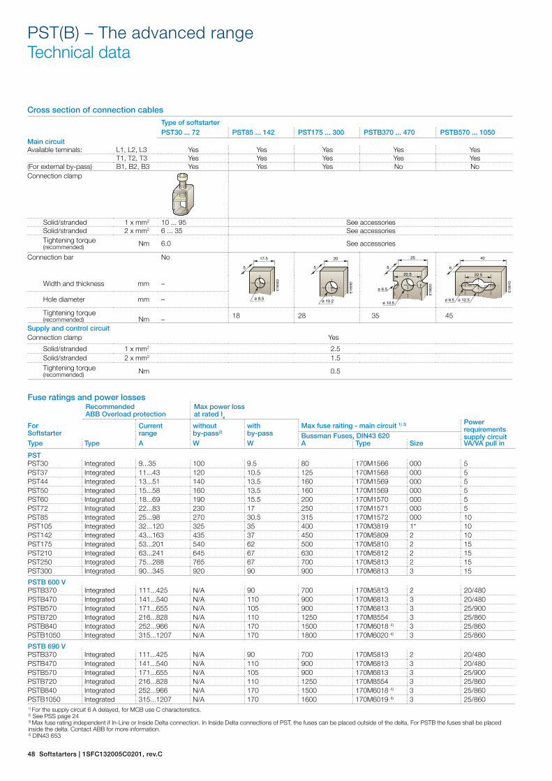
Cross section of connection cables Type of softstarterPST30 ... 72 PST85 ... 142 PST175 ... 300 PSTB370 ... 470 PSTB570 ... 1050
Main circuitAvailable teminals: L1, L2, L3 Yes Yes Yes Yes Yes
T1, T2, T3 Yes Yes Yes Yes Yes(For external by-pass) B1, B2, B3 Yes Yes Yes No NoConnection clamp
Solid/stranded 1 x mm2 10 ... 95 See accessoriesSolid/stranded 2 x mm2 6 ... 35 See accessoriesTightening torque (recommended) Nm 6.0 See accessories
Connection bar No
Width and thickness mm –
Hole diameter mm –
Tightening torque (recommended) Nm – 18 28 35 45
Supply and control circuitConnection clamp Yes
Solid/stranded 1 x mm2 2.5Solid/stranded 2 x mm2 1.5Tightening torque (recommended) Nm 0.5
PST(B) – The advanced range Technical data
Fuse ratings and power lossesRecommended ABB Overload protection
Max power loss at rated Ie
For Softstarter
Currentrange
without by-pass2)
withby-pass
Max fuse raiting - main circuit 1) 3) Power requirements supply circuitBussman Fuses, DIN43 620
Type Type A W W A Type Size VA/VA pull in
PSTPST30 Integrated 9...35 100 9.5 80 170M1566 000 5PST37 Integrated 11...43 120 10.5 125 170M1568 000 5PST44 Integrated 13...51 140 13.5 160 170M1569 000 5PST50 Integrated 15...58 160 13.5 160 170M1569 000 5PST60 Integrated 18...69 190 15.5 200 170M1570 000 5PST72 Integrated 22...83 230 17 250 170M1571 000 5PST85 Integrated 25...98 270 30.5 315 170M1572 000 10PST105 Integrated 32...120 325 35 400 170M3819 1* 10PST142 Integrated 43...163 435 37 450 170M5809 2 10PST175 Integrated 53...201 540 62 500 170M5810 2 15PST210 Integrated 63...241 645 67 630 170M5812 2 15PST250 Integrated 75...288 765 67 700 170M5813 2 15PST300 Integrated 90...345 920 90 900 170M6813 3 15
PSTB 600 VPSTB370 Integrated 111...425 N/A 90 700 170M5813 2 20/480PSTB470 Integrated 141...540 N/A 110 900 170M6813 3 20/480PSTB570 Integrated 171...655 N/A 105 900 170M6813 3 25/900PSTB720 Integrated 216...828 N/A 110 1250 170M8554 3 25/860PSTB840 Integrated 252...966 N/A 170 1500 170M6018 4) 3 25/860PSTB1050 Integrated 315...1207 N/A 170 1800 170M6020 4) 3 25/860
PSTB 690 VPSTB370 Integrated 111...425 N/A 90 700 170M5813 2 20/480PSTB470 Integrated 141...540 N/A 110 900 170M6813 3 20/480PSTB570 Integrated 171...655 N/A 105 900 170M6813 3 25/900PSTB720 Integrated 216...828 N/A 110 1250 170M8554 3 25/860PSTB840 Integrated 252...966 N/A 170 1500 170M6018 4) 3 25/860PSTB1050 Integrated 315...1207 N/A 170 1600 170M6019 4) 3 25/8601) For the supply circuit 6 A delayed, for MCB use C characteristics.2) See PSS page 243) Max fuse rating independent if In-Line or Inside Delta connection. In Inside Delta connections of PST, the fuses can be placed outside of the delta. For PSTB the fuses shall be placed inside the delta. Contact ABB for more information. 4) DIN43 653
E18
58D
17.5
ø 8.5
5
E18
59D
20
ø 10.2
5
E18
60D
25
ø 6.5
22.5
ø 10.5
6
E18
61D
40
ø 6.5
22.5
ø 12.5
6