pst-4 - virginia department of · pdf filetype b interior slab mark no. ... file no. pst-4-3...
TRANSCRIPT
S&B DIV
S&B DIV
S&B DIV
PS
T-4
PST-4
TRANSVERSE TENDONS
TYPE B
INTERIOR SLAB
Mark No.
REINFORCING STEEL SCHEDULE
SizeSlab Size Length Location/Pin o
SS0501 SH0401 SV0501 SV0402
Number of bars shown in table are per slab per slab type.
Dimensions in bending diagram are out-to-out of bars.
Type B
Interior slab
4'-0" x 21"
#5 Top longitudinalSL0501
SS0501 #5 Stirrup
SV0501 #5 End vertical
SH0401 End horizontal#4
2•"
SV0402 #4 3" Composite vertical
Scale: ƒ" = 1'-0" unless otherwise noted
/
/
12"
X'-
X"
1'-
6"
1'-
4•
"
4•
"
1'-3‚"
2'-8ƒ"
3'-6•"
3"
3ƒ"
5'-4"
6'-9"
3'-8"
05-03-2018
= 1'-
6"
@ 6"
3 spa.
= 1'-
6"
@ 6"
3 spa.
4"
4"
4"
SV0501
4'-
0"
X - SH0401
3"@ 3"
6 spa.
= 1'-6" = 1'-6"
@ 4•"
4 spa.
X"
X"
C
XX'-XX" XX'-XX" XX'-XX"
XX'-XX"
XX'-XX"
min. lapSL0501
2 - SS0501
2'-6"
Typ. each end
transverse tendon centerline
5" typ. each side of each
PLAN
L 3" o precast hole for transverse tendonC/
centerline unless otherwise shown
Reinforcement symmetrical about slab
2 - SS0501 - XX spa. @ X" = XX'-XX"
2 - SV0402 - XX spa. @ X" = XX'-XX"
1'-9"
L slab
min. la
p
1'-
9"
L voidsC
/CL 1" o void drain
4'-0"
21 spa. @ 2" = 3'-6"
12"
9"
10•
"
1'-
9"
L voidsC
4'-0"
= 4"
2 spa.
@ 2"
2‚
"
Scale: 1" = 1'-0"
STRAND PATTERNScale: 1" = 1'-0"
REINFORCING DETAILS
1'-
2‚
"
1'-
4‚
"
1'-
6‚
"
/CL 1" o void drain
SS0501
/C
hole for trans-
verse tendon
L 3" o precast/C
hole for trans-
verse tendon
L 3" o precast
strand location
Permissible courtesy
Row 1
Row 6
X"
SL0501each side
SV0402 typ.
3" typ.
1'-9" min. lap
ELEVATION
L 3" o precast hole for transverse tendonC/
Reinforcement symmetrical about slab centerline unless otherwise shown
1'-
9"
3‚
"S
H0401
X - SV0501
= 12"
@ 6"
2 spa.
2‚
"
Central Office.
is on file in the
standard drawing
sealed and signed
A copy of the original
May 3, 2018
On the date of
Lic. No. 033572
Junyi Meng
Sealed and Signed by:
CAMBER DIAGRAM
L storage supportsC
MidspanDesign camber, N
erection is exceeded unless otherwised approved by the Engineer.
camber management plan when 75 percent of the design camber at
erection shall not exceed +30%. The Contractor shall implement a
differential from the design camber at erection at the time of
camber at erection is computed using PCI multipliers. Camber
indicated in the Specifications and as modified herein. Design
in the design and detailing of these plans with the tolerances
Design cambers at release and erection are the cambers used
full bearing of the slab on all the pads.
make such adjustment as directed by the Engineer to ensure the
elevations may be needed. It is the Contractor's responsibility to
Due to construction tolerances, adjustment to the bridge seat
shape as shown on the plans by an approved epoxy mortar.
Slab corners damaged during construction shall be restored to their
each to 8,000 lbs at the locations indicated.
The Contractor has the option of stressing two courtesy strands
to the Engineer for approval.
The Contractor may submit an alternate prestressing strand pattern
stirrup may be made from one single bar.
In lieu of splicing two reinforcing bars to form each stirrup, the
clear 3" o hole for transverse tendon.
SS series may be slighty shifted as directed by the Engineer to
Class __.
All reinforcing bars shall be Corrosion Resistant Reinforcing Steel,
Notes:
Date Plan No. Sheet No.Designed: ...........
Drawn: ................
Checked: ............2018, Commonwealth of Virginiac
No. Description Date
STRUCTURE AND BRIDGE DIVISION
COMMONWEALTH OF VIRGINIA
DEPARTMENT OF TRANSPORTATION
Revisions
ROUTE
FEDERAL AID
PROJECT ROUTE PROJECT
STATE SHEET
NO.
VA.
STATEROUTE
FEDERAL AID
PROJECT ROUTE PROJECT
STATE SHEET
NO.
VA.
STATE
STRUCTURAL ENGINEER
RICHMOND, VA
VDOT S&B DIVISION
PS
T_4.d
gn
No. of strands per row
PRESTRESSING STEEL DATA TABLE
1
Row
2
Row
3
Row
4
Row
5
Row
6
RowType
Strand
Strands
Relaxation
0.6" o Low
in.
1
Row
in.
2
Row
in.
3
Row
in.
4
Row
in.
5
Row
in.
6
Row
/
lbs.
strand
force per
stressing
Pre-
in.
Release
At
in.
Erection
At
Design Camber, N
Slab Size
Distance from bottom of slab
per slab
strands
of
number
Total
4'-0" x 21" Type B

STANDARD PST-4: NOTES TO DESIGNER PART 5 DATE: 20Apr2017 SHEET 2 of 4
FILE NO. PST-4-2
PRESTRESSED CONCRETE ADJACENT MEMBER STANDARD
VOIDED SLABS – TRANSVERSE TENDONS INTERIOR SLAB – TYPE B
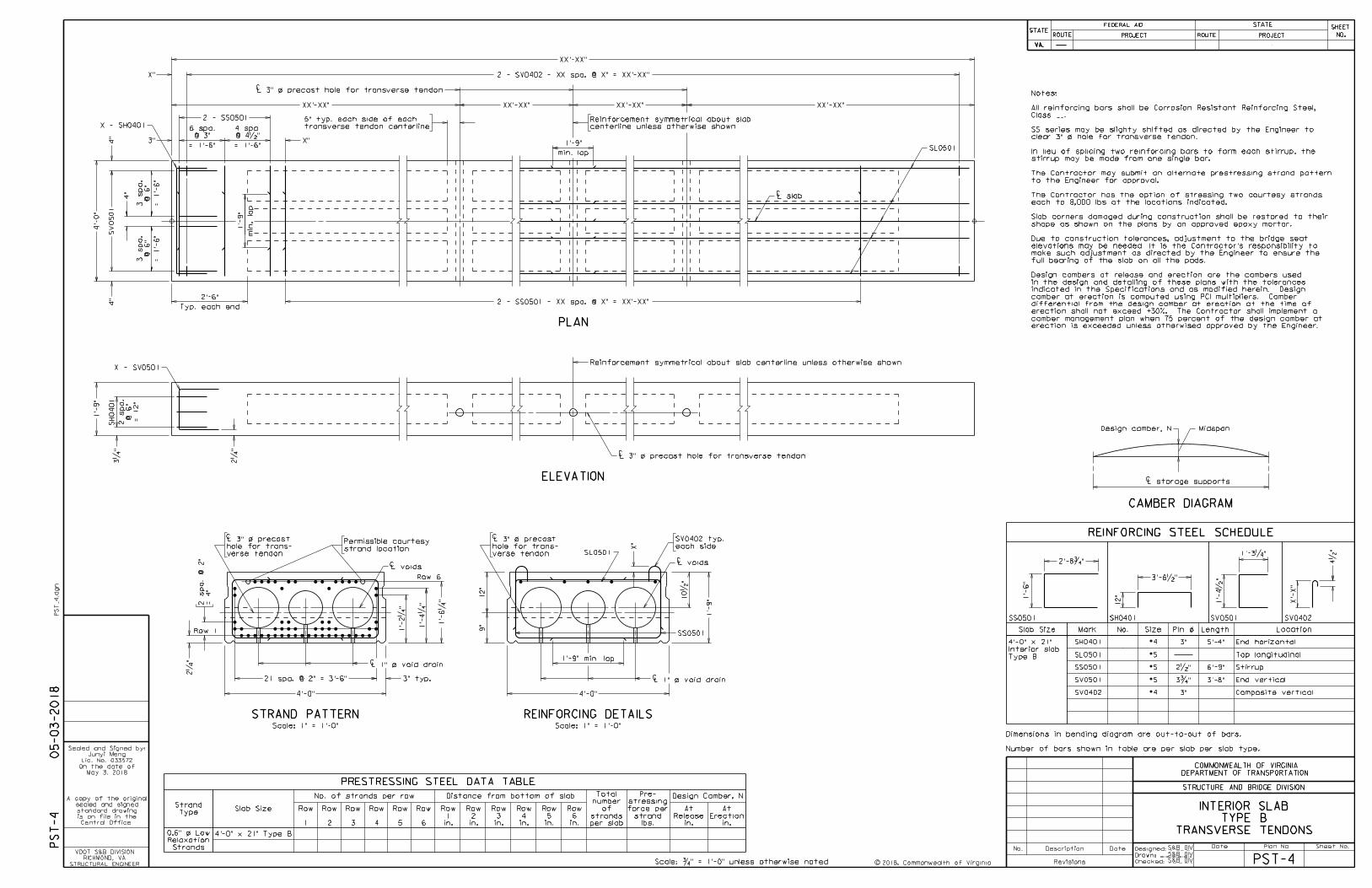
NOTES TO DESIGNER: Include standard PST-1, PST-2A or -2B, PST-3 and PST-6A or -6B in the plans when using this standard. Include standard PST-5A in the plans when using F-shape parapet. Cells for PLAN, ELEVATION, STRAND PATTERN AND REINFORCING DETAILS are provided for an interior 4’-0” x 21” voided slab. Replace with appropriate cells where other width or depth is used. Cells for completing the standard are located in the PSC_VS.CEL library. All bar sizes, reinforcement spacing and strand positions provided in cells are input field holders and are to be adjusted as per design.
ADD THE FOLLOWING NOTES, DIMENSIONS, DETAILS, ETC. TO STANDARD: PLAN: Place appropriate PLAN from cell library. Adjust bar sizes and spacing per design. Enter transverse tendon spacing. Cells detail tendons at quarter points for slabs constrained from lateral movement by wing haunches cast tight against the slabs. Remove tendon position at midspan for third points or both outside tendon positions for half point only. Add end tendon positions where slabs are not constrained from lateral movement. See Part 2, Section 12.05, of this manual for tendon requirements. Where tendon positions are removed, show continuous void outlines. Adjust end stirrup spacing as necessary and enter stirrup spacing throughout span. Enter composite bar spacing or remove bars/dimensioning where composite bars are not used. Remove SL series lap where not required. For skews greater than 10 degrees, cells are not available and the PLAN shall be developed by the Designer to the actual skew. ELEVATION: Place appropriate ELEVATION from cell library. Adjust bar sizes and spacing per design. Adjust tendon positions to match PLAN view. STRAND PATTERN: Remove strands from positions not used per design. Adjust or add strand spacing dimensioning as needed per design. Courtesy strand positions must be on 2” x 2” grid established by position of bottom strands.
STANDARD PST-4: NOTES TO DESIGNER PART 5 DATE: 03May2018 SHEET 3 of 4
FILE NO. PST-4-3
PRESTRESSED CONCRETE ADJACENT MEMBER STANDARD
VOIDED SLABS – TRANSVERSE TENDONS INTERIOR SLAB – TYPE B
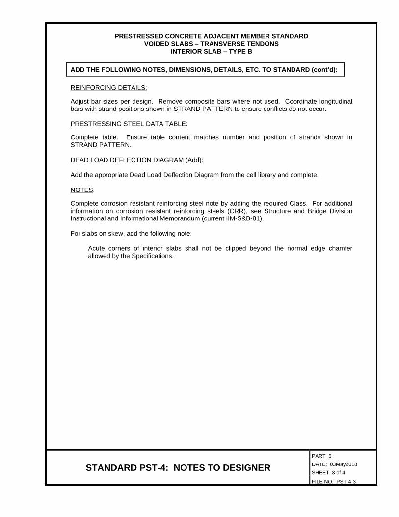
ADD THE FOLLOWING NOTES, DIMENSIONS, DETAILS, ETC. TO STANDARD (cont’d): REINFORCING DETAILS: Adjust bar sizes per design. Remove composite bars where not used. Coordinate longitudinal bars with strand positions shown in STRAND PATTERN to ensure conflicts do not occur. PRESTRESSING STEEL DATA TABLE: Complete table. Ensure table content matches number and position of strands shown in STRAND PATTERN. DEAD LOAD DEFLECTION DIAGRAM (Add): Add the appropriate Dead Load Deflection Diagram from the cell library and complete. NOTES: Complete corrosion resistant reinforcing steel note by adding the required Class. For additional information on corrosion resistant reinforcing steels (CRR), see Structure and Bridge Division Instructional and Informational Memorandum (current IIM-S&B-81). For slabs on skew, add the following note:
Acute corners of interior slabs shall not be clipped beyond the normal edge chamfer allowed by the Specifications.
STANDARD PST-4: NOTES TO DESIGNER PART 5 DATE: 20Apr2017 SHEET 4 of 4
FILE NO. PST-4-4
PRESTRESSED CONCRETE ADJACENT MEMBER STANDARD
VOIDED SLABS – TRANSVERSE TENDONS INTERIOR SLAB – TYPE B
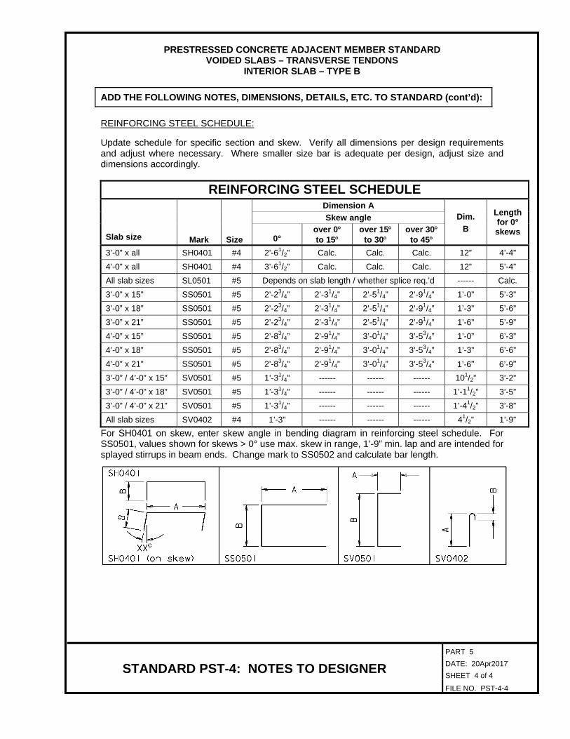
ADD THE FOLLOWING NOTES, DIMENSIONS, DETAILS, ETC. TO STANDARD (cont’d): REINFORCING STEEL SCHEDULE: Update schedule for specific section and skew. Verify all dimensions per design requirements and adjust where necessary. Where smaller size bar is adequate per design, adjust size and dimensions accordingly.
REINFORCING STEEL SCHEDULE
Slab size Mark Size
Dimension A Length for 0° skews
Skew angle Dim.
0° over 0 to 15
over 15 to 30
over 30 to 45
B
3’-0” x all SH0401 #4 2’-61/2” Calc. Calc. Calc. 12” 4’-4” 4’-0” x all SH0401 #4 3’-61/2” Calc. Calc. Calc. 12” 5’-4” All slab sizes SL0501 #5 Depends on slab length / whether splice req.’d ------ Calc. 3’-0” x 15” SS0501 #5 2’-23/4” 2’-31/4” 2’-51/4” 2’-91/4” 1’-0” 5’-3” 3’-0” x 18” SS0501 #5 2’-23/4” 2’-31/4” 2’-51/4” 2’-91/4” 1’-3” 5’-6” 3’-0” x 21” SS0501 #5 2’-23/4” 2’-31/4” 2’-51/4” 2’-91/4” 1’-6” 5’-9” 4’-0” x 15” SS0501 #5 2’-83/4” 2’-91/4” 3’-01/4” 3’-53/4” 1’-0” 6’-3” 4’-0” x 18” SS0501 #5 2’-83/4” 2’-91/4” 3’-01/4” 3’-53/4” 1’-3” 6’-6” 4’-0” x 21” SS0501 #5 2’-83/4” 2’-91/4” 3’-01/4” 3’-53/4” 1’-6” 6’-9” 3’-0” / 4’-0” x 15” SV0501 #5 1’-31/4” ------ ------ ------ 101/2” 3’-2” 3’-0” / 4’-0” x 18” SV0501 #5 1’-31/4” ------ ------ ------ 1’-11/2” 3’-5” 3’-0” / 4’-0” x 21” SV0501 #5 1’-31/4” ------ ------ ------ 1’-41/2” 3’-8” All slab sizes SV0402 #4 1’-3” ------ ------ ------ 41/2” 1’-9”
For SH0401 on skew, enter skew angle in bending diagram in reinforcing steel schedule. For SS0501, values shown for skews > 0° use max. skew in range, 1’-9” min. lap and are intended for splayed stirrups in beam ends. Change mark to SS0502 and calculate bar length.