ptc thermistors as limit temperature sensors - farnell … · ptc thermistors as limit temperature...
TRANSCRIPT
PTC thermistors as
limit temperature sensors
SMD, EIA case sizes 0402, 0603 and 0805,
superior series
Series/Type: B59421, B59641, B59721
Date: January 2011
© EPCOS AG 2011. Reproduction, publication and dissemination of this publication, enclosures hereto and theinformation contained therein without EPCOS' prior express consent is prohibited.
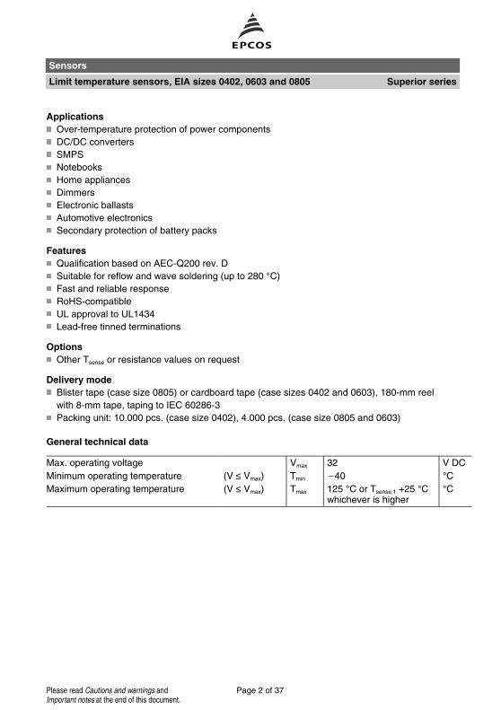
Applications
Over-temperature protection of power components
DC/DC converters
SMPS
Notebooks
Home appliances
Dimmers
Electronic ballasts
Automotive electronics
Secondary protection of battery packs
Features
Qualification based on AEC-Q200 rev. D
Suitable for reflow and wave soldering (up to 280 °C)
Fast and reliable response
RoHS-compatible
UL approval to UL1434
Lead-free tinned terminations
Options
Other Tsense or resistance values on request
Delivery mode
Blister tape (case size 0805) or cardboard tape (case sizes 0402 and 0603), 180-mm reel
with 8-mm tape, taping to IEC 60286-3
Packing unit: 10.000 pcs. (case size 0402), 4.000 pcs. (case size 0805 and 0603)
General technical data
Max. operating voltage Vmax 32 V DC
Minimum operating temperature (V ≤ Vmax) Tmin 40 °CMaximum operating temperature (V ≤ Vmax) Tmax 125 °C or Tsense,1 +25 °C
whichever is higher°C
Sensors
Limit temperature sensors, EIA sizes 0402, 0603 and 0805 Superior series
Page 2 of 37Please read Cautions and warnings andImportant notes at the end of this document.

Electrical specifications and ordering codes
RR
(V ≤ Vmax)
Ω
∆RR
%
Tsense,1
(@ 4.7 kΩ)
°C
Tsense,2
(@ 47 kΩ)
°C
Ordering code
EIA case size 0402
470 ±50 75 ±5 - B59421A0075A062
470 ±50 85 ±5 - B59421A0085A062
470 ±50 95 ±5 - B59421A0095A062
470 ±50 105 ±5 - B59421A0105A062
470 ±50 115 ±5 - B59421A0115A062
470 ±50 125 ±5 - B59421A0125A062
470 ±50 135 ±5 - B59421A0135A062
EIA case size 0603
470 ±50 75 ±5 90 ±7 B59641A0075A062
470 ±50 85 ±5 100 ±7 B59641A0085A062
470 ±50 95 ±5 110 ±7 B59641A0095A062
470 ±50 105 ±5 120 ±7 B59641A0105A062
470 ±50 115 ±5 130 ±7 B59641A0115A062
470 ±50 125 ±5 140 ±7 B59641A0125A062
470 ±50 135 ±5 150 ±7 B59641A0135A062
470 ±50 145 ±5 - B59641A0145A062
Note:
In order to limit self heating effects the electrical power during measurement should be below
2 mW for case size 0402 and below 4 mW for case size 0603.
Sensors
Limit temperature sensors, EIA sizes 0402, 0603 and 0805 Superior series
Page 3 of 37Please read Cautions and warnings andImportant notes at the end of this document.
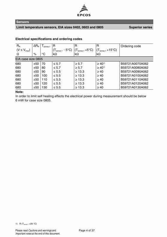
1) R (Tsense,1 +25 °C)
Electrical specifications and ordering codes
RR
(V ≤ Vmax)
Ω
∆RR
%
Tsense,1
°C
R
(Tsense,1 5°C)
kΩ
R
(Tsense,1 +5°C)
kΩ
R
(Tsense,1 +15°C)
kΩ
Ordering code
EIA case size 0805
680 ±50 70 ≤ 5.7 ≥ 5.7 ≥ 401) B59721A0070A062
680 ±50 80 ≤ 5.7 ≥ 5.7 ≥ 401) B59721A0080A062
680 ±50 90 ≤ 5.5 ≥ 13.3 ≥ 40 B59721A0090A062
680 ±50 100 ≤ 5.5 ≥ 13.3 ≥ 40 B59721A0100A062
680 ±50 110 ≤ 5.5 ≥ 13.3 ≥ 40 B59721A0110A062
680 ±50 120 ≤ 5.5 ≥ 13.3 ≥ 40 B59721A0120A062
680 ±50 130 ≤ 5.5 ≥ 13.3 ≥ 40 B59721A0130A062
Note:
In order to limit self heating effects the electrical power during measurement should be below
6 mW for case size 0805.
Sensors
Limit temperature sensors, EIA sizes 0402, 0603 and 0805 Superior series
Page 4 of 37Please read Cautions and warnings andImportant notes at the end of this document.

Dimensional drawings in mm
EIA case size 0402 Solder pad
Recommended maximum dimensions (mm)
EIA case size 0603 Solder pad
Recommended maximum dimensions (mm)
EIA case size 0805 Solder pad
Recommended maximum dimensions (mm)
Sensors
Limit temperature sensors, EIA sizes 0402, 0603 and 0805 Superior series
Page 5 of 37Please read Cautions and warnings andImportant notes at the end of this document.

Reliability data
Test Standard Test conditions ∆R25/R25
Electrical endurance,
cycling
IEC 60738-1 Room temperature: Ismax , Vmax;
Number of cycles: 100
< 10%
Electrical endurance,
constant
IEC 60738-1 Storage at Vmax/Top
T = 85 °CTest duration: 1000 h
< 20%
Damp heat IEC 60738-1 Temperature of air: 40 °CRelative humidity of air: 93%
Duration: 56 days
Test according to IEC 60068-2-78
< 10%
Rapid change
of temperature
IEC 60738-1 TLCT = 25 °C, TUCT = 125 °CNumber of cycles: 5
Test duration: 30 min
Test according to IEC 60068-2-14, test Na
< 10%
Vibration I IEC 60738-1 Frequency: 10 - 55 - 10 Hz
Displacement amplitude: 0.75 mm, resp.
Acceleration: 50 m/s2
Test duration: 3 × 2 h
Test according to IEC 60028-2-6, test Fc
< 5%
Vibration II MIL-STD-202,
method 204
Frequency: 10 ... 2000 Hz
Displacement amplitude: 0.75 mm, resp.
Acceleration: 50 m/s2
Test duration: 3 × 2 h
Test according to IEC 60028-2-6, test Fc
< 5%
Bump IEC 60738-1 Pulse shape: half-sine
Acceleration: 400 m/s2
Pulse duration: 6 ms; 6 x 4000 pulses
Test according to IEC 60068-2-27, test Ea
< 5%
Climatic sequence IEC 60738-1 Dry heat: TUCT = 125 °CTest duration: 16 h
Damp heat first cycle
Cold: TLCT = 25 °CTest duration: 2 h
Damp heat 5 cycles
Tests performed according to
IEC 60068-2-30
< 10%
Bending test EN 130000/4.35 Components reflow-soldered to test board
Maximum bendig: 2 mm
< 5%
Adhesive strength on
PCB
Shearing of the component soldered on PCB
by a force of 5 N is normal to components
longitudinal axis
No
visible
damage
Sensors
Limit temperature sensors, EIA sizes 0402, 0603 and 0805 Superior series
Page 6 of 37Please read Cautions and warnings andImportant notes at the end of this document.
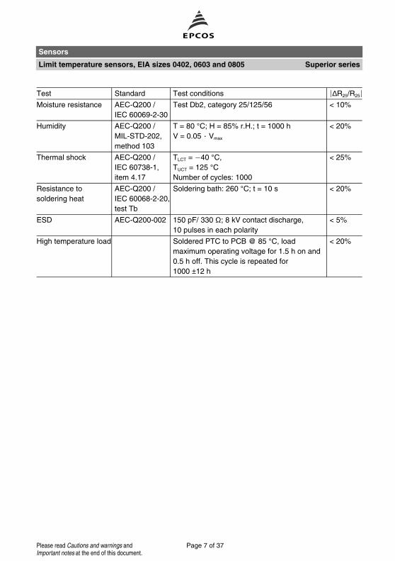
Test Standard Test conditions ∆R25/R25
Moisture resistance AEC-Q200 /
IEC 60069-2-30
Test Db2, category 25/125/56 < 10%
Humidity AEC-Q200 /
MIL-STD-202,
method 103
T = 80 °C; H = 85% r.H.; t = 1000 h
V = 0.05 Vmax
< 20%
Thermal shock AEC-Q200 /
IEC 60738-1,
item 4.17
TLCT = 40 °C,
TUCT = 125 °CNumber of cycles: 1000
< 25%
Resistance to
soldering heat
AEC-Q200 /
IEC 60068-2-20,
test Tb
Soldering bath: 260 °C; t = 10 s < 20%
ESD AEC-Q200-002 150 pF/ 330 Ω; 8 kV contact discharge,
10 pulses in each polarity
< 5%
High temperature load Soldered PTC to PCB @ 85 °C, load
maximum operating voltage for 1.5 h on and
0.5 h off. This cycle is repeated for
1000 ±12 h
< 20%
Sensors
Limit temperature sensors, EIA sizes 0402, 0603 and 0805 Superior series
Page 7 of 37Please read Cautions and warnings andImportant notes at the end of this document.
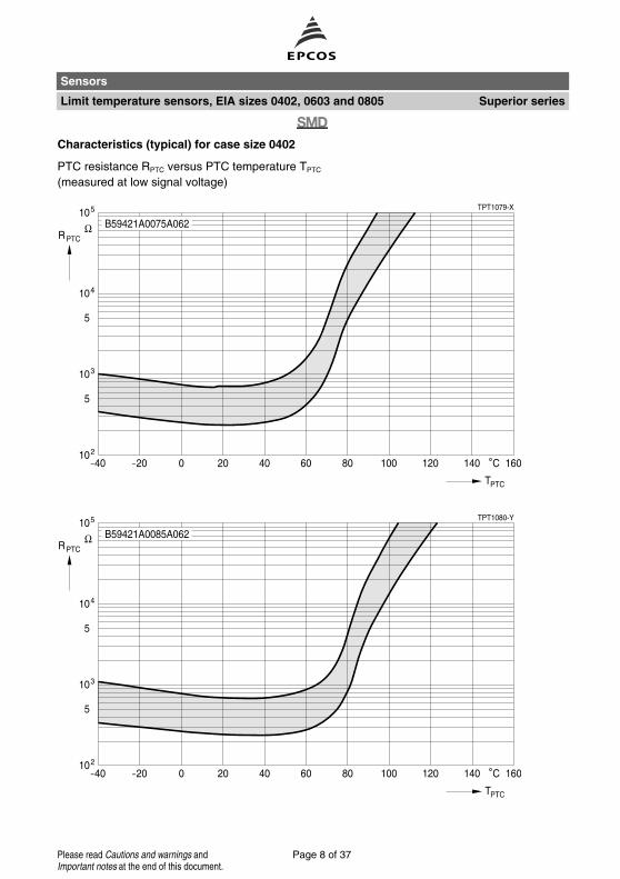
Characteristics (typical) for case size 0402
PTC resistance RPTC versus PTC temperature TPTC
(measured at low signal voltage)
Sensors
Limit temperature sensors, EIA sizes 0402, 0603 and 0805 Superior series
Page 8 of 37Please read Cautions and warnings andImportant notes at the end of this document.

Characteristics (typical) for case size 0402
PTC resistance RPTC versus PTC temperature TPTC
(measured at low signal voltage)
Sensors
Limit temperature sensors, EIA sizes 0402, 0603 and 0805 Superior series
Page 9 of 37Please read Cautions and warnings andImportant notes at the end of this document.
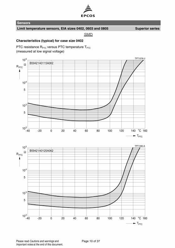
Characteristics (typical) for case size 0402
PTC resistance RPTC versus PTC temperature TPTC
(measured at low signal voltage)
Sensors
Limit temperature sensors, EIA sizes 0402, 0603 and 0805 Superior series
Page 10 of 37Please read Cautions and warnings andImportant notes at the end of this document.

Characteristics (typical) for case size 0402
PTC resistance RPTC versus PTC temperature TPTC
(measured at low signal voltage)
Sensors
Limit temperature sensors, EIA sizes 0402, 0603 and 0805 Superior series
Page 11 of 37Please read Cautions and warnings andImportant notes at the end of this document.

Characteristics (typical) for case size 0603
PTC resistance RPTC versus PTC temperature TPTC
(measured at low signal voltage)
Sensors
Limit temperature sensors, EIA sizes 0402, 0603 and 0805 Superior series
Page 12 of 37Please read Cautions and warnings andImportant notes at the end of this document.
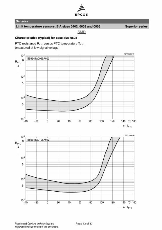
Characteristics (typical) for case size 0603
PTC resistance RPTC versus PTC temperature TPTC
(measured at low signal voltage)
Sensors
Limit temperature sensors, EIA sizes 0402, 0603 and 0805 Superior series
Page 13 of 37Please read Cautions and warnings andImportant notes at the end of this document.

Characteristics (typical) for case size 0603
PTC resistance RPTC versus PTC temperature TPTC
(measured at low signal voltage)
Sensors
Limit temperature sensors, EIA sizes 0402, 0603 and 0805 Superior series
Page 14 of 37Please read Cautions and warnings andImportant notes at the end of this document.

Characteristics (typical) for case size 0603
PTC resistance RPTC versus PTC temperature TPTC
(measured at low signal voltage)
Sensors
Limit temperature sensors, EIA sizes 0402, 0603 and 0805 Superior series
Page 15 of 37Please read Cautions and warnings andImportant notes at the end of this document.

Characteristics (typical) for case size 0805
PTC resistance RPTC versus PTC temperature TPTC
(measured at low signal voltage)
Sensors
Limit temperature sensors, EIA sizes 0402, 0603 and 0805 Superior series
Page 16 of 37Please read Cautions and warnings andImportant notes at the end of this document.

Characteristics (typical) for case size 0805
PTC resistance RPTC versus PTC temperature TPTC
(measured at low signal voltage)
Sensors
Limit temperature sensors, EIA sizes 0402, 0603 and 0805 Superior series
Page 17 of 37Please read Cautions and warnings andImportant notes at the end of this document.

Characteristics (typical) for case size 0805
PTC resistance RPTC versus PTC temperature TPTC
(measured at low signal voltage)
Sensors
Limit temperature sensors, EIA sizes 0402, 0603 and 0805 Superior series
Page 18 of 37Please read Cautions and warnings andImportant notes at the end of this document.

Characteristics (typical) for case size 0805
PTC resistance RPTC versus PTC temperature TPTC
(measured at low signal voltage)
Sensors
Limit temperature sensors, EIA sizes 0402, 0603 and 0805 Superior series
Page 19 of 37Please read Cautions and warnings andImportant notes at the end of this document.

1) ≤ 0.2 mm over 10 sprocket holes
Taping and packing
Many of the components presented in this data book are suitable for processing on automatic in-
sertion or placement machines. These thermistors can be supplied on tape for easy handling by
automatic systems. The individual modes of taping and packing will be described in the following.
1 Taping of SMD thermistors
1.1 Blister tape (to IEC 60286-3)
Figure 1
Dimension
(mm)
8-mm tape 16-mm tape Tolerance
(mm)
24-mm tape Tolerance
(mm)
D0
D1
1.50
1.00
1.50
1.50
+ 0.10/ 0
min.
1.50
1.50
+ 0.10
+ 0.10
P0
P2
P1
4.00
2.00
4.00
4.00
2.00
12.00
± 0.10 1)
± 0.05
± 0.10
4.00
2.00
16.00
± 0.10
± 0.10
± 0.10
W 8.00 16.00 ± 0.30 24.00 + 0.30/ 0.1
E 1.75 1.75 ± 0.10 1.75 ± 0.10
F 3.50 7.50 ± 0.05 11.50 ± 0.10
G 0.75 0.75 min. 0.75 min.
A0 x B0, K0, T2: The rated dimensions of the component compartment have been derived from the
relevant component specification and are chosen such that the components cannot change their
orientation within the tape.
Sensors
Limit temperature sensors, EIA sizes 0402, 0603 and 0805 Superior series
Page 20 of 37Please read Cautions and warnings andImportant notes at the end of this document.

Part orientation in tape pocket for blister tape
For chip thermistors case sizes 0805 and 1210
Figure 2
Additional taping information
For chip thermistors case sizes 0805 and 1210
Reel material Polystyrol (PS)
Tape material Polystyrol (PS) or Polycarbonat (PC) or PVC
Tape break force min. 10 N
Top cover tape strength min. 10 N
Top cover tape peel force 0.2 ... 0.6 N for 8-mm tape and 0.2 ... 0.8 N for 12-mm tape at
a peel speed of 300 mm/min
Tape peel angle Angle between top cover tape and the direction of feed during
peel off: 165° ... 180°Cavity play Each part rests in the cavity so that the angle between the part
and cavity center line is no more than 20°
Sensors
Limit temperature sensors, EIA sizes 0402, 0603 and 0805 Superior series
Page 21 of 37Please read Cautions and warnings andImportant notes at the end of this document.
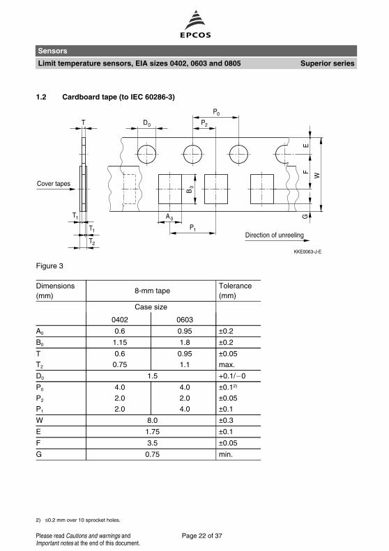
2) ≤0.2 mm over 10 sprocket holes.
1.2 Cardboard tape (to IEC 60286-3)
Figure 3
Dimensions
(mm)8-mm tape
Tolerance
(mm)
Case size
0402 0603
A0 0.6 0.95 ±0.2
B0 1.15 1.8 ±0.2
T 0.6 0.95 ±0.05
T2 0.75 1.1 max.
D0 1.5 +0.1/ 0
P0 4.0 4.0 ±0.12)
P2 2.0 2.0 ±0.05
P1 2.0 4.0 ±0.1
W 8.0 ±0.3
E 1.75 ±0.1
F 3.5 ±0.05
G 0.75 min.
Sensors
Limit temperature sensors, EIA sizes 0402, 0603 and 0805 Superior series
Page 22 of 37Please read Cautions and warnings andImportant notes at the end of this document.

Part orientation in tape pocket for cardboard tape
For chip thermistors case sizes 0402 and 0603
Figure 4
Additional taping information
Reel material Polystyrol (PS)
Tape material Cardboard
Tape break force min. 10 N
Top cover tape strength min. 10 N
Top cover tape peel force 0.1 ... 0.65 N at a peel speed of 300 mm/min
Tape peel angle Angle between top cover tape and the direction of feed during
peel off: 165° ... 180°Cavity play Each part rests in the cavity so that the angle between the part
and cavity center line is no more than 20°
Sensors
Limit temperature sensors, EIA sizes 0402, 0603 and 0805 Superior series
Page 23 of 37Please read Cautions and warnings andImportant notes at the end of this document.
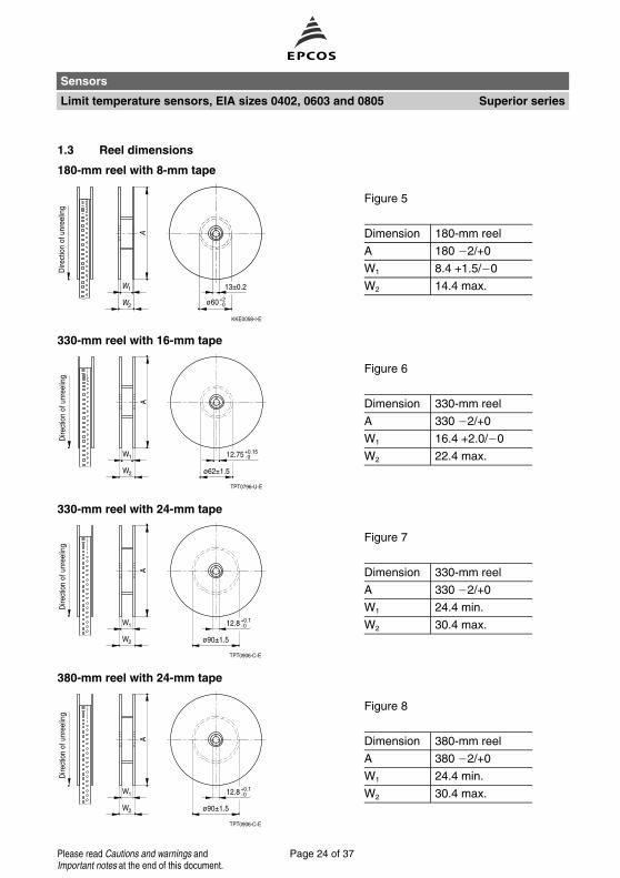
1.3 Reel dimensions
180-mm reel with 8-mm tape
Figure 5
Dimension 180-mm reel
A 180 2/+0
W1 8.4 +1.5/ 0
W2 14.4 max.
330-mm reel with 16-mm tape
Figure 6
Dimension 330-mm reel
A 330 2/+0
W1 16.4 +2.0/ 0
W2 22.4 max.
330-mm reel with 24-mm tape
Figure 7
Dimension 330-mm reel
A 330 2/+0
W1 24.4 min.
W2 30.4 max.
380-mm reel with 24-mm tape
Figure 8
Dimension 380-mm reel
A 380 2/+0
W1 24.4 min.
W2 30.4 max.
Sensors
Limit temperature sensors, EIA sizes 0402, 0603 and 0805 Superior series
Page 24 of 37Please read Cautions and warnings andImportant notes at the end of this document.
Mounting instructions
1 Soldering
1.1 Leaded PTC thermistors
Leaded PTC thermistors follow the solderability requirements of IEC 60068-2-20.
During soldering, care must be taken that the thermistors are not damaged by excessive heat.
The following maximum temperatures, maximum time spans and minimum distances have to be
observed:
Solder containing lead
(SnPb 60/40)
Lead-free solder
(Sn96.5Ag3Cu0.5)
Solderability Solder bath temperature 230 °CSoldering time 3 s
Solder bath temperature 245 °CSoldering time 3 s
Resistance to
soldering heat
Soldering iron temperature 350 °CSoldering time 3 s
Solder bath temperature 260 °CSoldering time 10 s
Distance to thermistor has to be ≥6 mm. Under more severe soldering conditions the resistance
may change. Soldering conditions for wave soldering are given in chapter 1.4.1.
1.2 Leadless PTC thermistors
In case of PTC thermistors without leads, soldering is restricted to devices which are provided
with a solderable metallization. The temperature shock caused by the application of hot solder
may produce fine cracks in the ceramic, resulting in changes in resistance.
In addition, soldering methods should be employed which permit short soldering times.
Soldering conditions for wave soldering are given in chapter 1.4.1.
1.3 SMD PTC thermistors
The notes on soldering leadless thermistors also apply to the SMD versions (refer to
IEC 60068-2-58). Soldering conditions for wave soldering are given in chapter 1.4.1., for reflow
soldering in chapter 1.4.2.
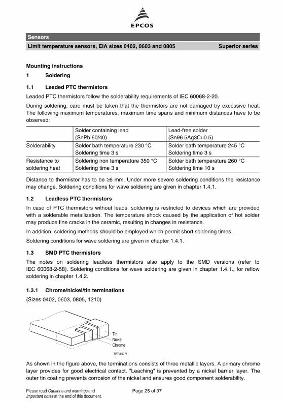
1.3.1 Chrome/nickel/tin terminations
(Sizes 0402, 0603, 0805, 1210)
As shown in the figure above, the terminations consists of three metallic layers. A primary chrome
layer provides for good electrical contact. "Leaching" is prevented by a nickel barrier layer. The
outer tin coating prevents corrosion of the nickel and ensures good component solderability.
Sensors
Limit temperature sensors, EIA sizes 0402, 0603 and 0805 Superior series
Page 25 of 37Please read Cautions and warnings andImportant notes at the end of this document.

1.3.2 Test methods for wetting and resistance to soldering heat
a) Solder bath method according to IEC 60068-2-58
Applicable for SMD components with wire or tag terminations. In case the SMD-component does
not have a completely closed housing, only the wires or tags may be immersed into the solder
bath.
Lead-free solder
(Sn96.5Ag3Cu0.5)
Solder containing lead
(SnPb 60/40)
Wetting test Bath temperature 250 °CSoldering time 3 s
Bath temperature 215 °CSoldering time 3 s
Resistance to
soldering heat
Bath temperature 260 °CSoldering time 10 s
Bath temperature 260 °CSoldering time 10 s
b) Solder reflow method according to IEC 60068-2-58
Applicable for chip-style SMD components. Reflow temperature profile is stated in
IEC 60068-2-58, 8.1.2.1 for wetting test and 8.1.2.2 for resistance to soldering heat test.
Lead-free solder
(Sn96.5Ag3Cu0.5)
Solder containing lead
(SnPb 60/40)
Wetting test Peak temperature 225 ... 235 °CDuration maximum 20 s
Peak temperature 215 °CDuration maximum 10 s
Resistance to
soldering heat
Peak temperature 245 ... 255 °CDuration maximum 20 s
Peak temperature 235 °CDuration maximum 30 s
Sensors
Limit temperature sensors, EIA sizes 0402, 0603 and 0805 Superior series
Page 26 of 37Please read Cautions and warnings andImportant notes at the end of this document.
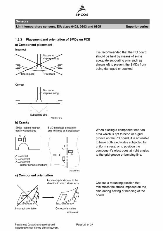
1.3.3 Placement and orientation of SMDs on PCB
a) Component placement
It is recommended that the PC board
should be held by means of some
adequate supporting pins such as
shown left to prevent the SMDs from
being damaged or cracked.
b) Cracks
When placing a component near an
area which is apt to bend or a grid
groove on the PC board, it is advisable
to have both electrodes subjected to
uniform stress, or to position the
component's electrodes at right angles
to the grid groove or bending line.
c) Component orientation
Choose a mounting position that
minimizes the stress imposed on the
chip during flexing or bending of the
board.
Sensors
Limit temperature sensors, EIA sizes 0402, 0603 and 0805 Superior series
Page 27 of 37Please read Cautions and warnings andImportant notes at the end of this document.

1.4 Soldering profiles
1.4.1 Wave soldering
Recommended temperature profile for wave soldering following IEC 61760-1. Applicable for lead-
ed PTCs and selected SMD PTCs (case sizes 3225 and 4032 as well as superior series for case
sizes 0402, 0603 and 0805 limit temperature sensors).
Sensors
Limit temperature sensors, EIA sizes 0402, 0603 and 0805 Superior series
Page 28 of 37Please read Cautions and warnings andImportant notes at the end of this document.
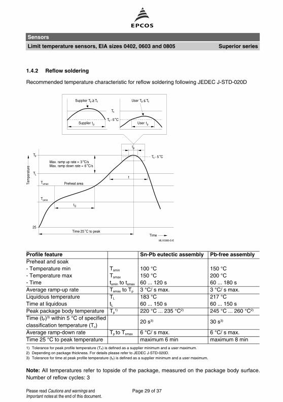
1.4.2 Reflow soldering
Recommended temperature characteristic for reflow soldering following JEDEC J-STD-020D
Profile feature Sn-Pb eutectic assembly Pb-free assembly
Preheat and soak
- Temperature min Tsmin 100 °C 150 °C- Temperature max Tsmax 150 °C 200 °C- Time tsmin to tsmax 60 ... 120 s 60 ... 180 s
Average ramp-up rate Tsmax to Tp 3 °C/ s max. 3 °C/ s max.
Liquidous temperature TL 183 °C 217 °CTime at liquidous tL 60 ... 150 s 60 ... 150 s
Peak package body temperature Tp1) 220 °C ... 235 °C2) 245 °C ... 260 °C2)
Time (tP)3) within 5 °C of specified
classification temperature (Tc)20 s3) 30 s3)
Average ramp-down rate Tp to Tsmax 6 °C/ s max. 6 °C/ s max.
Time 25 °C to peak temperature maximum 6 min maximum 8 min
1) Tolerance for peak profile temperature (TP) is defined as a supplier minimum and a user maximum.
2) Depending on package thickness. For details please refer to JEDEC J-STD-020D.
3) Tolerance for time at peak profile temperature (tP) is defined as a supplier minimum and a user maximum.
Note: All temperatures refer to topside of the package, measured on the package body surface.
Number of reflow cycles: 3
Sensors
Limit temperature sensors, EIA sizes 0402, 0603 and 0805 Superior series
Page 29 of 37Please read Cautions and warnings andImportant notes at the end of this document.
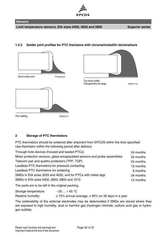
1.4.3 Solder joint profiles for PTC theristors with chrome/nickel/tin terminations
2 Storage of PTC thermistors
PTC thermistors should be soldered after shipment from EPCOS within the time specified:
Use thermistor within the following period after delivery:
Through-hole devices (housed and leaded PTCs) 24 months
Motor protection sensors, glass-encapsulated sensors and probe assemblies 24 months
Telecom pair and quattro protectors (TPP, TQP) 24 months
Leadless PTC thermistors for pressure contacting 12 months
Leadless PTC thermistors for soldering 6 months
SMDs in EIA sizes 3225 and 4032, and for PTCs with metal tags 24 months
SMDs in EIA sizes 0402, 0603, 0805 and 1210 12 months
The parts are to be left in the original packing.
Storage temperature: 25 ... + 45 °CRelative humidity: ≤ 75% annual average, ≤ 95% on 30 days in a year
The solderability of the external electrodes may be deteriorated if SMDs are stored where they
are exposed to high humidity, dust or harmful gas (hydrogen chloride, sulfuric acid gas or hydro-
gen sulfide).
Sensors
Limit temperature sensors, EIA sizes 0402, 0603 and 0805 Superior series
Page 30 of 37Please read Cautions and warnings andImportant notes at the end of this document.
Do not store SMDs where they are exposed to heat or direct sunlight. Otherwise, the packing ma-
terial may be deformed or SMDs may stick together, causing problems during mounting.
After opening the factory seals, such as polyvinyl-sealed packages, it is recommended to use the
components as soon as possible.
3 Conductive adhesion
An alternative to soldering is the gluing of thermistors with conductive adhesives. The benfit of
this method is that it involves no thermal stress. The adhesives used must be chemically inert and
suitable for the temperatures arising at the surface of the termistor.
4 Clamp contacting
Pressure contacting by springs is required for applications involving frequent switching and high
turn-on powers. Soldering is not allowed for such applications in order to avoid operational failure
in the long term. PTC thermistors for heating and motor starting have metallized surfaces for
clamp contacting.
5 Robustness of terminations
The leads meet the requirements of IEC 60068-2-21. They may not be bent closer than 4 mm
from the solder joint on the thermistor body or from the point at which they leave the
feedthroughs. During bending, any mechanical stress at the outlet of the leads must be removed.
The bending radius should be at least 0.75 mm.
Tensile strength: Test Ua1:
Leads
∅ ≤ 0.5 mm = 5 N
∅ > 0.5 mm = 10 N
Bending strength: Test Ub:
Two 90°-bends in opposite directions at a weight of 0.25 kg.
Torsional strength: Test Uc: severity 2
The lead is bent by 90° at a distance of 6 to 6.5 mm from the thermistor body.
The bending radius of the leads should be approx. 0.75 mm. Two torsions of
180° each (severity 2).
Sensors
Limit temperature sensors, EIA sizes 0402, 0603 and 0805 Superior series
Page 31 of 37Please read Cautions and warnings andImportant notes at the end of this document.

When subjecting leads to mechanical stress, the following should be observed:
Tensile stress on leads
During mounting and operation tensile forces on the leads are to be avoided.
Bending of leads
Bending of the leads directly on the thermistor body is not permissible.
A lead may be bent at a minimum distance of twice the wire's diameter +2 mm from the solder
joint on the thermistor body. During bending the wire must be mechanically relieved at its outlet.
The bending radius should be at least 0.75 mm.
Twisting of leads
The twisting (torsion) by 180° of a lead bent by 90° is permissible at 6 mm from the bottom of the
thermistor body.
6 Sealing and potting
When thermistors are sealed or potted, there must be no mechanical stress through differing ther-
mal expansion in the curing process and during later operation. In the curing process the upper
category temperature of the thermistor must not be exceeded. It is also necessary to ensure that
the potting compound is chemically inert.
Sealing and potting compounds may degenerate the titanate ceramic of PTC thermistors and lead
to the formation of low-ohmic conduction bridges. In conjunction with a change in dissipation con-
ditions due to the potting compound, local overheating may finally damage the thermistor.
Therefore sealing and potting should be avoided whenever possible.
7 Cleaning
You may use common cleaners based on organic solvents (eg dowanol or alcohol) to clean ce-
ramic and solder joints.
For sufficient cleaning flux must be completely removed.
Solvents may cause plastic encapsulations to swell or detach. So be sure to check the suitability
of a solvent before using it.
Caution is required with ultrasonic processes. If the sound power is too high, for example, it can
degrade the adhesive strength of the terminal metallization or couse the encapsulation to detach.
After cleaning drying is promptly necessary.
Sensors
Limit temperature sensors, EIA sizes 0402, 0603 and 0805 Superior series
Page 32 of 37Please read Cautions and warnings andImportant notes at the end of this document.
Cautions and warnings
General
EPCOS thermistors are designed for specific applications and should not be used for purposes
not identified in our specifications, application notes and data books unless otherwise agreed
with EPCOS during the design-in-phase.
Ensure suitability of thermistor through reliability testing during the design-in phase. The ther-
mistors should be evaluated taking into consideration worst-case conditions.
Storage
Store thermistors only in original packaging. Do not open the package before storage.
Storage conditions in original packaging: storage temperature 25 °C ... +45 °C, relative hu-
midity ≤75% annual mean, maximum 95%, dew precipitation is inadmissible.
Avoid contamination of thermistors surface during storage, handling and processing.
Avoid storage of thermistor in harmful environment with effect on function on long-term opera-
tion (examples given under operation precautions).
Use thermistor within the following period after delivery:
Through-hole devices (housed and leaded PTCs): 24 months
Motor protection sensors, glass-encapsulated sensors and probe assemblies: 24 months
Telecom pair and quattro protectors (TPP, TQP): 24 months
Leadless PTC thermistors for pressure contacting: 12 months
Leadless PTC thermistors for soldering: 6 months
SMDs in EIA sizes 3225 and 4032, and for PTCs with metal tags: 24 months
SMDs in EIA sizes 0402, 0603, 0805 and 1210: 12 months
Handling
PTCs must not be dropped. Chip-offs must not be caused during handling of PTCs.
Components must not be touched with bare hands. Gloves are recommended.
Avoid contamination of thermistor surface during handling.
Soldering (where applicable)
Use rosin-type flux or non-activated flux.
Insufficient preheating may cause ceramic cracks.
Rapid cooling by dipping in solvent is not recommended.
Complete removal of flux is recommended.
Standard PTC heaters are not suitable for soldering.
Sensors
Limit temperature sensors, EIA sizes 0402, 0603 and 0805 Superior series
Page 33 of 37Please read Cautions and warnings andImportant notes at the end of this document.

Mounting
Electrode must not be scratched before/during/after the mounting process.
Contacts and housing used for assembly with thermistor have to be clean before mounting. Es-
pecially grease or oil must be removed.
When PTC thermistors are encapsulated with sealing material, the precautions given in chapter
"Mounting instructions", "Sealing and potting" must be observed.
When the thermistor is mounted, there must not be any foreign body between the electrode of
the thermistor and the clamping contact.
The minimum force of the clamping contacts pressing against the PTC must be 10 N.
During operation, the thermistor’s surface temperature can be very high. Ensure that adjacent
components are placed at a sufficient distance from the thermistor to allow for proper cooling at
the thermistors.
Ensure that adjacent materials are designed for operation at temperatures comparable to the
surface temperature of thermistor. Be sure that surrounding parts and materials can withstand
this temperature.
Avoid contamination of thermistor surface during processing.
Operation
Use thermistors only within the specified temperature operating range.
Use thermistors only within the specified voltage and current ranges.
Environmental conditions must not harm the thermistors. Use thermistors only in normal at-
mospheric conditions. Avoid use in deoxidizing gases (chlorine gas, hydrogen sulfide gas, am-
monia gas, sulfuric acid gas etc), corrosive agents, humid or salty conditions. Contact with any
liquids and solvents should be prevented.
Be sure to provide an appropriate fail-safe function to prevent secondary product damage
caused by abnormal function (e.g. use VDR for limitation of overvoltage condition).
Sensors
Limit temperature sensors, EIA sizes 0402, 0603 and 0805 Superior series
Page 34 of 37Please read Cautions and warnings andImportant notes at the end of this document.

Symbols and terms
A Area
Cth Heat capacity
f Frequency
I Current
Iin,coil Inrush current through degaussing coil
Imax Maximum current
IR Rated current
IPTC PTC current
Ir Residual currrent
Ir,coil Residual currrent through degaussing coil
Ir,oil Residual currrent in oil (for level sensors)
Ir,air Residual currrent in air (for level sensors)
IRMS Root-mean-square value of current
IS Switching current
ISmax Maximum switching current
LCT Lower category temperature
N Number (integer)
P Power
P25 Maximum power at 25 °CPel Electrical power
Pdiss Dissipation power
Rmin Minimum resistance
RR Rated resistance
∆RR Tolerance of RR
RP Parallel resistance
RPTC PTC resistance
Rref Reference resistance
RS Series resistance
R25 Resistance at 25 °CR25,match Resistance matching per reel/ packing unit at 25 °C∆R25 Tolerance of R25
T Temperature
t Time
TA Ambient temperature
ta Thermal threshold time
TC Ferroelectric Curie temperature
Sensors
Limit temperature sensors, EIA sizes 0402, 0603 and 0805 Superior series
Page 35 of 37Please read Cautions and warnings andImportant notes at the end of this document.

tE Settling time (for level sensors)
TUCT Upper category temperature
TLCT Lower category temperature
TR Rated temperature
Tsense Sensing temperature
Top Operating temperature
TPTC PTC temperature
tR Response time
Tref Reference temperature
TRmin Temperature at minimum resistance
tS Switching time
Tsurf Surface temperature
UCT Upper category temperature
V or Vel Voltage (with subscript only for distinction from volume)
VRMS Root-mean-square value of voltage
VBD Breakdown voltage
Vins Insulation test voltage
Vmax Maximum operating voltage
Vmax,dyn Maximum dynamic (short-time) operating voltage
Vmeas Measuring voltage
Vmeas,max Maximum measuring voltage
VR Rated voltage
VPTC Voltage drop across a PTC thermistor
α Temperature coefficient
∆ Tolerance, change
δth Dissipation factor
τth Thermal cooling time constant
λ Failure rate
Lead spacing (in mm)
Abbreviations / Notes
Surface-mount devices
* To be replaced by a number in ordering codes, type designations etc.
+ To be replaced by a letter
All dimensions are given in mm.
The commas used in numerical values denote decimal points.
Sensors
Limit temperature sensors, EIA sizes 0402, 0603 and 0805 Superior series
Page 36 of 37Please read Cautions and warnings andImportant notes at the end of this document.
The following applies to all products named in this publication:
1. Some parts of this publication contain statements about the suitability of our products for
certain areas of application. These statements are based on our knowledge of typical re-
quirements that are often placed on our products in the areas of application concerned. We
nevertheless expressly point out that such statements cannot be regarded as binding
statements about the suitability of our products for a particular customer application.
As a rule, EPCOS is either unfamiliar with individual customer applications or less familiar
with them than the customers themselves. For these reasons, it is always ultimately incum-
bent on the customer to check and decide whether an EPCOS product with the properties de-
scribed in the product specification is suitable for use in a particular customer application.
2. We also point out that in individual cases, a malfunction of electronic components or
failure before the end of their usual service life cannot be completely ruled out in the
current state of the art, even if they are operated as specified. In customer applications
requiring a very high level of operational safety and especially in customer applications in
which the malfunction or failure of an electronic component could endanger human life or
health (e.g. in accident prevention or lifesaving systems), it must therefore be ensured by
means of suitable design of the customer application or other action taken by the customer
(e.g. installation of protective circuitry or redundancy) that no injury or damage is sustained by
third parties in the event of malfunction or failure of an electronic component.
3. The warnings, cautions and product-specific notes must be observed.
4. In order to satisfy certain technical requirements, some of the products described in this
publication may contain substances subject to restrictions in certain jurisdictions (e.g.
because they are classed as hazardous). Useful information on this will be found in our Ma-
terial Data Sheets on the Internet (www.epcos.com/material). Should you have any more de-
tailed questions, please contact our sales offices.
5. We constantly strive to improve our products. Consequently, the products described in this
publication may change from time to time. The same is true of the corresponding product
specifications. Please check therefore to what extent product descriptions and specifications
contained in this publication are still applicable before or when you place an order. We also
reserve the right to discontinue production and delivery of products. Consequently, we
cannot guarantee that all products named in this publication will always be available. The
aforementioned does not apply in the case of individual agreements deviating from the fore-
going for customer-specific products.
6. Unless otherwise agreed in individual contracts, all orders are subject to the current ver-
sion of the "General Terms of Delivery for Products and Services in the Electrical In-
dustry" published by the German Electrical and Electronics Industry Association
(ZVEI).
7. The trade names EPCOS, BAOKE, Alu-X, CeraDiode, CSMP, CSSP, CTVS, DeltaCap,
DigiSiMic, DSSP, FormFit, MiniBlue, MiniCell, MKK, MKD, MLSC, MotorCap, PCC,
PhaseCap, PhaseCube, PhaseMod, PhiCap, SIFERRIT, SIFI, SIKOREL, SilverCap,
SIMDAD, SiMic, SIMID, SineFormer, SIOV, SIP5D, SIP5K, ThermoFuse, WindCap are trade-
marks registered or pending in Europe and in other countries. Further information will be
found on the Internet at www.epcos.com/trademarks.
Important notes
Page 37 of 37